generator protection reg650 commissioning manual · basic ied functions ... visual inspection ... o...
TRANSCRIPT

Relion® 650 series
Generator protection REG650Commissioning manual


Document ID: 1MRK 502 049-UENIssued: October 2016
Revision: AProduct version: 1.3
© Copyright 2013 ABB. All rights reserved

Copyright
This document and parts thereof must not be reproduced or copied without writtenpermission from ABB, and the contents thereof must not be imparted to a third party,nor used for any unauthorized purpose.
The software and hardware described in this document is furnished under a license andmay be used or disclosed only in accordance with the terms of such license.
This product includes software developed by the OpenSSL Project for use in theOpenSSL Toolkit. (http://www.openssl.org/)
This product includes cryptographic software written/developed by: Eric Young([email protected]) and Tim Hudson ([email protected]).
TrademarksABB and Relion are registered trademarks of the ABB Group. All other brand orproduct names mentioned in this document may be trademarks or registeredtrademarks of their respective holders.
WarrantyPlease inquire about the terms of warranty from your nearest ABB representative.
ABB AB
Grid Automation Products
SE-721 59 Västerås
Sweden
Telephone: +46 (0) 21 32 50 00
Facsimile: +46 (0) 21 14 69 18
http://www.abb.com/protection-control

Conformity
This product complies with the directive of the Council of the European Communitieson the approximation of the laws of the Member States relating to electromagneticcompatibility (EMC Directive 2004/108/EC) and concerning electrical equipment foruse within specified voltage limits (Low-voltage directive 2006/95/EC). Thisconformity is the result of tests conducted by ABB in accordance with the productstandards EN 50263 and EN 60255-26 for the EMC directive, and with the productstandards EN 60255-1 and EN 60255-27 for the low voltage directive. The product isdesigned in accordance with the international standards of the IEC 60255 series.

Disclaimer
The data, examples and diagrams in this manual are included solely for the concept orproduct description and are not to be deemed as a statement of guaranteed properties.All persons responsible for applying the equipment addressed in this manual mustsatisfy themselves that each intended application is suitable and acceptable, includingthat any applicable safety or other operational requirements are complied with. Inparticular, any risks in applications where a system failure and/or product failurewould create a risk for harm to property or persons (including but not limited topersonal injuries or death) shall be the sole responsibility of the person or entityapplying the equipment, and those so responsible are hereby requested to ensure thatall measures are taken to exclude or mitigate such risks.
This document has been carefully checked by ABB but deviations cannot becompletely ruled out. In case any errors are detected, the reader is kindly requested tonotify the manufacturer. Other than under explicit contractual commitments, in noevent shall ABB be responsible or liable for any loss or damage resulting from the useof this manual or the application of the equipment.

Safety information
Dangerous voltages can occur on the connectors, even though theauxiliary voltage has been disconnected.
Non-observance can result in death, personal injury or substantialproperty damage.
Only a competent electrician is allowed to carry out the electricalinstallation.
National and local electrical safety regulations must always befollowed.
The frame of the IED has to be carefully earthed.
Whenever changes are made in the IED, measures should be taken toavoid inadvertent tripping.
The IED contains components which are sensitive to electrostaticdischarge. ESD precautions shall always be observed prior totouching components.


Table of contents
Section 1 Introduction.......................................................................7This manual........................................................................................ 7Intended audience.............................................................................. 7Product documentation.......................................................................8
Product documentation set............................................................8Document revision history............................................................. 9Related documents........................................................................9
Symbols and conventions.................................................................10Symbols.......................................................................................10Document conventions................................................................11
Section 2 Available functions......................................................... 13Main protection functions..................................................................13Back-up protection functions............................................................ 14Control and monitoring functions......................................................15Station communication..................................................................... 18Basic IED functions.......................................................................... 19
Section 3 Starting up......................................................................21Factory and site acceptance testing................................................. 21Commissioning checklist.................................................................. 21Checking the power supply.............................................................. 22Energizing the IED............................................................................22
Checking the IED operation.........................................................22IED start-up sequence.................................................................22
Setting up communication between PCM600 and the IED...............23Writing an application configuration to the IED.................................28Checking CT circuits.........................................................................29Checking VT circuits.........................................................................29Using the RTXP test switch.............................................................. 30Checking binary input and output circuits.........................................31
Binary input circuits..................................................................... 31Binary output circuits................................................................... 31
Checking optical connections........................................................... 31
Section 4 Establishing connection and verifying the IEC 61850station communication....................................................33Setting the station communication....................................................33Verifying the station communication.................................................33
Table of contents
1Commissioning manual
Section 5 Testing IED operation.....................................................35Preparing the IED to verify settings.................................................. 35Activating the test mode................................................................... 37Preparing the connection to the test equipment............................... 37Connecting the test equipment to the IED........................................38Releasing the function to be tested.................................................. 39Verifying analog primary and secondary measurement................... 39Testing the protection functionality................................................... 41
Section 6 Testing functionality........................................................43Testing disturbance report................................................................43
Introduction..................................................................................43Disturbance report settings..........................................................43
Identifying the function to test in the technical reference manual ....43Testing differential protection functions............................................ 44
Transformer differential protection T3WPDIF .............................44Verifying the settings.............................................................. 44Completing the test................................................................ 45
Restricted earth-fault protection, low impedance REFPDIF ....... 45Verifying the settings.............................................................. 45Completing the test................................................................ 46
High impedance differential protection HZPDIF ......................... 46Verifying the settings.............................................................. 46Completing the test................................................................ 47
Generator differential protection GENPDIF ................................47Verifying the settings.............................................................. 47Completing the test................................................................ 48
Testing impedance protection functions........................................... 48Power swing detection ZMRPSB ................................................48
Verifying the settings.............................................................. 50Testing the power swing detection function ZMRPSB .......... 50Testing the tR1 timer.............................................................. 50Testing the block input, interaction between FDPSPDISand ZMRPSB ........................................................................ 51Completing the test................................................................ 51
Underimpedance protection for generators and transformersZGCPDIS ....................................................................................51
Distance protection zones ZGCPDIS..................................... 52Phase-to-phase faults............................................................ 52
Loss of excitation LEXPDIS ........................................................53Verifying the settings.............................................................. 53Completing the test................................................................ 54
Out-of-step OOSPPAM............................................................... 55
Table of contents
2Commissioning manual

Verifying the settings.............................................................. 55Load encroachment LEPDIS ......................................................58
Measuring the operate limit of set values...............................59Completing the test................................................................ 59
Testing current protection functions................................................. 59Four step phase overcurrent protection 3-phase outputOC4PTOC................................................................................... 59
Verifying the settings.............................................................. 59Completing the test................................................................ 60
Four step residual overcurrent protection, zero or negativesequence direction EF4PTOC ....................................................61
Four step directional residual overcurrent protection ............ 61Four step non-directional residual overcurrent protection...... 62Completing the test................................................................ 62
Sensitive directional residual overcurrent and powerprotection SDEPSDE ..................................................................62
Measuring the operate and time limit for set values...............62Completing the test................................................................ 67
Thermal overload protection, two time constants TRPTTR ........67Checking operate and reset values........................................67Completing the test................................................................ 68
Breaker failure protection, phase segregated activation andoutput CCRBRF...........................................................................68
Checking the phase current operate value, IP>..................... 69Checking the residual (earth fault) current operate valueIN> set below IP>................................................................... 69Checking the re-trip and back-up times..................................69Verifying the re-trip mode....................................................... 70Verifying the back-up trip mode..............................................70Verifying the case RetripMode = Contact...............................71Verifying the function mode Current&Contact........................ 72Completing the test................................................................ 73
Pole discordance protection CCRPLD........................................ 73Verifying the settings.............................................................. 73Completing the test................................................................ 73
Directional underpower protection GUPPDUP ...........................74Verifying the settings.............................................................. 74Completing the test................................................................ 75
Directional overpower protection GOPPDOP .............................75Verifying the settings.............................................................. 76Completing the test................................................................ 76
Accidental energizing protection for synchronous generatorAEGGAPC...................................................................................77
Verifying the settings.............................................................. 77
Table of contents
3Commissioning manual
Negative-sequence time overcurrent protection for machinesNS2PTOC ...................................................................................77
Verifying settings by secondary injection............................... 77Voltage-restrained time overcurrent protection VRPVOC........... 79
Verifying the settings.............................................................. 79Completing the test................................................................ 80
Testing voltage protection functions................................................. 80Two step undervoltage protection UV2PTUV .............................80
Verifying the setting................................................................81Completing the test................................................................ 82
Two step overvoltage protection OV2PTOV ...............................82Verification of single-phase voltage and time delay tooperate for Step 1...................................................................82Completing the test................................................................ 83
Two step residual overvoltage protection ROV2PTOV .............. 84Verifying the settings.............................................................. 84Completing the test................................................................ 85
Overexcitation protection OEXPVPH ......................................... 85Verifying the settings.............................................................. 85Completing the test................................................................ 85
100% Stator earth fault protection, 3rd harmonic basedSTEFPHIZ .................................................................................. 86
Testing....................................................................................86Verifying settings.................................................................... 87Completing the test................................................................ 88
Testing frequency protection functions.............................................89Underfrequency protection SAPTUF ..........................................89
Verifying the settings.............................................................. 89Completing the test................................................................ 90
Overfrequency protection SAPTOF ............................................91Verifying the settings.............................................................. 91Completing the test................................................................ 92
Rate-of-change frequency protection SAPFRC ..........................93Verifying the settings.............................................................. 93Completing the test................................................................ 93
Testing secondary system supervision functions............................. 94Fuse failure supervision SDDRFUF............................................ 94
Checking that the binary inputs and outputs operate asexpected ................................................................................94Measuring the operate value for the negative sequencefunction ..................................................................................95Measuring the operate value for the zero-sequencefunction ..................................................................................96Checking the operation of the du/dt and di/dt based function 96
Table of contents
4Commissioning manual

Completing the test................................................................ 97Testing control functions...................................................................98
Synchrocheck, energizing check, and synchronizingSESRSYN................................................................................... 98
Testing the synchronizing function....................................... 100Testing the synchrocheck check.......................................... 101Testing the energizing check................................................104Testing the voltage selection................................................106Completing the test.............................................................. 106
Interlocking................................................................................ 106Apparatus control APC..............................................................107
Testing logic functions.................................................................... 107Tripping logic, common 3-phase output SMPPTRC .................107
Three-phase operating mode............................................... 107Circuit breaker lockout..........................................................108Completing the test.............................................................. 108
Testing monitoring functions...........................................................108Event counter CNTGGIO...........................................................108Limit counter L4UFCNT.............................................................109
Completing the test.............................................................. 109Testing metering functions............................................................. 109
Pulse counter PCGGIO............................................................. 109Testing station communication....................................................... 109
Establishing connection and verifying the IEC 61850communication.......................................................................... 109
Overview.............................................................................. 109Setting the station communication....................................... 110Verifying the station communication.....................................111
Exit test mode.................................................................................111
Section 7 Commissioning and maintenance of the faultclearing system............................................................ 113Commissioning and maintenance of the fault clearing system.......113
Commissioning tests................................................................. 113Periodic maintenance tests....................................................... 113
Visual inspection.................................................................. 114Maintenance tests................................................................ 114
Section 8 Troubleshooting ...........................................................119Fault tracing....................................................................................119
Identifying hardware errors........................................................119Identifying runtime errors...........................................................119Identifying communication errors...............................................119
Checking the communication link operation.........................120
Table of contents
5Commissioning manual

Checking the time synchronization.......................................120Running the display test............................................................ 120
Indication messages.......................................................................121Internal faults.............................................................................121Warnings................................................................................... 121Additional indications.................................................................122
Correction procedures.................................................................... 122Changing and setting the password.......................................... 122Identifying IED application problems......................................... 122
Inspecting the wiring.............................................................123
Section 9 Glossary....................................................................... 127
Table of contents
6Commissioning manual

Section 1 Introduction
1.1 This manual
The commissioning manual contains instructions on how to commission the IED. Themanual can also be used by system engineers and maintenance personnel forassistance during the testing phase. The manual provides procedures for the checkingof external circuitry and energizing the IED, parameter setting and configuration aswell as verifying settings by secondary injection. The manual describes the process oftesting an IED in a substation which is not in service. The chapters are organized in thechronological order in which the IED should be commissioned. The relevantprocedures may be followed also during the service and maintenance activities.
1.2 Intended audience
This manual addresses the personnel responsible for commissioning, maintenanceand taking the IED in and out of normal service.
The commissioning personnel must have a basic knowledge of handling electronicequipment. The commissioning and maintenance personnel must be well experiencedin using protection equipment, test equipment, protection functions and theconfigured functional logics in the IED.
1MRK 502 049-UEN A Section 1Introduction
7Commissioning manual

1.3 Product documentation
1.3.1 Product documentation set
IEC07000220-3-en.vsd
Pla
nnin
g &
pur
chas
e
Eng
inee
ring
Inst
allin
g
Com
mis
sion
ing
Ope
ratio
n
Mai
nten
ance
Dec
omm
issi
onin
gD
eins
talli
ng &
dis
posa
l
Application manual
Operation manual
Installation manual
Engineering manual
Communication protocol manual
Technical manual
Commissioning manual
IEC07000220 V3 EN
Figure 1: The intended use of manuals throughout the product lifecycle
The engineering manual contains instructions on how to engineer the IEDs using thevarious tools available within the PCM600 software. The manual providesinstructions on how to set up a PCM600 project and insert IEDs to the projectstructure. The manual also recommends a sequence for the engineering of protectionand control functions, LHMI functions as well as communication engineering for IEC60870-5-103, IEC 61850 and DNP 3.0.
The installation manual contains instructions on how to install the IED. The manualprovides procedures for mechanical and electrical installation. The chapters areorganized in the chronological order in which the IED should be installed.
The commissioning manual contains instructions on how to commission the IED. Themanual can also be used by system engineers and maintenance personnel forassistance during the testing phase. The manual provides procedures for the checkingof external circuitry and energizing the IED, parameter setting and configuration aswell as verifying settings by secondary injection. The manual describes the process oftesting an IED in a substation which is not in service. The chapters are organized in the
Section 1 1MRK 502 049-UEN AIntroduction
8Commissioning manual
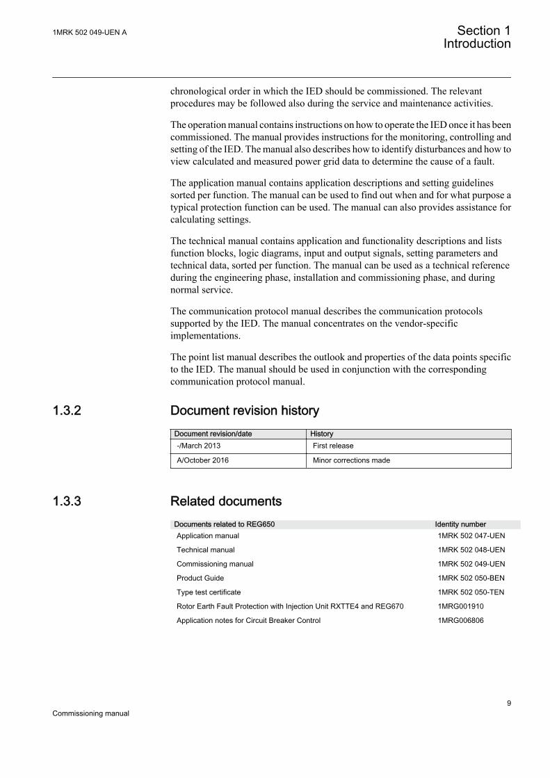
chronological order in which the IED should be commissioned. The relevantprocedures may be followed also during the service and maintenance activities.
The operation manual contains instructions on how to operate the IED once it has beencommissioned. The manual provides instructions for the monitoring, controlling andsetting of the IED. The manual also describes how to identify disturbances and how toview calculated and measured power grid data to determine the cause of a fault.
The application manual contains application descriptions and setting guidelinessorted per function. The manual can be used to find out when and for what purpose atypical protection function can be used. The manual can also provides assistance forcalculating settings.
The technical manual contains application and functionality descriptions and listsfunction blocks, logic diagrams, input and output signals, setting parameters andtechnical data, sorted per function. The manual can be used as a technical referenceduring the engineering phase, installation and commissioning phase, and duringnormal service.
The communication protocol manual describes the communication protocolssupported by the IED. The manual concentrates on the vendor-specificimplementations.
The point list manual describes the outlook and properties of the data points specificto the IED. The manual should be used in conjunction with the correspondingcommunication protocol manual.
1.3.2 Document revision historyDocument revision/date History-/March 2013 First release
A/October 2016 Minor corrections made
1.3.3 Related documentsDocuments related to REG650 Identity numberApplication manual 1MRK 502 047-UEN
Technical manual 1MRK 502 048-UEN
Commissioning manual 1MRK 502 049-UEN
Product Guide 1MRK 502 050-BEN
Type test certificate 1MRK 502 050-TEN
Rotor Earth Fault Protection with Injection Unit RXTTE4 and REG670 1MRG001910
Application notes for Circuit Breaker Control 1MRG006806
1MRK 502 049-UEN A Section 1Introduction
9Commissioning manual
650 series manuals Identity numberCommunication protocol manual, DNP 3.0 1MRK 511 280-UEN
Communication protocol manual, IEC 61850–8–1 1MRK 511 281-UEN
Communication protocol manual, IEC 60870-5-103 1MRK 511 282-UEN
Cyber Security deployment guidelines 1MRK 511 285-UEN
Point list manual, DNP 3.0 1MRK 511 283-UEN
Engineering manual 1MRK 511 284-UEN
Operation manual 1MRK 500 096-UEN
Installation manual 1MRK 514 016-UEN
Accessories, 650 series 1MRK 513 023-BEN
MICS 1MRG 010 656
PICS 1MRG 010 660
PIXIT 1MRG 010 658
1.4 Symbols and conventions
1.4.1 Symbols
The electrical warning icon indicates the presence of a hazard whichcould result in electrical shock.
The warning icon indicates the presence of a hazard which couldresult in personal injury.
The caution icon indicates important information or warning relatedto the concept discussed in the text. It might indicate the presence ofa hazard which could result in corruption of software or damage toequipment or property.
The information icon alerts the reader of important facts andconditions.
The tip icon indicates advice on, for example, how to design yourproject or how to use a certain function.
Although warning hazards are related to personal injury, it is necessary to understandthat under certain operational conditions, operation of damaged equipment may result
Section 1 1MRK 502 049-UEN AIntroduction
10Commissioning manual

in degraded process performance leading to personal injury or death. It is importantthat the user fully complies with all warning and cautionary notices.
1.4.2 Document conventions
• Abbreviations and acronyms in this manual are spelled out in the glossary. Theglossary also contains definitions of important terms.
• Push button navigation in the LHMI menu structure is presented by using thepush button icons.For example, to navigate between the options, use and .
• HMI menu paths are presented in bold.For example, select Main menu/Settings.
• LHMI messages are shown in Courier font.For example, to save the changes in non-volatile memory, select Yes and press
.• Parameter names are shown in italics.
For example, the function can be enabled and disabled with the Operation setting.• Each function block symbol shows the available input/output signal.
• the character ^ in front of an input/output signal name indicates that thesignal name may be customized using the PCM600 software.
• the character * after an input/output signal name indicates that the signalmust be connected to another function block in the applicationconfiguration to achieve a valid application configuration.
1MRK 502 049-UEN A Section 1Introduction
11Commissioning manual

12

Section 2 Available functions
Note that not all functions included in the tables below havecommissioning information available.
2.1 Main protection functions
IEC 61850 orFunction name
ANSI Function description Generator
REG
650
REG
650
(B01
)G
en d
iff
REG
650
(B05
)G
en+T
rafo
diff
Differential protection
T3WPDIF 87T Transformer differential protection, three winding 0–1 1
REFPDIF 87N Restricted earth fault protection, low impedance 0–1
HZPDIF 87 1Ph High impedance differential protection 0–1 1 1
GENPDIF 87G Generator differential protection 0–1 1
Impedance protection
ZMRPSB 68 Power swing detection 0–1
ZGCPDIS 21G Underimpedance protection for generators and transformers 0–1 1 1
LEXPDIS 40 Loss of excitation 0–1 1 1
OOSPPAM 78 Out-of-step protection 0–1 1 1
LEPDIS Load encroachment 0–1 1 1
1MRK 502 049-UEN A Section 2Available functions
13Commissioning manual

2.2 Back-up protection functions
IEC 61850 orFunction name
ANSI Function description Generator
REG
650
REG
650
(B01
)G
en d
iff
REG
650
(B05
)G
en+T
rafo
diff
Current protection
OC4PTOC 51/67 Four step phase overcurrent protection, 3-phase output 0–2 2 2
EF4PTOC 51N/67N Four step residual overcurrent protection, zero/negativesequence direction
0–2 2 2
SDEPSDE 67N Sensitive directional residual overcurrent and powerprotection
0–1 1 1
TRPTTR 49 Thermal overload protection, two time constants 0–2 2 2
CCRBRF 50BF Breaker failure protection, 3–phase activation and output 0–1 1 1
CCRPLD 52PD Pole discordance protection 0–1 1 1
GUPPDUP 37 Directional underpower protection 0–1 1 1
GOPPDOP 32 Directional overpower protection 0–2 2 2
AEGGAPC 50AE Accidental energizing protection for synchronous generator 1 1 1
NS2PTOC 46I2 Negative-sequence time overcurrent protection formachines
1 1 1
VRPVOC 51V Voltage-restrained time overcurrent protection 1 1 1
Voltage protection
UV2PTUV 27 Two step undervoltage protection 0–1 1 1
OV2PTOV 59 Two step overvoltage protection 0–1 1 1
ROV2PTOV 59N Two step residual overvoltage protection 0–2 2 2
OEXPVPH 24 Overexcitation protection 0–1 1 1
STEFPHIZ 59THD 100% Stator earth fault protection, 3rd harmonic based 0–1 1 1
Frequency protection
SAPTUF 81 Underfrequency function 0–4 4 4
SAPTOF 81 Overfrequency function 0–4 4 4
SAPFRC 81 Rate-of-change frequency protection 0–2 2 2
Section 2 1MRK 502 049-UEN AAvailable functions
14Commissioning manual

2.3 Control and monitoring functions
IEC 61850 or Functionname
ANSI Function description Generator
REG
650
REG
650
(B01
)G
en d
iff
REG
650
(B05
)G
en+T
rafo
diff
Control
SESRSYN 25 Synchrocheck, energizing check, and synchronizing 0–1 1 1
SLGGIO Logic Rotating Switch for function selection and LHMIpresentation
15 15 15
VSGGIO Selector mini switch 20 20 20
DPGGIO IEC 61850 generic communication I/O functions doublepoint
16 16 16
SPC8GGIO Single point generic control 8 signals 5 5 5
AUTOBITS AutomationBits, command function for DNP3.0 3 3 3
I103CMD Function commands for IEC60870-5-103 1 1 1
I103IEDCMD IED commands for IEC60870-5-103 1 1 1
I103USRCMD Function commands user defined for IEC60870-5-103 4 4 4
I103GENCMD Function commands generic for IEC60870-5-103 50 50 50
I103POSCMD IED commands with position and select forIEC60870-5-103
50 50 50
Apparatus control and Interlocking
APC8 Apparatus control for single bay, max 8 app. (1CB) incl.interlocking
0–1
SCILO 3 Logical node for interlocking
BB_ES 3 Interlocking for busbar earthing switch
A1A2_BS 3 Interlocking for bus-section breaker
A1A2_DC 3 Interlocking for bus-section disconnector
ABC_BC 3 Interlocking for bus-coupler bay
BH_CONN 3 Interlocking for 1 1/2 breaker diameter
BH_LINE_A 3 Interlocking for 1 1/2 breaker diameter
BH_LINE_B 3 Interlocking for 1 1/2 breaker diameter
DB_BUS_A 3 Interlocking for double CB bay
DB_BUS_B 3 Interlocking for double CB bay
DB_LINE 3 Interlocking for double CB bay
ABC_LINE 3 Interlocking for line bay
AB_TRAFO 3 Interlocking for transformer bay
SCSWI Switch controller
QCBAY Bay control 1 1 1
LOCREM Handling of LR-switch positions 1 1 1
Table continues on next page
1MRK 502 049-UEN A Section 2Available functions
15Commissioning manual

IEC 61850 or Functionname
ANSI Function description Generator
REG
650
REG
650
(B01
)G
en d
iff
REG
650
(B05
)G
en+T
rafo
diff
LOCREMCTRL LHMI control of Permitted Source To Operate (PSTO) 1 1 1
CBC1 Circuit breaker control for 1CB 0–1 1
CBC2 Circuit breaker control for 2CB 0–1 1
Secondary system supervision
SDDRFUF Fuse failure supervision 0–1 1 1
TCSSCBR Breaker close/trip circuit monitoring 3 3 3
Logic
SMPPTRC 94 Tripping logic, common 3–phase output 1–6 6 6
TMAGGIO Trip matrix logic 12 12 12
OR Configurable logic blocks 283 283 283
INVERTER Configurable logic blocks 140 140 140
PULSETIMER Configurable logic blocks 40 40 40
GATE Configurable logic blocks 40 40 40
XOR Configurable logic blocks 40 40 40
LOOPDELAY Configurable logic blocks 40 40 40
TIMERSET Configurable logic blocks 40 40 40
AND Configurable logic blocks 280 280 280
SRMEMORY Configurable logic blocks 40 40 40
RSMEMORY Configurable logic blocks 40 40 40
Q/T Configurable logic blocks Q/T 0–1
ANDQT Configurable logic blocks Q/T 0–120
ORQT Configurable logic blocks Q/T 0–120
INVERTERQT Configurable logic blocks Q/T 0–120
XORQT Configurable logic blocks Q/T 0–40
SRMEMORYQT Configurable logic blocks Q/T 0–40
RSMEMORYQT Configurable logic blocks Q/T 0–40
TIMERSETQT Configurable logic blocks Q/T 0–40
PULSETIMERQT Configurable logic blocks Q/T 0–40
INVALIDQT Configurable logic blocks Q/T 0–12
INDCOMBSPQT Configurable logic blocks Q/T 0–20
INDEXTSPQT Configurable logic blocks Q/T 0–20
FXDSIGN Fixed signal function block 1 1 1
B16I Boolean 16 to Integer conversion 16 16 16
B16IFCVI Boolean 16 to Integer conversion with logic noderepresentation
16 16 16
IB16A Integer to Boolean 16 conversion 16 16 16
Table continues on next page
Section 2 1MRK 502 049-UEN AAvailable functions
16Commissioning manual

IEC 61850 or Functionname
ANSI Function description Generator
REG
650
REG
650
(B01
)G
en d
iff
REG
650
(B05
)G
en+T
rafo
diff
IB16FCVB Integer to Boolean 16 conversion with logic noderepresentation
16 16 16
TEIGGIO Elapsed time integrator with limit transgression andoverflow supervision
12 12 12
Monitoring
CVMMXN Measurements 6 6 6
CMMXU Phase current measurement 10 10 10
VMMXU Phase-phase voltage measurement 6 6 6
CMSQI Current sequence component measurement 6 6 6
VMSQI Voltage sequence measurement 6 6 6
VNMMXU Phase-neutral voltage measurement 6 6 6
AISVBAS Function block for service values presentation of theanalog inputs
1 1 1
TM_P_P2 Function block for service values presentation of primaryanalog inputs 600TRM
1 1 1
AM_P_P4 Function block for service values presentation of primaryanalog inputs 600AIM
1 1 1
TM_S_P2 Function block for service values presentation ofsecondary analog inputs 600TRM
1 1 1
AM_S_P4 Function block for service values presentation ofsecondary analog inputs 600AIM
1 1 1
CNTGGIO Event counter 5 5 5
L4UFCNT Event counter with limit supervision 12 12 12
DRPRDRE Disturbance report 1 1 1
AnRADR Analog input signals 4 4 4
BnRBDR Binary input signals 6 6 6
SPGGIO IEC 61850 generic communication I/O functions 64 64 64
SP16GGIO IEC 61850 generic communication I/O functions 16inputs
16 16 16
MVGGIO IEC 61850 generic communication I/O functions 16 16 16
MVEXP Measured value expander block 66 66 66
SPVNZBAT Station battery supervision 0–1 1 1
SSIMG 63 Insulation gas monitoring function 0–2 2 2
SSIML 71 Insulation liquid monitoring function 0–2 2 2
SSCBR Circuit breaker condition monitoring 0–1 1 1
I103MEAS Measurands for IEC60870-5-103 1 1 1
I103MEASUSR Measurands user defined signals for IEC60870-5-103 3 3 3
I103AR Function status auto-recloser for IEC60870-5-103 1 1 1
Table continues on next page
1MRK 502 049-UEN A Section 2Available functions
17Commissioning manual
IEC 61850 or Functionname
ANSI Function description Generator
REG
650
REG
650
(B01
)G
en d
iff
REG
650
(B05
)G
en+T
rafo
diff
I103EF Function status earth-fault for IEC60870-5-103 1 1 1
I103FLTPROT Function status fault protection for IEC60870-5-103 1 1 1
I103IED IED status for IEC60870-5-103 1 1 1
I103SUPERV Supervison status for IEC60870-5-103 1 1 1
I103USRDEF Status for user defined signals for IEC60870-5-103 20 20 20
Metering
PCGGIO Pulse counter 16 16 16
ETPMMTR Function for energy calculation and demand handling 3 3 3
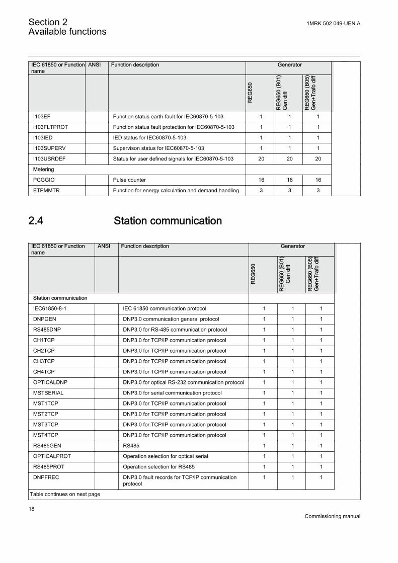
2.4 Station communication
IEC 61850 or Functionname
ANSI Function description Generator
R
EG65
0
REG
650
(B01
)G
en d
iff
REG
650
(B05
)G
en+T
rafo
diff
Station communication
IEC61850-8-1 IEC 61850 communication protocol 1 1 1
DNPGEN DNP3.0 communication general protocol 1 1 1
RS485DNP DNP3.0 for RS-485 communication protocol 1 1 1
CH1TCP DNP3.0 for TCP/IP communication protocol 1 1 1
CH2TCP DNP3.0 for TCP/IP communication protocol 1 1 1
CH3TCP DNP3.0 for TCP/IP communication protocol 1 1 1
CH4TCP DNP3.0 for TCP/IP communication protocol 1 1 1
OPTICALDNP DNP3.0 for optical RS-232 communication protocol 1 1 1
MSTSERIAL DNP3.0 for serial communication protocol 1 1 1
MST1TCP DNP3.0 for TCP/IP communication protocol 1 1 1
MST2TCP DNP3.0 for TCP/IP communication protocol 1 1 1
MST3TCP DNP3.0 for TCP/IP communication protocol 1 1 1
MST4TCP DNP3.0 for TCP/IP communication protocol 1 1 1
RS485GEN RS485 1 1 1
OPTICALPROT Operation selection for optical serial 1 1 1
RS485PROT Operation selection for RS485 1 1 1
DNPFREC DNP3.0 fault records for TCP/IP communicationprotocol
1 1 1
Table continues on next page
Section 2 1MRK 502 049-UEN AAvailable functions
18Commissioning manual
IEC 61850 or Functionname
ANSI Function description Generator
REG
650
REG
650
(B01
)G
en d
iff
REG
650
(B05
)G
en+T
rafo
diff
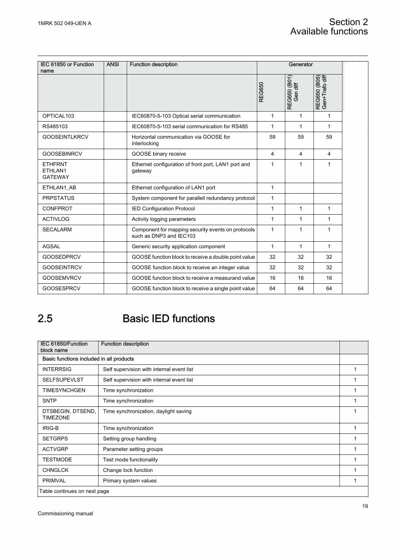
OPTICAL103 IEC60870-5-103 Optical serial communication 1 1 1
RS485103 IEC60870-5-103 serial communication for RS485 1 1 1
GOOSEINTLKRCV Horizontal communication via GOOSE forinterlocking
59 59 59
GOOSEBINRCV GOOSE binary receive 4 4 4
ETHFRNTETHLAN1GATEWAY
Ethernet configuration of front port, LAN1 port andgateway
1 1 1
ETHLAN1_AB Ethernet configuration of LAN1 port 1
PRPSTATUS System component for parallell redundancy protocol 1
CONFPROT IED Configuration Protocol 1 1 1
ACTIVLOG Activity logging parameters 1 1 1
SECALARM Component for mapping security events on protocolssuch as DNP3 and IEC103
1 1 1
AGSAL Generic security application component 1 1 1
GOOSEDPRCV GOOSE function block to receive a double point value 32 32 32
GOOSEINTRCV GOOSE function block to receive an integer value 32 32 32
GOOSEMVRCV GOOSE function block to receive a measurand value 16 16 16
GOOSESPRCV GOOSE function block to receive a single point value 64 64 64
2.5 Basic IED functions
IEC 61850/Functionblock name
Function description
Basic functions included in all products
INTERRSIG Self supervision with internal event list 1
SELFSUPEVLST Self supervision with internal event list 1
TIMESYNCHGEN Time synchronization 1
SNTP Time synchronization 1
DTSBEGIN, DTSEND,TIMEZONE
Time synchronization, daylight saving 1
IRIG-B Time synchronization 1
SETGRPS Setting group handling 1
ACTVGRP Parameter setting groups 1
TESTMODE Test mode functionality 1
CHNGLCK Change lock function 1
PRIMVAL Primary system values 1
Table continues on next page
1MRK 502 049-UEN A Section 2Available functions
19Commissioning manual

IEC 61850/Functionblock name
Function description
SMAI_20_1 -SMAI_20_12
Signal matrix for analog inputs 2
3PHSUM Summation block 3 phase 12
GBASVAL Global base values for settings 6
ATHSTAT Authority status 1
ATHCHCK Authority check 1
AUTHMAN Authority management 1
FTPACCS FTPS access with password 1
DOSFRNT Denial of service, frame rate control for front port 1
DOSLAN1 Denial of service, frame rate control for LAN1A and LAN1B ports 1
DOSSCKT Denial of service, socket flow control 1
Section 2 1MRK 502 049-UEN AAvailable functions
20Commissioning manual
Section 3 Starting up
3.1 Factory and site acceptance testing
Testing the proper IED operation is carried out at different occasions, for example:
• Acceptance testing• Commissioning testing• Maintenance testing
This manual describes the workflow and the steps to carry out the commissioningtesting.
Factory acceptance testing (FAT) is typically done to verify that the IED and itscorresponding configuration meet the requirements of the utility or industry. This testis the most complex and in depth, as it is done to familiarize the user with a newproduct or to verify a new configuration. The complexity of this testing depends onseveral factors, such as:
• New IED type• New configuration• Modified configuration
Site acceptance testing (SAT or commissioning testing) is typically done to verify thatthe installed IED is correctly set and connected to the power system. SAT requires thatthe acceptance testing has been performed and that the application configuration isverified.
Maintenance testing is a periodic verification that the IED is healthy and has correctsettings, depending on changes in the power system. There are also other types ofmaintenance testing.
3.2 Commissioning checklist
Before starting up commissioning at site, check that the following items are available.
• Single line diagram• Protection block diagram• Circuit diagram• Setting list and configuration• RJ-45 Ethernet cable (CAT 5)• Three-phase test kit or other test equipment depending on the complexity of the
configuration and functions to be tested.
1MRK 502 049-UEN A Section 3Starting up
21Commissioning manual

• PC with PCM600 installed along with the connectivity packages correspondingto the IEDs to be tested.
• Administration rights on the PC, to set up IP addresses• Product documentation (engineering manual, installation manual,
commissioning manual, operation manual, technical manual and communicationprotocol manual)
3.3 Checking the power supply
Check that the auxiliary supply voltage remains within the permissible input voltagerange under all operating conditions. Check that the polarity is correct beforepowering the IED.
3.4 Energizing the IED
3.4.1 Checking the IED operation
Check all connections to external circuitry to ensure correct installation, beforeenergizing the IED and carrying out the commissioning procedures.
Energize the power supply of the IED to start it up. This could be done in a number ofways, from energizing a whole cubicle to energizing a single IED. Set the IED time ifno time synchronization source is configured. Check the self-supervision function inMain menu/Diagnostics/Internal events or Main menu/Diagnostics/IED status/General menu in local HMI to verify that the IED is functioning properly.
3.4.2 IED start-up sequence
The following sequence is expected when the IED is energized.
• The green Ready LED starts flashing instantly and the ABB logo is shown on theLCD.
• After approximately 30 seconds, "Starting" is shown on the LCD.• Within 90 seconds, the main menu is shown on the LCD and the green Ready
LED shows a steady light, which indicates a successful startup.
The startup time depends on the size of the application configuration.Application configurations with less functionality have shorterstartup times.
If the green Ready LED continues to flash after startup, the IED has detected aninternal error. Navigate via Main menu/Diagnostics/IED status/General toinvestigate the error description.
Section 3 1MRK 502 049-UEN AStarting up
22Commissioning manual

3.5 Setting up communication between PCM600 and theIED
The communication between the IED and PCM600 is independent of thecommunication protocol used within the substation or to the NCC.
The communication media is always Ethernet and the used protocol is TCP/IP.
Each IED has an RJ-45 Ethernet interface connector on the front. The front Ethernetconnector shall be used for communication with PCM600..
When an Ethernet-based station protocol is used, PCM600 communication can usethe same Ethernet port and IP address.
To connect PCM600 to the IED, two basic variants must be considered.
• Direct point-to-point link between PCM600 and the IED front port.• Indirect link via a station LAN or from remote via a network.
The physical connection and the IP address must be configured in both cases to enablecommunication.
The communication procedures are the same in both cases.
1. If needed, set the IP address for the IEDs.2. Set up the PC or workstation for a direct link (point-to-point), or3. Connect the PC or workstation to the LAN/WAN network.4. Configure the IED IP addresses in the PCM600 project for each IED to match the
IP addresses of the physical IEDs.
Setting up IP addressesThe IP address and the corresponding mask must be set via the LHMI for eachavailable Ethernet interface in the IED. Each Ethernet interface has a default factoryIP address when the IED is delivered. This is not given when an additional Ethernetinterface is installed or an interface is replaced.
• The default IP address for the IED front port is 10.1.150.3 and the correspondingsubnetwork mask is 255.255.255.0, which can be set via the local HMI path Mainmenu/Configuration/Communication/TCP-IP configuration/ETHFRNT:1.
Setting up the PC or workstation for point-to-point access to IEDs frontportA special cable is needed to connect two physical Ethernet interfaces together withouta hub, router, bridge or switch in between. The Tx and Rx signal wires must be crossedin the cable to connect Tx with Rx on the other side and vice versa. These cables areknown as cross over cables. The maximum length is 2 m. The connector type isRJ-45.
1MRK 502 049-UEN A Section 3Starting up
23Commissioning manual

IEC09000096-2-en.vsd
Tx Tx
Rx Rx
RJ-45IEDPCM600
IEC09000096 V2 EN
Figure 2: Point-to-point link between IED and PCM600 using a null-modemcable
The following description is an example valid for standard PCs using MicrosoftWindows operating system. The example is taken from a Laptop with one Ethernetinterface.
Administrator rights are required to change the PC communicationsetup. Some PCs have the feature to automatically detect that Txsignals from the IED are received on the Tx pin on the PC. Thus, astraight (standard) Ethernet cable can be used.
When a PC is connected to the IED and the setting DHCPServer is set to On via thelocal HMI path Main menu/Configuration/Communication/TCP-IPconfiguration/ETHFRNT:1/DHCPServer, the IEDs DHCP server for the front portassigns an IP address for the PC. The PC must be configured to obtain its IP addressautomatically as described in the following procedure.
1. Select Search programs and files in the Start menu in Windows.
Section 3 1MRK 502 049-UEN AStarting up
24Commissioning manual

IEC13000057-1-en.vsd
IEC13000057 V1 EN
Figure 3: Select: Search programs and files
2. Type View network connections and click on the View network connectionsicon.
1MRK 502 049-UEN A Section 3Starting up
25Commissioning manual

IEC13000058-1-en.vsd
IEC13000058 V1 EN
Figure 4: Click View network connections
3. Right-click and select Properties.
IEC13000059-1-en.vsd
IEC13000059 V1 EN
Figure 5: Right-click Local Area Connection and select Properties
4. Select the TCP/IPv4 protocol from the list of configured components using thisconnection and click Properties.
Section 3 1MRK 502 049-UEN AStarting up
26Commissioning manual

IEC13000060-1-en.vsd
IEC13000060 V1 EN
Figure 6: Select the TCP/IPv4 protocol and open Properties
5. Select Obtain an IP address automatically if the parameter DHCPServer is setto On in the IED.
IEC13000061-1-en.vsd
IEC13000061 V1 EN
Figure 7: Select: Obtain an IP address automatically
6. Select Use the following IP address and define IP address and Subnet mask ifthe front port is used and if the IP address is not set to be obtained automatically
1MRK 502 049-UEN A Section 3Starting up
27Commissioning manual
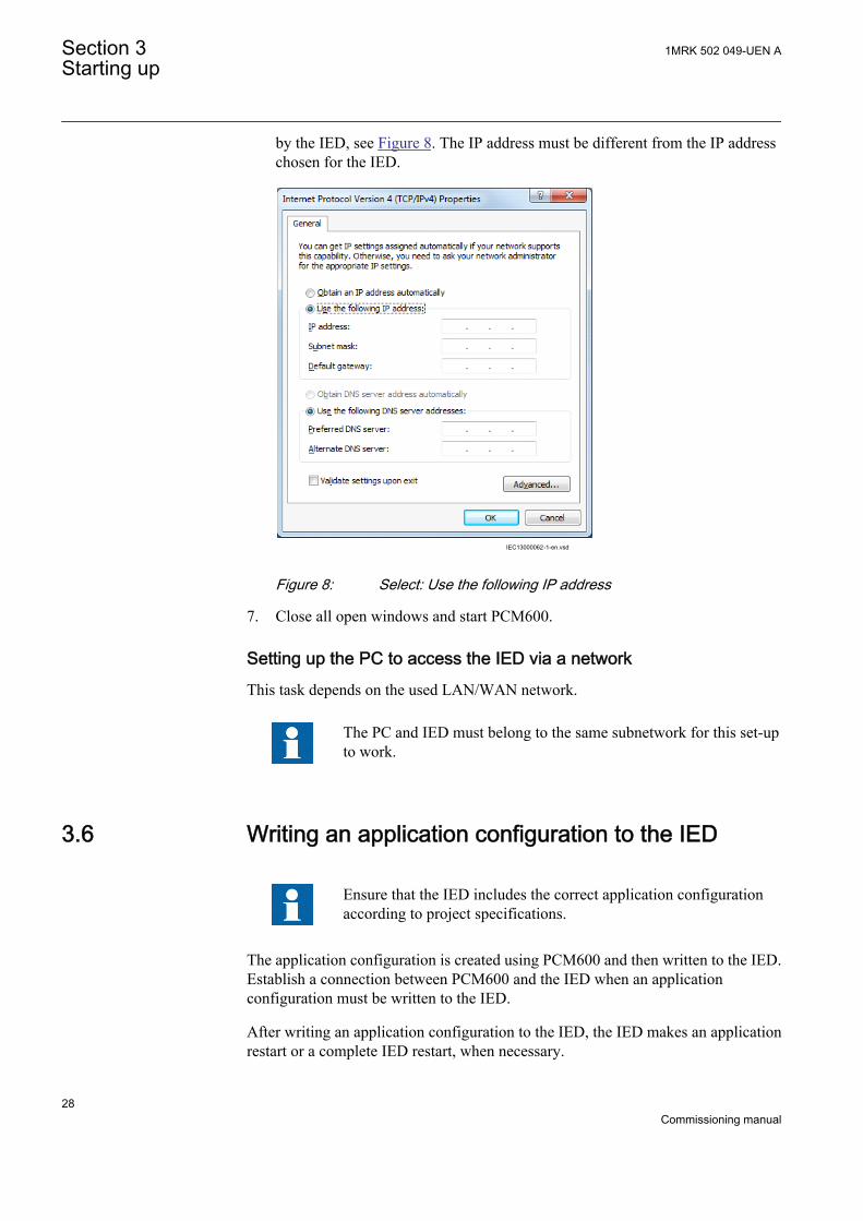
by the IED, see Figure 8. The IP address must be different from the IP addresschosen for the IED.
IEC13000062-1-en.vsd
IEC13000062 V1 EN
Figure 8: Select: Use the following IP address
7. Close all open windows and start PCM600.
Setting up the PC to access the IED via a networkThis task depends on the used LAN/WAN network.
The PC and IED must belong to the same subnetwork for this set-upto work.
3.6 Writing an application configuration to the IED
Ensure that the IED includes the correct application configurationaccording to project specifications.
The application configuration is created using PCM600 and then written to the IED.Establish a connection between PCM600 and the IED when an applicationconfiguration must be written to the IED.
After writing an application configuration to the IED, the IED makes an applicationrestart or a complete IED restart, when necessary.
Section 3 1MRK 502 049-UEN AStarting up
28Commissioning manual
The IED does not restart after reconfiguring IEC61850 (regardless ofwhether the protocol is enabled or disabled).
Be sure to set the correct technical key in both the IED and PCM600to prevent writing an application configuration to a wrong IED.
See the engineering manual for information on how to create ormodify an application configuration and how to write to the IED.
3.7 Checking CT circuits
Check that the wiring is in strict accordance with the suppliedconnection diagram.
• Primary injection test to verify the current ratio of the CT, the correct wiring upto the protection IED and correct phase sequence connection (that is L1, L2, L3.)
• CT secondary loop resistance measurement to confirm that the currenttransformer secondary loop DC resistance is within specification and that thereare no high resistance joints in the CT winding or wiring.
• Earthing check of the individual CT secondary circuits to verify that each three-phase set of main CTs is properly connected to the station earth and only at oneelectrical point.
• Insulation resistance check.
CT and VT connectors are pre-coded, and the CT and VT connectormarkings are different. For more information, see the installationmanual.
Both the primary and the secondary sides must be disconnected fromthe line and the IED when plotting the excitation characteristics.
3.8 Checking VT circuits
Check that the wiring is in strict accordance with the supplied connection diagram.
1MRK 502 049-UEN A Section 3Starting up
29Commissioning manual

Correct possible errors before continuing to test the circuitry.
Test the circuitry.
• Polarity check• VT circuit voltage measurement (primary injection test)• Earthing check• Phase relationship• Insulation resistance check
The polarity check verifies the integrity of circuits and the phase relationships. Thecheck must be performed as close to the IED as possible.
The primary injection test verifies the VT ratio and the wiring all the way from theprimary system to the IED. Injection must be performed for each phase-to-neutralcircuit and each phase-to-phase pair. In each case, voltages in all phases and neutralare measured.
3.9 Using the RTXP test switch
The RTXP test switch is designed to provide the means of safe testing of the IED. Thisis achieved by the electromechanical design of the test switch and test plug handle.When the test plug handle is inserted, it first blocks the trip and alarm circuits then itshort circuits the CT secondary circuit and opens the VT secondary circuits makingthe IED available for secondary injection.
When pulled out, the test handle is mechanically stopped in half withdrawn position.In this position, the current and voltage enter the protection, but the alarm and tripcircuits are still isolated. Before removing the test handle, check that no trip or alarmsare present in the IED.
Not until the test handle is completely removed, the trip and alarm circuits are restoredfor operation.
Verify that the contact sockets have been crimped correctly and thatthey are fully inserted by tugging on the wires. Never do this withcurrent circuits in service.
Current circuit
1. Verify that the contacts are of current circuit type.2. Verify that the short circuit jumpers are located in the correct slots.
Voltage circuit
Section 3 1MRK 502 049-UEN AStarting up
30Commissioning manual

1. Verify that the contacts are of voltage circuit type.2. Check that no short circuit jumpers are located in the slots dedicated for voltage.
Trip and alarm circuits
1. Check that the correct types of contacts are used.
3.10 Checking binary input and output circuits
3.10.1 Binary input circuits
Preferably, disconnect the binary input connector from the binary input cards. Checkall connected signals so that both input level and polarity are in accordance with theIED specifications.
3.10.2 Binary output circuits
Preferably, disconnect the binary output connector from the binary output cards.Check all connected signals so that both load and polarity are in accordance with IEDspecifications.
3.11 Checking optical connections
Check that the Tx and Rx optical connections are correct.
An IED equipped with optical connections requires a minimum depthof 180 mm for plastic fiber cables and 275 mm for glass fiber cables.Check the allowed minimum bending radius from the optical cablemanufacturer.
1MRK 502 049-UEN A Section 3Starting up
31Commissioning manual

32

Section 4 Establishing connection and verifying theIEC 61850 station communication
4.1 Setting the station communication
To enable IEC 61850 station communication:
• The IEC 61850-8-1 station communication functionality must be on in the localHMI. Navigate to Main menu/Configuration/Communication/Stationcommunication/IEC61850-8-1:1 and set the Operation parameter to On.
• To enable GOOSE communication the Operation parameter for thecorresponding GOOSE function blocks (GOOSEBINRCV andGOOSEINTLKRCV) must be set to On in the application configuration.
• To enable GOOSE communication via the front port the parameterPortSelGOOSE in Main menu/Configuration/Communication/Stationcommunication/IEC61850-8-1:1 must be set to Front. To enable GOOSEcommunication via rear port the parameter PortSelGOOSE must be set to LAN1.
• To enable MMS communication via the rear port the parameter PortSelMMS inMain menu/Configuration/Communication/Station communication/IEC61850-8-1:1 must be set to LAN1.
4.2 Verifying the station communication
Connect your PC to the substation network and ping the connected IED and theSubstation Master PC, to verify that the communication is working (up to the transportlayer).
The best way to verify the communication up to the application layer is to use protocolanalyzer connected to the substation bus, and monitor the communication.
1MRK 502 049-UEN A Section 4Establishing connection and verifying the IEC 61850 station communication
33Commissioning manual

34
Section 5 Testing IED operation
5.1 Preparing the IED to verify settings
If a test switch is included, start preparation by making the necessary connections tothe test switch. This means connecting the test equipment according to a specific anddesignated IED terminal diagram.
Put the IED into the test mode to facilitate the test of individual functions and preventunwanted operation caused by other functions. The busbar differential protection isnot included in the test mode and is not prevented to operate during the test operations.The test switch should then be connected to the IED.
Verify that analog input signals from the analog input module are measured andrecorded correctly by injecting currents and voltages required by the specific IED.
To make testing even more effective, use PCM600. PCM600 includes the Signalmonitoring tool, which is useful in reading the individual currents and voltages, theiramplitudes and phase angles. In addition, PCM600 contains the Disturbance handlingtool. The content of reports generated by the Disturbance handling tool can beconfigured which makes the work more efficient. For example, the tool may beconfigured to only show time tagged events and to exclude analog information and soon.
Check the disturbance report settings to ensure that the indications are correct.
For test functions and test and signal parameter names, see the technical manual. Thecorrect initiation of the disturbance recorder is made on start and/or release or tripfrom a function. Also check that the wanted recordings of analog (real and calculated)and binary signals are achieved.
The IEDs in the 650 series can have between 1 and 4 individual parameter settinggroups prepared with full sets of different parameters for all functions. The purpose ofthese groups is to be able to handle different power system load conditions to optimizethe parameters settings of the different functions for these different power systemsconditions (for example summer/winter and day/night).
Parameters can be entered into different setting groups. Make sure totest functions for the same parameter setting group. If needed, repeatthe tests for all different setting groups used. The difference betweentesting the first parameter setting group and the remaining is that thereis no need for testing the connections.
1MRK 502 049-UEN A Section 5Testing IED operation
35Commissioning manual

During testing, observe that the right testing method, that corresponds to the actualparameters set in the activated parameter setting group, is used.
In the local HMI the sensitive directional earth fault protection SDEPSDE parametergroup 4 is active indicated by the * next to #4 and the test of the SDEPSDE must beperformed according to the instructions given for the setting OpMode and settingvalue 3I03U0cosfi.
Set and configure the function(s) before testing. Most functions are highly flexible andpermit a choice of functional and tripping modes. The various modes are checked atthe factory as part of the design verification. In certain cases, only modes with a highprobability of coming into operation need to be checked when commissioned to verifythe configuration and settings.
Requirements for testing the function.
• Calculated settings• Valid configuration diagram for the IED• Valid terminal diagram for the IED• Technical manual• Three-phase test equipment
Content of the technical manual.
• Application and functionality summaries• Function blocks• Logic diagrams• Input and output signals• A list of setting parameters• Technical data for the function
The test equipment should be able to provide a three-phase supply of currents andthree-phase voltage. The magnitude and angle of currents (and voltages) should bepossible to vary. Check that the IED is prepared for test before starting the test session.Consider the logic diagram of the function when performing the test.
The response from a test can be viewed in different ways.
• Binary output signals• Service values in the local HMI (logical signal or phasors)• Using the online mode in the PCM600 configuration software
Do not switch off the auxiliary power supply to the IED beforechanges, for example, setting parameter or local/remote control statechanges are saved.
A mechanism for limiting the number of writings per time period is included in theIED to prevent the flash memory to be worn out due to too many writings. As a
Section 5 1MRK 502 049-UEN ATesting IED operation
36Commissioning manual
consequence it may take up to an hour to save changes. If the auxiliary power isinterrupted before a change is saved, that change is lost.
5.2 Activating the test mode
Put the IED into the test mode before testing. The test mode blocks all protectionfunctions and some of the control functions in the IED, and the individual functions tobe tested can be unblocked to prevent unwanted operation caused by other functions.In this way, it is possible to test slower back-up measuring functions without theinterference from faster measuring functions. The busbar differential protection is notincluded in the test mode and is not prevented to operate during the test operations.The test switch should then be connected to the IED.Test mode is indicated when theyellow StartLED flashes.
1. Select Main menu/Tests/IED test mode/TESTMODE:12. Set parameter TestMode to On.3. Save the changes.
As a consequence, the yellow startLED starts flashing as a reminder and remainsflashing until the test mode is switched off.
5.3 Preparing the connection to the test equipment
The IED can be equipped with a test switch of type RTXP8, RTXP18 or RTXP24. Thetest switch and its associated test plug handle (RTXH8, RTXH18 or RTXH24) are apart of the COMBITEST system, which provides secure and convenient testing of theIED.
When using the COMBITEST, preparations for testing are automatically carried outin the proper sequence, that is, for example, blocking of tripping circuits, shortcircuiting of CT’s, opening of voltage circuits, making IED terminals available forsecondary injection. Terminals 1 and 8, 1 and 18 as well as 1 and 12 of the test switchesRTXP8, RTXP18 and RTXP24 respectively are not disconnected as they supply DCpower to the protection IED.
The RTXH test-plug handle leads may be connected to any type of test equipment orinstrument. When a number of protection IEDs of the same type are tested, the test-plug handle only needs to be moved from the test switch of one protection IED to thetest switch of the other, without altering the previous connections.
Use COMBITEST test system to prevent unwanted tripping when the handle iswithdrawn, since latches on the handle secure it in the half withdrawn position. In thisposition, all voltages and currents are restored and any re-energizing transients aregiven a chance to decay before the trip circuits are restored. When the latches arereleased, the handle can be completely withdrawn from the test switch, restoring thetrip circuits to the protection IED.
1MRK 502 049-UEN A Section 5Testing IED operation
37Commissioning manual

If a test switch is not used, perform measurement according to the provided circuitdiagrams.
Never disconnect the secondary connection of a current transformercircuit without first short-circuiting the transformer's secondarywinding. Operating a current transformer with the secondary windingopen will cause a massive potential build up that may damage thetransformer and cause personal injury.
5.4 Connecting the test equipment to the IED
Connect the test equipment according to the IED specific connection diagram and theneeded input and output signals for the function under test. An example of aconnection is shown in figure 9.
Connect the current and voltage terminals. Pay attention to the current polarity. Makesure that the connection of input and output current terminals and the connection of theresidual current conductor is correct. Check that the input and output logical signalsin the logic diagram for the function under test are connected to the correspondingbinary inputs and outputs of the IED under test.
To ensure correct results, make sure that the IED as well as the testequipment are properly earthed before testing.
IL1IL2IL3IN
UL1UL2UL3
N
IL1IL2IL3
UL1
IN
TRIP
Test
equ
ipm
ent
IEDUL2
UL3NUN
IEC 61850IEC09000643-1-en.vsd
IEC09000643 V1 EN
Figure 9: Connection example of the test equipment to the IED when testequipment is connected to the transformer input module
Section 5 1MRK 502 049-UEN ATesting IED operation
38Commissioning manual
5.5 Releasing the function to be tested
Release or unblock the function to be tested. This is done to ensure that only thefunction or the chain of functions to be tested are in operation and that other functionsare prevented from operating. Release the tested function(s) by setting thecorresponding Blocked parameter under Function test modes to No in the local HMI.
When testing a function in this blocking feature, remember that not only the actualfunction must be activated, but the whole sequence of interconnected functions (frommeasuring inputs to binary output contacts), including logic must be activated. Beforestarting a new test mode session, scroll through every function to ensure that only thefunction to be tested (and the interconnected ones) have the parameters Blocked andeventually EvDisable set to No and Yes respectively. Remember that a function is alsoblocked if the BLOCK input signal on the corresponding function block is active,which depends on the configuration. Ensure that the logical status of the BLOCKinput signal is equal to 0 for the function to be tested. Event function blocks can alsobe individually blocked to ensure that no events are reported to a remote station duringthe test. This is done by setting the parameter EvDisable to Yes.
Any function is blocked if the corresponding setting in the local HMIunder Main menu/Tests/Function test modes menu remains On,that is, the parameter Blocked is set to Yes and the parameter TestModeunder Main menu/Tests/IED test mode remains active. Allfunctions that were blocked or released in a previous test modesession, that is, the parameter Test mode is set to On, are reset when anew test mode session is started.
Procedure
1. Click the Function test modes menu.The Function test modes menu is located in the local HMI under Main menu/Tests/Function test modes.
2. Browse to the function instance that needs to be released.3. Set parameter Blocked for the selected function to No.
5.6 Verifying analog primary and secondarymeasurement
Verify that the connections are correct and that measuring and scaling is donecorrectly. This is done by injecting current and voltage to the IED.
Apply input signals as needed according to the actual hardware andthe application configuration.
1MRK 502 049-UEN A Section 5Testing IED operation
39Commissioning manual

1. Inject a symmetrical three-phase voltage and current at rated value.2. Compare the injected value with the measured values.
The voltage and current phasor menu in the local HMI is located under Mainmenu/Measurements/Analog primary values and Main menu/Measurements/Analog secondary values.
3. Compare the frequency reading with the set frequency and the direction of thepower.The frequency and active power are located under Main menu/Tests/Functionstatus/Monitoring/CVMMXN/CVMMXN:1/Outputs. Then navigate to thebottom of the list to find the frequency.
Check both analog primary and secondary values, because thenthe CT and VT ratios entered into the IED are also checked.
These checks shall be repeated for Analog primary values.4. Inject an unsymmetrical three-phase voltage and current, to verify that phases
are correctly connected.
If some setting deviates, check the analog input settings under
Main menu/Configuration/Analog modules
Measured values such as current and voltages as well as active, reactive and apparentpower, power factor phase angles as well as positive and negative and zero sequencecurrents and voltages are available in the local HMI under Main menu/Tests/Function status/Monitoring.
Navigate to the measurement function that contains the quantity to be checked.
Table 1: Measurement functions
Function Quantity DescriptionCMMXU IL1 to IL3 amplitude, range and angle
CMSQI 3I0; I1 and I2 amplitude, range and angle
CVMMXN S; P; Q; PF; Ilag; Ilead; U; I and f amplitude, range and angle
VMMXU UL12 to UL31 i.e. phase-to-phase
amplitude, range and angle
VMSQI 3U0; U1 and U2 amplitude, range and angle
VNMMXU UL1 to UL3 i.e. phase-to-neutral amplitude, range and angle
Also the Signal Monitoring tool in PCM600 can be used to read the measured values.In many cases it is more convenient to use PCM600 since, among many things, reportson measured values can be exported from the Signal Monitoring tool to other tools (forexample, MS Excel) for further analysis.
Section 5 1MRK 502 049-UEN ATesting IED operation
40Commissioning manual

5.7 Testing the protection functionality
Each protection function must be tested individually by secondary injection.
• Verify operating levels (trip) and timers.• Verify alarm and blocking signals.• Use the disturbance handling tool in PCM600 to evaluate that the protection
function has received the correct data and responded correctly (signaling andtiming).
• Use the event viewer tool in PCM600 to check that only expected events haveoccurred.
1MRK 502 049-UEN A Section 5Testing IED operation
41Commissioning manual

42

Section 6 Testing functionality
6.1 Testing disturbance report
6.1.1 Introduction
The following sub-functions are included in the disturbance report function:
• Disturbance recorder• Event list• Event recorder• Trip value recorder• Indications
If the disturbance report is set on, then its sub-functions are also set up and so it is notpossible to only switch these sub-functions off. The disturbance report function isswitched off (parameter Operation = Off) in PCM600 or the local HMI under Mainmenu/Settings/IED Settings/Monitoring/Disturbance report/DRPRDRE:1.
6.1.2 Disturbance report settings
When the IED is in test mode, the disturbance report can be made active or inactive.If the disturbance recorder is turned on during test mode, recordings will be made.When test mode is switched off all recordings made during the test session are cleared.
Setting OpModeTest for the control of the disturbance recorder during test mode arelocated on the local HMI under Main menu/Settings/IED Settings/Monitoring/Disturbance report/DRPRDRE:1.
6.2 Identifying the function to test in the technicalreference manual
Use the technical manual to identify function blocks, logic diagrams, input and outputsignals, setting parameters and technical data.
1MRK 502 049-UEN A Section 6Testing functionality
43Commissioning manual
6.3 Testing differential protection functions
6.3.1 Transformer differential protection T3WPDIF
Prepare the IED for verification of settings as outlined in 5.1 "Preparing the IED toverify settings".
Values of the logical signals for T3WPDIF are available on the local HMI under Mainmenu/Tests/Function status/Differential/T3WPDIF(87T,Id)/T3WPDIF:1. TheSignal Monitoring in PCM600 shows the same signals that are available on the localHMI.
6.3.1.1 Verifying the settings
1. Go to Main menu/Test/Function test modes/Differential protection andmake sure that the restricted earth fault protection, low impedance functionREFPDIF is set to Off and that the four step residual overcurrent functionEF4PTOC under Main menu/Test/Function test modes/Current protectionis set to Off, since they are configured to the same current transformer inputs asthe transformer differential protection. Make sure that the transformerdifferential functions T2WPDIF or T3WPDIF are unblocked.
2. Connect the test set for injection of three-phase currents to the current terminalsof the IED, which are connected to the CTs on the HV side of the powertransformer.
3. Increase the current in phase L1 until the protection function operates and notethe operating current.
4. Check that the trip and alarm contacts operate according to the configurationlogic.
5. Decrease the current slowly from operate value and note the reset value.Depending on the power transformer vector group (Yd and so on), the single-phase injection current will be different by a factor k from the three-phase start,see step 7. This factor k can have one of the following three values: 1.0, or 1.5,or 2.0.
6. Check in the same way the function by injecting current in phases L2 and L3respectively. Phase L2 and L3 start shall be the same as for phase L1.
7. Inject a symmetrical three-phase current and note the operate value.8. Connect the timer and set the current to twice the operate value.9. Switch on the current and note the operate time.10. Check in the same way the measuring circuits connected to the CTs on the LV
side and other current inputs to the transformer differential protection.11. Finally check that trip information is stored in the event menu.12. If available on the test set, a second harmonic current of about 20% (assumes
15% setting on I1/I2 ratio parameter) can be added to the fundamental frequencyin phase L1. Increase the current in phase L1 above the start value measured instep 6. Repeat test with current injection in phases L2 and L3 respectively.
Section 6 1MRK 502 049-UEN ATesting functionality
44Commissioning manual
Note that during this test setting SOTFMode must be set to Off.
The balancing of currents flowing into and out of the differential zone istypically checked by primary testing when suitable supply facilities exist on site.Fifth harmonic blocking can be tested in a similar way. Note, the blocking levelfor the fifth harmonic is 10% higher than the I5/I1 Ratio setting.
6.3.1.2 Completing the test
Continue to test another function or end the testing by setting the parameter TestModeto Off under Main menu/Tests/IED test mode/TESTMODE:1. If another functionis tested, then set the parameter Blocked to No under Main menu/Tests/Function testmodes/Differential/T3WPDIF(87T,Id)/T3WPDIF:1 for the function, or for eachindividual function in a chain, to be tested next. Remember to set the parameterBlocked to Yes, for each individual function that has been tested.
6.3.2 Restricted earth-fault protection, low impedance REFPDIF
Prepare the IED for verification of settings as outlined in 5.1 "Preparing the IED toverify settings".
Values of the logical signals for REFPDIF are available on the local HMI under Mainmenu/Tests/Function status/Differential/REFPDIF(87,INd)/REFPDIF:X. TheSignal Monitoring in PCM600 shows the same signals that are available on the localHMI.
6.3.2.1 Verifying the settings
1. Connect the test set for single-phase current injection to the protection terminalsconnected to the CT in the power transformer neutral-to-earth circuit.
2. Increase the injection current and note the operating value of the protectionfunction.
3. Check that all trip and start contacts operate according to the configuration logic.4. Decrease the current slowly from operate value and note the reset value.5. Connect the timer and set the current to ten times the value of the IDMin setting.6. Switch on the current and note the operate time.7. Connect the test set to terminal L1 and neutral of the three-phase current input
configured to REFPDIF. Also inject a current higher than half the Idmin settingin the neutral-to-earth circuit with the same phase angle and with polaritycorresponding to an internal fault.
8. Increase the current injected in L1, and note the operate value. Decrease thecurrent slowly and note the reset value.
9. Inject current into terminals L2 and L3 in the same way as in step 7 above andnote the operate and reset values.
10. Inject a current equal to 10% of rated current into terminal L1.
1MRK 502 049-UEN A Section 6Testing functionality
45Commissioning manual
11. Inject a current in the neutral-to-earth circuit with the same phase angle and withpolarity corresponding to an external fault.
12. Increase the current to five times the operating value and check that theprotection does not operate.
13. Finally check that trip information is stored in the event and disturbancerecorder.
6.3.2.2 Completing the test
Continue to test another function or end the testing by setting the parameter TestModeto Off under Main menu/Tests/IED test mode/TESTMODE:1. If another functionis tested, then set the parameter Blocked to No under Main menu/Tests/Function testmodes/Differential/REFPDIF(87,INd)/REFPDIF:X for the function, or for eachindividual function in a chain, to be tested next. Remember to set the parameterBlocked to Yes, for each individual function that has been tested.
6.3.3 High impedance differential protection HZPDIF
Prepare the IED for verification of settings as outlined in 5.1 "Preparing the IED toverify settings".
Values of the logical signals for HZPDIF are available on the local HMI under Mainmenu/Tests/Function status/Differential/HZPDIF(87,IdN)/HZPDIF:X. TheSignal Monitoring in PCM600 shows the same signals that are available on the localHMI.
6.3.3.1 Verifying the settings
1. Connect single-phase or three-phase test set to inject the operating voltage. Theinjection shall be on the primary side of the stabilizing resistor.
The operating voltage is adjusted on the stabilizing resistor andthe setting of the resistor value must be done in the function. Thisis essential for the measurement of the expected value. Normallya slightly higher operating value is no problem as the sensitivityis not influenced much.
2. Increase the voltage and make note of the operate value U>Trip. This is done bymanual testing and without trip of the test set.
3. Connect the trip contact to the test set to stop the test set for measurement of triptimes below.
4. Reduce the voltage slowly and make note of the reset value. The reset value mustbe high for this function.
5. Check the operating time by injecting a voltage corresponding to 1.2 · U>Triplevel. Make note of the measured trip time.
Section 6 1MRK 502 049-UEN ATesting functionality
46Commissioning manual
6. If required, verify the trip time at another voltage. Normally 2 · U>Trip isselected.
7. If used, measure the alarm level operating value. Increase the voltage and makenote of the operate value U>Alarm. This is done with manual test and withouttrip of the test set.
8. Measure the operating time on the alarm output by connecting the stop of the testset to an output from tAlarm. Inject a voltage 1.2 · U>Alarm and measure thealarm time.
9. Check that trip and alarm outputs operate according to the configuration logic.10. Finally check that start and alarm information is stored in the event menu and if
a serial connection to the SA is available verify that the correct and only therequired signals are presented on the local HMI and on the SCADA system.
Information on how to use the event menu is found in the operator'smanual.
6.3.3.2 Completing the test
Continue to test another function or end the testing by setting the parameter TestModeto Off under Main menu/Tests/IED test mode/TESTMODE:1. If another functionis tested, then set the parameter Blocked to No under Main menu/Tests/Function testmodes/Differential/HZPDIF(87,IdN)/HZPDIF:Xfor the function, or for eachindividual function in a chain, to be tested next. Remember to set the parameterBlocked to Yes, for each individual function that has been tested.
6.3.4 Generator differential protection GENPDIF
Prepare the IED for verification of settings as outlined in 5.1 "Preparing the IED toverify settings".
Values of the logical signals for GENPDIF are available on the local HMI under Mainmenu/Tests/Function status/Differential/GENPDIF(87G,IdG)/GENPDIF:1.The Signal Monitoring in PCM600 shows the same signals that are available on thelocal HMI.
6.3.4.1 Verifying the settings
1. Go to Main menu/Test/Function test modes/Differential protection andmake sure all other functions, configured to the same current transformer inputsas the generator differential protection, are set off. Make sure that the generatordifferential function is unblocked.
2. Connect the test set for injection of three-phase current to the current IEDs,which are connected to the CTs on the HV side of the generator.
3. Increase the current in phase L1 until the protection function operates and notethe operating current.
1MRK 502 049-UEN A Section 6Testing functionality
47Commissioning manual
4. Check that trip and alarm contacts operate according to the configuration logic.5. Decrease the current slowly from operate value and note the reset value.6. Check in the same way the function by injecting current in phases L2 and L3.7. Inject a symmetrical three-phase current and note the operate value.8. Connect the timer and set the current to twice the operate value.9. Switch on the current and note the operate time.10. Check in the same way the functioning of the measuring circuits connected to the
CTs on the neutral point side of the generator.11. Finally check that trip information is stored in the event menu.
Information on how to use the event menu is found in theoperator’s manual.
12. If available on the test set a second-harmonic current of about 20% (assumes15% setting on I1/I2 ratio parameter) can be added to the fundamental tone inphase L1. Increase the current in phase L1 above the start value measured in step3. Repeat test with current injection in phases L2 and L3 respectively.Fifth-harmonic blocking can be tested in a similar way.The balancing of currents flowing into and out of the differential zone istypically checked by primary testing.
6.3.4.2 Completing the test
Continue to test another function or end the testing by setting the parameter TestModeto Off under Main menu/Tests/IED test mode/TESTMODE:1. If another functionis tested, then set the parameter Blocked to No under Main menu/Tests/Function testmodes/Differential/GENPDIF(87G,IdG)/GENPDIF:1 for the function, or for eachindividual function in a chain, to be tested next. Remember to set the parameterBlocked to Yes, for each individual function that has been tested.
6.4 Testing impedance protection functions
6.4.1 Power swing detection ZMRPSB
The aim is to verify that the settings of the Power swing detection function ZMRPSBis according to the setting table and to verify that ZMRPSB operates as expected.
Prepare the IED for verification of settings as outlined in 5.1 "Preparing the IED toverify settings".
Values of the logical signals for ZMRPSB are available on the local HMI under Mainmenu/Tests/Function status/Impedance/ZMRPSB(68)/ZMRPSB:1. The SignalMonitoring in PCM600 shows the same signals that are available on the local HMI.
Before starting this process, all impedance measuring zones shall be set and inoperation. Test the outer resistive boarder in forward and reverse direction,
Section 6 1MRK 502 049-UEN ATesting functionality
48Commissioning manual
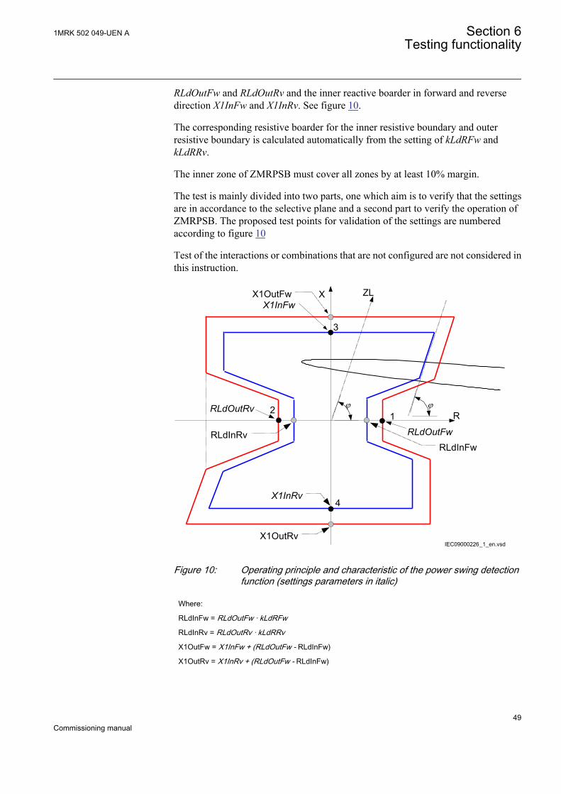
RLdOutFw and RLdOutRv and the inner reactive boarder in forward and reversedirection X1InFw and X1InRv. See figure 10.
The corresponding resistive boarder for the inner resistive boundary and outerresistive boundary is calculated automatically from the setting of kLdRFw andkLdRRv.
The inner zone of ZMRPSB must cover all zones by at least 10% margin.
The test is mainly divided into two parts, one which aim is to verify that the settingsare in accordance to the selective plane and a second part to verify the operation ofZMRPSB. The proposed test points for validation of the settings are numberedaccording to figure 10
Test of the interactions or combinations that are not configured are not considered inthis instruction.
X1OutRv
ZL
j jR
XX1OutFwX1InFw
1RLdOutFw
RLdInFw
RLdOutRv
RLdInRv
2
3
4X1InRv
IEC09000226_1_en.vsd
IEC09000226 V1 EN
Figure 10: Operating principle and characteristic of the power swing detectionfunction (settings parameters in italic)
Where:
RLdInFw = RLdOutFw · kLdRFw
RLdInRv = RLdOutRv · kLdRRv
X1OutFw = X1InFw + (RLdOutFw - RLdInFw)
X1OutRv = X1InRv + (RLdOutFw - RLdInFw)
1MRK 502 049-UEN A Section 6Testing functionality
49Commissioning manual
6.4.1.1 Verifying the settings
Preconditions
The following output signal shall be configured to binary output available: ZOUT,measured impedance within outer impedance boundary.
1. Keep the measured current as close as possible to its rated value or lower. Keepit constant during the test, but ensure that it is higher than the set minimumoperating current.
2. Ensure that the maximum continuous current to the IED does not exceed fourtimes its rated value, if the measurement of the operating characteristics runsunder constant voltage conditions.
3. Make the necessary connections and settings of the test equipment for test ofpoint 1 according to figure 10.
4. Decrease the measured three-phase impedance slowly and observe the operationvalue for the signal ZOUT.
5. Compare the operation value with the set value.6. Do the necessary change of the setting of the test equipment and repeat step 4 and
step 5 for point 2, 3 and 4 according to figure 10.
6.4.1.2 Testing the power swing detection function ZMRPSB
Preconditions
The following output signals shall be configured to binary outputs: ZOUT, measuredimpedance within outer impedance boundary, ZIN, measured impedance within innerimpedance boundary and START, power swing detection.
1. Slowly decrease the measured impedance in all three phases until the STARTsignal gets activated.
2. Increase the measured voltages to their rated values.3. Decrease instantaneously voltages in all three phases to the values, which are
approximately 20% lower than the voltage that gives the set value R1LIn at thepredefined test current.
4. The START signal must not appear.5. Increase the measured voltages to their rated values.
6.4.1.3 Testing the tR1 timer
Preconditions
• The input I0CHECK, residual current (3I0) detection used to inhibit the startoutput must be configured to the output signal STPE on the FDPSPDIS function.
• The input BLKI02, block inhibit of the start output for subsequent residualcurrent detection is connected to FALSE.
Section 6 1MRK 502 049-UEN ATesting functionality
50Commissioning manual
1. Program the test equipment for a single-phase to earth fault and energizeFDPSPDIS and check that the input BLOCK on the power swing detectionfunction ZMRPSB is activated.
2. Make a test sequence so that a single-phase to earth fault occurs after that thetrajectory of the impedance has passed the outer and inner boundary ofZMRPSB during power swing. Use the result from test of ZMRPSB above todetermine when the fault shall be applied. The earth-fault must be activatedbefore tR1 has elapsed.
3. Start the sequence and observe that the START signal will not be activated.
6.4.1.4 Testing the block input, interaction between FDPSPDIS and ZMRPSB
Precondition
The BLOCK input is configured and connected to STPE output on the FDPSPDISfunction.
1. Make a test sequence so that a single phase-to-earth-fault occurs after that thetrajectory of the impedance has passed the outer boundary but not the innerboundary of the power swing detection function ZMRPSB. Use the result fromtest of ZMRPSBabove to instance when the fault shall be applied.
2. Start the test sequence by continuously reducing the voltage and observe that theoutput signal ZOUT may come, but not START.If the input I0CHECK is configured (connected to output signal STPE onFDPSPDIS, the test of inhibit of ZMRPSB at earth-fault during power swing canbe done in the same way as for test of tR1.
6.4.1.5 Completing the test
Continue to test another function or end the testing by setting the parameter TestModeto Off under Main menu/Tests/IED test mode/TESTMODE:1. If another functionis tested, then set the parameter Blocked to No under Main menu/Tests/Function testmodes/Impedance/ZMRPSB(68)/ZMRPSB:1 for the function, or for eachindividual function in a chain, to be tested next. Remember to set the parameterBlocked to Yes, for each individual function that has been tested.
6.4.2 Underimpedance protection for generators and transformersZGCPDIS
Values of the logical signals for ZGCPDIS are available on the local HMI under Mainmenu/Tests/Function status/Impedance/ZGCPDIS(21G,Z<)/ZGCPDIS:1. TheSignal Monitoring in PCM600 shows the same signals that are available on the localHMI.
1MRK 502 049-UEN A Section 6Testing functionality
51Commissioning manual
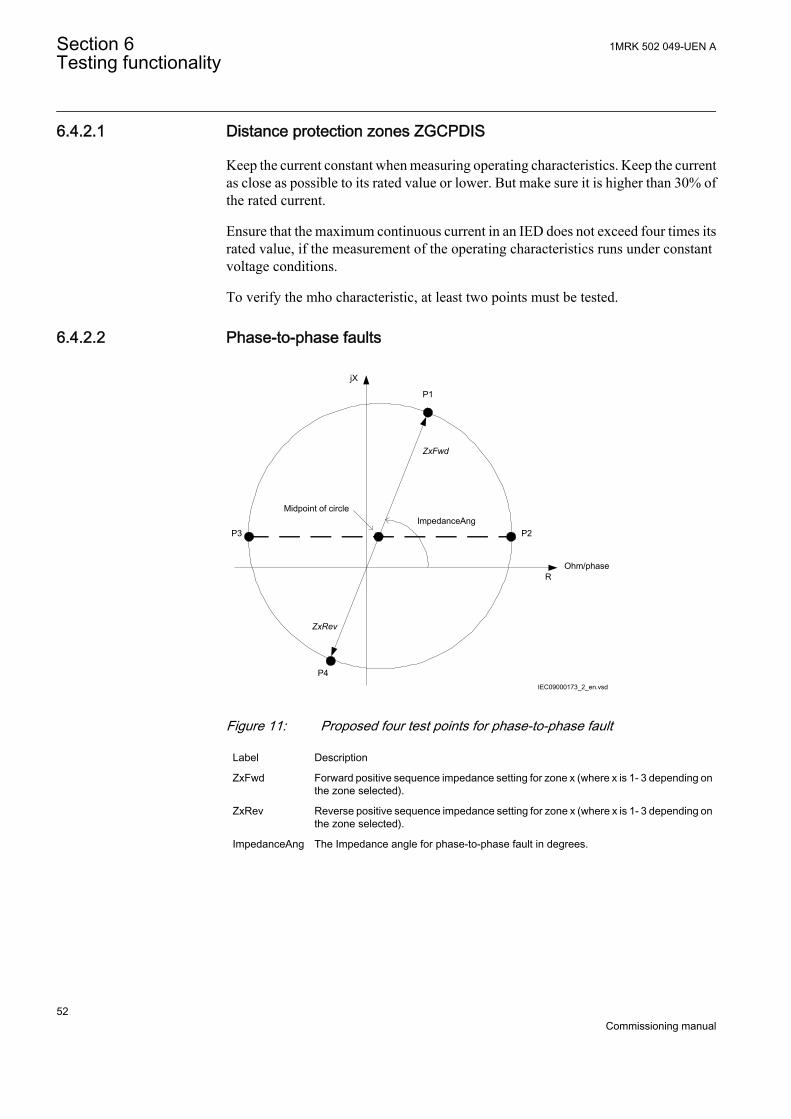
6.4.2.1 Distance protection zones ZGCPDIS
Keep the current constant when measuring operating characteristics. Keep the currentas close as possible to its rated value or lower. But make sure it is higher than 30% ofthe rated current.
Ensure that the maximum continuous current in an IED does not exceed four times itsrated value, if the measurement of the operating characteristics runs under constantvoltage conditions.
To verify the mho characteristic, at least two points must be tested.
6.4.2.2 Phase-to-phase faults
jX
ROhm/phase
ImpedanceAng
ZxFwd
ZxRev
P1
P2P3
P4
Midpoint of circle
IEC09000173_2_en.vsd
IEC09000173 V2 EN
Figure 11: Proposed four test points for phase-to-phase fault
Label Description
ZxFwd Forward positive sequence impedance setting for zone x (where x is 1- 3 depending onthe zone selected).
ZxRev Reverse positive sequence impedance setting for zone x (where x is 1- 3 depending onthe zone selected).
ImpedanceAng The Impedance angle for phase-to-phase fault in degrees.
Section 6 1MRK 502 049-UEN ATesting functionality
52Commissioning manual
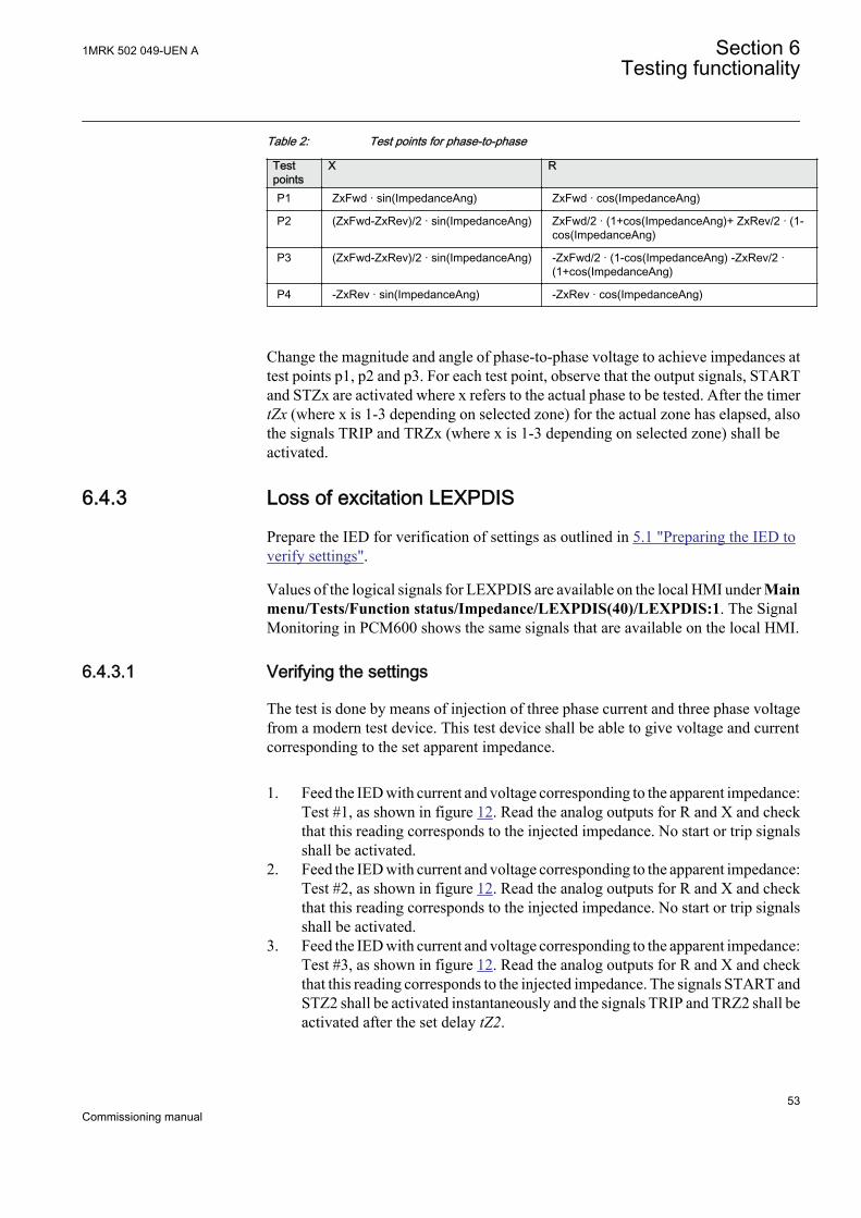
Table 2: Test points for phase-to-phase
Testpoints
X R
P1 ZxFwd · sin(ImpedanceAng) ZxFwd · cos(ImpedanceAng)
P2 (ZxFwd-ZxRev)/2 · sin(ImpedanceAng) ZxFwd/2 · (1+cos(ImpedanceAng)+ ZxRev/2 · (1-cos(ImpedanceAng)
P3 (ZxFwd-ZxRev)/2 · sin(ImpedanceAng) -ZxFwd/2 · (1-cos(ImpedanceAng) -ZxRev/2 ·(1+cos(ImpedanceAng)
P4 -ZxRev · sin(ImpedanceAng) -ZxRev · cos(ImpedanceAng)
Change the magnitude and angle of phase-to-phase voltage to achieve impedances attest points p1, p2 and p3. For each test point, observe that the output signals, STARTand STZx are activated where x refers to the actual phase to be tested. After the timertZx (where x is 1-3 depending on selected zone) for the actual zone has elapsed, alsothe signals TRIP and TRZx (where x is 1-3 depending on selected zone) shall beactivated.
6.4.3 Loss of excitation LEXPDIS
Prepare the IED for verification of settings as outlined in 5.1 "Preparing the IED toverify settings".
Values of the logical signals for LEXPDIS are available on the local HMI under Mainmenu/Tests/Function status/Impedance/LEXPDIS(40)/LEXPDIS:1. The SignalMonitoring in PCM600 shows the same signals that are available on the local HMI.
6.4.3.1 Verifying the settings
The test is done by means of injection of three phase current and three phase voltagefrom a modern test device. This test device shall be able to give voltage and currentcorresponding to the set apparent impedance.
1. Feed the IED with current and voltage corresponding to the apparent impedance:Test #1, as shown in figure 12. Read the analog outputs for R and X and checkthat this reading corresponds to the injected impedance. No start or trip signalsshall be activated.
2. Feed the IED with current and voltage corresponding to the apparent impedance:Test #2, as shown in figure 12. Read the analog outputs for R and X and checkthat this reading corresponds to the injected impedance. No start or trip signalsshall be activated.
3. Feed the IED with current and voltage corresponding to the apparent impedance:Test #3, as shown in figure 12. Read the analog outputs for R and X and checkthat this reading corresponds to the injected impedance. The signals START andSTZ2 shall be activated instantaneously and the signals TRIP and TRZ2 shall beactivated after the set delay tZ2.
1MRK 502 049-UEN A Section 6Testing functionality
53Commissioning manual

4. Switch the current infeed injection off. The function shall reset. Turn the currenton with the values corresponding to Test #3 and measure the time to activationof signal TRZ2. This time shall be compared to tZ2.
5. Feed the IED with current and voltage corresponding to the apparent impedance:Test #4, as shown in figure 12. Read the analog outputs for R and X and checkthat this reading corresponds to the injected impedance. The signals START,STZ2 and STZ1 shall be activated instantaneously and the signals TRIP, TRZ2and TRZ1 shall be activated after the different set time delays.
6. Switch the current infeed injection off. The function shall reset. Turn the currenton with the values corresponding to Test #4 and measure the time to activationof signal TRZ1. This time shall be compared to tZ1.
IEC06000513-2-en.vsd
R
X
Underexcitation Protection Restrain area
Z1, Fast zone
Z2, Slow zone
Test #1Test #2
Test #3
Test #4
IEC06000513 V2 EN
Figure 12: Testing current and voltage corresponding to the apparentimpedance
6.4.3.2 Completing the test
Continue to test another function or end the testing by setting the parameter TestModeto Off under Main menu/Tests/IED test mode/TESTMODE:1. If another functionis tested, then set the parameter Blocked to No under Main menu/Tests/Function testmodes/Impedance/LEXPDIS(40)/LEXPDIS:1 for the function, or for eachindividual function in a chain, to be tested next. Remember to set the parameterBlocked to Yes, for each individual function that has been tested.
Section 6 1MRK 502 049-UEN ATesting functionality
54Commissioning manual
6.4.4 Out-of-step OOSPPAM
Prepare the IED for verification of settings as outlined in 5.1 "Preparing the IED toverify settings".
Values of the logical signals for OOSPPAM are available on the local HMI underMain menu/Tests/Function status/Impedance/OOSPPAM(78)/OOSPPAM:1.The Signal Monitoring in PCM600 shows the same signals that are available on thelocal HMI.
6.4.4.1 Verifying the settings
The commissioning procedure requires only one calculation and it must be done whenall the settings have already been determined. Suppose that the voltages, the currentsand the impedances ForwardR, ForwardX, ReverseR and ReverseX are equal to thosein the example as described in the "Setting guidelines" section for the Out-of-stepprotection function in the REG650 Application manual.
1. Calculate the magnitude of a fundamental frequency current I that results in themeasured reactance ForwardX, as shown in point A in Figure 13.
I A U ForwardX
I A kV Ohm
I A
gen[ ] =
[ ] =
[ ] =
/ /
. / / .
3
13 8 3 0 565
14107
IECEQUATION2321 V1 EN (Equation 1)2. Three symmetrical fundamental frequency phase voltages must be fed to IED,
with magnitudes proportional to Ugen / √(3), that is, taking into the account theactual PT ratio in the IED. If three symmetrical fundamental frequency currents,proportional to I = 14107 A, that is, taking into the account the CT ratio, are fedto the IED, and they all lag their phase voltages by 90 electrical degrees,OOSPPAM function must measure a reactance equal to ForwardX, that is, 59.33percent of Zbase, corresponding to 0.565 Ohm. This reactance is constant andstationary, as shown in point A in Figure 13. The voltages and the currents mustbe calculated to perform the injection by a test set.Voltages (instantaneous values) of the fundamental frequency, that is, 50 Hz or60 Hz, must be as follows. Example for fundamental frequency 50 Hz:
u U tL phase1 2 2 50 0= ⋅ ⋅ ⋅ ⋅ ⋅( )sin .π
IECEQUATION2328 V1 EN (Equation 2)
u U tL phase2 2 2 50 0 2 3= ⋅ ⋅ ⋅ ⋅ ⋅ − ⋅( )sin . /π π
IECEQUATION2329 V1 EN (Equation 3)
u U tL phase3 2 2 50 0 4 3= ⋅ ⋅ ⋅ ⋅ − ⋅( )sin . /π π
IECEQUATION2330 V1 EN (Equation 4)
Where Uphase = Ugen / √(3) = 13800 V / √(3) = 7967.4 Volts. The actual PT ratiomust be applied to this primary value of the phase voltage, so that the actual valueof the secondary input voltage applied to IED can be calculated.
1MRK 502 049-UEN A Section 6Testing functionality
55Commissioning manual
The three symmetrical currents of the fundamental frequency, 50 Hz (or 60 Hz),must be as follows:
i I tL1 2 2 50 0 2= ⋅ ⋅ ⋅ ⋅ ⋅ −( )sin . /π π
IECEQUATION2325 V1 EN (Equation 5)
i I tL2 2 2 50 0 2 2 3= ⋅ ⋅ ⋅ ⋅ ⋅ − − ⋅( )sin . / /π π π
IECEQUATION2326 V1 EN (Equation 6)
i I tL3 2 2 50 0 2 4 3= ⋅ ⋅ ⋅ ⋅ ⋅ − − ⋅( )sin . / /π π π
IECEQUATION2327 V1 EN (Equation 7)
Where I = Ugen / √(3) / ForwardX = 14107 A. The actual CT ratio must be appliedto this primary current so that correct value of the secondary injected current canbe calculated.Expected result: The function must measure a reactance X = ForwardX = 59.33percent of Zbase, which corresponds to 0.565 Ohm. The TRIP signal must remainFALSE (0).
3. In the last step of the commissioning procedure, apart from the fundamentalfrequency current described above, another current component must be injected,with a frequency equal to the nominal frequency ± 1.000 Hz. For nominalfrequency 50 Hz, first 49.000 Hz and then 51.000 Hz. The magnitude of thisadditional current component must be 0.9 times current I. If the symmetricaladditional current component in all three phases has 49.000 Hz, the trajectory ofthe complex impedance has to be exactly as illustrated in Figure 13. The compleximpedance Z(R, X) travels from the right side towards the left side, as shown inFigure 13. The Boolean output signal GENMODE must be set to TRUE (1) asshown in Figure 14. If the X-line is set in a way, so that the zone 2 begins on thepower transformer HV-side terminals, as described in Figure 13, then all the poleslips occur in zone 2, and this can be observed as the Boolean output TRIPZ2,which must be periodically (with 1 Hz) set to TRUE (1), and then reset to FALSE(0). The output trip must be set to TRUE (1) and persist at that value under thistest. If the additional component of the current is 51.000 Hz, the compleximpedance Z(R, X) travels from the left side towards the right side and theBoolean output signal MOTMODE has to be set to TRUE (1). The rest of thesignals must be as under the 49 Hz test.If a test set (for example, Omicron) is to be programmed for the abovecommissioning test, then the currents must be as follows (while the voltagesremain as in step 2):Currents (instantaneous values) with two components, of which one has thefundamental frequency, that is, 50 Hz or 60 Hz, must be as follows. Example forfundamental frequency 50 Hz:
i I t I tL1 2 2 50 0 2 2 0 9 2 49 0 2= ⋅ ⋅ ⋅ −( ) + ⋅ ⋅ ⋅ ⋅ ⋅ −( )sin . / . sin . /π π π π
IECEQUATION2322 V1 EN (Equation 8)
i I t I tL2 2 2 50 0 2 2 3 2 0 9 2 49 0 2= ⋅ ⋅ ⋅ ⋅ − − ⋅( ) + ⋅ ⋅ ⋅ ⋅ ⋅ − −sin . / / . sin . /π π π π π 22 3⋅( )π /
IECEQUATION2323 V1 EN (Equation 9)
i I t I tL3 2 2 50 0 2 4 3 2 0 9 2 49 0 2= ⋅ ⋅ ⋅ ⋅ − − ⋅( ) + ⋅ ⋅ ⋅ ⋅ ⋅ − −sin . / / . sin . /π π π π π 44 3⋅( )π /
IECEQUATION2324 V1 EN (Equation 10)
Section 6 1MRK 502 049-UEN ATesting functionality
56Commissioning manual
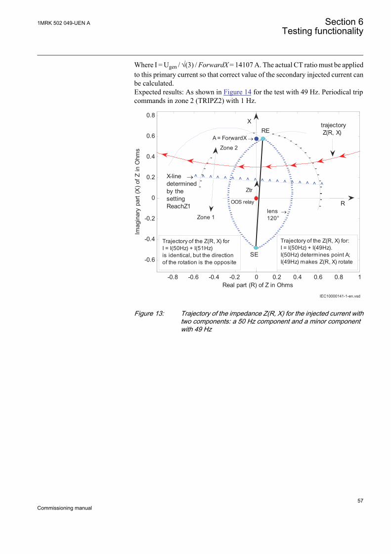
Where I = Ugen / √(3) / ForwardX = 14107 A. The actual CT ratio must be appliedto this primary current so that correct value of the secondary injected current canbe calculated.Expected results: As shown in Figure 14 for the test with 49 Hz. Periodical tripcommands in zone 2 (TRIPZ2) with 1 Hz.
IEC10000141-1-en.vsd
-0.8 -0.6 -0.4 -0.2 0 0.2 0.4 0.6 0.8 1
-0.6
-0.4
-0.2
0
0.2
0.4
0.6
0.8
-------------------------------------------------------------------
------
-----
------------------------------
------
------
Real part (R) of Z in Ohms
Imag
inar
y pa
rt (X
) of Z
in O
hms
^ ^ ^ ^ ^ ^ ^ ^ ^ ^ ^ ^ ^ ^ ^ ^ ^ ^---
--
--
----------------
--
--
---- -
--
--
--
--
--------------
--
--
----
trajectory Z(R, X)
R
Trajectory of the Z(R, X) for:I = I(50Hz) + I(49Hz).I(50Hz) determines point A;I(49Hz) makes Z(R, X) rotate
SE
Zone 1
Trajectory of the Z(R, X) forI = I(50Hz) + I(51Hz)is identical, but the directionof the rotation is the opposite
OOS relay
Ztr
lens →120°
X-line →determinedby the settingReachZ1
REA = ForwardX →
Zone 2
Zone 1
X
IEC10000141 V1 EN
Figure 13: Trajectory of the impedance Z(R, X) for the injected current withtwo components: a 50 Hz component and a minor componentwith 49 Hz
1MRK 502 049-UEN A Section 6Testing functionality
57Commissioning manual

IEC10000142-1-en.vsd
012
COMMON TRIP COMMAND (trip)
-101
TRIPZ1 (tripZone1)
012
TRIPZ2 (tripZone2)
012
START (start)
012
GENMODE (generatorMode)
0 0.5 1 1.5 2 2.5 3 3.5 4 4.5 5-101
time in seconds →
MOTMODE (motorMode)
IEC10000142 V1 EN
Figure 14: Boolean output signals for the injected current with twocomponents: a 50 Hz current component and a component with49 Hz
6.4.5 Load encroachment LEPDIS
Prepare the IED for verification of settings as outlined in 5.1 "Preparing the IED toverify settings".
Values of the logical signals for LEPDIS are available on the local HMI under Mainmenu/Tests/Function status/Impedance/LEPDIS/LEPDIS:1. The SignalMonitoring in PCM600 shows the same signals that are available on the local HMI.
Load encroachment operates on the same measuring principles as the impedancemeasuring zones. Thus, it is necessary to follow the same principles as for distanceprotection when performing the secondary injection tests.
Measure operating characteristics during constant current conditions. Keep themeasured current as close as possible to the rated value of its associated inputtransformer or lower. Ensure, however, that it is higher than 30% of the rated current.
Section 6 1MRK 502 049-UEN ATesting functionality
58Commissioning manual

Ensure that the maximum continuous current of an IED does not exceed four times itsrated value, if the measurement of the operating characteristics runs under constantvoltage conditions.
6.4.5.1 Measuring the operate limit of set values
The load encroachment function has no outputs of its own. It can onlybe checked together with the impedance function.
1. Supply the IED with healthy conditions for at least two seconds.2. Apply the fault condition and slowly decrease the measured impedance to find
the operate value for of the phase-to-earth and phase-to-phase loops.
6.4.5.2 Completing the test
Continue to test another function or end the testing by setting the parameter TestModeto Off under Main menu/Tests/IED test mode/TESTMODE:1. If another functionis tested, then set the parameter Blocked to No under Main menu/Tests/Function testmodes/Impedance/LEPDIS/LEPDIS:1 for the function, or for each individualfunction in a chain, to be tested next. Remember to set the parameter Blocked to Yes,for each individual function that has been tested.
6.5 Testing current protection functions
6.5.1 Four step phase overcurrent protection 3-phase outputOC4PTOC
Prepare the IED for verification of settings as outlined in 5.1 "Preparing the IED toverify settings".
Values of the logical signals for OC4PTOC are available on the local HMI underMain menu/Tests/Function status/Current/OC4PTOC(51_67,4I>)/OC4PTOC:1. The Signal Monitoring in PCM600 shows the same signals that are available on thelocal HMI.
6.5.1.1 Verifying the settings
1. Connect the test set for current injection to the appropriate IED phases.If there is any configuration logic that is used to enable or block any of the fouravailable overcurrent steps, make sure that the step under test is enabled (forexample, end fault protection).
1MRK 502 049-UEN A Section 6Testing functionality
59Commissioning manual
Connect the symmetrical three-phase injection current into phases L1, L2 andL3.
2. Connect the test set for the appropriate three-phase voltage injection to the IEDphases L1, L2 and L3. The protection shall be fed with a symmetrical three-phase voltage.
3. Set the injected polarizing voltage slightly larger than the set minimumpolarizing voltage (default is 5% of UBase) and set the injection current to lagthe appropriate voltage by an angle of 55° if forward directional function isselected.If 1 out of 3 currents for operation is chosen: The voltage angle of phase L1 is thereference.If reverse directional function is selected, set the injection current to lag thepolarizing voltage by an angle equal to 235° (equal to 55° + 180°).
4. Increase the injected current and note the operate value of the tested step of thefunction.
5. Decrease the current slowly and note the reset value.6. If the test has been performed by injection of current in phase L1, repeat the test,
injecting current into phases L2 and L3 with polarizing voltage connected tophases L2, respectively L3 (1 out of 3 currents for operation).
7. If the test has been performed by injection of current in phases L1 – L2, repeatthe test, injecting current into phases L2 – L3 and L3 – L1 with the appropriatephase angle of injected currents.
8. Block higher set stages when testing lower set stages by following the proceduredescribed below.
9. Connect a trip output contact to a timer.10. Set the injected current to 200% of the operate level of the tested stage, switch
on the current and check the time delay.For inverse time curves, check the operate time at a current equal to 110% of theoperate current for txMin.
11. Check that all trip and start contacts operate according to the configuration(signal matrixes)
12. Reverse the direction of the injected current and check that the protection doesnot operate.
13. Repeat the above described tests for the higher set stages.14. Finally check that start and trip information is stored in the event menu.
Verification of the non-directional phase overcurrent function isdone as instructed above, without applying any polarizingvoltage.
6.5.1.2 Completing the test
Continue to test another function or end the testing by setting the parameter TestModeto Off under Main menu/Tests/IED test mode/TESTMODE:1. If another functionis tested, then set the parameter Blocked to No under Main menu/Tests/Function testmodes/Current/OC4PTOC(51_67,4I>)/OC4PTOC:1 for the function, or for each
Section 6 1MRK 502 049-UEN ATesting functionality
60Commissioning manual
individual function in a chain, to be tested next. Remember to set the parameterBlocked to Yes, for each individual function that has been tested.
6.5.2 Four step residual overcurrent protection, zero or negativesequence direction EF4PTOC
Prepare the IED for verification of settings as outlined in 5.1 "Preparing the IED toverify settings".
Values of the logical signals for EF4PTOC are available on the local HMI under Mainmenu/Tests/Function status/Current/EF4PTOC(51N67N,4IN>)/EF4PTOC:X.The Signal Monitoring in PCM600 shows the same signals that are available on thelocal HMI.
6.5.2.1 Four step directional residual overcurrent protection
1. Connect the test set for single current injection to the appropriate IED terminals.Connect the injection current and voltage to terminals L1 and neutral.
2. Set the injected polarizing voltage slightly larger than the set minimumpolarizing voltage (default 1% of Ur) and set the injection current to lag thevoltage by an angle equal to the set reference characteristic angle (AngleRCA),if the forward directional function is selected.If reverse directional function is selected, set the injection current to lag thepolarizing voltage by an angle equal to RCA+ 180°.
3. Increase the injected current and note the value at which the studied step of thefunction operates.
4. Decrease the current slowly and note the reset value.5. If the test has been performed by injection of current in phase L1, repeat the test,
injecting current into terminals L2 and L3 with a polarizing voltage connected toterminals L2, respectively L3.
6. Block lower set steps when testing higher set steps according to the instructionsthat follow.
7. Connect a trip output contact to a timer.8. Set the injected current to 200% of the operate level of the tested step, switch on
the current and check the time delay.For inverse time curves, check the operate time at a current equal to 110% of theoperate current for txMin.
9. Check that all trip and start contacts operate according to the configuration(signal matrixes)
10. Reverse the direction of the injected current and check that the step does notoperate.
11. Check that the protection does not operate when the polarizing voltage is zero.12. Repeat the above described tests for the higher set steps.13. Finally, check that start and trip information is stored in the event menu.
1MRK 502 049-UEN A Section 6Testing functionality
61Commissioning manual
6.5.2.2 Four step non-directional residual overcurrent protection
1. Do as described in "Four step directional residual overcurrent protection", butwithout applying any polarizing voltage.
6.5.2.3 Completing the test
Continue to test another function or end the testing by setting the parameter TestModeto Off under Main menu/Tests/IED test mode/TESTMODE:1. If another functionis tested, then set the parameter Blocked to No under Main menu/Tests/Function testmodes/Current/EF4PTOC(51N67N,4IN>)/EF4PTOC:X for the function, or foreach individual function in a chain, to be tested next. Remember to set the parameterBlocked to Yes, for each individual function that has been tested.
6.5.3 Sensitive directional residual overcurrent and powerprotection SDEPSDE
Prepare the IED for verification of settings as outlined in 5.1 "Preparing the IED toverify settings".
Values of the logical signals for SDEPSDE are available on the local HMI under Mainmenu/Tests/Function status/Current/SDEPSDE(67N,IN<->)/SDEPSDE:1. TheSignal Monitoring in PCM600 shows the same signals that are available on the localHMI.
6.5.3.1 Measuring the operate and time limit for set values
Operation mode 3I0 · cosφProcedure
1. Set the polarizing voltage to 1.2 · UNRel> and the phase angle between voltageand current to the set characteristic angle (RCADir), the current lagging thevoltage.Take setting RCAComp into consideration if not equal to 0.
2. Measure that the operate current of the set directional element is equal to theINcosPhi> setting.The I Dir (I0 cos(Angle)) function activates the START and STDIRIN output.
3. Measure with angles j = RCADir +/- 45° that the measuring element operateswhen I0 cos (RCADir - j) = I0cos(+/-45) = INcosPhi>.
4. Compare the result with the set value.Take the set characteristic into consideration, see figure 15 and figure 16.
5. Measure the operate time of the timer by injecting a current two times the setINcosPhi> value and the polarizing voltage 1.2 · UNRel>.
Section 6 1MRK 502 049-UEN ATesting functionality
62Commissioning manual
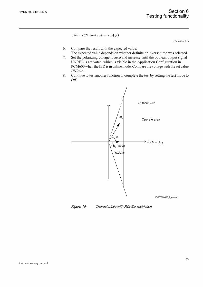
( )0/ 3 costestTinv kSN Sref I j= × ×
IECEQUATION2402 V1 EN (Equation 11)
6. Compare the result with the expected value.The expected value depends on whether definite or inverse time was selected.
7. Set the polarizing voltage to zero and increase until the boolean output signalUNREL is activated, which is visible in the Application Configuration inPCM600 when the IED is in online mode. Compare the voltage with the set valueUNRel>.
8. Continue to test another function or complete the test by setting the test mode toOff.
Operate area
ROADir
IEC06000650_2_en.vsd
= o0RCADir
03I
j
03 × jI cos- =03 refU U
IEC06000650 V2 EN
Figure 15: Characteristic with ROADir restriction
1MRK 502 049-UEN A Section 6Testing functionality
63Commissioning manual

-3U0=Uref
Operate area
Instrumenttransformerangle error
3I0 (prim) 3I0 (to prot)
a
Characteristic afterangle compensation
RCAcomp
en06000651.vsd
RCADir = 0º
IEC06000651 V2 EN
Figure 16: Explanation of RCAcomp
Operation mode 3I0 · 3U0 · cosφ
1. Set the polarizing voltage to 1.2 · UNRel> and the phase angle between voltageand current to the set characteristic angle (RCADir), the current lagging thevoltage.
2. Measure that the operate power is equal to the SN> setting for the set directionalelement.Note that for operation, both the injected current and voltage must be greaterthan the set values INRel> and UNRel> respectively.The function activates the START and STDIRIN outputs.
3. Measure with angles j = RCADir +/- 45° that the measuring element operateswhen 3I0 · 3U0 · cos (RCADir - j) = 3I0 · 3U0 · cos(+/-45) = SN>.
4. Compare the result with the set value. Take the set characteristic intoconsideration, see figure 15 and figure 16.
5. Measure the operate time of the timer by injecting 1.2 · UNRel> and a current toget two times the set SN> operate value.
Section 6 1MRK 502 049-UEN ATesting functionality
64Commissioning manual

( )0 0/ 3 3 costest testTinv kSN Sref I U j= × × ×
IECEQUATION2403 V1 EN (Equation 12)
6. Compare the result with the expected value.The expected value depends on whether definite or inverse time was selected.
7. Continue to test another function or complete the test by setting the test mode toOff.
Operation mode 3I0 and φ
1. Set the polarizing voltage to 1.2 · UNRel> and the phase angle between voltageand current to the set characteristic angle (RCADir), the current lagging thevoltage.
2. Measure that the operate power is equal to the INDir> setting for the setdirectional element.
Note that for operation, both the injected current and voltagemust be greater than the set values INRel> and UNRel>respectively.
The function activates the START and STDIRIN output.3. Measure with angles j around RCADir +/- ROADir.4. Compare the result with the set values, refer to figure 17 for example
characteristic.5. Measure the operate time of the timer by injecting a current to get two times the
set SN_> operate value.
( )0 0/ 3 3 costest testTinv kSN Sref I U j= × × ×
IECEQUATION2403 V1 EN (Equation 13)
6. Compare the result with the expected value.The expected value depends on whether definite or inverse time was selected.
7. Continue to test another function or complete the test by setting the test mode toOff.
1MRK 502 049-UEN A Section 6Testing functionality
65Commissioning manual

-3U0
Operate area
3I0
RCADir = 0º
ROADir = 80º
IEC06000652-3-en.vsdIEC06000652 V3 EN
Figure 17: Example characteristic
Non-directional earth fault current protectionProcedure
1. Measure that the operate current is equal to the INNonDir> setting.The function activates the START and STDIRIN output.
2. Measure the operate time of the timer by injecting a current of 200% of theoperate value.
3. Compare the result with the expected value.The expected value depends on whether definite time tINNonDir or inverse timewas selected.
4. Continue to test another function or complete the test by setting the test mode toOff.
Residual overvoltage release and protectionProcedure
1. Measure that the operate voltage is equal to the UN> setting.The function activates the START and STUN signals.
2. Measure the operate time by injecting a voltage 1.2 timers set UN> operatevalue.
3. Compare the result with the set tUN operate value.4. Inject a voltage 0.8 · UNRel> and a current high enough to operate the
directional function at the chosen angle.5. Increase the voltage until the directional function is released.6. Compare the measured value with the set UNRel> operate value.
Section 6 1MRK 502 049-UEN ATesting functionality
66Commissioning manual

6.5.3.2 Completing the test
Continue to test another function or end the testing by setting the parameter TestModeto Off under Main menu/Tests/IED test mode/TESTMODE:1. If another functionis tested, then set the parameter Blocked to No under Main menu/Tests/Function testmodes/Current/SDEPSDE(67N,IN<->)/SDEPSDE:1 for the function, or for eachindividual function in a chain, to be tested next. Remember to set the parameterBlocked to Yes, for each individual function that has been tested.
6.5.4 Thermal overload protection, two time constants TRPTTR
Prepare the IED for verification of settings as outlined in 5.1 "Preparing the IED toverify settings".
Values of the logical signals for TRPTTR are available on the local HMI under Mainmenu/Tests/Function status/Current/TRPTTR(49,T>)/TRPTTR:X. The SignalMonitoring in PCM600 shows the same signals that are available on the local HMI.
6.5.4.1 Checking operate and reset values
1. Connect symmetrical three-phase currents to the appropriate current terminalsof the IED.
2. Set the Time constant 1 (Tau1) and Time Constant 2 (Tau2) temporarily to 1minute.
3. Set the three-phase injection currents slightly lower than the set operate value ofstage IBase1, increase the current in phase L1 until stage IBase1 operates andnote the operate value.
Observe the maximum permitted overloading of the currentcircuits in the IED.
4. Decrease the current slowly and note the reset value.
Check, in the same way, the operate and reset values of IBase1 for phases L2 andL3.
5. Activate the cooling input signal, thus switching to base current IBase2.6. Check the operate and reset values (for all three phases) for IBase2 in the same
way as described above for stage IBase1.7. Deactivate the input signal for stage IBase2.8. Set the time constant for IBase1 in accordance with the setting plan.9. Set the injection current for phase L1 to 1.50 · IBase1.10. Connect a trip output contact to the timer and monitor the output of contacts
ALARM1 and ALARM2 to digital inputs in test equipment.Read the heat content in the thermal protection from the local HMI and wait untilthe content is zero.
1MRK 502 049-UEN A Section 6Testing functionality
67Commissioning manual

11. Switch on the injection current and check that ALARM1 and ALARM2 contactsoperate at the set percentage level and that the operate time for tripping is inaccordance with the set Time Constant 1 (Tau1).With setting Itr = 101%IBase1 and injection current 1.50 · IBase1, the trip timefrom zero content in the memory shall be 0.60 · Time Constant 1 (Tau1).
12. Check that all trip and alarm contacts operate according to the configurationlogic.
13. Switch off the injection current and check from the service menu readings ofthermal status and LOCKOUT that the lockout resets at the set percentage ofheat content.
14. Activate the cooling input signal to switch over to base current IBase2.Wait 5 minutes to empty the thermal memory and set Time Constant 2 (Tau2) inaccordance with the setting plan.
15. Test with injection current 1.50 · IBase2 the thermal alarm level, the operatetime for tripping and the lockout reset in the same way as described for stageIBase1.
16. Finally check that start and trip information is stored in the event menu.
6.5.4.2 Completing the test
Continue to test another function or end the testing by setting the parameter TestModeto Off under Main menu/Tests/IED test mode/TESTMODE:1. If another functionis tested, then set the parameter Blocked to No under Main menu/Tests/Function testmodes/Current/TRPTTR(49,T>)/TRPTTR:X for the function, or for eachindividual function in a chain, to be tested next. Remember to set the parameterBlocked to Yes, for each individual function that has been tested.
6.5.5 Breaker failure protection, phase segregated activation andoutput CCRBRF
Prepare the IED for verification of settings as outlined in 5.1 "Preparing the IED toverify settings".
Values of the logical signals for CCRBRF are available on the local HMI under Mainmenu/Tests/Function status/Current/CCRBRF(50BF)/CCRBRF:1. The SignalMonitoring in PCM600 shows the same signals that are available on the local HMI.
The Breaker failure protection, 3-phase activation and output function CCRBRFshould normally be tested in conjunction with some other function that provides a startsignal. An external START signal can also be used.
To verify the settings in the most common back-up trip mode 1 out of 3, it is sufficientto test phase-to-earth faults.
At mode 2 out of 4 the phase current setting, IP> can be checked by single-phaseinjection where the return current is connected to the summated current input. Thevalue of residual (earth fault) current IN set lower than IP> is easiest checked in back-up trip mode 1 out of 4.
Section 6 1MRK 502 049-UEN ATesting functionality
68Commissioning manual

6.5.5.1 Checking the phase current operate value, IP>
Check the current level IP> where setting FunctionMode=Current and settingBuTripMode=1 out of 3 or 2 out of 4 as set under Main menu/Settings/IED Settings/Current/CCRBRF(50BF)/CCRBRF:1.
1. Apply the fault condition, including START of CCRBRF, with a current belowset IP>.
2. Repeat the fault condition and increase the current in steps until a trip occurs.3. Compare the result with the set IP>.4. Disconnect AC and START input signals.
Note! If NoI>check or Retrip off is set, only back-up trip can beused to check set IP>.
6.5.5.2 Checking the residual (earth fault) current operate value IN> set belowIP>
Check the low set IN> current where setting FunctionMode = Current and settingBuTripMode = 1 out of 4 as set under Main menu/Settings/IED Settings/Current/CCRBRF(50BF)/CCRBRF:1.
1. Apply the fault condition, including START of CCRBRF, with a current justbelow set IN>Pickup_N.
2. Repeat the fault condition and increase the current in steps until trip appears.3. Compare the result with the set IN>.4. Disconnect AC and START input signals.
6.5.5.3 Checking the re-trip and back-up times
The check of the set times can be made in connection with the check of operate valuesabove.
Choose the applicable function and trip mode, such as FunctionMode = Current andsetting RetripMode = No CBPos. Check as set under Main menu/Settings/IEDSettings/Current/CCRBRF(50BF)/CCRBRF:1.
1. Apply the fault condition, including start of CCRBRF, well above the set currentvalue. Measure time from START of CCRBRF.
2. Check the re-trip t1 and back-up trip times t2.3. Disconnect AC and START input signals.
1MRK 502 049-UEN A Section 6Testing functionality
69Commissioning manual

6.5.5.4 Verifying the re-trip mode
Choose the mode below, which corresponds to the actual case.
In the cases below it is assumed that FunctionMode = Current as set under Mainmenu/Settings/IED Settings/Current/CCRBRF(50BF)/CCRBRF:1.
Checking the case without re-trip, RetripMode = Retrip Off
1. Set RetripMode = Retrip Off.2. Apply the fault condition, including start of CCRBRF, well above the set current
value.3. Verify that no re-trip, but back-up trip is achieved after set time.4. Disconnect AC and START input signals.
Checking the re-trip with current check, RetripMode = CB Pos Check
1. Set RetripMode = CB Pos Check.2. Apply the fault condition, including start of CCRBRF, well above the set current
value.3. Verify that re-trip is achieved after set time t1 and back-up trip after time t24. Apply the fault condition, including start of CCRBRF, with current below set
current value.5. Verify that no re-trip, and no back-up trip is obtained.6. Disconnect AC and START input signals.
Checking re-trip without current check, RetripMode = No CBPos Check
1. Set RetripMode = No CBPos Check.2. Apply the fault condition, including start of CCRBRF, without any current.3. Verify that re-trip is achieved after set time t1, and back-up trip after time t2.4. Apply the fault condition, including start of CCRBRF, with current below set
current value.5. Verify that re-trip is achieved after set time t1, but no back-up trip is obtained.6. Disconnect AC and START input signals.
6.5.5.5 Verifying the back-up trip mode
In the cases below it is assumed that FunctionMode = Current is selected.
Checking that back-up tripping is not achieved at normal CB trippingUse the actual tripping modes. The case below applies to re-trip with current check.
Section 6 1MRK 502 049-UEN ATesting functionality
70Commissioning manual

1. Apply the fault condition, including start of CCRBRF, with phase current wellabove set value IP.
2. Interrupt the current, with a margin before back-up trip time, t2. It may be madeat issue of re-trip command.
3. Check that re-trip is achieved, if selected, but no back-up trip is obtained.4. Disconnect AC and START input signals.
The normal mode BuTripMode = 1 out of 3 should have been verified in the testsabove. In applicable cases the modes 1 out of 4 and 2 out of 4 can be checked. Choosethe mode below, which corresponds to the actual case.
Checking the case BuTripMode = 1 out of 4It is assumed that the earth-fault current setting IN> is below phase current settingIP>.
1. Set BuTripMode = 1 out of 4.2. Apply the fault condition, including start of CCRBRF, with one-phase current
below set IP> but above IN>. The residual earth-fault should then be above setIN>.
3. Verify that back-up trip is achieved after set time. If selected, re-trip should alsoappear.
4. Disconnect AC and START input signals.
Checking the case BuTripMode = 2 out of 4The earth-fault current setting IN> may be equal to or below phase-current settingIP>.
1. Set BuTripMode = 2 out of 4.2. Apply the fault condition, including start of CCRBRF, with one-phase current
above set IP> and residual (earth fault) above set IN>.3. Verify that back-up trip is achieved after set time. If selected, re-trip should also
appear.4. Apply the fault condition, including start of CCRBRF, with at least one-phase
current below set IP> and residual (earth fault) above set IN>. The current maybe arranged by feeding three- (or two-) phase currents with equal phase angle(I0-component) below IP>, but of such value that the residual (earth fault)current (3I0) will be above set value IN>.
5. Verify that back-up trip is not achieved.6. Disconnect AC and START input signals.
6.5.5.6 Verifying the case RetripMode = Contact
It is assumed that re-trip without current check is selected, RetripMode = Contact.
1MRK 502 049-UEN A Section 6Testing functionality
71Commissioning manual

1. Set FunctionMode = Contact2. Apply input signal for CB closed to input CBCLDL1, CBCLD2 or CBCDL3.3. Apply input signal, for start of CCRBRF.4. Verify that phase selection re-trip and back-up trip are achieved after set times.5. Disconnect the start signal. Keep the CB closed signal.6. Apply input signal, for start of CCRBRF.7. Arrange disconnection of CB closed signal well before set back-up trip time t2.8. Verify that back-up trip is not achieved.9. Disconnect injected AC and START input signals.
6.5.5.7 Verifying the function mode Current&Contact
To be made only when FunctionMode = Current&Contact is selected.
Checking the case with fault current above set value IP>The operation shall be as in FunctionMode = Current.
1. Set FunctionMode = Current&Contact.2. Leave the inputs for CB close inactivated. These signals should not influence.3. Apply the fault condition, including start of CCRBRF, with current above the set
IP> value.4. Check that the re-trip, if selected, and back-up trip commands are achieved.5. Disconnect injected AC and START input signals.
Checking the case with fault current below set value I>BlkContThe case shall simulate a case where the fault current is very low and operation willdepend on CB position signal from CB auxiliary contact. It is suggested that re-tripwithout current check is used, setting RetripMode = No CBPos Check.
1. Set FunctionMode = Current&Contact.2. Apply input signal for CB closed to relevant input or inputs CBCLDL1 (2 or 3)3. Apply the fault condition with input signal(s) for start of CCRBRF. The value of
current should be below the set value I>BlkCont4. Verify that phase selection re-trip (if selected) and back-up trip are achieved
after set times. Failure to trip is simulated by keeping the signal(s) CB closedactivated.
5. Disconnect the AC and the START signal(s). Keep the CB closed signal(s).6. Apply the fault and the start again. The value of current should be below the set
value I>BlkCont.7. Arrange disconnection of BC closed signal(s) well before set back-up trip time
t2. It simulates a correct CB tripping.8. Verify that back-up trip is not achieved. Re-trip can appear for example, due to
selection “Re-trip without current check”.9. Disconnect injected AC and START input signals.
Section 6 1MRK 502 049-UEN ATesting functionality
72Commissioning manual

6.5.5.8 Completing the test
Continue to test another function or end the testing by setting the parameter TestModeto Off under Main menu/Tests/IED test mode/TESTMODE:1. If another functionis tested, then set the parameter Blocked to No under Main menu/Tests/Function testmodes/Current/CCRBRF(50BF)/CCRBRF:X for the function, or for eachindividual function in a chain, to be tested next. Remember to set the parameterBlocked to Yes, for each individual function that has been tested.
6.5.6 Pole discordance protection CCRPLD
Prepare the IED for verification of settings as outlined in 5.1 "Preparing the IED toverify settings".
Values of the logical signals for CCRPLD are available on the local HMI under Mainmenu/Tests/Function status/Current/CCRPLD(52PD)/CCRPLD:X. The SignalMonitoring in PCM600 shows the same signals that are available on the local HMI.
6.5.6.1 Verifying the settings
1. When CCRPLD is set for external, set setting ContSel to On under Main menu/Settings/IED Settings/Current/CCRPLD/CCRPLD:1 to activate the logicthat detects pole discordance when external pole discordance signaling is used(input EXTPDIND) in the application configuration.
2. Activate the input EXTPDIND on CCRPLD function block, and measure theoperating time of CCRPLD.
3. Compare the measured time with the set value tTrip.4. Reset the EXTPDIND input.5. When CCRPLD is set for unsymmetrical current detection with CB monitoring,
set setting CurrSel under Main menu/Settings/IED Settings/Current/CCRPLD/CCRPLD:1 to On.Use the TRIP signal from the configured binary output to stop the timer.
6. Repeat point 4 and 5 using OPENCMD instead of CLOSECMD. Set all threecurrents to 110% of CurrRelLevel. Activate CLOSECMD.NO TRIP signal should appear due to symmetrical condition.
6.5.6.2 Completing the test
Continue to test another function or end the testing by setting the parameter TestModeto Off under Main menu/Tests/IED test mode/TESTMODE:1. If another functionis tested, then set the parameter Blocked to No under Main menu/Tests/Function testmodes/Current/CCRPLD(52PD)/CCRPLD:X for the function, or for eachindividual function in a chain, to be tested next. Remember to set the parameterBlocked to Yes, for each individual function that has been tested.
1MRK 502 049-UEN A Section 6Testing functionality
73Commissioning manual

6.5.7 Directional underpower protection GUPPDUP
Prepare the IED for verification of settings as outlined in 5.1 "Preparing the IED toverify settings".
Values of the logical signals for GUPPDUP are available on the local HMI underMain menu/Tests/Function status/Current/GUPPDUP(37,P<)/GUPPDUP:1.The Signal Monitoring in PCM600 shows the same signals that are available on thelocal HMI.
6.5.7.1 Verifying the settings
The underpower protection shall be set to values according to the real set values to beused.
The test is made by means of injection of voltage and current where the amplitude ofboth current and voltage and the phase angle between the voltage and current can becontrolled. During the test, the analog outputs of active and reactive power shall bemonitored.
1. Connect the test set for injection of voltage and current corresponding to themode to be used in the application. If a three-phase test set is available this couldbe used for all the modes. If a single-phase current/voltage test set is available thetest set should be connected to a selected input for one-phase current and voltage.Use the formulas stated in Table 3 for the different calculation modes used. Theset mode Mode can be found on the local HMI under Main menu/Settings/IEDSettings/Current/GUPPDUP(37,P<)/GUPPDUP:1/General.
Table 3: Calculation modes
Set value: Mode Formula used for complex power calculationL1, L2, L3 * * *
1 1 2 2 3 3L L L L L LS U I U I U I= × + × + ×
EQUATION1697 V1 EN (Equation 14)
Arone * *1 2 1 2 3 3L L L L L LS U I U I= × - ×
EQUATION1698 V1 EN (Equation 15)
PosSeq *3 PosSeq PosSeqS U I= × ×
EQUATION1699 V1 EN (Equation 16)
L1L2 * *1 2 1 2( )L L L LS U I I= × -
EQUATION1700 V1 EN (Equation 17)
Table continues on next page
Section 6 1MRK 502 049-UEN ATesting functionality
74Commissioning manual
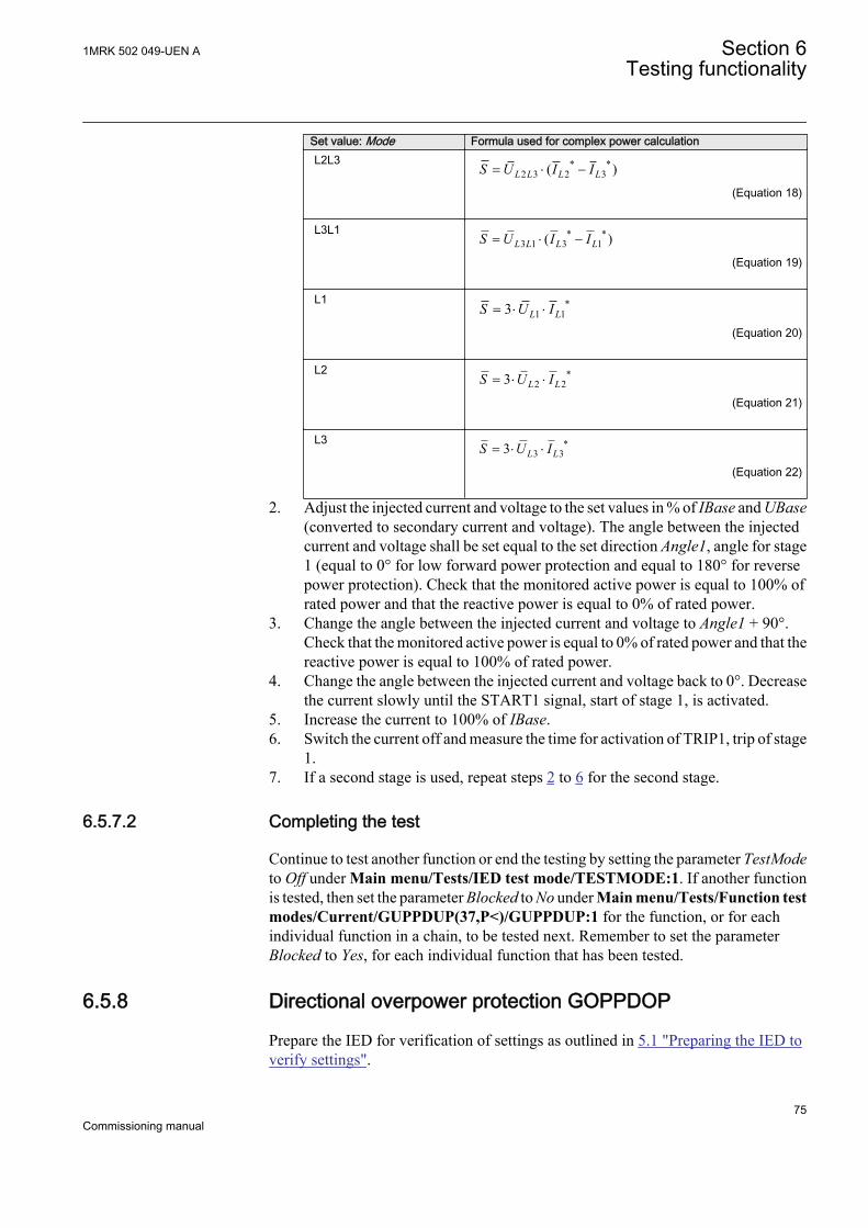
Set value: Mode Formula used for complex power calculationL2L3 * *
2 3 2 3( )L L L LS U I I= × -
EQUATION1701 V1 EN (Equation 18)
L3L1 * *3 1 3 1( )L L L LS U I I= × -
EQUATION1702 V1 EN (Equation 19)
L1 *1 13 L LS U I= × ×
EQUATION1703 V1 EN (Equation 20)
L2 *2 23 L LS U I= × ×
EQUATION1704 V1 EN (Equation 21)
L3 *3 33 L LS U I= × ×
EQUATION1705 V1 EN (Equation 22)
2. Adjust the injected current and voltage to the set values in % of IBase and UBase(converted to secondary current and voltage). The angle between the injectedcurrent and voltage shall be set equal to the set direction Angle1, angle for stage1 (equal to 0° for low forward power protection and equal to 180° for reversepower protection). Check that the monitored active power is equal to 100% ofrated power and that the reactive power is equal to 0% of rated power.
3. Change the angle between the injected current and voltage to Angle1 + 90°.Check that the monitored active power is equal to 0% of rated power and that thereactive power is equal to 100% of rated power.
4. Change the angle between the injected current and voltage back to 0°. Decreasethe current slowly until the START1 signal, start of stage 1, is activated.
5. Increase the current to 100% of IBase.6. Switch the current off and measure the time for activation of TRIP1, trip of stage
1.7. If a second stage is used, repeat steps 2 to 6 for the second stage.
6.5.7.2 Completing the test
Continue to test another function or end the testing by setting the parameter TestModeto Off under Main menu/Tests/IED test mode/TESTMODE:1. If another functionis tested, then set the parameter Blocked to No under Main menu/Tests/Function testmodes/Current/GUPPDUP(37,P<)/GUPPDUP:1 for the function, or for eachindividual function in a chain, to be tested next. Remember to set the parameterBlocked to Yes, for each individual function that has been tested.
6.5.8 Directional overpower protection GOPPDOP
Prepare the IED for verification of settings as outlined in 5.1 "Preparing the IED toverify settings".
1MRK 502 049-UEN A Section 6Testing functionality
75Commissioning manual

Values of the logical signals for GOPPDOP are available on the local HMI underMain menu/Tests/Function status/Current/GOPPDOP(32,P>)/GOPPDOP:X.The Signal Monitoring in PCM600 shows the same signals that are available on thelocal HMI.
6.5.8.1 Verifying the settings
The overpower protection shall be set to values according to the real set values to beused. The test is made by means of injection of voltage and current where theamplitude of both current and voltage and the phase angle between the voltage andcurrent can be controlled. During the test the analog outputs of active and reactivepower shall be monitored.
1. Connect the test set for injection of voltage and current corresponding to themode to be used in the application. If a three phase test set is available this couldbe used for all the modes. If a single phase current/voltage test set is available thetest set should be connected to a selected input for one phase current and voltage.Use the formulas stated in Table 3 for the different calculation modes used. Theset mode Mode can be found under Main menu/Settings/IED Settings/Current/GOPPDOP(32,P>)/GOPPDOP:1/General.
2. Adjust the injected current and voltage to the set rated values in % of IBase andUBase (converted to secondary current and voltage). The angle between theinjected current and voltage shall be set equal to the set direction Angle1, anglefor stage 1 (equal to 0° for low forward power protection and equal to 180° forreverse power protection). Check that the monitored active power is equal to100% of rated power and that the reactive power is equal to 0% of rated power.
3. Change the angle between the injected current and voltage to Angle1 + 90°.Check that the monitored active power is equal to 0% of rated power and that thereactive power is equal to 100% of rated power.
4. Change the angle between the injected current and voltage back to Angle1 value.Increase the current slowly from 0 until the START1 signal, start of stage 1, isactivated. Check the injected power and compare it to the set value Power1,power setting for stage 1 in % of Sbase.
5. Increase the current to 100% of IBase and switch the current off.6. Switch the current on and measure the time for activation of TRIP1, trip of stage
1.7. If a second stage is used, repeat steps 2 to 6 for the second stage.
6.5.8.2 Completing the test
Continue to test another function or end the testing by setting the parameter TestModeto Off under Main menu/Tests/IED test mode/TESTMODE:1. If another functionis tested, then set the parameter Blocked to No under Main menu/Tests/Function testmodes/Current/GOPPDOP(32,P>)/GOPPDOP:X for the function, or for eachindividual function in a chain, to be tested next. Remember to set the parameterBlocked to Yes, for each individual function that has been tested.
Section 6 1MRK 502 049-UEN ATesting functionality
76Commissioning manual

6.5.9 Accidental energizing protection for synchronous generatorAEGGAPC
Prepare the IED for verification of settings as outlined in 5.1 "Preparing the IED toverify settings".
Values of the logical signals for AEGGAPC are available on the local HMI underMain menu/Tests/Function status/Current/AEGGAPC(50AE,U<&I>)/AEGGAPC:1. The Signal Monitoring in PCM600 shows the same signals that areavailable on the local HMI.
6.5.9.1 Verifying the settings
1. Connect the test set for three-phase current injection and for three phase voltageinjection to the appropriate IED terminals.
2. Inject zero voltage to the IED.3. Increase the injected symmetric three phase current slowly and note the operated
value (start value).4. Decrease the current slowly and note the reset value.5. Connect a trip output contact to a timer.6. Set the injected current to 200% of the operate level, switch on the current and
check the time delay.7. Check that all trip and start contacts operate according to the configuration
(signal matrises).8. Finally check that start and trip information is stored in the event menu.9. Inject rated symmetric three phase voltage to the IED.10. Set the injected current to 200% of the operate level, switch on the current. The
function shall not start and trip.11. Inject 95% of the set ArmU< value symmetric three-phase voltage to the IED.12. Set the injected current to 200% of the operate level, switch on the current. The
function shall start and trip.
6.5.10 Negative-sequence time overcurrent protection for machinesNS2PTOC
Prepare the IED for verification of settings as outlined in 5.1 "Preparing the IED toverify settings".
Values of the logical signals for NS2PTOC are available on the local HMI under Mainmenu/Tests/Function status/Current/NS2PTOC(46I2,2I2>)/NS2PTOC:1. TheSignal Monitoring in PCM600 shows the same signals that are available on the localHMI.
6.5.10.1 Verifying settings by secondary injection
1MRK 502 049-UEN A Section 6Testing functionality
77Commissioning manual

1. Connect the test set for injection of three-phase currents to the appropriatecurrent terminals of the IED.
2. Go to Main menu/Settings/IED Settings/Current/NS2PTOC(46I2,2I2>)/NS2PTOC:1/General and make sure that the function is enabled, that isOperation is set to On.
3. Inject current into IEDs in such a way that negative sequence component iscreated and then verify that negative sequence component of the injectedcurrents is calculated correctly by the function. See example below for 1 A ratedcurrent transformer.
4. Inject pure negative sequence current, that is, phase currents with exactly samemagnitude, reversed sequence and exactly 120° phase displaced into the IEDwith an initial value below negative sequence current start level. No outputsignals should be activated.Note: If it is difficult to obtain pure negative sequence current for the secondaryinjection test, a current corresponding to the two phase short-circuit conditioncan be used. A two phase short-circuit gives a negative sequence current of amagnitude: magnitude = (1/√3) · fault current.
5. Increase the injected current and note the value at which the step 1 of the functionoperates. Start signal ST1 must be activated when amplitude of the negativesequence current lies slightly above the start level I2-1>. Corresponding tripsignals TR1 and TRIP is activated after the pre-set time delay has expired.Note: Block or disable operation of step 2 when testing step 1 if the injectedcurrent activates the step 2.
6. Decrease the current slowly and note the reset value.7. Connect a trip output contact to a timer.8. Set the current to 200 % of the start level of the step 1, switch on the current and
check the definite time delay for trip signals TR1 and TRIP. Once the measurednegative sequence current exceeds the set start level I2-1>, the settable definitetimer t1 starts to count and trip signals is released after the set time delay haselapsed. The same test must be carried out to check the accuracy of definite timedelay for ALARM signal.Note: The output ALARM is operated by START signal.
9. If inverse time is selected the trip signals TR1 and TRIP operates after a timecorresponding to the formula:
t s
I
[ ]
( )
=
− >
⋅
1
2 1
100
2
2
Multiple of StartKK
This means that if current jumps from 0 to 2 times start and negative sequencecapability value of generator K1 is set to 10 sec and current start level I2-1> is
Section 6 1MRK 502 049-UEN ATesting functionality
78Commissioning manual
set to 10% of rated generator current, then TR1 and TRIP signals operates at timeequal to 250 sec ± tolerance.
10. Repeat the above-described tests for the step 2 of the function excluding theinverse time testing.
11. Finally check that start and trip information is stored in the event menu.
ExampleIf CT ratios CTprim/CTsec for all three phases are 1000 and IBase is set to 1000 A,than the following secondary currents shall be applied.
IL1 Ampl = 1.1 A Angl = 15 deg
IL2 Ampl = 0.6 A Angl = 97 deg
IL3 Ampl = 1.3 A Angl = -135 deg
The service value output NSCURR indicating amplitude of negative sequence currentin primary amperes should be 962A approximative.
6.5.11 Voltage-restrained time overcurrent protection VRPVOC
Prepare the IED for verification of settings as outlined in 5.1 "Preparing the IED toverify settings".
Values of the logical signals for VRPVOC are available on the local HMI under Mainmenu/Tests/Function status/Current/VRPVOC(51V,I>U<)/VRPVOC:1. TheSignal Monitoring in PCM600 shows the same signals that are available on the localHMI.
6.5.11.1 Verifying the settings
Built-in overcurrent feature (non-directional)
1. Go to Main menu/Test/Function test modes/Current protection and makesure that VRPVOC to be tested is unblocked and other functions that mightdisturb the evaluation of the test are blocked.
2. Connect the test set for injection of three-phase currents to the appropriatecurrent terminals of the IED.
3. Inject three-phase current(s). Increase the current(s) until the function operatesand check against the set operate value, for example when voltage is reduced to50% of rated the overcurrent start shall be 50% of the current start value for ratedvoltage.
4. Decrease the current slowly and check the reset value.5. Connect a TRIP output contact to the timer.6. Set the current to 200% of the operate value, switch on the current and check the
time delay.
1MRK 502 049-UEN A Section 6Testing functionality
79Commissioning manual

For inverse time curves, check the operate time at a current equal to 110% of theoperate current at tMin.
7. Check that TRIP and START contacts operate according to the configurationlogic.
8. Finally check that START and TRIP information is stored in the event menu, ifthe signals have been configured towards the disturbance recordingfunctionality.
Information on how to use the event menu is found in theoperators manual.
Overcurrent feature with voltage restraint
1. Connect the test set for injection of three-phase currents and three-phasevoltages to the appropriate current and voltage terminals of the IED.
2. Inject the rated voltage during the next steps in order for function to operateproperly.
3. Inject three-phase current(s) and voltage(s).Overall check in principle as non-directional overcurrent feature.
4. Operate value measurementThe relevant voltage restraining value must also be injected from the test set andthe influence on the operate value has to be calculated when testing the operatevalue is completed.
5. Operate time measurementDefinite times may be tested as above. For inverse time characteristics theSTART value, to which the overcurrent ratio has to be calculated, is the actualstart value as got with actual restraining from the voltage restraining quantity.
6.5.11.2 Completing the test
Continue to test another function or end the testing by setting the parameter TestModeto Off under Main menu/Tests/IED test mode/TESTMODE:1. If another functionis tested, then set the parameter Blocked to No under Main menu/Tests/Function testmodes/Current/VRPVOC(51V,I>U<)/VRPVOC:1 for the function, or for eachindividual function in a chain, to be tested next. Remember to set the parameterBlocked to Yes, for each individual function that has been tested.
6.6 Testing voltage protection functions
6.6.1 Two step undervoltage protection UV2PTUV
Prepare the IED for verification of settings as outlined in 5.1 "Preparing the IED toverify settings".
Section 6 1MRK 502 049-UEN ATesting functionality
80Commissioning manual

Values of the logical signals for UV2PTUV are available on the local HMI underMain menu/Tests/Function status/Voltage/UV2PTUV(27,2U<)/UV2PTUV:1.The Signal Monitoring in PCM600 shows the same signals that are available on thelocal HMI.
6.6.1.1 Verifying the setting
Verification of START value and time delay to operate for Step 1
1. Check that the IED settings are appropriate, especially the START value, thedefinite time delay and the 1 out of 3 operation mode.
2. Supply the IED with three-phase voltages at their rated values.3. Slowly decrease the voltage in one of the phases, until the START signal
appears.4. Note the operate value and compare it with the set value.
The operate value in secondary volts is calculated according tothe following equations:
For phase-to-ground measurement:
U UBase VT
VTprim
1
100 3
<× ×
sec
IECEQUATION2430 V1 EN (Equation 23)
For phase-to-phase measurement:
UUBase
VT
VTprim
1
100
<× ×
sec
IECEQUATION2431 V1 EN (Equation 24)5. Increase the measured voltage to rated load conditions.6. Check that the START signal resets.7. Instantaneously decrease the voltage in one phase to a value about 20% lower
than the measured operate value.8. Measure the time delay for the TRIP signal, and compare it with the set value.9. Check the inverse time delay by injecting a voltage corresponding to 0.8 × U1<.
For example, if the inverse time curve A is selected, the tripsignals TR1 and TRIP operate after a time corresponding to theequation:
t sk
U
U
( ) =−
<
1
11
IECEQUATION2428 V1 EN (Equation 25)
where:
t(s) Operate time in seconds
1MRK 502 049-UEN A Section 6Testing functionality
81Commissioning manual
k1 Settable time multiplier of the function for step 1
U Measured voltage
U1< Set start voltage for step 1
For example, if the measured voltage jumps from the rated value to 0.8 times theset start voltage level and time multiplier k1 is set to 0.05 s (default value), thenthe TR1 and TRIP signals operate at a time equal to 0.250 s ± tolerance.
10. The test above can be repeated to check the inverse time characteristic atdifferent voltage levels.
11. Repeat the above-described steps for step 2.
Extended testing
1. The tests above can be repeated for 2 out of 3 and for 3 out of 3 operation mode.
6.6.1.2 Completing the test
Continue to test another function or end the testing by setting the parameter TestModeto Off under Main menu/Tests/IED test mode/TESTMODE:1. If another functionis tested, then set the parameter Blocked to No under Main menu/Tests/Function testmodes/Voltage/UV2PTUV(27,2U<)/UV2PTUV:1 for the function, or for eachindividual function in a chain, to be tested next. Remember to set the parameterBlocked to Yes, for each individual function that has been tested.
6.6.2 Two step overvoltage protection OV2PTOV
Prepare the IED for verification of settings as outlined in 5.1 "Preparing the IED toverify settings".
Values of the logical signals for OV2PTOV are available on the local HMI underMain menu/Tests/Function status/Voltage/OV2PTOV(59,2U>)/OV2PTOV:1.The Signal Monitoring in PCM600 shows the same signals that are available on thelocal HMI.
6.6.2.1 Verification of single-phase voltage and time delay to operate for Step1
1. Apply single-phase voltage below the set value U1>.2. Slowly increase the voltage until the ST1 signal appears.3. Note the operate value and compare it with the set value.
The operate value in secondary volts is calculated according tothe following equations:
Section 6 1MRK 502 049-UEN ATesting functionality
82Commissioning manual

For phase-to-ground measurement:
U UBase VT
VTprim
1
100 3
>× ×
sec
IECEQUATION2426 V1 EN (Equation 26)
For phase-to-phase measurement:
UUBase
VT
VTprim
1
100
>× ×
sec
IECEQUATION2427 V1 EN (Equation 27)4. Decrease the voltage slowly and note the reset value.5. Set and apply about 20% higher voltage than the measured operate value for one
phase.6. Measure the time delay for the TR1 signal and compare it with the set value.7. Check the inverse time delay by injecting a voltage corresponding to 1.2 × U1>.
For example, if the inverse time curve A is selected, the tripsignals TR1 and TRIP operate after a time corresponding to theequation:
t sk
U
U
( ) =
>−
1
11
IECEQUATION2429 V1 EN (Equation 28)
where:
t(s) Operate time in seconds
k1 Settable time multiplier of the function for step 1
U Measured voltage
U1> Set start voltage for step 1
For example, if the measured voltage jumps from 0 to 1.2 times the set startvoltage level and time multiplier k1 is set to 0.05 s (default value), then the TR1and TRIP signals operate at a time equal to 0.250 s ± tolerance.
8. The test above can be repeated to check the inverse time characteristic atdifferent voltage levels.
9. Repeat the above-described steps for step 2.
6.6.2.2 Completing the test
Continue to test another function or end the testing by setting the parameter TestModeto Off under Main menu/Tests/IED test mode/TESTMODE:1. If another functionis tested, then set the parameter Blocked to No under Main menu/Tests/Function testmodes/Voltage/OV2PTOV(59,2U>)/OV2PTOV:1 for the function, or for eachindividual function in a chain, to be tested next. Remember to set the parameterBlocked to Yes, for each individual function that has been tested.
1MRK 502 049-UEN A Section 6Testing functionality
83Commissioning manual

6.6.3 Two step residual overvoltage protection ROV2PTOV
Prepare the IED for verification of settings as outlined in 5.1 "Preparing the IED toverify settings".
Values of the logical signals for ROV2PTOV are available on the local HMI underMain menu/Tests/Function status/Voltage/ROV2PTOV(59N,2UN>)/ROV2PTOV:1. The Signal Monitoring in PCM600 shows the same signals that areavailable on the local HMI.
6.6.3.1 Verifying the settings
1. Apply the single-phase voltage either to a single-phase voltage input or to aresidual voltage input with the start value below the set value U1>.
2. Slowly increase the value until ST1 appears.3. Note the operate value and compare it with the set value.4. Decrease the voltage slowly and note the reset value.5. Set and apply about 20% higher voltage than the measured operate value for one
phase.6. Measure the time delay for the TR1 signal and compare it with the set value.7. Check the inverse time delay by injecting a voltage corresponding to 1.2 × U1>.
For example, if the inverse time curve A is selected, the tripsignals TR1 and TRIP operate after a time corresponding to theequation:
t sk
U
U
( ) =
>−
1
11
IECEQUATION2429 V1 EN (Equation 29)
where:
t(s) Operate time in seconds
k1 Settable time multiplier of the function for step 1
U Measured voltage
U1> Set start voltage for step 1
For example, if the measured voltage jumps from 0 to 1.2 times the set startvoltage level and time multiplier k1 is set to 0.05 s (default value), then the TR1and TRIP signals operate at a time equal to 0.250 s ± tolerance.
8. Repeat the test for step 2.
Section 6 1MRK 502 049-UEN ATesting functionality
84Commissioning manual

6.6.3.2 Completing the test
Continue to test another function or end the testing by setting the parameter TestModeto Off under Main menu/Tests/IED test mode/TESTMODE:1. If another functionis tested, then set the parameter Blocked to No under Main menu/Tests/Function testmodes/Voltage/ROV2PTOV(59N,2UN>)/ROV2PTOV:1 for the function, or foreach individual function in a chain, to be tested next. Remember to set the parameterBlocked to Yes, for each individual function that has been tested.
6.6.4 Overexcitation protection OEXPVPH
Prepare the IED for verification of settings as outlined in 5.1 "Preparing the IED toverify settings".
Values of the logical signals for OEXPVPH are available on the local HMI underMain menu/Tests/Function status/Voltage/OEXPVPH(24,U/f>)/OEXPVPH:1.The Signal Monitoring in PCM600 shows the same signals that are available on thelocal HMI.
6.6.4.1 Verifying the settings
1. Enable function.2. Connect a symmetrical three-phase voltage input from the test set to the
appropriate connection terminals of the overexcitation protection OEXPVPH.OEXPVPH is conveniently tested using rated frequency for the injection voltageand increasing the injection voltage to get the desired overexcitation level.
3. Connect the alarm contact to the timer and set the time delay tAlarm temporarilyto zero.
4. Increase the voltage and note the operate value V/Hz>.5. Reduce the voltage slowly and note the reset value.6. Set the alarm time delay to the correct value according to the setting plan and
check the time delay, injecting a voltage corresponding to 1.2 · V/Hz>.7. Connect a trip output contact to the timer and temporarily set the time delay tMin
to 0.5s.8. Increase the voltage and note the V/Hz>> operate value9. Reduce the voltage slowly and note the reset value.10. Set the time delay to the correct value according to the setting plan and check the
time delay tMin, injecting a voltage corresponding to 1.2 · V/Hz>>.11. Check that trip and alarm contacts operate according to the configuration logic.12. Finally check that START and TRIP information is stored in the event menu.
6.6.4.2 Completing the test
Continue to test another function or end the testing by setting the parameter TestModeto Off under Main menu/Tests/IED test mode/TESTMODE:1. If another functionis tested, then set the parameter Blocked to No under Main menu/Tests/Function test
1MRK 502 049-UEN A Section 6Testing functionality
85Commissioning manual

modes/Voltage/OEXPVPH(24,U/f>)/OEXPVPH:1 for the function, or for eachindividual function in a chain, to be tested next. Remember to set the parameterBlocked to Yes, for each individual function that has been tested.
6.6.5 100% Stator earth fault protection, 3rd harmonic basedSTEFPHIZ
Prepare the IED for verification of settings as outlined in 5.1 "Preparing the IED toverify settings".
Values of the logical signals for STEFPHIZ are available on the local HMI underMain menu/Tests/Function status/Voltage/STEFPHIZ(59THD)/STEFPHIZ:1.The Signal Monitoring in PCM600 shows the same signals that are available on thelocal HMI.
6.6.5.1 Testing
The protection function uses measurement of the third-harmonic voltages in theneutral point of the generator and on the generator terminal (broken delta voltagetransformer connection to the IED).
The test set shall be capable to generate third-harmonic voltages. One voltage (UN3)is connected to the residual voltage input related to the terminal side of the generator.The second voltage (UN3) is connected to the voltage input related to the neutral of thegenerator. The angle between the injected third-harmonic voltages shall be adjustable.
en07000127.vsd
U3N
U3T
IEC07000127 V1 EN
Figure 18: Typical phasor diagram for third harmonic voltages for healthymachine
1. Inject the following voltages: U3T = 15 V, U3N = 5 V and the angle between thevoltages = 180°. Check the monitored values of the following analogue signals:E3 (the magnitude of the third-harmonic induced voltage in the stator), U3N: 5 V(the magnitude of the third-harmonic voltage measured at the neutral side of thegenerator), U3T: 15 V (the magnitude of the third-harmonic voltage measured atthe terminal side of the generator) and ANGLE: 180° (the angle between the
Section 6 1MRK 502 049-UEN ATesting functionality
86Commissioning manual
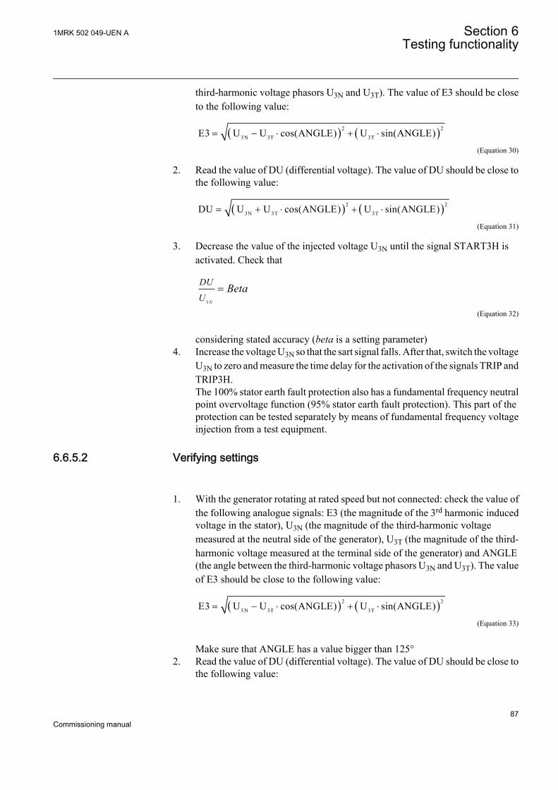
third-harmonic voltage phasors U3N and U3T). The value of E3 should be closeto the following value:
( ) ( )2 2
3N 3T 3TE3 U U cos(ANGLE) U sin(ANGLE)= - × + ×
EQUATION2070 V1 EN (Equation 30)
2. Read the value of DU (differential voltage). The value of DU should be close tothe following value:
( ) ( )2 2
3N 3T 3TDU U U cos(ANGLE) U sin(ANGLE)= + × + ×
EQUATION2071 V1 EN (Equation 31)
3. Decrease the value of the injected voltage U3N until the signal START3H isactivated. Check that
3 N
DU
UBeta=
EQUATION2072 V2 EN (Equation 32)
considering stated accuracy (beta is a setting parameter)4. Increase the voltage U3N so that the sart signal falls. After that, switch the voltage
U3N to zero and measure the time delay for the activation of the signals TRIP andTRIP3H.The 100% stator earth fault protection also has a fundamental frequency neutralpoint overvoltage function (95% stator earth fault protection). This part of theprotection can be tested separately by means of fundamental frequency voltageinjection from a test equipment.
6.6.5.2 Verifying settings
1. With the generator rotating at rated speed but not connected: check the value ofthe following analogue signals: E3 (the magnitude of the 3rd harmonic inducedvoltage in the stator), U3N (the magnitude of the third-harmonic voltagemeasured at the neutral side of the generator), U3T (the magnitude of the third-harmonic voltage measured at the terminal side of the generator) and ANGLE(the angle between the third-harmonic voltage phasors U3N and U3T). The valueof E3 should be close to the following value:
( ) ( )2 2
3N 3T 3TE3 U U cos(ANGLE) U sin(ANGLE)= - × + ×
EQUATION2076 V1 EN (Equation 33)
Make sure that ANGLE has a value bigger than 125°2. Read the value of DU (differential voltage). The value of DU should be close to
the following value:
1MRK 502 049-UEN A Section 6Testing functionality
87Commissioning manual

( ) ( )2 2
3N 3T 3TDU U U cos(ANGLE) U sin(ANGLE)= + × + ×
EQUATION2078 V1 EN (Equation 34)
3. Read the value of BU (bias voltage: Beta ·U3N). The ratio DU/BU should be wellbelow 1 for a non-faulted generator.
4. After synchronization of the generator the ratio DU/BU is checked for differentload levels of the generator. These different monitoring of load levels should bethe base for the setting of beta.If the function is used with the option of neutral point measurement only the testis performed by check of this voltage. The operate value should be above themeasured residual third-harmonic voltage in the neutral point at normaloperation (non-faulted generator).
6.6.5.3 Completing the test
Continue to test another function or end the testing by setting the parameter TestModeto Off under Main menu/Tests/IED test mode/TESTMODE:1. If another functionis tested, then set the parameter Blocked to No under Main menu/Tests/Function testmodes/Voltage/STEFPHIZ(59THD)/STEFPHIZ:1 for the function, or for eachindividual function in a chain, to be tested next. Remember to set the parameterBlocked to Yes, for each individual function that has been tested.
Generator rotor winding and its associated dc supply electric circuit is typically fullyinsulated from the earth. Therefore single connection of this circuit to earth will notcause flow of any substantial current. However, if second earth-fault appears in thiscircuit circumstances can be quit serious. Depending on the location of these twofaults such operating condition may cause:
• Partial or total generator loss of field• Large dc current flow through rotor magnetic circuit• Rotor vibration• Rotor displacement sufficient to cause stator mechanical damage
Therefore practically all bigger generators have some dedicated protection which iscapable to detect the first earth-fault in the rotor circuit and then, depending on thefault resistance, either just to give an alarm to the operating personnel or actually togive stop command to the machine.
Rotor earth fault protection can be integrated in the IED among allother protection functions typically required for generator protection.Instruction 1MRG001910 gives an example of a testing procedure byusing COMBIFLEX injection unit RXTTE4.
Section 6 1MRK 502 049-UEN ATesting functionality
88Commissioning manual

6.7 Testing frequency protection functions
6.7.1 Underfrequency protection SAPTUF
Prepare the IED for verification of settings as outlined in 5.1 "Preparing the IED toverify settings".
Values of the logical signals for SAPTUF are available on the local HMI under Mainmenu/Tests/Function status/Frequency/SAPTUF(81,f<)/SAPTUF:X. The SignalMonitoring in PCM600 shows the same signals that are available on the local HMI.
6.7.1.1 Verifying the settings
Verification of START value and time delay to operate
1. Check that the IED settings are appropriate, for example the start value and thetime delay.
2. Supply the IED with three-phase voltages at their rated values and initialfrequency.The initial frequency is calculated using Equation 35.
0.02 / 0.04 0.04rStartFrequency floor f StartFrequency
IECEQUATION16059 V1 EN (Equation 35)[1]
3. Slowly decrease the voltage frequency by steps of 40 mHz until the STARTsignal appears; during each step apply the voltage signal for a time that is eitherat least 10% longer than (tDelay+100 ms) or a suitable time to monitor thefunction.
4. Note the frequency value at which the START signal appears and compare itwith the set value StartFrequency.
5. Increase the frequency until its rated value is reached.6. Check that the START signal resets.7. Supply the IED with three-phase voltages at their rated values and frequency 20
mHz over the set value StartFrequency.8. Decrease the frequency with a 40 mHz step, applying it for a time that is at least
10% longer than (tDelay+100 ms).9. Measure the time delay of the TRIP signal, and compare it with the set value
tDelay. Note that the measured time consists of the set value of the time delayplus the minimum operate time of the function (80 - 90 ms).
Extended testing
[1] floor[x] is the largest integer less than or equal to x
1MRK 502 049-UEN A Section 6Testing functionality
89Commissioning manual

1. Check that the IED settings are appropriate, for example the start value and thetime delay.
2. Supply the IED with three-phase voltages at their rated values and frequency 20mHz under the set value StartFrequency, applying it for a time that is at least10% longer than (tDelay+100 ms).
3. Verify that the TRIP signal is active.4. Increase the frequency with a 40 mHz step, applying it until the TRIP signal
resets.5. Measure the reset time of the TRIP signal, and compare it with the technical data
of the function.
Verification of the low voltage magnitude blocking
1. Check that the IED settings are appropriate, especially the StartFrequency andthe tDelay in SAPTUF, and the GlobalBaseSel and the MinValFreqMeas in theSMAI preprocessing function.
2. Supply the IED with three-phase voltages at rated values.3. Slowly decrease the magnitude of the applied voltage until the BLKDMAGN
signal appears.4. Note the voltage magnitude value and compare it with the value
MinValFreqMeas x UBase / 100.Where:• MinValFreqMeas is a set value of the SMAI.• UBase is the value in the GBASVAL group identified by the setting
GlobalBaseSel.5. Slowly decrease the frequency of the applied voltage, to a value below
StartFrequency as explained in Section "Verification of START value and timedelay to operate".
6. Check that the START signal does not appear.7. Wait for a time corresponding to (tDelay+100 ms), and check that the TRIP
signal does not appear.8. Slowly increase the magnitude of the applied voltages until the BLKDMAGN
signal resets.9. Verify that the signal START appears and wait for a time at least equal to (tDelay
+100 ms) to verify that also the signal TRIP becomes active.
6.7.1.2 Completing the test
Continue to test another function or end the testing by setting the parameter TestModeto Off under Main menu/Tests/IED test mode/TESTMODE:1. If another functionis tested, then set the parameter Blocked to No under Main menu/Tests/Function testmodes/Frequency/SAPTUF(81,f<)/SAPTUF:X for the function, or for eachindividual function in a chain, to be tested next. Remember to set the parameterBlocked to Yes, for each individual function that has been tested.
Section 6 1MRK 502 049-UEN ATesting functionality
90Commissioning manual

6.7.2 Overfrequency protection SAPTOF
Prepare the IED for verification of settings as outlined in 5.1 "Preparing the IED toverify settings".
Values of the logical signals for SAPTOF are available on the local HMI under Mainmenu/Tests/Function status/Frequency/SAPTOF(81,f>)/SAPTOF:X. The SignalMonitoring in PCM600 shows the same signals that are available on the local HMI.
6.7.2.1 Verifying the settings
Verification of START value and time delay to operate
1. Check that the IED settings are appropriate, for example the start value and thetime delay.
2. Supply the IED with three-phase voltages at their rated values and initialfrequency.The initial frequency is calculated using Equation 36.
0.02 / 0.04 0.04rStartFrequency floor f StartFrequency
IECEQUATION16061 V1 EN (Equation 36)[2]
3. Slowly increase the voltage frequency by steps of 40 mHz until the STARTsignal appears; during each step apply the voltage signal for a time that is eitherat least 10% longer than (tDelay+100 ms) or a suitable time to monitor thefunction.
4. Note the frequency value at which the START signal appears and compare itwith the set value StartFrequency.
5. Decrease the frequency until its rated value is reached.6. Check that the START signal resets.7. Supply the IED with three-phase voltages at their rated values and frequency 20
mHz under the set value StartFrequency.8. Increase the frequency with a 40 mHz step, applying it for a time that is at least
10% longer than (tDelay+100 ms).9. Measure the time delay of the TRIP signal, and compare it with the set value
tDelay. Note that the measured time consists of the set value of the time delayplus the minimum operate time of the function (80 - 90 ms).
Extended testing
[2] floor[x] is the largest integer less than or equal to x
1MRK 502 049-UEN A Section 6Testing functionality
91Commissioning manual

1. Check that the IED settings are appropriate, for example the start value and thetime delay.
2. Supply the IED with three-phase voltages at their rated values and frequency 20mHz over the set value StartFrequency, applying it for a time that is at least 10%longer than (tDelay+100 ms).
3. Verify that the TRIP signal is active.4. Decrease the frequency with a 40 mHz step, applying it until the TRIP signal
resets.5. Measure the reset time of the TRIP signal, and compare it with the technical data
of the function.
Verification of the low voltage magnitude blocking
1. Check that the IED settings are appropriate, especially the StartFrequency andthe tDelay in SAPTOF, and the GlobalBaseSel and the MinValFreqMeas in theSMAI preprocessing function.
2. Supply the IED with three-phase voltages at rated values.3. Slowly decrease the magnitude of the applied voltage until the BLKDMAGN
signal appears.4. Note the voltage magnitude value and compare it with the value
MinValFreqMeas x UBase / 100.Where:• MinValFreqMeas is a set value of the SMAI.• UBase is the value in the GBASVAL group identified by the setting
GlobalBaseSel.5. Slowly increase the frequency of the applied voltage, to a value above
StartFrequency as explained in Section Verification of START value and timedelay to operate.
6. Check that the START signal does not appear.7. Wait for a time corresponding to (tDelay+100 ms), and check that the TRIP
signal does not appear.8. Slowly increase the magnitude of the applied voltages until the BLKDMAGN
signal resets.9. Verify that the signal START appears and wait for a time at least equal to (tDelay
+100 ms) to verify that also the signal TRIP becomes active.
6.7.2.2 Completing the test
Continue to test another function or end the testing by setting the parameter TestModeto Off under Main menu/Tests/IED test mode/TESTMODE:1. If another functionis tested, then set the parameter Blocked to No under Main menu/Tests/Function testmodes/Frequency/SAPTOF(81,f>)/SAPTOF:X for the function, or for eachindividual function in a chain, to be tested next. Remember to set the parameterBlocked to Yes, for each individual function that has been tested.
Section 6 1MRK 502 049-UEN ATesting functionality
92Commissioning manual

6.7.3 Rate-of-change frequency protection SAPFRC
Prepare the IED for verification of settings as outlined in 5.1 "Preparing the IED toverify settings".
Values of the logical signals for SAPFRC are available on the local HMI under Mainmenu/Tests/Function status/Frequency/SAPFRC(81,df/dt)/SAPFRC:X. TheSignal Monitoring in PCM600 shows the same signals that are available on the localHMI.
6.7.3.1 Verifying the settings
Verification of START value and time delay to operate
1. Check that the appropriate settings are available in the IED, especially theSTART value and the definite time delay. Set StartFreqGrad, to a rather smallnegative value.
2. Supply the IED with three-phase voltages at their rated values.3. Slowly decrease the frequency of the applied voltage, with an increasing rate-of-
change that finally exceeds the setting of StartFreqGrad, and check that theSTART signal appears.
4. Note the operate value and compare it with the set value.5. Increase the frequency to rated operating conditions, and zero rate-of-change.6. Check that the START signal resets.7. Instantaneously decrease the frequency of the applied voltage to a value about
20% lower than the nominal value.8. Measure the time delay for the TRIP signal, and compare it with the set value.
Extended testing
1. The test above can be repeated to check a positive setting of StartFreqGrad.2. The tests above can be repeated to test the RESTORE signal, when the frequency
recovers from a low value.
6.7.3.2 Completing the test
Continue to test another function or end the testing by setting the parameter TestModeto Off under Main menu/Tests/IED test mode/TESTMODE:1. If another functionis tested, then set the parameter Blocked to No under Main menu/Tests/Function testmodes/Frequency/SAPFRC(81,df/dt)/SAPFRC:X for the function, or for eachindividual function in a chain, to be tested next. Remember to set the parameterBlocked to Yes, for each individual function that has been tested.
1MRK 502 049-UEN A Section 6Testing functionality
93Commissioning manual

6.8 Testing secondary system supervision functions
6.8.1 Fuse failure supervision SDDRFUF
Prepare the IED for verification of settings as outlined in 5.1 "Preparing the IED toverify settings".
Values of the logical signals for SDDRFUF are available on the local HMI underMain menu/Tests/Function status/Secondary system supervision/SDDRFUF/SDDRFUF:1. The Signal Monitoring in PCM600 shows the same signals that areavailable on the local HMI.
The verification is divided in two main parts. The first part is common to all fusefailure supervision options, and checks that binary inputs and outputs operate asexpected according to actual configuration. In the second part the relevant set operatevalues are measured.
6.8.1.1 Checking that the binary inputs and outputs operate as expected
1. Simulate normal operating conditions with the three-phase currents in phasewith their corresponding phase voltages and with all of them equal to their ratedvalues.
2. Connect the nominal dc voltage to the DISCPOS binary input.• The signal BLKU should appear with almost no time delay.• No signals BLKZ and 3PH should appear on the IED.• Only the distance protection function can operate.• Undervoltage-dependent functions must not operate.
3. Disconnect the dc voltage from the DISCPOS binary input terminal.4. Connect the nominal dc voltage to the MCBOP binary input.
• The BLKU and BLKZ signals should appear without any time delay.• All undervoltage-dependent functions must be blocked.
5. Disconnect the dc voltage from the MCBOP binary input terminal.6. Disconnect one of the phase voltages and observe the logical output signals on
the binary outputs of the IED.BLKU and BLKZ signals should appear simultaneously wether the BLKU andBLKZ reset depends on the setting SealIn “on” or “off”. If “on” no reset, if “off”reset.
7. After more than 5 seconds disconnect the remaining two-phase voltages and allthree currents.• There should be no change in the high status of the output signals BLKU
and BLKZ.• The signal 3PH will appear.
8. Establish normal voltage and current operating conditions simultaneously andobserve the corresponding output signals.
Section 6 1MRK 502 049-UEN ATesting functionality
94Commissioning manual
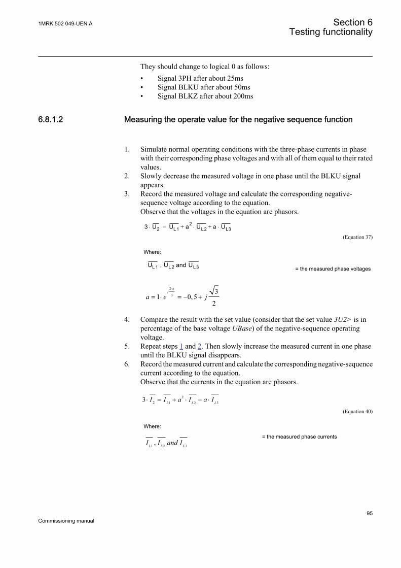
They should change to logical 0 as follows:• Signal 3PH after about 25ms• Signal BLKU after about 50ms• Signal BLKZ after about 200ms
6.8.1.2 Measuring the operate value for the negative sequence function
1. Simulate normal operating conditions with the three-phase currents in phasewith their corresponding phase voltages and with all of them equal to their ratedvalues.
2. Slowly decrease the measured voltage in one phase until the BLKU signalappears.
3. Record the measured voltage and calculate the corresponding negative-sequence voltage according to the equation.Observe that the voltages in the equation are phasors.
3 U2× UL1 a2 UL2 a+× UL3×+=
EQUATION707 V1 EN (Equation 37)
Where:
UL1 , UL2 and UL3
IEC00000275 V1 EN
= the measured phase voltages
2
33
1 0, 52
j
a e jp×
= × = - +
IECEQUATION00022 V1 EN
4. Compare the result with the set value (consider that the set value 3U2> is inpercentage of the base voltage UBase) of the negative-sequence operatingvoltage.
5. Repeat steps 1 and 2. Then slowly increase the measured current in one phaseuntil the BLKU signal disappears.
6. Record the measured current and calculate the corresponding negative-sequencecurrent according to the equation.Observe that the currents in the equation are phasors.
2
1 2 323 L L LI I a I a I× = + × + ×
IECEQUATION00021 V1 EN (Equation 40)
Where:
1 2 3L L LI I and I , IECEQUATION00020 V1 EN
= the measured phase currents
1MRK 502 049-UEN A Section 6Testing functionality
95Commissioning manual

2
33
1 0, 52
j
a e jp×
= × = - +
IECEQUATION00022 V1 EN
7. Compare the result with the set value of the negative-sequence operatingcurrent. Consider that the set value 3I2< is in percentage of the base currentIBase.
6.8.1.3 Measuring the operate value for the zero-sequence function
1. Simulate normal operating conditions with the three-phase currents in phasewith their corresponding phase voltages and with all of them equal to their ratedvalues.
2. Slowly decrease the measured voltage in one phase until the BLKU signalappears.
3. Record the measured voltage and calculate the corresponding zero-sequencevoltage according to the equation.Observe that the voltages in the equation are phasors.
3 U0× UL1 UL2 UL3+ +=
IEC00000276 V1 EN (Equation 43)
Where:
UL1 , UL2 and UL3
IEC00000275 V1 EN
= the measured phase voltages
4. Compare the result with the set value (consider that the set value 3U0> is inpercentage of the base voltage of the zero-sequence operating voltage.
5. Repeat steps 1 and 2. Then slowly increase the measured current in one phaseuntil the BLKU signal disappears.
6. Record the measured current and calculate the corresponding zero-sequencecurrent according to the equation.Observe that the currents in the equation are phasors.
0 L1 L2 L33 =I I I I× + +IECEQUATION00019 V1 EN (Equation 45)
Where:
1 2 3L L LI I and I , IECEQUATION00020 V1 EN
= the measured phase currents
7. Compare the result with the set value of the zero-sequence operating current.Consider that the set value 3I0< is in percentage of the base current IBase.
6.8.1.4 Checking the operation of the du/dt and di/dt based function
Section 6 1MRK 502 049-UEN ATesting functionality
96Commissioning manual

1. Simulate normal operating conditions with the three-phase currents in phasewith their corresponding phase voltages and with all of them equal to their ratedvalues.
2. Change the voltages and currents in all three phases simultaneously.The voltage change must be greater than the set value for DU> and the currentchange must be less than the set value for DI<.• The BLKU and BLKZ signals appear without any time delay. The BLKZ
signal will be activated only if the internal deadline detection is notactivated at the same time.
• 3PH should appear after 5 seconds, if the remaining voltage levels arelower than the set UDLD< of the DLD function.
3. Apply normal conditions as in step 1.The BLKU, BLKZ and 3PH signals should reset, if activated, see step 1 and 2.
4. Change the voltages and currents in all three phases simultaneously.The voltage change must be greater than the set value for DU> and the currentchange must be more than the set value for DI<.The BLKU, BLKZ and 3PH signals should not appear.
5. Repeat step 2.6. Connect the nominal voltages in all three phases and feed a current below the
operate level in all three phases.7. Keep the current constant. Disconnect the voltage in all three phases
simultaneously.The BLKU, BLKZ and 3PH signals should not appear.
8. Change the magnitude of the voltage and current for phase 1 to a value greaterthan the set value for DU> and DI<.
9. Check that the start output signals STDUL1 and STDIL1 and the general startsignals STDU or STDI are activated.
10. Check that the start output signals for the current and voltage phases 2 and 3 areactivated by changing the magnitude of the voltage and current for phases 2 and3.
6.8.1.5 Completing the test
Continue to test another function or end the testing by setting the parameter TestModeto Off under Main menu/Tests/IED test mode/TESTMODE:1. If another functionis tested, then set the parameter Blocked to No under Main menu/Tests/Function testmodes/Secondary system supervision/SDDRFUF/SDDRFUF:1 for the function,or for each individual function in a chain, to be tested next. Remember to set theparameter Blocked to Yes, for each individual function that has been tested.
1MRK 502 049-UEN A Section 6Testing functionality
97Commissioning manual

6.9 Testing control functions
During periods of frequent counter state/value changes, if theauxiliary power to the IED is interrupted, it is possible that thisinformation will be lost.
6.9.1 Synchrocheck, energizing check, and synchronizingSESRSYN
This section contains instructions on how to test the synchrocheck, energizing check,and synchronizing function SESRSYN for single, double and 1½ breakerarrangements.
This section contains instructions on how to test the synchrocheck and energizingcheck for single CB with or without the synchronizing function.
Prepare the IED for verification of settings as outlined in 5.1 "Preparing the IED toverify settings".
Values of the logical signals for SESRSYN are available on the local HMI under Mainmenu/Tests/Function status/Control/SESRSYN(25,SYNC)/SESRSYN:X. TheSignal Monitoring in PCM600 shows the same signals that are available on the localHMI.
At commissioning and periodical checks, the functions shall be tested with the usedsettings. To test a specific function, it might be necessary to change some settingparameters, for example:
• AutoEnerg = Off/DLLB/DBLL/Both• ManEnerg = Off• Operation = Off/On• Activation of the voltage selection function if applicable
The tests explained in the test procedures below describe the settings, which can beused as references during testing before the final settings are specified. After testing,restore the equipment to the normal or desired settings.
A secondary injection test set with the possibility to alter the phase angle andamplitude of the voltage is needed. The test set must also be able to generate differentfrequencies on different outputs.
The description below applies for a system with a nominal frequencyof 50 Hz but can be directly applicable to 60 Hz. SESRSYN can be setto use different phases, phase to earth or phase to phase. Use the setvoltages instead of what is indicated below.
Section 6 1MRK 502 049-UEN ATesting functionality
98Commissioning manual
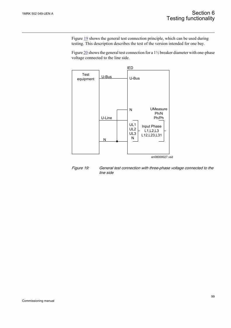
Figure 19 shows the general test connection principle, which can be used duringtesting. This description describes the test of the version intended for one bay.
Figure 20 shows the general test connection for a 1½ breaker diameter with one-phasevoltage connected to the line side.
Testequipment
UMeasurePh/NPh/Ph
en08000027.vsd
U-Bus
U-Line
N
IED
U-Bus
N
UL1UL2UL3
N
Input PhaseL1,L2,L3
L12,L23,L31
IEC08000027 V1 EN
Figure 19: General test connection with three-phase voltage connected to theline side
1MRK 502 049-UEN A Section 6Testing functionality
99Commissioning manual

U-Bus1
U-Line1
N
Testequipment
IED
U-Bus1
N
IEC11000273-2-en.vsd
N
UMeasure Ph/NPh/Ph
U-Bus2
U-Line2
U-Bus2
U-Line2
U-Line1
IEC11000273 V2 EN
Figure 20: General test connection for a 1½ breaker diameter with one-phasevoltage connected to the line side
6.9.1.1 Testing the synchronizing function
This section is applicable only if the synchronizing function is included.
The voltage inputs used are:
U-Line UL1, UL2 or UL3 line 1 voltage inputs on the IED
U-Bus Bus voltage input on the IED
Testing the frequency differenceThe frequency difference is in the example set at 0.20 Hz on the local HMI, and the testshould verify that operation is achieved when the FreqDiffMax frequency differenceis lower than 0.20 Hz. The test procedure below will depend on the settings used. InputSTARTSYN must be activated during the test.
1. Apply voltages1.1. U-Line = 100% GblBaseSelLine and f-Line = 50.0 Hz1.2. U-Bus = 100% GblBaseSelBus and f-Bus = 50.2Hz
2. Check that a closing pulse is submitted at a closing angle less than 2 degrees fromphase equality. Modern test sets will evaluate this automatically.
3. Repeat with
Section 6 1MRK 502 049-UEN ATesting functionality
100Commissioning manual
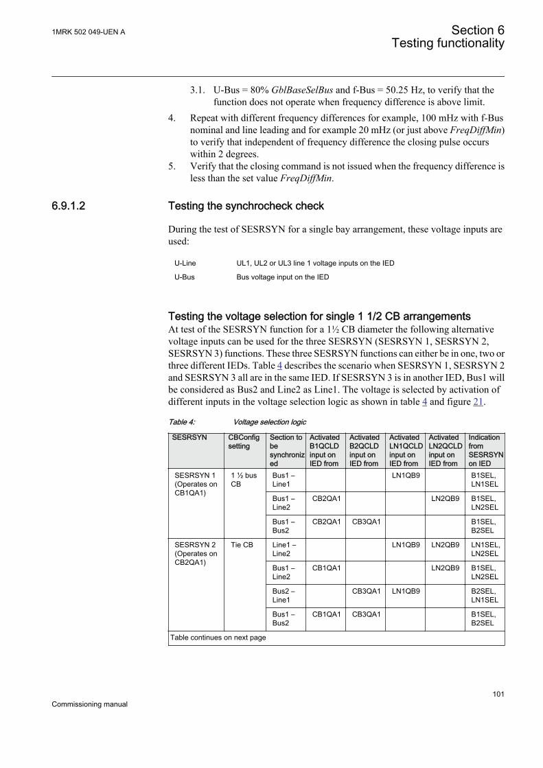
3.1. U-Bus = 80% GblBaseSelBus and f-Bus = 50.25 Hz, to verify that thefunction does not operate when frequency difference is above limit.
4. Repeat with different frequency differences for example, 100 mHz with f-Busnominal and line leading and for example 20 mHz (or just above FreqDiffMin)to verify that independent of frequency difference the closing pulse occurswithin 2 degrees.
5. Verify that the closing command is not issued when the frequency difference isless than the set value FreqDiffMin.
6.9.1.2 Testing the synchrocheck check
During the test of SESRSYN for a single bay arrangement, these voltage inputs areused:
U-Line UL1, UL2 or UL3 line 1 voltage inputs on the IED
U-Bus Bus voltage input on the IED
Testing the voltage selection for single 1 1/2 CB arrangementsAt test of the SESRSYN function for a 1½ CB diameter the following alternativevoltage inputs can be used for the three SESRSYN (SESRSYN 1, SESRSYN 2,SESRSYN 3) functions. These three SESRSYN functions can either be in one, two orthree different IEDs. Table 4 describes the scenario when SESRSYN 1, SESRSYN 2and SESRSYN 3 all are in the same IED. If SESRSYN 3 is in another IED, Bus1 willbe considered as Bus2 and Line2 as Line1. The voltage is selected by activation ofdifferent inputs in the voltage selection logic as shown in table 4 and figure 21.
Table 4: Voltage selection logic
SESRSYN CBConfigsetting
Section tobesynchronized
ActivatedB1QCLDinput onIED from
ActivatedB2QCLDinput onIED from
ActivatedLN1QCLDinput onIED from
ActivatedLN2QCLDinput onIED from
IndicationfromSESRSYNon IED
SESRSYN 1(Operates onCB1QA1)
1 ½ busCB
Bus1 –Line1
LN1QB9 B1SEL,LN1SEL
Bus1 –Line2
CB2QA1 LN2QB9 B1SEL,LN2SEL
Bus1 –Bus2
CB2QA1 CB3QA1 B1SEL,B2SEL
SESRSYN 2(Operates onCB2QA1)
Tie CB Line1 –Line2
LN1QB9 LN2QB9 LN1SEL,LN2SEL
Bus1 –Line2
CB1QA1 LN2QB9 B1SEL,LN2SEL
Bus2 –Line1
CB3QA1 LN1QB9 B2SEL,LN1SEL
Bus1 –Bus2
CB1QA1 CB3QA1 B1SEL,B2SEL
Table continues on next page
1MRK 502 049-UEN A Section 6Testing functionality
101Commissioning manual

SESRSYN CBConfigsetting
Section tobesynchronized
ActivatedB1QCLDinput onIED from
ActivatedB2QCLDinput onIED from
ActivatedLN1QCLDinput onIED from
ActivatedLN2QCLDinput onIED from
IndicationfromSESRSYNon IED
SESRSYN 3(Operates onCB3QA1)
1 ½ busalt. CB(mirrored)
Bus2 –Line2
LN2QB9 B2SEL,LN2SEL
Bus2 –Line1
CB2QA1 LN1QB9 B2SEL,LN1SEL
Bus2 –Bus1
CB2QA1 CB1QA1 B1SEL,B2SEL
Bus 1
Bus 2
CB1QA1 (SESRSYN 1)
CB3QA1 (SESRSYN 3)
CB2QA1 (SESRSYN 2)
Line 1 Line 2
LN1QB9 LN2QB9
IEC11000274-2-en.vsd
IEC11000274 V2 EN
Figure 21: Objects used in the voltage selection logic
Testing the voltage differenceSet the voltage difference to 0.15 p.u. on the local HMI, and the test should check thatoperation is achieved when the voltage difference UDiffSC is lower than 0.15 p.u.
The settings used in the test shall be final settings. The test shall be adapted to sitesetting values instead of values in the example below.
Test with no voltage difference between the inputs.
Test with a voltage difference higher than the set UDiffSC.
Section 6 1MRK 502 049-UEN ATesting functionality
102Commissioning manual

1. Apply voltages U-Line (for example) = 80% GblBaseSelLine and U-Bus = 80%GblBaseSelBus
2. Check that the AUTOSYOK and MANSYOK outputs are activated.3. The test can be repeated with different voltage values to verify that the function
operates within the set UDiffSC. Check with both U-Line and U-Busrespectively lower than the other.
4. Increase the U-Bus to 110% GblBaseSelBus, and the U-Line = 90%GblBaseSelLine and also the opposite condition.
5. Check that the two outputs for manual and auto synchronism are not activated.
Testing the phase angle differenceThe phase angle differences PhaseDiffM and PhaseDiffA respectively are set to theirfinal settings and the test should verify that operation is achieved when the phase angledifference is lower than this value both leading and lagging.
Test with no voltage difference.
1. Apply voltages U-Line (for example) = 100% GblBaseSelLine and U-Bus =100% GblBaseSelBus, with a phase difference equal to 0 degrees and afrequency difference lower than FreqDiffA and FreqDiffM.
2. Check that the AUTOSYOK and MANSYOK outputs are activated.The test can be repeated with other phase difference values to verify that thefunction operates for values lower than the set ones, PhaseDiffM andPhaseDiffA. By changing the phase angle on the voltage connected to U-Bus,between ± dφ degrees, the user can check that the two outputs are activated fora phase difference lower than the set value. It should not operate for other values.See figure 22.
+dj
-dj
U-Bus
U-Line operation
U-Bus
No operation
en05000551.vsd
IEC05000551 V1 EN
Figure 22: Test of phase difference
3. Change the phase angle between +dφ and -dφ and verify that the two outputs areactivated for phase differences between these values but not for phasedifferences outside, see figure 22.
1MRK 502 049-UEN A Section 6Testing functionality
103Commissioning manual

Testing the frequency differenceThe frequency difference test should verify that operation is achieved when theFreqDiffA and FreqDiffM frequency difference is lower than the set value for manualand auto synchronizing check, FreqDiffA and FreqDiffM respectively and thatoperation is blocked when the frequency difference is greater.
Test with frequency difference = 0 mHz
Test with a frequency difference outside the set limits for manual and autosynchronizing check respectively.
1. Apply voltages U-Line equal to 100% GblBaseSelLine and U-Bus equal to100% GblBaseSelBus, with a frequency difference equal to 0 mHz and a phasedifference lower than the set value.
2. Check that the AUTOSYOK and MANSYOK outputs are activated.3. Apply voltage to the U-Line equal to 100% GblBaseSelLine with a frequency
equal to 50 Hz and voltage U-Bus equal to 100% GblBaseSelBus, with afrequency outside the set limit.
4. Check that the two outputs are not activated. The test can be repeated withdifferent frequency values to verify that the function operates for values lowerthan the set ones. If a modern test set is used, the frequency can be changedcontinuously.
Testing the reference voltage
1. Use the same basic test connection as in figure 19.The voltage difference between the voltage connected to U-Bus and U-Lineshould be 0%, so that the AUTOSYOK and MANSYOK outputs are activatedfirst.
2. Change the U-Line voltage connection to U-Line2 without changing the settingon the local HMI. Check that the two outputs are not activated.
6.9.1.3 Testing the energizing check
During the test of the energizing check function for a single bay arrangement, thesevoltage inputs are used:
U-Line UL1, UL2 or UL3 line1 voltage inputs on the IED
U-Bus Bus voltage input on the IED
GeneralWhen testing the energizing check function for the applicable bus, arrangement shallbe done for the energizing check functions. The voltage is selected by activation ofdifferent inputs in the voltage selection logic.
Live voltage level is fixed to 80% UBase and dead voltage level to fixed 40% UBase.
Section 6 1MRK 502 049-UEN ATesting functionality
104Commissioning manual

The test shall be performed according to the settings for the station. Test thealternatives below that are applicable.
Testing the dead line live bus (DLLB)The test should verify that the energizing check function operates for a low voltage onthe U-Line and for a high voltage on the U-Bus. This corresponds to the energizing ofa dead line to a live bus.
1. Apply a single-phase voltage 100% GblBaseSelBus to the U-Bus, and a single-phase voltage 30% GblBaseSelLine to the U-Line.
2. Check that the AUTOENOK and MANENOK outputs are activated after settAutoEnerg respectively tManEnerg.
3. Increase the U-Line to 60% GblBaseSelLine and U-Bus to be equal to 100%GblBaseSelBus. The outputs should not be activated.
4. The test can be repeated with different values on the U-Bus and the U-Line.
Testing the dead bus live line (DBLL)The test should verify that the energizing check function operates for a low voltage onthe U-Bus and for a high voltage on the U-Line. This corresponds to an energizing ofa dead bus to a live line.
1. Verify the settings AutoEnerg or ManEnerg to be DBLL.2. Apply a single-phase voltage of 30% GblBaseSelBus to the U-Bus and a single-
phase voltage of 100% GblBaseSelLine to the U-Line.3. Check that the AUTOENOK and MANENOK outputs are activated after set
tAutoEnerg respectively tManEnerg.4. Decrease the U-Line to 60% GblBaseSelLine and keep the U-Bus equal to 30%
GblBaseSelBus. The outputs should not be activated.5. The test can be repeated with different values on the U-Bus and the U-Line.
Testing both directions (DLLB or DBLL)
1. Verify the local HMI settings AutoEnerg or ManEnerg to be Both.2. Apply a single-phase voltage of 30% GblBaseSelLine to the U-Line and a single-
phase voltage of 100% GblBaseSelBus to the U-Bus.3. Check that the AUTOENOK and MANENOK outputs are activated after set
tAutoEnerg respectively tManEnerg.4. Change the connection so that the U-Line is equal to100% GblBaseSelLine and
the U-Bus is equal to 30% GblBaseSelBus. The outputs should still be activated.5. The test can be repeated with different values on the U-Bus and the U-Line.
Testing the dead bus dead line (DBDL)The test should verify that the energizing check function operates for a low voltage onboth the U-Bus and the U-Line, that is, closing of the breaker in a non-energizedsystem. Test is valid only when this function is used.
1MRK 502 049-UEN A Section 6Testing functionality
105Commissioning manual

1. Verify the local HMI setting AutoEnerg to be Off and ManEnerg to be DBLL.2. Set the parameter ManEnergDBDL to On.3. Apply a single-phase voltage of 30% GblBaseSelBus to the U-Bus and a single-
phase voltage of 30% GblBaseSelLine to the U-Line.4. Check that the MANENOK output is activated after set tManEnerg.5. Increase the U-Bus to 80% GblBaseSelBus and keep the U-Line equal to 30%
GblBaseSelLine. The outputs should not be activated.6. Repeat the test with ManEnerg set to DLLB with different values on the U-Bus
and the U-Line voltage.
6.9.1.4 Testing the voltage selection
Testing the voltage selection for single CB arrangementsThis test should verify that the correct voltage is selected for the measurement in theSESRSYN function used in a double-bus arrangement. Apply a single-phase voltageof 30% GblBaseSelLine to the U-Line and a single-phase voltage of 100%GblBaseSelBus to the U-Bus.
If the UB1OK or UB2OK inputs for the fuse failure are used, they must be activated,during tests below. Also verify that deactivation prevents operation and gives analarm.
1. Connect the signals above to binary inputs and binary outputs.2. Connect the voltage inputs to the analog inputs used for each bus or line
depending of the type of busbar arrangement and verify that correct outputsignals are generated.
6.9.1.5 Completing the test
Continue to test another function or end the testing by setting the parameter TestModeto Off under Main menu/Tests/IED test mode/TESTMODE:1. If another functionis tested, then set the parameter Blocked to No under Main menu/Tests/Function testmodes/Control/SESRSYN(25,SYNC)/SESRSYN:X for the function, or for eachindividual function in a chain, to be tested next. Remember to set the parameterBlocked to Yes, for each individual function that has been tested.
6.9.2 Interlocking
Prepare the IED for verification of settings as outlined in 5.1 "Preparing the IED toverify settings".
Values of the logical signals are available on the local HMI under Main menu/Tests/Function status/Control/<Function>/<Function:1>. The Signal Monitoring inPCM600 shows the same signals that are available on the local HMI.
Section 6 1MRK 502 049-UEN ATesting functionality
106Commissioning manual

The interlocking function consists of a bay-level part and a station-level part. Theinterlocking is delivery specific and is realized by bay-to-bay communication over thestation bus. For that reason, test the function in a system, that is, either in a completedelivery system as an acceptance test (FAT/SAT) or as parts of that system.
6.9.3 Apparatus control APC
The apparatus control function consists of four types of function blocks, which areconnected in a delivery-specific way between bays and to the station level. For thatreason, test the total function in a system, that is, either in a complete delivery systemas an acceptance test (FAT/SAT) or as parts of that system.
If a block/unblock command is sent from remote to function, while theIED is shut down, this command will not be recognized after the startup, thus the command that was sent prior to the shut down is used. Insuch cases, where there is a mismatch, the user is advised to make acomplete cycle of block/unblock operations to align the statuses.
6.10 Testing logic functions
6.10.1 Tripping logic, common 3-phase output SMPPTRC
Prepare the IED for verification of settings as outlined in 5.1 "Preparing the IED toverify settings".
Values of the logical signals for SMPPTRC are available on the local HMI underMain menu/Tests/Function status/Logic/SMPPTRC(94,1->0)/SMPPTRC:X.The Signal Monitoring in PCM600 shows the same signals that are available on thelocal HMI.
This function is functionality tested together with other protection functions (earth-fault overcurrent protection, and so on) within the IED. It is recommended that thefunction is tested together with the autorecloser function, regardless of whether theautorecloser function is integrated or external.
6.10.1.1 Three-phase operating mode
1. Check that AutoLock and TripLockout are both set to Off.2. Initiate a three-phase fault.
An adequate time interval between the faults should be considered, to overcomea reclaim time caused by the possible activation of the Autorecloser function,SMBRREC. The function must issue a three-phase trip in all cases, when a trip
1MRK 502 049-UEN A Section 6Testing functionality
107Commissioning manual

is initiated by any protection function, either integrated or external. Thefunctional TRIP output signal must always appear.
6.10.1.2 Circuit breaker lockout
The following tests should be carried out when the built-in lockout function is used inaddition to possible other tests, which depends on the complete configuration of anIED.
1. Check that AutoLock and TripLockout are both set to Off.2. Initiate a three-phase fault.
The functional output TRIP should be active at each fault. The outputCLLKOUT must not be activated.
3. Activate the automatic lockout function, set AutoLock = On and repeat.Besides the TRIP outputs, CLLKOUT should be set.
4. Reset the lockout signal by activating the reset lockout (RSTLKOUT) signal.5. Activate the TRIP signal lockout function, set TripLockout = On and repeat.
The output TRIP must be active and stay active after each fault. CLLKOUT mustbe activated.
6. Reset the lockout.All functional outputs should reset.
7. Deactivate the TRIP signal lockout function, set TripLockout = Off and theautomatic lockout function, set AutoLock = Off if not used.
6.10.1.3 Completing the test
Continue to test another function or end the testing by setting the parameter TestModeto Off under Main menu/Tests/IED test mode/TESTMODE:1. If another functionis tested, then set the parameter Blocked to No under Main menu/Tests/Function testmodes/Logic/SMPPTRC(94,1->0)/SMPPTRC:X for the function, or for eachindividual function in a chain, to be tested next. Remember to set the parameterBlocked to Yes, for each individual function that has been tested.
6.11 Testing monitoring functions
6.11.1 Event counter CNTGGIO
The event counter function CNTGGIO can be tested by connecting a binary input tothe counter under test and applying pulses to the counter. The speed of pulses must notexceed 10 per second. Normally the counter will be tested in connection with tests onthe function that the counter is connected to, such as trip logic. When configured, testit together with the function that operates it. Trig the function and check that thecounter result corresponds with the number of operations.
Section 6 1MRK 502 049-UEN ATesting functionality
108Commissioning manual

6.11.2 Limit counter L4UFCNT
The Limit counter function L4UFCNT can be tested by connecting a binary input tothe counter and applying pulses to the counter. The speed of the pulses must notexceed the cycle time of the function. Normally the counter will be tested when testingthe function that the counter is connected to, such as the trip function. When thefunction is configured, test it together with the function that operates it. Trig thefunction and check that the counter result corresponds to the number of operations.
6.11.2.1 Completing the test
Continue to test another function or end the test by changing the Test mode setting toOff. Restore connections and settings to their original values, if they were changed fortesting purposes.
6.12 Testing metering functions
6.12.1 Pulse counter PCGGIO
The test of the Pulse counter function PCGGIO requires the Parameter Setting tool inPCM600 or an appropriate connection to the local HMI with the necessaryfunctionality. A known number of pulses with different frequencies are connected tothe pulse counter input. The test should be performed with settings Operation = On orOperation = Off and the function blocked or unblocked. The pulse counter value isthen checked in PCM600 or on the local HMI.
6.13 Testing station communication
6.13.1 Establishing connection and verifying the IEC 61850communication
About this chapterThis chapter contains instructions on how to establish connection and verify that theIEC 61850 communication operates as intended, when the IED is connected to anEthernet network via the optical ports of the COM module.
6.13.1.1 Overview
The COM03 ports are used for substation bus (IEC 61850-8-1) communication aswell as redundant communication.
The COM05 ports are also used for communication but not redundantcommunication.
1MRK 502 049-UEN A Section 6Testing functionality
109Commissioning manual

For IEC 61850-8-1 redundant communication according to IEC62439–3 Edition 2,port LAN_1A and LAN_1B is utilized.
Redundant communication according to IEC62439–3 Edition 1 andIEC 61850–9–2LE process bus communication are not supported inthe 650 Ver 1.3 series IEDs.
6.13.1.2 Setting the station communication
To enable the IEC 61850 communication, the corresponding COM03 ports must beactivated. Port LAN1 A and LAN1 B are used for redundancy.
If COM03 is used; the following below apply. If COM05 is used; there is noredundancy and the port is named LAN1 or (FRONT)
To enable IEC 61850 station communication:
• The IEC 61850-8-1 station communication functionality must be configured inthe local HMI. Navigate to Main Menu/Configuration/Communication/TCP-IP configuation/ETHLAN1_AB and set the OperationMode parameter toNonRedundant(A) or, for redundant communication, to PRP(A+B).
• To enable GOOSE communication, the Operation parameter for thecorresponding GOOSE function blocks (GOOSEBINRCV andGOOSEINTLKRCV) must be set to On in the application configuration.
• To enable GOOSE communication via the front port the parameter GOOSE inMain menu/Configuration/Communication/Station communication/IEC61850-8-1/PortSelGOOSE must be set to Front. To enable GOOSEcommunication via rear port the parameter PortSelGOOSE must be set to LAN1.
To enable IEC 61850 station communication:
1. Enable IEC 61850-8-1 (substation bus) communication for port A and B.1.1. Set values for ETHLAN1_AB.
Navigate to Main Menu/Configuration/TCP-IP configuation/ETHLAN1_AB.Set values for OperationMode, IPAddress and IPMask. OperationModemust be set to NonRedundantA.Check that the correct IP address is assigned to the port.
1.2. Enable IEC 61850-8-1 communication.Navigate to Main menu/Settings/General settings/Communication/Station communication/IEC 61850-8-1.Set Operation to On and PortSelGOOSE to the port used.
2. Enable redundant IEC 61850-8-1 communication for port A and B.2.1. Enable redundant communication.
Section 6 1MRK 502 049-UEN ATesting functionality
110Commissioning manual

Navigate to Main Menu/Configuration/TCP-IP configuation/ETHLAN1_AB.Set values for OperationMode, IPAddress and IPMask. OperationModemust be set to PRP(A+B).
Make sure that the optical fibres are connected correctly.
6.13.1.3 Verifying the station communication
Connect a PC to the substation network and ping the connected IED and the SubstationMaster PC to verify that the communication is working up to the transport layer.
The best way to verify the communication up to the application layer is to use aprotocol analyzer connected to the substation or process bus and monitor thecommunication.
Verifying redundant IEC 61850-8-1 communicationEnsure that the IED receives IEC 61850-8-1 data on both ports A and B. In the localHMI navigate to Main menu/Tests/Function status/Communication/PRP Status/LAN1–A / LAN1–B and check that both signals LAN1-A and LAN1-B are shown asOk. Remove the optical connection to one of the ports A or B. Verify that either signalLAN1-A or LAN1-B (depending on which connection that was removed) are shownas Error and that the other signal is shown as Ok. Be sure to re-connect the removedconnection after completed verification.
6.14 Exit test mode
The following procedure is used to return to normal operation.
1. Navigate to the test mode folder.2. Change the On setting to Off. Press the 'E' key and the left arrow key.3. Answer YES, press the 'E' key and exit the menus.
1MRK 502 049-UEN A Section 6Testing functionality
111Commissioning manual

112
Section 7 Commissioning and maintenance of thefault clearing system
7.1 Commissioning and maintenance of the fault clearingsystem
About this chapterThis chapter discusses maintenance tests and other periodic maintenance measures.
7.1.1 Commissioning tests
During commissioning all protection functions shall be verified with the settingvalues used at each plant. The commissioning tests must include verification of allcircuits by green-lining the circuit diagrams and the configuration diagrams for theused functions.
Further, the settings for protection functions are tested and recorded carefully asoutlined for the future periodic maintenance tests.
The final testing includes primary verification of all directional functions where loadcurrents is checked on the local HMI and in PCM600. The amplitudes and angles ofall currents and voltages should be checked and the symmetry verified.
Directional functions have information about the measured direction and, forexample, measured impedance. These values must be checked and verified as correctwith the export or import of power available.
Finally, final trip tests must be performed. This involves activation of protectionfunctions or tripping outputs with the circuit breaker closed and the tripping of thebreaker verified. When several breakers are involved, each breaker must be checkedindividually and it must be verified that the other involved breakers are not tripped atthe same time.
7.1.2 Periodic maintenance tests
The periodicity of all tests depends on several factors, for example the importance ofthe installation, environmental conditions, simple or complex equipment, static orelectromechanical IEDs, and so on.
The normal maintenance praxis of the user should be followed. However, ABB'srecommendation is as follows:
1MRK 502 049-UEN A Section 7Commissioning and maintenance of the fault clearing system
113Commissioning manual
Every second to third year
• Visual inspection of all equipment.• Removal of dust on ventilation louvres and IEDs if necessary.• Periodic maintenance test for protection IEDs of object where no redundant
protections are provided.
Every four to six years
• Periodic maintenance test for protection IEDs of objects with redundantprotection system.
First maintenance test should always be carried out after the first halfyear of service.
When protection IEDs are combined with built-in control, the testinterval can be increased drastically, up to for instance 15 years,because the IED continuously reads service values, operates thebreakers, and so on.
7.1.2.1 Visual inspection
Prior to testing, the protection IEDs should be inspected to detect any visible damagethat may have occurred (for example, dirt or moisture deposits, overheating). Shouldburned contacts be observed when inspecting the IEDs, a diamond file or an extremelyfine file can be used to polish the contacts. Emery cloth or similar products must notbe used as insulating grains of abrasive may be deposited on the contact surfaces andcause failure.
Make sure that all IEDs are equipped with covers.
7.1.2.2 Maintenance tests
To be made after the first half year of service, then with the cycle as proposed aboveand after any suspected maloperation or change of the IED setting.
Testing of protection IEDs shall preferably be made with the primary circuit de-energized. The IED cannot protect the circuit during testing. Trained personnel maytest one IED at a time on live circuits where redundant protection is installed and de-energization of the primary circuit is not allowed.
ABB protection IEDs are preferably tested by aid of components from theCOMBITEST testing system described in information B03-9510 E. Maincomponents are RTXP 8/18/24 test switch located to the left in each protection IEDand RTXH 8/18/24 test handle, which is inserted in test switch at secondary testing.
Section 7 1MRK 502 049-UEN ACommissioning and maintenance of the fault clearing system
114Commissioning manual

All necessary operations such as opening of trip circuits, short-circuiting of currentcircuits and opening of voltage circuits are automatically performed in the right orderto allow for simple and safe secondary testing even with the object in service.
PreparationBefore starting maintenance testing, the test engineers should scrutinize applicablecircuit diagrams and have the following documentation available:
• Test instructions for protection IEDs to be tested• Test records from previous commissioning and maintenance tests• List of valid settings• Blank test records to fill in measured values
RecordingIt is of utmost importance to carefully record the test results. Special test sheetscovering the frequency of test, date of test and achieved test values should be used.IED setting list and protocols from previous tests should be available and all resultsshould be compared for differences. At component failures, spare equipment is usedand set to the requested value. A note of the exchange is made and the new measuredvalues are recorded. Test records for several years of testing should be stored in acommon file for a station, or a part of a station, to give a simple overview of the periodof testing and achieved test values. These test records are valuable when analysis ofservice disturbances shall be done.
Secondary injectionThe periodic maintenance test is done by secondary injection from a portable test set.Each protection shall be tested according to the secondary injection test informationfor the specific protection IED. Only the setting values adopted shall be checked foreach protection function. If the discrepancy between obtained value and requested setvalue is too big the setting should be adjusted, the new value recorded and a noteshould be made in the test record.
Alarm testWhen inserting the test handle the alarm and event signalling is normally blocked.This is done in the IED by setting the event reporting to Off during the test. This canbe done when the test handle is inserted or the IED is set to test mode from the localHMI. At the end of the secondary injection test it should be checked that the event andalarm signalling is correct by activating the events and performing some selected tests.
Self supervision checkOnce secondary testing has been completed, it should be checked that no self-supervision signals are activated continuously or sporadically. Especially check thetime synchronization system, GPS or other, and communication signals, both stationcommunication and remote communication.
Trip circuit checkWhen the protection IED undergoes an operational check, a tripping pulse is normallyobtained on one or more of the output contacts and preferably on the test switch. The
1MRK 502 049-UEN A Section 7Commissioning and maintenance of the fault clearing system
115Commissioning manual

healthy circuit is of utmost importance for the protection operation. If the circuit is notprovided with a continuous trip-circuit supervision, it is possible to check that circuitis really closed when the test-plug handle has been removed by using a high-ohmicvoltmeter and measuring between the plus and the trip output on the panel. Themeasurement is then done through the tripping magnet of the circuit breaker andtherefore the complete tripping circuit is checked.
Note that the breaker must be closed.
Please observe that the test system does not provide built-in securityduring this test. If the instrument should be set on Amp instead ofVolts, the circuit breaker naturally is tripped, therefore, great care isnecessary.
Trip circuit from trip IEDs to circuit breaker is often supervised by trip-circuitsupervision. It can then be checked that a circuit is healthy by opening tripping outputterminals in the cubicle. When the terminal is opened, an alarm shall be achieved onthe signal system after a delay of some seconds.
Remember to close the circuit directly after the test and tighten theterminal carefully.
Measurement of service currentsAfter a maintenance test it is recommended to measure the service currents and servicevoltages recorded by the protection IED. The service values are checked on the localHMI or in PCM600. Ensure that the correct values and angles between voltages andcurrents are recorded. Also check the direction of directional functions such asDistance and directional overcurrent functions.
For transformer differential protection, the achieved differential current value isdependent on the tap changer position and can vary between less than 1% up toperhaps 10% of rated current. For line differential functions, the capacitive chargingcurrents can normally be recorded as a differential current.
The zero-sequence current to earth-fault protection IEDs should be measured. Thecurrent amounts normally very small but normally it is possible to see if the currentcircuit is "alive".
The neutral-point voltage to an earth-fault protection IED is checked. The voltage isnormally 0.1 to 1V secondary. However, voltage can be considerably higher due toharmonics. Normally a CVT secondary can have around 2.5 - 3% third-harmonicvoltage.
Section 7 1MRK 502 049-UEN ACommissioning and maintenance of the fault clearing system
116Commissioning manual

RestoringMaintenance is very important to improve the availability of the protection system bydetecting failures before the protection is required to operate. There is however littlepoint in testing healthy equipment and then putting it back into service with an openterminal, with a removed fuse or open miniature circuit breaker with an openconnection, wrong setting, and so on.
Thus a list should be prepared of all items disturbed during test so that all can be putback into service quickly and without overlooking something. It should be put backinto service item by item and signed by the responsible engineer.
1MRK 502 049-UEN A Section 7Commissioning and maintenance of the fault clearing system
117Commissioning manual

118
Section 8 Troubleshooting
8.1 Fault tracing
8.1.1 Identifying hardware errors
1. Check the module with an error.• Check the general IED status in Main menu/Diagnostics/IED status/
General for a faulty hardware module.• Check the history of changes in internal event list in Main menu/
Diagnostics/Internal Events.2. Inspect the IED visually.
• Inspect the IED visually to find any physical error causes.• If you can find some obvious physical damage, contact ABB for repair or
replacement actions.3. Check whether the error is external or internal.
• Check that the error is not caused by external origins.• Remove the wiring from the IED and test the input and output operation
with an external test device.• If the problem remains, contact ABB for repair or replacement actions.
8.1.2 Identifying runtime errors
1. Check the error origin from IED's internal event list Main menu/Diagnostics/IED status/General.
2. Reboot the IED and recheck the supervision events to see if the fault hascleared.
3. In case of persistent faults, contact ABB for corrective actions.
8.1.3 Identifying communication errors
Communication errors are normally communication interruptions or synchronizationmessage errors due to communication link breakdown.
• Check the IEC61850 and DNP3 communication status in internal event list inMain menu/Diagnostics/IED Status/General.
• In case of persistent faults originating from IED's internal faults such ascomponent breakdown, contact ABB for repair or replacement actions.
1MRK 502 049-UEN A Section 8Troubleshooting
119Commissioning manual
8.1.3.1 Checking the communication link operation
There are several different communication links on the product. First check that allcommunication ports that are used for communication are turned on.
1. Check the front communication port RJ-45.1.1. Check that the uplink LED is lit with a steady green light.
The uplink LED is located on the LHMI above the RJ-45 communicationport on the left. The port is used for direct electrical communication to a PCconnected via a crossed-over Ethernet cable.
1.2. Check the communication status of the front port via the LHMI in Mainmenu/Test/Function status/Communication/DOSFRNT:1/Outputs.Check that the LINKUP value is 1, that is, the communication is working.When the value is 0, there is no communication link.
2. Check the communication status of the rear port X1 via the LHMI in Mainmenu/Tests/Function status/Communication/DOSLAN1:1/Outputs.The X1 communication port on the rear side of the IED is for optical Ethernet viaLC connector.• Check that the LINKUP value is 1, that is, the communication is working.
When the value is 0, there is no communication link.
8.1.3.2 Checking the time synchronization
• Select Main menu/Diagnostics/IED status/General and check the status of thetime synchronization on Time Synch.The Time synch value is Ready when the synchronization is in order.
Note that the time synchronization source has to be activated.Otherwise the value is always Ready.
8.1.4 Running the display test
To run the display test, either use the push buttons or start the test via the menu.
• Select Main menu/Tests/LED test.• Press or simultaneously and .
All the LEDs are tested by turning them on simultaneously. The display shows aset of patterns so that all the pixels are activated. After the test, the display returnsto normal state.
Section 8 1MRK 502 049-UEN ATroubleshooting
120Commissioning manual
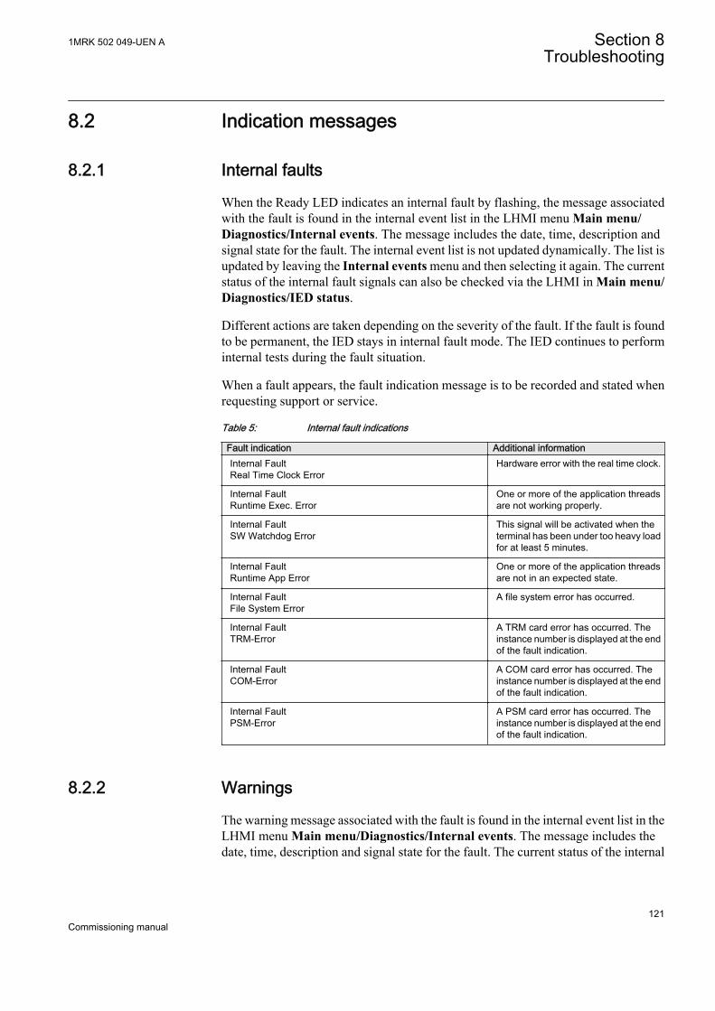
8.2 Indication messages
8.2.1 Internal faults
When the Ready LED indicates an internal fault by flashing, the message associatedwith the fault is found in the internal event list in the LHMI menu Main menu/Diagnostics/Internal events. The message includes the date, time, description andsignal state for the fault. The internal event list is not updated dynamically. The list isupdated by leaving the Internal events menu and then selecting it again. The currentstatus of the internal fault signals can also be checked via the LHMI in Main menu/Diagnostics/IED status.
Different actions are taken depending on the severity of the fault. If the fault is foundto be permanent, the IED stays in internal fault mode. The IED continues to performinternal tests during the fault situation.
When a fault appears, the fault indication message is to be recorded and stated whenrequesting support or service.
Table 5: Internal fault indications
Fault indication Additional informationInternal FaultReal Time Clock Error
Hardware error with the real time clock.
Internal FaultRuntime Exec. Error
One or more of the application threadsare not working properly.
Internal FaultSW Watchdog Error
This signal will be activated when theterminal has been under too heavy loadfor at least 5 minutes.
Internal FaultRuntime App Error
One or more of the application threadsare not in an expected state.
Internal FaultFile System Error
A file system error has occurred.
Internal FaultTRM-Error
A TRM card error has occurred. Theinstance number is displayed at the endof the fault indication.
Internal FaultCOM-Error
A COM card error has occurred. Theinstance number is displayed at the endof the fault indication.
Internal FaultPSM-Error
A PSM card error has occurred. Theinstance number is displayed at the endof the fault indication.
8.2.2 Warnings
The warning message associated with the fault is found in the internal event list in theLHMI menu Main menu/Diagnostics/Internal events. The message includes thedate, time, description and signal state for the fault. The current status of the internal
1MRK 502 049-UEN A Section 8Troubleshooting
121Commissioning manual

fault signals can also be checked via the LHMI in Main menu/Diagnostics/IEDstatus/General.
When a fault appears, record the fault indication message and state it when orderingservice.
Table 6: Warning indications
Warning indication Additional informationWarningIEC 61850 Error
IEC 61850 has not succeededin some actions such asreading the configuration file,startup etc.
WarningDNP3 Error
Error in DNP3 communication.
8.2.3 Additional indications
The additional indication messages do not activate internal fault or warning.
The messages are listed in the LHMI menu under the event list. The signal status datais found under the IED status and in the internal event list.
Table 7: Additional indications
Warning indication Additional informationTime Synch Error Source of the time synchronization is lost or time
system has made a time reset.
Settings Changed Settings have been changed.
Setting Groups Changed Setting group has been changed.
8.3 Correction procedures
8.3.1 Changing and setting the password
The password can only be set with PCM600.
For more information, see PCM600 documentation.
8.3.2 Identifying IED application problems
Navigate to the appropriate menu in the LHMI to identify possible problems.
• Check that the function is on.• Check that the correct setting group (1 to 4) is activated.• Check the blocking.
Section 8 1MRK 502 049-UEN ATroubleshooting
122Commissioning manual
• Check the mode.• Check the measurement value.• Check the connection to trip and disturbance recorder functions.• Check the channel settings.
8.3.2.1 Inspecting the wiring
The physical inspection of wiring connections often reveals the wrong connection forphase currents or voltages. However, even though the phase current or voltageconnections to IED terminals might be correct, wrong polarity of one or moremeasurement transformers can cause problems.
• Check the current or voltage measurements and their phase information fromMain menu/Measurements/Analog primary values or Analog secondaryvalues.
• Check that the phase information and phase shift between phases is correct.• Correct the wiring if needed.
• Change the parameter Negation in Configuration/Analog modules/3PhaseAnalogGroup/SMAI_20_n:1 (n= the number of the SMAIused).
Changing the Negation parameter is not recommendedwithout special skills.
• In PCM600, change the parameter CTStarPointn (n= the number on thecurrent input) under the parameter settings for each current input.
• Check the actual state of the connected binary inputs.• In LHMI, select Main menu/Tests/I/O modules. Then navigate to the
board with the actual binary input to be checked.• With PCM600, right-click the product and select Signal Monitoring. Then
navigate to the actual I/O board and to the binary input in question. Theactivated input signal is indicated with a yellow-lit diode.
• Measure output contacts using the voltage drop method of applying at least theminimum contact load given for the output relays in the technical data, forexample 100 mA at 24 V AC/DC.
Output relays, especially power output relays, are designed forbreaking high currents. Due to this, layers of high resistance mayappear on the surface of the contacts. Do not determine properfunctionality of connectivity or contact resistance by measuringwith a regular hand-held ohm meter.
1MRK 502 049-UEN A Section 8Troubleshooting
123Commissioning manual

A1
2
3
4
V
GUID-BBAEAF55-8D01-4711-A71D-BBC76B60BA3D V1 EN
Figure 23: Testing output contacts using the voltage drop method
1 Contact current
2 Contact voltage drop
3 Load
4 Supply voltage
Section 8 1MRK 502 049-UEN ATroubleshooting
124Commissioning manual

V1
2
A
GUID-31DF5495-91F1-4A4B-8FD5-50625038961E V1 EN
Figure 24: Testing a trip contact
1 Trip contact under test
2 Current limiting resistor
• To check the status of the output circuits driving the output relay via the LHMI,select Main menu/Tests/I/O modules and then navigate to the board with theactual binary output to be checked.
• Test and change the relay state manually.1. To set the IED to test mode, select Main menu/Tests/IED test mode/
TESTMODE:1 and set the parameter to On.2. To operate or force the output relay to operate, select and then navigate to
the board with the actual binary output relay to be operated/forced.3. Select the BOn_PO to be operated/forced and use and or to
operate the actual output relay.In PCM600, only the result of these operations can be checked by right-clicking the product and selecting Signal Monitoring tool and thennavigating to the actual I/O-board and the binary input in question. The
1MRK 502 049-UEN A Section 8Troubleshooting
125Commissioning manual

activated output signal is indicated with a yellow-lit diode. Each BOn_POis represented by two signals. The first signal in LHMI is the actual value1 or 0 of the output, and in PCM600 a lit or dimmed diode. The secondsignal is the status Normal or Forced. Forced status is only achieved whenthe BO is set to Forced or operated on the LHMI.
Set the parameter TestMode to Off after completing thesetests. The Start LED stops flashing when the relay is nolonger in test mode.
An initially high contact resistance does not cause problems as it is reduced quickly bythe electrical cleaning effect of fritting and thermal destruction of layers, bringing thecontact resistance back to the mOhm range. As a result, practically the full voltage isavailable at the load.
Section 8 1MRK 502 049-UEN ATroubleshooting
126Commissioning manual

Section 9 Glossary
AC Alternating current
ACC Actual channel
ACT Application configuration tool within PCM600
A/D converter Analog-to-digital converter
ADBS Amplitude deadband supervision
AI Analog input
ANSI American National Standards Institute
AR Autoreclosing
ASCT Auxiliary summation current transformer
ASD Adaptive signal detection
ASDU Application service data unit
AWG American Wire Gauge standard
BBP Busbar protection
BFOC/2,5 Bayonet fibre optic connector
BFP Breaker failure protection
BI Binary input
BOS Binary outputs status
BR External bistable relay
BS British Standards
CB Circuit breaker
CCITT Consultative Committee for International Telegraph andTelephony. A United Nations-sponsored standards bodywithin the International Telecommunications Union.
CCVT Capacitive Coupled Voltage Transformer
Class C Protection Current Transformer class as per IEEE/ ANSI
CMPPS Combined megapulses per second
CMT Communication Management tool in PCM600
CO cycle Close-open cycle
COMTRADE Standard format according to IEC 60255-24
COT Cause of transmission
CPU Central processing unit
1MRK 502 049-UEN A Section 9Glossary
127Commissioning manual

CR Carrier receive
CRC Cyclic redundancy check
CROB Control relay output block
CS Carrier send
CT Current transformer
CU Communication unit
CVT Capacitive voltage transformer
DAR Delayed autoreclosing
DARPA Defense Advanced Research Projects Agency (The USdeveloper of the TCP/IP protocol etc.)
DBDL Dead bus dead line
DBLL Dead bus live line
DC Direct current
DFC Data flow control
DFT Discrete Fourier transform
DHCP Dynamic Host Configuration Protocol
DI Digital input
DLLB Dead line live bus
DNP Distributed Network Protocol as per IEEE Std 1815-2012
DR Disturbance recorder
DRAM Dynamic random access memory
DRH Disturbance report handler
DTT Direct transfer trip scheme
EHV network Extra high voltage network
EIA Electronic Industries Association
EMC Electromagnetic compatibility
EMF Electromotive force
EMI Electromagnetic interference
EnFP End fault protection
EPA Enhanced performance architecture
ESD Electrostatic discharge
F-SMA Type of optical fibre connector
FAN Fault number
FCB Flow control bit; Frame count bit
Section 9 1MRK 502 049-UEN AGlossary
128Commissioning manual

FOX 20 Modular 20 channel telecommunication system for speech,data and protection signals
FOX 512/515 Access multiplexer
FOX 6Plus Compact time-division multiplexer for the transmission ofup to seven duplex channels of digital data over opticalfibers
FTP File Transfer Protocal
FUN Function type
GCM Communication interface module with carrier of GPSreceiver module
GDE Graphical display editor within PCM600
GI General interrogation command
GIS Gas-insulated switchgear
GOOSE Generic object-oriented substation event
GPS Global positioning system
GSAL Generic security application
GSE Generic substation event
HDLC protocol High-level data link control, protocol based on the HDLCstandard
HFBR connector type Plastic fiber connector
HMI Human-machine interface
HSAR High speed autoreclosing
HV High-voltage
HVDC High-voltage direct current
IDBS Integrating deadband supervision
IEC International Electrical Committee
IEC 61869-2 IEC Standard, Instrument transformers
IEC 60870-5-103 Communication standard for protective equipment. A serialmaster/slave protocol for point-to-point communication
IEC 61850 Substation automation communication standard
IEC 61850–8–1 Communication protocol standard
IEEE Institute of Electrical and Electronics Engineers
IEEE 802.12 A network technology standard that provides 100 Mbits/s ontwisted-pair or optical fiber cable
IEEE P1386.1 PCI Mezzanine Card (PMC) standard for local bus modules.References the CMC (IEEE P1386, also known as CommonMezzanine Card) standard for the mechanics and the PCI
1MRK 502 049-UEN A Section 9Glossary
129Commissioning manual

specifications from the PCI SIG (Special Interest Group) forthe electrical EMF (Electromotive force).
IEEE 1686 Standard for Substation Intelligent Electronic Devices(IEDs) Cyber Security Capabilities
IED Intelligent electronic device
I-GIS Intelligent gas-insulated switchgear
Instance When several occurrences of the same function are availablein the IED, they are referred to as instances of that function.One instance of a function is identical to another of the samekind but has a different number in the IED user interfaces.The word "instance" is sometimes defined as an item ofinformation that is representative of a type. In the same wayan instance of a function in the IED is representative of atype of function.
IP 1. Internet protocol. The network layer for the TCP/IPprotocol suite widely used on Ethernet networks. IP is aconnectionless, best-effort packet-switching protocol. Itprovides packet routing, fragmentation and reassemblythrough the data link layer.2. Ingression protection, according to IEC standard
IP 20 Ingression protection, according to IEC standard, level 20
IP 40 Ingression protection, according to IEC standard, level 40
IP 54 Ingression protection, according to IEC standard, level 54
IRF Internal failure signal
IRIG-B: InterRange Instrumentation Group Time code format B,standard 200
ITU International Telecommunications Union
LAN Local area network
LCD Liquid crystal display
LDD Local detection device
LED Light-emitting diode
LNT LON network tool
MCB Miniature circuit breaker
MVAL Value of measurement
NCC National Control Centre
NOF Number of grid faults
NUM Numerical module
OCO cycle Open-close-open cycle
OCP Overcurrent protection
Section 9 1MRK 502 049-UEN AGlossary
130Commissioning manual

OLTC On-load tap changer
OTEV Disturbance data recording initiated by other event thanstart/pick-up
OV Over-voltage
Overreach A term used to describe how the relay behaves during a faultcondition. For example, a distance relay is overreachingwhen the impedance presented to it is smaller than theapparent impedance to the fault applied to the balance point,that is, the set reach. The relay “sees” the fault but perhaps itshould not have seen it.
PCI Peripheral component interconnect, a local data bus
PCM600 Protection and control IED manager
PC-MIP Mezzanine card standard
POR Permissive overreach
POTT Permissive overreach transfer trip
Process bus Bus or LAN used at the process level, that is, in nearproximity to the measured and/or controlled components
PSM Power supply module
PST Parameter setting tool within PCM600
PT ratio Potential transformer or voltage transformer ratio
PUTT Permissive underreach transfer trip
RCA Relay characteristic angle
RISC Reduced instruction set computer
RMS value Root mean square value
RS422 A balanced serial interface for the transmission of digitaldata in point-to-point connections
RS485 Serial link according to EIA standard RS485
RTC Real-time clock
RTU Remote terminal unit
SA Substation Automation
SBO Select-before-operate
SC Switch or push button to close
SCL Short circuit location
SCS Station control system
SCADA Supervision, control and data acquisition
SCT System configuration tool according to standard IEC 61850
SDU Service data unit
1MRK 502 049-UEN A Section 9Glossary
131Commissioning manual

SMA connector Subminiature version A, A threaded connector withconstant impedance.
SMT Signal matrix tool within PCM600
SMS Station monitoring system
SNTP Simple network time protocol – is used to synchronizecomputer clocks on local area networks. This reduces therequirement to have accurate hardware clocks in everyembedded system in a network. Each embedded node caninstead synchronize with a remote clock, providing therequired accuracy.
SOF Status of fault
SPA Strömberg protection acquisition, a serial master/slaveprotocol for point-to-point communication
SRY Switch for CB ready condition
ST Switch or push button to trip
Starpoint Neutral point of transformer or generator
SVC Static VAr compensation
TC Trip coil
TCS Trip circuit supervision
TCP Transmission control protocol. The most common transportlayer protocol used on Ethernet and the Internet.
TCP/IP Transmission control protocol over Internet Protocol. Thede facto standard Ethernet protocols incorporated into4.2BSD Unix. TCP/IP was developed by DARPA forInternet working and encompasses both network layer andtransport layer protocols. While TCP and IP specify twoprotocols at specific protocol layers, TCP/IP is often used torefer to the entire US Department of Defense protocol suitebased upon these, including Telnet, FTP, UDP and RDP.
TEF Time delayed earth-fault protection function
TLS Transport Layer Security
TM Transmit (disturbance data)
TNC connector Threaded Neill-Concelman, a threaded constant impedanceversion of a BNC connector
TP Trip (recorded fault)
TPZ, TPY, TPX, TPS Current transformer class according to IEC
TRM Transformer Module. This module transforms currents andvoltages taken from the process into levels suitable forfurther signal processing.
TYP Type identification
Section 9 1MRK 502 049-UEN AGlossary
132Commissioning manual

UMT User management tool
Underreach A term used to describe how the relay behaves during a faultcondition. For example, a distance relay is underreachingwhen the impedance presented to it is greater than theapparent impedance to the fault applied to the balance point,that is, the set reach. The relay does not “see” the fault butperhaps it should have seen it. See also Overreach.
UTC Coordinated Universal Time. A coordinated time scale,maintained by the Bureau International des Poids et Mesures(BIPM), which forms the basis of a coordinateddissemination of standard frequencies and time signals.UTC is derived from International Atomic Time (TAI) bythe addition of a whole number of "leap seconds" tosynchronize it with Universal Time 1 (UT1), thus allowingfor the eccentricity of the Earth's orbit, the rotational axis tilt(23.5 degrees), but still showing the Earth's irregularrotation, on which UT1 is based. The Coordinated UniversalTime is expressed using a 24-hour clock, and uses theGregorian calendar. It is used for aeroplane and shipnavigation, where it is also sometimes known by the militaryname, "Zulu time." "Zulu" in the phonetic alphabet standsfor "Z", which stands for longitude zero.
UV Undervoltage
WEI Weak end infeed logic
VT Voltage transformer
3IO Three times zero-sequence current. Often referred to as theresidual or the earth-fault current
3UO Three times the zero sequence voltage. Often referred to asthe residual voltage or the neutral point voltage
1MRK 502 049-UEN A Section 9Glossary
133Commissioning manual

134

135

Contact us
For more information please contact:
ABB ABGrid Automation ProductsSE-721 59 Västerås, SwedenPhone +46 (0) 21 32 50 00
www.abb.com/protection-control
Note:We reserve the right to make technical changes or modifythe contents of this document without prior notice. ABB ABdoes not accept any responsibility whatsoever for potentialerrors or possible lack of information in this document.We reserve all rights in this document and in the subjectmatter and illustrations contained herein. Any reproduction,disclosure to third parties or utilization of its contents – inwhole or in part – is forbidden without prior written consent ofABB AB.
© Copyright 2013 ABB.
All rights reserved.
Scan this QR code to visit our website
1MR
K 5
02 0
49-U
EN