generator set specification sheet format · the qsk23 is an in-line 6 cylinder engine with a...
TRANSCRIPT
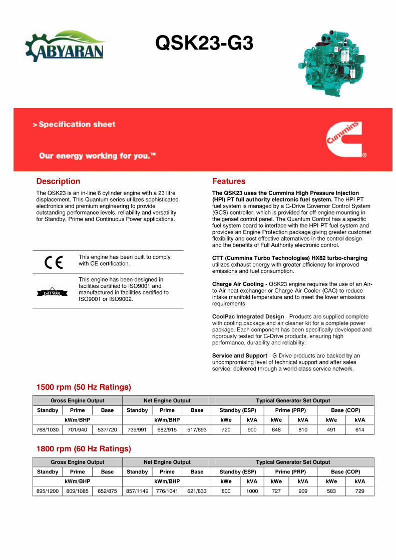
QSK23-G3
Description The QSK23 is an in-line 6 cylinder engine with a 23 litre displacement. This Quantum series utilizes sophisticated electronics and premium engineering to provide outstanding performance levels, reliability and versatility for Standby, Prime and Continuous Power applications.
Features The QSK23 uses the Cummins High Pressure Injection (HPI) PT full authority electronic fuel system. The HPI PT fuel system is managed by a G-Drive Governor Control System (GCS) controller, which is provided for off-engine mounting in the genset control panel. The Quantum Control has a specific fuel system board to interface with the HPI-PT fuel system and provides an Engine Protection package giving greater customer flexibility and cost effective alternatives in the control design and the benefits of Full Authority electronic control.
CTT (Cummins Turbo Technologies) HX82 turbo-charging utilizes exhaust energy with greater efficiency for improved emissions and fuel consumption.
Charge Air Cooling - QSK23 engine requires the use of an Air-to-Air heat exchanger or Charge-Air-Cooler (CAC) to reduce intake manifold temperature and to meet the lower emissions requirements.
CoolPac Integrated Design - Products are supplied complete with cooling package and air cleaner kit for a complete power package. Each component has been specifically developed and rigorously tested for G-Drive products, ensuring high performance, durability and reliability.
Service and Support - G-Drive products are backed by an uncompromising level of technical support and after sales service, delivered through a world class service network.
This engine has been built to comply with CE certification.
This engine has been designed in facilities certified to ISO9001 and manufactured in facilities certified to ISO9001 or ISO9002.
1500 rpm (50 Hz Ratings)
Gross Engine Output Net Engine Output Typical Generator Set Output
Standby Prime Base Standby Prime Base Standby (ESP) Prime (PRP) Base (COP)
kWm/BHP kWm/BHP kWe kVA kWe kVA kWe kVA
768/1030 701/940 537/720 739/991 682/915 517/693 720 900 648 810 491 614
1800 rpm (60 Hz Ratings)
Gross Engine Output Net Engine Output Typical Generator Set Output
Standby Prime Base Standby Prime Base Standby (ESP) Prime (PRP) Base (COP)
kWm/BHP kWm/BHP kWe kVA kWe kVA kWe kVA
895/1200 809/1085 652/875 857/1149 776/1041 621/833 800 1000 727 909 583 729

General Engine Data Ratings Definitions
Type 4 cycle, Turbocharged Emergency Standby Power (ESP): Applicable for supplying power to varying electrical load for the duration of power interruption of a reliable utility source. Emergency Standby Power (ESP) is in accordance with ISO 8528. Fuel Stop power in accordance with ISO 3046, AS 2789, DIN 6271 and BS 5514.
Limited-Time Running Power (LTP): Applicable for supplying power to a constant electrical load for limited hours. Limited-Time Running Power (LTP) is in accordance with ISO 8528.
Prime Power (PRP): Applicable for supplying power to varying electrical load for unlimited hours. Prime Power (PRP) is in accordance with ISO 8528. Ten percent overload capability is available in accordance with ISO 3046, AS 2789, DIN 6271 and BS 5514.
Base Load (Continuous) Power (COP): Applicable for supplying power continuously to a constant electrical load for unlimited hours. Continuous Power (COP) in accordance with ISO 8528, ISO 3046, AS 2789, DIN6271 and BS 5514.
Bore mm 170 Stroke mm 170 Displacement Litre 23.1 Cylinder Block Cast iron, 6 cylinder Battery Charging Alternator 35A Starting Voltage 24V Fuel System Direct injection Cummins HPI Fuel Filter Spin on fuel filters with water separator Lube Oil Filter Type(s) Spin on full flow filter Lube Oil Capacity (l) 103 Flywheel Dimensions SAE 0
Coolpac Performance Data
Cooling System Design Air-air charge cooled Coolant Ratio 50% ethylene glycol; 50% water Total Coolant Capacity (l) 110 Limiting Ambient Temp (°C)** 50.9 (50Hz) 55.0 (60Hz) Fan Power (kWm) 14.4 (50Hz) 24.2 (60Hz) Cooling System Air Flow (m3/s)** 13.5 (50Hz ) 16.6 (60Hz) Air Cleaner Type Dry replaceable element with restriction indicator
** @ 13 mm H20
Weight & Dimensions
Length Width Height Weight (dry) mm mm mm kg 2976 1656 1964 3245
Fuel Consumption 1500 (50 Hz) Fuel Consumption 1800 (60 Hz)
% kWm BHP L/ph US gal/ph % kWm BHP L/ph US gal/ph Standby Power Standby Power
100 768 1030 178 46.9 100 895 1200 212 56.1 Prime Power Prime Power
100 701 940 161 42.5 100 809 1085 189 49.8 75 526 705 121 32.0 75 607 814 139 36.7 50 351 470 85 22.4 50 405 543 97 25.7 25 175 235 46 12.2 25 202 271 56 14.7
Continuous Power Continuous Power 100 537 720 125 33.1 100 653 875 149 39.4
Cummins G-Drive Engines
Asia Pacific 10 Toh Guan Road #07-01 TT International Tradepark Singapore 608838 Phone 65 6417 2388 Fax 65 6417 2399
Europe, CIS, Middle East and Africa Manston Park Columbus Ave Manston Ramsgate Kent CT12 5BF. UK Phone 44 1843 255000 Fax 44 1843 255902
Latin America Rua Jati, 310, Cumbica Guarulhos, SP 07180-900 Brazil Phone 55 11 2186 4552 Fax 55 11 2186 4729
Mexico Cummins S. de R.L. de C.V. Eje 122 No. 200 Zona Industrial San Luis Potosí, S.L.P. 78090 Mexico Phone 52 444 870 6700 Fax 52 444 870 6811
North America 1400 73rd Avenue N.E. Minneapolis, MN 55432 USA Phone 1 763 574 5000 USA Toll-free 1 877 769 7669 Fax 1 763 574 5298
HCI634G - Technical Data Sheet
HCI634GSPECIFICATIONS & OPTIONS
STANDARDS
Newage Stamford industrial generators meet therequirements of BS EN 60034 and the relevantsection of other international standards such asBS5000, VDE 0530, NEMA MG1-32, IEC34, CSAC22.2-100, AS1359.Other standards and certifications can be consideredon request.
VOLTAGE REGULATORS
MX321 AVR - STANDARD
This sophisticated Automatic Voltage Regulator(AVR) is incorporated into the Stamford PermanentMagnet Generator (PMG) system and is fitted asstandard to generators of this type.The PMG provides power via the AVR to the mainexciter, giving a source of constant excitation powerindependent of generator output. The main exciteroutput is then fed to the main rotor, through a fullwave bridge, protected by a surge suppressor. TheAVR has in-built protection against sustained over-excitation, caused by internal or external faults. Thisde-excites the machine after a minimum of 5seconds.Over voltage protection is built-in and short circuitcurrent level adjustments is an optional facility.
WINDINGS & ELECTRICAL PERFORMANCE
All generator stators are wound to 2/3 pitch. Thiseliminates triplen (3rd, 9th, 15th …) harmonics on thevoltage waveform and is found to be the optimumdesign for trouble-free supply of non-linear loads.The 2/3 pitch design avoids excessive neutralcurrents sometimes seen with higher windingpitches, when in parallel with the mains. A fullyconnected damper winding reduces oscillationsduring paralleling. This winding, with the 2/3 pitchand carefully selected pole and tooth designs,ensures very low waveform distortion.
TERMINALS & TERMINAL BOX
Standard generators feature a main stator with 6ends brought out to the terminals, which are mountedon the frame at the non-drive end of the generator.A sheet steel terminal box contains the AVR andprovides ample space for the customers' wiring andgland arrangements. It has removable panels foreasy access.
SHAFT & KEYS
All generator rotors are dynamically balanced tobetter than BS6861:Part 1 Grade 2.5 for minimumvibration in operation. Two bearing generators arebalanced with a half key.
INSULATION/IMPREGNATION
The insulation system is class 'H'.All wound components are impregnated withmaterials and processes designed specifically toprovide the high build required for static windingsand the high mechanical strength required forrotating components.
QUALITY ASSURANCE
Generators are manufactured using productionprocedures having a quality assurance level to BSEN ISO 9001.
The stated voltage regulation may not be maintainedin the presence of certain radio transmitted signals.Any change in performance will fall within the limits ofCriteria 'B' of EN 61000-6-2:2001. At no time will thesteady-state voltage regulation exceed 2%.
NB Continuous development of our products entitlesus to change specification details without notice,therefore they must not be regarded as binding.
Front cover drawing typical of product range.
2
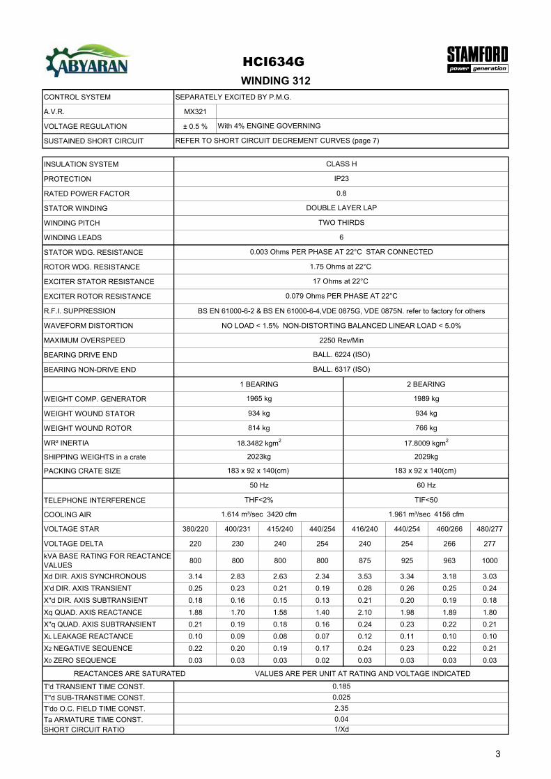
CONTROL SYSTEM SEPARATELY EXCITED BY P.M.G.
A.V.R. MX321
VOLTAGE REGULATION ± 0.5 %
SUSTAINED SHORT CIRCUIT
INSULATION SYSTEM
PROTECTION
RATED POWER FACTOR
STATOR WINDING
WINDING PITCH
WINDING LEADS
STATOR WDG. RESISTANCE
ROTOR WDG. RESISTANCE
EXCITER STATOR RESISTANCE
EXCITER ROTOR RESISTANCE
R.F.I. SUPPRESSION BS EN 61000-6-2 & BS EN 61000-6-4,VDE 0875G, VDE 0875N. refer to factory for others
WAVEFORM DISTORTION NO LOAD < 1.5% NON-DISTORTING BALANCED LINEAR LOAD < 5.0%
MAXIMUM OVERSPEED 2250 Rev/Min
BEARING DRIVE END
BEARING NON-DRIVE END
1 BEARING 2 BEARING
WEIGHT COMP. GENERATOR
WEIGHT WOUND STATOR
WEIGHT WOUND ROTOR
WR² INERTIA
SHIPPING WEIGHTS in a crate
PACKING CRATE SIZE
TELEPHONE INTERFERENCE
COOLING AIR
VOLTAGE STAR 380/220 400/231 415/240 440/254 416/240 440/254 460/266 480/277
VOLTAGE DELTA 220 230 240 254 240 254 266 277
kVA BASE RATING FOR REACTANCE VALUES
800 800 800 800 875 925 963 1000
Xd DIR. AXIS SYNCHRONOUS 3.14 2.83 2.63 2.34 3.53 3.34 3.18 3.03
X'd DIR. AXIS TRANSIENT 0.25 0.23 0.21 0.19 0.28 0.26 0.25 0.24
X''d DIR. AXIS SUBTRANSIENT 0.18 0.16 0.15 0.13 0.21 0.20 0.19 0.18
Xq QUAD. AXIS REACTANCE 1.88 1.70 1.58 1.40 2.10 1.98 1.89 1.80
X''q QUAD. AXIS SUBTRANSIENT 0.21 0.19 0.18 0.16 0.24 0.23 0.22 0.21
XL LEAKAGE REACTANCE 0.10 0.09 0.08 0.07 0.12 0.11 0.10 0.10
X2 NEGATIVE SEQUENCE 0.22 0.20 0.19 0.17 0.24 0.23 0.22 0.21
X0 ZERO SEQUENCE 0.03 0.03 0.03 0.02 0.03 0.03 0.03 0.03
REACTANCES ARE SATURATED VALUES ARE PER UNIT AT RATING AND VOLTAGE INDICATED
T'd TRANSIENT TIME CONST.
T''d SUB-TRANSTIME CONST.
T'do O.C. FIELD TIME CONST.
Ta ARMATURE TIME CONST.SHORT CIRCUIT RATIO
814 kg
17.8009 kgm2
183 x 92 x 140(cm)
18.3482 kgm2
2029kg
766 kg
1/Xd
DOUBLE LAYER LAP
1.75 Ohms at 22°C
0.003 Ohms PER PHASE AT 22°C STAR CONNECTED
6
TWO THIRDS
934 kg
1965 kg
934 kg
BALL. 6224 (ISO)
REFER TO SHORT CIRCUIT DECREMENT CURVES (page 7)
WINDING 312
With 4% ENGINE GOVERNING
0.8
IP23
CLASS H
BALL. 6317 (ISO)
17 Ohms at 22°C
0.079 Ohms PER PHASE AT 22°C
HCI634G
1.614 m³/sec 3420 cfm 1.961 m³/sec 4156 cfm
50 Hz
THF<2%
60 Hz
TIF<50
1989 kg
183 x 92 x 140(cm)
2023kg
0.185
0.025
2.35
0.04
3
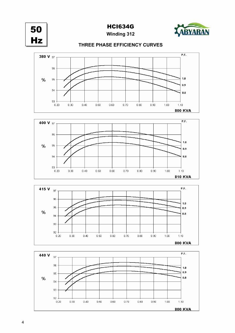
Winding 312HCI634G
THREE PHASE EFFICIENCY CURVES
50Hz
4
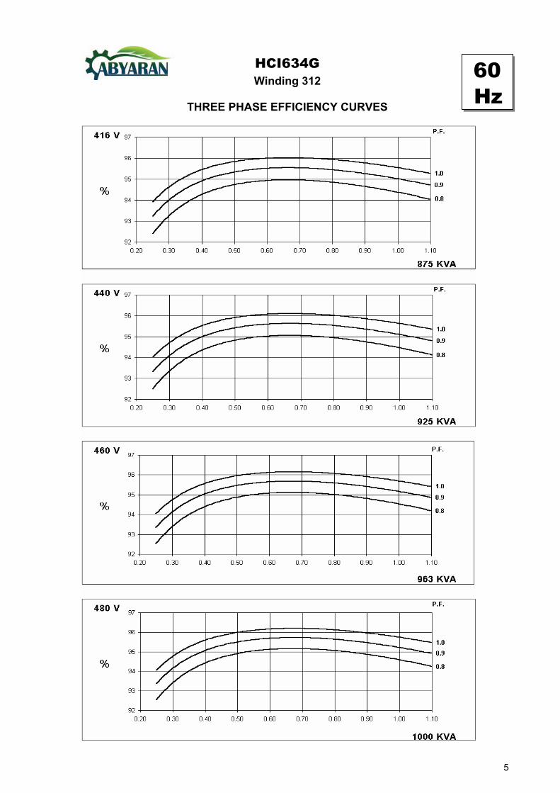
Winding 312HCI634G
THREE PHASE EFFICIENCY CURVES
60Hz
5

HCI634GWinding 312
Locked Rotor Motor Starting Curve
0
5
10
15
20
25
30
0 200 400 600 800 1000 1200 1400 1600 1800 2000 2200LOCKED ROTOR kVA
PE
R C
EN
T T
RA
NS
IEN
T V
OL
TA
GE
DIP
.
346V 380V 400V 415V 440V
0
5
10
15
20
25
30
0 200 400 600 800 1000 1200 1400 1600 1800 2000 2200 2400 2600LOCKED ROTOR kVA
PE
R C
EN
T T
RA
NS
IEN
T V
OL
TA
GE
DIP
.
380V 416V 440V 460V 480V
60Hz
50Hz
6

3-phase 2-phase L-L 1-phase L-NVoltage Factor Voltage Factor x 1.00 x 0.87 x 1.30
380v X 1.00 416v x 1.00 x 1.00 x 1.80 x 3.20400v X 1.07 440v x 1.06 x 1.00 x 1.50 x 2.50415v X 1.12 460v x 1.12 10 sec. 5 sec. 2 sec.440v X 1.18 480v x 1.17
HCI634G
50Hz 60Hz
The sustained current value is constant irrespectiveof voltage level
Three-phase Short Circuit Decrement Curve. No-load Excitation at Rated SpeedBased on star (wye) connection.
Max. sustained durationAll other times are unchanged
Instantaneous
SustainedMinimum
Sustained Short Circuit = 2,900 Amps
Sustained Short Circuit = 3,500 AmpsNote 1The following multiplication factors should beused to adjust the values from curve betweentime 0.001 seconds and the minimum currentpoint in respect of nominal operating voltage :
Note 2The following multiplication factor should be used to convert thevalues calculated in accordance with NOTE 1 to those applicableto the various types of short circuit :
Note 3Curves are drawn for Star (Wye) connected machines. For Deltaconnection multiply the Curve current value by 1.732
50Hz
60Hz
1000
10000
100000
0.001 0.01 0.1 1 10TIME (secs)
CU
RR
EN
T (A
mp
s)
SYMMETRICAL
ASYMMETRICAL
1000
10000
100000
0.001 0.01 0.1 1 10TIME (secs)
CU
RR
EN
T (A
mp
s)
SYMMETRICAL
ASYMMETRICAL
7
Class - Temp Rise
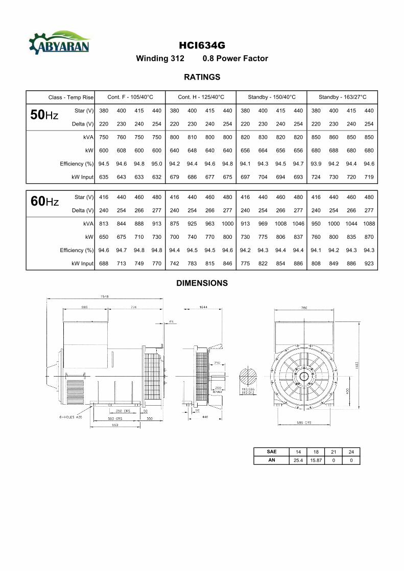
Star (V) 380 400 415 440 380 400 415 440 380 400 415 440 380 400 415 440
Delta (V) 220 230 240 254 220 230 240 254 220 230 240 254 220 230 240 254
kVA 750 760 750 750 800 810 800 800 820 830 820 820 850 860 850 850
kW 600 608 600 600 640 648 640 640 656 664 656 656 680 688 680 680
Efficiency (%) 94.5 94.6 94.8 95.0 94.2 94.4 94.6 94.8 94.1 94.3 94.5 94.7 93.9 94.2 94.4 94.6
kW Input 635 643 633 632 679 686 677 675 697 704 694 693 724 730 720 719
Star (V) 416 440 460 480 416 440 460 480 416 440 460 480 416 440 460 480
Delta (V) 240 254 266 277 240 254 266 277 240 254 266 277 240 254 266 277
kVA 813 844 888 913 875 925 963 1000 913 969 1008 1046 950 1000 1044 1088
kW 650 675 710 730 700 740 770 800 730 775 806 837 760 800 835 870
Efficiency (%) 94.6 94.7 94.8 94.8 94.4 94.5 94.5 94.6 94.2 94.3 94.4 94.4 94.1 94.2 94.3 94.3
kW Input 688 713 749 770 742 783 815 846 775 822 854 886 808 849 886 923
14 18 21 24
25.4 15.87 0 0
SAE
AN
DIMENSIONS
HCI634G
Cont. F - 105/40°C Cont. H - 125/40°C Standby - 150/40°C Standby - 163/27°C
Winding 312 0.8 Power Factor
RATINGS
50Hz
60Hz