generator users group annual conference 2015 · generator users group annual conference 2015 core...
TRANSCRIPT

Generator Users Group Annual Conference 2015
Core testing, low and high flux, tap
Mladen Sasic, IRIS Power

Stator Cores
• Cores provide low reluctance paths for working magnetic fluxes
• Support stator winding, together with stator wedges!
• Cores and wedges must be capable of withstanding operating forces: mechanical and magnetic
• Core provides primary heat removal from indirect cooled stator winding

Westinghouse Core

GE Core

What is in the slot?

Requirement for Wedge Testing
Wedges are installed to hold coils firmly in place and eliminate vibration
Vibration results in wear and erosion of insulation
Over time, this can result in electrical failure
Loose or improperly installed wedges have been identified as a major contributor to this problem
All manufacturers agree on the need for well installed and maintained wedges

Various wedge types

Top Ripple Spring
30 mm 1.8 mm
Thickness: 0.9 mm, length and width to fit the slot/wedge Normal compression in 75-90% range

Side Ripple Spring

Stator Bar Slot Vibration Control
10

Typical tests
• Visual inspection (end wedge/side filler migration)
• Evidence of greasing, dusting
• Displacement measurements
• Ripple Spring Compression measurement
• Tap tests (manual or electronic)

Typical Tools...

Typical Problems...
TIGHT !!!
LOOSE...
????

Typical Electronic Tools...

RTI Idea
Measured (raw) values are compared to user selected references for tight and loose
RTI (Relative Tightness Index, number from 0-100) is displayed as a result of comparison between measured values and references
Different calibration references will produce different RTI
RTIs are not saved in measurement file

RTI Summary
Tap test conclusion
• A lot of uncertainty with any method
• Personal feel often considered to be more accurate than electronic methods
• There is no unit for “tightness” and…
• …there is no agreement on tight and loose
• Introduction of on-line methods may be helpful

18
Stator Core Testing
Mechanical and Electrical tests:
• Core tightness test
• Core vibration test
• Through Bolts Insulation
• Core loss test
• Rated flux test
• Low flux tests

19
Core Tightness Testing
• Visual inspection
• Suspected loose areas can be confirmed by a “Knife Test”.
• This involves trying to insert a knife with a 0.25 mm (10 thou) thick blade into the core bore (stator) or OD (rotor).
• If the knife penetrates more than 5.0 mm (0.2 ins) then the core is loose.
• EDF “Crabe”
• Bump test, 15-20 slots tested on hydro core, more air in core= lower the acoustic wave speed.

20
Knife Test

When you “test the core”…
What do you actually measure?
• Core loss test: W/kg
• LOOP test: temperature
• Low power core test: mA or W

…and what can affect your result?
• Core loss and LOOP test: quality of material, test time, induction level…
• Low power tests: quality and uniformity of material, induction level…
• Magnetic permeability and core loss variation may be detected with low power test but not with LOOP test

23
Core Loss Test
• Core is excited and power absorbed measured by a wattmeter
• Results are expressed as loss per mass of core
• Should not exceed about 6-10W/kg
• Increase from previous test should not be more than 5%

24
Rated Flux Test Purpose and Theory
• The induced flux will generate excessive heating in the areas of core where degraded core insulation exists
• Heat is generated by eddy currents flowing between lamination due to insulation degradation
• Excitation winding power supply system should be fitted with a voltage adjustment device, ammeter to obtain the correct ampere-turns to produced the required flux
• No agreement on excitation levels, test duration and acceptance criteria

25
Rated Flux Test

26
Rated Flux Test
• Two methods to calculate flux test level, i.e. turn voltage:
-Winding diagram
-Size of the core
See IEEE 56 or IEEE 432

27
Magnetization curve

28
Rated Flux Test on Turbo

29
POWER
SOURCE
Power
Cables
Rated Flux Test on Hydro

30
Rated Flux Test
~15C above ambient

31
Rated Flux Concerns
• High Voltage, Current and Magnetic Field
• Fixed voltage supply
• Localized core burning
• General core overheating
• Temperature attenuation
• Labour intensive
• Uncertain power requirements
• Different flux patterns compared to normal operation

Low power core testing
• Recommended test level for low power tests is in range of 2-10 % of nominal flux.
• For 4% level, it is close to 5V/m of core length for two pole turbo generators, but…
• It is NOT 5V/m for hydro and motor cores!
• To achieve 4%, about 10 At/m (vs. 100-1000 in LOOP) of core circumference is required, or 100-600 At.
• Different instruments exist

33
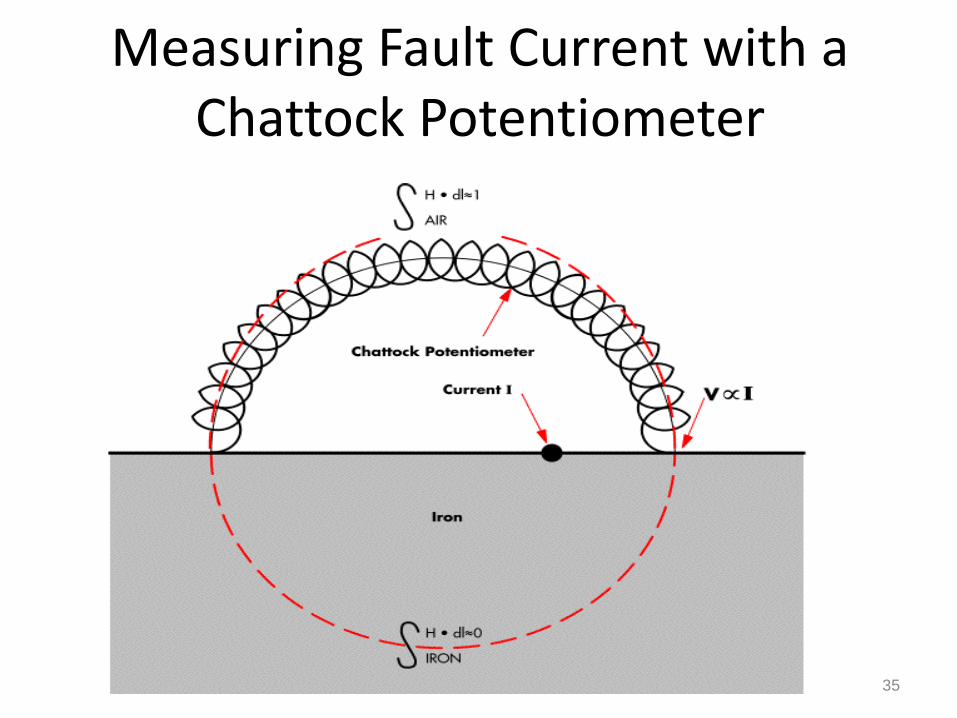
EL CID Test Purpose and Theory
• EL CID is the abbreviation for “Electromagnetic Core Imperfection Detector”
• Works on the principle that:
If a low flux around 4% of rated flux is induced in back of core currents flow through defective core insulation
Current is measured with Chattock Coil
Chattock Coil gives voltage output proportional to fault current (IQUAD) and current (IPHASE) produced by the flux induced flux

34
EL CID principle
Insulation breakdown causes fault currents to be set up as illustrated. These fault currents create hot spots which can cause further deterioration to the core. If left unchecked, this can lead to damage to the stator winding and the machine as a whole.
35
Measuring Fault Current with a Chattock Potentiometer

36
Positioning the Chattock

Understanding Fault Magnitude
IQUAD 100mA at 4%
equates to 5-10°C on LOOP Test

Data Display – Normal Traces

Core Visualisation

Advantages of EL CID
Low Excitation Power - 4%
No Risk of Further core damage
Fast, Portable - Easy to Setup
Low Manpower Requirements
Significant Reduction in Safety Hazards
Instant Interpretation of Test Results
Ability to Re-Test During Maintenance Cycle
Can be done with rotor in place

41
Disadvantages of EL CID
Requires competent trained test technician and experience to
interpret data (also with LOOP Test)
Difficult to detect small faults at the joints in hydro-generator
cores
Correlation to Ring Flux Test not perfect
Faults on cores with insulated key-bars difficult to detect (also
with LOOP Test)
Does not create the same flux pattern as in operation (also
with LOOP test)

What is an acceptable result?
• Core Loss: 6-10 W/kg
• Loop test: 5-10 K at 100% of nominal flux
• Low power tests: Less than 100 mA of quad current at 4% excitation level or 15 W dissipation at 3-10 %

Conclusions
• “Evaluation of the condition of a core is a major technical challenge” - C. Maughan
• Visual inspection is very important
• Both, high and low flux tests, have limitations
• Core problems are not that frequent, but…