genesis ii acf - smith & nephew
TRANSCRIPT
Surgical Technique
Anterior Cut First Surgical Technique
2
Introduction
The GENESIS™ II Total Knee System has been designed to offer theorthopaedic surgeon solutions to address intraoperative situations.Implant function is directly related to accurate surgical technique.GENESIS II instrumentation has been developed to be an easy-to-use system that will assist the surgeon in obtainingaccurate and reproducible knee alignment.
The instrumentation can be used in minimally invasive or standardexposures. While it has been the designers’ objective to developaccurate, easy-to-use instrumentation, each surgeon must evaluatethe appropriateness of the following technique based on his or hermedical training, experience and patient evaluation.
Contributing Clinicians
Robert B. Bourne, MD, FRCSCChief of Orthopaedic SurgeryUniversity HospitalThe University of Western OntarioLondon, Ontario, Canada
Steven B. Haas, MD, MPHAssociate Professor of Orthopaedic SurgeryWeill Medical College of Cornell UniversityAssociate Chief of the Knee ServiceThe Hospital for Special SurgeryNew York, New York
Richard S. Laskin, MDProfessor of Orthopaedic SurgeryWeill Medical College of Cornell UniversityCo-Chief, Knee ServiceThe Hospital for Special SurgeryNew York, New York
Michael D. Ries, MDProfessor and Vice Chairman University of California, San FranciscoDepartment of Orthopaedic SurgerySan Francisco, CA
William B. Smith, MDAssistant Clinical Professor in Orthopaedic SurgeryMedical College of WisconsinColumbia HospitalMilwaukee, Wisconsin
Mark A. Snyder, MDClinical InstructorUniversity of CincinnatiOrthopaedic SurgeonChrist HospitalCincinnati, Ohio
Todd V. Swanson, MDDesert Orthopaedic CenterLas Vegas, Nevada
Jan Victor, MDDepartment of OrthopaedicsSt. Lucas HospitalBrugge, Belgium
3
ACF Short Technique . . . . . . . . . . . . . . . . . . . . . . . . . . . . . . . . . . . . 4
Preop Planning . . . . . . . . . . . . . . . . . . . . . . . . . . . . . . . . . . . . . . . . . 6
Femoral Preparation . . . . . . . . . . . . . . . . . . . . . . . . . . . . . . . . . . . . .7
Tibial Preparation . . . . . . . . . . . . . . . . . . . . . . . . . . . . . . . . . . . . . . 17
Tibial Sizing . . . . . . . . . . . . . . . . . . . . . . . . . . . . . . . . . . . . . . . . . . . 26
Posterior-Stabilized Femoral Resection . . . . . . . . . . . . . . . . . . . 28
Resurfacing Patellar Preparation . . . . . . . . . . . . . . . . . . . . . . . . . 30
Biconvex Patellar Preparation . . . . . . . . . . . . . . . . . . . . . . . . . . . . 37
Component Trialing . . . . . . . . . . . . . . . . . . . . . . . . . . . . . . . . . . . . .39
Implantation . . . . . . . . . . . . . . . . . . . . . . . . . . . . . . . . . . . . . . . . . . .42
Appendix A: GENESIS™ II P-S High Flex Insert Impaction Technique for MIS . . . . . . . . . . . . . . . . . . . . . . .45
Appendix B: Articular Insert Interchangeability Chart . . . . . . . .46
Nota Bene:The technique description herein is made available to the healthcare professional to illustrate the authors’ suggested treatment for the uncomplicated procedure. In the final analysis, the preferred treatment is that which addresses the needs of the patient.
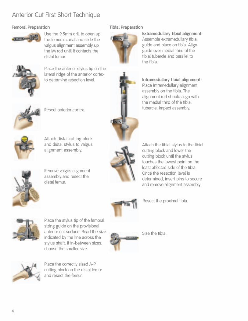
Anterior Cut First Short Technique
Use the 9.5mm drill to open upthe femoral canal and slide thevalgus alignment assembly up the IM rod until it contacts thedistal femur.
Attach distal cutting block and distal stylus to valgusalignment assembly.
4
Place the anterior stylus tip on thelateral ridge of the anterior cortexto determine resection level.
Resect anterior cortex.
Remove valgus alignmentassembly and resect the distal femur.
Place the stylus tip of the femoralsizing guide on the provisionalanterior cut surface. Read the sizeindicated by the line across thestylus shaft. If in-between sizes,choose the smaller size.
Place the correctly sized A-Pcutting block on the distal femurand resect the femur.
Extramedullary tibial alignment:Assemble extramedullary tibialguide and place on tibia. Alignguide over medial third of thetibial tubercle and parallel to the tibia.
Intramedullary tibial alignment:Place intramedullary alignmentassembly on the tibia. Thealignment rod should align withthe medial third of the tibialtubercle. Impact assembly.
Attach the tibial stylus to the tibialcutting block and lower thecutting block until the stylustouches the lowest point on theleast affected side of the tibia.Once the resection level isdetermined, insert pins to secureand remove alignment assembly.
Resect the proximal tibia.
Size the tibia.
Femoral Preparation Tibial Preparation
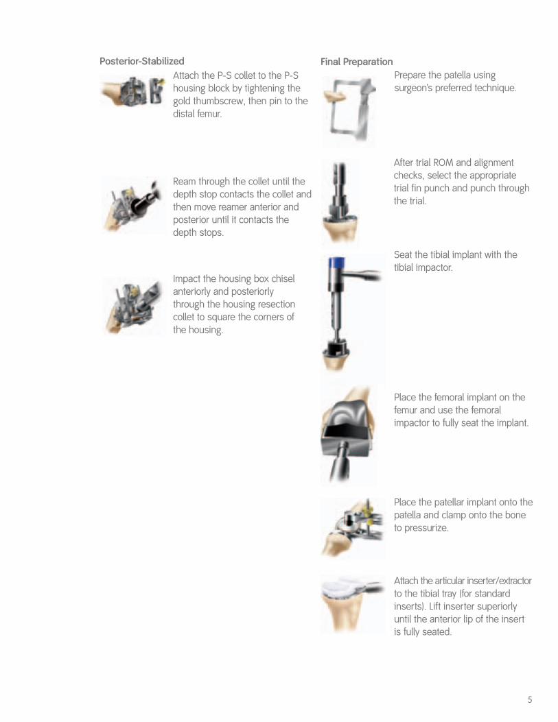
Attach the P-S collet to the P-Shousing block by tightening thegold thumbscrew, then pin to thedistal femur.
5
Ream through the collet until thedepth stop contacts the collet andthen move reamer anterior andposterior until it contacts thedepth stops.
Impact the housing box chiselanteriorly and posteriorly through the housing resectioncollet to square the corners of the housing.
Posterior-Stabilized
After trial ROM and alignmentchecks, select the appropriatetrial fin punch and punch throughthe trial.
Seat the tibial implant with thetibial impactor.
Place the femoral implant on thefemur and use the femoralimpactor to fully seat the implant.
Place the patellar implant onto thepatella and clamp onto the boneto pressurize.
Attach the articular inserter/extractorto the tibial tray (for standardinserts). Lift inserter superiorlyuntil the anterior lip of the insertis fully seated.
Prepare the patella usingsurgeon’s preferred technique.
Final Preparation
6
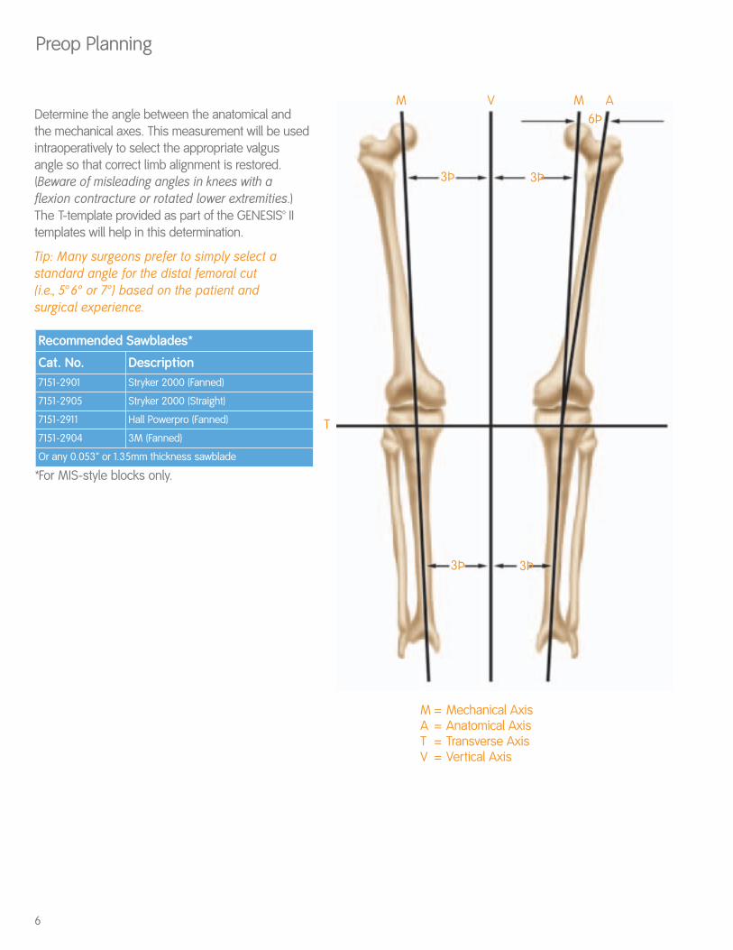
Preop Planning
M
M = Mechanical AxisA = Anatomical AxisT = Transverse AxisV = Vertical Axis
M
3Þ3Þ
3Þ3Þ
6ÞA
T
VDetermine the angle between the anatomical andthe mechanical axes. This measurement will be usedintraoperatively to select the appropriate valgusangle so that correct limb alignment is restored.(Beware of misleading angles in knees with aflexion contracture or rotated lower extremities.)The T-template provided as part of the GENESIS™ IItemplates will help in this determination.
Tip: Many surgeons prefer to simply select astandard angle for the distal femoral cut (i.e., 5° 6° or 7°) based on the patient and surgical experience.
*For MIS-style blocks only.
Recommended Sawblades*
Cat. No. Description7151-2901 Stryker 2000 (Fanned)
7151-2905 Stryker 2000 (Straight)
7151-2911 Hall Powerpro (Fanned)
7151-2904 3M (Fanned)
Or any 0.053" or 1.35mm thickness sawblade
7
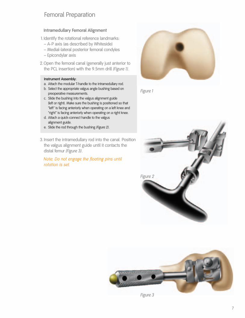
Figure 1
Femoral Preparation
Intramedullary Femoral Alignment
1. Identify the rotational reference landmarks:– A-P axis (as described by Whiteside) – Medial-lateral posterior femoral condyles – Epicondylar axis
2.Open the femoral canal (generally just anterior tothe PCL insertion) with the 9.5mm drill (Figure 1).
Instrument Assembly: a. Attach the modular T-handle to the intramedullary rod.b. Select the appropriate valgus angle bushing based on
preoperative measurements. c. Slide the bushing into the valgus alignment guide
(left or right). Make sure the bushing is positioned so that“left” is facing anteriorly when operating on a left knee and “right” is facing anteriorly when operating on a right knee.
d. Attach a quick-connect handle to the valgus alignment guide.
e. Slide the rod through the bushing (Figure 2).
3. Insert the intramedullary rod into the canal. Positionthe valgus alignment guide until it contacts thedistal femur (Figure 3).
Note: Do not engage the floating pins untilrotation is set.
Figure 2
Figure 3
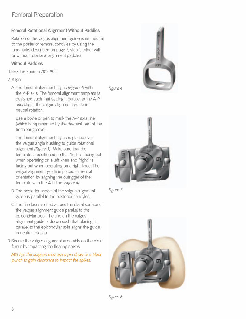
Femoral Rotational Alignment Without Paddles
Rotation of the valgus alignment guide is set neutralto the posterior femoral condyles by using thelandmarks described on page 7, step 1, either withor without rotational alignment paddles.
Without Paddles
1. Flex the knee to 70°- 90°.
2.Align:
A.The femoral alignment stylus (Figure 4) withthe A-P axis. The femoral alignment template is designed such that setting it parallel to the A-P axis aligns the valgus alignment guide in neutral rotation.
Use a bovie or pen to mark the A-P axis line (which is represented by the deepest part of the trochlear groove).
The femoral alignment stylus is placed over the valgus angle bushing to guide rotational alignment (Figure 5). Make sure that the template is positioned so that “left” is facing out when operating on a left knee and “right” is facing out when operating on a right knee. The valgus alignment guide is placed in neutral orientation by aligning the outrigger of the template with the A-P line (Figure 6).
B. The posterior aspect of the valgus alignment guide is parallel to the posterior condyles.
C. The line laser-etched across the distal surface of the valgus alignment guide parallel to the epicondylar axis. The line on the valgus alignment guide is drawn such that placing it parallel to the epicondylar axis aligns the guide in neutral rotation.
3.Secure the valgus alignment assembly on the distalfemur by impacting the floating spikes.
MIS Tip: The surgeon may use a pin driver or a tibialpunch to gain clearance to impact the spikes.
8
Femoral Preparation
Figure 4
Figure 6
Figure 5
9
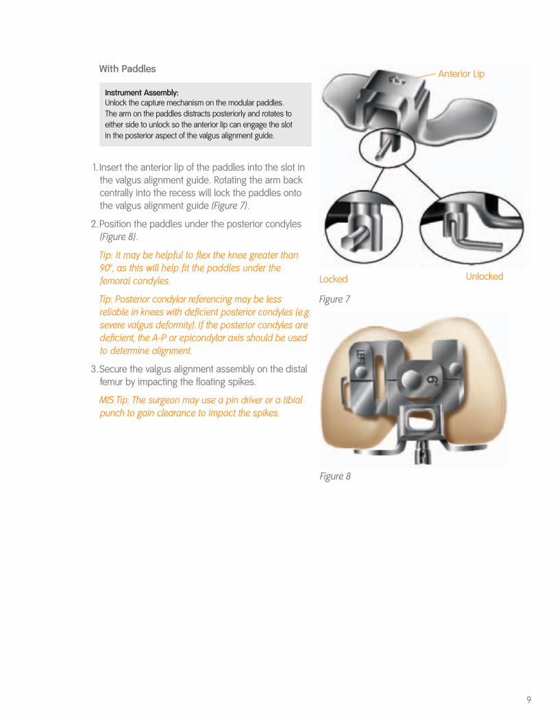
With Paddles
Instrument Assembly: Unlock the capture mechanism on the modular paddles. The arm on the paddles distracts posteriorly and rotates toeither side to unlock so the anterior lip can engage the slotin the posterior aspect of the valgus alignment guide.
1. Insert the anterior lip of the paddles into the slot inthe valgus alignment guide. Rotating the arm backcentrally into the recess will lock the paddles ontothe valgus alignment guide (Figure 7).
2.Position the paddles under the posterior condyles(Figure 8).
Tip: It may be helpful to flex the knee greater than90°, as this will help fit the paddles under thefemoral condyles.
Tip: Posterior condylar referencing may be lessreliable in knees with deficient posterior condyles (e.g.severe valgus deformity). If the posterior condyles aredeficient, the A-P or epicondylar axis should be usedto determine alignment.
3.Secure the valgus alignment assembly on the distalfemur by impacting the floating spikes.
MIS Tip: The surgeon may use a pin driver or a tibialpunch to gain clearance to impact the spikes.
Figure 8
Unlocked
Anterior Lip
Figure 7
Locked
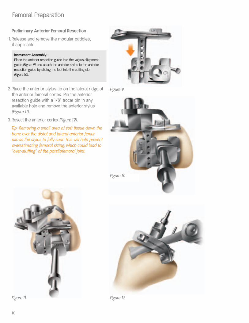
Preliminary Anterior Femoral Resection
1.Release and remove the modular paddles, if applicable.
Instrument Assembly: Place the anterior resection guide into the valgus alignmentguide (Figure 9) and attach the anterior stylus to the anterior resection guide by sliding the foot into the cutting slot (Figure 10).
2.Place the anterior stylus tip on the lateral ridge ofthe anterior femoral cortex. Pin the anteriorresection guide with a 1/8" trocar pin in anyavailable hole and remove the anterior stylus(Figure 11).
3.Resect the anterior cortex (Figure 12).
Tip: Removing a small area of soft tissue down thebone over the distal and lateral anterior femurallows the stylus to fully seat. This will help preventoverestimating femoral sizing, which could lead to“over-stuffing” of the patellofemoral joint.
10
Femoral Preparation
Figure 9
Figure 10
Figure 12Figure 11
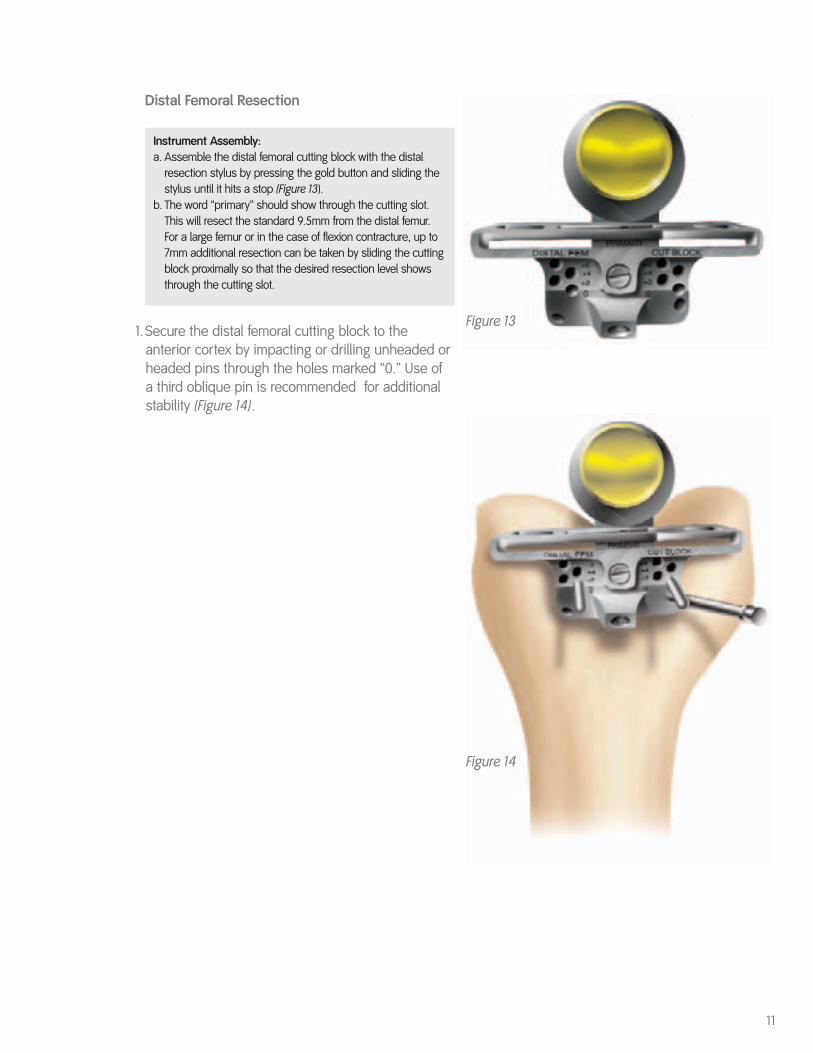
Distal Femoral Resection
Instrument Assembly: a. Assemble the distal femoral cutting block with the distal
resection stylus by pressing the gold button and sliding the stylus until it hits a stop (Figure 13).
b. The word “primary” should show through the cutting slot. This will resect the standard 9.5mm from the distal femur. For a large femur or in the case of flexion contracture, up to 7mm additional resection can be taken by sliding the cutting block proximally so that the desired resection level shows through the cutting slot.
1.Secure the distal femoral cutting block to theanterior cortex by impacting or drilling unheaded orheaded pins through the holes marked “0.” Use ofa third oblique pin is recommended for additionalstability (Figure 14).
11
Figure 13
Figure 14
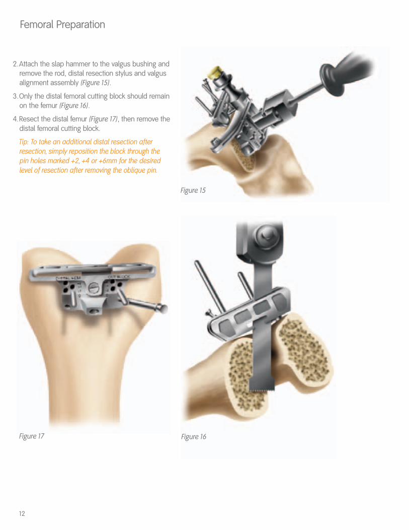
2.Attach the slap hammer to the valgus bushing andremove the rod, distal resection stylus and valgusalignment assembly (Figure 15).
3.Only the distal femoral cutting block should remainon the femur (Figure 16).
4.Resect the distal femur (Figure 17), then remove thedistal femoral cutting block.
Tip: To take an additional distal resection afterresection, simply reposition the block through the pin holes marked +2, +4 or +6mm for the desiredlevel of resection after removing the oblique pin.
12
Femoral Preparation
Figure 17
Figure 15
Figure 16
13
Figure 18
Figure 19
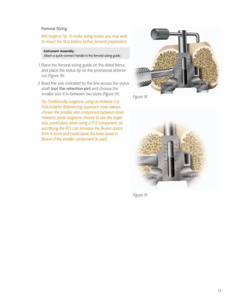
Femoral Sizing
MIS Surgical Tip: To make sizing easier, you may wishto resect the tibia before further femoral preparation.
Instrument Assembly: Attach a quick-connect handle to the femoral sizing guide.
1.Place the femoral sizing guide on the distal femur,and place the stylus tip on the provisional anteriorcut (Figure 18).
2.Read the size indicated by the line across the stylusshaft (not the retention pin) and choose thesmaller size if in-between two sizes (Figure 19).
Tip: Traditionally, surgeons using an Anterior CutFirst/Anterior Referencing approach have alwayschosen the smaller size component between sizes.However, some surgeons choose to use the largersize, particularly when using a P-S component, assacrificing the PCL can increase the flexion spacefrom 4-6mm and could leave the knee loose inflexion if the smaller component is used.
14
Femoral Preparation
Figure 21 Figure 22
Figure 23 Figure 24
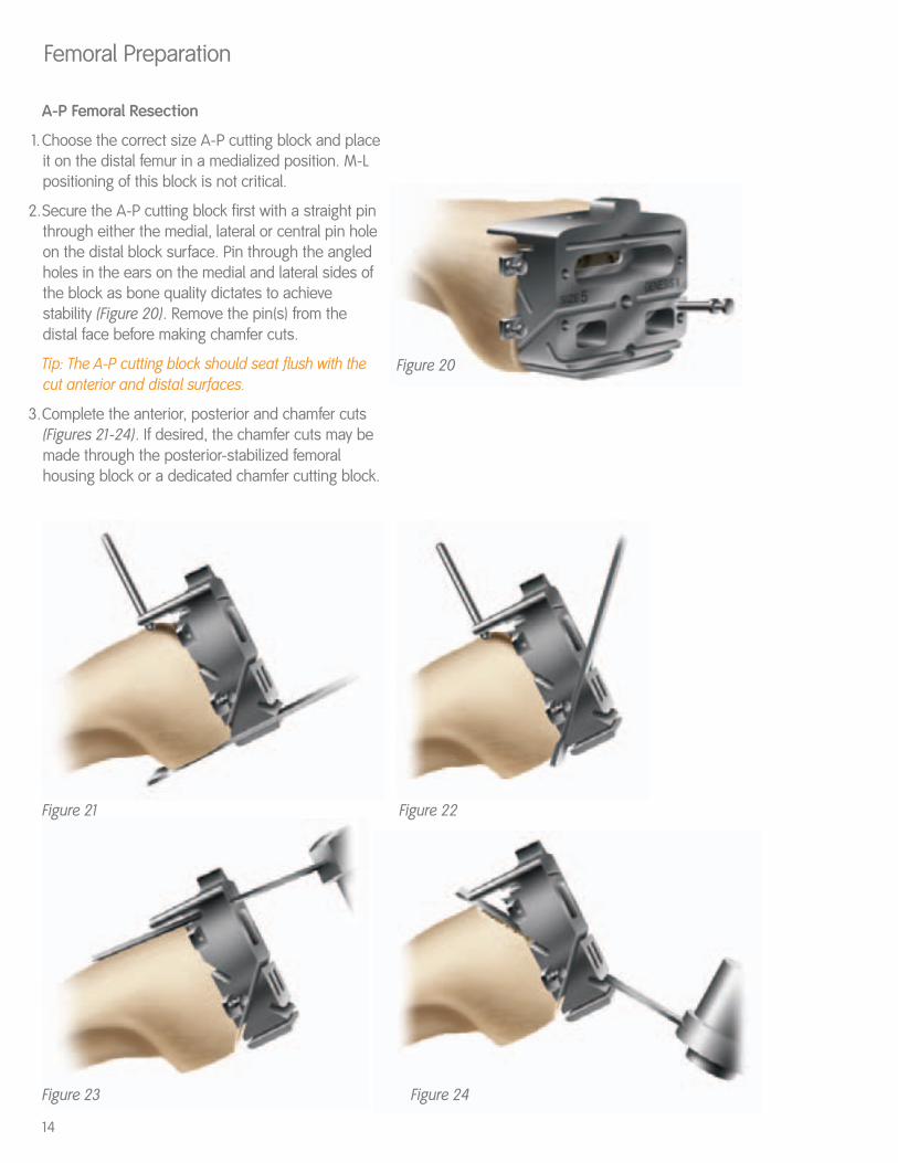
A-P Femoral Resection
1.Choose the correct size A-P cutting block and placeit on the distal femur in a medialized position. M-Lpositioning of this block is not critical.
2.Secure the A-P cutting block first with a straight pinthrough either the medial, lateral or central pin holeon the distal block surface. Pin through the angledholes in the ears on the medial and lateral sides ofthe block as bone quality dictates to achievestability (Figure 20). Remove the pin(s) from thedistal face before making chamfer cuts.
Tip: The A-P cutting block should seat flush with thecut anterior and distal surfaces.
3.Complete the anterior, posterior and chamfer cuts(Figures 21-24). If desired, the chamfer cuts may bemade through the posterior-stabilized femoralhousing block or a dedicated chamfer cutting block.
Figure 20
Tibial Preparation
Figure 26
15Figure 29
Figure 28Figure 27
gold knob
central knob
locking cam
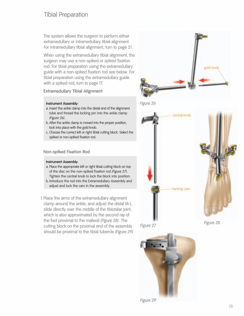
The system allows the surgeon to perform eitherextramedullary or intramedullary tibial alignment.For intramedullary tibial alignment, turn to page 21.
When using the extramedullary tibial alignment, thesurgeon may use a non-spiked or spiked fixationrod. For tibial preparation using the extramedullaryguide with a non-spiked fixation rod see below. Fortibial preparation using the extramedullary guidewith a spiked rod, turn to page 17.
Extramedullary Tibial Alignment
Instrument Assembly: a. Insert the ankle clamp into the distal end of the alignment
tube and thread the locking pin into the ankle clamp (Figure 26).
b. After the ankle clamp is moved into the proper position, lock into place with the gold knob.
c. Choose the correct left or right tibial cutting block. Select the spiked or non-spiked fixation rod.
Non-spiked Fixation Rod
Instrument Assembly: a. Place the appropriate left or right tibial cutting block on top
of the disc on the non-spiked fixation rod (Figure 27). Tighten the central knob to lock the block into position.
b. Introduce the rod into the Extramedullary Assembly and adjust and lock the cam in the assembly.
1.Place the arms of the extramedullary alignmentclamp around the ankle, and adjust the distal M-Lslide directly over the middle of the tibiotalar joint,which is also approximated by the second ray ofthe foot proximal to the malleoli (Figure 28). Thecutting block on the proximal end of the assemblyshould be proximal to the tibial tubercle (Figure 29).
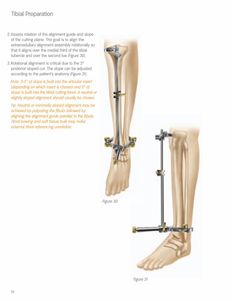
2.Assess rotation of the alignment guide and slope of the cutting plane. The goal is to align theextramedullary alignment assembly rotationally sothat it aligns over the medial third of the tibialtubercle and over the second toe (Figure 30).
3.Rotational alignment is critical due to the 3ºposterior sloped cut. The slope can be adjustedaccording to the patient’s anatomy (Figure 31).
Note: 3-5° of slope is built into the articular insert(depending on which insert is chosen) and 3º ofslope is built into the tibial cutting block. A neutral orslightly sloped alignment should usually be chosen.
Tip: Neutral or minimally sloped alignment may beachieved by palpating the fibula followed byaligning the alignment guide parallel to the fibula.Tibial bowing and soft tissue bulk may makeexternal tibial referencing unreliable.
Tibial Preparation
16
Figure 30
Figure 31
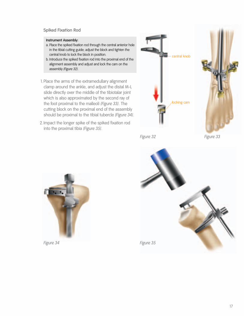
Spiked Fixation Rod
Instrument Assembly: a. Place the spiked fixation rod through the central anterior hole
in the tibial cutting guide; adjust the block and tighten the central knob to lock the block in position.
b. Introduce the spiked fixation rod into the proximal end of the alignment assembly and adjust and lock the cam on the assembly (Figure 32).
1.Place the arms of the extramedullary alignmentclamp around the ankle, and adjust the distal M-Lslide directly over the middle of the tibiotalar jointwhich is also approximated by the second ray ofthe foot proximal to the malleoli (Figure 33). Thecutting block on the proximal end of the assemblyshould be proximal to the tibial tubercle (Figure 34).
2.Impact the longer spike of the spiked fixation rodinto the proximal tibia (Figure 35).
17
Figure 35
Figure 32 Figure 33
central knob
locking cam
Figure 34
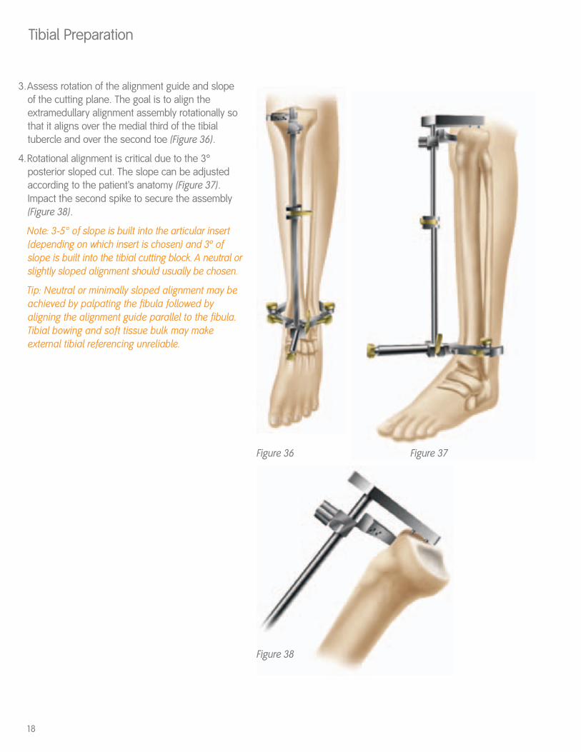
3.Assess rotation of the alignment guide and slope of the cutting plane. The goal is to align theextramedullary alignment assembly rotationally sothat it aligns over the medial third of the tibialtubercle and over the second toe (Figure 36).
4.Rotational alignment is critical due to the 3ºposterior sloped cut. The slope can be adjustedaccording to the patient’s anatomy (Figure 37).Impact the second spike to secure the assembly(Figure 38).
Note: 3-5° of slope is built into the articular insert(depending on which insert is chosen) and 3º ofslope is built into the tibial cutting block. A neutral orslightly sloped alignment should usually be chosen.
Tip: Neutral or minimally sloped alignment may beachieved by palpating the fibula followed byaligning the alignment guide parallel to the fibula.Tibial bowing and soft tissue bulk may makeexternal tibial referencing unreliable.
Tibial Preparation
18
Figure 38
Figure 36 Figure 37
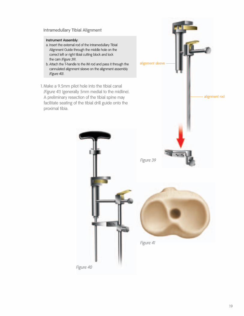
Intramedullary Tibial Alignment
Instrument Assembly: a. Insert the external rod of the Intramedullary Tibial
Alignment Guide through the middle hole on the correct left or right tibial cutting block and lock the cam (Figure 39).
b. Attach the T-handle to the IM rod and pass it through the cannulated alignment sleeve on the alignment assembly (Figure 40).
1.Make a 9.5mm pilot hole into the tibial canal (Figure 41) (generally 5mm medial to the midline). A preliminary resection of the tibial spine mayfacilitate seating of the tibial drill guide onto theproximal tibia.
19
Figure 39
Figure 40
Figure 41
alignment rod
alignment sleeve
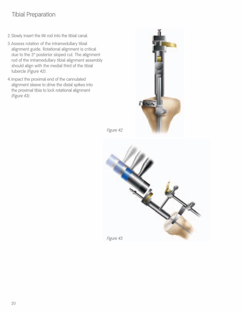
2.Slowly insert the IM rod into the tibial canal.
3.Assess rotation of the intramedullary tibialalignment guide. Rotational alignment is criticaldue to the 3º posterior sloped cut. The alignmentrod of the intramedullary tibial alignment assemblyshould align with the medial third of the tibialtubercle (Figure 42).
4.Impact the proximal end of the cannulatedalignment sleeve to drive the distal spikes into the proximal tibia to lock rotational alignment (Figure 43).
Tibial Preparation
20
Figure 42
Figure 43
Tibial Resection
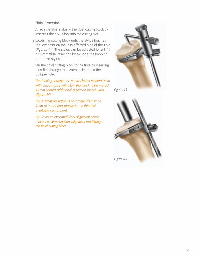
1.Attach the tibial stylus to the tibial cutting block byinserting the stylus foot into the cutting slot.
2.Lower the cutting block until the stylus touches the low point on the less affected side of the tibia(Figures 44). The stylus can be adjusted for a 9, 11or 13mm tibial resection by twisting the knob ontop of the stylus.
3.Pin the tibial cutting block to the tibia by insertingpins first through the central holes; then theoblique hole.
Tip: Pinning through the central holes marked 0mmwith smooth pins will allow the block to be moved+2mm should additional resection be required(Figure 45).
Tip: A 9mm resection is recommended since9mm of metal and plastic is the thinnestavailable component.
Tip: To do an extramedullary alignment check,place the extramedullary alignment rod throughthe tibial cutting block.
21
Figure 44
Figure 45
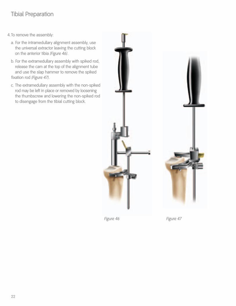
4.To remove the assembly:
a. For the intramedullary alignment assembly, use the universal extractor leaving the cutting block on the anterior tibia (Figure 46).
b. For the extramedullary assembly with spiked rod, release the cam at the top of the alignment tube and use the slap hammer to remove the spiked
fixation rod (Figure 47).
c. The extramedullary assembly with the non-spikedrod may be left in place or removed by loosening the thumbscrew and lowering the non-spiked rodto disengage from the tibial cutting block.
Tibial Preparation
22
Figure 46 Figure 47
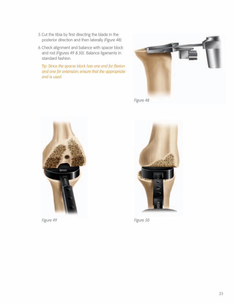
5.Cut the tibia by first directing the blade in theposterior direction and then laterally (Figure 48).
6.Check alignment and balance with spacer blockand rod (Figures 49 & 50). Balance ligaments instandard fashion.
Tip: Since the spacer block has one end for flexionand one for extension, ensure that the appropriateend is used.
23
Figure 48
Figure 49 Figure 50
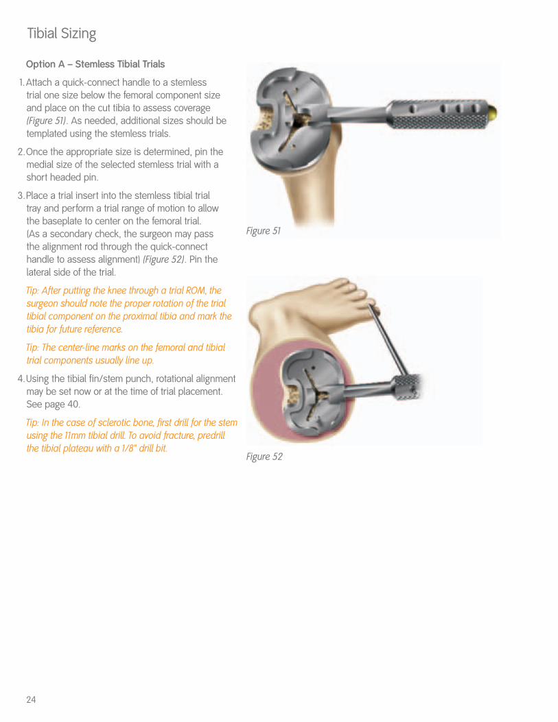
Option A – Stemless Tibial Trials
1.Attach a quick-connect handle to a stemless trial one size below the femoral component sizeand place on the cut tibia to assess coverage(Figure 51). As needed, additional sizes should betemplated using the stemless trials.
2.Once the appropriate size is determined, pin themedial size of the selected stemless trial with ashort headed pin.
3.Place a trial insert into the stemless tibial trial tray and perform a trial range of motion to allow the baseplate to center on the femoral trial. (As a secondary check, the surgeon may pass the alignment rod through the quick-connecthandle to assess alignment) (Figure 52). Pin thelateral side of the trial.
Tip: After putting the knee through a trial ROM, thesurgeon should note the proper rotation of the trialtibial component on the proximal tibia and mark thetibia for future reference.
Tip: The center-line marks on the femoral and tibialtrial components usually line up.
4.Using the tibial fin/stem punch, rotational alignmentmay be set now or at the time of trial placement.See page 40.
Tip: In the case of sclerotic bone, first drill for the stemusing the 11mm tibial drill. To avoid fracture, predrillthe tibial plateau with a 1/8" drill bit.
Tibial Sizing
24
Figure 51
Figure 52
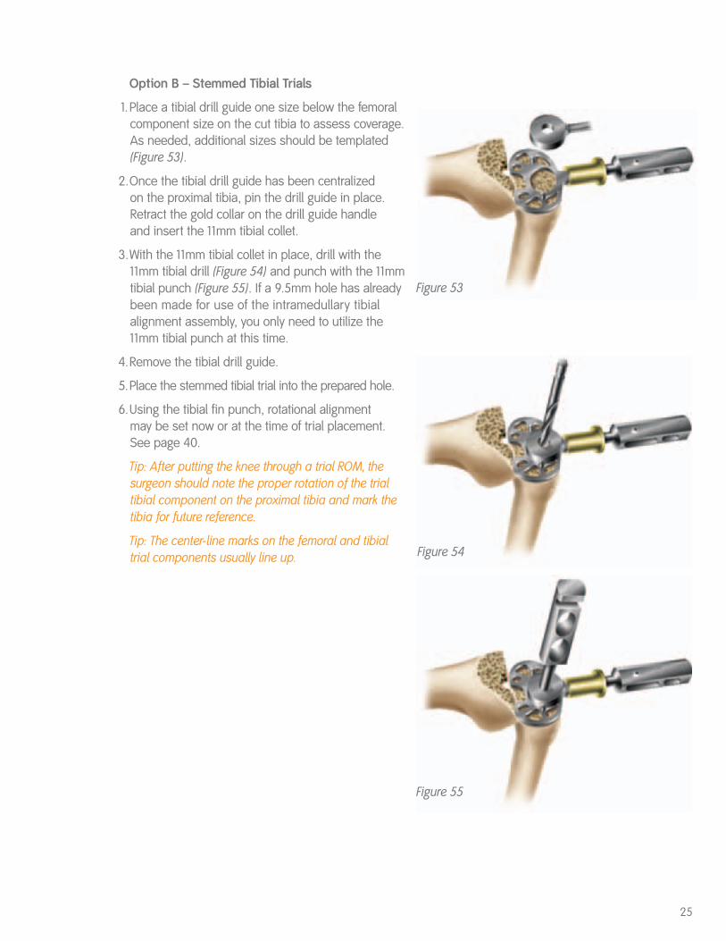
Option B – Stemmed Tibial Trials
1.Place a tibial drill guide one size below the femoralcomponent size on the cut tibia to assess coverage.As needed, additional sizes should be templated(Figure 53).
2.Once the tibial drill guide has been centralized on the proximal tibia, pin the drill guide in place.Retract the gold collar on the drill guide handle and insert the 11mm tibial collet.
3.With the 11mm tibial collet in place, drill with the11mm tibial drill (Figure 54) and punch with the 11mmtibial punch (Figure 55). If a 9.5mm hole has alreadybeen made for use of the intramedullary tibialalignment assembly, you only need to utilize the11mm tibial punch at this time.
4.Remove the tibial drill guide.
5.Place the stemmed tibial trial into the prepared hole.
6.Using the tibial fin punch, rotational alignment may be set now or at the time of trial placement. See page 40.
Tip: After putting the knee through a trial ROM, thesurgeon should note the proper rotation of the trialtibial component on the proximal tibia and mark thetibia for future reference.
Tip: The center-line marks on the femoral and tibialtrial components usually line up.
25
Figure 53
Figure 54
Figure 55
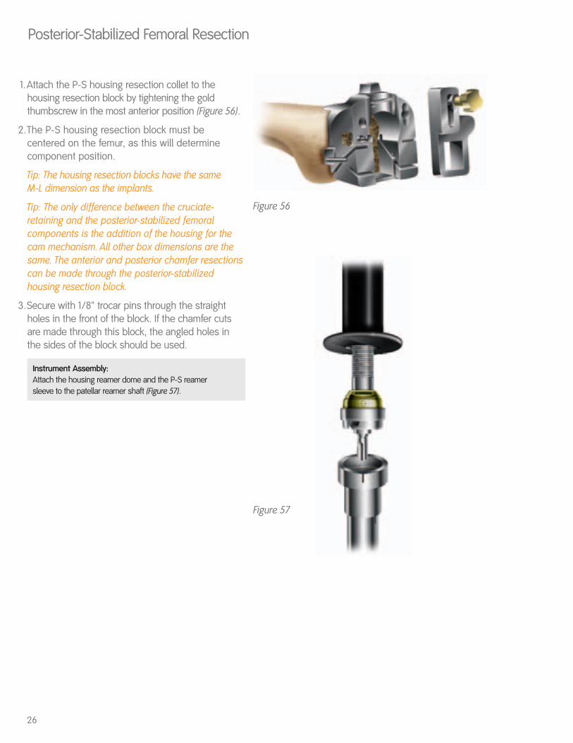
1.Attach the P-S housing resection collet to thehousing resection block by tightening the goldthumbscrew in the most anterior position (Figure 56).
2.The P-S housing resection block must becentered on the femur, as this will determinecomponent position.
Tip: The housing resection blocks have the same M-L dimension as the implants.
Tip: The only difference between the cruciate-retaining and the posterior-stabilized femoralcomponents is the addition of the housing for thecam mechanism. All other box dimensions are thesame. The anterior and posterior chamfer resectionscan be made through the posterior-stabilizedhousing resection block.
3.Secure with 1/8" trocar pins through the straightholes in the front of the block. If the chamfer cutsare made through this block, the angled holes inthe sides of the block should be used.
Instrument Assembly: Attach the housing reamer dome and the P-S reamer sleeve to the patellar reamer shaft (Figure 57).
Posterior-Stabilized Femoral Resection
26
Figure 57
Figure 56
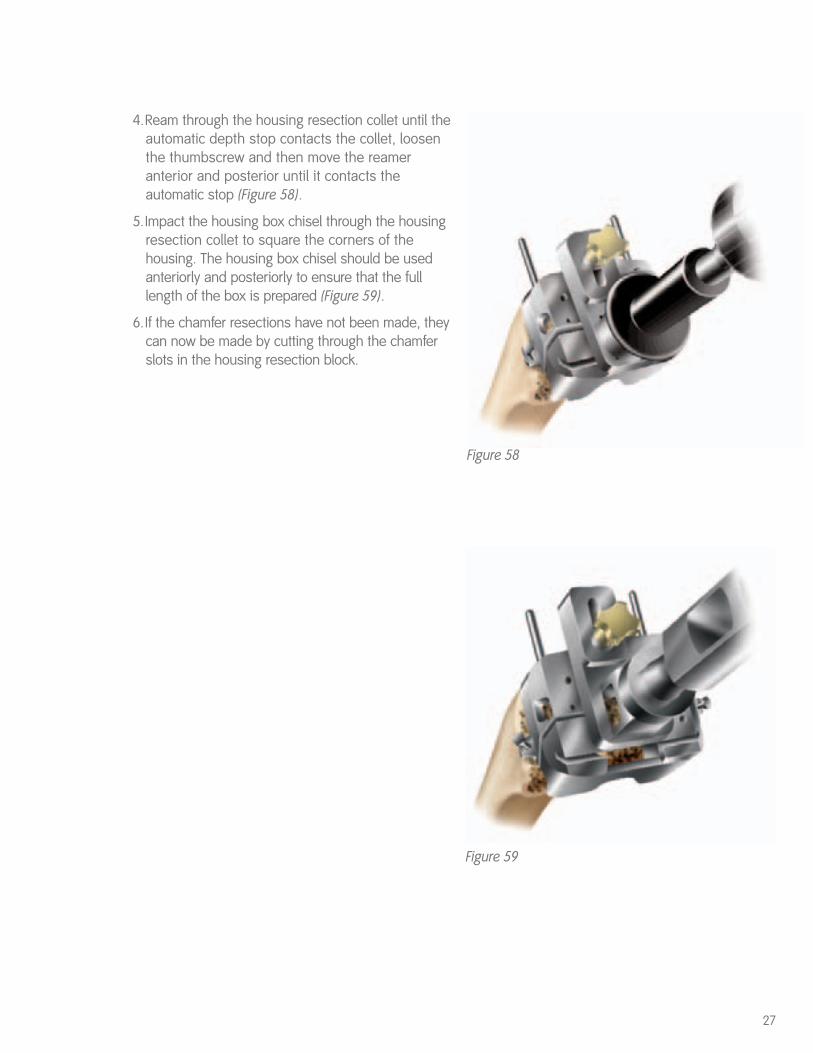
4.Ream through the housing resection collet until theautomatic depth stop contacts the collet, loosenthe thumbscrew and then move the reameranterior and posterior until it contacts theautomatic stop (Figure 58).
5.Impact the housing box chisel through the housingresection collet to square the corners of thehousing. The housing box chisel should be usedanteriorly and posteriorly to ensure that the fulllength of the box is prepared (Figure 59).
6.If the chamfer resections have not been made, theycan now be made by cutting through the chamferslots in the housing resection block.
27
Figure 59
Figure 58
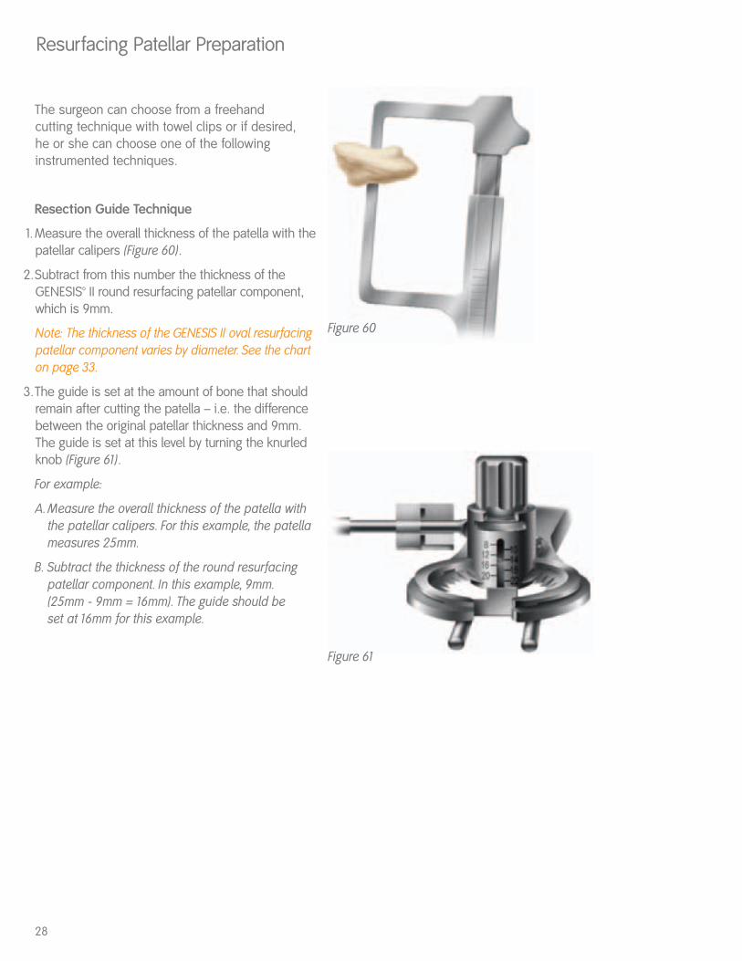
The surgeon can choose from a freehand cutting technique with towel clips or if desired, he or she can choose one of the followinginstrumented techniques.
Resection Guide Technique
1.Measure the overall thickness of the patella with thepatellar calipers (Figure 60).
2.Subtract from this number the thickness of theGENESIS™ II round resurfacing patellar component, which is 9mm.
Note: The thickness of the GENESIS II oval resurfacingpatellar component varies by diameter. See the charton page 33.
3.The guide is set at the amount of bone that shouldremain after cutting the patella – i.e. the differencebetween the original patellar thickness and 9mm.The guide is set at this level by turning the knurledknob (Figure 61).
For example:
A. Measure the overall thickness of the patella withthe patellar calipers. For this example, the patella measures 25mm.
B. Subtract the thickness of the round resurfacing patellar component. In this example, 9mm. (25mm - 9mm = 16mm). The guide should be set at 16mm for this example.
Resurfacing Patellar Preparation
28
Figure 60
Figure 61
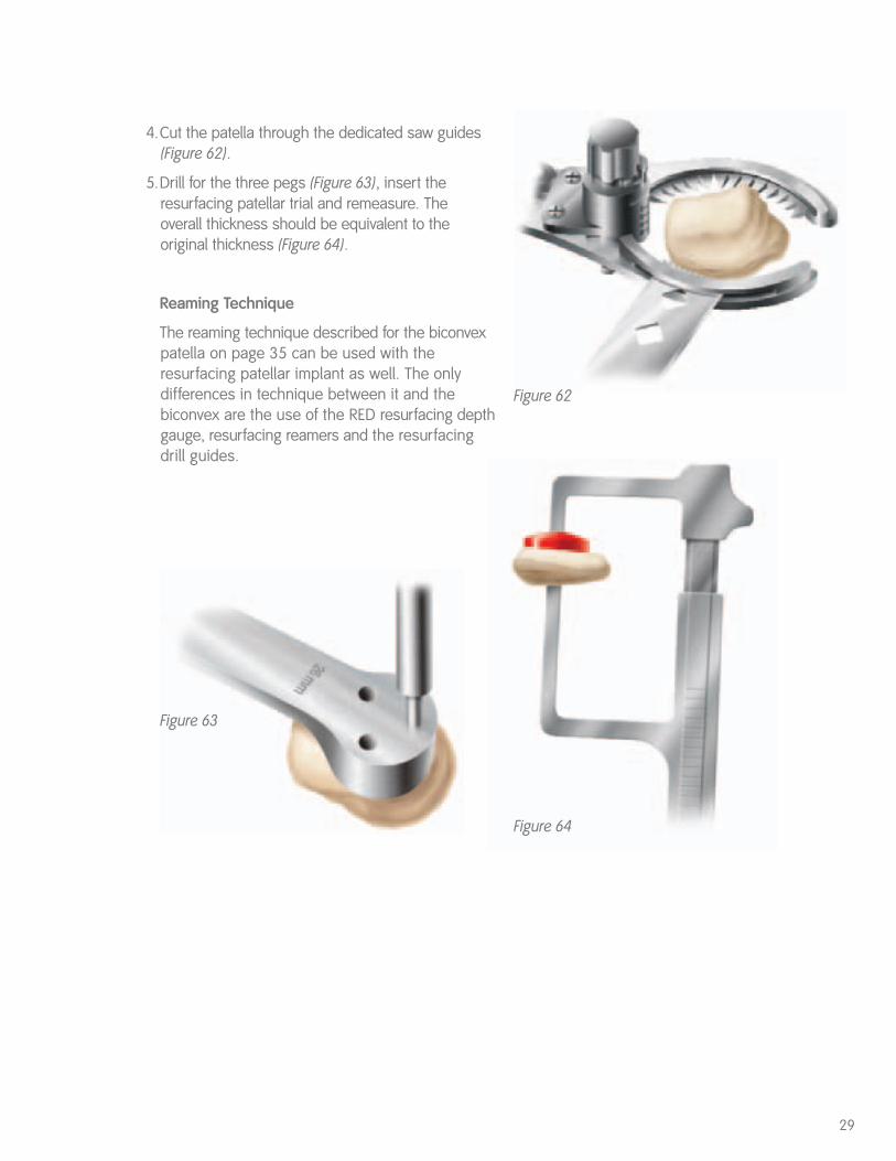
4.Cut the patella through the dedicated saw guides(Figure 62).
5.Drill for the three pegs (Figure 63), insert theresurfacing patellar trial and remeasure. The overall thickness should be equivalent to theoriginal thickness (Figure 64).
Reaming Technique
The reaming technique described for the biconvexpatella on page 35 can be used with theresurfacing patellar implant as well. The onlydifferences in technique between it and thebiconvex are the use of the RED resurfacing depthgauge, resurfacing reamers and the resurfacingdrill guides.
29
Figure 64
Figure 63
Figure 62
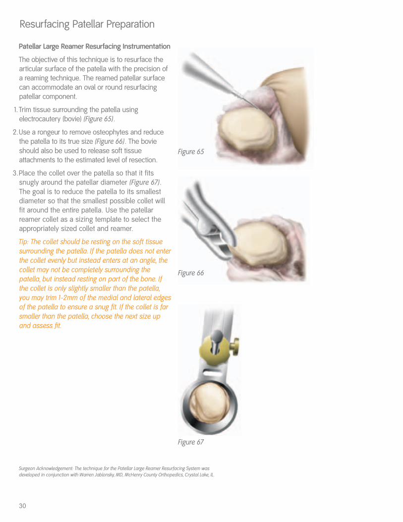
Figure 67
Patellar Large Reamer Resurfacing Instrumentation
The objective of this technique is to resurface thearticular surface of the patella with the precision ofa reaming technique. The reamed patellar surfacecan accommodate an oval or round resurfacingpatellar component.
1.Trim tissue surrounding the patella usingelectrocautery (bovie) (Figure 65).
2.Use a rongeur to remove osteophytes and reducethe patella to its true size (Figure 66). The bovieshould also be used to release soft tissueattachments to the estimated level of resection.
3.Place the collet over the patella so that it fitssnugly around the patellar diameter (Figure 67).The goal is to reduce the patella to its smallestdiameter so that the smallest possible collet willfit around the entire patella. Use the patellarreamer collet as a sizing template to select theappropriately sized collet and reamer.
Tip: The collet should be resting on the soft tissuesurrounding the patella. If the patella does not enterthe collet evenly but instead enters at an angle, thecollet may not be completely surrounding thepatella, but instead resting on part of the bone. Ifthe collet is only slightly smaller than the patella,you may trim 1-2mm of the medial and lateral edgesof the patella to ensure a snug fit. If the collet is farsmaller than the patella, choose the next size upand assess fit.
Resurfacing Patellar Preparation
30
Surgeon Acknowledgement: The technique for the Patellar Large Reamer Resurfacing System wasdeveloped in conjunction with Warren Jablonsky, MD, McHenry County Orthopedics, Crystal Lake, IL.
Figure 65
Figure 66
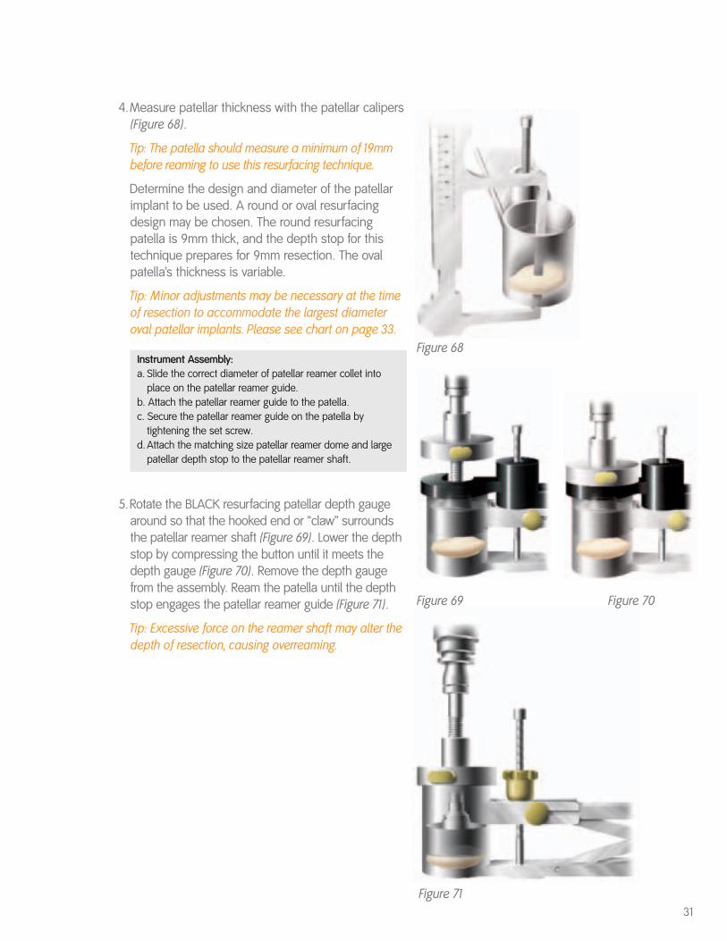
4.Measure patellar thickness with the patellar calipers(Figure 68).
Tip: The patella should measure a minimum of 19mmbefore reaming to use this resurfacing technique.
Determine the design and diameter of the patellarimplant to be used. A round or oval resurfacingdesign may be chosen. The round resurfacingpatella is 9mm thick, and the depth stop for thistechnique prepares for 9mm resection. The ovalpatella’s thickness is variable.
Tip: Minor adjustments may be necessary at the timeof resection to accommodate the largest diameteroval patellar implants. Please see chart on page 33.
Instrument Assembly:a. Slide the correct diameter of patellar reamer collet into
place on the patellar reamer guide. b. Attach the patellar reamer guide to the patella. c. Secure the patellar reamer guide on the patella by
tightening the set screw.d. Attach the matching size patellar reamer dome and large
patellar depth stop to the patellar reamer shaft.
5.Rotate the BLACK resurfacing patellar depth gaugearound so that the hooked end or “claw” surroundsthe patellar reamer shaft (Figure 69). Lower the depthstop by compressing the button until it meets thedepth gauge (Figure 70). Remove the depth gaugefrom the assembly. Ream the patella until the depthstop engages the patellar reamer guide (Figure 71).
Tip: Excessive force on the reamer shaft may alter thedepth of resection, causing overreaming.
31
Figure 69 Figure 70
Figure 71
Figure 68
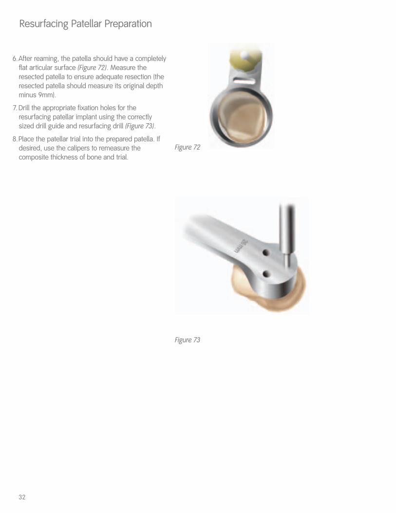
6.After reaming, the patella should have a completelyflat articular surface (Figure 72). Measure theresected patella to ensure adequate resection (theresected patella should measure its original depthminus 9mm).
7. Drill the appropriate fixation holes for theresurfacing patellar implant using the correctlysized drill guide and resurfacing drill (Figure 73).
8.Place the patellar trial into the prepared patella. Ifdesired, use the calipers to remeasure thecomposite thickness of bone and trial.
Resurfacing Patellar Preparation
32
Figure 72
Figure 73
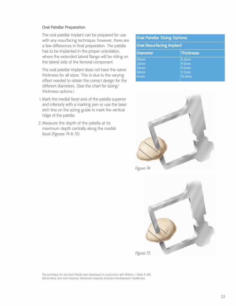
Oval Patellar Preparation
The oval patellar implant can be prepared for usewith any resurfacing technique; however, there area few differences in final preparation. The patellahas to be implanted in the proper orientation,where the extended lateral flange will be riding onthe lateral side of the femoral component.
The oval patellar implant does not have the samethickness for all sizes. This is due to the varyingoffset needed to obtain the correct design for thedifferent diameters. (See the chart for sizing/thickness options.)
1.Mark the medial facet axis of the patella superiorand inferiorly with a marking pen or use the laseretch line on the sizing guide to mark the verticalridge of the patella.
2.Measure the depth of the patella at its maximum depth centrally along the medial facet (Figures 74 & 75).
33
Oval Patellar Sizing Options
Oval Resurfacing Implant
Diameter Thickness29mm32mm35mm38mm41mm
8.5mm9.0mm9.0mm9.5mm10.0mm
Figure 74
Figure 75
The technique for the Oval Patella was developed in conjunction with William J. Robb III, MD,Illinois Bone and Joint Institute, Glenbrook Hospital, Evanston Northwestern Healthcare.
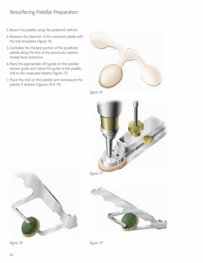
Figure 79Figure 78
3.Resect the patella using the preferred method.
4.Measure the diameter of the resected patella withthe trial templates (Figure 76).
5.Centralize the thickest portion of the prostheticpatella along the line of the previously markedmedial facet eminence.
6.Place the appropriate drill guide on the patellarreamer guide and clamp the guide to the patella.Drill to the measured depths (Figure 77).
7. Place the trial on the patella and remeasure thepatella if desired (Figures 78 & 79).
Resurfacing Patellar Preparation
Figure 76
Figure 77
34
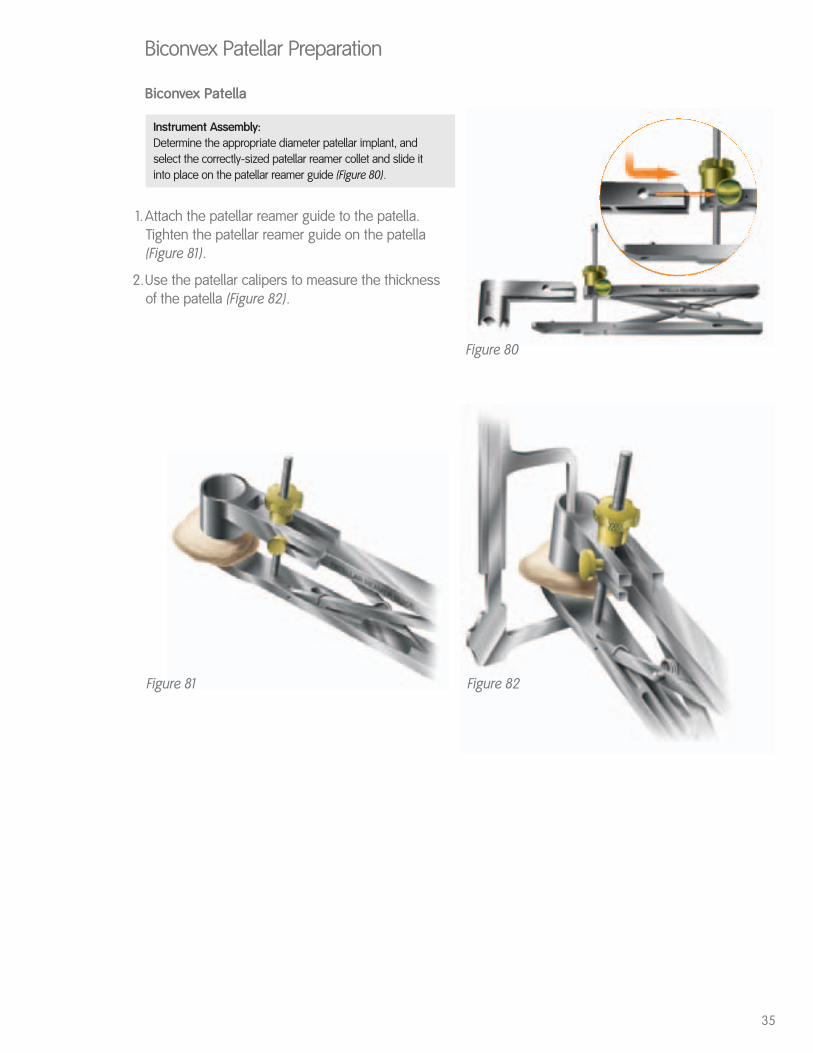
Biconvex Patella
Instrument Assembly: Determine the appropriate diameter patellar implant, and select the correctly-sized patellar reamer collet and slide it into place on the patellar reamer guide (Figure 80).
1.Attach the patellar reamer guide to the patella.Tighten the patellar reamer guide on the patella(Figure 81).
2.Use the patellar calipers to measure the thicknessof the patella (Figure 82).
Biconvex Patellar Preparation
Figure 81 Figure 82
Figure 80
35
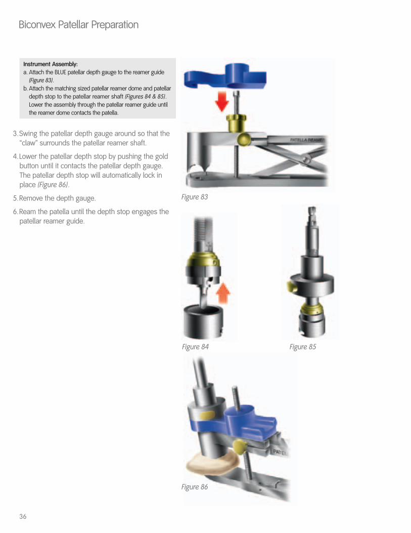
Figure 86
Figure 84 Figure 85
Instrument Assembly:a. Attach the BLUE patellar depth gauge to the reamer guide
(Figure 83). b. Attach the matching sized patellar reamer dome and patellar
depth stop to the patellar reamer shaft (Figures 84 & 85).Lower the assembly through the patellar reamer guide until the reamer dome contacts the patella.
3.Swing the patellar depth gauge around so that the“claw” surrounds the patellar reamer shaft.
4.Lower the patellar depth stop by pushing the goldbutton until it contacts the patellar depth gauge.The patellar depth stop will automatically lock inplace (Figure 86).
5.Remove the depth gauge.
6.Ream the patella until the depth stop engages thepatellar reamer guide.
Biconvex Patellar Preparation
36
Figure 83
Component Trialing
Figure 87
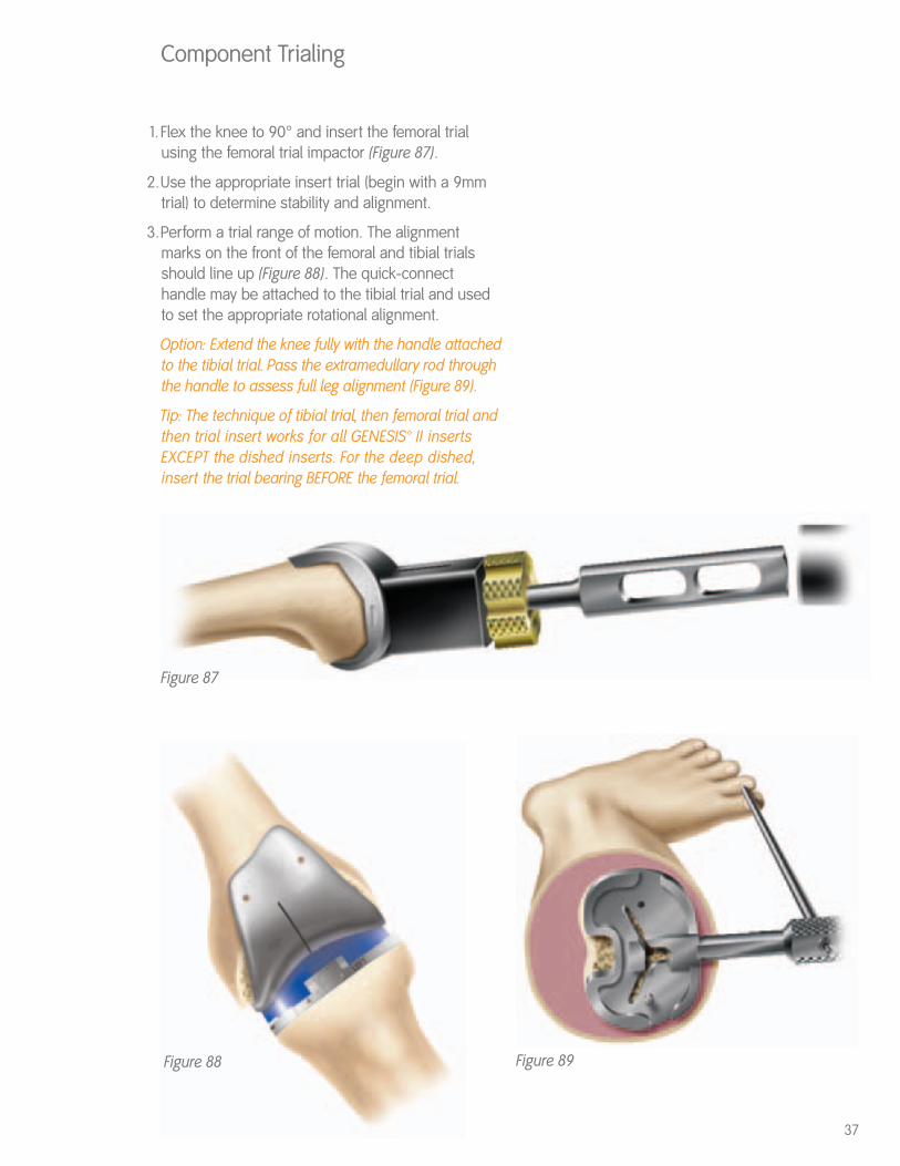
1. Flex the knee to 90° and insert the femoral trialusing the femoral trial impactor (Figure 87).
2.Use the appropriate insert trial (begin with a 9mmtrial) to determine stability and alignment.
3.Perform a trial range of motion. The alignmentmarks on the front of the femoral and tibial trialsshould line up (Figure 88). The quick-connecthandle may be attached to the tibial trial and usedto set the appropriate rotational alignment.
Option: Extend the knee fully with the handle attachedto the tibial trial. Pass the extramedullary rod throughthe handle to assess full leg alignment (Figure 89).
Tip: The technique of tibial trial, then femoral trial andthen trial insert works for all GENESIS™ II insertsEXCEPT the dished inserts. For the deep dished,insert the trial bearing BEFORE the femoral trial.
Figure 88 Figure 89
37
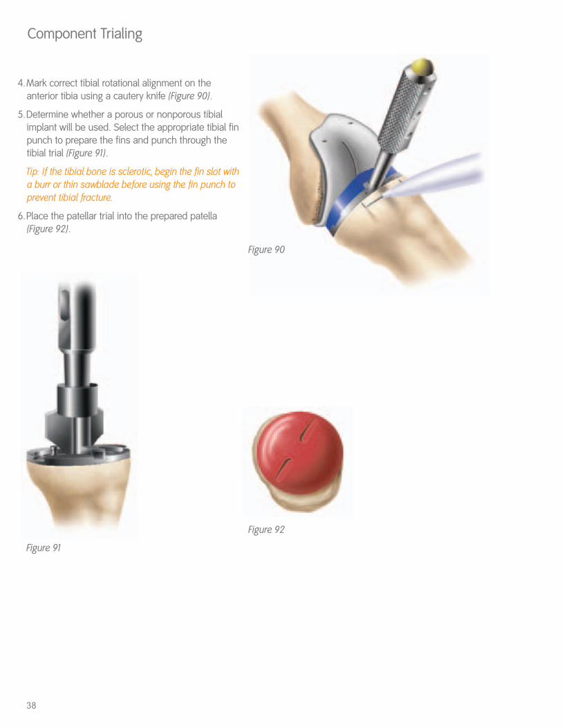
4.Mark correct tibial rotational alignment on theanterior tibia using a cautery knife (Figure 90).
5.Determine whether a porous or nonporous tibialimplant will be used. Select the appropriate tibial finpunch to prepare the fins and punch through thetibial trial (Figure 91).
Tip: If the tibial bone is sclerotic, begin the fin slot witha burr or thin sawblade before using the fin punch toprevent tibial fracture.
6.Place the patellar trial into the prepared patella(Figure 92).
Component Trialing
38
Figure 91
Figure 90
Figure 92
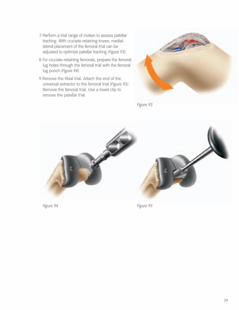
7. Perform a trial range of motion to assess patellartracking. With cruciate-retaining knees, medial-lateral placement of the femoral trial can beadjusted to optimize patellar tracking (Figure 93).
8.For cruciate-retaining femorals, prepare the femorallug holes through the femoral trial with the femorallug punch (Figure 94).
9.Remove the tibial trial. Attach the end of theuniversal extractor to the femoral trial (Figure 95).Remove the femoral trial. Use a towel clip toremove the patellar trial.
39
Figure 95Figure 94
Figure 93
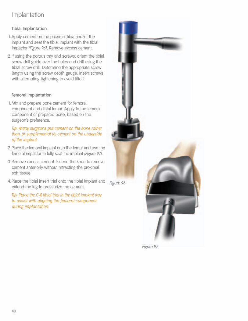
Tibial Implantation
1.Apply cement on the proximal tibia and/or theimplant and seat the tibial implant with the tibialimpactor (Figure 96). Remove excess cement.
2.If using the porous tray and screws, orient the tibialscrew drill guide over the holes and drill using thetibial screw drill. Determine the appropriate screwlength using the screw depth gauge. Insert screwswith alternating tightening to avoid liftoff.
Femoral Implantation
1.Mix and prepare bone cement for femoralcomponent and distal femur. Apply to the femoralcomponent or prepared bone, based on thesurgeon’s preference.
Tip: Many surgeons put cement on the bone ratherthan, or supplemental to, cement on the undersideof the implant.
2.Place the femoral implant onto the femur and use thefemoral impactor to fully seat the implant (Figure 97).
3.Remove excess cement. Extend the knee to removecement anteriorly without retracting the proximalsoft tissue.
4.Place the tibial insert trial onto the tibial implant andextend the leg to pressurize the cement.
Tip: Place the C-R tibial trial in the tibial implant trayto assist with aligning the femoral componentduring implantation.
Implantation
40
Figure 96
Figure 97
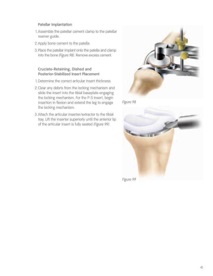
Patellar Implantation
1.Assemble the patellar cement clamp to the patellarreamer guide.
2.Apply bone cement to the patella.
3.Place the patellar implant onto the patella and clampinto the bone (Figure 98). Remove excess cement.
Cruciate-Retaining, Dished and Posterior-Stabilized Insert Placement
1.Determine the correct articular insert thickness.
2.Clear any debris from the locking mechanism andslide the insert into the tibial baseplate engagingthe locking mechanism. For the P-S insert, begininsertion in flexion and extend the leg to engagethe locking mechanism.
3.Attach the articular inserter/extractor to the tibialtray. Lift the inserter superiorly until the anterior lipof the articular insert is fully seated (Figure 99).
41
Figure 99
Figure 98
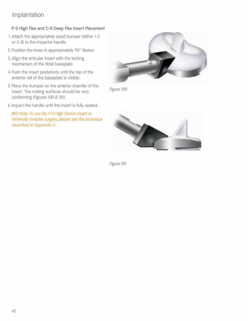
P-S High Flex and C-R Deep Flex Insert Placement
1.Attach the appropriately sized bumper (either 1-2 or 3-8) to the impactor handle.
2.Position the knee in approximately 90° flexion.
3.Align the articular insert with the lockingmechanism of the tibial baseplate.
4.Push the insert posteriorly until the top of theanterior rail of the baseplate is visible.
5.Place the bumper on the anterior chamfer of theinsert. The mating surfaces should be veryconforming (Figures 100 & 101).
6.Impact the handle until the insert is fully seated.
MIS Note: To use the P-S High Flexion Insert inminimally invasive surgery, please see the techniquedescribed in Appendix A.
Implantation
Figure 100
Figure 101
42
43For clinical evaluation only. Not for distribution.
Appendix AGENESIS™ II P-S High Flex Insert Impaction Technique for MIS
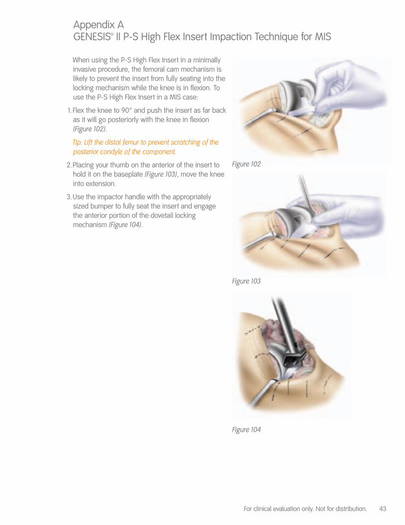
When using the P-S High Flex Insert in a minimallyinvasive procedure, the femoral cam mechanism islikely to prevent the insert from fully seating into thelocking mechanism while the knee is in flexion. Touse the P-S High Flex Insert in a MIS case:
1. Flex the knee to 90° and push the insert as far backas it will go posteriorly with the knee in flexion(Figure 102).
Tip: Lift the distal femur to prevent scratching of theposterior condyle of the component.
2.Placing your thumb on the anterior of the insert tohold it on the baseplate (Figure 103), move the kneeinto extension.
3.Use the impactor handle with the appropriatelysized bumper to fully seat the insert and engagethe anterior portion of the dovetail lockingmechanism (Figure 104).
Figure 102
Figure 103
Figure 104
44
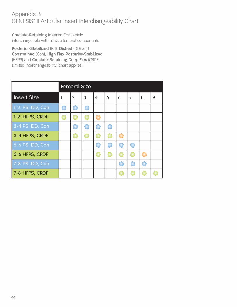
Cruciate-Retaining Inserts: Completelyinterchangeable with all size femoral components
Posterior-Stabilized (PS), Dished (DD) andConstrained (Con), High Flex Posterior-Stabilized(HFPS) and Cruciate-Retaining Deep Flex (CRDF): Limited interchangeability; chart applies.
Appendix BGENESIS™ II Articular Insert Interchangeability Chart
Femoral Size
Insert Size 1 2 3 4 5 6 7 8 9
1-2 PS, DD, Con
1-2 HFPS, CRDF
3-4 PS, DD, Con
3-4 HFPS, CRDF
5-6 PS, DD, Con
5-6 HFPS, CRDF
7-8 PS, DD, Con
7-8 HFPS, CRDF

45


™Trademark of Smith & Nephew. Registered US Patent and Trademark Office.
OrthopaedicsSmith & Nephew, Inc.1450 Brooks RoadMemphis, TN 38116USA
Telephone: 1-901-396-2121Information: 1-800-821-5700Orders/Inquiries: 1-800-238-7538
40420114 7128-1337 01/06
www.smith-nephew.comwww.miknee.com