genius 1022, 1023 & nm32la (all models) - peak industrial · genius1022-1023-nm32la user manual...
TRANSCRIPT
Genius1022-1023-NM32LA User Manual Rev 2 PN UM-0001 29/07/16
Genius 1022, 1023 & NM32LA (All Models) User Manual
Contents
User Manual 1
Change History 3
How to use this Manual 3
Introduction 4
Warranties and Liabilities 5
Safety Notices 6
Symbols 6
Safety Notice to Users 6
Declaration of Conformity 7
Environmental Declaration 8
Technical Specification 9
Unpacking 13
Fittings Kit Contents 14
Installation 15
Generator Environment 15
Generator Overview 16
General Dimensions 16
Rear Connections 17
Unit Controls 17
Drain Connection 18
Electrical Connection 19
Start-Up Sequence 20
Connecting to the application 21
Tubing Lengths 21
Normal Operation 22
Normal Operation - Genius 1023 22
On Demand Gas 22
Generator Cycling 23
Unusual Operation 23
Service Requirements 24
Service Schedule 24
Service Indication 25
Peak Protected 26
Cleaning 27
High Duty Indication 28
High Duty Indication Reset 28
Indication of Fault 28
Troubleshooting 29
Page 2

Page 3
Change History
Rev Comment Name Date
How to use this Manual
This manual is intended for end users and has been written as a reference document where you can skip to the relevant information.
Users can refer to the contents page to find the relevant information.
Please review each of the following sections carefully.
Thank you for selecting Peak Scientific to meet your gas generation needs, and should you require any further assistance or support please do not hesitate to contact Peak Scientific or the Peak Partner from which you purchased your generator.
Page 4
Introduction
The Genius 1022, 1023 & NM32LA (All models) have been developed to cater for LC/MS systems which require a Nitrogen gas supply.
These models provide a source of Nitrogen gas with other features including:
• Small in size – fits under a standard lab bench
• Anti- vibration – maximum reduction of vibration
• Service indication – allowing you to plan your maintenance and keep your application uptime at a maximum
• Improved drainage – reduction of moisture carry over and thus increased reliability
• Re- heat technology – improves membrane performance and reliability
• Robust control system – improves safety and reliability of units
With the generators based on proven technology, they selectively remove oxygen, moisture and other gases to leave clean, dry, phthalate free Nitrogen. Two internal air compressors make these units independent from in- house air supplies and fitted castors allow the user to easily position the units in the lab.
To ensure the Generator models meet our high expectations with regards to reliability and performance, we have tested them extensively at our manufacturing plant and with end users around the world to ensure reliability and longevity of the system.
Page 5
Warranties and Liabilities1. The Company warrants that it has title to the Goods.
2. Subject to the provisions of this clause the Company warrants that the Goods shall comply in all material respects with any specification referred to in the Order Confirmation (as the same may be amended) and shall, subject thereto, be free from defects in material and workmanship for the lesser of a period of twelve months from the date of delivery or thirteen months from the date of dispatch from the factory.
3. Save as provided in this clause and except where the Goods are sold to a person dealing as a consumer (within the meaning of the Unfair Contract Terms Act 1977) all warranties, conditions or other terms implied by statute or common law are hereby expressly excluded save to the extent they may not be lawfully excluded. When the Goods are sold to a consumer within the meaning of the Unfair Contract Terms Act 1977 their statutory rights are not affected by the provisions of this clause.
4. In the event of the Customer making a claim in respect of any defect in terms of clause 2 hereof the Customer must. 1. Reasonably satisfy the Company that the Goods have been properly installed, commissioned, stored, serviced and used and without prejudice to the generality of the foregoing that any defect is not the direct or indirect result of lack of repair and/or servicing, incorrect repair and/or servicing, use of wrong materials and/or incorrect spare parts 2. Allow the company to inspect the Goods and/or any installation and any relevant packaging as and when reasonably required by the Company.
5. Subject to the Company being notified of any defect as is referred to in sub- clause 2 hereof within a reasonable time of it becoming apparent and subject always to the terms of sub-clause 4 hereof, the Company shall, in its option, replace or repair the defective Goods or refund a proportionate part of the Price. The Company shall have no further liability to the Customer (save as mentioned in sub-clause 6 hereof).
6. The Company shall be liable to indemnify the Customer in respect of any claim for death or personal injury to any person in so far as such is attributable to the negligence or breach of duty of the Company or any failure by the Company to comply with the provisions of sub-clause 2 hereof.
7. Save as provided in sub-clause 2 hereof the Company shall not be liable in respect of any claim by the Customer for costs, damages, loss or expenses (whether direct, indirect, consequential or otherwise) or indemnity in any respect howsoever arising including, but not by way of limitation, liability arising in negligence (other than pursuant to clause 6 above) that may be suffered by the Customer or any third party.
WARNING
WARNING
WARNING
WARNING
CAUTION
Page 6
Safety NoticesPeak Scientific Instruments cannot anticipate every possible circumstance which may represent a potential hazard. The warnings detailed within this manual refer to the most likely potential hazards, but by definition cannot be all inclusive. If the user employs an operating procedure, item of equipment or a method of working which is not specifically recommended by Peak Scientific, the user must ensure that the equipment will not be damaged or become hazardous to persons or property.
Symbols
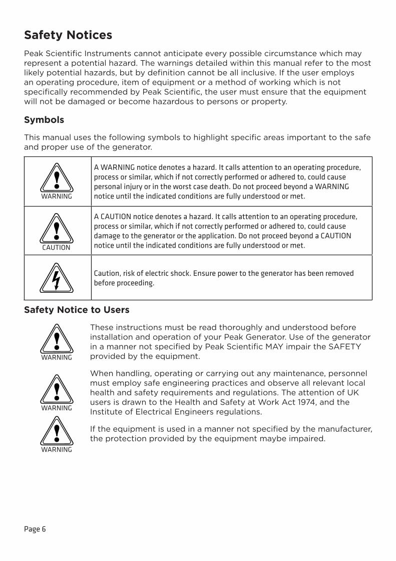
This manual uses the following symbols to highlight specific areas important to the safe and proper use of the generator.
A WARNING notice denotes a hazard. It calls attention to an operating procedure, process or similar, which if not correctly performed or adhered to, could cause personal injury or in the worst case death. Do not proceed beyond a WARNING notice until the indicated conditions are fully understood or met.
A CAUTION notice denotes a hazard. It calls attention to an operating procedure, process or similar, which if not correctly performed or adhered to, could cause damage to the generator or the application. Do not proceed beyond a CAUTION notice until the indicated conditions are fully understood or met.
Caution, risk of electric shock. Ensure power to the generator has been removed before proceeding.
Safety Notice to Users
These instructions must be read thoroughly and understood before installation and operation of your Peak Generator. Use of the generator in a manner not specified by Peak Scientific MAY impair the SAFETY provided by the equipment.
When handling, operating or carrying out any maintenance, personnel must employ safe engineering practices and observe all relevant local health and safety requirements and regulations. The attention of UK users is drawn to the Health and Safety at Work Act 1974, and the Institute of Electrical Engineers regulations.
If the equipment is used in a manner not specified by the manufacturer, the protection provided by the equipment maybe impaired.

Page 7
Declaration of Conformity
We Peak Scientifi c Instruments Ltd.
Of Fountain Crescent, Inchinnan, Renfrewshire, PA4 9RE
Declare that:
Equipment: Nitrogen Generator
Models: Genius 1022, 1023, NM32LA, NM32LA 110V & NM32LA-A
To which this declaration relates, is in conformity with the applicable EC directives, harmonized standards, and other normative requirements.
• Low Voltage Directive 2014/35/EUEN 61010-1: 2010 Electrical Equipment for measurement, control and laboratory use.
• Electromagnetic Compatibility Directive 2014/30/EUEN 61326-1: 2013 Electrical Equipment for measurement, control and laboratory use.
• FCC47 CFR Part 15 Class BUnintentional radiators; Conducted and Radiated emissions limits.
All evaluation, testing and certifi cation issued by:
Nemko Canada Inc.
303 River Road, Ottawa
Ontario, Canada
K1V 1H2
Signed: Name: Chris Pugh
Date: 16/05/2016 Position: Engineering & Operations Director
Page 8
Environmental Declaration
We Peak Scientifi c Instruments Ltd.
Of Fountain Crescent, Inchinnan, Renfrewshire, PA4 9RE
Declare that:
Equipment: Nitrogen Generator
Models: Genius 1022, 1023, NM32LA (All Models)
Is fully compliant with the following Directives
• 2012/19/EU WEEE (Waste of Electrical and Electronic Equipment)
• 2011/65/EU RoHS 2 (Restriction of Hazardous Substance)
Peak Scientifi c Instruments Ltd fully complies with its obligations towards the European WEEE (Waste of Electrical and Electronic Equipment) Directive 2012/19/EU. These obligations are being met within the B2B compliance group.
Peak Scientifi c Instruments Ltd has developed all reasonable ‘due diligence’ controls to ensure that our products comply with the principles and requirements of the European recast RoHS (Restriction of Hazardous Substances) Directive 2011/65/EU. Similar directives in the United States and China, for example, have also been captured within this program.
Where a specifi c certifi cate of compliance is required, this can be requested, on a product serial number basis, directly from Peak Scientifi c Instruments Ltd, by contacting us through our website on www.peakscientifi c.com
Signed: Name: Chris Pugh
Date: 16/05/2016 Position: Engineering & Operations Director
Page 9
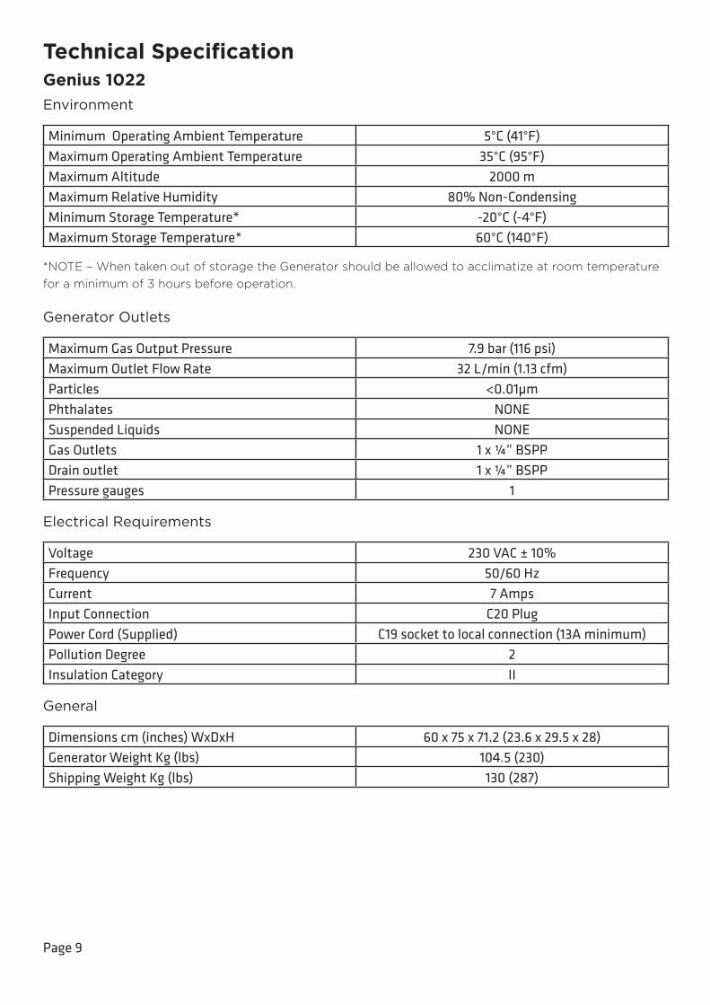
Technical SpecificationGenius 1022Environment
Minimum Operating Ambient Temperature 5°C (41°F)Maximum Operating Ambient Temperature 35°C (95°F)Maximum Altitude 2000 mMaximum Relative Humidity 80% Non-CondensingMinimum Storage Temperature* -20°C (-4°F)Maximum Storage Temperature* 60°C (140°F)
*NOTE – When taken out of storage the Generator should be allowed to acclimatize at room temperature for a minimum of 3 hours before operation.
Generator Outlets
Maximum Gas Output Pressure 7.9 bar (116 psi)Maximum Outlet Flow Rate 32 L/min (1.13 cfm)Particles <0.01µmPhthalates NONESuspended Liquids NONEGas Outlets 1 x ¼” BSPPDrain outlet 1 x ¼” BSPPPressure gauges 1
Electrical Requirements
Voltage 230 VAC ± 10%Frequency 50/60 HzCurrent 7 AmpsInput Connection C20 PlugPower Cord (Supplied) C19 socket to local connection (13A minimum)Pollution Degree 2Insulation Category II
General
Dimensions cm (inches) WxDxH 60 x 75 x 71.2 (23.6 x 29.5 x 28)Generator Weight Kg (lbs) 104.5 (230)Shipping Weight Kg (lbs) 130 (287)
Page 10
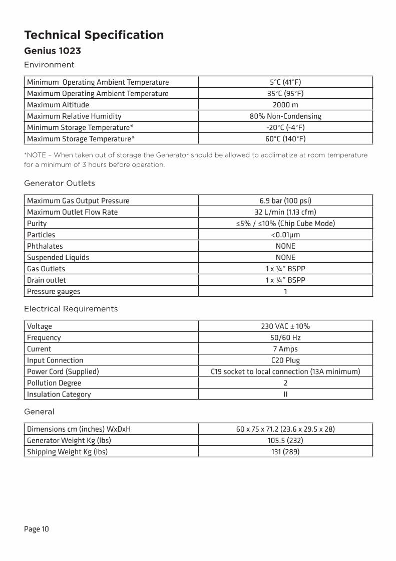
Technical SpecificationGenius 1023Environment
Minimum Operating Ambient Temperature 5°C (41°F)Maximum Operating Ambient Temperature 35°C (95°F)Maximum Altitude 2000 mMaximum Relative Humidity 80% Non-CondensingMinimum Storage Temperature* -20°C (-4°F)Maximum Storage Temperature* 60°C (140°F)
*NOTE – When taken out of storage the Generator should be allowed to acclimatize at room temperature for a minimum of 3 hours before operation.
Generator Outlets
Maximum Gas Output Pressure 6.9 bar (100 psi)Maximum Outlet Flow Rate 32 L/min (1.13 cfm)Purity ≤5% / ≤10% (Chip Cube Mode)Particles <0.01µmPhthalates NONESuspended Liquids NONEGas Outlets 1 x ¼” BSPPDrain outlet 1 x ¼” BSPPPressure gauges 1
Electrical Requirements
Voltage 230 VAC ± 10%Frequency 50/60 HzCurrent 7 AmpsInput Connection C20 PlugPower Cord (Supplied) C19 socket to local connection (13A minimum)Pollution Degree 2Insulation Category II
General
Dimensions cm (inches) WxDxH 60 x 75 x 71.2 (23.6 x 29.5 x 28)Generator Weight Kg (lbs) 105.5 (232)Shipping Weight Kg (lbs) 131 (289)
Page 11
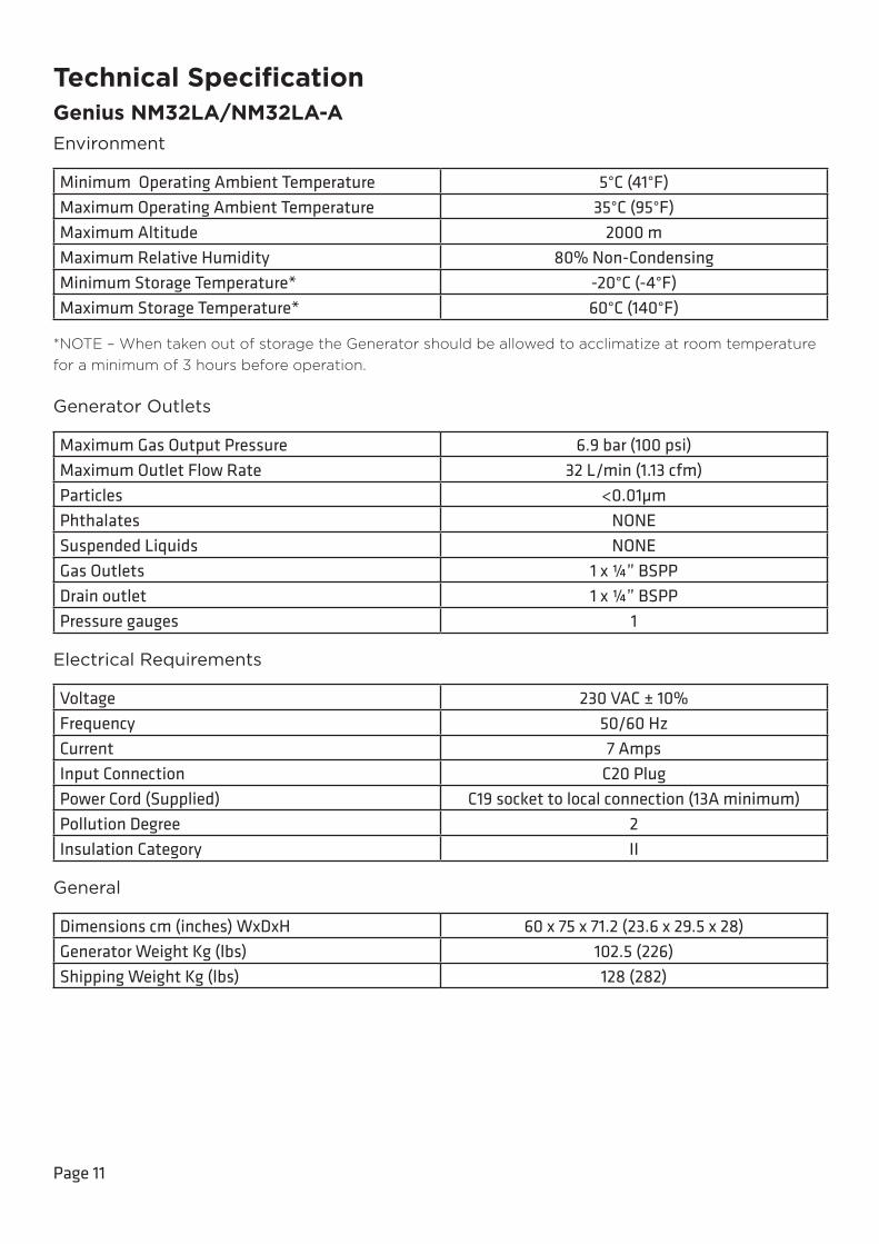
Technical SpecificationGenius NM32LA/NM32LA-AEnvironment
Minimum Operating Ambient Temperature 5°C (41°F)Maximum Operating Ambient Temperature 35°C (95°F)Maximum Altitude 2000 mMaximum Relative Humidity 80% Non-CondensingMinimum Storage Temperature* -20°C (-4°F)Maximum Storage Temperature* 60°C (140°F)
*NOTE – When taken out of storage the Generator should be allowed to acclimatize at room temperature for a minimum of 3 hours before operation.
Generator Outlets
Maximum Gas Output Pressure 6.9 bar (100 psi)Maximum Outlet Flow Rate 32 L/min (1.13 cfm)Particles <0.01µmPhthalates NONESuspended Liquids NONEGas Outlets 1 x ¼” BSPPDrain outlet 1 x ¼” BSPPPressure gauges 1
Electrical Requirements
Voltage 230 VAC ± 10%Frequency 50/60 HzCurrent 7 AmpsInput Connection C20 PlugPower Cord (Supplied) C19 socket to local connection (13A minimum)Pollution Degree 2Insulation Category II
General
Dimensions cm (inches) WxDxH 60 x 75 x 71.2 (23.6 x 29.5 x 28)Generator Weight Kg (lbs) 102.5 (226)Shipping Weight Kg (lbs) 128 (282)

Page 12
Technical SpecificationGenius NM32LA 110VEnvironment
Minimum Operating Ambient Temperature 5°C (41°F)Maximum Operating Ambient Temperature 35°C (95°F)Maximum Altitude 2000 mMaximum Relative Humidity 80% Non-CondensingMinimum Storage Temperature* -20°C (-4°F)Maximum Storage Temperature* 60°C (140°F)
*NOTE – When taken out of storage the Generator should be allowed to acclimatize at room temperature for a minimum of 3 hours before operation.
Generator Outlets
Maximum Gas Output Pressure 6.9 bar (100 psi)Maximum Outlet Flow Rate 32 L/min (1.13 cfm)Particles <0.01µmPhthalates NONESuspended Liquids NONEGas Outlets 1 x ¼” BSPPDrain outlet 1 x ¼” BSPPPressure gauges 1
Electrical Requirements
Voltage 115 VAC ± 10%Frequency 60 HzCurrent 11 AmpsInput Connection C20 PlugPower Cord (Supplied) C19 socket to local connection (13A minimum)Pollution Degree 2Insulation Category II
General
Dimensions cm (inches) WxDxH 60 x 75 x 71.2 (23.6 x 29.5 x 28)Generator Weight Kg (lbs) 95 (209)Shipping Weight Kg (lbs) 150 (330)
Page 13
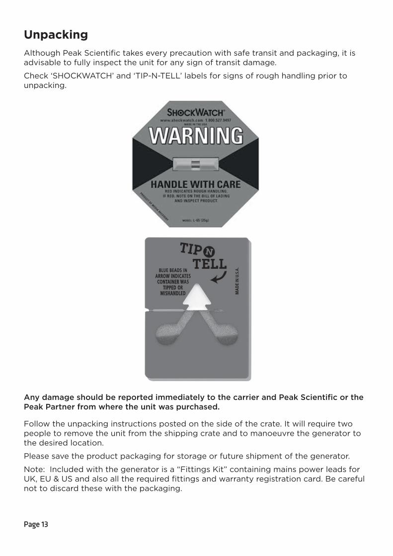
UnpackingAlthough Peak Scientific takes every precaution with safe transit and packaging, it is advisable to fully inspect the unit for any sign of transit damage.
Check ‘SHOCKWATCH’ and ‘TIP-N-TELL’ labels for signs of rough handling prior to unpacking.
Any damage should be reported immediately to the carrier and Peak Scientific or the Peak Partner from where the unit was purchased.
Follow the unpacking instructions posted on the side of the crate. It will require two people to remove the unit from the shipping crate and to manoeuvre the generator to the desired location.
Please save the product packaging for storage or future shipment of the generator.
Note: Included with the generator is a “Fittings Kit” containing mains power leads for UK, EU & US and also all the required fittings and warranty registration card. Be careful not to discard these with the packaging.
Page 13
Page 14
Fittings Kit ContentsSupplied in the Fittings Kit are all the fittings required to connect the generator to the application. The contents of the Fittings Kit are as follows:
1. 6mm Teflon Tubing x 3m
2. ¼” Teflon Tubing x 3m
3. 6mm PE Tubing x 3m
4. ¼” Compression Fitting x 1
5. 6mm Push-Fit Fitting x 2
6. Flow Control Silencer x 1
7. 8mm Hex Key x 1
8. UK Mains Power Cable* x 1
9. EU Mains Power Cable* x 1
10. US Mains Power Cable 110v ** x 1
11. US Mains Power Cable 230v* x 1
All of the generators output ports are located on the output panel at the rear of the unit.
* Genius 1022, 1023 and NM32LA Only
** NM32LA 110V Only
Page 15
Installation
Generator Environment
The generator is designed for indoor use only. It should be installed adjacent to the application(s) it is supplying. If this is not convenient then the unit can be sited elsewhere, however, consideration should be made of the lengths of pipe runs as pressure drops can result from extended runs of pipe.
Performance of the generator (like all sophisticated equipment) is affected by ambient conditions. Note should also be taken to the proximity of Air Conditioning outlets. These can sometimes give rise to “pockets” of air with high relative humidity. Operation of the unit within such a pocket could adversely affect its performance. Consideration should also be given to the air flow around the unit. It is recommended that an air gap of 75mm (3”) should be maintained down both sides and at the rear of the unit. Please refer to the drawing below for the general dimensions of the unit.
Minimum Operating Ambient Temperature: 5 °C (41 °F)
Maximum Operating Ambient Temperature: 35 °C (95 °F)
Page 16
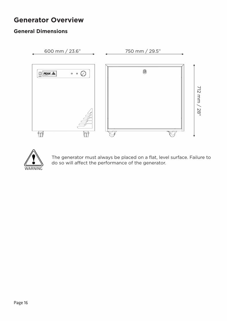
Generator Overview
General Dimensions
The generator must always be placed on a flat, level surface. Failure to do so will affect the performance of the generator.
WARNING
600 mm / 23.6” 750 mm / 29.5”
712 m
m / 28
"
Power Switch
Page 17
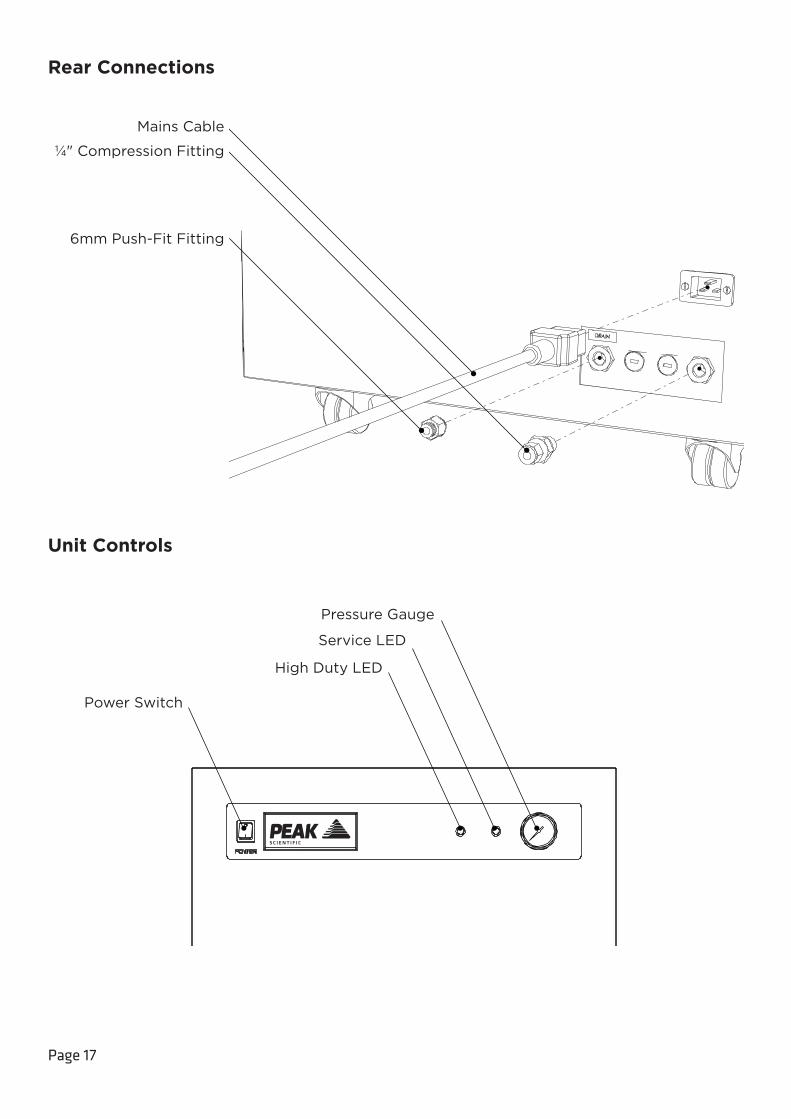
Rear Connections
Unit Controls
¼" Compression Fitting
6mm Push-Fit Fitting
Mains Cable
Service LED
Power Switch
Pressure Gauge
High Duty LED

Page 18
Drain ConnectionFit the 6mm push fit fitting to the drain port located on the output panel. Tighten using a 16mm or 5/8” spanner. Use the 6mm tubing to connect this to a suitable drain connection or container. It should be noted that the Generator can expel a considerable amount of water from this (dependant on ambient humidity).
If a container is used it should be emptied at regular intervals. The container must NOT have an air tight seal as water and air are expelled at pressure.
CAUTION

Page 19
WARNING
Electrical ConnectionConnect the generator to an appropriate 110 or 230 volt single-phase supply, refer to the generator serial plate for input specification and ensure your supply matches the requirements.
If the appropriate power cord is not supplied; a new plug, rated to at least 12 amps, can be fitted by a qualified electrician.
This unit is classified as SAFETY CLASS 1. THIS UNIT MUST BE EARTHED. Before connecting the unit to the mains supply, please check the information on the serial plate. The mains supply must be of the stated AC voltage and frequency.
EARTH/GROUND (E):- Green & Yellow or Green
LIVE (L):- Brown or Black
Neutral (N):- Blue or White
Electrical requirements are 110 or 230VAC nominal +/- 10% depending on chosen model. However, running continuously at voltages outwith this is not recommended. Extended periods at extremes can have a detrimental effect on the operation and life of the generator.
If the equipment is used in a manner not specified by the manufacturer, the protection provided by the equipment maybe impaired.
To ensure that the correct voltage is being supplied to the generator, the generator comes equipped with an inbuilt voltmeter. This is located on the underside of the compressor compartment, and will measure and display the mains voltage that is being supplied to the generator.
The voltmeter should be checked prior to the initial purge of the system.
If the reading is 219V or less, then we would highly recommend fitting a Dual Tap Transformer 06-3200. This can be ordered directly from Peak Scientific.
WARNING
Page 20
Start-Up SequenceBefore the Generator is connected to the application, the Generator should be operated in isolation (i.e. not connected to the application) for thirty minutes. This is to ensure any impurities present are purged from the system. Failure to do this may harm the application.
Before re-connecting the Generator to the mains and switching it on for the isolation run, it is necessary to fit the silencer to the outlet port of the output panel.
Once this is done, the Generator can be re-connected to the mains and switched on.
Pressure will start to build in the internal storage tanks which can be monitored by watching the output pressure gauge on the front panel. This will climb to the factory set pressure as noted in the specifications.
Once this pressure is reached, the compressors will continue to run until the internal tank upper pressure limit is reached and the compressor has run for a period of at least two and a half minutes.
The compressors will then rest until the internal tank lower pressure limits is reached. Once this limit is reached the compressors will switch back on again. This compressor cycling is normal and will continue throughout the operation of the Generator.
When the system has been operated for a period of 30 minutes, all the internal pipe-work and storage tanks will have been purged with Nitrogen.
The Generator is now purged and the tubes can be connected at the rear of the unit.
CAUTION
Page 21
Connecting to the applicationOnce the initial purge run of 30 minutes has completed, and the generator has been running for 1 hour, it is ready to be connected to the application(s).
The pressure in the internal storage tanks must be allowed to dissipate before connecting the generator to the application(s)
Attach the ¼” compression fitting to the outlet of the generator. Using the ¼” tubing supplied, connect the outlet of the generator to the inlet on the application.
If you require more tubing than is supplied please refer to the Tubing Lengths section.
Once the tubing is connected to the application, please ensure that it is thoroughly checked for being leak-tight. Even the slightest leak in the gas supply between the generator and the application can lead to a reduction in efficiency.
Tubing Lengths
The diameter of the tubing which will be connected to the gas outlet is important and is determined by the length of tubing required. Failure to follow these recommendations could lead to pressure between generator and application.
< 10 meters: Use ¼”/3⁄16” (¼” O/D, 3⁄16” I/D) P.T.F.E. tubing.
> 10 - 40 meters: Use 3⁄8”/ 5⁄16” (3⁄8” O/D, 5⁄16” I/D). Tubing and fittings not supplied
in the fittings kit.
> 40 metres: Please contact Peak Scientific with the relevant distance and we will calculate the flow resistance and the tubing size required.
A combination of ¼”/3⁄16” and 3⁄8”/5⁄16” tubing may be used to ensure that there is no large
diameter tubing within the lab (i.e. for the first 20 meters from the generator use 3⁄8”/5⁄16”
and the final 10 meters to the application use ¼”/3⁄16” tubing). Keep the connections and bends to a minimum.
CAUTION
CAUTION
CAUTION
Page 22
Normal OperationThe generator is designed specifically to minimize operator involvement. Given that the system is installed as described in earlier sections and is serviced in accordance with the specified maintenance recommendations (see Service Requirements), then it should simply be a matter of turning the generator on when it is required.
The generator will automatically produce the factory set flow and pressure as detailed in the Technical Specifications.
Normal Operation - Genius 1023The Genius 1023 Gas Generator is designed specifically to minimize operator involvement. It has two modes of operation which should be manually selected by the user to suit the intended application. The two options are:
1. Nitrogen - Should be used to obtain maximum purity Nitrogen.
2. Chip Cube - Should be selected to produce Nitrogen gas with a 10% oxygen content; as required by the chip cube application.
The Genius 1023 generator has an internal storage reservoir which ensures a quick start up as demand resumes. However, at a time when the user switches modes of operation, i.e. Nitrogen to Chip Cube, the generator will first purge the reservoir of unwanted gas before building pressure at the selected purity. This operation may take up to 5 minutes to complete. Machine readiness will be evident when the generator output gauge returns to normal operating pressure. (100psi)
Given that the system is installed as described in earlier sections and is serviced in accordance with the specified maintenance recommendations, then it should simply be a matter of turning the Generator on when it is required, and selecting the desired operating mode.
On Demand GasThe generator produces gas on demand. If the application is operating and requires a gas flow, the generator will supply this to suit the requirements of the application. If the application requirement for gas stops, the generator will also stop, once it has reached its upper set limit in the internal storage tanks. If the demand from the application starts again, the Generator will detect the demand for gas and will automatically start again to suit the demand.
Page 23
Generator CyclingThe generator is designed for the internal compressors to cycle. This cycling reduces the duty (run time) on the compressors. The rate at which they cycle will be dependent on the gas required to satisfy the demand of the application. If the application demands the maximum gas flow of the generator, the compressor duty will be higher, (the rest period in the compressor cycle will be shorter). If the application demand is lower than the maximum gas flow, then the duty on the compressors will decrease, (the rest period in the compressor cycle will be longer). If the generator is installed in an extreme en-vironment or is subjected to low supply voltage or high altitude the compressors may undergo periods where they do not cycle (see High Duty Indication).
Unusual OperationIf at any time the generator begins to emit excessive noise or vibration, then it should be switched off and you should contact Peak Scientific or the Peak Partner from which the generator has been purchased.
Page 24
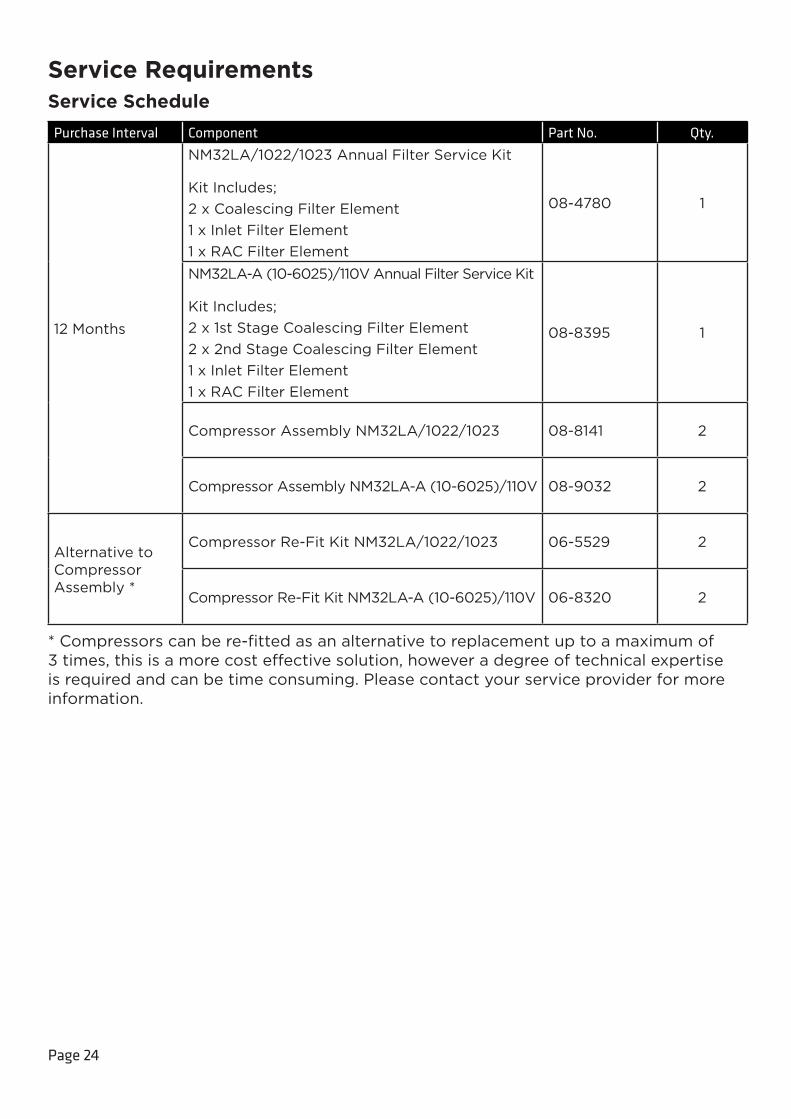
Service RequirementsService Schedule
Purchase Interval Component Part No. Qty.
12 Months
NM32LA/1022/1023 Annual Filter Service Kit
Kit Includes;2 x Coalescing Filter Element1 x Inlet Filter Element1 x RAC Filter Element
08-4780 1
NM32LA-A (10-6025)/110V Annual Filter Service Kit
Kit Includes;2 x 1st Stage Coalescing Filter Element2 x 2nd Stage Coalescing Filter Element1 x Inlet Filter Element1 x RAC Filter Element
08-8395 1
Compressor Assembly NM32LA/1022/1023 08-8141 2
Compressor Assembly NM32LA-A (10-6025)/110V 08-9032 2
Alternative to Compressor Assembly *
Compressor Re-Fit Kit NM32LA/1022/1023 06-5529 2
Compressor Re-Fit Kit NM32LA-A (10-6025)/110V 06-8320 2
* Compressors can be re-fitted as an alternative to replacement up to a maximum of 3 times, this is a more cost effective solution, however a degree of technical expertise is required and can be time consuming. Please contact your service provider for more information.
Page 25
Service IndicationThe generator will notify the user of the service interval for the internal compressors. The generator has the following Service Indication Stages:-
Stage 1Once either compressor requires a service the LED indicator (yellow) on the front of the generator will illuminate.
This is to make the user aware that a service of the generator is due and should be planned at the earliest convenience. The generator will continue to operate as normal with the LED on.
Stage 2If the service is not completed the generator will continue to run. After 2 weeks, the service LED indicator (yellow) will start to flash.
This is to make the user aware that the service of the generator is now overdue and must be completed immediately to ensure the continuous trouble free operation of the generator.
Service Indication ResetOnce the service has been completed the Service Indication LED can be reset in the main control PLC. This will be performed by the Peak Service Engineer or trained service representative that completes the service operation.
Page 26
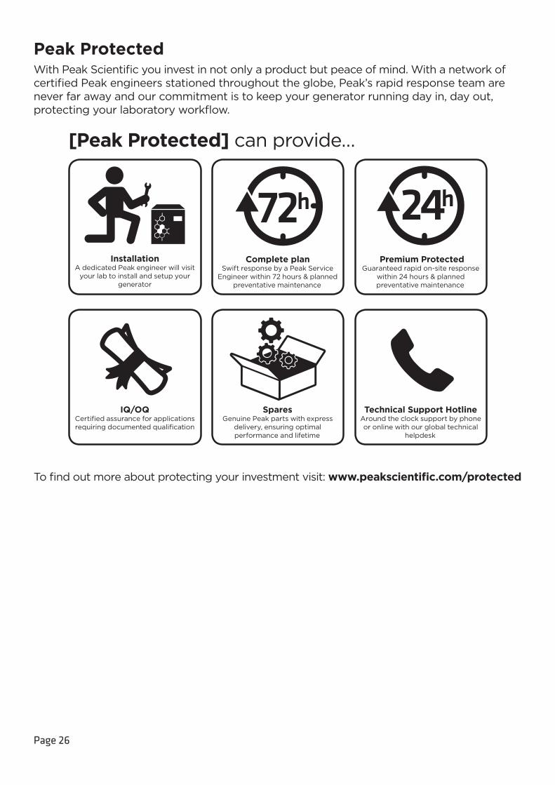
Peak ProtectedWith Peak Scientific you invest in not only a product but peace of mind. With a network of certified Peak engineers stationed throughout the globe, Peak’s rapid response team are never far away and our commitment is to keep your generator running day in, day out, protecting your laboratory workflow.
[Peak Protected] can provide…
Installation A dedicated Peak engineer will visit
your lab to install and setup your generator
IQ/OQCertified assurance for applications requiring documented qualification
Complete planSwift response by a Peak Service
Engineer within 72 hours & planned preventative maintenance
SparesGenuine Peak parts with express
delivery, ensuring optimal performance and lifetime
Premium ProtectedGuaranteed rapid on-site response
within 24 hours & planned preventative maintenance
Technical Support HotlineAround the clock support by phone or online with our global technical
helpdesk
To find out more about protecting your investment visit: www.peakscientific.com/protected
Page 27
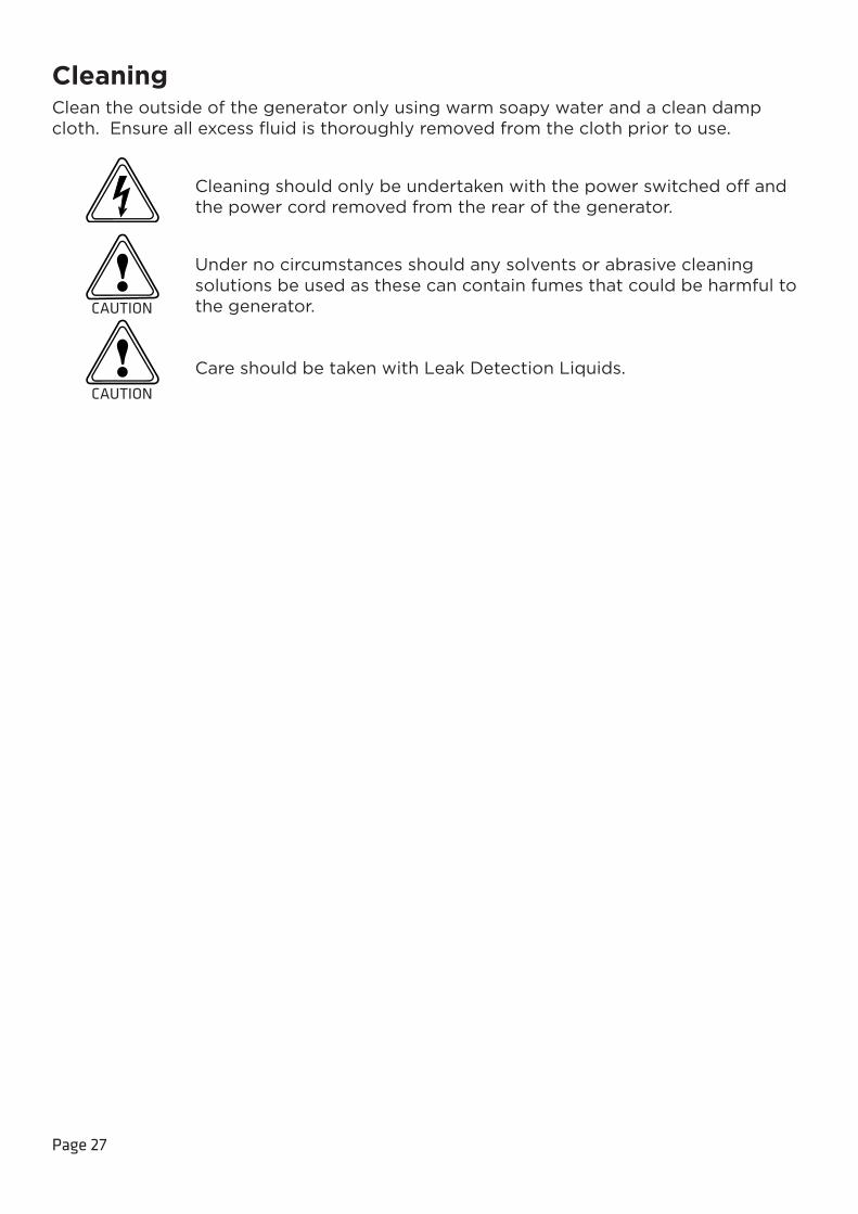
CleaningClean the outside of the generator only using warm soapy water and a clean damp cloth. Ensure all excess fluid is thoroughly removed from the cloth prior to use.
Cleaning should only be undertaken with the power switched off and the power cord removed from the rear of the generator.
Under no circumstances should any solvents or abrasive cleaning solutions be used as these can contain fumes that could be harmful to the generator.
Care should be taken with Leak Detection Liquids.
CAUTION
CAUTION
Page 28
High Duty IndicationThe generator has a ‘HIGH DUTY’ indicator on the front panel. This indicator monitors the running condition of the internal compressors and illuminates when they have been operating continually for a period of 8 hours.
There are a number of extreme conditions that can affect the duty cycling of the compressors inside the generator. These extremes include very high ambient temperatures, low supply voltages, a very high flow requirement and locations of high altitude. Any one of these or a combination of a number of these extremes can be evident in a customer site.
While the generator is designed to operate fully in these conditions it should be noted that the effect of these extremes can force the compressors to run continually. The compressors are fully capable of running continually with no detrimental effect.
High Duty Indication ResetIf the compressors have been operating continually for a period of 8 hours the indicator light will be illuminated. Once the compressors return to a cycling mode the indicator light will automatically switch off. There is no manual intervention required.
Indication of FaultIn most installations the ‘HIGH DUTY’ indicator will never be illuminated. If your generator has been operating for a significant period of time, then suddenly develops a ‘HIGH DUTY’ indication with no apparent change in environmental conditions or flow requirements, it may be indicative of a problem with the system such as an external leak or imminent compressor failure.
If this is the case you should contact Peak Scientific or your service provider.
It should be noted that the generator will continue to operate so long as it can maintain pressure during this indication.

Page 29
Troubleshooting
Problem Possible Solution
The generator will not switch on and the power switch does not illuminate.
• Ensure power cord is plugged into the generator and that the power socket is turned on.
• Check the fuse in the power cord plug.
• Contact your service provider.
Compressors are running but pressure is not building. • Contact your service provider.
The mass spec is reporting low pressure.• Check pressure gauges are showing
normal pressure.
• Contact your service provider.
Yellow “SERVICE” LED on front panel is on constantly.
• A compressor(s) due for service. Contact your service provider.
• Refer to Service Indication section of this manual for further information.
Yellow “SERVICE” LED on front panel is flashing.
• A compressor(s) is overdue for service. Contact your service provider urgently.
• Refer to Service Indication section of this manual for further information.
Yellow “HIGH DUTY” LED on front panel is on constantly.
• A compressor(s) has not cycled for a period of 8 hours. Refer to the High Duty Indication section of this manual.
• Ensure ambient temperatures are within the specification.
• Ensure there are no leaks between the Generator and the mass spec.

Page 30
Go Online or Complete and ReturnYou can register for your FREE 12 month Warranty with ease online at www.peakscientific/protected.
Alternatively, you can send the completed form to Peak Scientific by post or email at [email protected].
Product Warranty Registration
Contact name
Email address
Company
Address
City/town
Postcode
Country
Telephone
Generator serial #
Model type
Installation date
Do you still use an alternative gas solution i.e. cylinders or bulk liquid?
Yes No
What gas requirements do you have in your lab? Hydrogen Nitrogen Zero Air
Extend your cover withPeak Scientific offer comprehensive gas generator after sales support packages. Peak [Protected] aftercare support can guarantee an on-site response within 72 hours*, genuine parts from our ISO9001 approved factory and a 95% first-time fix rate. See our enclosed Peak [Protected] leaflet for further information.
Important!
You have 1 month to register your Peak Scientific product from the date of installation. Once registered the warranty will be honoured for a period of 12 months. If you wish to defer the installation of your generator, you must notify Peak Scientific immediately by emailing [email protected]. For generators that remain unregistered after 1 month from the shipment date, the warranty will be considered active from the date of factory dispatch.
* Complete Plan only
Go Online or Complete and ReturnWe know that registering any of your recently purchased products is not the first thing on your mind- but it is very important to both of us. Not all warranties are alike and Peak Scientific stand out against other gas suppliers as we offer a comprehensive, quick response, on-site warranty. This means that in the very unlikely case that your gas generator develops a fault we have rapid support teams on-hand around the world who are able to come to your lab and get you back up and running in no time.
Register for your comprehensive 12 month on-site warranty with ease online at www.peakscientific.com/protected.
Alternatively, you can send the completed form to Peak Scientific by post or email at [email protected].
Important!
You have 1 month to register your Peak Scientific product from the date of installation. Once registered the warranty will be honoured for a period of 12 months. If you wish to defer the installation of your generator, you must notify Peak Scientific immediately by emailing [email protected]. For generators that remain unregistered after 1 month from the shipment date, the warranty will be considered active from the date of factory dispatch.

For further information on any of our generator products please contact [email protected]
Peak Scientific has highly trained, fully certified Field Service Engineers located in over 20 countries
across every continent around the world. This allows us to provide an industry-leading rapid response
service to our customers. With [Peak Protected], your laboratory’s productivity becomes our top
priority.
To discuss Peak Protected generator cover and payment options speak to your local Peak
Representative or for further information contact: [email protected]
Genius1022-1023-NM32LA User Manual Rev 2 PN UM-0001 29/07/16
Peak Scientific
Fountain Crescent
Inchinnan Business Park
Inchinnan
PA4 9RE
Scotland, UK
Tel: +44 141 812 8100
Fax: +44 141 812 8200