geo diagnostic terminal (gdt) (for use with … · vital user i/o, vital & non-vital user...
TRANSCRIPT

PRINTED IN U.S.A.
USER'S HANDBOOK GEO DIAGNOSTIC TERMINAL (GDT) (FOR USE WITH LAPTOP OR DESK-TOP PC) APRIL 2002 (REVISED AUGUST 2015)
DOCUMENT NO. SIG-00-01-14 VERSION C.1
Siemens Industry, Inc. Rail Automation 9568 Archibald Ave., Suite 100, Rancho Cucamonga, California 91730
1-800-793-SAFE Copyright © 2002 - 2015 Siemens Industry, Inc. All rights reserved

ii SIG-00-01-14 APRIL 2002 (REVISED AUGUST 2015) Version No.: C.1
PROPRIETARY INFORMATION Siemens Industry, Inc. has a proprietary interest in the information contained herein and, in some instances, has patent rights in the systems and components described. It is requested that you distribute this information only to those responsible people within your organization who have an official interest. This document or the information disclosed herein, shall not be reproduced or transferred to other documents or used or disclosed for manufacturing or for any other purpose except as specifically authorized in writing by Siemens Industry, Inc.
TRANSLATIONS
The manuals and product information of Siemens Industry, Inc. are intended to be produced and read in English. Any translation of the manuals and product information are unofficial and can be imprecise and inaccurate in whole or in part. Siemens Industry, Inc. does not warrant the accuracy, reliability, or timeliness of any information contained in any translation of manual or product information from its original official released version in English and shall not be liable for any losses caused by such reliance on the accuracy, reliability, or timeliness of such information. Any person or entity that relies on translated information does so at his or her own risk.
WARRANTY INFORMATION
Siemens Industry, Inc. warranty policy is as stated in the current Terms and Conditions of Sale document. Warranty adjustments will not be allowed for products or components which have been subjected to abuse, alteration, improper handling or installation, or which have not been operated in accordance with Seller's instructions. Alteration or removal of any serial number or identification mark voids the warranty.
SALES AND SERVICE LOCATIONS
Technical assistance and sales information on Siemens Industry, Inc. products may be obtained at the following locations:
SIEMENS INDUSTRY, INC. RAIL AUTOMATION SIEMENS INDUSTRY, INC.RAIL AUTOMATION 2400 NELSON MILLER PARKWAY 939 S. MAIN STREET LOUISVILLE, KENTUCKY 40223 MARION, KENTUCKY 42064 TELEPHONE: (502) 618-8800 TELEPHONE: (270) 918-7800 FAX: (502) 618-8810 CUSTOMER SERVICE: (800) 626-2710 SALES & SERVICE: (800) 626-2710 TECHNICAL SUPPORT: (800) 793-7233 WEB SITE: www.siemens.com/rail-automation FAX: (270) 918-7830
iii SIG-00-01-14 APRIL 2002 (REVISED AUGUST 2015) Version No.: C.1
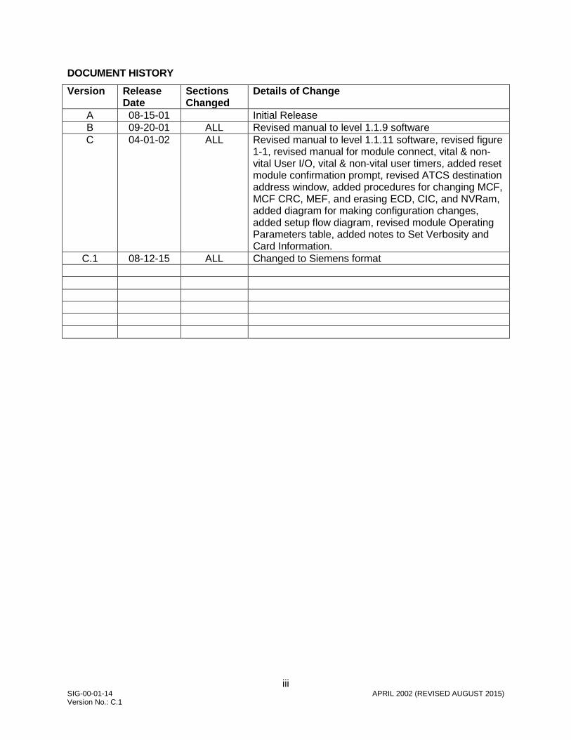
DOCUMENT HISTORY
Version Release Date
Sections Changed
Details of Change
A 08-15-01 Initial Release B 09-20-01 ALL Revised manual to level 1.1.9 software C 04-01-02 ALL Revised manual to level 1.1.11 software, revised figure
1-1, revised manual for module connect, vital & non-vital User I/O, vital & non-vital user timers, added reset module confirmation prompt, revised ATCS destination address window, added procedures for changing MCF, MCF CRC, MEF, and erasing ECD, CIC, and NVRam, added diagram for making configuration changes, added setup flow diagram, revised module Operating Parameters table, added notes to Set Verbosity and Card Information.
C.1 08-12-15 ALL Changed to Siemens format
iv SIG-00-01-14 APRIL 2002 (REVISED AUGUST 2015) Version No.: C.1
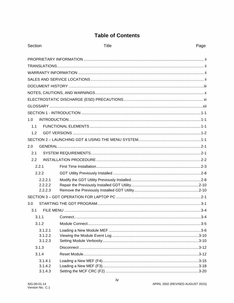
Table of Contents
Section Title Page
PROPRIETARY INFORMATION .................................................................................................................. ii
TRANSLATIONS ........................................................................................................................................... ii
WARRANTY INFORMATION ....................................................................................................................... ii
SALES AND SERVICE LOCATIONS ........................................................................................................... ii
DOCUMENT HISTORY ................................................................................................................................ iii
NOTES, CAUTIONS, AND WARNINGS ....................................................................................................... x
ELECTROSTATIC DISCHARGE (ESD) PRECAUTIONS ........................................................................... xi
GLOSSARY ................................................................................................................................................. xii
SECTION 1 - INTRODUCTION ................................................................................................................. 1-1
1.0 INTRODUCTION ............................................................................................................................. 1-1
1.1 FUNCTIONAL ELEMENTS ......................................................................................................... 1-1
1.2 GDT VERSIONS ......................................................................................................................... 1-2
SECTION 2 – LAUNCHING GDT & USING THE MENU SYSTEM ........................................................... 1-1
2.0 GENERAL ....................................................................................................................................... 2-1
2.1 SYSTEM REQUIREMENTS ........................................................................................................ 2-1
2.2 INSTALLATION PROCEDURE ................................................................................................... 2-2
2.2.1 First Time Installation ................................................................................................... 2-3
2.2.2 GDT Utility Previously Installed ................................................................................... 2-8
2.2.2.1 Modify the GDT Utility Previously Installed .................................................................. 2-8 2.2.2.2 Repair the Previously Installed GDT Utility ................................................................ 2-10 2.2.2.3 Remove the Previously Installed GDT Utility ............................................................. 2-10
SECTION 3 – GDT OPERATION FOR LAPTOP PC ................................................................................ 2-1
3.0 STARTING THE GDT PROGRAM.................................................................................................. 3-1
3.1 FILE MENU ................................................................................................................................. 3-4
3.1.1 Connect........................................................................................................................ 3-4
3.1.2 Module Connect ........................................................................................................... 3-5
3.1.2.1 Loading a New Module MEF ....................................................................................... 3-6 3.1.2.2 Viewing the Module Event Log .................................................................................. 3-10 3.1.2.3 Setting Module Verbosity ........................................................................................... 3-10
3.1.3 Disconnect ................................................................................................................. 3-12
3.1.4 Reset Module ............................................................................................................. 3-12
3.1.4.1 Loading a New MEF (F4)........................................................................................... 3-15 3.1.4.2 Loading a New MEF (F3)........................................................................................... 3-18 3.1.4.3 Setting the MCF CRC (F2) ........................................................................................ 3-20

v SIG-00-01-14 APRIL 2002 (REVISED AUGUST 2015) Version No.: C.1
3.1.4.4 Erasing the ECD (F5) ................................................................................................ 3-22 3.1.4.5 Erasing the CIC (F6) .................................................................................................. 3-24 3.1.4.6 Erasing the NVRAM (F7) ........................................................................................... 3-26 3.1.4.7 Exitng the Setup Program (F8) .................................................................................. 3-28
3.1.5 Exit ............................................................................................................................. 3-28
3.2 CONFIGURE MENU ................................................................................................................. 3-28
3.2.1 Vital User Options ...................................................................................................... 3-28
3.2.2 Non-Vital User Options .............................................................................................. 3-35
3.2.3 Vital User I/O ............................................................................................................. 3-38
3.2.4 Non-Vital User I/O ...................................................................................................... 3-44
3.2.5 Vital User Timers ....................................................................................................... 3-46
3.2.6 Non-Vital User Timers ............................................................................................... 3-54
3.2.7 Set SIN....................................................................................................................... 3-56
3.2.8 Set UCN ..................................................................................................................... 3-62
3.2.8.1 UCN for Installers Version Only ................................................................................. 3-64 3.2.8.2 UCN for Maintainers Version Only ............................................................................ 3-67
3.2.9 Set Time..................................................................................................................... 3-69
3.2.10 Delete MCF ................................................................................................................ 3-70
3.3 SETUP MENU ........................................................................................................................... 3-71
3.3.1 Communication .......................................................................................................... 3-72
3.3.2 Destination Address ................................................................................................... 3-73
3.4 TOOLS MENU ........................................................................................................................... 3-76
3.5 VIEW MENU .............................................................................................................................. 3-77
3.5.1 CPU Version .............................................................................................................. 3-77
3.5.2 Logic States ............................................................................................................... 3-78
3.5.3 DT Staistics ................................................................................................................ 3-80
3.5.4 Refresh ...................................................................................................................... 3-81
3.6 HELP MENU .............................................................................................................................. 3-81
3.7 INDIVIDUAL MODULE SETUP ................................................................................................. 3-82
3.7.1 Module Menu ............................................................................................................. 3-84
3.7.1.1 Configuration Parameters .......................................................................................... 3-85 3.7.1.2 Operating Parameters ............................................................................................... 3-85 3.7.1.3 Event History ............................................................................................................. 3-94 3.7.1.4 Reset........................................................................................................................ 3-100 3.7.1.5 Set Verbosity ........................................................................................................... 3-101 3.7.1.6 Card Information ...................................................................................................... 3-102
SECTION 4 – GDT PROTOCOLS ............................................................................................................. 3-1
4.0 GDT PROTOCOL DESCRIPTIONS ............................................................................................... 4-1
4.1 SESSION PROTOCOL ............................................................................................................... 4-1

vi SIG-00-01-14 APRIL 2002 (REVISED AUGUST 2015) Version No.: C.1
4.2 VITAL CONFIGURATION PROTOCOL ...................................................................................... 4-1
4.3 UCN CONFIGURATION PROTOCOL ........................................................................................ 4-3

vii SIG-00-01-14 APRIL 2002 (REVISED AUGUST 2015) Version No.: C.1
List of Figures
Section Title Page Figure 1-1 GDT Functional Elements ...................................................................................................... 1-2 Figure 2-1 GEO™ Diagnostic Terminal Installation Wizard Window ....................................................... 2-2 Figure 2-2 GEO™ License Agreement Window ...................................................................................... 2-3 Figure 2-3 Installation Destination Window .............................................................................................. 2-4 Figure 2-4 Program Folder Selection Window ......................................................................................... 2-4 Figure 2-5 Installation Summary Window ................................................................................................ 2-5 Figure 2-6 Microsoft® XML Parser Setup Window ................................................................................... 2-6 Figure 2-7 GDT Installation Window ........................................................................................................ 2-6 Figure 2-8 GDT Release Notes Window .................................................................................................. 2-7 Figure 2-9 GDT Restart Window .............................................................................................................. 2-7 Figure 2-10 “Modify, Repair, or Remove the Program” Window.............................................................. 2-8 Figure 2-11 Select Components Window ................................................................................................ 2-9 Figure 2-12 Maintenance Complete Window ........................................................................................... 2-9 Figure 2-13 Confirm File Deletion Window ............................................................................................ 2-10 Figure 3-1 GDT Initialiaztion Display ....................................................................................................... 3-1 Figure 3-2 GDT Data Download Display .................................................................................................. 3-1 Figure 3-3 Example of GDT Module Assignement Display ..................................................................... 3-2 Figure 3-4 Active File Menu Options When Communication has been Established ............................... 3-4 Figure 3-5 Module Connect Display ....................................................................................................... 3-5 Figure 3-6 Reset Module Confirmation Prompt ....................................................................................... 3-6 Figure 3-7 Typical Module Boot Screen ................................................................................................... 3-7 Figure 3-8 Selecting the “Change MEF” (F4) Function Key .................................................................... 3-7 Figure 3-9 Responding to the “Erase the MEF (Y/N)? Prompt ................................................................ 3-8 Figure 3-10 Selecting the MEF to Load ................................................................................................... 3-8 Figure 3-11 Erasing, Downloading, and Burning the MEF ...................................................................... 3-9 Figure 3-12 Setup Finished Screen ......................................................................................................... 3-9 Figure 3-13 Typical Online Module Event History Display ..................................................................... 3-10 Figure 3-14 Verbosity Warning Screen .................................................................................................. 3-11 Figure 3-15 Module Verbosity Screen ................................................................................................... 3-11 Figure 3-16 DT Screen when Communication is Broken ....................................................................... 3-12 Figure 3-17 DT Screen when Communication Cannot be Re-established ............................................ 3-12 Figure 3-18 Reset Module Confirmation Prompt ................................................................................... 3-13 Figure 3-19 Initial Bootstrap Text Terminal Screen ............................................................................... 3-13 Figure 3-20 Typical CPU Boot Screen ................................................................................................... 3-14 Figure 3-21 Change Setup Screen ........................................................................................................ 3-15 Figure 3-22 Selecting the “Change MEF” (F4) Function Key ................................................................ 3-16 Figure 3-23 Responding to the “Erase the MEF (Y/N)?” Prompt ........................................................... 3-16 Figure 3-24 Selecting the MEF to Load ................................................................................................. 3-17 Figure 3-25 Erasing, Downloading, and Burning the MEF .................................................................... 3-17 Figure 3-26 Select the “Change MCF” (F3) Function Key ..................................................................... 3-18 Figure 3-27 Browsing for the MCF to Load ............................................................................................ 3-19 Figure 3-28 Scrolling up to View the Previous MCF CRC ..................................................................... 3-20 Figure 3-29 MCFCRC Window .............................................................................................................. 3-21 Figure 3-30 Setup Finished Window ...................................................................................................... 3-21 Figure 3-31 Selecting the “Erase ECD” (F5) Function Key .................................................................... 3-22 Figure 3-32 Responding to the “Erase the ECD (Y/N)?” Prompt ........................................................... 3-23 Figure 3-33 ECD Cleared....................................................................................................................... 3-23 Figure 3-34 Selecting “Erase CIC” (F6) Function Key ........................................................................... 3-24 Figure 3-35 Responding to the “Erase the CIC (Y/N)?” Prompt ............................................................ 3-25 Figure 3-36 CIC Cleared ........................................................................................................................ 3-25 Figure 3-37 Selecting the “Erase NVRAM” (F7) Function Key .............................................................. 3-26

viii SIG-00-01-14 APRIL 2002 (REVISED AUGUST 2015) Version No.: C.1
Figure 3-38 Responding to the “Erase the NVRAM (Y/N)” Prompt ....................................................... 3-27 Figure 3-39 Clearing the NVRAM .......................................................................................................... 3-27 Figure 3-40 Setup Finshed Screen ........................................................................................................ 3-28 Figure 3-41 Typical Vital User Options Configuration Display with Current Values .............................. 3-30 Figure 3-42 Typical Vital User Options Configuration Display after Initial Changes.............................. 3-32 Figure 3-43 Typical Vital User Options Config Display with Confirmation CRC Entered ...................... 3-33 Figure 3-44 Typical Vital User Config Display with “Changes succeeded” Statement .......................... 3-33 Figure 3-45 Typical Vital User Options Config Display with “No Changes Pending” Statement ........... 3-35 Figure 3-46 Typical Non-Vital User Options Config Display with Current Values ................................. 3-37 Figure 3-47 Typical Vital User I/O Configuration with Current Values ................................................... 3-39 Figure 3-48 Typical Vital User I/O Configuration Display after Initial Changes ..................................... 3-41 Figure 3-49 Typical Vital User I/O Configuration Display with Confirmation CRC Entered ................... 3-42 Figure 3-50 Prompt to Press Any Push Button ...................................................................................... 3-43 Figure 3-51 Typical Vital User I/O Config Display with “Changes succeeded” Statement .................... 3-43 Figure 3-52 Typical Non-Vital User I/O Config Display with Current values .......................................... 3-45 Figure 3-53 Typical Non-Vital User I/O Config Display After Change ................................................... 3-46 Figure 3-54 Typical Vital User Timers Configuration Display with Current Values................................ 3-48 Figure 3-55 Typical Vital user Timers Configuration Display ................................................................. 3-50 Figure 3-56 Typical Vital User Tomer Config Display with Confirmation CRC Entered ........................ 3-51 Figure 3-57 Typical Vital User Timers Config Display with “Changes succeeded” Statement .............. 3-52 Figure 3-58 Typical Vital User Timers Config Display Showing Pending Timers and Values ............... 3-53 Figure 3-59 Typical Non-Vital User Timers Config Display with Current Values ................................... 3-55 Figure 3-60 Typical Non-Vital User Timers Config Display after Changes ............................................ 3-56 Figure 3-61 Typical Set SIN Display with Current SIN .......................................................................... 3-57 Figure 3-62 Typical Set SIN Display with New SIN ............................................................................... 3-59 Figure 3-63 Typical Set SIN Display with Confirmation CRC Entered .................................................. 3-60 Figure 3-64 Typical Set SIN Display with “Changes succeeded” Statement ......................................... 3-60 Figure 3-65 Set UCN Display (Installers Version).................................................................................. 3-63 Figure 3-66 Set UCN Display (Installers Version) with Generated UCN ............................................... 3-64 Figure 3-67 Set UCN Display (Installers Version) “Changes saved successfully” ................................ 3-65 Figure 3-68 Set UCN Display (Installers Version) “Error UCN Incorrect” .............................................. 3-66 Figure 3-69 Set UCN Display (Maintainers Version) “Changes saved successfully” ............................ 3-67 Figure 3-70 Set UCN Display (Maintainers Version) “Error: UCN incorrect” ......................................... 3-68 Figure 3-71 Time Window ...................................................................................................................... 3-70 Figure 3-72 Serial Port Settings Display ................................................................................................ 3-72 Figure 3-73 Windows® Task List with Multiple GDT Diagnostic Terminal Occurrences ........................ 3-73 Figure 3-74 Destination Address Menu ................................................................................................. 3-73 Figure 3-75 GDT Data Download Display (Following Local Destination Address Selection) ................ 3-74 Figure 3-76 Remote Destination Address Display ................................................................................. 3-74 Figure 3-77 Typical Sniffer Display ........................................................................................................ 3-76 Figure 3-78 Typical GDT CPU Version Display ..................................................................................... 3-77 Figure 3-79 Typical GDT Logic States Entry Display ............................................................................ 3-79 Figure 3-80 Typical GDT Logic States Listing Display .......................................................................... 3-79 Figure 3-81 Typical GDT Statistics Display ........................................................................................... 3-80 Figure 3-82 GDT Statistics Type Display ............................................................................................... 3-81 Figure 3-83 About GEO™ Diagnostic Terminal ..................................................................................... 3-81 Figure 3-84 Making Configuration Changes .......................................................................................... 3-82 Figure 3-85 Setup Flow Diagram ........................................................................................................... 3-83 Figure 3-86 Example of Module Assignment Display ............................................................................ 3-84 Figure 3-87 Module Pop-up Menu ......................................................................................................... 3-85 Figure 3-88 Typical Module Configuration Parameters Display ............................................................ 3-85 Figure 3-89 Textual Operating Parameter Option Selection .................................................................. 3-91 Figure 3-90 Typical Textual Values Drop-Down List ............................................................................. 3-92 Figure 3-91 Numerical Operating Parameter Option Selection ............................................................. 3-92 Figure 3-92 Typical Operating Parameter Value “Out of Range” Error Message .................................. 3-94 Figure 3-93 Typical Online Event History Display.................................................................................. 3-94
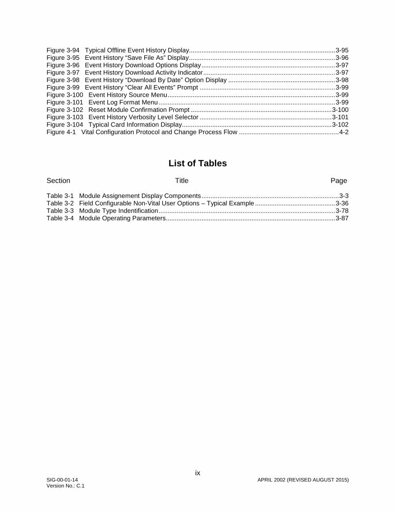
ix SIG-00-01-14 APRIL 2002 (REVISED AUGUST 2015) Version No.: C.1
Figure 3-94 Typical Offline Event History Display.................................................................................. 3-95 Figure 3-95 Event History “Save File As” Display .................................................................................. 3-96 Figure 3-96 Event History Download Options Display ........................................................................... 3-97 Figure 3-97 Event History Download Activity Indicator .......................................................................... 3-97 Figure 3-98 Event History “Download By Date” Option Display ............................................................ 3-98 Figure 3-99 Event History “Clear All Events” Prompt ............................................................................ 3-99 Figure 3-100 Event History Source Menu .............................................................................................. 3-99 Figure 3-101 Event Log Format Menu ................................................................................................... 3-99 Figure 3-102 Reset Module Confirmation Prompt ............................................................................... 3-100 Figure 3-103 Event History Verbosity Level Selector .......................................................................... 3-101 Figure 3-104 Typical Card Information Display.................................................................................... 3-102 Figure 4-1 Vital Configuration Protocol and Change Process Flow ........................................................ 4-2
List of Tables
Section Title Page Table 3-1 Module Assignement Display Components ............................................................................. 3-3 Table 3-2 Field Configurable Non-Vital User Options – Typical Example ............................................. 3-36 Table 3-3 Module Type Indentification ................................................................................................... 3-78 Table 3-4 Module Operating Parameters ............................................................................................... 3-87

x SIG-00-01-14 APRIL 2002 (REVISED AUGUST 2015) Version No.: C.1
NOTES, CAUTIONS, AND WARNINGS Throughout this manual, notes, cautions, and warnings are frequently used to direct the reader’s attention to specific information. Use of the three terms is defined as follows:
WARNING
INDICATES A POTENTIALLY HAZARDOUS SITUATION WHICH, IF NOT AVOIDED, COULD RESULT IN DEATH OR SERIOUS INJURY. WARNINGS ALWAYS TAKE PRECEDENCE OVER NOTES, CAUTIONS, AND ALL OTHER INFORMATION.
CAUTION
REFERS TO PROPER PROCEDURES OR PRACTICES WHICH IF NOT STRICTLY OBSERVED, COULD RESULT IN A POTENTIALLY HAZARDOUS SITUATION AND/OR POSSIBLE DAMAGE TO EQUIPMENT. CAUTIONS TAKE PRECEDENCE OVER NOTES AND ALL OTHER INFORMATION, EXCEPT WARNINGS.
NOTE
Generally used to highlight certain information relating to the topic under discussion.
If there are any questions, contact Siemens Industry, Inc. Application Engineering.

xi SIG-00-01-14 APRIL 2002 (REVISED AUGUST 2015) Version No.: C.1
ELECTROSTATIC DISCHARGE (ESD) PRECAUTIONS
Static electricity can damage electronic circuitry, particularly low voltage components such as the integrated circuits commonly used throughout the electronics industry. Therefore, procedures have been adopted industry-wide which make it possible to avoid the sometimes invisible damage caused by electrostatic discharge (ESD) during the handling, shipping, and storage of electronic modules and components. Siemens Industry, Inc. has instituted these practices at its manufacturing facility and encourages its customers to adopt them as well to lessen the likelihood of equipment damage in the field due to ESD. Some of the basic protective practices include the following:
• Ground yourself before touching card cages, assemblies, modules, or components.
• Remove power from card cages and assemblies before removing or installing modules.
• Remove circuit boards (modules) from card cages by the ejector lever only. If an ejector lever is not provided, grasp the edge of the circuit board but avoid touching circuit traces or components.
• Handle circuit boards by the edges only.
• Never physically touch circuit board or connector contact fingers or allow these fingers to come in contact with an insulator (e.g., plastic, rubber, etc.).
• When not in use, place circuit boards in approved static-shielding bags, contact fingers first. Remove circuit boards from static-shielding bags by grasping the ejector lever or the edge of the board only. Each bag should include a caution label on the outside indicating static-sensitive contents.
• Cover workbench surfaces used for repair of electronic equipment with static dissipative workbench matting.
• Use integrated circuit extractor/inserter tools designed to remove and install electrostatic-sensitive integrated circuit devices such as PROM’s (OK Industries, Inc., Model EX-2 Extractor and Model MOS-40 Inserter (or equivalent) are highly recommended).
• Utilize only anti-static cushioning material in equipment shipping and storage containers.
For information concerning ESD material applications, please contact the Technical Support Staff at 1-800-793-7233. ESD Awareness Classes and additional ESD product information are also available through the Technical Support Staff.

xii SIG-00-01-14 APRIL 2002 (REVISED AUGUST 2015) Version No.: C.1
GLOSSARY
CIC: Chassis ID Chip – A serial memory devcice physically located on the GEO chassis and used to store the UCN, SIN, and site/module parameters.
CRC: Cyclic Redundancy Check – The CRC data is calculated and appended to a file so that it can be verified that no data is lost or corrupted.
DT: Diagnostic Terminal – A PC (usually a laptop or Pocket PC) that is used to configure the GEO system via the DT port(s) on the CPU/CPU2 module. The GDT utility software must be installed.
Echelon LAN: A local twisted pair network implemented using the Neuron network chip.
ECD: External Configuration Device – A removable memory device used for storing the module configuration data.
LAN: Local Area Network – A limited network where the data transfer media is generally wires or cable.
MCF: Module Configuration File – The site-specific configuration data which is downloaded into the HD/LINK Module or GEO unit.
MCF CRC: Module Configuration File Cyclic Redundancy Check – A configuration validation number calculated from the contents of an approved MCF and issued to be stored in the CIC for the purpose of verifying proper configuration.
MEF: Module Executable File – The HD/LINK or GEO unit executable software.
SIN: Site (Subnode) Identification Number – A twelve-digit ATCS address representing the module as a subnode on the network.
UCN: Unique Check Number – A configuration validation number calculated from the contents of an approved MCF and MEF and issued to be entered into an HD/LINK module or GEO unit for the purpose of verifying proper configuration.
VLO: Vital Lamp Output – A software-driven vital hardware output which drives a lamp on a Colorlight Signal or Search Light Signal to display a commanded aspect, and verifies the lamp is operational (not shorted or out).

xiii SIG-00-01-14 APRIL 2002 (REVISED AUGUST 2015) Version No.: C.1
GLOSSARY (CONCLUDED)
VPI: Vital Parallel Input – A module input the function of which affects the safety of train operation.
VRO: Vital Relay Output – A module output the function of which affects the safety of train operation.

xiv SIG-00-01-14 APRIL 2002 (REVISED AUGUST 2015) Version No.: C.1
This Page Intentionally Left Blank

INTRODUCTION _________________________________________________________________________________________________________
1-1 SIG-00-01-14 APRIL 2002 (REVISED AUGUST 2015) Version No.: C.1
SECTION 1 - INTRODUCTION 1.0 INTRODUCTION The GEO Diagnostic Terminal (GDT) utility is a software tool that may be used for analysis and maintenance of GEO units. The GDT utility may be installed on either a laptop (or desktop) PC, or a Pocket PC, and transported to a field site where the GDT can be used to perform the following functions: • Monitoring GEO equipment • Diagnostics for fault isolation and maintenance • Setting Vital and Non-vital User Options • Setting Vital and Non-vital User I/O • Setting Vital and Non-vital User Timers • Setting I/O card Configuration Parameters • Setting I/O card Operating Parameters • Downloading a new MEF (module executive file) • Downloading a new MCF (module configuration file) • Setting the MCF CRC (module configuration file cyclic redundancy check number) • Setting the UCN (configuration unique check number) • Setting the SIN (ATCS site identification number) The GDT is generally connected to the DT port on the CPU module or the CP DT port on the CPU2 module for equipment monitoring. It is capable of connecting directly to the DT ports on the I/O modules or VLP on the CPU2 module to download new MEFs or to obtain event logs.
NOTE
This handbook describes the GDT utility for use on the laptop PC (or desktop PC) platform only. For the GDT utility for use on the Pocket PC platform, refer to document number SIG-00-01-13.
1.1 FUNCTIONAL ELEMENTS
The GDT consists of three functional elements: • Configuration Controller • Dynamic Configuration Display • Text Screen The relationships between each of these elements, the field ATCS database, and a GEO™ field unit are shown in Figure 1-1.

INTRODUCTION _________________________________________________________________________________________________________
1-2 SIG-00-01-14 APRIL 2002 (REVISED AUGUST 2015) Version No.: C.1
Figure 1-1 GDT Functional Elements The Configuration Controller enables transfer of an MCF to the external configuration device (ECD) of the GEO™ field unit. The Configuration Controller also allows the module configuration file cyclic redundancy check (MCF CRC) number, the unique check number (UCN), and the site identification number (SIN) to be entered and transferred to the CIC (chassis identification chip) on the GEO™ unit. These numbers are obtained either from the unit MCF Installation Listing printout or from the unit MCF Approval Listing printout. The Configuration controller also enables MEF updates to be downloaded to flash memory within the field unit. The Dynamic Configuration Display presents a dynamic graphic display of the field unit configuration, while the Text Screen displays the field unit Event Log. Together, these displays may be used to analyze the operation of the field unit.
1.2 GDT VERSIONS
There are two different versions of the GDT: Installer version and Maintainer version. Only authorized railroad personnel are issued the Installer version. The Installer version allows the user to request that the GEO™ unit calculate the new UCN for the new parameters to be stored in the CIC. The Maintainer must be issued the new UCN.
WARNING
CARE SHOULD BE EXERCISED IN THE DISTRI-BUTION AND USE OF THE INSTALLER VERSION OF THE GDT. BECAUSE THE INSTALLER VERSION CAN CALCULATE THE UCN FOR ANY CHANGES IN VITAL OPTIONS, THE POTENTIAL EXISTS FOR IMPROPER OR UNSAFE VITAL OPTION INPUT TO THE SYSTEM.
Dynamic Configuration
Display
Screen Text
Terminal Utility (GDT) GEO™ Diagnostic
UCN SIN
MCF
MEF Configuration
Controller
Field Computer (Laptop or Desktop PC)
GEO™ Field Unit
I/O Card Configuration Parameters
SIN
MCF
Configuration Data
Event Data
MEF
UCN
User Options, I/O, Timers Directories Safetran
MCF
MEF
Field ATCS Database
Flash Memory
Event Log
ECD
COMM Port
DT Port
I/O Card Operating Parameters
CPU/CPU2 Module
CIC MCF CRC
Site Specific Data

LAUNCHING GDT & USING THE MENU SYSTEM (FOR LAPTOP/DESKTOP PC VERSION) _________________________________________________________________________________________________________
2-1 SIG-00-01-14 APRIL 2002 (REVISED AUGUST 2015) Version No.: C.1
SECTION 2 – LAUNCHING GDT & USING THE MENU SYSTEM (FOR LAPTOP/DESKTOP PC VERSION)
2.0 GENERAL
The GDT is available for use on two computer platforms: Laptop (or Desktop) PC, and Pocket PC. In addition, two user versions are available for each platform: Installers version and Maintainers version. This manual describes the GDT for the laptop (or desktop) computer.
NOTE
The Siemens GEO™ Diagnostic Terminal PC software is available in two user versions: Installer and Maintainer. Make certain that the version to be installed on the PC is appropriate for the intended user.
WARNING
CARE SHOULD BE EXERCISED IN THE DISTRIBUTION AND USE OF THE INSTALLER VERSION OF THE GDT. BECAUSE THE INSTALLER VERSION CAN CALCULATE THE UCN FOR ANY CHANGES IN VITAL OPTIONS, THE POTENTIAL EXISTS FOR IMPROPER OR UNSAFE VITAL OPTION INPUT TO THE SYSTEM.
NOTE
The following Installation procedure is for the Installers version, however the Maintainers version installs the same way, except that the installation splash screen displays: (Maintainer Version). Refer to Figure 2-4 for a typical installation splash screen.
2.1 SYSTEM REQUIREMENTS
• 200 MHz Pentium processor • 64 MB RAM • CD drive • Microsoft® Windows 95® , 98®, or NT 4.0® Operating System with latest Service Pack • Microsoft® Explorer 5.0 or later

LAUNCHING GDT & USING THE MENU SYSTEM (FOR LAPTOP/DESKTOP PC VERSION) _________________________________________________________________________________________________________
2-2 SIG-00-01-14 APRIL 2002 (REVISED AUGUST 2015) Version No.: C.1
2.2 INSTALLATION PROCEDURE
NOTE
The following installation procedure is for a Laptop (or desktop) PC only. Make certain the CD ROM is the correct version for this installation.
1. Insert the Siemens GEO™ Diagnostic Terminal PC software CD in the CD-ROM drive. 2. Select the CD drive and run the GDT Setup.exe program (see icon below). 3. The “GEO Diagnostic Terminal Installation Wizard” window is displayed (Figure 2-1).
Figure 2-1 GEO™ Diagnostic Terminal Installation Wizard Window 4. Click on Next > to continue.
NOTE
At any time during the installation, the user can click on the < Back button (if active) of a displayed window to return to the previously displayed window for the purpose of making changes or repeating a step.

LAUNCHING GDT & USING THE MENU SYSTEM (FOR LAPTOP/DESKTOP PC VERSION) _________________________________________________________________________________________________________
2-3 SIG-00-01-14 APRIL 2002 (REVISED AUGUST 2015) Version No.: C.1
2.2.1 First Time Installation 1. If this is a first time installation of the GDT utility on this computer, the “License Agreement”
window is displayed (Figure 2-2).
NOTE
If a version of this software has been previously installed, the Installation Wizard detects the fact and displays the “Modify, Repair, or Remove the Program” window (Figure 2-10) instead of the “License Agreement” window. Proceed to paragraph 2.2.2 for modifying, repairing, or removing a previously installed version of this software.
Figure 2-2 GEO™ License Agreement Window
2. Click on Yes in the “License Agreement” window to continue with the installation. 3. The “Installation Destination” window is displayed (Figure 2-3).

LAUNCHING GDT & USING THE MENU SYSTEM (FOR LAPTOP/DESKTOP PC VERSION) _________________________________________________________________________________________________________
2-4 SIG-00-01-14 APRIL 2002 (REVISED AUGUST 2015) Version No.: C.1
Figure 2-3 Installation Destination Window 4. The destination for installation of the software is displayed in the Destination Folder box of
the “Installation Destination” window. If a different destination is desired, click on the Browse… button, then select a different destination. When the correct destination for installation is displayed, click on the Next > button.
5. The Program Folder Selection window is displayed (Figure 2-4). Verify that the correct
software version (e.g., 1.1.6) and user version (Installer or Maintainer) are displayed in the upper left corner of the screen.
Figure 2-4 Program Folder Selection Window

LAUNCHING GDT & USING THE MENU SYSTEM (FOR LAPTOP/DESKTOP PC VERSION) _________________________________________________________________________________________________________
2-5 SIG-00-01-14 APRIL 2002 (REVISED AUGUST 2015) Version No.: C.1
6. The folder where the program icons will be added is displayed in the Program Folders: box.
If a different folder is desired, scroll through the Existing Folders: box and select the desired folder, then click on the Next > button in the Installation Splash Screen.
7. The “Installation Summary” window appears (Figure 2-5).
Figure 2-5 Installation Summary Window 8. Inspect the Current Settings: box of the “Installation Summary” window to verify that the
software is about to be added to the correct installation folder and program group. If the settings are correct, click on the Next > button.
NOTE
If the settings in the “Installation Summary” window are not the desired ones, click on the < Back button to change the settings..
9. The Installation Wizard begins loading some of the applications needed to run with the GDT
utility (a number of splash screens appear as files are installed). 10. When the Installation Wizard has finished loading a portion of these files, the “Microsoft XML
Parser Setup” window is displayed (Figure 2-6). Click on Next > to continue.

LAUNCHING GDT & USING THE MENU SYSTEM (FOR LAPTOP/DESKTOP PC VERSION) _________________________________________________________________________________________________________
2-6 SIG-00-01-14 APRIL 2002 (REVISED AUGUST 2015) Version No.: C.1
Figure 2-6 Microsoft® XML Parser Setup Window 11. Follow the instructions for the Microsoft installation windows as they are displayed to install
Microsoft XML Parser. 12. After Microsoft XML Parser is installed, the GDT Installation window is displayed as the
GDT utility files are loaded (Figure 2-7).
Figure 2-7 GDT Installation Window 13. The “GDT Release Notes” window (Figure 2-8) is displayed after the files are loaded. To
review the release notes, verify the box is checked (or uncheck box to not review release notes), and click on Finish.

LAUNCHING GDT & USING THE MENU SYSTEM (FOR LAPTOP/DESKTOP PC VERSION) _________________________________________________________________________________________________________
2-7 SIG-00-01-14 APRIL 2002 (REVISED AUGUST 2015) Version No.: C.1
Figure 2-8 GDT Release Notes Window
14. The “GDT Restart” window (Figure 2-9) is displayed. Select the radio button desired for
rebooting and click on Finish (normally, the computer should be restarted now, if installation is finished).
Figure 2-9 GDT Restart Window
15. When the GDT Installation Wizard has finished installing files, the installation utility is closed
and the computer is rebooted (if the radio button was selected for restarting now).

LAUNCHING GDT & USING THE MENU SYSTEM (FOR LAPTOP/DESKTOP PC VERSION) _________________________________________________________________________________________________________
2-8 SIG-00-01-14 APRIL 2002 (REVISED AUGUST 2015) Version No.: C.1
2.2.2 GDT Utility Previously Installed If a version of the GDT utility has been previously installed on the computer, the Installation Wizard displays the “Modify, Repair, or Remove the Program” window (Figure 2-10).
Figure 2-10 “Modify, Repair, or Remove the Program” Window The user has three options when a version of the GDT utility has been previously installed: modify, repair, or remove the currently installed version of the GDT utility.
2.2.2.1 Modify the GDT Utility Previously Installed
NOTE
Currently, the Modify function should not be used, since there is only one selectable component in the “Select Components” window (Desktop PC). Modify is not the same function as Repair in this instance, since it does not necessarily reinstall all needed components. The following procedure is included because the function exists for future versions.
To add or delete specific components of a currently installed version of the GDT utility, select the Modify radio button and click on the Next > button. The “Select Components” window is displayed (Figure 2-11). Place a checkmark next to the components to reinstall and remove the checkmark from components to be removed, then click on the Next > button.

LAUNCHING GDT & USING THE MENU SYSTEM (FOR LAPTOP/DESKTOP PC VERSION) _________________________________________________________________________________________________________
2-9 SIG-00-01-14 APRIL 2002 (REVISED AUGUST 2015) Version No.: C.1
The Installation Wizard performs the required operations then displays the “Maintenance Complete” window (Figure 2-12). Click on Finish in the “Maintenance Complete” window to close the Installation Wizard.
Figure 2-11 Select Components Window
Figure 2-12 Maintenance Complete Window
NOTE
The amount of disk space required for installation as well as the amount of disk space available for installation is displayed on the “Select Components” window.

LAUNCHING GDT & USING THE MENU SYSTEM (FOR LAPTOP/DESKTOP PC VERSION) _________________________________________________________________________________________________________
2-10 SIG-00-01-14 APRIL 2002 (REVISED AUGUST 2015) Version No.: C.1
2.2.2.2 Repair the Previously Installed GDT Utility To reinstall all components of a currently installed version of the GDT utility, select the Repair radio button and click on the Next > button. The Installation Wizard performs the required operations, then displays the “Maintenance Complete” window (refer to Figure 2-12). Click on Finish in the “Maintenance Complete” window to close the Installation Wizard.
2.2.2.3 Remove the Previously Installed GDT Utility
To remove all installed components of a currently installed version of the GDT utility, select the Remove radio button and click on the Next > button. The “Confirm File Deletion” window is displayed (Figure 2-13).
Figure 2-13 Confirm File Deletion Window Click on OK to delete the GDT software including all of its components. The Installation Wizard performs the required operations, then displays the “Maintenance Complete” window (refer to Figure 2-12). Click on Finish in the “Maintenance Complete” window to close the Installation Wizard.
NOTE
Before installing the GDT utility, it is preferable to completely remove an old version.

GDT OPERATION FOR LAPTOP PC _________________________________________________________________________________________________________
3-1 SIG-00-01-14 APRIL 2002 (REVISED AUGUST 2015) Version No.: C.1
SECTION 3 – GDT OPERATION FOR LAPTOP PC
3.0 STARTING THE GDT PROGRAM
Follow the steps outlined below to start the GEO™ Diagnostic Terminal program. 1. Connect the PC serial port to the appropriate DT port on the GEO™ wayside unit using an
RS-232 serial cable. The GDT is generally connected to the single DT port on the CPU module, or to the CP DT port (one on the right side) on the CPU2 module.
2. Apply power to the PC. 3. On the PC desktop, double click on the GDT icon (or double click on the Gdt.exe file in the
Gdt folder in the Safetran directory). The GDT initialization display appears (Figure 3-1) as the GDT attempts to communicate with the GEO™ unit (refer to Section IV for Session Protocol).
Figure 3-1 GDT Initialiaztion Display
4. When the GDT establishes communication with the GEO™ unit, the screen changes to one similar to Figure 3-2 as data is downloaded from the GEO™ wayside unit. Just above the progress bar is a message field that indicates the task currently being performed (e.g., Waiting for connection, File Updated, etc.).
Figure 3-2 GDT Data Download Display

GDT OPERATION FOR LAPTOP PC _________________________________________________________________________________________________________
3-2 SIG-00-01-14 APRIL 2002 (REVISED AUGUST 2015) Version No.: C.1
5. When the data download is complete, a module assignment display similar to the one
shown in Figure 3-3 appears on the screen. The module assignment display is a graphic representation of the modules installed in the GEO™ wayside unit and indicates their corresponding slots in the card cage. The number of slots displayed and the module assignments will vary depending on GEO™ wayside equipment configuration. Each module is identified by a label.
Figure 3-3 Example of GDT Module Assignement Display Refer to Table 3-1 for descriptions of the components of the Module Assignment Display. Descriptions of the menu system are provided in paragraphs 3.1 through 3.6 as indicated in Table 3-1.
NOTE
The first time the PC is connected to a particular GEO™ unit, or if the GEO™ unit has been updated using a different PC, the PC will have to download files from the GEO™ unit. This may take a minute or longer.
Title bar Menu bar Module labels
Module slots

GDT OPERATION FOR LAPTOP PC _________________________________________________________________________________________________________
3-3 SIG-00-01-14 APRIL 2002 (REVISED AUGUST 2015) Version No.: C.1
Table 3-1 Module Assignement Display Components Component Description
Title Bar The Title Bar identifies the GEO Diagnostic Terminal utility, and identifies the SIN of the GEO unit the GDT is communicating with.
Menu Bar
The Menu Bar provides pull-down menus as follows:
Setup Menu
Communication: view/change serial port settings (para. 3.3.1)
Destination Address: select location of GEO unit (para. 3.3.2) Local = communicate with local GEO using serial DT port Remote = communicate with remote GEO unit using LAN
Tools Menu
Sniffer: monitor ATCS message activity (para. 3.4)
Help Menu
About GEO Diagnostic Terminal: display GDT information (para. 3.6)
File Menu
Connect: establish communication with a GEO unit (para. 3.1.1)
Disconnect: break communication with GEO unit or module (para. 3.1.3)
Reset Module: reboot the CPU module in the GEO unit (para. 3.1.4)
Exit: break communication and close the GDT utility (para. 3.1.5)
Module Connect: establish communication with a GEO module (para. 3.1.2)
Configure Menu Vital User Options: view/change Vital Options (para. 3.2.1)
Non-Vital User Options: view/change Non-vital Options (para. 3.2.2)
Set SIN: view/change SIN (para. 3.2.7)
Delete MCF: disable the GEO unit (invalidate the MCF) (para. 3.2.10)
Set UCN: view/change UCN (para. 3.2.8)
Set Time: view/change date and time (para. 3.2.9)
Non-Vital User Timers: view/change Non-vital Timers (para.3.2.6)
Vital User Timers: view/change Vital Timers (para. 3.2.5)
Non-Vital User I/O: view/change Non-vital I/O (para. 3.2.4)
Vital User I/O: view/change Vital I/O (para. 3.2.3)
View Menu CPU Version: display GEO unit information (para. 3.5.1)
Logic States: display GEO unit logic states (para. 3.5.2)
Statistics: display GEO unit statistics (para. 3.5.3)
Refresh: update GEO unit diagnostic data (para. 3.5.5)
ATCS Communication: update GEO unit diagnostic data (para.3.5.4)

GDT OPERATION FOR LAPTOP PC _________________________________________________________________________________________________________
3-4 SIG-00-01-14 APRIL 2002 (REVISED AUGUST 2015) Version No.: C.1
Table 3-1 Concluded
Component Description
Module Labels
The module label identifies the module type assigned to each slot. In addition, the module labels use color to indicate operational status as follows: 2. CPU modules: red = CPU module not configured or inoperative green = CPU module configured and fully operational I/O modules: red = I/O module missing, inoperative or unable to communicate with
CPU via serial bus green = I/O module operational and communicating with CPU via
serial bus By right clicking on a module label, a pop-up menu appears that provides access to information relative to that module only. This process is discussed in detail later in this section starting at paragraph 3.7, Individual Module Setup.
Module Slots
The module slots simulate the modules configured for the GEO unit, and provide functional displays of status for each of the modules.
3.1 FILE MENU
The File menu contains the functions listed below and described in the paragraphs that follow. • Connect • Disconnect • Exit • Module Connect • Reset Module 3.1.1 Connect When the GDT program is launched, it immediately attempts to communicate with the GEO™ unit. Once the GDT has established communication with the GEO™ wayside unit, the Connect menu option is disabled (see Figure 3-4). If communication should be lost, the Connect option becomes enabled, and the option can be clicked on to reestablish the connection between the GEO™ unit and the GDT.
Figure 3-4 Active File Menu Options When Communication has been Established
GDT OPERATION FOR LAPTOP PC _________________________________________________________________________________________________________
3-5 SIG-00-01-14 APRIL 2002 (REVISED AUGUST 2015) Version No.: C.1
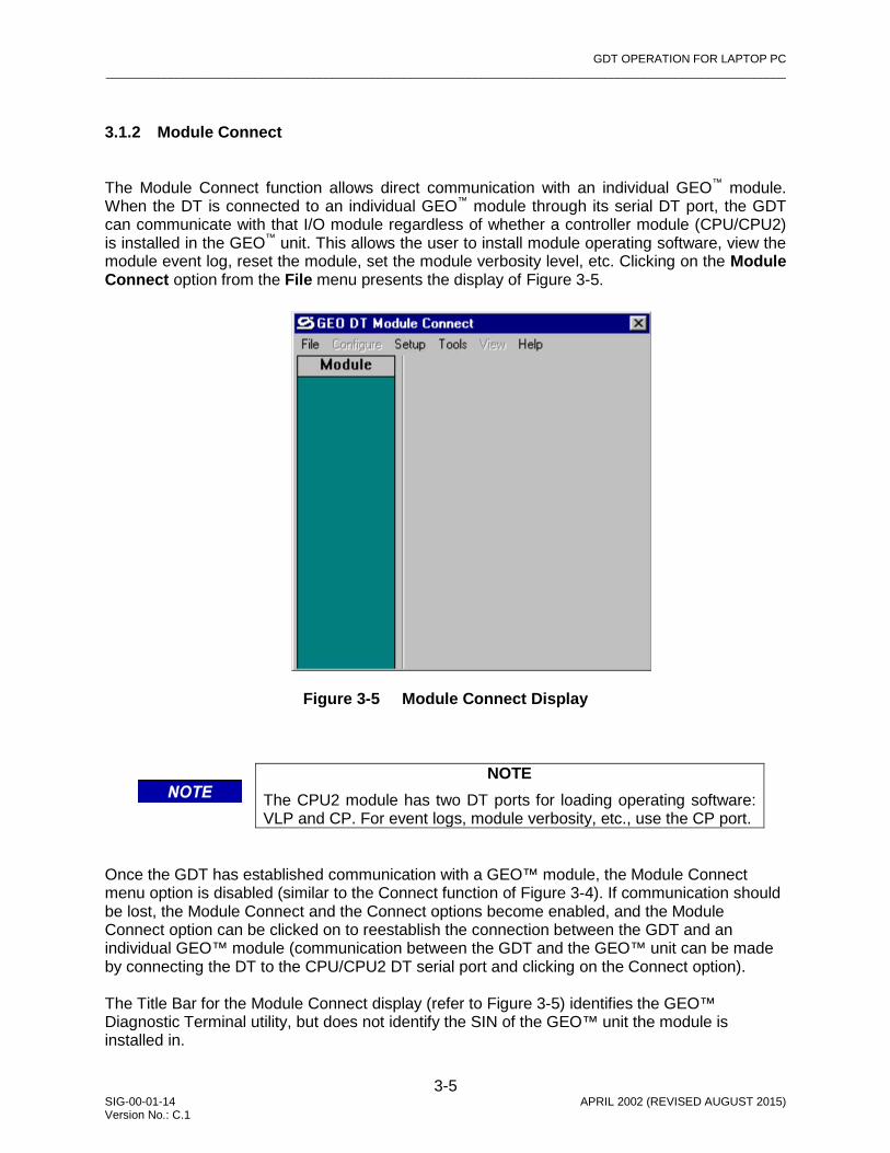
3.1.2 Module Connect The Module Connect function allows direct communication with an individual GEO™ module. When the DT is connected to an individual GEO™ module through its serial DT port, the GDT can communicate with that I/O module regardless of whether a controller module (CPU/CPU2) is installed in the GEO™ unit. This allows the user to install module operating software, view the module event log, reset the module, set the module verbosity level, etc. Clicking on the Module Connect option from the File menu presents the display of Figure 3-5.
Figure 3-5 Module Connect Display
NOTE
The CPU2 module has two DT ports for loading operating software: VLP and CP. For event logs, module verbosity, etc., use the CP port.
Once the GDT has established communication with a GEO™ module, the Module Connect menu option is disabled (similar to the Connect function of Figure 3-4). If communication should be lost, the Module Connect and the Connect options become enabled, and the Module Connect option can be clicked on to reestablish the connection between the GDT and an individual GEO™ module (communication between the GDT and the GEO™ unit can be made by connecting the DT to the CPU/CPU2 DT serial port and clicking on the Connect option). The Title Bar for the Module Connect display (refer to Figure 3-5) identifies the GEO™ Diagnostic Terminal utility, but does not identify the SIN of the GEO™ unit the module is installed in.

GDT OPERATION FOR LAPTOP PC _________________________________________________________________________________________________________
3-6 SIG-00-01-14 APRIL 2002 (REVISED AUGUST 2015) Version No.: C.1
The Menu Bar for the Module Connect display (compare Figure 3-5 to Figure 3-3) provides the same pull-down menus as the Connect function display (refer to paragraphs 3.1 through 3.6 as indicated in Table 3-1 for descriptions of the menu options), except that the “Configure” option and the “View” option are disabled. The Module Slot area for the Module Connect display (refer to Figure 3-5) only identifies that a module is being communicated with, and does not display any status indicators for the slot. Right-clicking on the module label displays the module menu options: Configuration Parameters, Operating Parameters, Event History, Reset, Set Verbosity, Card Information (same as for the Connect function display), except that the “Configuration Parameters”, “Operating parameters”, and “Card information” options are disabled). Refer to paragraphs 3.7.1.1 through 3.7.1.6 for descriptions of the menu options.
3.1.2.1 Loading a New Module MEF A Module Executable File (MEF) can be changed or reloaded when necessary. Instances would be when the hardware and the MEF are not compatible, or when a later version MEF is desired.
NOTE
For the following example, the VLP will be loaded on a CPU2 module.
The procedure for loading the module MEF is as follows: 1. To access the Setup Program, right-click on the module label and select “Reset” from the
options, or select “Reset Module” from the File menu for a CPU/CPU2 module. 2. A confirmation prompt appears (Figure 3-6).
Figure 3-6 Reset Module Confirmation Prompt
3. Click on Yes to proceed with the reboot. The text terminal screen is displayed (Figure 3-7), scrolling data in the text field as it is received from GEO module.

GDT OPERATION FOR LAPTOP PC _________________________________________________________________________________________________________
3-7 SIG-00-01-14 APRIL 2002 (REVISED AUGUST 2015) Version No.: C.1
Figure 3-7 Typical Module Boot Screen
4. When the “Change module setup (Y/N)?” prompt appears in the text terminal screen (refer
to Figure 3-7), quickly click on the Yes button at the top of the screen (before the watchdog timer can time out and continue with bootup).
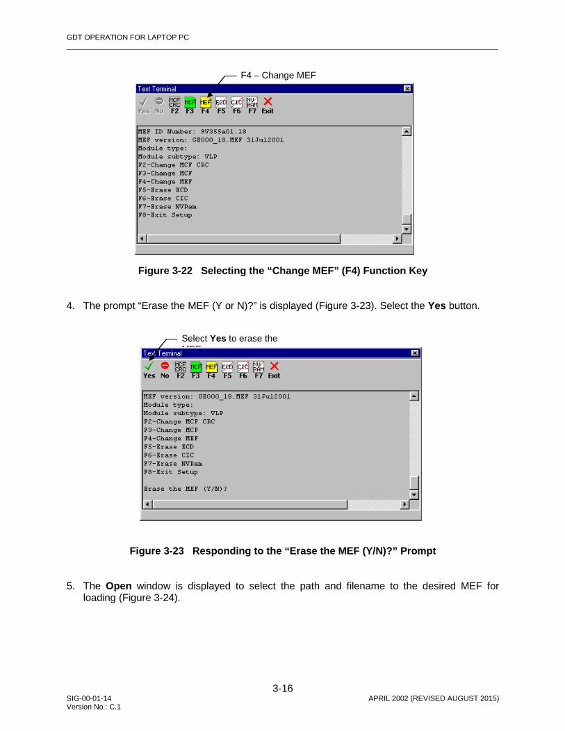
5. A boot screen similar to Figure 3-8 appears. Notice that all Function Key options are
disabled except for F4 (Change MEF) and the Exit button (F8).
Figure 3-8 Selecting the “Change MEF” (F4) Function Key
6. From the Function Key options, select F4 (Change MEF). 7. The prompt “Erase the MEF (Y or N)?” is displayed (Figure 3-9). Select the Yes button.
“Change module setup (Y/N)?” statement
F4 – Change MEF

GDT OPERATION FOR LAPTOP PC _________________________________________________________________________________________________________
3-8 SIG-00-01-14 APRIL 2002 (REVISED AUGUST 2015) Version No.: C.1
Figure 3-9 Responding to the “Erase the MEF (Y/N)? Prompt
8. The Open window is displayed to select the path and filename to the desired MEF for
loading (Figure 3-10).
Figure 3-10 Selecting the MEF to Load
9. Select the MEF to load (.mef extension) and select Open. 10. The Text Terminal screen displays “Erasing the Flash MEF area…” followed by
“Downloading and burning the MEF (ESC to cancel)”, and refreshes the screen with the current configuration data (Figure 3-11). Notice that all Function Key options are disabled except for F4 (Change MEF) and the Exit button (F8).
Select Yes to erase the MEF

GDT OPERATION FOR LAPTOP PC _________________________________________________________________________________________________________
3-9 SIG-00-01-14 APRIL 2002 (REVISED AUGUST 2015) Version No.: C.1
Figure 3-11 Erasing, Downloading, and Burning the MEF
11. Select the Exit button to exit setup. “Setup Finished” is displayed in the Text Terminal
screen (see Figure 3-12), then the screen refreshes with the current configuration data, then the CPU/CPU2 module reboots.
Figure 3-12 Setup Finished Screen
12. Select the Exit button again to close the Text Terminal screen. The main GDT screen
refreshes. Optional: To verify that the proper MEF is loaded in the GEO module, select the “Card Information” option for the slot during a normal DT session using the CPU/CPU2 module DT serial port (when using the Connect function). Note that Card Information is only available when the GDT is communicating with the GEO unit through the VLP serial DT port of the CPU module or the CP serial DT port of the CPU2 module, and not by using the I/O Module Connect function.

GDT OPERATION FOR LAPTOP PC _________________________________________________________________________________________________________
3-10 SIG-00-01-14 APRIL 2002 (REVISED AUGUST 2015) Version No.: C.1
3.1.2.2 Viewing the Module Event Log Each GEO module records its functional events in its own event log. Selecting the “Event History” function from the pop-up menu for a slot (by right-clicking on the label for the module) provides a display of the Online log from the GEO unit similar to that in Figure 3-13.
Figure 3-13 Typical Online Module Event History Display
NOTE
When the DT is in session directly with a GEO™ module (using Module Connect), the Title Bar for the display reads “Local” (refer to Figure 3-13).
All of the usual Navigation, Save, Download, Delete, Source and Format buttons for viewing and managing history logs are active. Refer to paragraph 3.7.1.3, Event History, for a description of Online and Offline logs and downloading, filtering, editing, saving and deleting of logs.
3.1.2.3 Setting Module Verbosity Setting a module’s verbosity level directly while using the Module Connect function is almost the same as setting it while communicating normally through the CPU/CPU2 module DT serial port (using the Connect function). The only difference is that the current value of verbosity is not available when the DT is in direct session with a module. When “Set Verbosity” is selected in this case, a warning screen is displayed (Figure 3-14) to remind the user that the current setting cannot be viewed.

GDT OPERATION FOR LAPTOP PC _________________________________________________________________________________________________________
3-11 SIG-00-01-14 APRIL 2002 (REVISED AUGUST 2015) Version No.: C.1
Figure 3-14 Verbosity Warning Screen
Click on OK to proceed. The Module Verbosity screen is displayed identifying the slot number (Figure 3-15).
NOTE
The displayed position of the slider (Min) probably does not represent the current setting when using the Module Connect function.
Figure 3-15 Module Verbosity Screen
If it is decided not to change or set the verbosity level, click on the Exit button (unless the Set button is clicked on, the current verbosity levels will not be changed). To set the verbosity level, move the slider to the desired position. The “Min” position relates to level 1 and the “Max” position relates to level 5. Detents are provided on the slider for the intermediate positions. When the slider is at the desired level, click on the Set button to activate the setting. Click on the Exit button to close the screen.

GDT OPERATION FOR LAPTOP PC _________________________________________________________________________________________________________
3-12 SIG-00-01-14 APRIL 2002 (REVISED AUGUST 2015) Version No.: C.1
3.1.3 Disconnect When GDT communication has been established (either with a GEO™ unit or with an individual GEO™ module), the Disconnect function becomes enabled on the options of the File menu on the GDT screen (see Figure 3-4) and can be clicked on to break the connection between the GDT and the GEO™ unit or an individual module. The Disconnect function is disabled once communication is lost, and the module assignment display of Figure 3-3 is replaced with the screen of Figure 3-16.
Figure 3-16 DT Screen when Communication is Broken
From the File menu, use either the Connect option (communicate with a GEO unit) or the Module Connect option (communicate with a GEO™ module) to reconnect. If the utility fails to re-establish communication, the screen changes to that of Figure 3-17. Notice that the Configure and View menus are disabled when there is no communication.
Figure 3-17 DT Screen when Communication Cannot be Re-established
3.1.4 Reset Module The CPU/CPU2 module may be reset at any time by the user via the GDT Reset function (or by recycling power to the GEO™ unit). A reset may be done to force a reboot, or to allow the user to enter the setup program from the Bootstrap Text Terminal screen.

GDT OPERATION FOR LAPTOP PC _________________________________________________________________________________________________________
3-13 SIG-00-01-14 APRIL 2002 (REVISED AUGUST 2015) Version No.: C.1
To reboot the CPU module in the GEO™ wayside unit, click on the Reset Module function of the File menu (or right-click on the label for the VLP/VLP2 module in slot 1 and select Reset). A confirmation prompt appears (Figure 3-18).
Figure 3-18 Reset Module Confirmation Prompt Click on Yes to proceed with the reboot. A bootstrap text terminal screen similar to Figure 3-19 appears. The information displayed in the text field scrolls as data is received from the GEO™ unit.
Figure 3-19 Initial Bootstrap Text Terminal Screen
NOTE
During the reboot, communication is terminated between the GDT and the GEO™ CPU, and “Rebooting” appears on the GDT screen. If the GDT times out during the reboot, “No Response” appears on the GDT screen (refer to Figure 3-17). After the CPU returns to normal operation, reestablish communication as described in paragraph 3.1.1.

GDT OPERATION FOR LAPTOP PC _________________________________________________________________________________________________________
3-14 SIG-00-01-14 APRIL 2002 (REVISED AUGUST 2015) Version No.: C.1
The scrolling pauses briefly when the SIN is displayed, then the screen changes to that of Figure 3-20 as current setup data is displayed.
Figure 3-20 Typical CPU Boot Screen When the “Change module setup (Y/N)?” statement appears (see Figure 3-20), the display pauses again and the Yes and No buttons at the top left corner of the display are enabled. If setup needs to be changed, be ready to click on the Yes button as soon as the statement appears (before the watchdog timer can time out). Make setup changes as described in the following paragraphs. If No is clicked on (or if neither button is clicked on), the setup watchdog timer times out (in 4 to 5 seconds) and the CPU assumes the current setup values (shown in Figure 3-19 and Figure 3-20) and finishes rebooting using these values. Wait for the display to stop scrolling, then click on the Exit button to close this display. If the Yes button is clicked on, the screen changes to the Change Setup Screen displaying the list of edit options (see Figure 3-21), and the function keys at the top of the display (labeled F2 through F7) become enabled. These options and their corresponding buttons are listed below.
Yes/No Buttons
Setup Function Keys (disabled)
Exit Button (F8)
“Change module setup (Y/N)?” statement
Erase CIC
Erase NVRam
Change MCF Change MEF Change MCF CRC
Erase ECD

GDT OPERATION FOR LAPTOP PC _________________________________________________________________________________________________________
3-15 SIG-00-01-14 APRIL 2002 (REVISED AUGUST 2015) Version No.: C.1
NOTE
The “F8 – Exit setup” function key corresponds to the Exit button.
Figure 3-21 Change Setup Screen
Following any setup editing, the system will reboot. Refer to paragraphs 3.1.4.1 through 3.1.4.6 for using the setup editing function keys, or refer to paragraph 3.1.4.7 for exiting the setup program.
3.1.4.1 Loading a New MEF (F4) The CPU/CPU2 Module Executable File (MEF) can be changed or reloaded when necessary. Instances would be when the hardware and the MEF are not compatible, or when a later version MEF is desired. The procedure for loading the MEF is as follows: 1. To access the Setup Program, reset the CPU/CPU2 module (refer to paragraph 3.1.4 for the
reset module procedure). 2. When the “Change module setup (Y/N)?” prompt appears in the text terminal screen (refer
to Figure 3-20), quickly click on the Yes button at the top of the screen (before the watchdog timer can time out and continue with bootup).
3. A boot screen similar to Figure 3-22 appears. From the Function Key options, select F4
(Change MEF).
GDT OPERATION FOR LAPTOP PC _________________________________________________________________________________________________________
3-16 SIG-00-01-14 APRIL 2002 (REVISED AUGUST 2015) Version No.: C.1
Figure 3-22 Selecting the “Change MEF” (F4) Function Key 4. The prompt “Erase the MEF (Y or N)?” is displayed (Figure 3-23). Select the Yes button.
Figure 3-23 Responding to the “Erase the MEF (Y/N)?” Prompt
5. The Open window is displayed to select the path and filename to the desired MEF for
loading (Figure 3-24).
F4 – Change MEF
Select Yes to erase the MEF

GDT OPERATION FOR LAPTOP PC _________________________________________________________________________________________________________
3-17 SIG-00-01-14 APRIL 2002 (REVISED AUGUST 2015) Version No.: C.1
Figure 3-24 Selecting the MEF to Load
6. Select the MEF to load (.mef extension) and select Open. 7. The Text Terminal screen displays “Erasing the Flash MEF area…” followed by
“Downloading and burning the MEF (ESC to cancel)”, and refreshes the screen with the current configuration data (Figure 3-25) (note that the F2 and F3 Function Keys are disabled for the GDT).
Figure 3-25 Erasing, Downloading, and Burning the MEF
8. Select the Exit button to exit setup. “Setup Finished” is displayed in the Text Terminal
screen, the screen refreshes with the current configuration data, and the CPU/CPU2 module reboots.
9. Select the Exit button again to close the Text Terminal screen. The main GDT screen
refreshes. Optional: To verify that the proper MEF is loaded in the GEO unit, from the View menu, select “CPU Version”, or right-click on the VLP/VLP2 label and select “Card Information”.

GDT OPERATION FOR LAPTOP PC _________________________________________________________________________________________________________
3-18 SIG-00-01-14 APRIL 2002 (REVISED AUGUST 2015) Version No.: C.1
3.1.4.2 Loading a New MEF (F3) The procedure for loading the MCF is as follows: 1. To access the Setup Program, reset the CPU/CPU2 module (refer to paragraph 3.1.4 for the
reset module procedure). 2. When the “Change module setup (Y/N)?” prompt appears in the text terminal screen (refer
to Figure 3-20), quickly click on the Yes button at the top of the screen (before the watchdog timer can time out and continue with bootup).
3. A boot screen similar to Figure 3-26 appears listing the Function Key options.
Figure 3-26 Select the “Change MCF” (F3) Function Key 4. Select F3 (Change MCF). The Open window is displayed to select the path and filename to
the desired MCF (Figure 3-27). The .mcf file may be stored on the PC, or it may be on CDROM, thumb-drive, etc. Be sure to locate the proper MCF CRC for the MCF to be loaded (required after loading an MCF).
F3 – Change MCF

GDT OPERATION FOR LAPTOP PC _________________________________________________________________________________________________________
3-19 SIG-00-01-14 APRIL 2002 (REVISED AUGUST 2015) Version No.: C.1
Figure 3-27 Browsing for the MCF to Load
5. Select the MCF to load (.mcf extension) and select Open. 6. The Text Terminal screen displays “Downloading the MCF (ESC to cancel)” as the 4-
character display on the GEO unit CPU/CPU2 module reads “BOOT” (refer to the Text Terminal screen detail below). Wait as the Checksums are compared.
7. The Text Terminal screen displays “MCF Checksum OK” (refer to the Text Terminal screen
detail below) as the 4-character display on the GEO unit CPU/CPU2 module sweeps a zero back and forth. Wait as the Setup Program prepares to burn the MCF in the ECD.
8. The Text Terminal screen displays “Burning the MCF…” (refer to the Text Terminal screen
detail below) as the 4-character display on the GEO unit CPU/CPU2 module reads “BOOT”.
9. The Text Terminal screen displays “Verifying MCF in ECD…” (refer to the Text Terminal
screen detail below) as the 4-character display on the GEO unit CPU/CPU2 module reads “BOOT”.
10. The Text Terminal screen displays “MCF Verified OK.” (refer to the Text Terminal screen
detail below) as the 4-character display on the GEO unit CPU/CPU2 module reads “BOOT”.
11. The Text Terminal screen refreshes and displays the Function Key options (refer to Figure
3-26) as the 4-character display on the GEO unit CPU/CPU2 module reads “BOOT”. 12. At this point the MCF CRC must be set. Proceed to paragraph 3.1.4.3 for MCF CRC setup.

GDT OPERATION FOR LAPTOP PC _________________________________________________________________________________________________________
3-20 SIG-00-01-14 APRIL 2002 (REVISED AUGUST 2015) Version No.: C.1
3.1.4.3 Setting the MCF CRC (F2) The procedure for setting the MCF CRC is as follows: 1. After the MCF was downloaded and verified (paragraph 3.1.4.2), the function keys are again
displayed (refer to Figure 3-26). The boot up of the GEO unit cannot complete until the MCF CRC is entered.
2. The current MCF CRC is invalidated after downloading a new MCF, and the MCF CRC
supplied with the new MCF must be entered. However, if the same MCF was reloaded, the MCF CRC does not change, but it must still be entered using this procedure.
NOTE
The MCF CRC is supplied with the MCF. If the previous MCF was reloaded, the same MCF CRC can be entered. The previously loaded MCF CRC can be viewed by using the scroll bar on the Text Terminal screen to scroll up until the MCF CRC is viewable (Figure 3-28).
Figure 3-28 Scrolling up to View the Previous MCF CRC
3. On the Text Terminal screen, select F2 (Change MCF CRC). 4. The MCFCRC window is displayed (Figure 3-29).
Previous MCF CRC

GDT OPERATION FOR LAPTOP PC _________________________________________________________________________________________________________
3-21 SIG-00-01-14 APRIL 2002 (REVISED AUGUST 2015) Version No.: C.1
Figure 3-29 MCFCRC Window 5. Type in the correct 8-digit hexadecimal number for the MCF CRC and select OK. 6. The Text Terminal screen displays “Enter the field CRC in hex (ESC to cancel):” followed by
the 8 digit hexadecimal number just entered, then the Text Terminal screen refreshes once again.
7. Select the Exit button (F8) to finish setup. The Text Terminal screen displays “Setup
Finished” (Figure 3-30), and then refreshes to display configuration data followed by the Function Key options.
Figure 3-30 Setup Finished Window 8. Select the Exit button (F8) again to close the Text Terminal window. The GEO unit
continues with the bootup process, displaying in order: BOOT, INIT, LMCF, ICHK, and then scrolling the MCF version unless error messages are displayed (if a different MCF was loaded, error messages will most likely be displayed. Refer to Figure 3-85 later in this section for a flow diagram for resolving setup errors).

GDT OPERATION FOR LAPTOP PC _________________________________________________________________________________________________________
3-22 SIG-00-01-14 APRIL 2002 (REVISED AUGUST 2015) Version No.: C.1
3.1.4.4 Erasing the ECD (F5)
NOTE
This function is only to be used for recovery in the event that corruption occurs in the ECD. A loss of MCF will result by erasing the ECD.
The procedure for erasing the ECD is as follows: 1. To access the Setup Program, reset the CPU/CPU2 module (refer to paragraph 3.1.4 for the
reset module procedure). 2. When the “Change module setup (Y/N)?” prompt appears in the text terminal screen (refer
to Figure 3-20), quickly click on the Yes button at the top of the screen (before the watchdog timer can time out and continue with bootup).
3. A boot screen similar to Figure 3-31 appears. From the Function Key options, select F5
(Erase ECD).
Figure 3-31 Selecting the “Erase ECD” (F5) Function Key
4. The prompt “Erase the ECD (Y or N)?” is displayed (Figure 3-32). Select the Yes button.
F5 – Erase ECD

GDT OPERATION FOR LAPTOP PC _________________________________________________________________________________________________________
3-23 SIG-00-01-14 APRIL 2002 (REVISED AUGUST 2015) Version No.: C.1
Figure 3-32 Responding to the “Erase the ECD (Y/N)?” Prompt 5. The system responds by displaying “Erasing the ECD” (refer to Figure 3-33), as the
CPU/CPU2 module in the GEO unit sweeps a zero back and forth across the 4-character display.
6. When the ECD has been erased, the message “ECD Cleared” (refer to Figure 3-33) is
displayed on the Text Terminal screen as the 4-character display on the GEO unit CPU/CPU2 module reads “BOOT”.
Figure 3-33 ECD Cleared
Select Yes to erase the ECD

GDT OPERATION FOR LAPTOP PC _________________________________________________________________________________________________________
3-24 SIG-00-01-14 APRIL 2002 (REVISED AUGUST 2015) Version No.: C.1
7. The Text Terminal screen refreshes and displays the Function Keys.
8. At this point the system is without an MCF. Select F3 (Change MCF) from the Function Key options to reload the MCF, and follow the procedure in paragraph 3.1.4.2, Loading a New MCF.
3.1.4.5 Erasing the CIC (F6)
NOTE
This function is only to be used for recovery in the event that corruption occurs in the CIC. A loss of Operating Parameters, UCN, MCF CRC, and SIN will result by erasing the CIC.
The procedure for erasing the CIC is as follows: 1. To access the Setup Program, reset the CPU/CPU2 module (refer to paragraph 3.1.4 for the
reset module procedure). 2. When the “Change module setup (Y/N)?” prompt appears in the text terminal screen (refer
to Figure 3-20), quickly click on the Yes button at the top of the screen (before the watchdog timer can time out and continue with bootup).
3. A boot screen similar to Figure 3-34 appears. From the Function Key options, select F6
(Erase CIC).
Figure 3-34 Selecting “Erase CIC” (F6) Function Key
F6 – Erase CIC

GDT OPERATION FOR LAPTOP PC _________________________________________________________________________________________________________
3-25 SIG-00-01-14 APRIL 2002 (REVISED AUGUST 2015) Version No.: C.1
4. The prompt “Erase the CIC (Y or N)?” is displayed (Figure 3-35). Select the Yes button.
Figure 3-35 Responding to the “Erase the CIC (Y/N)?” Prompt
5. The system responds by displaying “Clearing CIC” (refer to Figure 3-36), as the CPU/CPU2
module in the GEO unit sweeps an asterisk back and forth across the 4-character display.
Figure 3-36 CIC Cleared
6. When the CIC has been erased, the message “CIC Cleared” (refer to Figure 3-36) is
displayed on the Text Terminal screen as the 4-character display on the GEO™ unit CPU/CPU2 module reads “BOOT”.
7. The Text Terminal screen refreshes and displays the Function Keys. 8. Click on Exit to exit the Setup program and allow the system to continue with bootup.
Select Yes to erase the CIC

GDT OPERATION FOR LAPTOP PC _________________________________________________________________________________________________________
3-26 SIG-00-01-14 APRIL 2002 (REVISED AUGUST 2015) Version No.: C.1
9. After bootup completes, perform module setup procedures to clear error messages for
Configuration parameters (paragraph 3.7.1.1), Operating Parameters (paragraph 3.7.1.2), Vital User Options (paragraph 3.2.1), Non-vital User Options (paragraph 3.2.2), Vital User I/O (paragraph 3.2.3), Non-vital User I/O (paragraph 3.2.4), Vital User Timers (paragraph 3.2.5), Non-vital User Timers (paragraph 3.2.6), CRC (paragraph 3.1.4.3), and UCN (paragraph 3.2.8).
3.1.4.6 Erasing the NVRAM (F7)
NOTE
This function is only to be used for recovery in the event that corruption occurs in the Non-volatile RAM. A loss of Event Log will result by erasing the NVRAM.
The procedure for erasing the NVRAM is as follows: 1. To access the Setup Program, reset the CPU/CPU2 module (refer to paragraph 3.1.4 for the
reset module procedure). 2. When the “Change module setup (Y/N)?” prompt appears in the text terminal screen (refer
to Figure 3-20), quickly click on the Yes button at the top of the screen (before the watchdog timer can time out and continue with bootup).
3. A boot screen similar to Figure 3-37 appears. From the Function Key options, select F7
(Erase NVRAM).
Figure 3-37 Selecting the “Erase NVRAM” (F7) Function Key
F7 – Erase NVRAM

GDT OPERATION FOR LAPTOP PC _________________________________________________________________________________________________________
3-27 SIG-00-01-14 APRIL 2002 (REVISED AUGUST 2015) Version No.: C.1
4. The prompt “Erase the NVRAM (Y or N)?” is displayed (Figure 3-38). Select the Yes button.
Figure 3-38 Responding to the “Erase the NVRAM (Y/N)” Prompt 5. When the NVRAM has been cleared, the Text Terminal screen displays “NVRam Cleared”
(refer to Figure 3-39).
Figure 3-39 Clearing the NVRAM
6. The Text Terminal screen refreshes and displays the Function Key options as the 4-
character display on the GEO unit CPU/CPU2 module reads “BOOT”. 7. Click on Exit to exit the Setup program and allow the system to continue with bootup.
Select Yes to erase the NVRAM

GDT OPERATION FOR LAPTOP PC _________________________________________________________________________________________________________
3-28 SIG-00-01-14 APRIL 2002 (REVISED AUGUST 2015) Version No.: C.1
3.1.4.7 Exitng the Setup Program (F8)
Select the Exit button to close the setup program. A screen similar to Figure 3-40 is displayed as the data is refreshed.
Figure 3-40 Setup Finshed Screen
The data in the Setup Finished screen is identical to the data that will appear in the initial Bootstrap Text Terminal screen the next time the CPU/CPU2 module is reset. 3.1.5 Exit Click on the Exit function to exit the GDT utility. Communication with the GEO™ wayside unit or with an individual GEO™ module is broken.
3.2 CONFIGURE MENU
The Configure menu contains the functions listed below and described in the following paragraphs. • Vital User Options • Nonvital User I/O • Set SIN • Delete MCF • Nonvital User Options • Vital User Timers • Set UCN • Vital User I/O • Nonvital User Timers • Set Time
3.2.1 Vital User Options
NOTE
Vital User Options can only be viewed or changed by using the GDT utility.

GDT OPERATION FOR LAPTOP PC _________________________________________________________________________________________________________
3-29 SIG-00-01-14 APRIL 2002 (REVISED AUGUST 2015) Version No.: C.1
If a Vital User Option is not confirmed on startup or after a change of MCF, the system stays unconfigured and an ERR: VOP is displayed until corrected (vital option error). The system becomes fully operational after the VOP error is cleared and the system is reset. An example of a Vital User Option is an MCF that allows selecting either a steady yellow or a flashing yellow aspect. The user can choose which aspect is applicable for the location and set it in the field. Vital User Options are protected by the UCN (Unique Check Number), therefore, if the Vital User Options are changed, the Installer/Maintainer must enter the applicable UCN for these options and then reboot. If the UCN is incorrect, the GEO system boots up unconfigured.
WARNING
SETTING VITAL USER OPTIONS INCOR-RECTLY COULD RESULT IN A HAZARDOUS EVENT. ALWAYS VERIFY VITAL OPTION CHANGES AFTER COMPLETING THE VITAL OPTION CHANGE PROCESS. THE IMPLEMENTATION OF VITAL USER OPTION CHANGES AND THEIR EFFECTS ON RAILROAD SAFETY ARE THE RESPONSIBILITY OF THE GDT USER.
WARNING WHEN CHANGING VITAL USER OPTIONS, THE ENTIRE LOCATION AND ANY FUNCTIONS AFFECTED BY THAT CHANGE MUST BE THOROUGHLY RETESTED IN ACCORDANCE WITH FRA REGULATIONS.
WARNING A SYSTEM REBOOT COULD OCCUR AT ANY TIME DURING THE VITAL USER OPTION CHANGE PROCESS. CAREFULLY MONITOR USER INTER¬FACE INDICATORS TO DETECT A REBOOT. IF A REBOOT OCCURS BEFORE THE CHANGE PROCESS IS COMPLETE, THE ORIGINAL VITAL OPTION VALUES WILL REMAIN IN EFFECT UNLESS CHANGES WERE UPLOADED TO THE CIC.

GDT OPERATION FOR LAPTOP PC _________________________________________________________________________________________________________
3-30 SIG-00-01-14 APRIL 2002 (REVISED AUGUST 2015) Version No.: C.1
NOTE
If a reboot occurs during reprogramming of the CIC, option value changes could be corrupted. This will be detected by the UCN check performed by the GEO™ unit during reboot.
NOTE
There are two phases to the process of changing Vital User Options; 1) entering the change, and 2) providing a valid UCN to enable uploading the change to the CIC and rebooting the GEO™ unit to allow the changes to take effect.
The GDT procedure for changing the Vital User Options is as follows: 1. Bring up the Vital User Options screen (Configure menu/Vital User Options). The display
will be similar to the one shown in Figure 3-41.
Figure 3-41 Typical Vital User Options Configuration Display with Current Values
2. The current settings of the parameters are listed in the Value column (click on the Current
Options button at the top of the screen to refresh the current options). The current values are also displayed in the “Verify” list box immediately below the options box. The values in the Value field must match the values in the “Verify” list box.

GDT OPERATION FOR LAPTOP PC _________________________________________________________________________________________________________
3-31 SIG-00-01-14 APRIL 2002 (REVISED AUGUST 2015) Version No.: C.1
NOTE
If the current values do not appear on the “Vital User Options” display, select the Cancel button to enable the Current button, and then select the Current button to display the current values. The current values are what the GEO™ unit is currently operating with and are stored in the CIC.
3. Click on the Value field of the desired option to display the drop-down list control box (see detail below).
4. In the control box, click on the down arrow button ( τ ) to display the options list. The current
selection is highlighted. 5. Click on the desired option from the drop-down list (e.g., True, False) to highlight it.
NOTE
The available values for the Vital User Options depend on the type of Vital User Option selected (established in MCF).
6. The drop-down list closes. Verify that the desired option is now displayed in the Value field. 7. Make any other option changes as desired. 8. After all value changes are completed using the process just described, click on Apply at
the top of the Vital User Options screen. The GDT sends the changes to the GEO unit which processes the changes and then returns data that is displayed in the GDT “Verify” list box (see Figure 3-42). Note that the Apply button is disabled after being clicked on.

GDT OPERATION FOR LAPTOP PC _________________________________________________________________________________________________________
3-32 SIG-00-01-14 APRIL 2002 (REVISED AUGUST 2015) Version No.: C.1
Figure 3-42 Typical Vital User Options Configuration Display after Initial Changes
WARNING COMPARE THE NEW VALUES IN THE “VALUE” COLUMN WITH THE CORRESPONDING VALUES IN THE “VERIFY” LIST BOX; THEY MUST MATCH AND ONLY THE DESIRED CHANGES SHOULD BE LISTED. ALSO VERIFY THAT THE “NUMBER OF CHANGES” CORRESPONDS TO THE NUMBER OF OPTION VALUES CHANGED. IF ANYTHING IS INCORRECT, CANCEL THE PROCESS SINCE AN ERROR HAS OCCURRED.
NOTE
Number of changes refers to the number of current values held by the CPU (CIC) that have been changed in the “Value” column.
9. To prepare the changes for acceptance, scroll down the information in the “Verify” list box
and check the listed changes to verify that they are correct. If the changes are not correct, select the Cancel button and reenter the changes.
10. If the changes are correct, scroll down until the Confirmation CRC value is displayed and
then enter this value in the “CRC” text box immediately below the “Verify” list box (Figure 3-43). Entering the CRC ensures that the changes are confirmed with the GEO unit. This entry is not case sensitive.

GDT OPERATION FOR LAPTOP PC _________________________________________________________________________________________________________
3-33 SIG-00-01-14 APRIL 2002 (REVISED AUGUST 2015) Version No.: C.1
Figure 3-43 Typical Vital User Options Config Display with Confirmation CRC Entered
11. Click on the Accept button at the top of the display to finalize the changes. After the changes are accepted, the phrase “Changes succeeded” appears below the CRC text box (see Figure 3-44). The changes are now held internally by the GEO™ unit but have not been applied and have not been enforced in the CIC. Note that the Accept button is disabled after being clicked on.
Figure 3-44 Typical Vital User Config Display with “Changes succeeded” Statement

GDT OPERATION FOR LAPTOP PC _________________________________________________________________________________________________________
3-34 SIG-00-01-14 APRIL 2002 (REVISED AUGUST 2015) Version No.: C.1
NOTE
At this point in the change process, changes have not yet been uploaded to the GEO™ CIC, and additional changes can be made. If the Cancel button is selected at any time during this first phase, the pending changes are erased.
NOTE
If “Changes failed” appears when the Accept button is selected, verify that the correct CRC was entered. If not, correct the CRC and select Accept again. If “Changes failed” is displayed again, cancel the changes and repeat the change process. If the changes fail again, reset the CPU and repeat the change process.
12. The changes that were made are now in the “pending” state, and will not become active until
a new UCN has been entered and the system rebooted.
NOTE
Do not select the Cancel button unless the changes just entered on this display are to be cancelled. If the Cancel button was selected at any time during the first phase of the change process after new values were entered (effects value changes on current display only), no pending values will be displayed when the Pending button is selected and the statement “No Changes Pending” will appear in the “Verify” list box (see Figure 3-45).
NOTE
Pending changes are the changes made to the current values. To view pending changes before proceeding, select the Pending button at the top of the display. If Vital User Options are pending, they are listed in the “Pending Options” column, and their values are displayed in the “Value” column (refer to Figure 3-45).

GDT OPERATION FOR LAPTOP PC _________________________________________________________________________________________________________
3-35 SIG-00-01-14 APRIL 2002 (REVISED AUGUST 2015) Version No.: C.1
Figure 3-45 Typical Vital User Options Config Display with “No Changes Pending”
Statement
13. To make the Vital User Option changes valid, it is necessary to enter a valid UCN and then
reboot the system to enable the upload of the changes to the GEO™ CIC. Refer to paragraph 3.2.8 for instructions on setting the UCN and rebooting the CPU/CPU2 module.
NOTE
When Vital Configuration Parameters are changed or a confirmation CRC is entered, a 30 minute timer is started. If the timer times out (by not setting the UCN and rebooting), the changes are discarded. This timer prevents a user from making changes and leaving them in the pending state for an extended period of time. While in the pending state, the changes are not acted upon by the GEO™ unit.
3.2.2 Non-Vital User Options
An example of a Non-vital User Option is the ability to change how a track Code 5 is sent (refer to Table 3-2 for a typical example).

GDT OPERATION FOR LAPTOP PC _________________________________________________________________________________________________________
3-36 SIG-00-01-14 APRIL 2002 (REVISED AUGUST 2015) Version No.: C.1
CAUTION
SETTING NON-VITAL USER OPTIONS INCORRECTLY COULD RESULT IN A SYSTEM THAT IS NOT FULLY OPERATIONAL. THE RAILROAD ASSUMES RESPONSIBILITY FOR ITS FIELD-CONFIGURED NON-VITAL USER OPTIONS.
Table 3-2 Field Configurable Non-Vital User Options – Typical Example
Option Option Label EC5[1]
Description Option
Label WC5[1]
Description
Repeat RPT Repeat Code 5 Eastbound when a Code 5 is received from the West
RPT Repeat Code 5 Westbound when a Code 5 is received from the East
On C1 C1 Send a Code 5 Eastbound when a Code 1 is received from the West
C1 Send a Code 5 Westbound when a Code 1 is received from the East
Off OFF Never send a Code 5 East OFF Never send a Code 5 West On ON Always send a Code 5 East ON Always send a Code 5 West
[1] These labels are seen on the 4-character display of the CPU/CPU2 module when viewing or changing OPT# using the Sel and Nav push buttons.
If a Non-vital User Option is not confirmed on startup or after a change of MCF, the system becomes operational using the default values of the options set by the MCF, but an ERR: NOP is displayed (non-vital option error) until changed or confirmed. Non-vital User Options can be changed during normal operation without requiring confirmation, UCN entry, or rebooting the CPU/CPU2 module as is required with changing Vital User Options (refer to paragraph 3.2.1 for Vital User Options).
NOTE
Non–vital User Options may be set up by using either the GDT or the Maintainers Interface.
The GDT procedure for setting the Non-vital User Options is as follows: 1. Bring up the Non-vital User Options screen (Configure menu/Non-vital User Options).
Figure 3-46 presents a typical Non-vital User Options screen. This display enables the user to initiate a change of the Non-vital User Options defined in the MCF and stored in the CIC.

GDT OPERATION FOR LAPTOP PC _________________________________________________________________________________________________________
3-37 SIG-00-01-14 APRIL 2002 (REVISED AUGUST 2015) Version No.: C.1
Figure 3-46 Typical Non-Vital User Options Config Display with Current Values
2. The current settings of the parameters are listed under the Value column (click on the
Current Options button at the top of the screen to refresh the current options).
NOTE
The current values are what the GEO™ unit is currently operating with and are stored in the CIC.
3. To change a value, select that field in the “Value”
column. A drop-down option box appears in place of the selected value (see drop-down option box at right). Select the down arrow () button in the option box to display the list of available values (current value is highlighted). For the example above, the available values are On C1, Repeat, Off and On. The available values depend on the type of Non-vital User Option selected. Select the desired value from the drop-down list. The drop-down list closes and the newly selected value replaces the former value in the “Value” column.
NOTE
When the change field requires a numeric value, spin buttons automatically appear to allow the values to be incremented/decremented by valid amounts (hold down to change continuously).

GDT OPERATION FOR LAPTOP PC _________________________________________________________________________________________________________
3-38 SIG-00-01-14 APRIL 2002 (REVISED AUGUST 2015) Version No.: C.1
After all value changes are completed using the process just described, select the Apply button at the top of the display. The GDT processes the changes and uploads them to the GEO™ CIC where they become effective immediately. There are no pending values for Non-vital User Options. 3.2.3 Vital User I/O
NOTE
Vital User I/O can only be viewed or changed by using the GDT utility, and changes must be made locally at the site.
An example of a Vital User I/O would be to inject an input to test a crossing controller (e.g., test gates and flashing lights) from the GEO unit. The parameters for the test must be established in the MCF. Vital User I/O are not protected by the UCN (Unique Check Number), therefore, if the Vital User I/O are changed, the Installer/Maintainer is not required to enter the applicable UCN for these options or reboot. Vital User I/O can only be implemented by the user at the local site. To ensure this, the user must press a push button on the CPU/CPU2 module at the location during the procedure.
WARNING SETTING VITAL USER I/O INCOR¬RECTLY COULD RESULT IN A HAZARDOUS EVENT. ALWAYS VERIFY VITAL I/O CHANGES AFTER COMPLETING THE VITAL I/O CHANGE PROCESS. THE IMPLEMENTATION OF VITAL USER I/O CHANGES AND THEIR EFFECTS ON RAILROAD SAFETY ARE THE RESPONSIBILITY OF THE GDT USER.
WARNING AFTER CHANGING VITAL USER I/O, VERIFY THE PROPER STATES OF THE I/O. THE ENTIRE LOCATION AND ANY FUNCTIONS AFFECTED BY THAT CHANGE MUST BE THOROUGHLY RE-TESTED IN ACCORDANCE WITH FRA REGULA-TIONS.

GDT OPERATION FOR LAPTOP PC _________________________________________________________________________________________________________
3-39 SIG-00-01-14 APRIL 2002 (REVISED AUGUST 2015) Version No.: C.1
WARNING
A SYSTEM REBOOT COULD OCCUR AT ANY TIME DURING THE VITAL USER I/O CHANGE PROCESS. CAREFULLY MONITOR USER INTER¬FACE INDICA-TORS TO DETECT A REBOOT. IF A REBOOT OCCURS BEFORE THE CHANGE PROCESS IS COMPLETE, THE ORIGINAL VITAL I/O VALUES WILL REMAIN IN EFFECT UNLESS CHANGES WERE UPLOADED TO THE CIC.
NOTE
If a reboot occurs during reprogramming of the CIC, option value changes could be corrupted. This will be detected by the UCN check performed by the GEO™ unit during reboot.
The GDT procedure for changing the Vital User I/O is as follows: 1. Bring up the Vital User I/O screen (Configure menu/Vital User I/O). The display will be
similar to the one shown in Figure 3-47.
Figure 3-47 Typical Vital User I/O Configuration with Current Values

GDT OPERATION FOR LAPTOP PC _________________________________________________________________________________________________________
3-40 SIG-00-01-14 APRIL 2002 (REVISED AUGUST 2015) Version No.: C.1
2. The current settings of the parameters are listed in the Value column (click on the Current
Options button at the top of the screen to refresh the current options).
NOTE
If the current values do not appear on the “Vital User I/O” display, select the Cancel button to enable the Current button, and then select the Current button to display the current values. The current values are what the GEO™ unit is currently operating with and are stored in the CIC.
The current values are also displayed in the “Verify” list box immediately below the options box. The values in the Value field must match the values in the “Verify” list box.
3. Click on the Value field of the desired option to display the drop-down list control box (see
detail below).
4. In the control box, click on the down arrow button ( τ ) to display the options list. The current
selection is highlighted. 5. Click on the desired option from the drop-down list (e.g., OFF, ON) to highlight it.
NOTE
Available values for the Vital User I/O depend on the type of Vital User I/O selected (established in MCF).
6. The drop-down list closes. Verify that the desired option is now displayed in the Value field. 7. Make any other option changes as desired. 8. After all value changes are completed using the process just described, click on Apply at
the top of the Vital User I/O screen. The GDT sends the changes to the GEO unit which processes the changes and then returns data that is displayed in the GDT “Verify” list box (see Figure 3-48).

GDT OPERATION FOR LAPTOP PC _________________________________________________________________________________________________________
3-41 SIG-00-01-14 APRIL 2002 (REVISED AUGUST 2015) Version No.: C.1
Figure 3-48 Typical Vital User I/O Configuration Display after Initial Changes
WARNING COMPARE THE NEW VALUES IN THE “VALUE” COLUMN WITH THE CORRESPONDING VALUES IN THE “VERIFY” LIST BOX; THEY MUST MATCH AND ONLY THE DESIRED CHANGES SHOULD BE LISTED. ALSO VERIFY THAT THE “NUMBER OF CHANGES” CORRESPONDS TO THE NUMBER OF OPTION VALUES CHANGED. IF ANYTHING IS INCORRECT, CANCEL THE PROCESS BECAUSE AN ERROR HAS OCCURRED.
NOTE
Number of changes refers to the number of current values held by the CPU (CIC) that have been changed in the “Value” column.
9. To prepare the changes for acceptance, scroll down the information in the “Verify” list box
and check the listed changes to verify that they are correct. If the changes are not correct, select the Cancel button and reenter the changes.

GDT OPERATION FOR LAPTOP PC _________________________________________________________________________________________________________
3-42 SIG-00-01-14 APRIL 2002 (REVISED AUGUST 2015) Version No.: C.1
10. If the changes are correct, scroll down until the Confirmation CRC value is displayed and then enter this value in the “CRC” text box immediately below the “Verify” list box (Figure 3-49). Entering the CRC ensures that the changes are confirmed with the GEO unit. This entry is not case sensitive.
Figure 3-49 Typical Vital User I/O Configuration Display with Confirmation CRC Entered
11. Press and release any push button on the CPU/CPU2 module and then click on the Accept
button at the top of the display to finalize the changes. If the user forgets to press a button on the CPU/CPU2 module before clicking on the Accept button at the top of the display, a “Press and Release any push button on CPU module” prompt will be displayed near the bottom of the screen (see Figure 3-50). If this happens, press any push button on the CPU/CPU2 module and then click on the Accept button at the top of the display to finalize the changes.
12. After the changes are accepted, the phrase “Changes succeeded” appears below the CRC
text box (see Figure 3-51). The changes have now been applied and have been enforced in the CIC. There are no pending values for Vital User I/O.

GDT OPERATION FOR LAPTOP PC _________________________________________________________________________________________________________
3-43 SIG-00-01-14 APRIL 2002 (REVISED AUGUST 2015) Version No.: C.1
Figure 3-50 Prompt to Press Any Push Button
Figure 3-51 Typical Vital User I/O Config Display with “Changes succeeded” Statement

GDT OPERATION FOR LAPTOP PC _________________________________________________________________________________________________________
3-44 SIG-00-01-14 APRIL 2002 (REVISED AUGUST 2015) Version No.: C.1
NOTE
If “Changes failed” appears when the Accept button is selected, verify that the correct CRC was entered. If not, correct the CRC, press any push button on the CPU/CPU2 module, and select Accept again. If “Changes failed” is displayed again, cancel the changes and repeat the change process. If the changes fail again, reset the CPU and repeat the change process.
13. To close the Vital User I/O window, select the X button (Exit) at the top of the display to
return to the GDT module assignment display. 3.2.4 Non-Vital User I/O An example of a Non-vital User I/O would be to inject an input to test a non-vital circuit. The parameters for the test must be established in the MCF.
CAUTION
SETTING NON-VITAL USER I/O INCORRECTLY COULD RESULT IN A SYSTEM THAT IS NOT FULLY OPERATIONAL. THE RAILROAD ASSUMES RESPONSIBILITY FOR ITS FIELD-CONFIGURED NON-VITAL USER I/O.
Non-vital User I/O can be changed during normal operation without requiring confirmation, UCN entry, or rebooting the CPU/CPU2 module.
NOTE
Non–vital User I/O may be set up only by using the GDT. The GDT procedure for setting the Non-vital User I/O is as follows: 1. Bring up the Non-vital User I/O screen (Configure menu/Non-vital User I/O). Figure 3-52
presents a typical Non-vital User I/O screen. This display enables the user to initiate a change of the Non-vital User I/O defined in the MCF and stored in the CIC.

GDT OPERATION FOR LAPTOP PC _________________________________________________________________________________________________________
3-45 SIG-00-01-14 APRIL 2002 (REVISED AUGUST 2015) Version No.: C.1
Figure 3-52 Typical Non-Vital User I/O Config Display with Current values
2. The current settings of the parameters are listed under the Value column (click on the
Current Options button at the top of the screen to refresh the current options).
NOTE
The current values are what the GEO™ unit is currently operating with and are stored in the CIC.
3. To change a value, select that field in the “Value” column. A
drop-down option box appears in place of the selected value (see drop-down option box at right). Select the down arrow () button in the option box to display the list of available values (current value is highlighted). For the example above, the available values are True/False, and On/Off. The available values depend on the type of Non-vital User I/O selected (established in MCF). Select the desired value from the drop-down list. The drop-down list closes and the newly selected value replaces the former value in the “Value” column.
NOTE
When the change field requires a numeric value, spin buttons automatically appear to allow the values to be incremented/decremented by valid amounts (hold down to change continuously).

GDT OPERATION FOR LAPTOP PC _________________________________________________________________________________________________________
3-46 SIG-00-01-14 APRIL 2002 (REVISED AUGUST 2015) Version No.: C.1
4. After all value changes are completed using the process just described, select the Apply button at the top of the display (refer to Figure 3-53). The GDT processes the changes and uploads them to the GEO™ CIC where they become effective immediately. There are no pending values for Non-Vital User I/O.
Figure 3-53 Typical Non-Vital User I/O Config Display After Change 3.2.5 Vital User Timers
NOTE
Vital User Timers can only be viewed or changed by using the GDT utility.
If a Vital User Timer is not confirmed on startup or after a change of MCF, the system stays unconfigured and an ERR: VTM is displayed until corrected (Vital Timer error). The system becomes fully operational after the VTM error is cleared and the system is reset. An example of a Vital User Timer is to set the delay for crossing controller gate test. The test parameters must be established in the MCF. Vital User Timers are protected by the UCN (Unique Check Number), therefore, if the Vital User Timers are changed, the Installer/Maintainer must enter the applicable UCN for these options and then reboot. If the UCN is incorrect, the GEO™ system boots up unconfigured.

GDT OPERATION FOR LAPTOP PC _________________________________________________________________________________________________________
3-47 SIG-00-01-14 APRIL 2002 (REVISED AUGUST 2015) Version No.: C.1
WARNING SETTING VITAL USER TIMERS INCOR¬RECTLY COULD RESULT IN A HAZARDOUS EVENT. ALWAYS VERIFY VITAL USER TIMER CHANGES AFTER COMPLETING THE VITAL USER TIMER CHANGE PROCESS. THE IMPLEMENTATION OF VITAL USER TIMERS CHANGES AND THEIR EFFECTS ON RAILROAD SAFETY ARE THE RESPONSIBILITY OF THE GDT USER.
WARNING WHEN CHANGING VITAL USER TIMERS, THE ENTIRE LOCATION AND ANY FUNCTIONS AFFECTED BY THAT CHANGE MUST BE THOROUGHLY RETESTED IN ACCORDANCE WITH FRA REGULATIONS.
WARNING A SYSTEM REBOOT COULD OCCUR AT ANY TIME DURING THE VITAL USER TIMER CHANGE PROCESS. CAREFULLY MONITOR USER INTER-FACE INDICATORS TO DETECT A REBOOT. IF A REBOOT OCCURS BEFORE THE CHANGE PROCESS IS COMPLETE, THE ORIGINAL VITAL USER TIMER VALUES WILL REMAIN IN EFFECT UNLESS CHANGES WERE UPLOADED TO THE CIC.
NOTE
If a reboot occurs during reprogramming of the CIC, option value changes could be corrupted. This will be detected by the UCN check performed by the GEO™ unit during reboot.
NOTE
There are two phases to the process of changing Vital User Timers; 1) entering the change, and 2) providing a valid UCN to enable uploading the change to the CIC and rebooting the GEO™ unit to allow the changes to take effect.

GDT OPERATION FOR LAPTOP PC _________________________________________________________________________________________________________
3-48 SIG-00-01-14 APRIL 2002 (REVISED AUGUST 2015) Version No.: C.1
The GDT procedure for changing the Vital User Timers is as follows: 1. Bring up the Vital User Timers screen (Configure menu/Vital User Timers) as shown in
Figure 3-54. The display includes a box for the configured Timers.
Figure 3-54 Typical Vital User Timers Configuration Display with Current Values
2. The configured Timers are listed in the Timers column and the current settings of the Timer
parameters are listed in the Value column (click on the Current Options button at the top of the screen to refresh the current values). The configured units for the Timer values are indicated in the Units column.
NOTE
If the current values do not appear on the “Vital User Timers” display, select the Cancel button to enable the Current button, and then select the Current button to display the current values. The current values are what the GEO™ unit is currently operating with and are stored in the CIC.
3. Immediately below the Timers box is the “Verify” list box. The current values are also
displayed in the “Verify” list box, unless the default values have been imposed (refer to Figure 3-54 for an example of default values). The data in the “Verify” list box is preceded with “Start of Data”, and followed by “End of Data”. The current values in the Value field must match the values in the “Verify” list box. Also, the number of Timer items listed in the “Current” column is indicated in the “Verify” list box.

GDT OPERATION FOR LAPTOP PC _________________________________________________________________________________________________________
3-49 SIG-00-01-14 APRIL 2002 (REVISED AUGUST 2015) Version No.: C.1
NOTE
The default Timer values may be confirmed by clicking on the Apply button, or they may be changed as described below.
4. To change a Timer value, click on the Value field of the desired Timer to highlight it and
display the plus (+) and minus (-) spin controls (see detail below).
5. In the spin control box, click on the plus spin button to increase the value by valid amounts,
or click on the minus spin button to decrease the value by valid amounts.
NOTE
If an invalid value is attempted, an error message similar to the one shown below is displayed.
6. When the desired value is displayed, click anywhere in the display to close the spin box and
display the selected value, or select another Timer value for editing (see detail below for an example of a changed value).
NOTE
The value range, units and valid increments for Vital User Timers depend on the type (established by the MCF) of Vital User Timers selected.

GDT OPERATION FOR LAPTOP PC _________________________________________________________________________________________________________
3-50 SIG-00-01-14 APRIL 2002 (REVISED AUGUST 2015) Version No.: C.1
7. The spin box closes. Verify that the desired Timer value is now displayed in the Value field. 8. Make any other Timer changes as desired. 9. After all value changes are completed using the process just described, click on Apply at
the top of the Vital User Timers screen. The GDT sends the changes to the GEO unit which processes the changes and then returns data that is displayed in the GDT “Verify” list box (see Figure 3-55). Note that the Apply button becomes inactive after being clicked on.
Figure 3-55 Typical Vital user Timers Configuration Display
WARNING COMPARE THE NEW VALUES IN THE “VALUE” COLUMN WITH THE CORRESPONDING VALUES IN THE “VERIFY” LIST BOX; THEY MUST MATCH AND ONLY THE DESIRED CHANGES SHOULD BE LISTED. ALSO VERIFY THAT THE “NUMBER OF CHANGES” CORRESPONDS TO THE NUMBER OF OPTION VALUES CHANGED. IF ANYTHING IS INCORRECT, CANCEL THE PROCESS SINCE AN ERROR HAS OCCURRED.
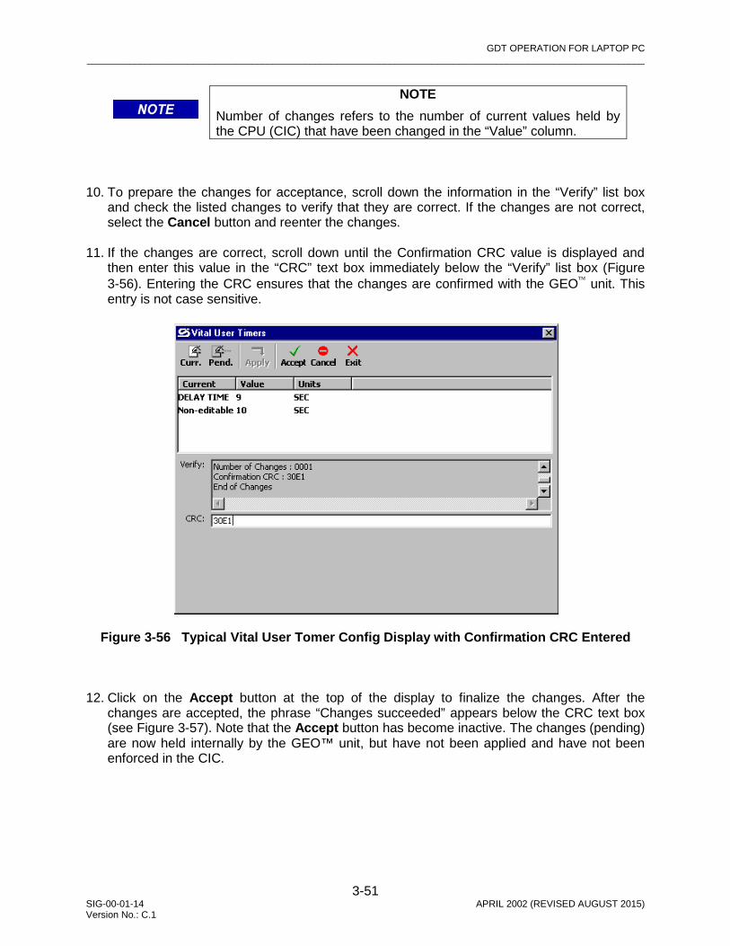
GDT OPERATION FOR LAPTOP PC _________________________________________________________________________________________________________
3-51 SIG-00-01-14 APRIL 2002 (REVISED AUGUST 2015) Version No.: C.1
NOTE
Number of changes refers to the number of current values held by the CPU (CIC) that have been changed in the “Value” column.
10. To prepare the changes for acceptance, scroll down the information in the “Verify” list box
and check the listed changes to verify that they are correct. If the changes are not correct, select the Cancel button and reenter the changes.
11. If the changes are correct, scroll down until the Confirmation CRC value is displayed and
then enter this value in the “CRC” text box immediately below the “Verify” list box (Figure 3-56). Entering the CRC ensures that the changes are confirmed with the GEO unit. This entry is not case sensitive.
Figure 3-56 Typical Vital User Tomer Config Display with Confirmation CRC Entered
12. Click on the Accept button at the top of the display to finalize the changes. After the
changes are accepted, the phrase “Changes succeeded” appears below the CRC text box (see Figure 3-57). Note that the Accept button has become inactive. The changes (pending) are now held internally by the GEO™ unit, but have not been applied and have not been enforced in the CIC.

GDT OPERATION FOR LAPTOP PC _________________________________________________________________________________________________________
3-52 SIG-00-01-14 APRIL 2002 (REVISED AUGUST 2015) Version No.: C.1
NOTE
At this point in the change process, changes have not yet been uploaded to the GEO™ CIC, and additional changes can be made. If the Cancel button is selected at any time during this first phase, the pending changes are erased.
Figure 3-57 Typical Vital User Timers Config Display with “Changes succeeded” Statement
NOTE
If “Changes failed” appears when the Accept button is selected, verify that the correct CRC was entered. If not, correct the CRC and select Accept again. If “Changes failed” is displayed again, cancel the changes and repeat the change process. If the changes fail again, reset the CPU and repeat the change process.
13. The changes that were made are now in the “pending” state, and will not become active until
a new UCN has been entered and the system rebooted.

GDT OPERATION FOR LAPTOP PC _________________________________________________________________________________________________________
3-53 SIG-00-01-14 APRIL 2002 (REVISED AUGUST 2015) Version No.: C.1
NOTE
Do not select the Cancel button unless the changes just entered on this display are to be cancelled. If the Cancel button was selected at any time during the first phase of the change process after new values were entered (effects value changes on current display only), no pending values will be displayed when the Pending button is selected and the statement “No Changes Pending” will appear in the “Verify” list box.
NOTE
Pending changes are the changes made to the current values. To view pending changes before proceeding, select the Pending button at the top of the display. The Timers that are pending are listed in the “Pending” column, and their values are displayed in the “Value” column (refer to Figure 3-58).
Figure 3-58 Typical Vital User Timers Config Display Showing Pending Timers and
Values
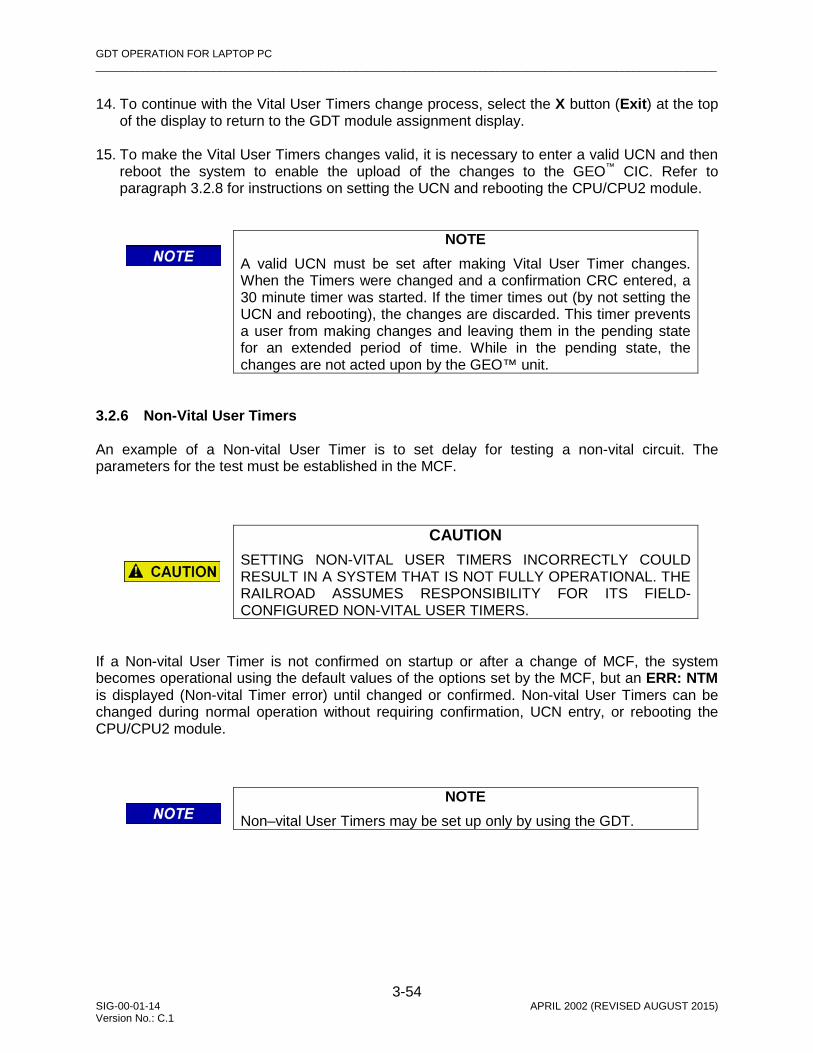
GDT OPERATION FOR LAPTOP PC _________________________________________________________________________________________________________
3-54 SIG-00-01-14 APRIL 2002 (REVISED AUGUST 2015) Version No.: C.1
14. To continue with the Vital User Timers change process, select the X button (Exit) at the top of the display to return to the GDT module assignment display.
15. To make the Vital User Timers changes valid, it is necessary to enter a valid UCN and then
reboot the system to enable the upload of the changes to the GEO™ CIC. Refer to paragraph 3.2.8 for instructions on setting the UCN and rebooting the CPU/CPU2 module.
NOTE
A valid UCN must be set after making Vital User Timer changes. When the Timers were changed and a confirmation CRC entered, a 30 minute timer was started. If the timer times out (by not setting the UCN and rebooting), the changes are discarded. This timer prevents a user from making changes and leaving them in the pending state for an extended period of time. While in the pending state, the changes are not acted upon by the GEO™ unit.
3.2.6 Non-Vital User Timers
An example of a Non-vital User Timer is to set delay for testing a non-vital circuit. The parameters for the test must be established in the MCF.
CAUTION SETTING NON-VITAL USER TIMERS INCORRECTLY COULD RESULT IN A SYSTEM THAT IS NOT FULLY OPERATIONAL. THE RAILROAD ASSUMES RESPONSIBILITY FOR ITS FIELD-CONFIGURED NON-VITAL USER TIMERS.
If a Non-vital User Timer is not confirmed on startup or after a change of MCF, the system becomes operational using the default values of the options set by the MCF, but an ERR: NTM is displayed (Non-vital Timer error) until changed or confirmed. Non-vital User Timers can be changed during normal operation without requiring confirmation, UCN entry, or rebooting the CPU/CPU2 module.
NOTE
Non–vital User Timers may be set up only by using the GDT.

GDT OPERATION FOR LAPTOP PC _________________________________________________________________________________________________________
3-55 SIG-00-01-14 APRIL 2002 (REVISED AUGUST 2015) Version No.: C.1
The GDT procedure for setting the Non-vital User Timers is as follows: 1. Bring up the Non-vital User Timers screen (Configure menu/Non-vital User Timers). Figure
3-59 presents a typical Non-vital User Timers screen. This display enables the user to initiate a change of the Non-vital User Timers defined in the MCF and stored in the CIC.
Figure 3-59 Typical Non-Vital User Timers Config Display with Current Values
2. The current settings of the parameters are listed under the Value column (click on the
Current Options button at the top of the screen to refresh the current options).
NOTE
The current values are what the GEO™ unit is currently operating with and are stored in the CIC.
3. To change a value, select that field in the “Value” column. A
drop-down option box appears in place of the selected value (see drop-down option box at right). Select the down arrow () button in the option box to display the list of available values (current value is highlighted). For the example above, the available values are True, False, Off and On. The available values depend on the type of Non-vital User Timers selected. Select the desired value from the drop-down list. The drop-down list closes and the newly selected value replaces the former value in the “Value” column.

GDT OPERATION FOR LAPTOP PC _________________________________________________________________________________________________________
3-56 SIG-00-01-14 APRIL 2002 (REVISED AUGUST 2015) Version No.: C.1
NOTE
When the change field requires a numeric value, spin buttons automatically appear to allow the values to be incremented/decremented by valid amounts (hold down to change continuously).
4. After all value changes are completed using the process just described, select the Apply button at the top of the display (refer to Figure 3-60). The GDT processes the changes and uploads them to the GEO™ CIC where they become effective immediately. There are no pending values for Non-Vital User Timers.
Figure 3-60 Typical Non-Vital User Timers Config Display after Changes
3.2.7 Set SIN The current SIN may be viewed from the header of the main GDT screen during a normal session using the DT port of the CPU/CPU2 module, from the SIN screen of the GDT, or from the Bootstrap Text Terminal screen during a reboot. The current SIN may be changed only by using the SIN screen of the GDT.
NOTE
There are two phases to the process of changing the SIN; 1) entering the change, and 2) providing a valid UCN to enable uploading the change to the CIC and rebooting the GEO™ unit to allow the changes to take effect.

GDT OPERATION FOR LAPTOP PC _________________________________________________________________________________________________________
3-57 SIG-00-01-14 APRIL 2002 (REVISED AUGUST 2015) Version No.: C.1
The SIN is protected by the UCN (Unique Check Number), therefore, if the SIN is changed, the Installer/Maintainer must enter the applicable UCN for these options and then reboot the CPU/CPU2 module. If the UCN is incorrect, the GEO system boots up unconfigured. The GDT procedure for setting the SIN is as follows:
1. Using the GDT, bring up the SIN screen (Configure menu/Set SIN). The SIN screen (Figure
3-61) is displayed presenting the “Current SIN” in a text box.
Figure 3-61 Typical Set SIN Display with Current SIN
NOTE
If the SIN does not appear in the “Current SIN” text box on the SIN screen, click on the Current (Curr.) button to display the SIN.
2. The current SIN is also displayed in a “Verify” list box immediately below the “Current SIN”
text box (refer to Figure 3-61). The current SIN in the text box must match the SIN in the “Verify” list box.
NOTE
An ATCS address (SIN) is not used in all applications, however, a SIN is generated for the MCF in order to be included with the UCN calculation. This SIN may be changed, but requires a change of UCN.
GDT OPERATION FOR LAPTOP PC _________________________________________________________________________________________________________
3-58 SIG-00-01-14 APRIL 2002 (REVISED AUGUST 2015) Version No.: C.1
NOTE
A SIN of all zeros is invalid (a number must be assigned), and in such a case the “Verify” list box indicates that the SIN is “illegal”. Assign a valid SIN.
WARNING CHANGING THE SIN REQUIRES REBOOTING THE GEO™ SYSTEM. BEFORE CHANGING THE SIN, ENSURE THAT ADEQUATE PRECAUTIONS ARE TAKEN TO PROTECT PERSONNEL, TRAINS AND OTHER VEHICLES IN THE AREA UNTIL PROPER SYSTEM OPERATION HAS BEEN VERIFIED.
3. To change the SIN, modify the number in the “Current SIN” text box as required (last digit
changed to 1 in this example), and select the Apply button at the top of the display. The new SIN is displayed in the “Current SIN” text box.
WARNING TO ENSURE THAT NO POTENTIAL SAFETY CONFLICTS CAN OCCUR WITH OTHER EQUIP-MENT, VERIFY THAT THE NEW SIN IS UNIQUE TO THE GEO™ DEVICE BEING CONFIGURED.
WARNING A SYSTEM REBOOT COULD OCCUR AT ANY TIME WHILE PERFORMING CHANGES TO THE SIN. PAY CLOSE ATTEN¬TION TO MODULE INDICATORS AND THE FOUR-CHARACTER DISPLAY ON THE CPU/CPU2 MODULE TO MONITOR SYSTEM STATUS. IF A REBOOT OCCURS BEFORE THE CHANGE PROCESS IS COMPLETE, THE ORIGINAL SIN WILL REMAIN IN EFFECT UNLESS CHANGES WERE UPLOADED TO THE CIC.
NOTE
If a reboot occurs during the burning of the CIC, Site Identification Number changes could be corrupted. This will be detected by the UCN check performed by the GEO™ unit during reboot.

GDT OPERATION FOR LAPTOP PC _________________________________________________________________________________________________________
3-59 SIG-00-01-14 APRIL 2002 (REVISED AUGUST 2015) Version No.: C.1
4. The Apply button is disabled as the GDT sends the changes to the GEO™ unit which processes the changes and then returns data that is displayed in the SIN window “Verify” list box (see Figure 3-62).
Figure 3-62 Typical Set SIN Display with New SIN
WARNING COMPARE THE SIN IN THE “SIN” TEXT BOX WITH THE SIN IN THE “VERIFY” LIST BOX; THEY MUST MATCH. ALSO VERIFY THAT THE “NUMBER OF CHANGES” INDICATES 1.
5. To prepare the change for acceptance, scroll down the information in the “Verify” list box until the Confirmation CRC value is displayed. Using the keyboard, enter this value in the “CRC” text box immediately below the “Verify” list box (see Figure 3-63). Entering the CRC ensures that the changes are sent to the GEO™ unit. This entry is not case sensitive.

GDT OPERATION FOR LAPTOP PC _________________________________________________________________________________________________________
3-60 SIG-00-01-14 APRIL 2002 (REVISED AUGUST 2015) Version No.: C.1
Figure 3-63 Typical Set SIN Display with Confirmation CRC Entered 6. Select the Accept button at the top of the display to finalize the changes. After the changes
are accepted, the Accept button is disabled and the phrase “Changes succeeded” appears below the CRC text box (see Figure 3-64).
Figure 3-64 Typical Set SIN Display with “Changes succeeded” Statement
7. The changes are now held internally by the GEO™ unit, but have not been applied and have
not been burned in the CIC.

GDT OPERATION FOR LAPTOP PC _________________________________________________________________________________________________________
3-61 SIG-00-01-14 APRIL 2002 (REVISED AUGUST 2015) Version No.: C.1
NOTE
At this point in the change process, changes have not yet been uploaded to the GEO™ CIC. Additional changes can be made at this time. If the Cancel button is selected at any time during this first phase, the pending changes are erased.
NOTE
If “Changes failed” appears when the Accept button is selected, verify that the correct CRC was entered. If not, correct the CRC and select Accept again. If “Changes failed” is displayed again, cancel the changes and repeat the change process. If the changes fail again, reset the CPU and repeat the change process.
8. To make the SIN change valid, it is necessary to enter a valid UCN and then reboot the
system to enable the upload of the changes to the GEO™ CIC. Refer to paragraph 3.2.8 for instructions on setting the UCN and rebooting the system.
WARNING ALWAYS VERIFY SITE IDENTIFICATION NUMBER CHANGES AFTER COMPLETING THE CHANGE PROCESS.
NOTE
The vital configuration protocol provides a 30 minute timer that starts when parameters are changed or a confirmation CRC is entered. If the timer times out (by not setting the UCN and rebooting), the changes are discarded. This timer prevents a user from making changes and leaving them in the pending state for an extended period of time. While in the pending state, the changes are not acted upon by the GEO™ unit.

GDT OPERATION FOR LAPTOP PC _________________________________________________________________________________________________________
3-62 SIG-00-01-14 APRIL 2002 (REVISED AUGUST 2015) Version No.: C.1
3.2.8 Set UCN The UCN (Unique Check Number) is a configuration validation number calculated from the contents of an approved MCF, MEF and field-configurable CIC options. This number must be entered following any changes to SIN, Vital User Options, or Configuration Parameters (refer to Section IV for information on vital configuration and UCN configuration protocols). Once the UCN is successfully entered, the system must be rebooted for the changes to take effect.
NOTE
It is recommended that the MCF CRC, SIN and vital user options are set before the UCN is set. Once the UCN is set, additional changes cannot be made to parameters protected by the UCN without requiring another change of UCN.
NOTE
The GDT vital configuration protocol provides a 30 minute watchdog timer that starts when parameters are changed or a confirmation CRC is entered. If the watchdog times out (by not setting the UCN and rebooting), the changes are discarded. This timer prevents a user from making changes and leaving them in the pending state for an extended period of time. While in the pending state, the changes are not acted upon by the GEO™ unit.
The process for setting the UCN is different for the Installers version and Maintainers version of the GDT. Only authorized railroad personnel are issued the Installers version. The Installers version allows the user to request that the GEO™ unit calculate the new UCN for the new SIN or Vital User Options to be stored in the CIC. The Maintainer must be issued the new UCN along with detailed change instructions by railroad supervisory personnel.
WARNING CARE SHOULD BE EXERCISED IN THE DISTRI¬BUTION AND USE OF THE INSTALLER VERSION OF THE GDT. BECAUSE THE INSTALLER VERSION CAN CALCULATE THE UCN FOR ANY CHANGES IN VITAL OPTIONS, THE POTENTIAL EXISTS FOR IMPROPER OR UNSAFE VITAL OPTION INPUT TO THE SYSTEM.

GDT OPERATION FOR LAPTOP PC _________________________________________________________________________________________________________
3-63 SIG-00-01-14 APRIL 2002 (REVISED AUGUST 2015) Version No.: C.1
To initiate the process of uploading changes, select “Set UCN” from the Configure menu. A display similar to the one shown in Figure 3-65 appears on the screen.
Figure 3-65 Set UCN Display (Installers Version)
NOTE
Only the Installers version has an active Get UCN button on the UCN display. With the Maintainers version of the GDT, the Get UCN button is disabled on the UCN display.
The Maintainers version and the Installers version of the GDT differ in the way the UCN is obtained and set. The Maintainers version of the GDT does not allow the user to request the GEO system to calculate a new UCN for any changes in vital options. The Maintainer must request the new UCN from the proper railroad supervisory personnel. Refer to Figure 3-69 for a typical Set UCN display for the Maintainers version of the GDT.
NOTE
The Maintainers version of the GDT software is incapable of calculating the UCN for any changes in vital options. Only the Installers version of the GDT can calculate the UCN for any changes in vital options.

GDT OPERATION FOR LAPTOP PC _________________________________________________________________________________________________________
3-64 SIG-00-01-14 APRIL 2002 (REVISED AUGUST 2015) Version No.: C.1
3.2.8.1 UCN for Installers Version Only
WARNING THE GDT INSTALLERS VERSION CAN CALCULATE THE UCN FOR ANY CHANGES IN VITAL OPTIONS. VERIFY THAT ALL VITAL OPTION CHANGES ARE PER RAILROAD SPECIFICATION BEFORE GENER¬ATING THE UCN.
1. For obtaining and entering the UCN for the installers version, click on the Get UCN button at
the top of the display. A new UCN is generated by the GEO™ wayside unit and displayed in the “New UCN” text box (see Figure 3-66).
Figure 3-66 Set UCN Display (Installers Version) with Generated UCN
NOTE
The UCN displayed when the Get UCN button is clicked on is calculated when the request is made. To view the UCN currently stored in the CIC, select the “CPU Version” option from the View menu (paragraph 3.5.1).
2. Enter this new UCN in the “Set UCN to” text box (this entry is not case sensitive). Verify that the entered UCN matches the generated UCN.

GDT OPERATION FOR LAPTOP PC _________________________________________________________________________________________________________
3-65 SIG-00-01-14 APRIL 2002 (REVISED AUGUST 2015) Version No.: C.1
3. Simultaneously press and release the Select and Navigate push buttons on the GEO™ CPU module, then click on the Set UCN button at the top of the display. The statement “Changes saved successfully” appears on the GDT display (Figure 3-67).
Figure 3-67 Set UCN Display (Installers Version) “Changes saved successfully”
NOTE
When the Select and Navigate push buttons are pressed, a 1-minute timer provided by the vital configuration protocol is started. The Set UCN button must be clicked on before that timer times out. If the timer times out, press and release the Select and Navigate push buttons again before clicking on the Set UCN button. Otherwise, the user is prompted by the Set UCN message shown below.
NOTE
If the Set UCN button is clicked on, but the Select and Navigate push buttons on the GEO™ unit were not pressed as directed (see Figure 3-66), the Set UCN message shown at right is displayed. Click on the OK button in the message box and then repeat the button sequence.

GDT OPERATION FOR LAPTOP PC _________________________________________________________________________________________________________
3-66 SIG-00-01-14 APRIL 2002 (REVISED AUGUST 2015) Version No.: C.1
NOTE
If an incorrect UCN is entered, The statement “Error: UCN incorrect.” appears above the “Changes saved successfully” statement as shown in Figure 3-68. If this is the result of a mistake, enter the correct UCN, simultaneously press and release the Select and Navigate push buttons and, within 1 minute, click on the Set UCN button.
Figure 3-68 Set UCN Display (Installers Version) “Error UCN Incorrect”
NOTE
An incorrect UCN can be entered deliberately to disable the GEO™ unit.
4. To upload the changes to the GEO™ CIC, click on the Reboot button at the top of the GDT
display. Observe the four-character display on the CPU module to verify that a reboot sequence has been initiated (reads “SDWN” followed by “BOOT”).
NOTE
The GDT vital configuration protocol provides a 5 minute timer that starts when the Set UCN button is selected. If the Reboot button is not clicked on before the timeout period ends, the system automatically reboots.

GDT OPERATION FOR LAPTOP PC _________________________________________________________________________________________________________
3-67 SIG-00-01-14 APRIL 2002 (REVISED AUGUST 2015) Version No.: C.1
WARNING
WHEN THE REBOOT IS COMPLETE, RESTART THE GDT IF NECESSARY, AND VERIFY THAT THE CURRENT VALUES OF THE ITEMS THAT WERE CHANGED AGREE WITH THE CHANGES MADE AND UPLOADED TO THE CIC.
WARNING FOLLOWING A SUCCESSFUL CHANGE OF UCN, VITAL FUNCTIONS MUST BE TESTED AND VERIFIED PER RAILROAD POLICY.
3.2.8.2 UCN for Maintainers Version Only 1. For entering the UCN for the maintainers version, enter the new UCN provided with the
change instructions in the “Set UCN to” text box (this entry is not case sensitive). Verify that the entered UCN matches the UCN provided.
2. Simultaneously press and release the Select and Navigate push buttons on the GEO™ CPU
module, then click on the Set UCN button at the top of the display. The statement “Changes saved successfully” appears on the GDT display (Figure 3-69).
Figure 3-69 Set UCN Display (Maintainers Version) “Changes saved successfully”

GDT OPERATION FOR LAPTOP PC _________________________________________________________________________________________________________
3-68 SIG-00-01-14 APRIL 2002 (REVISED AUGUST 2015) Version No.: C.1
NOTE
When the Select and Navigate push buttons are pressed, a 1-minute timer provided by the vital configuration protocol is started. The Set UCN button must be clicked on before that timer times out. If the timer times out, perform the press and release sequence on the Select and Navigate push buttons again before selecting the Set UCN button. Otherwise, the Set UCN prompt shown below will be displayed.
NOTE
If the Set UCN button is clicked on, but the Select and Navigate push buttons on the GEO™ unit were not pressed as directed (see Figure 3-69), the Set UCN message shown at right is displayed. Click on the OK button in the message box and then repeat the button sequence.
NOTE
If an incorrect UCN is entered, The statement “Error: UCN incorrect.” appears above the “Changes saved successfully” statement as shown in Figure 3-70. If this is the result of a mistake, enter the correct UCN, simultaneously press the Select and Navigate push buttons and then release them and, within 1 minute, click on the Set UCN button.
Figure 3-70 Set UCN Display (Maintainers Version) “Error: UCN incorrect”

GDT OPERATION FOR LAPTOP PC _________________________________________________________________________________________________________
3-69 SIG-00-01-14 APRIL 2002 (REVISED AUGUST 2015) Version No.: C.1
NOTE
An incorrect UCN can be entered deliberately to disable the GEO™ unit.
3. To upload the changes to the GEO™ CIC, select the Reboot button at the top of the GDT
display. Observe the four-character display on the CPU module to verify that a reboot sequence has been initiated (reads “SDWN” followed by “BOOT”).
NOTE
The vital configuration protocol provides a 5 minute timer that starts when the Set UCN button is clicked on. If the Reboot button is not clicked on before the timeout period ends, the system is automatically reboots.
WARNING WHEN THE REBOOT IS COMPLETE, RESTART THE GDT IF NECESSARY, AND VERIFY THAT THE CURRENT VALUES OF THE ITEMS THAT WERE CHANGED AGREE WITH THE CHANGES MADE AND UPLOADED TO THE CIC.
WARNING FOLLOWING A SUCCESSFUL CHANGE OF VITAL USER OPTIONS, VITAL OPTION CONFIGU-RATIONS MUST BE TESTED AND VERIFIED PER RAILROAD POLICY.
3.2.9 Set Time The Set Time function is used to set the GEO™ real time clock in the CPU module. The output from this clock is provided to the I/O modules for event time stamps. The date and time can be set at any time, by using either the GDT or the Maintainers Interface. The GDT procedure for setting date and time is as follows: 1. From the GDT main screen, select Set Time from the Configure menu. 2. The Time window is displayed (Figure 3-71), with the currently set date and time displayed.

GDT OPERATION FOR LAPTOP PC _________________________________________________________________________________________________________
3-70 SIG-00-01-14 APRIL 2002 (REVISED AUGUST 2015) Version No.: C.1
Figure 3-71 Time Window 3. When setting time, select “Refresh” to refresh the display with the current CPU time.
NOTE
To automatically adjust the GEO™ CPU time to the PC system time, select System.
4. To change any portion of the date/time, highlight the field to be changed and type in the new
value, or alternatively, right-click on the highlighted field to bring up a shortcut menu containing the “Cut”, “Copy”, “Paste”, “Delete”, and “Select All” functions.
NOTE
To make it easier to synchronize the time, enter a time that is a few seconds later than the current time and wait for the actual time to arrive before selecting Set
5. When the correct date and time has been entered, or when the set time arrives, select the
Set button.
NOTE
GEO™ system time is in 24-hour format.
6. Select the Exit button to close the Time window and return to the GDT main screen. 3.2.10 Delete MCF The “Delete MCF” function is provided to invalidate the MCF, or as a quick means of disabling the GEO unit, and can be done either remotely or locally.

GDT OPERATION FOR LAPTOP PC _________________________________________________________________________________________________________
3-71 SIG-00-01-14 APRIL 2002 (REVISED AUGUST 2015) Version No.: C.1
NOTE
Deleting the MCF makes the GEO™ wayside unit inoperative in a fail-safe mode.
NOTE
Deleting the MCF makes the GEO™ wayside unit inoperative in a fail-safe mode. Deleting the MCF can be done remotely, however, once deleted, the MCF must be reinstalled locally.
The procedure for deleting the MCF is as follows: 1. From the Configure menu of the GDT, select “Delete MCF”. 2. The confirmation prompt shown below is displayed to allow this command to be executed or
cancelled.
3. Click on Yes to delete the MCF or click on No to cancel the function. 4. If Yes is clicked on, the GEO unit reboots unconfigured, causing the unit to be disabled in a
safe mode.
NOTE
Error messages on the 4-character display of the CPU/CPU2 module will include: ERR: MCF* CRC* MCI* SIN* UCN* NOP* VOP*.
3.3 SETUP MENU
The Setup menu contains the functions listed below and described in the paragraphs that follow.
• Communication • Destination Address

GDT OPERATION FOR LAPTOP PC _________________________________________________________________________________________________________
3-72 SIG-00-01-14 APRIL 2002 (REVISED AUGUST 2015) Version No.: C.1
3.3.1 Communication Selecting the “Communication” option from the Setup menu produces the Serial Port Settings display shown in Figure 3-72. This display is used to select the serial communications port and the baud rate settings for the PC. The default settings are COM1 and 56000 baud.
Figure 3-72 Serial Port Settings Display
NOTE
The baud rate setting is dependent on the capabilities of the PC. Click on the OK button to close the display and save the new settings. Click on the Cancel button to close the display without saving new settings.
NOTE
When attempting to establish communications between the GDT and the GEO™ unit, if an error message is displayed indicating that the incorrect serial port is selected, check the Windows® task list for multiple copies of the GDT Diagnostic Terminal application (see Figure 3-73). Multiple or phantom copies of the GDT Diagnostic Terminal program can remain if communication is inadvertently lost between the GDT and the GEO™ unit.

GDT OPERATION FOR LAPTOP PC _________________________________________________________________________________________________________
3-73 SIG-00-01-14 APRIL 2002 (REVISED AUGUST 2015) Version No.: C.1
NOTE
To remove multiple copies of the GDT (see Figure 3-73), press the Ctrl, Alt and Delete keys on the keyboard once to display the task list, then select and end each occurrence of the GDT Diagnostic Terminal application. Close the task list and restart the GDT application.
Figure 3-73 Windows® Task List with Multiple GDT Diagnostic Terminal Occurrences 3.3.2 Destination Address Selecting “Destination Address” from the Setup menu produces the menu shown in Figure 3-74. This menu contains two options as follows: • local • remote
Figure 3-74 Destination Address Menu Select the “local” option (a checkmark is placed next to the “local” Destination Address in the Setup menu) if the GDT is to monitor only the GEO™ unit it is connected to via the serial cable. The display of Figure 3-75 appears as the GDT reestablishes the connection with that GEO™ unit.
Multiple Copies

GDT OPERATION FOR LAPTOP PC _________________________________________________________________________________________________________
3-74 SIG-00-01-14 APRIL 2002 (REVISED AUGUST 2015) Version No.: C.1
Figure 3-75 GDT Data Download Display (Following Local Destination Address
Selection) Select the “remote” option from the Destination Address menu if the GDT is to monitor a GEO™ unit on a LAN other than the unit it is connected to via the serial cable. The display shown in Figure 3-76 appears.
Figure 3-76 Remote Destination Address Display
NOTE
The “Source Address” and “Destination Address” fields in the ATCS Destination Address display are inactive until either “Remote’ or “Full Remote” is selected.
The ATCS Destination Address display offers two options for connecting remotely, as follows: • Remote Use to communicate with a remote GEO™ unit (destination address)
when the DT is connected to a GEO™ unit (source address not required) • Full Remote Use to communicate with a remote GEO™ unit (destination address)
when the DT is connected to a GEO™ LAN through another means (source address)

GDT OPERATION FOR LAPTOP PC _________________________________________________________________________________________________________
3-75 SIG-00-01-14 APRIL 2002 (REVISED AUGUST 2015) Version No.: C.1
One of the two options above must be selected to communicate remotely. A checkmark is then placed next to the “remote” Destination Address in the Setup menu. For the “Remote” option, enter the ATCS destination address of the remote unit and then select the OK button. The GDT connects to the remote unit as previously described for the local unit.
NOTE
Full Remote is not currently implemented.
For the “Full Remote” option, the ATCS source address as well as the ATCS destination address of the remote unit must be identified. The source address field provides spin buttons to select type “7” (ATCS) addressing, or type “2” addressing when required.
WARNING EXERCISE EXTREME CAUTION WHEN REMOTELY CHANGING VITAL USER OPTIONS OR SAFETY RELATED PARAMETERS. AUTHORIZED RAIL¬ROAD PERSONNEL MUST BE PRESENT AT THE REMOTE LOCATION. CHANGING VITAL USER OPTIONS REQUIRES REBOOTING THE GEO™ SYSTEM AND AFFECTS VITAL SYSTEM LOGIC OPERATIONS. ENSURE THAT ADEQUATE PRECAUTIONS ARE TAKEN TO PROTECT PERSONNEL, TRAINS AND OTHER VEHICLES IN THE AREA UNTIL PROPER SYSTEM OPERATION HAS BEEN VERIFIED.
WARNING FOLLOWING A SUCCESSFUL CHANGE OF VITAL USER OPTIONS OR SAFETY RELATED PARAME¬TERS, VITAL OPTION CONFIGU-RATIONS MUST BE TESTED AND VERIFIED PER RAILROAD POLICY.
To cancel the remote address selection before the OK button on the Remote Destination Address Entry display has been clicked on, select the Cancel button on the ATCS Destination Address display (Figure 3-76). The “remote” option will remain selected () on the Destination Address menu but the GDT will remain in communication with the local unit.

GDT OPERATION FOR LAPTOP PC _________________________________________________________________________________________________________
3-76 SIG-00-01-14 APRIL 2002 (REVISED AUGUST 2015) Version No.: C.1
3.4 TOOLS MENU
The Tools menu contains one entry: “Sniffer”. Select “Sniffer” to display the Sniffer screen depicted in Figure 3-77.
NOTE
The Sniffer is provided as a diagnostic tool primarily for use by Siemens Engineering personnel.
The Sniffer monitors ATCS message activity between the GEO™ unit CPU and the GDT and displays the message bytes for evaluation. This is a dynamic display. As new message traffic occurs, it is added to the bottom of the display and the message list scrolls up screen. Select the Stop button to freeze the display so that currently displayed messages may be examined. The button label changes to Continue. Select the button again to continue monitoring messages as they occur.
Figure 3-77 Typical Sniffer Display
Select the Clear button to remove all currently displayed messages from the screen. New messages will appear on the display as they are sent or received. Select the Close button to exit this display and return to the module assignment display.

GDT OPERATION FOR LAPTOP PC _________________________________________________________________________________________________________
3-77 SIG-00-01-14 APRIL 2002 (REVISED AUGUST 2015) Version No.: C.1
3.5 VIEW MENU
The View menu contains the four functions listed below and described in the following paragraphs.
• CPU Version
• Statistics
• Logic States
• Refresh
3.5.1 CPU Version Selecting “CPU Version” from the View menu produces a display similar to the one in Figure 3-78.
Figure 3-78 Typical GDT CPU Version Display The following information is provided by this display: • Module Type - number assigned to module in Siemens Peripheral Card Interface
Specification (see Table 3-3). • MEF Version - the current GEO™ module executable file (MEF). • MEF MCF CI - the MEF to Module Configuration File (MCF) compatibility index (CI). This
field is intended for factory use only. • MEF HW CI - the MEF to hardware (HW) compatibility index. This field is intended for
factory use only. • UCN - the current unique configuration number (UCN). • MEF CRC – the current MEF cycle redundancy check (CRC) number. • In/Out Service Check Number – the service status number generated by the GEO™ unit. • MCF Name – the file name of the current MCF. • Location – the group location of the current MCF.

GDT OPERATION FOR LAPTOP PC _________________________________________________________________________________________________________
3-78 SIG-00-01-14 APRIL 2002 (REVISED AUGUST 2015) Version No.: C.1
Select the Refresh button to update the information fields on the display. Select the Exit button to return to the module assignment display.
Table 3-3 Module Type Indentification
Type ID Module Description
01 GEO C oded T rack module (T R K ), compatible with E lectro C ode
02 GEO Searchlight module (SLS) – supports 2 mechanisms, and has 2 auxiliary VPIs and 1 auxiliary VRO
03 GEO Colorlight module (CLS) – supports 6 VLOs, 2 auxiliary VPIs and 1 auxiliary VRO
04 GEO Coded Line module (LIN), used to carry track codes on wayside cable, compatible with Electro Code
05 GEO Vital Parallel Input module (VPI) – supports 8 VPIs and 2 NVAI
06 GEO Vital Relay Output module (VRO) – supports 6 VROs
07 GEO CPU module for use primarily in intermediate signals applications, no Echelon LAN and no serial communication capability. Supports 8 I/O Cards.
08 GEO General purpose I/O module (RIO), supports 4 VPIs, 4 VROs
09 GEO CPU2 module vital logic processor (VLP) - supports interface to CP_PROC and 8 I/O modules
10 GEO CPU2 module non-vital/communication processor (CP) - supports interface to VLP2_PROC, and Echelon port and 2 serial ports (RS-232,422, 485).
11 Reserved for future use
12 Reserved for future use
13 Reserved for future use
14 Reserved for future use
3.5.2 Logic States The “Logic State” window (refer to Figure 3-80) is a diagnostic tool that provides viewing capability for up to 600 selected logic states from a maximum of 2046 supported logic states. Selecting “Logic States” from the View menu produces a display similar to the one shown in Figure 3-79.
NOTE
The Logic States function is provided as a diagnostic tool primarily for use by Siemens Engineering personnel.

GDT OPERATION FOR LAPTOP PC _________________________________________________________________________________________________________
3-79 SIG-00-01-14 APRIL 2002 (REVISED AUGUST 2015) Version No.: C.1
Figure 3-79 Typical GDT Logic States Entry Display
Figure 3-80 Typical GDT
Logic States Listing Display
The Logic States menu selection allows the current logic state data for these functions to be retrieved from the GEO™ CPU. The logic states entry display shown in Figure 3-79 allows the user to enter a range of logic states to be examined.
NOTE
The value entered in the “First Logic State” text box must be smaller than the value entered in the “Last Logic State” text box
NOTE
The GDT can download a maximum of 600 logic states per request.
After the range values are entered, select the OK button. The GDT retrieves the data and displays it as shown in Figure 3-80. This is a snap shot of the current logic states. Displayed logic state values are 1 and 0 where:
1 = true 0 = false
Select the Refresh button to update the logic state “Value” fields on the display. A scroll bar is provided on the right side of the display to enable viewing the entire list.

GDT OPERATION FOR LAPTOP PC _________________________________________________________________________________________________________
3-80 SIG-00-01-14 APRIL 2002 (REVISED AUGUST 2015) Version No.: C.1
To return to the logic states entry display (Figure 3-79) to enter new range values, use the Select button. Select the Exit button to return to the opening display. 3.5.3 DT Staistics Selecting “Statistics” from the View menu displays the “DT Statistics” window (similar to the one shown in Figure 3-81).
Figure 3-81 Typical GDT Statistics Display This window provides a snapshot of communications statistics pertaining to the DT port on the CPU/CPU2 module. The data in this display can be refreshed and/or cleared. Some types of data that can be displayed include but are not limited to the following: • CPU (VLP) reboots • Bad SIO packets • Valid / Invalid DT packets • I/O card Bad CRC’s • SIO Tx and Rx packets • I/O card reboots • I/O card lost sessions
To provide access to a pop-up menu (Figure 3-82) that permits the user to select the type of statistics to be displayed, click on the Type button ( ) in the GDT Statistics display.

GDT OPERATION FOR LAPTOP PC _________________________________________________________________________________________________________
3-81 SIG-00-01-14 APRIL 2002 (REVISED AUGUST 2015) Version No.: C.1
Figure 3-82 GDT Statistics Type Display The GEO™ equipment configuration determines to some extent the type of statistics that can be viewed. For example, the Vital ATCS, Nonvital ATCS and LAN statistics can only be viewed when the GDT is connected to a CPU2 module. The VLP Statistics apply only to the CPU module and Card Statistics apply only to I/O cards. If a type is selected that is not supported by the GEO™ hardware configuration, the following message appears in place of the statistics: “Statistic Not Supported”. Select the Refresh button to update the statistic value fields currently on the display. Select the Clear button to delete the record of the displayed statistic currently stored by the GEO™ system. All values will return to zero. Select the Exit button to return to the opening display. 3.5.4 Refresh Select “Refresh” to update the module assignment display with current module status.
3.6 HELP MENU
The Help menu contains one entry: “About GEO Diagnostic Terminal”. Select “About GEO Diagnostic Terminal” and a display similar to Figure 3-83 appears.
Figure 3-83 About GEO™ Diagnostic Terminal

GDT OPERATION FOR LAPTOP PC _________________________________________________________________________________________________________
3-82 SIG-00-01-14 APRIL 2002 (REVISED AUGUST 2015) Version No.: C.1
This display identifies the GDT software version, whether the application is “Installer” or “Maintainer”, and the software part number. Select the OK button to close the “About GEO Diagnostic Terminal” display and return to the module assignment display.
3.7 INDIVIDUAL MODULE SETUP
The default configuration is specified in the MCF, which was initially created by using the GCS. In order to use the same MCF at multiple locations, some of the configuration items in the MCF may be changed in the field. Of the field-changeable configuration items, some are changed without requiring a new UCN, and others require a UCN change (refer to Figure 3-84).
Figure 3-84 Making Configuration Changes Refer to Figure 3-85 for a flow diagram of setup procedures, and refer to the paragraphs indicated in the figure for descriptions of those procedures.
NOTES [1] A parameter change does not affect the UCN. [2] A parameter change requires a new UCN. [3] Field-changeable if programmed in the MCF. [4] Refer to Section IV for a description of the Vital Configuration Protocol.
Module Parameter
MCF
Operating Parameters [1]
(refer to table 3-4)
Not Field-Changeable
Field-Changeable
Configuration Parameters [2] (not currently implemented)
Not Field-Changeable
Field-Changeable
User Options [3]
Vital [2] Non-Vital [1]
User Timers [3]
Vital [2] Non-Vital [1]
User I/O [3]
Vital [1] Non-Vital [1]

GDT OPERATION FOR LAPTOP PC _________________________________________________________________________________________________________
3-83 SIG-00-01-14 APRIL 2002 (REVISED AUGUST 2015) Version No.: C.1
Figure 3-85 Setup Flow Diagram
Load new MCF (paragraph 3.1.4.2)
MCF* displayed
?
Yes
No
Start
Check Operating Parameters for all
modules
Set MCF CRC (paragraph 3.1.4.3)
Load new MEF (paragraph 3.1.4.1)
Load MEF ?
Yes
No
Change Non-vital User I/O, if required
(paragraph 3.2.4)
No
Ye
Confirm or change default Module Operating
Parameters (paragraph 3.7.1.2)
NCx* displayed
?
Check error messages
CRC* displayed
?
No
Yes
No
Yes Confirm or change default Non-vital User Options
(paragraph 3.2.2)
NOP* displayed
?
No
Yes NTM* displayed
?
Confirm or change default Non-vital User Timers
(paragraph 3.2.6)
Check non-vital user setup
Setup complete
Wait for bootup (paragraph 3.2.8)
Is only the
MCF scrolling?
Yes No
Change Vital User I/O, if required
(paragraph 3.2.3)
No
Yes Confirm or change default Vital User Timers (paragraph 3.2.5)
VTM* displayed
?
No
Yes Confirm or change default Vital User Options (paragraph 3.2.1)
VOP* displayed
?
Check vital user
setup
Set SIN (paragraph (3.2.7)
No
SIN* displayed
?
Yes
No
ADR* displayed
?
Yes
Set UCN & reboot (paragraph 3.2.8)
UCN* displayed
?
No
Yes
NOTES 1. Date and Time may be set up at any time (paragraph 3.2.9). 2. A reset may be performed at any time (paragraph 3.1.4).

GDT OPERATION FOR LAPTOP PC _________________________________________________________________________________________________________
3-84 SIG-00-01-14 APRIL 2002 (REVISED AUGUST 2015) Version No.: C.1
The module assignment display shown in Figure 3-86 is a graphic representation of the modules installed in the GEO™ wayside unit and indicates their corresponding slots in the card cage. The number of slots displayed and the module assignments will vary depending on GEO™ wayside equipment configuration. Each module is identified by a label. By right clicking on a module label, a pop-up menu appears that provides access to information relative to that module only. The functions available on this menu are described in the following paragraphs. This display also provides operational and functional status information for each of the modules including lamp status and I/O status, plus some vital and non-vital voltage and current levels. The module labels also use color to indicate operational status as follows: CPU modules: red = CPU module not configured or inoperative green = CPU module configured and fully operational I/O modules: red = I/O module missing, inoperative or unable to communicate with CPU
via serial bus green = I/O module operational and communicating with CPU via serial bus
Figure 3-86 Example of Module Assignment Display 3.7.1 Module Menu The module menu format (Figure 3-87) that appears when a module label is right-clicked, is identical for each module; only the information accessed from the menu is specific to each module. The menu contains six functions which are described in the following paragraphs.
Title bar Menu bar Module labels
Module slots

GDT OPERATION FOR LAPTOP PC _________________________________________________________________________________________________________
3-85 SIG-00-01-14 APRIL 2002 (REVISED AUGUST 2015) Version No.: C.1
Figure 3-87 Module Pop-up Menu
3.7.1.1 Configuration Parameters Selecting the “Configuration Parameters” function from the module pop-up menu provides a display similar to Figure 3-88. As indicated, there are currently no configurable parameters defined.
Figure 3-88 Typical Module Configuration Parameters Display
3.7.1.2 Operating Parameters The default module Operating Parameters are specified in the MCF. Some Operating Parameters are field-changeable and others are not. Changing default Operating Parameters does not require setting the UCN.
WARNING WHEN CHANGING ANY PORTION OF A GEO™ UNIT’S CONFIGURATION, ANY FUNCTIONS AFFECTED BY THAT CHANGE MUST BE RETESTED, AND OVERALL SYSTEM OPERATION MUST BE CONFIRMED. IF THE UCN IS AFFECTED AS A RESULT OF A CHANGE, THE ENTIRE LOCATION MUST BE THOROUGHLY RETESTED IN ACCOR¬DANCE WITH FRA REGULATIONS.

GDT OPERATION FOR LAPTOP PC _________________________________________________________________________________________________________
3-86 SIG-00-01-14 APRIL 2002 (REVISED AUGUST 2015) Version No.: C.1
When the Operating Parameters screen is brought up for slot 1 (CPU/CPU2 module), the screen displays “No operating parameters defined”.
Table 3-4 lists and describes the Operating Parameters for the different module types.
WARNING THE IMPLEMENTATION OF MODULE OPERATING PARAMETER CHANGES AND THEIR EFFECTS ON RAILROAD SAFETY ARE THE RESPONSIBILITY OF THE GDT USER.
CAUTION INCORRECT CONFIGURATION OF MODULE OPERATING PARAMETERS COULD RESULT IN A SYSTEM THAT DOES NOT OPERATE AS DESIRED. THE RAILROAD ASSUMES RESPONSIBILITY FOR ITS FIELD-CONFIGURED PARAMETER OPTIONS.
NOTE
Setup data should be recorded as changes are made. Refer to the GEO™ Hardware manual, document number SIG-00-99-11, Appendix F for setup data sheet masters.
NOTE
The CPU/CPU2 module does not currently have any module Operating Parameters or Configuration Parameters. However, it does require setup for date and time, and may require setup for Vital/Non-vital User Options, User Timers, and User I/O.
NOTE
The VRO module does not currently have any module Operating Parameters defined. When the Operating Parameters screen is brought up for a VRO module, the screen displays “No operating parameters defined”.

OPERATION ______________________________________________________________________________________________________________________________________________________
3-87 SIG-00-01-14 APRIL 2002 (REVISED AUGUST 2015) Version No.: C.1
Table 3-4 Module Operating Parameters
Module Type Property Value
(range/options) Units Description Field-Changeable?
CPU/CPU2 (n/a) (n/a) (n/a) No Operating Parameters defined for CPU/CPU2 (n/a)
Track
VCO Voltage 0 thru 4000 (by 20’s) mV Set coded track output voltage (millivolts)
(adjustable in 20mV increments) Using GDT or
Maintainers Interface Receive True/False (n/a) Enable/Disable receive Not
Field-changeable Transmit True/False Enable/Disable transmit
Code 5 Standard, Long, or Alternating (n/a)
Select Code 5 option Using GDT only
EC4 Compatibility EC4, or EC4 Plus Select EC4 Compatibility option
Non-vital Change 1 – 3 cycles Number of code cycles before changing from one non-vital code to another non-vital code
Not Field-changeable
Vital Change 1 – 3 cycles
Number of code cycles: • Before changing from one vital code
to another vital code, or • Before changing from a non-vital
code to a vital code, or • Before changing from a vital code to
a non-vital code
Shunt Drop 1 – 8 cycles Number of code cycles that a code is reported after a shunt is applied
Shunt Pick 1 – 8 cycles Number of code cycles required after a shunt is picked before a code 1 is reported
Current Limit 1000 thru 10000 (by 50’s) mA Set track output Current Limit (milliamps)
(adjustable in 50mA increments) Using GDT or
Maintainers Interface Continued on the next page

OPERATION ______________________________________________________________________________________________________________________________________________________
3-88 SIG-00-01-14 APRIL 2002 (REVISED AUGUST 2015) Version No.: C.1
Table 3-4 Continued
Module Type Property Value
(range/options) Units Description Field-Changeable?
Coded Line
Transmit Voltage 2000 thru 15000 (by 100’s) mV Set line Transmit Voltage (millivolts)
(adjustable in 100mV increments) Using GDT or
Maintainers Interface Receive True/False (n/a) Enable/Disable receive Not
Field-changeable Transmit True/False Enable/Disable transmit
Code 5 Standard, Long, or Alternating (n/a)
Select Code 5 option Using GDT only
EC4 Compatibility EC4, or EC4 Plus Select EC4 Compatibility option
Non-vital Change 1 – 3 cycles Number of code cycles before changing from one non-vital code to another non-vital code
Not Field-changeable
Vital Change 1 – 3 cycles
Number of code cycles: • Before changing from one vital code to
another vital code, or • Before changing from a non-vital code
to a vital code, or • Before changing from a vital code to a
non-vital code
Shunt Drop 1 – 8 cycles Number of code cycles that a code is reported after a shunt is applied
Shunt Pick 1 – 8 cycles Number of code cycles required after a shunt is picked before a code 1 is reported
Receive Threshold
2000 thru 15000 (by 100’s) mV
Set line Receive Threshold voltage (millivoltss) (adjustable in 100mV increments)
Using GDT or Maintainers Interface
Continued on the next page

OPERATION ______________________________________________________________________________________________________________________________________________________
3-89 SIG-00-01-14 APRIL 2002 (REVISED AUGUST 2015) Version No.: C.1
Table 3-4 Concluded
Module Type Property Value
(range/options) Units Description Field-Changeable?
Color-light
Lamp Voltage 9000 thru 13500 (by 1’s) mV Set Lamp Voltage (millivolts)
(adjustable in 1 mV increments) Using GDT or
Maintainers Interface Filament
Threshold 0 mA (reserved) Not Field-changeable Cold Filament
Test Yes (n/a) (reserved)
VPI Debounce 20 thru 200 (by 2’s) ms Set VPI Debounce time (milliseconds)
(adjustable in 2ms increments) Using GDT or
Maintainers Interface
Search-light
Lamp Voltage 9000 thru 13500 (by 1’s) mV Set Lamp Voltage (millivolts)
(adjustable in 1 mV increments) Using GDT or Maintainers Interface VPI Debounce 20 thru 200
(by 2’s) ms Set VPI Debounce time (milliseconds) (adjustable in 2ms increments)
Mech1 Response 200 thru 2000 (by 10’s) ms
Set PCO #1 input mechanism response time (milliseconds) (adjustable in 10ms increments) Using GDT only
Mech2 Response 200 thru 15000 (by 10’s) ms
Set PCO #2 input mechanism response time (milliseconds) (adjustable in 10ms increments)
Mech Feedback Yes/No (n/a) Enable Mechanism Checking
Not Field-changeable
Filament Threshold 0 mA (reserved)
Cold Filament Test Yes (n/a) (reserved)
VPI, RIO VPI Debounce 20 thru 200
(by 2’s) ms Set VPI Debounce time (milliseconds) (adjustable in 2ms increments)
Using GDT or Maintainers Interface
VRO (n/a) (n/a) (n/a) No Operating Parameters (n/a)

OPERATION ______________________________________________________________________________________________________________________________________________________
3-90 SIG-00-01-14 APRIL 2002 (REVISED AUGUST 2015) Version No.: C.1
This Page Intentionally Left Blank

OPERATION _________________________________________________________________________________________________________
3-91 SIG-00-01-14 APRIL 2002 (REVISED AUGUST 2015) Version No.: C.1
The GDT may be used to view any Operating Parameter, or to change any field-changeable Operating Parameter. In addition, certain field-changeable Operating Parameters (see Table 3-4) may be viewed/changed by using the Maintainers Interface.
Selecting the “Operating Parameters” function from the module pop-up menu provides a display similar to Figure 3-89. At the top of the display is a header identifying the slot number, the type of module and the function selected from the menu. The example in Figure 3-89 identifies the module in slot 2 as a Coded Track module.
Figure 3-89 Textual Operating Parameter Option Selection
Below the header is a row of buttons for manipulating the module parameters. And below the buttons are three columns that contain the module operating parameters (properties) with corresponding values and units. Only the properties with the white background can be changed. To view the current values of the listed properties, select the Current button at the top of the display. The current values for the listed properties appear in the “Value” column opposite the entries in the “Property” column. Values can be either textual or numerical in nature. To change a textual value, select that value in the “Value” column. A drop-down list control box appears containing the selected value (see Figure 3-89).
NOTE
The system must be configured in order to use Operating Parameter setup procedures.
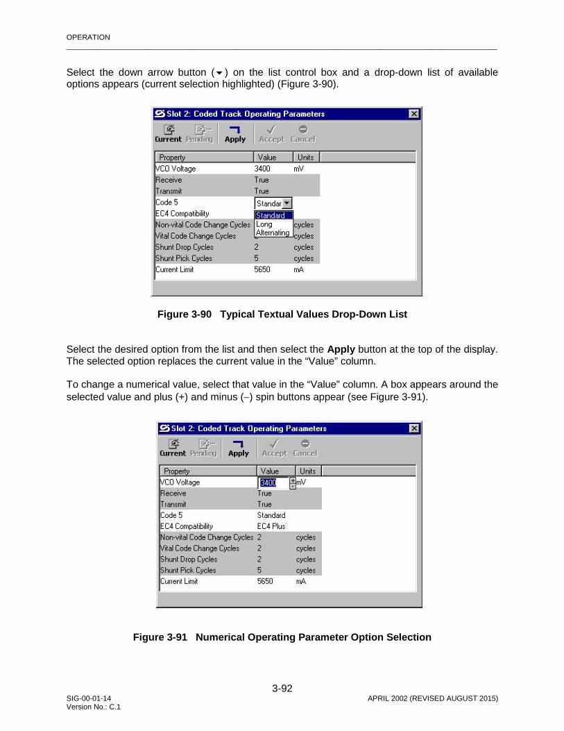
OPERATION _________________________________________________________________________________________________________
3-92 SIG-00-01-14 APRIL 2002 (REVISED AUGUST 2015) Version No.: C.1
Select the down arrow button () on the list control box and a drop-down list of available options appears (current selection highlighted) (Figure 3-90).
Figure 3-90 Typical Textual Values Drop-Down List
Select the desired option from the list and then select the Apply button at the top of the display. The selected option replaces the current value in the “Value” column. To change a numerical value, select that value in the “Value” column. A box appears around the selected value and plus (+) and minus (−) spin buttons appear (see Figure 3-91).
Figure 3-91 Numerical Operating Parameter Option Selection

OPERATION _________________________________________________________________________________________________________
3-93 SIG-00-01-14 APRIL 2002 (REVISED AUGUST 2015) Version No.: C.1
Select the minus (-) spin button to decrease the value or the plus (+) spin button to increase the value. The current value can also be changed by selecting the value (becomes highlighted) and typing the new value. See Table 3-4 earlier in this section for valid range and change increment information.
. When the desired value is displayed, select the Apply button at the top of the display. The new value replaces the previous value in the “Value” column.
. Numerical changes that are out of range (see Table 3-4) will cause an error message to be displayed (Figure 3-92) when the Apply button is selected or another property value is selected. Select the OK button on the error message display and then reenter the value change.
NOTE
Spin buttons for numeric parameter values automatically increment/decrement by valid amounts when held down.
NOTE
For numerical value changes, the plus and minus buttons permit change increments of one in either direction. Some of the parameters have minimum change increments greater than one (for example: 2, 20 or 50). If a change smaller than the minimum change increment is entered, the value will round down to the next lowest value increment. This also applies if the change value is entered from the keyboard. Example: Original value is 5500 and minimum change increment is 50. If the value is changed to 5545, the resulting value will round down to 5500. A change value between 5550 and 5599 will result in 5550.
NOTE
Several textual and numerical value changes can be made and the Apply button selected once to apply all changes at the same time.

OPERATION _________________________________________________________________________________________________________
3-94 SIG-00-01-14 APRIL 2002 (REVISED AUGUST 2015) Version No.: C.1
Figure 3-92 Typical Operating Parameter Value “Out of Range” Error Message
Operational parameter changes become effective immediately when the Apply button is selected. There are no pending changes. Therefore, the Pending, Cancel and Accept buttons are not active on this display.
3.7.1.3 Event History Each GEO module records its functional events in its own event log. Selecting the “Event History” function from the pop-up menu for a slot (by right-clicking on the label for the module) provides a display of the Online log from the GEO unit similar to that in Figure 3-93.
Figure 3-93 Typical Online Event History Display

OPERATION _________________________________________________________________________________________________________
3-95 SIG-00-01-14 APRIL 2002 (REVISED AUGUST 2015) Version No.: C.1
The data displayed is a date and time-stamped chronological listing of all system activity affecting the selected module with the most current activity appearing at the bottom of the list. The Online log is displayed in white letters on a blue background. This differentiates it from the Offline Event History display. The title bar includes the slot number and the module name. The example in Figure 3-93 identifies the log of the RIO module in slot 4. Tools are provided to allow the user to scroll through the log to review different portions of the log, or view the logs from other modules. The data in the Online logs cannot be edited or changed in any way, except completely deleted. However, the Online log can be downloaded to the GDT and filtered by date and time as an Offline log (see Figure 3-94). The Offline log presents a more manageable event log for viewing.
Figure 3-94 Typical Offline Event History Display
NOTE
Downloaded log data is sent to a buffer in the GDT. The start point and end point of this buffered data are identified on the Offline Event History display (see Figure 3-94).

OPERATION _________________________________________________________________________________________________________
3-96 SIG-00-01-14 APRIL 2002 (REVISED AUGUST 2015) Version No.: C.1
The Offline Event History display presents black letters on a white background. This differentiates it from the Online Event History display. The title bar includes the slot number and the module name. Tools are provided to allow the user to scroll through the log to review different portions of the log, or view the logs from other modules. Both the Online log data and the Offline log data can be saved to files that can be edited for viewing. The Event History Source button on the toolbar selects the slot for the desired log to download, the Download button on the toolbar downloads the current log data to a buffer in the GDT, and the Save button saves it to a specific filename in a location on the PC hard drive. If the log data is saved to a file, the usual text editing tools can be used to edit the downloaded data file as required for display. Immediately below the header is a row of navigation and display control buttons. The buttons provide the following functions: Navigation Buttons
Go to first event entry in history log – first event entry shown in bold text
Go to previous event entry in history log
Go to next event entry in history log
Go to last event entry in history log – last event entry shown in bold text
Save Button
Select the Save button and the “Save File As’ display shown in Figure 3-95 appears. This display allows the event history file to be named and saved to a desired location on
the computer. The file is in text format.
Figure 3-95 Event History “Save File As” Display

OPERATION _________________________________________________________________________________________________________
3-97 SIG-00-01-14 APRIL 2002 (REVISED AUGUST 2015) Version No.: C.1
Download Button
Select the download button and the Download Options display shown in Figure 3-96 appears. This display allows the user to filter the type of events to be displayed. The filter options are “all events” and “events by date”.
Figure 3-96 Event History Download Options Display
To download all events (default selection), verify that the “Download All Events” option is selected and then select the OK button. Download activity is indicated in the upper left corner of the Offline Event History display as shown in Figure 3-97.
Figure 3-97 Event History Download Activity Indicator

OPERATION _________________________________________________________________________________________________________
3-98 SIG-00-01-14 APRIL 2002 (REVISED AUGUST 2015) Version No.: C.1
When the download completes, the display will appear similar to the Offline Event History display of Figure 3-94. Selecting the “Download By Date” option allows the user to enter a date range for the events to be viewed. As shown in Figure 3-98, “Begin” and “End” date fields are provided. The default “Begin” date is the date of the oldest entry in the history file. The default “End” date is the latest entry to the file.
Figure 3-98 Event History “Download By Date” Option Display
Each date field has a scroll bar for selecting the desired date. Move the scroll bar slider button and within a few seconds the date is displayed in the field above the scroll bar. Use the left and right arrow buttons at the ends of the scroll bar to fine tune the date. The “Begin” date must be earlier than the “End” date. After the date range is entered, click on the OK button. Download activity is indicated in the upper left corner of the Offline Event History display as shown in Figure 3-97. When the download completes, the display will appear similar to the Offline Event History display of Figure 3-94. Delete Event History Button
Select the delete event history button to clear the contents of the module event log. The confirmation prompt shown in Figure 3-99 is displayed to allow this command to be executed or cancelled. To clear the module event log, click on the OK button on the
prompt display. Any currently displayed events are also removed from the Event History displays.

OPERATION _________________________________________________________________________________________________________
3-99 SIG-00-01-14 APRIL 2002 (REVISED AUGUST 2015) Version No.: C.1
Figure 3-99 Event History “Clear All Events” Prompt
Event History Source Button
Select the event history source button to display the menu shown in Figure 3-100. This menu lists every module installed in the GEO™ wayside unit, plus a local option (module event log accessed by directly connecting to the module DT port). The event
history of any module in the card cage can be viewed by selecting the proper option from this menu, however only the Local option can be used when the DT is connected directly to an I/O module DT port.
Figure 3-100 Event History Source Menu
Event Log Format Button
Click on the event log format button to display the menu shown in Figure 3-101.
Figure 3-101 Event Log Format Menu

OPERATION _________________________________________________________________________________________________________
3-100 SIG-00-01-14 APRIL 2002 (REVISED AUGUST 2015) Version No.: C.1
The Event Log Format options are: Status Log and Summary Log. The Status Log menu selection provides a detailed event history including the following types of events:
• Rx and Tx session activity • Module operating parameter value changes • Internal command activity • Session status
The Summary Log menu selection provides a less detailed history but includes major system events such as:
• Reboots • Critical errors
Close Button
Select the close button to exit the Event History display (Online or Offline).
3.7.1.4 Reset To reset a module in the GEO™ wayside unit, click on the “Reset” function from the module pop-up menu. A confirmation prompt appears (Figure 3-102).
Figure 3-102 Reset Module Confirmation Prompt
Click on Yes to proceed with the reboot. The module label is red during the reboot.
NOTE
Select the “Refresh” option from the View menu after the reboot is complete to update the module status display.

OPERATION _________________________________________________________________________________________________________
3-101 SIG-00-01-14 APRIL 2002 (REVISED AUGUST 2015) Version No.: C.1
3.7.1.5 Set Verbosity
Because of the limited storage capabilities for the internal event recorder, the system supports different levels of event recording known as verbosity levels. Verbosity level 1 is the most general and level 5 the most detailed. To set the verbosity level, perform the following steps: 1. For the module slot to be set, select “Set Verbosity” from the module pop-up menu. A
display similar to that shown in Figure 3-103 appears (the example presents an RIO module in slot 4).
Figure 3-103 Event History Verbosity Level Selector
NOTE
Besides just resetting a module, the Reset function can also be used to enter the Setup Program (e.g., to load software). To enter setup, wait for the “Change module setup (Y/N)?” prompt, then click on the Yes button (refer to paragraph 3.1.4 earlier in this section for information on using the Setup Program).
NOTE
For a normal DT session using the CPU/CPU2 module DT serial port, or remotely using the LAN, the current verbosity setting is displayed (refer to Figure 3-103). For a direct module DT session, the current verbosity setting can not be determined and the slider is always shown in the “Min” position.

OPERATION _________________________________________________________________________________________________________
3-102 SIG-00-01-14 APRIL 2002 (REVISED AUGUST 2015) Version No.: C.1
2. Move the slider to the desired position. The “Min” position relates to level 1 and the “Max” position to level 5. Detents are provided on the slider for the intermediate positions.
3. When the slider is at the desired level, select the Set button to activate the setting. 4. Select Exit to close the verbosity level selector display.
3.7.1.6 Card Information Selecting the “Card Information” function from the module pop-up menu provides a display similar to Figure 3-104.
Figure 3-104 Typical Card Information Display
This display identifies the version and ID number of the software assigned to the selected module plus the MEFCRC and the current verbosity level setting.
Select the Refresh button to update this display. Select the Exit button to close this display.
NOTE
Card information can only be determined during a normal DT session using the CPU/CPU2 module DT serial port, or remotely using the LAN (refer to Figure 3-104). For a direct module DT session, card information can not be determined, and the “Card Information” function from the module pop-up menu is disabled.

GDT PROTOCOLS _________________________________________________________________________________________________________
4-1 SIG-00-01-14 APRIL 2002 (REVISED AUGUST 2015) Version No.: C.1
SECTION 4 – GDT PROTOCOLS
4.0 GDT PROTOCOL DESCRIPTIONS
There are three main high-level protocols required to support the GDT: • Session Protocol • Vital Configuration Protocol • UCN Configuration Protocol
4.1 SESSION PROTOCOL
The session protocol allows the GDT to establish a session with the GEO field equipment. When the session is established, the GDT can detect when the GEO unit has stopped communicating or when the user has connected the GDT cable to a different GEO unit.
4.2 VITAL CONFIGURATION PROTOCOL
A graphic representation of the vital configuration protocol and the associated change process is provided in Figure 4-1.
WARNING THE IMPLEMENTATION OF VITAL CONFIGU-RATION CHANGES AND THEIR EFFECTS ON RAILROAD SAFETY ARE THE RESPONSIBILITY OF THE GDT USER.
The vital configuration protocol is used to set vital card configuration parameters, vital user configurable MCF options and the SIN. This protocol is designed in such a way that the GEO equipment performs all vital checking. The user is responsible for verifying that the data sent back to the GDT from the GEO unit is correct, and confirming correct system operation after reboot. The user can request data for vital card configuration parameters or vital user configurable MCF options and the GDT sends the request to the GEO unit. The GEO unit responds to the request and returns the current status data which is displayed on the GDT. The user can make changes to the data and submit the changes to the GEO unit. The GEO unit replies by confirming the changes and returning a CRC. The user confirms that the changes are as requested and enters the supplied CRC.

GDT PROTOCOLS _________________________________________________________________________________________________________
4-2 SIG-00-01-14 APRIL 2002 (REVISED AUGUST 2015) Version No.: C.1
Figure 4-1 Vital Configuration Protocol and Change Process Flow
REENTER UCN
NO
YES
NO
USER WANTS TO REENTER THE UCN ?
YES
SET UCN SELECTED ON
CHANGES CANCELLED,
EXIT PROTOCOL
YES
NO
30 MIN. TIMER STOPPED, CHANGES
CANCELLED, EXIT PROTOCOL
YES
NO
YES
NO
30 MIN. TIMER STOPPED, CHANGES
CANCELLED, EXIT PROTOCOL
CHANGES CANCELLED OR TIMER EXPIRES
?
YES
NO
30 MIN. TIMER STOPPED, CHANGES
CANCELLED, EXIT PROTOCOL
USER QUERIES THE GEO UNIT TO VERIFY CURRENT VITAL
PARAMETER VALUES STORED IN THE CIC USING THE GDT
USER ENTERS & “APPLIES” CHANGES WHICH ARE STORED IN WORKING
MEMORY ON GEO CPU. THESE ARE “PENDING
GEO RETURNS CRC AND CHANGE
ACKNOWLEDGEMENT TO GDT FOR THE PENDING
USER VERIFIES CHANGE INFORMATION, ENTERS THE CRC AND THEN “ACCEPTS”
THE CHANGES
GEO CONFIRMS PENDING CHANGES AND RETURNS “CHANGES SUCCEEDED”
30-MINUTE CHANGE TIMER STARTS AT THIS POINT
GEO • COPIES CONFIRMED
PENDING CHANGES TO CIC • COPIES NEW UCN TO CIC
5-MINUTE REBOOT TIMER STARTS
USER REBOOTS GEO UNIT OR 5-MINUTE TIMER EXPIRES
AND GEO REBOOTS AUTOMATICALLY
USER QUERIES THE GEO UNIT TO VERIFY PENDING
VITAL PARAMETER VALUES USING THE GDT
MORE CHANGES
?
YES
NO
CHANGES CANCELLED
?
CHANGES CANCELLED OR TIMER EXPIRES
?
CHANGES CANCELLED OR TIMER EXPIRES
?
BAD CRC, “CHANGES
FAILED” ?
YES
NO
YES
NO
30 MIN. TIMER STOPPED, CHANGES
CANCELLED, EXIT
PROTOCOL
REENTER CRC
CHANGES CANCELLED OR TIMER EXPIRES
?
SELECT & NAVIGATE PUSH BUTTONS ON CPU
1-MIN. TIMER EXPIRED
?
1-MINUTE TIMER
MAINTAINER ENTERS SUPPLIED UCN TO
ENFORCE PENDING CHANGES
INSTALLER “GETS” UCN FROM GEO,
THEN ENTERS UCN TO ENFORCE
PENDING CHANGES

GDT PROTOCOLS _________________________________________________________________________________________________________
4-3 SIG-00-01-14 APRIL 2002 (REVISED AUGUST 2015) Version No.: C.1
The vital configuration protocol provides a 30 minute timer that is started when parameters are changed or the confirmation CRC is entered. If the timer is allowed to expire (by not setting the UCN and rebooting), the changes are discarded. This timer prevents a user from making changes without setting the UCN or rebooting the GEO unit.
4.3 UCN CONFIGURATION PROTOCOL
After the user has changed configuration parameters, a new UCN must be entered (reference Figure 4-1). The source of the UCN depends on the version of the GDT. The available versions are: Installer and Maintainer. • Maintainer – UCN supplied ahead of time • Installer – requests the UCN from the GEO unit using the GDT The UCN can only be set if the user is present at the GEO wayside location. To ensure this, the GDT requires that push buttons on the CPU/CPU2 module are pressed before entering the UCN to allow the entry to be accepted.
When the UCN is received by the GEO unit, the UCN is checked. If correct, the GEO unit causes the GDT to display “Changes saved successfully”. If not correct, the GEO unit causes the GDT to display “Error: UCN incorrect, Changes saved successfully”. The incorrect UCN is stored since it may be desired to enter an invalid UCN to deliberately make the GEO unit non-operational. The GEO unit then saves any pending changes in the CIC and updates the UCN in the CIC. After writing the changes, the GEO unit reads the CIC back and checks that the data was written correctly. It then sends a message to the GDT saying whether or not the data was written successfully. The user is then given the option to reboot the GEO unit.
NOTE
The GEO™ unit does not update the non-volatile version of the data stored in the CIC until the user has entered a new UCN. In this way, changes do not take effect if the GEO™ unit is rebooted before the user enters the UCN.
NOTE
When the Select and Navigate push buttons are pressed, a 1-minute timer provided by the vital configuration protocol is started. The UCN must be entered (Set UCN button selected) before that timer times out. If the timer times out, the Select and Navigate push buttons must be pressed and released again before selecting the Set UCN button.

GDT PROTOCOLS _________________________________________________________________________________________________________
4-4 SIG-00-01-14 APRIL 2002 (REVISED AUGUST 2015) Version No.: C.1
When the UCN is set, a 5 minute timer is started. When this timer expires (when a reboot has not been initiated), the GEO unit automatically reboots. The purpose of this timer is to guarantee that the unit is rebooted after a user makes a change. Once data has been stored in the CIC, any system reboot will result in that data being used.