geocentric datum of australia.pdf
TRANSCRIPT
Geocentric Datum of Australia
Technical Manual Version 2.3 (1)
(Version 2.3, Amendment 1)
ISBN 0-9579951-0-5
Geocentric Datum of Australia Technical Manual
http://www.icsm.gov.au/gda/gdatm/gdav2.3.pdf II
Please note
The 8 EXCEL spreadsheets referenced here are accessible from: http://www.icsm.gov.au/gda/gdatm/gdaexcel.zip
These, plus the GDA TM in .PDF format are accessible from: http://www.icsm.gov.au/gda/gdatm/gdatm.zip
Contents FOREWORD V
CHAPTER 1 BACKGROUND AND EXPLANATION 1 BACKGROUND TO GDA................................................................................................................. 1 GDA SPECIFICATIONS .................................................................................................................. 2
Terminology............................................................................................................................ 2 Definition................................................................................................................................. 3
GDA AND AGD............................................................................................................................ 3 GDA, ITRF AND WGS84 ............................................................................................................. 3 GRID COORDINATES ..................................................................................................................... 5 OTHER COORDINATES USED IN AUSTRALIA .................................................................................... 6
Australian Geodetic Datum (AGD) ......................................................................................... 6 World Geodetic System 1972 (WGS72) ................................................................................ 6 NSWC-9Z2 ............................................................................................................................. 7 "Clarke" Coordinates .............................................................................................................. 7
CHAPTER 2 REDUCTION OF MEASURED DISTANCES TO THE ELLIPSOID 8 Excel Spreadsheet – Calculation of Reduced Distance................................................. 8
COMBINED FORMULA.................................................................................................................... 9 SEPARATE FORMULAE .................................................................................................................. 9 HEIGHTS IN DISTANCE REDUCTION................................................................................................ 9 RADIUS OF CURVATURE................................................................................................................ 9
CHAPTER 3 REDUCTION OF MEASURED DIRECTIONS TO THE ELLIPSOID 11 Excel Spreadsheet – Calculation of Deflection & Laplace Corrections ....................... 11
FORMULAE................................................................................................................................. 11 SAMPLE DATA ............................................................................................................................ 12 SYMBOLS................................................................................................................................... 13
CHAPTER 4 COMPUTATIONS ON THE ELLIPSOID 15 Excel Spreadsheet – Vincenty's Formulae (Direct and Inverse).................................. 15
VINCENTY'S INVERSE FORMULAE ................................................................................................. 15 VINCENTY'S DIRECT FORMULAE................................................................................................... 16 SYMBOLS................................................................................................................................... 17 SAMPLE DATA ............................................................................................................................ 17
Geocentric Datum of Australia Technical Manual
http://www.icsm.gov.au/gda/gdatm/gdav2.3.pdf III
CHAPTER 5 CONVERSION BETWEEN ELLIPSOIDAL AND GRID COORDINATES 18 Excel Spreadsheet – Redfearn's Formulae ................................................................. 18
PRELIMINARY CALCULATIONS...................................................................................................... 18 GEOGRAPHICAL TO GRID ............................................................................................................ 19 GRID TO GEOGRAPHICAL ............................................................................................................ 20 SAMPLE DATA ............................................................................................................................ 21
CHAPTER 6 GRID CALCULATIONS 22 Excel Spreadsheet – Grid Calculations........................................................................ 22
GRID BEARING AND ELLIPSOIDAL DISTANCE FROM MGA94 COORDINATES .................................... 22 MGA94 COORDINATES FROM GRID BEARING AND ELLIPSOIDAL DISTANCE.................................... 23
Formulae .............................................................................................................................. 23 ZONE TO ZONE TRANSFORMATIONS ............................................................................................ 24
Formulae .............................................................................................................................. 24 TRAVERSE COMPUTATION WITH GRID COORDINATES, USING ARC-TO-CHORD CORRECTIONS AND LINE SCALE FACTORS................................................................................................................. 25
Basic Outline ........................................................................................................................ 25 Formulae and Symbols ........................................................................................................ 26
SAMPLE DATA ............................................................................................................................ 27
CHAPTER 7 TRANSFORMATION OF COORDINATES 28 HIGH ACCURACY TRANSFORMATION (GRID TRANSFORMATION) .................................................... 28
Excel Spreadsheet – Test Data for Grid Transformation ............................................. 28 Interpolation software ........................................................................................................... 29 National Transformation Grids ............................................................................................. 29
MEDIUM ACCURACY TRANSFORMATION ....................................................................................... 31 3-Dimensional Similarity Transformation ............................................................................. 31
Excel Spreadsheet – Cartesian to Geodetic & 7-Parameter Transformation .............. 31 Parameters ........................................................................................................................... 31 Formulae .............................................................................................................................. 32 Warning ................................................................................................................................ 32 Conversion between Geographical and Cartesian Coordinates .......................................... 33 Formulae .............................................................................................................................. 33 Example using GDA94 (GRS80 ellipsoid)............................................................................ 33 Regional Transformation Parameters from AGD66 to GDA94 ............................................ 34
LOW ACCURACY TRANSFORMATION ............................................................................................ 35 Molodensky's Formulae........................................................................................................ 35
Excel Spreadsheet – Molodensky’s Transformation.................................................... 35 Transformation from AGD66 or AGD84 to GDA94 .............................................................. 35 Parameters ........................................................................................................................... 35 Formulae .............................................................................................................................. 36 Examples.............................................................................................................................. 36 Simple Block Shift ................................................................................................................ 37
Excel Spreadsheet – Block Shifts Between AGD66, AGD84 & GDA94...................... 37 COMPARISON OF TRANSFORMATION METHODS............................................................................ 38
Comparison of transformation by various methods ............................................................. 38

Geocentric Datum of Australia Technical Manual
http://www.icsm.gov.au/gda/gdatm/gdav2.3.pdf IV
CHAPTER 8 THE AUSTRALIAN HEIGHT DATUM (AHD) 41 THE AHD BASIC NETWORK AND TIDE GAUGES ............................................................................ 41 BACKGROUND ............................................................................................................................ 41 BASIC AND SUPPLEMENTARY LEVELLING ..................................................................................... 41 TASMANIA .................................................................................................................................. 41 ISLANDS..................................................................................................................................... 42 AHD, MEAN SEA LEVEL AND THE GEOID ..................................................................................... 42
CHAPTER 9 THE AUSTRALIAN NATIONAL GEOID 43 GEOID-ELLIPSOID SEPARATIONS ................................................................................................. 43 AUSGEOID98 ............................................................................................................................ 44
CHAPTER 10 TEST DATA 45 GDA94 AND MGA94 (ZONE 55) VALUES ..................................................................................... 45
Traverse Diagram................................................................................................................. 46
CHAPTER 11 BIBLIOGRAPHY 47
CHAPTER 12 GLOSSARY 50 GLOSSARY................................................................................................................................. 50 GLOSSARY DIAGRAMS ................................................................................................................ 54 GREEK ALPHABET ...................................................................................................................... 56
CHAPTER 13 REVISION LIST 57 2.3 (1) ................................................................................................................................... 57 2.3......................................................................................................................................... 57 2.2......................................................................................................................................... 57 2.1......................................................................................................................................... 57 2.0......................................................................................................................................... 58 1.1 (1) ................................................................................................................................... 58 1.1......................................................................................................................................... 58 1.0 (2) ................................................................................................................................... 59 1.0 (1) ................................................................................................................................... 60 1.0......................................................................................................................................... 60
Geocentric Datum of Australia Technical Manual
http://www.icsm.gov.au/gda/gdatm/gdav2.3.pdf V
Foreword
The Australian Geodetic Datum Technical Manual was published in 1985 to replace both The
Australian Map Grid Technical Manual and National Mapping Council Special Publication 8 -
The Australian Height Datum. As well as expanding the scope of the manual, the 1985
publication modified the worked examples to make them more applicable to the then
commonly available electronic calculators.
This new Geocentric Datum of Australia Technical Manual is principally designed to
explain all facets of the new Geocentric Datum of Australia, and continues the tradition of
providing complete formulae and worked examples - now in computer spreadsheets.
To cater for the enormous changes that have taken place since The Australian Geodetic
Datum Technical Manual was published; the chapters on the geoid and coordinate
transformation have been expanded. A brief history of Australian coordinates has also been
included.
Geocentric Datum of Australia Technical Manual
Chapter 1 Background and Explanation The Geocentric Datum of Australia (GDA) is the new Australian coordinate system, replacing
the Australian Geodetic Datum (AGD). GDA is part of a global coordinate reference frame
and is directly compatible with the Global Positioning System (GPS). It is the culmination of
more than a decade of anticipation and work by the Inter-governmental Committee on
Surveying and Mapping (ICSM) and its predecessor, the National Mapping Council (NMC).
When the NMC adopted the AGD84 coordinate set in 1984, it "recognised the need for
Australia to eventually adopt a geocentric datum." This was further recognised in 1988 when
ICSM "recommended the adoption of an appropriate geocentric datum by 1 January 2000".
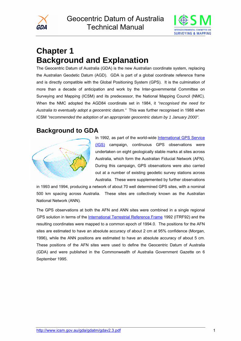
Background to GDA In 1992, as part of the world-wide International GPS Service
(IGS) campaign, continuous GPS observations were
undertaken on eight geologically stable marks at sites across
Australia, which form the Australian Fiducial Network (AFN).
During this campaign, GPS observations were also carried
out at a number of existing geodetic survey stations across
Australia. These were supplemented by further observations
in 1993 and 1994, producing a network of about 70 well determined GPS sites, with a nominal
500 km spacing across Australia. These sites are collectively known as the Australian
National Network (ANN).
The GPS observations at both the AFN and ANN sites were combined in a single regional
GPS solution in terms of the International Terrestrial Reference Frame 1992 (ITRF92) and the
resulting coordinates were mapped to a common epoch of 1994.0. The positions for the AFN
sites are estimated to have an absolute accuracy of about 2 cm at 95% confidence (Morgan,
1996), while the ANN positions are estimated to have an absolute accuracy of about 5 cm.
These positions of the AFN sites were used to define the Geocentric Datum of Australia
(GDA) and were published in the Commonwealth of Australia Government Gazette on 6
September 1995.
http://www.icsm.gov.au/gda/gdatm/gdav2.3.pdf 1

Geocentric Datum of Australia Technical Manual
Commonwealth of Australia Gazette No. GN 35 6 September 1995 Government Departments pg 3369 NEW GEODETIC DATUM FOR AUSTRALIA The meeting of the Inter-governmental Committee on Surveying and Mappingheld in Canberra on 28-29 November 1994 adopted the following new geodeticdatum for Australia and recommended its progressive implementation Australia-wide by 1 January 2000: Designation.- The Geocentric Datum of Australia (GDA).
Reference Ellipsoid – Geodetic Reference System 1980 (GRS80) ellipsoid with a semi-major axis (a) of 6 378 137 metres exactly and an inverse flattening (l/f) of298.257 222 101.
Reference Frame.- The GDA is realised by. the co-ordinates of the following Australian Fiducial Network (AFN) geodetic stations referred to the GRS80ellipsoid determined within the International Earth Rotation Service TerrestrialReference Frame 1992 (ITRF92) at the epoch of 1994.0:
South Latitude East Longitude Ellipsoidal Height AU 012 Alice Springs 23° 40' 12.44592" 133° 53' 07.84757" 603.358 metres AU 013 Karratha 20° 58' 53.17004" 117° 05' 49.87255" 109.246 metres AU 014 Darwin 12° 50' 37.35839" 131° 07' 57.84838" 125.197 metres AU 015 Townsville 19° 20' 50.42839" 146° 46' 30.79057" 587.077 metres AU 016 Hobart 42° 48' 16.98506" 147° 26' 19.43548" 41.126 metres AU 017 Tidbinbilla 35° 23' 57.15627" 148° 58' 47.98425" 665.440 metres AU 019 Ceduna 31° 52' 00.01664" 133° 48' 35.37527" 144.802 metres AU 029 Yaragadee 29° 02' 47.61687" 115° 20' 49.10049" 241.291 metres H. Houghton Chairman Inter-Governmental Committee on Surveying and Mapping
GDA Specifications
Terminology
Datum Geocentric Datum of Australia (GDA)
Geographical coordinate set (latitude
and longitude)
Geocentric Datum of Australia 1994
(GDA94)
Grid coordinates (Universal
Transverse Mercator, using the
GRS80 ellipsoid)
Map Grid of Australia 1994 (MGA94)
http://www.icsm.gov.au/gda/gdatm/gdav2.3.pdf 2
Geocentric Datum of Australia Technical Manual
Definition
Reference Frame ITRF92 (International Terrestrial Reference Frame 1992)
Epoch 1994.0
Ellipsoid GRS80
Semi-major axis (a) 6,378,137.0 metres
Inverse flattening (1/f) 298.257222101
GDA and AGD
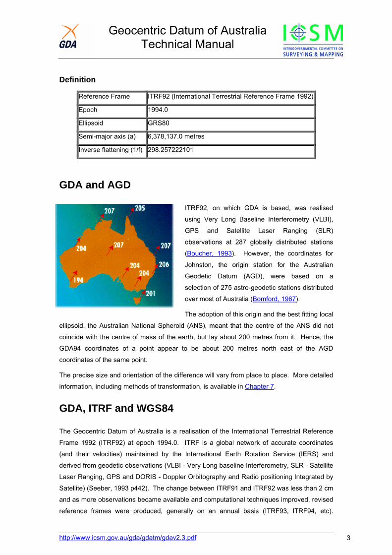
ITRF92, on which GDA is based, was realised
using Very Long Baseline Interferometry (VLBI),
GPS and Satellite Laser Ranging (SLR)
observations at 287 globally distributed stations
(Boucher, 1993). However, the coordinates for
Johnston, the origin station for the Australian
Geodetic Datum (AGD), were based on a
selection of 275 astro-geodetic stations distributed
over most of Australia (Bomford, 1967).
The adoption of this origin and the best fitting local
ellipsoid, the Australian National Spheroid (ANS), meant that the centre of the ANS did not
coincide with the centre of mass of the earth, but lay about 200 metres from it. Hence, the
GDA94 coordinates of a point appear to be about 200 metres north east of the AGD
coordinates of the same point.
The precise size and orientation of the difference will vary from place to place. More detailed
information, including methods of transformation, is available in Chapter 7.
GDA, ITRF and WGS84
The Geocentric Datum of Australia is a realisation of the International Terrestrial Reference
Frame 1992 (ITRF92) at epoch 1994.0. ITRF is a global network of accurate coordinates
(and their velocities) maintained by the International Earth Rotation Service (IERS) and
derived from geodetic observations (VLBI - Very Long baseline Interferometry, SLR - Satellite
Laser Ranging, GPS and DORIS - Doppler Orbitography and Radio positioning Integrated by
Satellite) (Seeber, 1993 p442). The change between ITRF91 and ITRF92 was less than 2 cm
and as more observations became available and computational techniques improved, revised
reference frames were produced, generally on an annual basis (ITRF93, ITRF94, etc).
http://www.icsm.gov.au/gda/gdatm/gdav2.3.pdf 3
Geocentric Datum of Australia Technical Manual
http://www.icsm.gov.au/gda/gdatm/gdav2.3.pdf 4
However, ITRF92 was already sufficiently refined that the change between it and subsequent
ITRF's is only of the order of a couple of centimetres (Boucher, 1994).
The United States Defence Mapping Agency (now NGA - National Geospatial Agency)
enhanced the original WGS84 reference frame, as used by GPS, by re-computing the
coordinates of the GPS Control Segment monitor stations in terms of the ITRF91 at the epoch
of 1994.0 (Swift, 1994 & Malys and Slater, 1994). This enhancement included the
replacement of the WGS84 value for GM with the IERS Standards value (1992) (GM is the
product of the universal gravitational constant and the mass of the earth). The refined
WGS84 reference frame was designated WGS84 (G730) and was implemented in the DMA
GPS "precise" ephemeris processing on 2 January 1994. The WGS84 (G730) coordinate set
for the global GPS monitor stations was implemented by the GPS Master Control Station on
29 June 1994. In September 1996 the coordinates of the GPS control stations were again re-
computed with the new reference frame designated as WGS84 (G873). These new
coordinates were implemented on 29 January 1997 (Malys and Slater, 1997). These
changes would have been undetected by most GPS users, as the effect on GPS applications
(survey and navigation) is not significant. All this has resulted in a WGS84 reference frame
for GPS which "is consistent with the prevailing ITRF at a level of the order of a few
centimetres" (ibid), and ITRF positions may be used as WGS84 for most general applications.
In January 1994 GDA94 and ITRF were in coincidence, but as the Australian tectonic plate is
moving at about 7 cm per year in a north easterly direction there is an increasing difference in
positions in terms of the two systems. This amounts to about 77 cm at the start of 2005. For
differential GPS applications this is not an issue, as both ends of a baseline move at the same
rate. Similarly, for most practical applications where an accuracy of only a metre or greater is
required, GDA94 coordinates can be considered the same as WGS84 (Steed & Luton, 2000).
However, for global applications where an accuracy of better than a metre is required, the
difference must be taken into account. Standard 7-parameter transformations from ITRF to
GDA94 are regularly computed from the known GDA94 and continually updated ITRF
positions of the Australian Regional GPS Network (ARGN) and can be used in these cases to
transform ITRF positions to GDA94.
The ellipsoid recommended by the International Association of Geodesy (IAG) and used with
the GDA, is the Geodetic Reference System 1980 ellipsoid. This ellipsoid was used by the
United States Defense Mapping Agency with WGS84. The parameters of the WGS84
ellipsoid "... are identical to those for the GRS80 ellipsoid with one minor exception. The
coefficient form used for the second degree zonal is that of the WGS84 Earth Gravitational
Model rather than the notation J2 used with GRS80." (DMA, 1987 p3-1) The end result is that
the GRS80 and WGS84 ellipsoids have a very small difference in the inverse flattening, but
this difference is insignificant for most practical applications.
Geocentric Datum of Australia Technical Manual
Ellipsoid GRS80 WGS84
Semi major axis (a) 6,378,137.0 6,378,137.0
Inverse flattening (1/f) 298.257222101 298.257223563
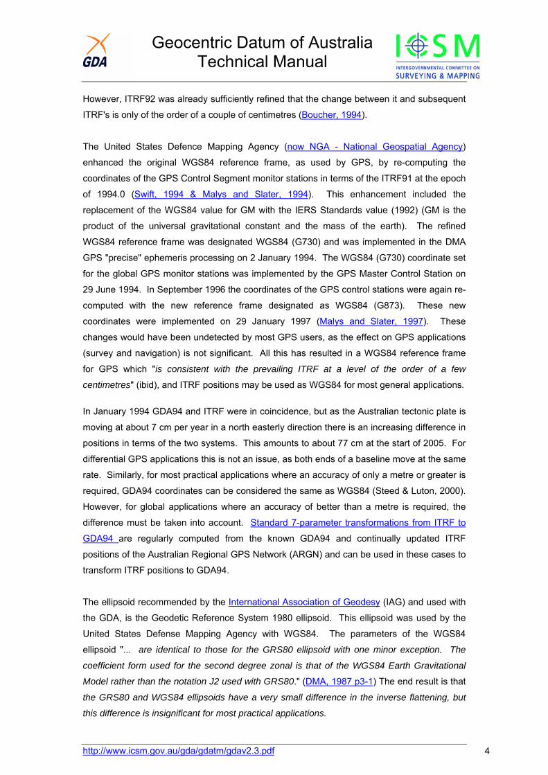
Grid Coordinates Geodetic coordinates (latitude and longitude)
are represented on a map or chart, by
mathematically "projecting" them onto a
surface, which can be laid flat.
The Transverse Mercator system projects
geodetic coordinates onto a concentric
cylinder which is tangent to the equator and
makes contact along one meridian.
To minimise distortion, the earth is "rotated" within the cylinder, to bring a different meridian
into contact with the cylinder, for different areas. This results in north-south bands known as
zones. The true origin for each zone is the intersection of the equator and the contacting
meridian (the central meridian), but a false origin is often used to avoid negative coordinates.
In 1947, the US Army adopted uniform scale factor, false origins and zone size and
numbering for the TM projection and these have since been generally accepted as the
Universal Transverse Mercator Projection (UTM) (Snyder, 1984). This projection was used
with the Australian National Spheroid and AGD66 and AGD84 latitudes and longitudes to
produce the Australian Map Grid 1966 and Australian Map Grid 1984 coordinates (AMG66
and AMG84). It is also used with the GRS80 ellipsoid and GDA94 latitudes and longitudes to
produce Map Grid of Australia 1994 coordinates (MGA94).
Redfearn's formulae (Chapter 5) are used to convert between UTM and geodetic coordinates.
Longitude of initial central meridian (Zone one) 177 degrees west longitude
Zone width 6 degrees
Central scale factor 0.9996
False easting 500,000 m
False northing (in the southern hemisphere) 10,000,000 m
UTM Parameters
http://www.icsm.gov.au/gda/gdatm/gdav2.3.pdf 5
Geocentric Datum of Australia Technical Manual
http://www.icsm.gov.au/gda/gdatm/gdav2.3.pdf 6
Other Coordinates used in Australia With the introduction of the Australian Geodetic Datum in 1966, AGD66 coordinates were
widely adopted but were later replaced in several States by the improved AGD84 coordinates.
However there were also a number of early global coordinate systems, which were used
mainly with satellite navigation systems (Steed, 1990).
Australian Geodetic Datum (AGD)
The Australian Geodetic Datum was the first proclaimed in the Australian Commonwealth
Gazette of 6 October 1966. This proclamation included the parameters of the adopted
ellipsoid, known as the Australian National Spheroid (ANS), and the position of the origin
point - Johnston Geodetic Station.
The coordinates (latitude & longitude) produced by the 1966 national adjustment in terms of
the AGD are known as AGD66 and the equivalent UTM grid coordinates are known as
AMG66.
In 1982 a new national adjustment, referred to as the Geodetic Model of Australia 1982
(GMA82), was performed using all data previously included in the 1966 adjustment as well as
more recent observations. This new adjustment used the same gazetted Australian Geodetic
Datum as the AGD66 adjustment, but also used improved software and included a geoid
model. The coordinates resulting from this adjustment were accepted by the National
Mapping Council in 1984 and are known as Australian Geodetic Datum 1984 (AGD84)
coordinates. The equivalent UTM grid coordinates are known as AMG84
Semi major axis (a) 6,378,160 metres
Inverse Flattening (1/f) 298.25
ANS ellipsoid Parameters
World Geodetic System 1972 (WGS72)
WGS72 was the third approximately geocentric reference frame developed by the United
States Defense Mapping Agency (DMA) to support its activities (previous versions were
WGS60 and WGS66). It was superseded by WGS84, but until 27 January 1987, was used
with the GPS system and prior to 27 January 1989 it was used for the Transit Doppler
navigation system broadcast ephemeris. In the Australian region, WGS72 coordinates differ
from WGS84 and GDA94 coordinates by about 15 metres.
Semi major axis (a) 6,378,135 metres
Inverse Flattening (1/f) 298.26
WGS72 ellipsoid Parameters
Geocentric Datum of Australia Technical Manual
http://www.icsm.gov.au/gda/gdatm/gdav2.3.pdf 7
NSWC-9Z2
This system, which was effectively the same as its predecessor NWL9D, was an
approximately geocentric system used for the Transit Doppler navigation system "precise"
ephemeris.
Semi major axis (a) 6,378,145 metres
Inverse Flattening (1/f) 298.25
NSWC-9Z2 ellipsoid Parameters
"Clarke" Coordinates
In Australia prior to 1966, some twenty different datums, using four different figures of the
earth were used. The most widely used was the Clarke's 1858 ellipsoid:
Semi-major axis (a) 20,926,348 feet
Flattening (f) 294.26
Clarke 1858 Ellipsoid parameters
The rectangular grid coordinate system used in conjunction with the Clarke 1858 spheroid
was called the Australian National Grid (ANG) (NMC, 1976), but was also known as the
Australian Transverse Mercator (ATM). "Coordinates were quoted in yards and were derived
from a Transverse Mercator projection of latitudes and longitudes determined in relation to the
relevant State or local coordinate origin" (NMC 1986, pp 52). A discussion of the
development of this system can be found in Lines (1992, pp315-320).
Central scale factor 1.0 exactly
False Easting * 400,000 yards
False Northing * 800,000 yards
Zone Width 5 degrees
Initial Central meridian (Zone one) 116 degrees east longitude.
ANG Parameters * The true origin for each zone of the ANG was the intersection of the central meridian and
S34° latitude, with the false origin 800,000 yards further south.
(Note: this is equivalent to a false northing of 4,915,813.467 yards from the equator =
4,115,813.469 + 800,000 yards). In Tasmania, to prevent negative coordinates, a further
1,000,000 yards was added to the false northing (total 1,800,000 yards) (AHQ Survey, 1942).
Geocentric Datum of Australia Technical Manual
Chapter 2 Reduction of Measured Distances to the Ellipsoid
Excel Spreadsheet – Calculation of Reduced Distance
Due to the effects of atmospheric refraction, the light waves or microwaves used by EDM follow a curved
path. Before this curved wave path distance can be used for any geodetic computations, it should be
reduced to the surface of the ellipsoid by the application of both physical and geometric corrections.
Figure 2.1 illustrates the situation.
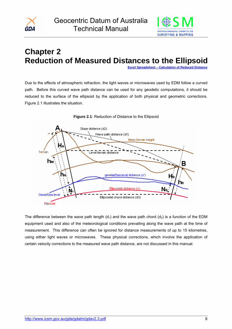
Figure 2.1: Reduction of Distance to the Ellipsoid
The difference between the wave path length (d1) and the wave path chord (d2) is a function of the EDM
equipment used and also of the meteorological conditions prevailing along the wave path at the time of
measurement. This difference can often be ignored for distance measurements of up to 15 kilometres,
using either light waves or microwaves. These physical corrections, which involve the application of
certain velocity corrections to the measured wave path distance, are not discussed in this manual.
http://www.icsm.gov.au/gda/gdatm/gdav2.3.pdf 8
Geocentric Datum of Australia Technical Manual
http://www.icsm.gov.au/gda/gdatm/gdav2.3.pdf 9
Combined Formula The reduction of the wave path chord distance (d 2), to the ellipsoidal chord distance (d3), can be given as
a single rigorous formula (Clarke, 1966, p299):
d 3=[(d22 - (hA - hB) ) / (1+ hB
2A/Rα) (1 + hBB/Rα )]½
The ellipsoidal chord distance (d3) is then easily reduced to the ellipsoidal distance:
s = d3[1 + (d32/24Rα
2 + 3d34/640Rα
4 + ...]
where Rα is the radius of curvature in the azimuth of the line.
For a distance of 30 kilometres in the Australian region the chord-to-arc correction is 0.028 metres. For a
distance of 50 kilometres, the correction reaches about 0.13 metre and it is more than 1 metre at 100 km.
The second term in the chord-to-arc correction is less than 1 mm for lines up to 100 km, anywhere in
Australia and usually can be ignored.
Separate Formulae The combined formula above includes the slope and ellipsoid level corrections. The slope correction
reduces the wave path chord (d2) to a horizontal distance at the mean elevation of the terminals of the
line and the ellipsoid level correction reduces the horizontal distance to the ellipsoid chord distance (d3).
The chord-to-arc correction is then applied to the ellipsoid chord distance, as with the combined formula,
to give the ellipsoidal distance (s).
Slope correction = (d22-Dh2)½ - d2
Ellipsoidal correction =(hm/Rα)(d22 - D h2)½
Chord-to-arc correction =+ d33/24Rα
2 {+ 3d35/640Rα
4 + ...}
Heights in Distance Reduction The formulae given in this chapter use ellipsoidal heights (h). If the geoid-ellipsoid separation (Chapter 9
- N value) is ignored and only the height above the geoid (H - the orthometric or AHD height) is used, an
error of 1 part per million (ppm) will be introduced for every 6½ metres of N value (plus any error due to
the change in N value along the line). As the N value in terms of GDA varies from -35 metres in
southwest Australia, to about 70 metres in northern Queensland, errors from -5 to almost 11 ppm could
be expected. Of course there are areas where the N value is small and the error would also be small.
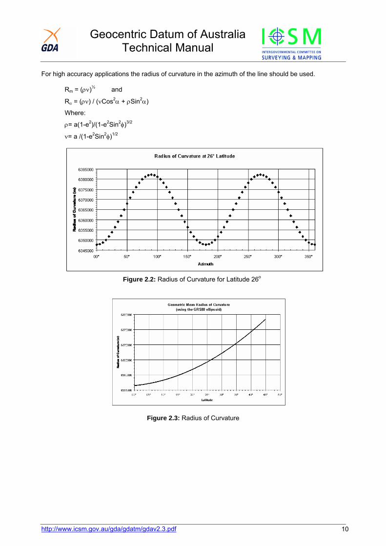
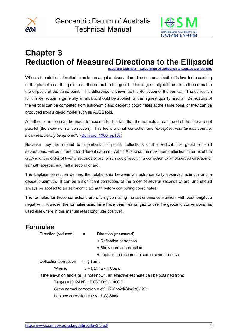
Radius of Curvature The radius of curvature is a function of latitude and for many applications the geometric mean radius (Rm)
(Figure 2.2), can be used rather than the radius in the azimuth of the line (Rα). However, there can be a
large difference between the geometric mean radius and the radius in the azimuth of the line.
Geocentric Datum of Australia Technical Manual
For high accuracy applications the radius of curvature in the azimuth of the line should be used.
Rm = (ρν)½ and
Rα = (ρν) / (νCos2α + ρSin2α)
Where:
ρ= a(1-e2)/(1-e2Sin2φ)3/2
ν= a /(1-e2Sin2φ)1/2
Figure 2.2: Radius of Curvature for Latitude 26o
Figure 2.3: Radius of Curvature
http://www.icsm.gov.au/gda/gdatm/gdav2.3.pdf 10
Geocentric Datum of Australia Technical Manual
http://www.icsm.gov.au/gda/gdatm/gdav2.3.pdf 11
Chapter 3 Reduction of Measured Directions to the Ellipsoid
Excel Spreadsheet – Calculation of Deflection & Laplace Corrections
When a theodolite is levelled to make an angular observation (direction or azimuth) it is levelled according
to the plumbline at that point, i.e. the normal to the geoid. This is generally different from the normal to
the ellipsoid at the same point. This difference is known as the deflection of the vertical. The correction
for this deflection is generally small, but should be applied for the highest quality results. Deflections of
the vertical can be computed from astronomic and geodetic coordinates at the same point, or they can be
produced from a geoid model such as AUSGeoid.
A further correction can be made to account for the fact that the normals at each end of the line are not
parallel (the skew normal correction). This too is a small correction and "except in mountainous country,
it can reasonably be ignored". (Bomford, 1980, pp107)
Because they are related to a particular ellipsoid, deflections of the vertical, like geoid ellipsoid
separations, will be different for different datums. Within Australia, the maximum deflection in terms of the
GDA is of the order of twenty seconds of arc, which could result in a correction to an observed direction or
azimuth approaching half a second of arc.
The Laplace correction defines the relationship between an astronomically observed azimuth and a
geodetic azimuth. It can be a significant correction, of the order of several seconds of arc, and should
always be applied to an astronomic azimuth before computing coordinates.
The formulae for these corrections are often given using the astronomic convention, with east longitude
negative. However, the formulae used here have been rearranged to use the geodetic conventions, as
used elsewhere in this manual (east longitude positive).
Formulae Direction (reduced) = Direction (measured)
+ Deflection correction
+ Skew normal correction
+ Laplace correction (laplace for azimuth only)
Deflection correction = -ζ Tan e
Where: ζ = ξ Sin α - η Cos α
If the elevation angle (e) is not known, an effective estimate can be obtained from:
Tan(e) = [(H2-H1) . 0.067 D2] / 1000 D
Skew normal correction = e'2 H2 Cos2ΦSin(2α) / 2R
Laplace correction = (λA - λ G) SinΦ
Geocentric Datum of Australia Technical Manual
http://www.icsm.gov.au/gda/gdatm/gdav2.3.pdf 12
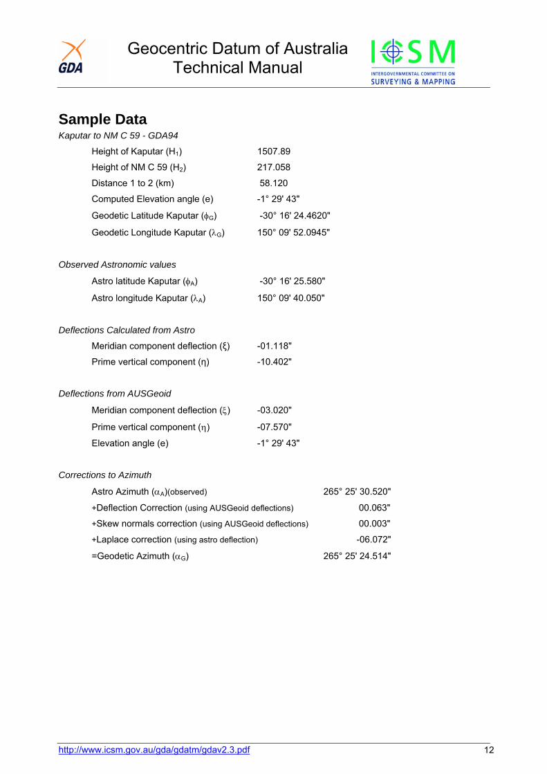
Sample Data Kaputar to NM C 59 - GDA94
Height of Kaputar (H1) 1507.89
Height of NM C 59 (H2) 217.058
Distance 1 to 2 (km) 58.120
Computed Elevation angle (e) -1° 29' 43"
Geodetic Latitude Kaputar (φG) -30° 16' 24.4620"
Geodetic Longitude Kaputar (λG) 150° 09' 52.0945"
Observed Astronomic values
Astro latitude Kaputar (φA) -30° 16' 25.580"
Astro longitude Kaputar (λA) 150° 09' 40.050"
Deflections Calculated from Astro
Meridian component deflection (ξ) -01.118" Prime vertical component (η) -10.402"
Deflections from AUSGeoid
Meridian component deflection (ξ) -03.020"
Prime vertical component (η) -07.570"
Elevation angle (e) -1° 29' 43"
Corrections to Azimuth
Astro Azimuth (αA)(observed) 265° 25' 30.520"
+Deflection Correction (using AUSGeoid deflections) 00.063"
+Skew normals correction (using AUSGeoid deflections) 00.003"
+Laplace correction (using astro deflection) -06.072"
=Geodetic Azimuth (αG) 265° 25' 24.514"
Geocentric Datum of Australia Technical Manual
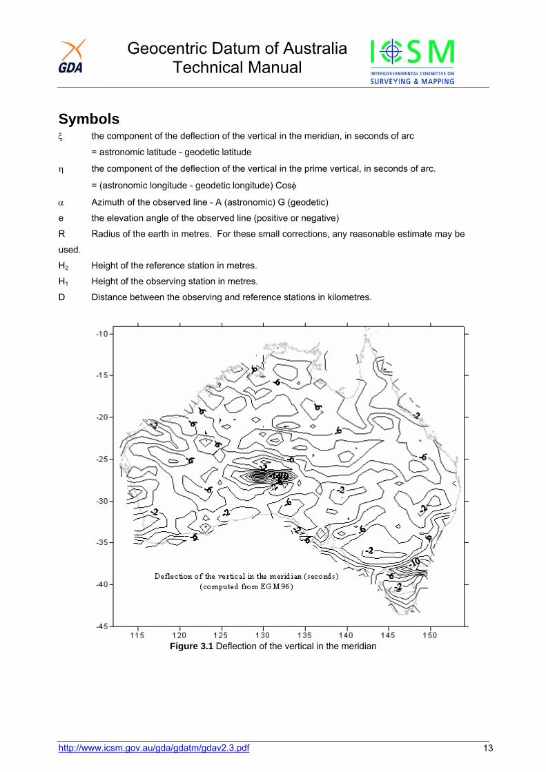
Symbols ξ the component of the deflection of the vertical in the meridian, in seconds of arc
= astronomic latitude - geodetic latitude
η the component of the deflection of the vertical in the prime vertical, in seconds of arc.
= (astronomic longitude - geodetic longitude) Cosφ
α Azimuth of the observed line - A (astronomic) G (geodetic)
e the elevation angle of the observed line (positive or negative)
R Radius of the earth in metres. For these small corrections, any reasonable estimate may be
used.
H2 Height of the reference station in metres.
H1 Height of the observing station in metres.
D Distance between the observing and reference stations in kilometres.
Figure 3.1 Deflection of the vertical in the meridian
http://www.icsm.gov.au/gda/gdatm/gdav2.3.pdf 13

Geocentric Datum of Australia Technical Manual
Figure 3.2 Deflection of the vertical in the prime vertical
http://www.icsm.gov.au/gda/gdatm/gdav2.3.pdf 14

Geocentric Datum of Australia Technical Manual
http://www.icsm.gov.au/gda/gdatm/gdav2.3.pdf 15
Chapter 4 Computations on the Ellipsoid
Excel Spreadsheet – Vincenty's Formulae (Direct and Inverse)
There are a number of formulae available to calculate accurate geodetic positions, azimuths and
distances on the ellipsoid (Bomford, 1980). Vincenty's formulae (Vincenty, 1975) may be used for lines
ranging from a few cm to nearly 20,000 km, with millimetre accuracy. The formulae have been
extensively tested for the Australian region, by comparison with results from other formulae (Rainsford,
1955 & Sodano, 1965).
Vincenty's Inverse formulae Given: latitude and longitude of two points (φ 1, λ1 and φ 2, λ2),
Calculate: the ellipsoidal distance (s) and forward and reverse azimuths between the points (α1-2, α2-1).
TanU1 = (1-f) Tanφ 1
TanU2 = (1-f) Tanφ 2Starting with the approximation,
λ = ω = λ2 - λ1
Iterate the following equations, until there is no significant change in σ:
Sin2σ = (CosU2 Sinλ)2 + (CosU1 SinU2 - SinU1 CosU2 Cosλ)2
Cosσ = SinU1 SinU2 + CosU1 CosU2 Cosλ
Tanσ = Sinσ / Cosσ
Sinα = CosU1 CosU2 Sinλ / Sinσ
Cos2σm = Cosσ - (2SinU1 SinU2 / Cos2α)
C = (f/16) Cos2α[4+f(4-3 Cos2α)]
λ = ω + (1-C) f Sinα{σ + C Sinσ[Cos2σm + C Cosσ (-1 + 2Cos22σm)]}
Then:
u2 = cos2α(a2-b2)/b2
A = 1 + (u2/16384) {4096 + u2[-768+ u2(320-175u2)]}
B= (u2/1024) {256 + u2[-128+ u2(74-47u2)]}
Δσ = BSinσ {Cos2σm + (B/4) [Cosσ (-1+2Cos22σm)-(B/6) Cos2σm (-3+4Sin2σ)(-3+4Cos22σm)]}
s = bA(σ - Δσ)
Tanα1-2 = (CosU2 Sinλ) / (CosU1 SinU2 - SinU1 CosU2 Cosλ)
Tanα2-1 = (CosU1 Sinλ) / (-SinU1 CosU2 + CosU1 SinU2 Cosλ)

Geocentric Datum of Australia Technical Manual
http://www.icsm.gov.au/gda/gdatm/gdav2.3.pdf 16
Vincenty's Direct formulae Given: latitude and longitude of a point (φ 1, λ1) and the geodetic azimuth (α 1-2) and ellipsoidal distance to
a second point (s),
Calculate: the latitude and longitude of the second point (φ 2, λ2) and the reverse azimuth (α 2-1).
TanU1 = (1-f) Tanφ1
Tanσ1= TanU1 /Cosα1-2
Sinα = CosU1 Sinα1-2
u2 = cos2α(a2-b2)/b2
A = 1 + (u2/16384) {4096 + u2[-768+ u2(320-175u2)]}
B= (u2/1024) {256 + u2[-128+ u2(74-47u2)]}
Starting with the approximation
σ = (s/bA)
Iterate the following three equations until there is no significant change in �
2σm = 2σ1 + σ
Δσ = BSinσ {Cos2σm + (B/4) [Cosσ (-1+2Cos22σm)-(B/6) Cos2σm (-3+4Sin2σ)(-3+4Cos22σm)]}
σ = (s/bA) + Δσ
Then:
Tanφ2 = (Sin U1 Cosσ + CosU1 Sinσ Cosα1-2) / {(1-f)[Sin2α+(SinU1 Sinσ - CosU1 Cosσ Cosα1-2)2]½}
Tanλ = (Sinσ Sinα1-2) / (CosU1 Cosσ - SinU1 Sinσ Cosα1-2)
C = (f/16) Cos2α[4 + f (4-3 Cos2α)]
ω = λ-(1-C) f Sinα{σ+CSinσ[Cos2σm+C Cosσ (-1+2Cos22σm)]}
λ2 = λ1 + ω
Tanα2-1 = (Sinα) / (-SinU1 Sinσ + CosU1 Cosσ Cosα1-2)
Note:
• "The inverse formulae may give no solution over a line between two nearly antipodal points. This will occur when λ is greater than π in absolute value". (Vincenty, 1975)
• In Vincenty (1975) L is used for the difference in longitude, however for consistency with other formulae in this Manual, ω is used here.
• Variables specific to Vincenty's formulae are shown below, others common throughout the manual are shown in the Glossary.

Geocentric Datum of Australia Technical Manual
http://www.icsm.gov.au/gda/gdatm/gdav2.3.pdf 17
Symbols α Azimuth of the geodesic at the equator. (Forward 1-2, Reverse 2-1) U Reduced latitude λ Difference in longitude on an auxiliary sphere (λ1 & λ2 are the geodetic
longitudes of points 1 & 2) σ Angular distance on a sphere, from point 1 to point 2 σ1 Angular distance on a sphere, from the equator to point 1 σ2 Angular distance on a sphere, from the equator to point 2 σm Angular distance on a sphere, from the equator to the midpoint of the
line from point 1 to point 2 u, A, B, C
Internal variables
Sample Data
Flinders Peak -37°57. 03.72030" 144°25. 29.52440" Buninyong -37°39. 10.15610" 143°55. 35.38390" Ellipsoidal Distance 54,972.271 m Forward Azimuth 306°52. 05.37" Reverse Azimuth 127°10. 25.07"
Geocentric Datum of Australia Technical Manual
Chapter 5 Conversion between Ellipsoidal and Grid Coordinates
Excel Spreadsheet – Redfearn's Formulae
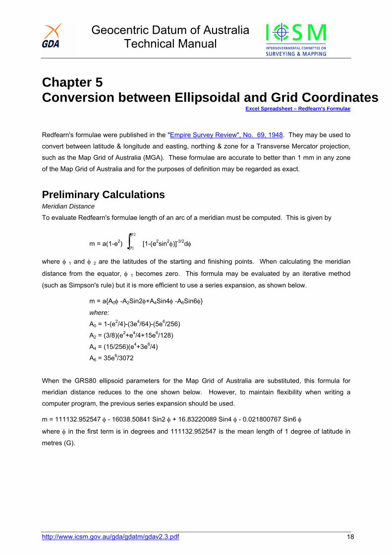
Redfearn's formulae were published in the "Empire Survey Review", No. 69, 1948. They may be used to
convert between latitude & longitude and easting, northing & zone for a Transverse Mercator projection,
such as the Map Grid of Australia (MGA). These formulae are accurate to better than 1 mm in any zone
of the Map Grid of Australia and for the purposes of definition may be regarded as exact.
Preliminary Calculations Meridian Distance
To evaluate Redfearn's formulae length of an arc of a meridian must be computed. This is given by
m = a(1-e2) [1-(e∫2
1
ϕ
ϕ2sin2φ)]-3/2dφ
where φ 1 and φ 2 are the latitudes of the starting and finishing points. When calculating the meridian
distance from the equator, φ 1 becomes zero. This formula may be evaluated by an iterative method
(such as Simpson's rule) but it is more efficient to use a series expansion, as shown below.
m = a{A0φ -A2Sin2φ+A4Sin4φ -A6Sin6φ}
where:
A0 = 1-(e2/4)-(3e4/64)-(5e6/256)
A2 = (3/8)(e2+e4/4+15e6/128)
A4 = (15/256)(e4+3e6/4)
A6 = 35e6/3072
When the GRS80 ellipsoid parameters for the Map Grid of Australia are substituted, this formula for
meridian distance reduces to the one shown below. However, to maintain flexibility when writing a
computer program, the previous series expansion should be used.
m = 111132.952547 φ - 16038.50841 Sin2 φ + 16.83220089 Sin4 φ - 0.021800767 Sin6 φ
where φ in the first term is in degrees and 111132.952547 is the mean length of 1 degree of latitude in
metres (G).
http://www.icsm.gov.au/gda/gdatm/gdav2.3.pdf 18
Geocentric Datum of Australia Technical Manual
http://www.icsm.gov.au/gda/gdatm/gdav2.3.pdf 19
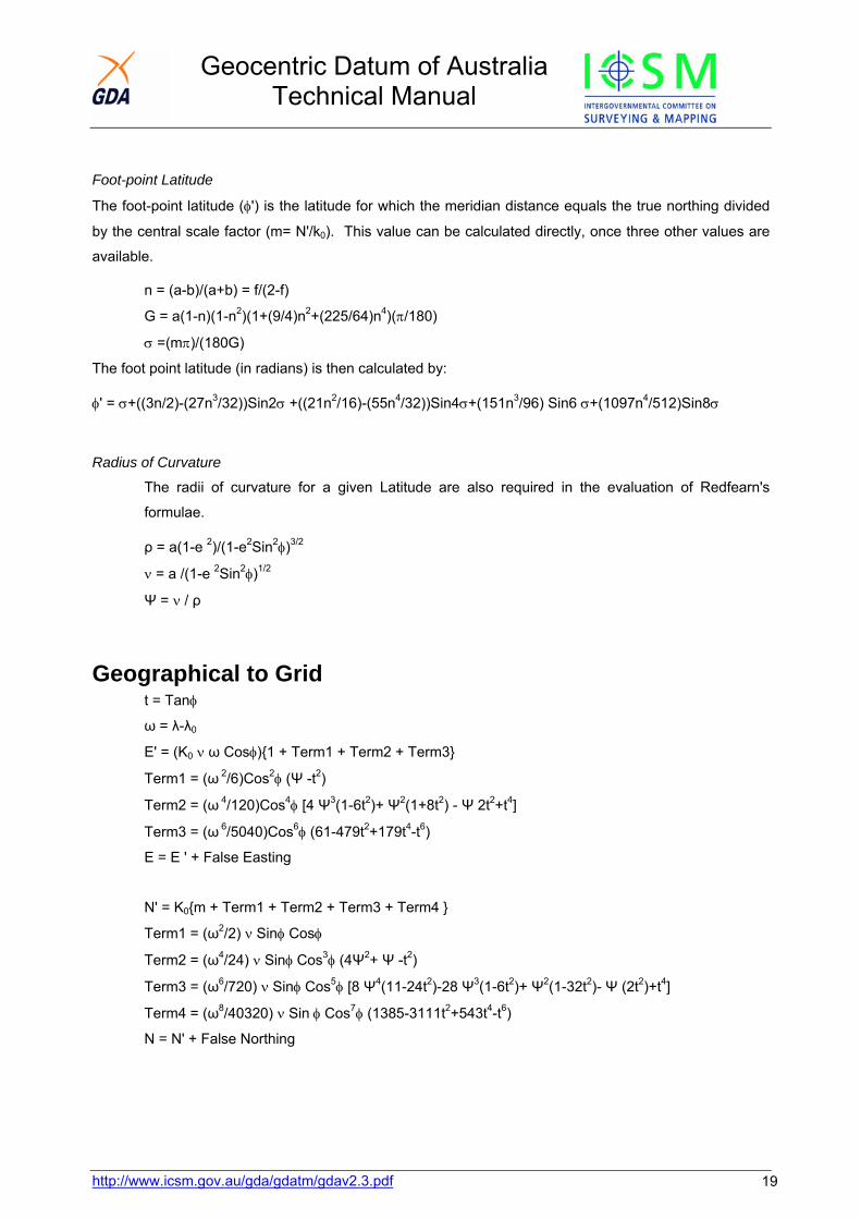
Foot-point Latitude
The foot-point latitude (φ') is the latitude for which the meridian distance equals the true northing divided
by the central scale factor (m= N'/k0). This value can be calculated directly, once three other values are
available.
n = (a-b)/(a+b) = f/(2-f)
G = a(1-n)(1-n2)(1+(9/4)n2+(225/64)n4)(π/180)
σ =(mπ)/(180G)
The foot point latitude (in radians) is then calculated by:
φ' = σ+((3n/2)-(27n3/32))Sin2σ +((21n2/16)-(55n4/32))Sin4σ+(151n3/96) Sin6 σ+(1097n4/512)Sin8σ
Radius of Curvature
The radii of curvature for a given Latitude are also required in the evaluation of Redfearn's
formulae.
ρ = a(1-e 2)/(1-e2Sin2φ)3/2
ν = a /(1-e 2Sin2φ)1/2
Ψ = ν / ρ
Geographical to Grid t = Tanφ
ω = λ-λ0
E' = (K0 ν ω Cosφ){1 + Term1 + Term2 + Term3}
Term1 = (ω 2/6)Cos2φ (Ψ -t2)
Term2 = (ω 4/120)Cos4φ [4 Ψ3(1-6t2)+ Ψ2(1+8t2) - Ψ 2t2+t4]
Term3 = (ω 6/5040)Cos6φ (61-479t2+179t4-t6)
E = E ' + False Easting
N' = K0{m + Term1 + Term2 + Term3 + Term4 }
Term1 = (ω2/2) ν Sinφ Cosφ
Term2 = (ω4/24) ν Sinφ Cos3φ (4Ψ2+ Ψ -t2)
Term3 = (ω6/720) ν Sinφ Cos5φ [8 Ψ4(11-24t2)-28 Ψ3(1-6t2)+ Ψ2(1-32t2)- Ψ (2t2)+t4]
Term4 = (ω8/40320) ν Sin φ Cos7φ (1385-3111t2+543t4-t6)
N = N' + False Northing
Geocentric Datum of Australia Technical Manual
http://www.icsm.gov.au/gda/gdatm/gdav2.3.pdf 20
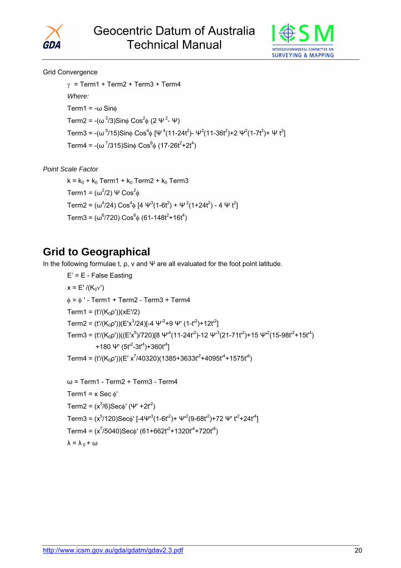
Grid Convergence
γ = Term1 + Term2 + Term3 + Term4
Where:
Term1 = -ω Sinφ
Term2 = -(ω 3/3)Sinφ Cos2φ (2 Ψ 2- Ψ)
Term3 = -(ω 5/15)Sinφ Cos4φ [Ψ 4(11-24t2)- Ψ3(11-36t2)+2 Ψ2(1-7t2)+ Ψ t2]
Term4 = -(ω 7/315)Sinφ Cos6φ (17-26t2+2t4)
Point Scale Factor
k = k0 + k0 Term1 + k0 Term2 + k0 Term3
Term1 = (ω2/2) Ψ Cos2φ
Term2 = (ω4/24) Cos4φ [4 Ψ3(1-6t2) + Ψ 2(1+24t2) - 4 Ψ t2]
Term3 = (ω6/720) Cos6φ (61-148t2+16t4)
Grid to Geographical In the following formulae t, ρ, ν and Ψ are all evaluated for the foot point latitude.
E’ = E - False Easting
x = E' /(K0ν')
φ = φ ' - Term1 + Term2 - Term3 + Term4
Term1 = (t'/(K0ρ'))(xE'/2)
Term2 = (t'/(K0ρ'))(E'x3/24)[-4 Ψ’2+9 Ψ' (1-t'2)+12t'2]
Term3 = (t'/(K0ρ'))((E'x5)/720)[8 Ψ'4(11-24t'2)-12 Ψ’3(21-71t'2)+15 Ψ'2(15-98t'2+15t'4)
+180 Ψ' (5t'2-3t'4)+360t'4]
Term4 = (t'/(K0ρ'))(E' x7/40320)(1385+3633t'2+4095t'4+1575t'6)
ω = Term1 - Term2 + Term3 - Term4
Term1 = x Sec φ'
Term2 = (x3/6)Secφ' (Ψ' +2t'2)
Term3 = (x5/120)Secφ' [-4Ψ'3(1-6t'2)+ Ψ'2(9-68t'2)+72 Ψ' t'2+24t'4]
Term4 = (x7/5040)Secφ' (61+662t'2+1320t'4+720t'6)
λ = λ 0 + ω

Geocentric Datum of Australia Technical Manual
http://www.icsm.gov.au/gda/gdatm/gdav2.3.pdf 21
Grid Convergence
x = E'/k0 ν'
t' = Tan φ'
γ = Term1 + Term2 + Term3 + Term4
Term1 = -t' x
Term2 = (t' x3/3)(-2 Ψ'2+3 Ψ' +t'2)
Term3 = (-t' x5/15)[Ψ'4(11-24t'2)-3 Ψ’3(8-23t'2)+5 Ψ'2(3-14t'2)+30 Ψ' t'2+3t'4]
Term4 = (t' x7/315)(17+77t'2+105t'4+45t'6)
Point Scale
x = (E'2/k02 ρ'ν')
K = k0 + k0Term1 + k0Term2 + k0Term3
Term1 = x/2
Term2 = (x2/24)[4 Ψ' (1-6t'2)-3(1-16t'2)-24t'2/ Ψ']
Term3 = x3/720
Sample Data
Flinders Peak MGA94 (zone 55) E 273,741.297 N 5,796,489.777
GDA94 -37° 57' 03.7203" 144° 25' 29.5244"
Convergence -1°35' 03.65"
Point scale factor 1.000 230 56
Geocentric Datum of Australia Technical Manual
http://www.icsm.gov.au/gda/gdatm/gdav2.3.pdf 22
Chapter 6 Grid Calculations
Excel Spreadsheet – Grid Calculations
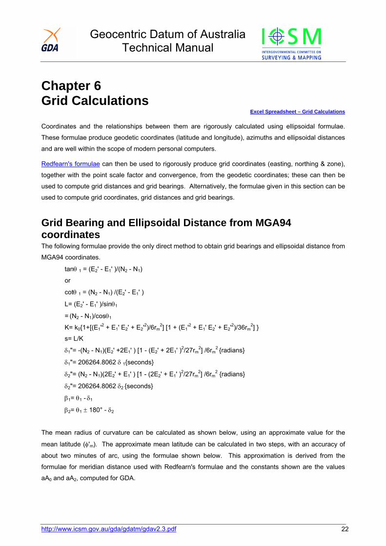
Coordinates and the relationships between them are rigorously calculated using ellipsoidal formulae.
These formulae produce geodetic coordinates (latitude and longitude), azimuths and ellipsoidal distances
and are well within the scope of modern personal computers.
Redfearn's formulae can then be used to rigorously produce grid coordinates (easting, northing & zone),
together with the point scale factor and convergence, from the geodetic coordinates; these can then be
used to compute grid distances and grid bearings. Alternatively, the formulae given in this section can be
used to compute grid coordinates, grid distances and grid bearings.
Grid Bearing and Ellipsoidal Distance from MGA94 coordinates The following formulae provide the only direct method to obtain grid bearings and ellipsoidal distance from
MGA94 coordinates.
tanθ 1 = (E2' - E1' )/(N2 - N1)
or
cotθ 1 = (N2 - N1) /(E2' - E1' )
L= (E2' - E1' )/sinθ1
= (N2 - N1)/cosθ1
K= k0{1+[(E1'2 + E1' E2' + E2'2)/6rm2] [1 + (E1'2 + E1' E2' + E2'2)/36rm
2] }
s= L/K
δ1"= -(N2 - N1)(E2' +2E1' ) [1 - (E2' + 2E1' )2/27rm2] /6rm
2 {radians}
δ1"= 206264.8062 δ 1{seconds}
δ2"= (N2 - N1)(2E2' + E1' ) [1 - (2E2' + E1' )2/27rm2] /6rm
2 {radians}
δ2"= 206264.8062 δ2 {seconds}
β1= θ1 - δ1
β2= θ1 ± 180° - δ2
The mean radius of curvature can be calculated as shown below, using an approximate value for the
mean latitude (φ'm). The approximate mean latitude can be calculated in two steps, with an accuracy of
about two minutes of arc, using the formulae shown below. This approximation is derived from the
formulae for meridian distance used with Redfearn's formulae and the constants shown are the values
aA0 and aA2, computed for GDA.

Geocentric Datum of Australia Technical Manual
http://www.icsm.gov.au/gda/gdatm/gdav2.3.pdf 23
N' = N - False Northing
N'm= (N'1 + N'2)/2
φ'm(1st approx)= (N'm/k0)/111132.952
φ'm(2nd approx) = ((N'm/k0) + 16038.508 sin2φ'm)/111132.952
ρm= a(1 - e2) / (1-e2sin2φ'm)3/2
νm= a / (1-e2sin2φ'm)1/2
rm2= ρm ν mk0
2
MGA94 Coordinates from Grid bearing and Ellipsoidal Distance This computation is commonly used when the coordinates of one station are known and the grid bearing
and ellipsoidal distance from this station to an adjacent station have been determined. The bearing and
distance are applied to the coordinates of the known station to derive the coordinates of the unknown
station and the reverse grid bearing. The formulae shown are accurate to 0.02"and 0.1 ppm over any 100
kilometre line in an MGA zone. For lower order surveys:
• the underlined terms are often omitted,
• the latitude function 1/6r2 becomes a constant and,
• the formulae for K and δ are replaced by simplified versions.
Formulae
First calculate approximate coordinates for the unknown station:
• E'1= E1 - 500,000
• E'2 ≈ E'1 + k1 s sinβ1
• N2 - N1≈ k1 s cosβ1
If not already known the point scale factor (k1) may be approximated by:
k1≈ 0.9996 + 1.23E'2 10-14
K= k0{1 + [(E1'2 + E'1E'2+ E'22)/6rm2] [1 + (E'12 + E'1E'2+ E'22)/36rm
2] }
L= sK
sinδ1= -(N2-N1)(E'2+2E'1) [1-(E'2+ 2E'1)2/27 rm2 ] /6rm
2
θ = β 1 + δ 1
sinδ2= (N2-N1)(2E'2+E'1) [1-(2E'2+ E'1)2/27 rm2 ] /6rm
2
β2= θ ± 180° - δ2
ΔE= L sinθ
ΔN= L cosθ
E2= E1 + ΔE
N2= N1 + ΔN

Geocentric Datum of Australia Technical Manual
http://www.icsm.gov.au/gda/gdatm/gdav2.3.pdf 24
The mean radius of curvature can be calculated as shown below, using an approximate value for the
mean latitude (φ'm). The approximate mean latitude can be calculated in two steps, with an accuracy of
about two minutes of arc, using the formulae shown below. This approximation is derived from the
formulae for meridian distance used with Redfearn's formulae and the constants shown are the values
aA0 and aA2, computed for GDA.
N' = N - False Northing
N'm= (N'1 + N'2)/2
φ'm(1st approx)= (N'm/k0)/111132.952
φ'm(2nd approx) = ((N'm/k0) + 16038.508 sin2φ'm)/111132.952
ρm= a(1 - e2) / (1-e2sin2φ'm)3/2
νm= a / (1-e2sin2φ'm)1/2
rm2= ρm ν mk0
2
Zone to Zone Transformations If a point lies within ½° of a zone boundary, it is possible to compute the grid coordinate of the point in
terms of the adjacent zone. This can be done by:
1. converting the known grid coordinates to latitude and longitude using Redfearn's formulae, and
then converting back to grid coordinates in terms of the adjacent zone, or
2. using the formulae shown below (Jordan-Eggert, 1941 and Grossman, 1964). These formulae
have an accuracy of 10 mm anywhere within ½° of a zone boundary.
Formulae
tanJ1 = [ωZ2cos2φZ (1 + 31tan2φ Z) - 6(1 + e'2cos2φZ)]/ [18ωZsinφZ (1 + e'2cos2φZ)]
H1 = -3ωZ2 sinφZ cosφZ/(ρ ZcosJ1)
E2 = 500000 - E'Z+ (E'1- E'Z)cos2γ Z - (N1 - NZ)sin2γ Z + H1L2sin(2θZ + J1)
N2 = NZ + (N1 - NZ)cos2γ Z + (E1' - EZ' )sin2γ Z + H1L2cos(2θZ + J1)
where:
Z is a point on the zone boundary,
E1, N1 are the known coordinates of the point to be transformed,
E2, N2 are the coordinates of the point in terms of the adjacent zone,
θZ is the plane bearing from Z to the point to be transformed.
Geocentric Datum of Australia Technical Manual
http://www.icsm.gov.au/gda/gdatm/gdav2.3.pdf 25
Traverse Computation with Grid Coordinates, using Arc-to-Chord Corrections and Line Scale Factors With the power of modern computers, traverses can be rigorously computed on the ellipsoid, using
formulae such as those shown in Chapter 4. The geographic results from these computations can then
be rigorously converted to grid coordinates using Redfearn's formulae. However if necessary, the
computation can be varied to suit the requirements of the job:
• the arc-to-chord corrections and line scale factors can be ignored and the traverse computed
using the formulae of plane trigonometry;
• if good quality maps showing the MGA94 Grid are available, traverse stations may be plotted by
inspection and the approximate coordinates scaled with sufficient precision to enable computation
of the arc-to-chord corrections and line scale factors;
• the arc-to-chord corrections and line scale factors can be computed precisely, and the method
becomes first order anywhere in a MGA94 grid zone.
The precision obtained should be closely balanced against the labour involved, though with modern
Personal Computers and available software, the difference between a rigorous and approximate
calculation is trivial. Prior to precise computation, approximate coordinates and bearings may be carried
through the traverse, using uncorrected field measurements, to ensure that the observations are free of
gross errors. A diagram of the traverse, approximately to scale, is often useful.
Basic Outline There are many ways of arranging the computation. Essentially, the work is split into stages:
1. Approximate Eastings and Northings are computed from observed angles and distances;
2. Arc-to-chord corrections and line scale factors are computed from the approximate coordinates
and applied to the observations to give plane angles and plane distances;
3. Precise coordinates are computed by plane trigonometry;
4. Misclosure in grid bearing and position is analysed and the traverse or figure adjusted as
required.
For precise computation, each line is rigorously computed before the next line is calculated, so that errors
in the approximate coordinates do not accumulate. True Eastings (E') and differences in northing (ΔN)
are the quantities carried through the computation. Sign conventions may be disregarded and signs
determined by inspection of a traverse diagram.
Geocentric Datum of Australia Technical Manual
http://www.icsm.gov.au/gda/gdatm/gdav2.3.pdf 26
Formulae and Symbols
If the underlined terms shown in the preceding sections of this chapter are omitted, the errors for a 100
kilometre line running north and south on a zone boundary do not exceed 0.08" in bearing and 0.25 ppm
in distance. For traverses of lower order, simplified formulae can be used. For short lines near a central
meridian it may be possible to omit the arc-to-chord corrections and line scale factors and compute the
traverse with observed angles and distances, using the formulae of plane trigonometry.
If the symbol δ21 is used for the arc-to-chord correction at station 2 to station 1 and δ23 for the correction at
station 2 to station 3, and the angles are measured clockwise from station 1 to station 3, then the angle P2
(plane) at station 2 is obtained from the angle 02 (observed) by:
P2 = 02 + δ23 - δ21
where angles are measured clockwise only.
Computations of ARC-TO-CHORD Corrections and scale factors
Although there are several ways of arranging the computation, the following is recommended:
1. Compute the grid bearing to the "forward" station by applying the observed horizontal angle at the
"occupied" station to the known grid bearing of the "rear" station;
2. Compute the point scale factor at the "occupied" station and multiply the ellipsoidal distance to
the "forward" station by this factor;
3. Using the distance obtained and the forward grid bearing, compute approximate coordinates of
the "forward" station by plane trigonometry;
4. Using the coordinates of the "occupied" station and the approximate coordinates of the "forward"
station, compute the arc-to-chord correction at the "occupied" station and the line scale factor. If
the line crosses the central meridian, (E1 , E2) is negative;
5. Add the arc-to-chord correction to the forward grid bearing to obtain the plane bearing and
multiply the spheroidal distance by the line scale factor to obtain the plane distance;
6. Using the plane bearing and plane distance, compute the coordinates of the "forward" station by
plane trigonometry;
7. Compute the arc-to-chord correction from the new station to the previously occupied station and
add this to the plane bearing reversed by 180° to obtain the reverse grid bearing from the new
station.
The above process is repeated for each new line of a traverse with the reverse grid bearing of the
previous line becoming the known grid bearing to the rear station.
Geocentric Datum of Australia Technical Manual
http://www.icsm.gov.au/gda/gdatm/gdav2.3.pdf 27
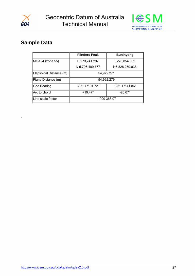
Sample Data
Flinders Peak Buninyong
MGA94 (zone 55) E 273,741.297
N 5,796,489.777
E228,854.052
N5,828,259.038
Ellipsoidal Distance (m) 54,972.271
Plane Distance (m) 54,992.279
Grid Bearing 305° 17' 01.72" 125° 17' 41.86"
Arc to chord +19.47" -20.67"
Line scale factor 1.000 363 97
.

Geocentric Datum of Australia Technical Manual
http://www.icsm.gov.au/gda/gdatm/gdav2.3.pdf 28
Chapter 7 Transformation of Coordinates The coordinates of a point will change depending on which datum the coordinates are referred to. To
change a coordinate from one datum to another, a mathematical process known as transformation is
used. This may be done in two or three dimensions and requires a number of points with positions known
in terms of both datums ('common' points). The accuracy of the transformation depends on the method
chosen and the accuracy, number and distribution of the 'common points'.
For transforming AGD66 or AGD84 coordinates to GDA the grid transformation process is the most
accurate. For the sake of consistency it is recommended for all transformations in Australia. However, it
is recognised that there are different user requirements, so less accurate transformation methods are also
provided. As the different methods will give different results, metadata should be maintained, giving the
accuracy and method used to obtain the transformed positions.
The transformation parameters supplied in this manual are between AGD and GDA94 and supersede all
previous parameters, including those between AGD and WGS84, as GDA94 is the same as WGS84 for
most practical applications. Transformation from ITRF to GDA is not covered in detail in this manual, but
is discussed in Chapter 1, with a link to more detailed information. Software developed to support
transformation from ITRF to GDA can be downloaded from the GDA technical manual web page. In
particular the RapidMap prepared downloadable.
High Accuracy Transformation (Grid Transformation) Excel Spreadsheet – Test Data for Grid Transformation
National Transformation Grids for AGD66 and AGD84 are available from the GDA Technical Manual web site.
Ideally, the transformation process should be: • "Simple to apply
• computationally efficient
• unique in terms of the solution it provides
• rigorous
The first two criteria are necessitated by the large volumes of data that will have to be transformed. The
second two are based on the premise that the transformation process must not compromise the quality or
topology of the original data. In this regard it is argued that, with careful development it is possible to
improve data accuracy by incorporating a distortion model in the transformation process. " (Collier et al,
1997, pp 29).
In 1997, ICSM adopted an approach for Australia that fitted the above criteria. This method is the same
as that adopted in Canada, in that it uses files of coordinate shifts that compensate for distortions in the
original data, as well as transforming between datums. The complex mathematical processing, based on

Geocentric Datum of Australia Technical Manual
many common points, is done prior to the production of the files of coordinate shifts (Collier, 1997) and
the user only has to perform a simple interpolation to obtain the required shifts, followed by a simple
addition to perform the transformation. The files of coordinate shifts are provided in the Canadian format
known as National Transformation version 2 (NTv2). The Australian NTv2 transformation files are
provided in the binary format, but software provided by ICSM jurisdictions can readily convert them to
ASCII format. Although there was some minor initial confusion with the original Australian-produced
binary files, both the ASCII and binary formats now conform to the Canadian format that is used in many
GIS packages. An in-depth explanation of the format can be found in Appendix C of the "GDAit" Users
Manual and the "GDAit" Users Guide in the Geodesy section of the Land Victoria web site.
Interpolation software
Initially, each State and Territory produced a transformation grid file for its area and NSW and Victoria
combined theirs into a single grid (SEA). These transformation grid files transformed from either AGD66
or AGD84, depending on which version of AGD was previously adopted by that jurisdiction. Several
States also produced software to interpolate and apply the transformation shifts, either interactively or
from a file of coordinates, using any grid file in NTv2 format. Victoria produced (GDAit), Queensland
(GDAy) and NSW (Datumtran and GEOD).
National Transformation Grids
Two national transformation grid files are now available to replace the previous State & Territory grid files
(Collier and Steed, 2001).
1. A complete national coverage from
AGD66 to GDA94. This coverage
was generated using the latest
algorithms with data from the
previous AGD66 State & Territory
grid files and AGD66 & GDA94 data
from the National Geodetic
DataBase. In NSW and Victoria the
on-shore and close coastal areas of
the previous combined State grid
have been included in the national
grid, but elsewhere there may be
differences. These differences are
generally small but may be larger
near the State borders and in areas where there was little or no common data (e.g. offshore).
The AGD66 national file also covers the offshore areas out to the Exclusive Economic Zone (EEZ).
Figure 7.1: AGD 66 to GDA94 Transformation Grid coverage
http://www.icsm.gov.au/gda/gdatm/gdav2.3.pdf 29

Geocentric Datum of Australia Technical Manual
Although still in NTv2 format, a simple conformal (7-parameter) transformation was used to generate
the shifts in these offshore areas (See Table 7.1).
2. A coverage from AGD84 to GDA94 for the
States that previously adopted AGD84
(Queensland, South Australia and Western
Australia). This coverage was produced by
merging the existing Queensland, South
Australian and West Australian transformation
files and differs slightly from the previous State
files only near the merged borders.
Figure 7.2: AGD 84 to GDA94 Transformation
For mathematical convenience and to suit the rectangular convention of the NTv2 format, the national
grids extend outside the Australian EEZ in some places, but these extents do not infer any rights, nor do
they imply the use of AGD or GDA94 coordinates in these areas.
For the convenience of those working only in a local area, software is also available to extract user
defined areas from the national grid files.
To assist in the testing of transformation systems using these national grid files, a spreadsheet is
available containing sample input and output for both the AGD66 & AGD84 grids.
http://www.icsm.gov.au/gda/gdatm/gdav2.3.pdf 30
Geocentric Datum of Australia Technical Manual
http://www.icsm.gov.au/gda/gdatm/gdav2.3.pdf 31
Medium Accuracy Transformation
3-Dimensional Similarity Transformation Excel Spreadsheet – Cartesian to Geodetic & 7-Parameter Transformation
Provided the rotation angles are small (a few seconds), the relationship between two consistent, three
dimensional coordinate systems can be completely defined by a seven parameter similarity
transformation (three origin shifts, three rotations and a scale change) (Harvey, 1986).
The transformation is a relatively simple mathematical process, but because this technique is in terms of
Earth-centred Cartesian coordinates (X Y Z), the points to be transformed must be converted to this
coordinate type. This means that ellipsoidal heights are used on input and are produced on output;
however, provided the ellipsoidal height entered is a reasonable estimate (within a few hundred metres)
there will be negligible effect on the transformed horizontal position (millimetres).
National parameters to convert between AGD84 and GDA94 have been developed and have an
estimated accuracy of about 1 metre. Because of the inconsistent nature of the AGD66 coordinate set, it
is not possible to compute a set of national AGD66/GDA94 parameters with acceptable accuracy, but
they can be computed for local regions. Some authorities have computed regional AGD66/GDA94
parameters.
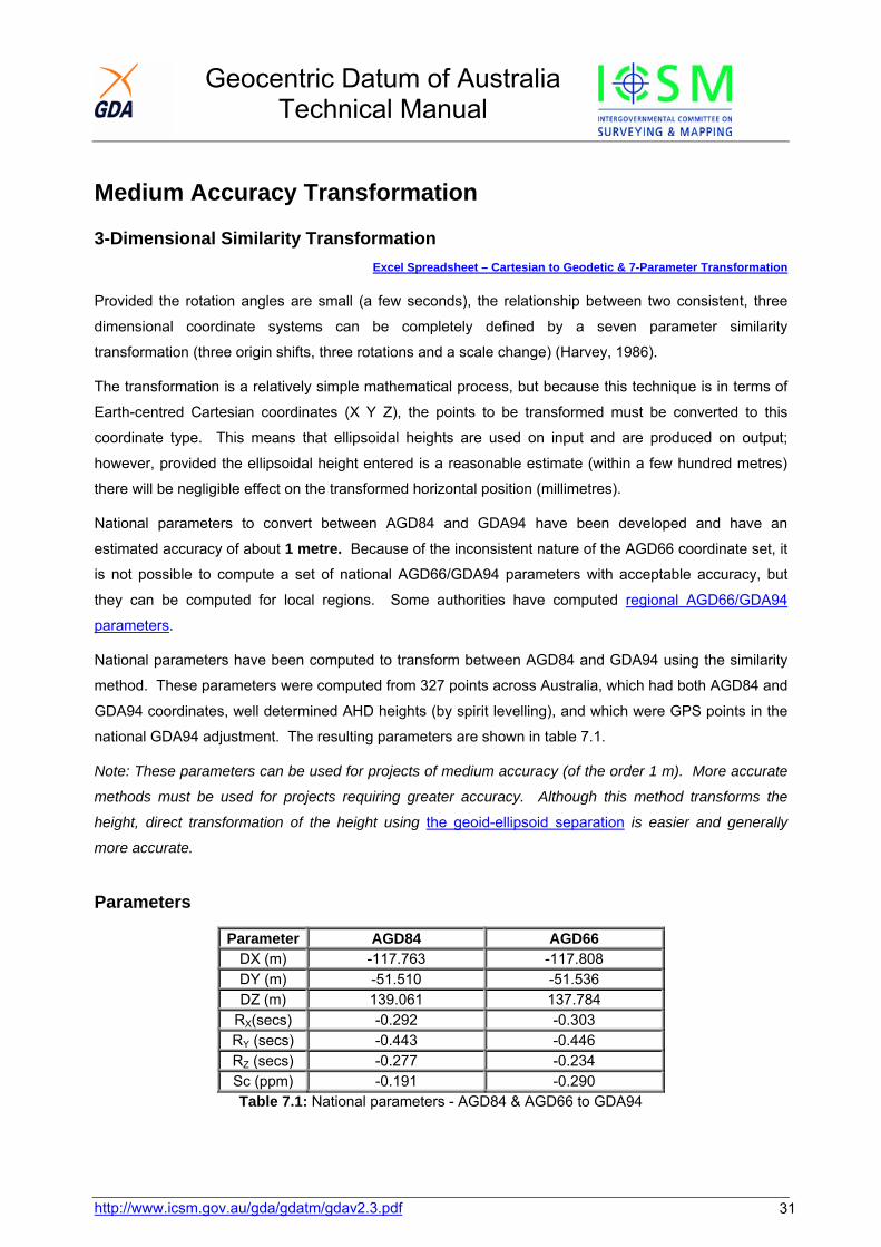
National parameters have been computed to transform between AGD84 and GDA94 using the similarity
method. These parameters were computed from 327 points across Australia, which had both AGD84 and
GDA94 coordinates, well determined AHD heights (by spirit levelling), and which were GPS points in the
national GDA94 adjustment. The resulting parameters are shown in table 7.1.
Note: These parameters can be used for projects of medium accuracy (of the order 1 m). More accurate
methods must be used for projects requiring greater accuracy. Although this method transforms the
height, direct transformation of the height using the geoid-ellipsoid separation is easier and generally
more accurate.
Parameters
Parameter AGD84 AGD66 DX (m) -117.763 -117.808 DY (m) -51.510 -51.536 DZ (m) 139.061 137.784
RX(secs) -0.292 -0.303 RY (secs) -0.443 -0.446 RZ (secs) -0.277 -0.234 Sc (ppm) -0.191 -0.290 Table 7.1: National parameters - AGD84 & AGD66 to GDA94
Geocentric Datum of Australia Technical Manual
The AGD84 parameters were tested using points additional to the initial 327, which had both AGD84 and
GDA94 coordinates. A summary of these tests is shown in table 7.2. The AGD66 parameters were
developed as first step in the production of the national transformation grid and used 9,761 common
points.
Average (m) Std. Dev. (m) Max (m) Min (m) Latitude -0.10 0.38 1.03 -1.48 Longitude -0.08 0.38 1.14 -2.50 Ellip. Ht. 0.14 0.37 0.95 -0.66
Table 7.2: AGD84 <->GDA94 parameters - residuals from 1571 points (lat/long) and 65 points (ellip. ht.)
Formulae
Once the positions have been converted to Earth-centred Cartesian coordinates, the similarity
transformation is performed by a simple matrix operation:
'''
zyx
=
ZzYRScyXx
Δ++Δ
Δ)10-*1( 6
Where R is the combined matrix of rotations about the X, Y and Z axes, in that order, i.e.
R = Rx Ry Rz
In its full form this combined rotation matrix is:
CosRxCosRySinRxCosRzSinRzCosRxSinRySinRxSinRzCosRzCosRxSinRySinRxCosRyCosRxCosRzSinRzSinRxSinRyCosRxSinRzCosRzSinRxSinRy
SinRyCosRySinRzCosRyCosRx
−++−
−
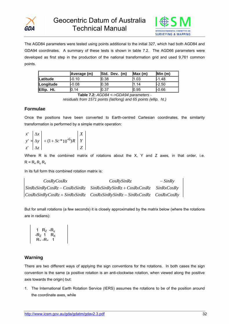
But for small rotations (a few seconds) it is closely approximated by the matrix below (where the rotations
are in radians):
1 RZ -Ry-RZ 1 RXRY -RX 1
Warning
There are two different ways of applying the sign conventions for the rotations. In both cases the sign
convention is the same (a positive rotation is an anti-clockwise rotation, when viewed along the positive
axis towards the origin) but:
1. The International Earth Rotation Service (IERS) assumes the rotations to be of the position around
the coordinate axes, while
http://www.icsm.gov.au/gda/gdatm/gdav2.3.pdf 32
Geocentric Datum of Australia Technical Manual
http://www.icsm.gov.au/gda/gdatm/gdav2.3.pdf 33
2. The method historically used in Australia assumes the rotations to be of the coordinate axes.
The only difference in the formula is a change in the signs of the angles in the rotation matrix. If the sign
of the rotation parameters and the formulae used are consistent the correct results will be obtained. The
only way to be absolutely sure which method or parameters are required is to test them using a known
input and output for a set of parameters as shown in Table 7.3. If necessary the situation can be rectified
by simply changing the sign of the rotation parameters.
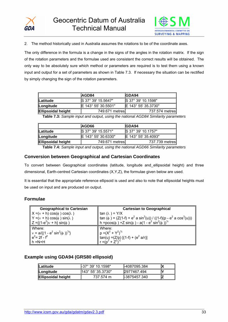
AGD84 GDA94 Latitude S 37° 39' 15.5647" S 37° 39' 10.1598" Longitude E 143° 55' 30.5501" E 143° 55' 35.3730" Ellipsoidal height 749.671 metres 737.574 metres
Table 7.3: Sample input and output, using the national AGD84 Similarity parameters
AGD66 GDA94 Latitude S 37° 39' 15.5571" S 37° 39' 10.1757" Longitude E 143° 55' 30.6330" E 143° 55' 35.4093" Ellipsoidal height 749.671 metres 737.739 metres
Table 7.4: Sample input and output, using the national AGD66 Similarity parameters
Conversion between Geographical and Cartesian Coordinates
To convert between Geographical coordinates (latitude, longitude and ellipsoidal height) and three
dimensional, Earth-centred Cartesian coordinates (X,Y,Z), the formulae given below are used.
It is essential that the appropriate reference ellipsoid is used and also to note that ellipsoidal heights must
be used on input and are produced on output.
Formulae
Geographical to Cartesian X =(ν + h) cos(φ ) cos(λ ) Y =(ν + h) cos(φ ) sin(λ ) Z ={(1-e2)ν + h} sin(φ )
Cartesian to Geographical tan (λ ) = Y/X tan (φ ) = (Z(1-f) + e2 a sin3(u)) / ((1-f)(p - e2 a cos3(u))) h =pcos(φ ) +Z sin(φ ) - a(1 - e2 sin2(φ ))½
Where: ν = a/{(1 - e2 sin2(φ ))½} e2= 2f - f2
h =N+H
Where: p =(X2 + Y2)½
tan(u) =(Z/p) [(1-f) + (e2 a/r)] r =(p2 + Z2)½
Example using GDA94 (GRS80 ellipsoid)
Latitude -37° 39' 10.1598" -4087095.384 X Longitude 143° 55' 35.3730" 2977467.494 Y Ellipsoidal height 737.574 m -3875457.340 Z

Geocentric Datum of Australia Technical Manual
http://www.icsm.gov.au/gda/gdatm/gdav2.3.pdf 34
Regional Transformation Parameters from AGD66 to GDA94
Although it is possible to compute national similarity transformation parameters between AGD84 &
GDA94, AGD66/GDA94 similarity transformation parameters can only be accurately computed for smaller
areas where AGD66 is more consistent. This was done as a first step in the development of the
jurisdiction transformation grids and where the more accurate methods are not appropriate, these
parameters may be used.
The parameters shown are only valid for transformation between AGD66 and GDA94 for the area
indicated. They have an accuracy of only about 1 metre and the transformation grid method is preferred if
at all possible.
Parameter A.C.T. Tasmania VictoriaNSW
Northern Territory
DX (m) -129.193 -120.271 -119.353 -124.133 DY (m) -41.212 -64.543 -48.301 -42.003 DZ (m) 130.730 161.632 139.484 137.400 RX (secs) -0.246 -0.217 -0.415 0.008 RY (secs) -0.374 0.067 -0.260 -0.557 RZ (secs) -0.329 0.129 -0.437 -0.178 Sc (ppm) -2.955 2.499 -0.613 -1.854
Table 7.5: Regional similarity transformation parameters - AGD66 to GDA94.
AGD66 GDA94 Latitude S 35° 18' 18.0000" S 35° 18' 12.3911" Longitude E 149° 08' 18.0000" E 149° 08' 22.3382" Ellipsoidal height
600.000 metres 601.632 metres
Table 7.6: Sample input and output, using the A.C.T. Similarity parameters
AGD66 GDA94 Latitude S 42° 53' 03.0000" S 42° 52' 57.6165" Longitude E 147° 19' 19.0000" E 147° 19' 23.9274" Ellipsoidal height
100.000 metres 77.163 metres
Table 7.7: Sample input and output, using the Tasmanian Similarity parameters
AGD66 GDA94 Latitude S 33° 25' 25.12340" S 33° 25' 19.48962" Longitude E 149° 34' 34.34560" E 149° 34' 38.58555" Ellipsoidal height
603.345 metres 610.873 metres
Table 7.8: Sample input and output, using the Victoria/NSW Similarity parameters

Geocentric Datum of Australia Technical Manual
http://www.icsm.gov.au/gda/gdatm/gdav2.3.pdf 35
Low Accuracy Transformation
Molodensky's Formulae Excel Spreadsheet – Molodensky’s Transformation
Molodensky's transformation method uses an average origin shift (at the centre of the earth) and the
change in the parameters of the two ellipsoids. This method is often used in hand-held GPS receivers
with the old parameters published by United States National Imagery and Mapping Agency (NIMA) in their
Technical Report 8350.2. These DMA parameters are now superseded by AGD66/84<->GDA94
parameters which have an estimated accuracy of about 5 metres:
Transformation from AGD66 or AGD84 to GDA94
Abridged Molodensky Formulae & Parameters
The United States Defense Mapping Agency previously published parameters for use with Molodensky's
formulae, to convert between either AGD66 or AGD84 and WGS84 (DMA, 1987). As for most practical
purposes WGS84 is the same as GDA94, the same formula may continue to be used, but improved
parameters are now available to convert between either AGD66 or AGD84 and GDA94 (AUSLIG,1997).
It should be noted that these formulae require ellipsoidal height on input and give ellipsoidal height on
output; however, the height component may be ignored if not required.
Note: This transformation method should only be used for low accuracy projects (accuracy no better than
5m). Other methods are available for higher accuracy projects.
The AGD66/GDA94 parameters were derived from 161 points across Australia, which had both AGD66
and GDA94 coordinates, each of which also had a spirit levelled height. The AGD84/GDA94 parameters
were similarly derived using 327 common points. These parameters are shown in table 7.9.
Parameters
AGD66 to GDA94 AGD84 to GDA94 A 6378160 m 6378160 m 1/f 298.25 298.25 DX (m) -127.8 -128.5 DY (m) -52.3 -53.0 DZ (m) 152.9 153.4 Da (m) -23 -23 Df -0.00000008119 -0.00000008119
Table 7.9: Parameters - AGD66 & AGD84 to GDA94
These parameters were tested using additional points with both AGD and GDA94 positions. A summary
of these tests is shown in tables 7.10 and 7.11.
Geocentric Datum of Australia Technical Manual
http://www.icsm.gov.au/gda/gdatm/gdav2.3.pdf 36
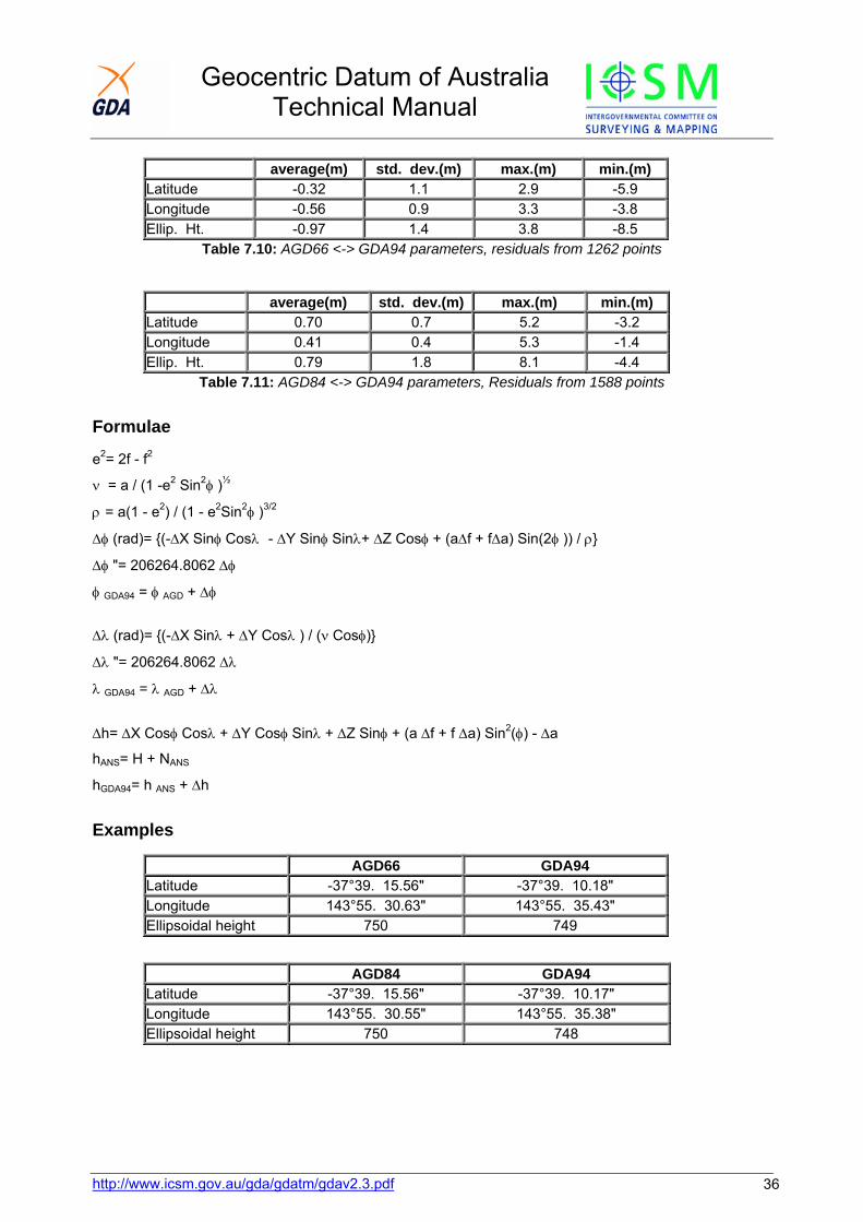
average(m) std. dev.(m) max.(m) min.(m) Latitude -0.32 1.1 2.9 -5.9 Longitude -0.56 0.9 3.3 -3.8 Ellip. Ht. -0.97 1.4 3.8 -8.5
Table 7.10: AGD66 <-> GDA94 parameters, residuals from 1262 points
average(m) std. dev.(m) max.(m) min.(m) Latitude 0.70 0.7 5.2 -3.2 Longitude 0.41 0.4 5.3 -1.4 Ellip. Ht. 0.79 1.8 8.1 -4.4
Table 7.11: AGD84 <-> GDA94 parameters, Residuals from 1588 points
Formulae
e2= 2f - f2
ν = a / (1 -e2 Sin2φ )½
ρ = a(1 - e2) / (1 - e2Sin2φ )3/2
Δφ (rad)= {(-ΔX Sinφ Cosλ - ΔY Sinφ Sinλ+ ΔZ Cosφ + (aΔf + fΔa) Sin(2φ )) / ρ}
Δφ "= 206264.8062 Δφ
φ GDA94 = φ AGD + Δφ
Δλ (rad)= {(-ΔX Sinλ + ΔY Cosλ ) / (ν Cosφ)}
Δλ "= 206264.8062 Δλ
λ GDA94 = λ AGD + Δλ
Δh= ΔX Cosφ Cosλ + ΔY Cosφ Sinλ + ΔZ Sinφ + (a Δf + f Δa) Sin2(φ) - Δa
hANS= H + NANS
hGDA94= h ANS + Δh
Examples
AGD66 GDA94 Latitude -37°39. 15.56" -37°39. 10.18" Longitude 143°55. 30.63" 143°55. 35.43" Ellipsoidal height 750 749
AGD84 GDA94 Latitude -37°39. 15.56" -37°39. 10.17" Longitude 143°55. 30.55" 143°55. 35.38" Ellipsoidal height 750 748
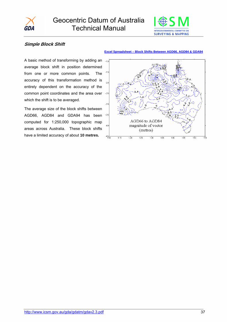
Geocentric Datum of Australia Technical Manual
Simple Block Shift
Excel Spreadsheet – Block Shifts Between AGD66, AGD84 & GDA94
A basic method of transforming by adding an
average block shift in position determined
from one or more common points. The
accuracy of this transformation method is
entirely dependent on the accuracy of the
common point coordinates and the area over
which the shift is to be averaged.
The average size of the block shifts between
AGD66, AGD84 and GDA94 has been
computed for 1:250,000 topographic map
areas across Australia. These block shifts
have a limited accuracy of about 10 metres.
http://www.icsm.gov.au/gda/gdatm/gdav2.3.pdf 37
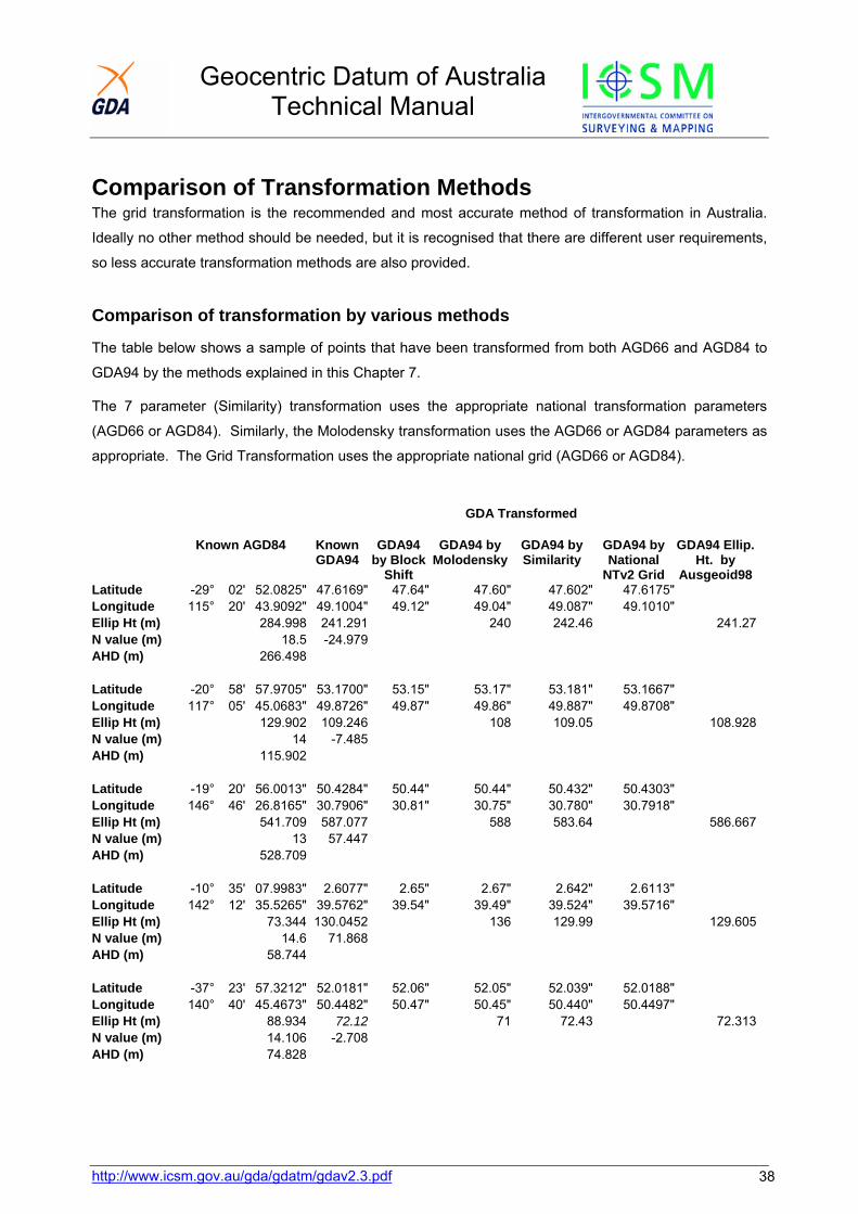
Geocentric Datum of Australia Technical Manual
http://www.icsm.gov.au/gda/gdatm/gdav2.3.pdf 38
Comparison of Transformation Methods The grid transformation is the recommended and most accurate method of transformation in Australia.
Ideally no other method should be needed, but it is recognised that there are different user requirements,
so less accurate transformation methods are also provided.
Comparison of transformation by various methods
The table below shows a sample of points that have been transformed from both AGD66 and AGD84 to
GDA94 by the methods explained in this Chapter 7.
The 7 parameter (Similarity) transformation uses the appropriate national transformation parameters
(AGD66 or AGD84). Similarly, the Molodensky transformation uses the AGD66 or AGD84 parameters as
appropriate. The Grid Transformation uses the appropriate national grid (AGD66 or AGD84).
GDA Transformed
Known AGD84 Known GDA94
GDA94 by Block
Shift
GDA94 by Molodensky
GDA94 by Similarity
GDA94 by National
NTv2 Grid
GDA94 Ellip. Ht. by
Ausgeoid98Latitude -29° 02' 52.0825" 47.6169" 47.64" 47.60" 47.602" 47.6175" Longitude 115° 20' 43.9092" 49.1004" 49.12" 49.04" 49.087" 49.1010" Ellip Ht (m) 284.998 241.291 240 242.46 241.27N value (m) 18.5 -24.979 AHD (m) 266.498 Latitude -20° 58' 57.9705" 53.1700" 53.15" 53.17" 53.181" 53.1667" Longitude 117° 05' 45.0683" 49.8726" 49.87" 49.86" 49.887" 49.8708" Ellip Ht (m) 129.902 109.246 108 109.05 108.928N value (m) 14 -7.485 AHD (m) 115.902 Latitude -19° 20' 56.0013" 50.4284" 50.44" 50.44" 50.432" 50.4303" Longitude 146° 46' 26.8165" 30.7906" 30.81" 30.75" 30.780" 30.7918" Ellip Ht (m) 541.709 587.077 588 583.64 586.667N value (m) 13 57.447 AHD (m) 528.709 Latitude -10° 35' 07.9983" 2.6077" 2.65" 2.67" 2.642" 2.6113" Longitude 142° 12' 35.5265" 39.5762" 39.54" 39.49" 39.524" 39.5716" Ellip Ht (m) 73.344 130.0452 136 129.99 129.605N value (m) 14.6 71.868 AHD (m) 58.744 Latitude -37° 23' 57.3212" 52.0181" 52.06" 52.05" 52.039" 52.0188" Longitude 140° 40' 45.4673" 50.4482" 50.47" 50.45" 50.440" 50.4497" Ellip Ht (m) 88.934 72.12 71 72.43 72.313N value (m) 14.106 -2.708 AHD (m) 74.828
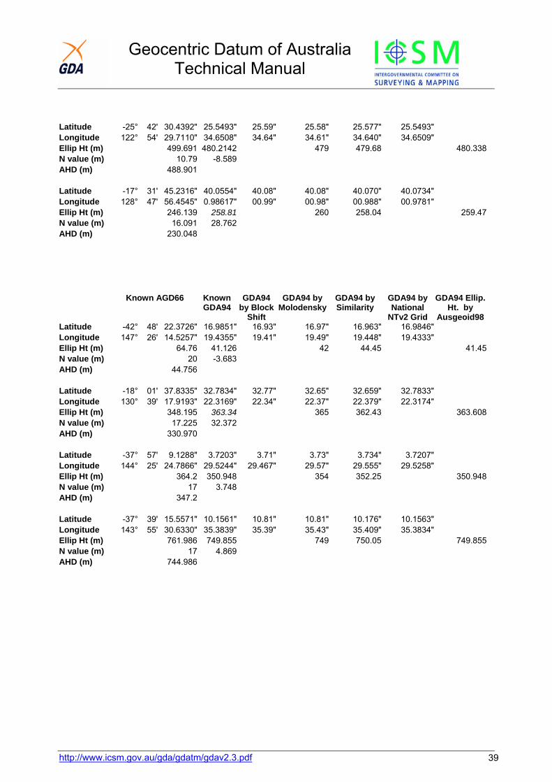
Geocentric Datum of Australia Technical Manual
http://www.icsm.gov.au/gda/gdatm/gdav2.3.pdf 39
Latitude -25° 42' 30.4392" 25.5493" 25.59" 25.58" 25.577" 25.5493" Longitude 122° 54' 29.7110" 34.6508" 34.64" 34.61" 34.640" 34.6509" Ellip Ht (m) 499.691 480.2142 479 479.68 480.338N value (m) 10.79 -8.589 AHD (m) 488.901 Latitude -17° 31' 45.2316" 40.0554" 40.08" 40.08" 40.070" 40.0734" Longitude 128° 47' 56.4545" 0.98617" 00.99" 00.98" 00.988" 00.9781" Ellip Ht (m) 246.139 258.81 260 258.04 259.47N value (m) 16.091 28.762 AHD (m) 230.048
Known AGD66 Known GDA94
GDA94 by Block
Shift
GDA94 by Molodensky
GDA94 by Similarity
GDA94 by National
NTv2 Grid
GDA94 Ellip. Ht. by
Ausgeoid98Latitude -42° 48' 22.3726" 16.9851" 16.93" 16.97" 16.963" 16.9846"Longitude 147° 26' 14.5257" 19.4355" 19.41" 19.49" 19.448" 19.4333" Ellip Ht (m) 64.76 41.126 42 44.45 41.45N value (m) 20 -3.683 AHD (m) 44.756 Latitude -18° 01' 37.8335" 32.7834" 32.77" 32.65" 32.659" 32.7833" Longitude 130° 39' 17.9193" 22.3169" 22.34" 22.37" 22.379" 22.3174" Ellip Ht (m) 348.195 363.34 365 362.43 363.608N value (m) 17.225 32.372 AHD (m) 330.970 Latitude -37° 57' 9.1288" 3.7203" 3.71" 3.73" 3.734" 3.7207" Longitude 144° 25' 24.7866" 29.5244" 29.467" 29.57" 29.555" 29.5258" Ellip Ht (m) 364.2 350.948 354 352.25 350.948N value (m) 17 3.748 AHD (m) 347.2 Latitude -37° 39' 15.5571" 10.1561" 10.81" 10.81" 10.176" 10.1563" Longitude 143° 55' 30.6330" 35.3839" 35.39" 35.43" 35.409" 35.3834" Ellip Ht (m) 761.986 749.855 749 750.05 749.855N value (m) 17 4.869 AHD (m) 744.986
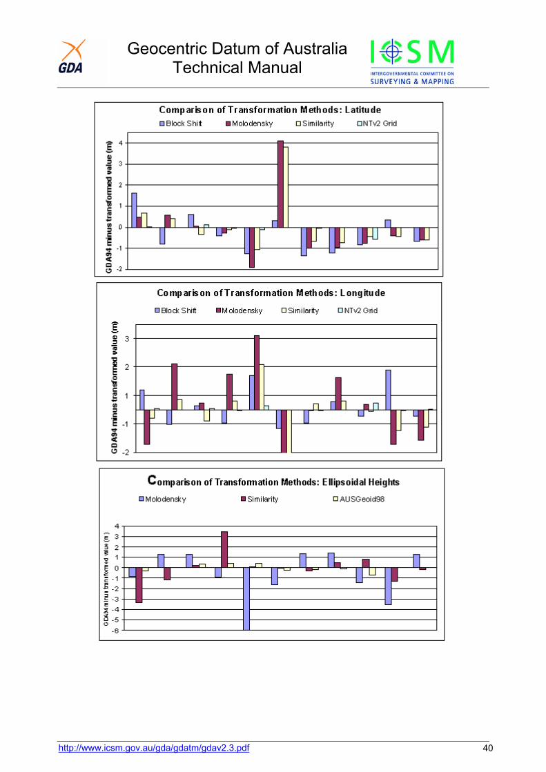
Geocentric Datum of Australia Technical Manual
http://www.icsm.gov.au/gda/gdatm/gdav2.3.pdf 40

Geocentric Datum of Australia Technical Manual
http://www.icsm.gov.au/gda/gdatm/gdav2.3.pdf 41
Chapter 8 The Australian Height Datum (AHD) The AHD Basic Network and Tide Gauges Although the adoption of GDA means that (ITRF92) ellipsoidal heights are available at the AFN and ANN
sites, and at other sites where these ellipsoidal heights have been carried by GPS, the Australian Height
Datum (AHD) remains as the official height datum for Australia. Ellipsoidal heights obtained from GPS
can be converted to approximate AHD using geoid-ellipsoid separations.
Background On 5 May 1971 the then Division of National Mapping, on behalf of the National Mapping Council of
Australia, carried out a simultaneous adjustment of 97,230 kilometres of two-way levelling. Mean sea
level for 1966-1968 was assigned the value of zero on the Australian Height Datum at thirty tide gauges
around the coast of the Australian continent.
The resulting datum surface, with minor modifications in two metropolitan areas, has been termed the
Australian Height Datum (AHD) and was adopted by the National Mapping Council at its twenty-ninth
meeting in May 1971 as the datum to which all vertical control for mapping is to be referred. The datum
surface is that which passes through mean sea level at the thirty tide gauges and through points at zero
AHD height vertically below the other basic junction points.
The determination of the AHD was documented in Division of National Mapping Technical Report No. 12
(Roelse, 1975).
Basic and Supplementary Levelling Two-way levelling of third order accuracy or better, used in the original adjustment of 5 May 1971 which
formed the AHD, is called "Basic levelling". Levelling subsequently adjusted to the AHD is called
"Supplementary levelling".
Tasmania The levelling network in Tasmania was adjusted on 17 October 1983 to re-establish heights on the
Australian Height Datum (Tasmania). This network, which consists of seventy-two sections between fifty-
seven junction points is based on mean sea level for 1972 at the tide gauges at Hobart and Burnie. Mean
sea level at both Hobart and Burnie was assigned the value of zero on the AHD (Tasmania).

Geocentric Datum of Australia Technical Manual
http://www.icsm.gov.au/gda/gdatm/gdav2.3.pdf 42
Islands If the levels on islands closely adjacent to the Australian mainland are observed to standard third order
accuracy, and are referred to mean sea level at a satisfactory tide gauge, they are deemed to be part of
the Australian Height Datum.
AHD, Mean Sea Level and the Geoid The AHD is an imperfect realisation of mean sea level because some of the tide gauges used for its
definition were not well sited; the mean sea level determination was for a limited period and a particular
epoch and no allowance was made for sea surface topography. The difference between AHD and mean
sea level, which may be of the order of several decimetres (Mitchell, 1990), is not significant for
conventional propagation of AHD, which is relative to existing AHD bench marks, but may be important if
connecting AHD to a recent determination of mean sea level.
Although the geoid is often equated to mean sea level, it may actually differ from it by the order of a
metre, largely due to sea surface topography (Bomford, 1980, p250).
With improvements in geoid models and GPS heighting, the difference between these three surfaces may
become apparent, particularly over large areas, or in areas where there are rapid changes in the slope of
the geoid.

Geocentric Datum of Australia Technical Manual
Chapter 9 The Australian National Geoid The geoid is a surface of equal potential that is approximated by mean sea level. However, heights
derived from GPS are relative to the GPS reference ellipsoid (WGS84/GRS80). The separation between
the geoid and an ellipsoid is known as the geoid-ellipsoid separation (N value).
Geoid-ellipsoid Separations If N values in terms of a geocentric datum are used
to reduce observed GPS ellipsoidal heights, the
result will approximate an AHD height (typically
within +/-0.5m). The discrepancy between such a
derived AHD value and a known AHD value may be
due to uncertainty in the observed ellipsoidal height
(GPS), the geoid-ellipsoid separation, or the known
AHD value. However, appropriate GPS
observations and post-processing techniques now make it possible to obtain ellipsoidal heights with an
accuracy of a few centimetres. Therefore, in such a case, most of any discrepancy is likely to be due to
uncertainty in the AHD value and the fact that the geoid does not coincide with the AHD. These
discrepancies are minimised by applying the N values differentially, rather than in an absolute sense (see
below). Recent studies have confirmed that the geoid and AHD are not coincident over Australia, with a
north south trend of about a metre. Future versions of AUSGeoid will include the AHD – geoid difference
so that it will produce AHD values.
When using GPS to derive heights, it is strongly recommended that the ellipsoidal heights are archived.
This allows the derived orthometric height to be traced and if necessary improved, as improved geoid
models become available. Because N values are relative to a specific ellipsoid, care must be taken to
use N values that refer to the correct ellipsoid.
H=h-N Where: H = height above the geoid h = height above the ellipsoid N = Geoid-ellipsoid separation (N value) If the geoid is above the ellipsoid, N is positive If the geoid is below the ellipsoid, N is negative
Δ H = Δh - ΔN where: ΔH is the difference in height above the geoid Δh is the difference in ellipsoidal height, and ΔN is the difference in geoid-ellipsoid separation
http://www.icsm.gov.au/gda/gdatm/gdav2.3.pdf 43
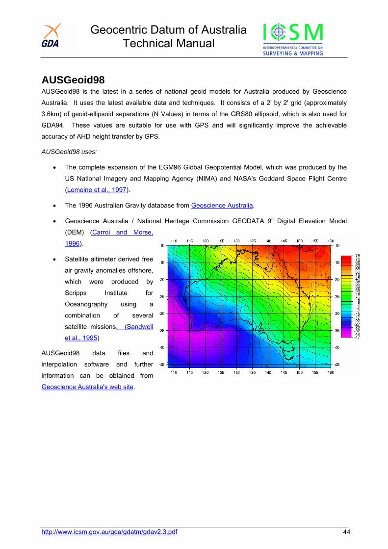
Geocentric Datum of Australia Technical Manual
AUSGeoid98 AUSGeoid98 is the latest in a series of national geoid models for Australia produced by Geoscience
Australia. It uses the latest available data and techniques. It consists of a 2' by 2' grid (approximately
3.6km) of geoid-ellipsoid separations (N Values) in terms of the GRS80 ellipsoid, which is also used for
GDA94. These values are suitable for use with GPS and will significantly improve the achievable
accuracy of AHD height transfer by GPS.
AUSGeoid98 uses:
• The complete expansion of the EGM96 Global Geopotential Model, which was produced by the
US National Imagery and Mapping Agency (NIMA) and NASA's Goddard Space Flight Centre
(Lemoine et al., 1997).
• The 1996 Australian Gravity database from Geoscience Australia.
• Geoscience Australia / National Heritage Commission GEODATA 9" Digital Elevation Model
(DEM) (Carrol and Morse,
1996).
• Satellite altimeter derived free
air gravity anomalies offshore,
which were produced by
Scripps Institute for
Oceanography using a
combination of several
satellite missions. (Sandwell
et al., 1995)
AUSGeoid98 data files and
interpolation software and further
information can be obtained from
Geoscience Australia's web site.
http://www.icsm.gov.au/gda/gdatm/gdav2.3.pdf 44

Geocentric Datum of Australia Technical Manual
http://www.icsm.gov.au/gda/gdatm/gdav2.3.pdf 45
Chapter 10 Test Data GDA94 and MGA94 (zone 55) values
Buninyong Flinders Peak Latitude (φ ) S37° 39' 10.15611" S37° 57' 03.72030" Longitude (λ ) E143° 55' 35.38393" E144° 25' 29.52442" AHD (H) 744.986 347.200 NAUSGeoid98 4.869 3.748 Ellipsoidal height (h) 749.855 350.948 Easting 228,854.052 273,741.297 Northing 5,828,259.038 5,796,489.777 X -4,087,103.458 -4,096,088.424 Y 2,977,473.0435 2,929,823.0843 Z -3,875,464.7525 -3,901,375.4540 Azimuth (α ) 127° 10' 25.07" 306° 52' 05.37" Grid convergence (γ ) -1° 52' 43.22" -1° 35' 03.65" Grid bearing (β ) 125° 17' 41.86" 305° 17' 01.72" Arc to chord (δ ) -20.67" +19.47" Plane bearing (θ ) 125° 17' 21.18" 305° 17' 21.18" Point scale factor (k) 1.000 50567 1.000 23056 Meridian distance (m) -4,173,410.326 -4,205,192.300 Rho (ρ ) 6359253.8294 6359576.5731 Nu (ν ) 6386118.6742 6386226.7080 Ellipsoidal distance (s) 54,972.271 Line scale factor (K) 1.000 36397 Grid (& plane) distance (L) 54,992.279 Meridian convergence (Δ α ) 18' 19.70" Line curvature (Δ β ) 40.14"

Geocentric Datum of Australia Technical Manual
Geocentric Datum of Australia Technical Manual
Traverse Diagram
http://www.icsm.gov.au/gda/gdatm/gdav2.3.pdf http://www.icsm.gov.au/gda/gdatm/gdav2.3.pdf 46 46
Geocentric Datum of Australia Technical Manual
http://www.icsm.gov.au/gda/gdatm/gdav2.3.pdf 47
Chapter 11 Bibliography A.H.Q. Survey Coy., (1942). "Tables for the Computation of Geographic Positions and
Rectangular Co-ordinates (Transverse Mercator projection) -based on Clarke 1858 figure." Compiled by A.H.Q. SurveyCoy., by Authority of Director of Survey, 1942.
Allman, J.S. & Veenstra, C. (1984). "Geodetic Model of Australia", Division of National MappingTechnical Report 33.
AUSLIG (1997) Internal Report to ICSM, November 1997
Bomford G. (1980) "Geodesy", 4th edition, Clarendon Press, Oxford.
Bomford, A.G. (1967) "The Geodetic Adjustment of Australia, 1963-1966", SurveyReview, No. 144, Vol XIX, 1967, pp57-58.
Boucher C., Altamimi Z., Duhem L. (1993)
"ITRF and its associated velocity field", IERS Technical Note15, Central Bureau of IERS, October 1993.
Boucher C., Altamimi Z., Duhem L. (1994)
"Results and analysis of the ITRF93", IERS Technical Note18, Central Bureau of IERS, October 1994.
Bowring, B. R. (1985) "The accuracy of geodetic latitude and height equations",Survey Review. 28 Oct., 202-206
Caroll, D. and Morse, M.P. (1996) "A national digital elevation model for resource andenvironmental management", Cartography, 25(2): 395-405.
Clarke D. (1966) "Plane and Geodetic Surveying", Vol 2, Constable andCompany, London.
Collier P.A., Argeseanu V., Leahy F. (1997)
"Distortion Modelling and the transition to GDA94", TheAustralian Surveyor, Vol. 43, No. 1, March 1998.
Collier P.A. and Steed J. (2001) "Australia's National GDA94 Transformation Grids", 42ndAustralian Surveyors Congress, Brisbane, 25-28 Sept 2001.
Defense Mapping Agency, 1987 "Department of Defense World Geodetic System 1984, itsdefinition and relationships with local geodetic systems", DMATechnical report 8350.2
Featherstone W.E., 1997 "The Importance of Including the Geoid in Terrestrial SurveyData Reduction to the Geocentric Datum of Australia", TheAustralian Surveyor, Vol. 42, No. 1, March 1997.
Grossman (1964) Geodetische Rechnungen und Abbildungen. Page 188.
Harvey B.R., (1986) "Transformation of 3D Coordinates". The Australian Surveyor,June 1986, Vol. 33, No. 2, pp 105-125
Jordan-Eggert. (1941) "Handbuch der Vermessungskunde." Volume III, second half-volume, section 38.
Geocentric Datum of Australia Technical Manual
http://www.icsm.gov.au/gda/gdatm/gdav2.3.pdf 48
Lemoine, F.G., Smith, D.E., Smith, R., Kunz, L., Pavlis, N.K., Klosko, S.M., Chinn, D.S., Torrence, M.H., Williamson, R.G., Cox, C.M., Rachlin, K.E., Wang, Y.M., Pavlis, E.C., Kenyon, S.C., Salman, R., Trimmer, R., Rapp, R.H., Nerem, R.S. (1997)
"The development of the NASA GSFC and DMA jointgeopotential model", in: Segawa, J., Fujimoto, H., Okubo, S.,(eds) Gravity, Geoid and Marine Geodesy, Springer, Berlin,Germany, 461-469.
Lines J.D., (1992) "Australia on Paper, The Story of Australian Mapping",Fortune Publications, Box Hill Victoria
Malays S., & Slater J., (1994) "Maintenance and enhacement of the World Geodetic System1984", Proceedings of ION GPS-94, Salt lake City, Sept.1994
Malays S., Slater J., Smith R.W., Kunz L.E., Kenyon S.C. (1997)
"Refinements to the World Geodetic System 1984",Proceedings of the 10th International Technical meeting of theSatellite Division of the Institute of Navigation, September 16-19, 1997, Kansas City, Missouri, USA.
Mitchell H.L. et al (1990) "GPS Heighting and the AHD", Report prepared for the GPSUsers group, by the GPS Heighting study Group.
Morgan et al. (1996) "A zero order GPS network for the Australian region",University of NSW, School of Geomatic Engineering, UnisurvReport S-46, 1996.
National Mapping Council of Australia (1976)
"Report on Work Completed During the period 1945-1975".NMP/75/014
National Mapping Council of Australia (1986)
"The Australian Geodetic Datum Technical Manual" NationalMapping Council Special Publication 10.
Rainsford H.F. (1955) "Long Geodesics on the ellipsoid", Bulletin Geodesique, No.37, September 1955.
Redfearn, J.C.B. (1948) "Transverse Mercator Formulae", Empire Survey Review, No.69, 1948
Roelse A., Granger H.W., Graham J.(1975)
"The adjustment of the Australian levelling survey 1970-1971",National Mapping Technical Report No. 12, 2nd edition.
Rueger, J M (1996) "Electronic Distance Measurment - An Introduction", 4thedition.Springer-Verlag, Berlin-Heidelberg-New York. 1996
Sandwell, D.T., Yale, M.M., Smith, W.H.F. (1995)
"Gravity anomaly profiles from ERS-1, Topex and Geosataltimetry", EOS - Transactions of the American GeophysicalUnion, 76(17): S89.
Seeber G., (1993) "Satellite Geodesy", de Gruyter, New York.
Snyder J.P. (1984) "Map Projections used by the U.S. Geological Survey",United States of America Department of Interior, U.S.Geological Survey Bulletin 1532, 2nd Edition, 1984.

Geocentric Datum of Australia Technical Manual
http://www.icsm.gov.au/gda/gdatm/gdav2.3.pdf 49
Sodano E.M. (1965) "General non-iterative solution of the inverse and directgeodetic problem", Bulletin Geodesique. No. 75, 1965
Soler T., Hothem L.D. (1989) "Important parameters used in Geodetic Transformations",Journal of Surveying Engineering, No. 115.
Steed J.B., Holtznagel S. (1994) "AHD Heights from GPS using Ausgeoid93", The AustralianSurveyor, Vol. 39, No. 1, March 1994.
Steed J.B., Luton G. (2000) "WGS84 and the Geocentric Datum of Australia" Proceedingsof ION GPS-2000, Salt Lake City, Sept 2000.
Steed J.B., (1990) "A practical approach to transformation between commonlyused reference systems", The Australian Surveyor,September 1990, Vol. 35 No. 3
Swift E.R. (1994) "Improved WGS84 coordinates for the DMA and Air ForceGPS tracking sites", Proceedings of ION GPS-94, Salt lakeCity, Sept. 1994
Vincenty T., (1975) "Direct and inverse solutions of geodesics on the ellipsoid withapplication of nested equations", Survey Review XXII, 176,April 1975

Geocentric Datum of Australia Technical Manual
http://www.icsm.gov.au/gda/gdatm/gdav2.3.pdf 50
Chapter 12 Glossary Glossary
Item Symbol Explanation
Semi-major axis a Ellipsoid semi-major axis.
Semi-minor axis b Ellipsoid semi-minor axis. b= a(1-f)
Flattening f The relationship between the semi-major and semi-minor axes of the ellipsoid: (a - b)/a
Inverse flattening 1/f The reciprocal of the ellipsoid flattening. This is the value commonly used when specifying an ellipsoid (e.g. 1/f = 298.257).
Eccentricity squared
e2 (a2 - b2)/a2
Second eccentricity squared
e'2 (a2- b2)/b2
Radius of curvature
ρ Radius of curvature of the ellipsoid in the plane of the meridian.
ν Radius of curvature of the ellipsoid in the prime vertical.
R Geometric mean radius of curvature: (ρ ν )1/2
Rα Radius of curvature at a point, in a given azimuth. It may vary by thousands of metres, depending on the azimuth.
ψ Ratio of the ellipsoidal radii of curvature (ν /ρ )
r2 R2 k02 = ρ ν k0
2
rm2 ρ ν k0
2 at φ mLatitude φ Geodetic latitude, negative south of the equator.
φ 1, φ 2 Geodetic latitude at points 1 and 2 respectively.
φ m Mean latitude: (φ 1 + φ 2)/2
Δ φ Latitude difference: (φ 2 - φ 1)
Foot point latitude φ ’ Latitude for which the meridian distance (m) = N'/ k0. t’, ψ ’, ρ ’, ν ’ are functions of the latitude φ ’.
Longitude λ Geodetic longitude measured from Greenwich, positive eastwards.
λ 1, λ 2 Geodetic longitude at points 1 and 2 respectively.
Δ λ Longitude difference: (λ 2-λ 1)
λ 0 Geodetic longitude of the central meridian
ω Geodetic longitude difference measured from the central meridian, positive eastwards: λ - λ 0
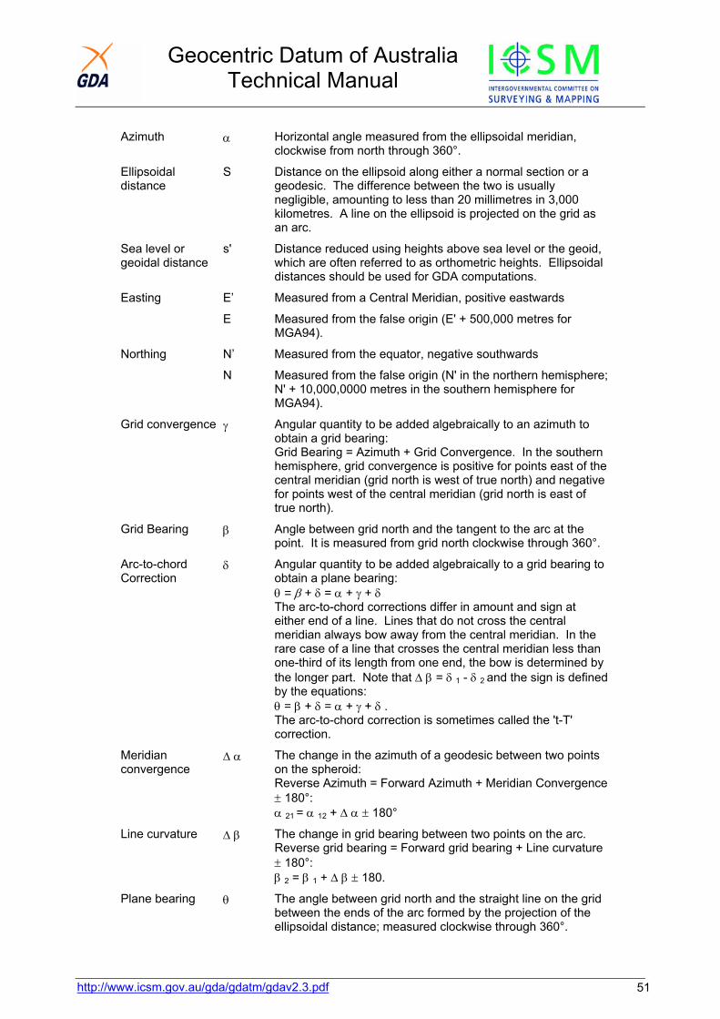
Geocentric Datum of Australia Technical Manual
http://www.icsm.gov.au/gda/gdatm/gdav2.3.pdf 51
Azimuth α Horizontal angle measured from the ellipsoidal meridian, clockwise from north through 360°.
Ellipsoidal distance
S Distance on the ellipsoid along either a normal section or a geodesic. The difference between the two is usually negligible, amounting to less than 20 millimetres in 3,000 kilometres. A line on the ellipsoid is projected on the grid as an arc.
Sea level or geoidal distance
s' Distance reduced using heights above sea level or the geoid, which are often referred to as orthometric heights. Ellipsoidal distances should be used for GDA computations.
Easting E’ Measured from a Central Meridian, positive eastwards
E Measured from the false origin (E' + 500,000 metres for MGA94).
Northing N’ Measured from the equator, negative southwards
N Measured from the false origin (N' in the northern hemisphere; N' + 10,000,0000 metres in the southern hemisphere for MGA94).
Grid convergence γ Angular quantity to be added algebraically to an azimuth to obtain a grid bearing: Grid Bearing = Azimuth + Grid Convergence. In the southern hemisphere, grid convergence is positive for points east of the central meridian (grid north is west of true north) and negative for points west of the central meridian (grid north is east of true north).
Grid Bearing β Angle between grid north and the tangent to the arc at the point. It is measured from grid north clockwise through 360°.
Arc-to-chord Correction
δ Angular quantity to be added algebraically to a grid bearing to obtain a plane bearing: θ = β + δ = α + γ + δ The arc-to-chord corrections differ in amount and sign at either end of a line. Lines that do not cross the central meridian always bow away from the central meridian. In the rare case of a line that crosses the central meridian less than one-third of its length from one end, the bow is determined by the longer part. Note that Δ β = δ 1 - δ 2 and the sign is defined by the equations: θ = β + δ = α + γ + δ . The arc-to-chord correction is sometimes called the 't-T' correction.
Meridian convergence
Δ α The change in the azimuth of a geodesic between two points on the spheroid: Reverse Azimuth = Forward Azimuth + Meridian Convergence ± 180°: α 21 = α 12 + Δ α ± 180°
Line curvature Δ β The change in grid bearing between two points on the arc. Reverse grid bearing = Forward grid bearing + Line curvature ± 180°: β 2 = β 1 + Δ β ± 180.
Plane bearing θ The angle between grid north and the straight line on the grid between the ends of the arc formed by the projection of the ellipsoidal distance; measured clockwise through 360°.

Geocentric Datum of Australia Technical Manual
http://www.icsm.gov.au/gda/gdatm/gdav2.3.pdf 52
Grid distance S The length measured on the grid, along the arc of the projected ellipsoid distance.
Plane distance L The length of the straight line on the grid between the ends of the arc of the projected ellipsoidal distance. The difference in length between the plane distance (L) and the grid distance (S) is nearly always negligible. Using plane bearings and plane distances, the formulae of plane trigonometry hold rigorously: tan θ = Δ E/ Δ N; Δ E = L sin θ ; Δ N = L cos θ .
Meridian distance m True distance from the equator, along the meridian, negative southwards.
G Mean length of an arc of one degree of the meridian.
σ Meridian distance expressed as units G: σ = m/G
Central scale factor
k0 Scale factor on the central meridian ( 0.9996 for MGA94)
Point scale factor k Ratio of an infinitesimal distance at a point on the grid to the corresponding distance on the spheroid: k = dL/ds = dS/ds It is the distinguishing feature of conformal projections, such as the Universal Transverse Mercator used for MGA94, that this ratio is independent of the azimuth of the infinitesimal distance.
Line scale factor K Ratio of a plane distance (L) to the corresponding ellipsoidal distance (s): K = L/s ≈ S/s. The point scale factor will in general vary from point to point along a line on the grid,
Ellipsoidal height h Ellipsoidal Height (h) is the distance of a point above the ellipsoid, measured along the normal from that point to the surface of the ellipsoid used.
Δh Change in ellipsoidal height (m)
Height above the geoid
H Height of a point above the geoid measured along the normal from that point to the surface of the geoid. It is also referred to as the orthometric height.
Geoid-ellipsoid separation
N Distance from the surface of the ellipsoid used, to the surface of the geoid measured along the normal to this ellipsoid. This separation is positive if the geoid is above the ellipsoid and negative if the geoid is below the ellipsoid. h - H = geoid ellipsoid separation.
Earth-centred Cartesian coordinates.
X, Y, Z A three dimensional coordinate system which has its origin at (or near) the centre of the earth. These coordinates are commonly used for satellite derived positions (e.g. GPS) and although they relate to a specific reference system they are independent of any ellipsoid. The positive Z axis coincides with (or is parallel to) the earth’s mean axis of rotation and the X and Y axes are chosen to obtain a right-handed coordinate system; for convenience it can be assumed that the positive arm of the X axis passes through the Greenwich meridian.

Geocentric Datum of Australia Technical Manual
http://www.icsm.gov.au/gda/gdatm/gdav2.3.pdf 53
Transformation parameters
Δa Change in ellipsoid semi-major axis (e.g. from ANS to GRS80) (m)
Δf change in ellipsoid flattening (e.g. from ANS to GRS80)
ΔX origin shift along the X axis (m)
ΔY origin shift along the Y axis (m)
ΔZ origin shift along the Z axis (m)
Rx Rotation of the X axis (radians); positive when anti-clockwise as viewed from the positive end of the axis looking towards the origin.
Ry Rotation of the Y axis (radians); positive when anti-clockwise as viewed from the positive end of the axis looking towards the origin.
Rz Rotation of the Z axis (radians); positive when anti-clockwise as viewed from the positive end of the axis looking towards the origin.
Sc Change in scale (parts per million - ppm).

Geocentric Datum of Australia Technical Manual
Glossary Diagrams
MGA cross section
Latitude Longitude
Semi-major and Semi-Minor axis
http://www.icsm.gov.au/gda/gdatm/gdav2.3.pdf 54
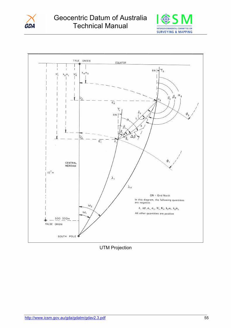
Geocentric Datum of Australia Technical Manual
UTM Projection
http://www.icsm.gov.au/gda/gdatm/gdav2.3.pdf 55
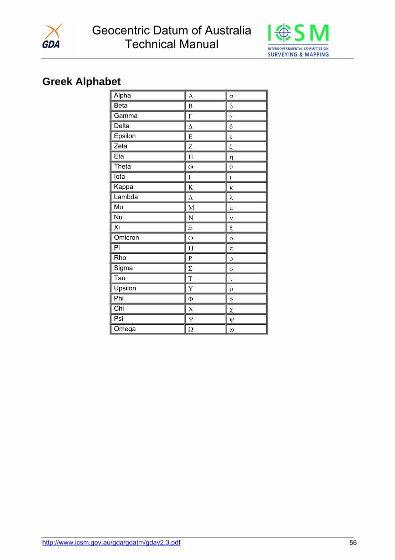
Geocentric Datum of Australia Technical Manual
http://www.icsm.gov.au/gda/gdatm/gdav2.3.pdf 56
Greek Alphabet Alpha Α α Beta Β β Gamma Γ γ Delta Δ δ Epsilon Ε ε Zeta Ζ ζ Eta Η η Theta Θ θ Iota Ι ι Kappa Κ κ Lambda Λ λ Mu Μ μ Nu Ν ν Xi Ξ ξ Omicron Ο ο Pi Π π Rho Ρ ρ Sigma Σ σ Tau Τ τ Upsilon Υ υ Phi Φ φ Chi Χ χ Psi Ψ ψ Omega Ω ω

Geocentric Datum of Australia Technical Manual
http://www.icsm.gov.au/gda/gdatm/gdav2.3.pdf 57
Chapter 13 Revision List Date Revision
Version 2.3 (1)
July 2009 Typographical, layout and hyperlink amendments.
Version 2.3
February 2006 Chapter 1 - Modified statement re GDA and ITRF Chapter 7 - modified redirection to ITRF to GDA information Chapter 9 – AUSGeoid to AHD explained in greater detail
February 2003 Chapter 7 - Corrected Error from 0ctober 2001 rewrite, Page 7-32 Combined Rotation Matrix.
Version 2.2
February 2002 Converted to PDF format 4 October 2001 Chapter 7 - Comparison of transformation methods - updated to use
national NTv2 grids and national AGD66 similarity parameters. 4 October 2001 Chapter 9 - More detail added on the relationship between AHD & the
geoid 4 October 2001 Bibliography - added paper by Collier & Steed on transformation grids 4 October 2001 Chapter 1 amended to include references to ITRF/GDA94 transformation. 4 October 2001 Chapter 7 - Similarity transformation. AGD66 national parameters added. 4 October 2001 Chapter 7 amended to include the National Transformation Grids and test
data for them.
Version 2.1
1 May 2001 Typographical and layout amendments. 1 January 2001 Chapter 7 Updated Grid File Transformation data 1 August 2000 Chapter 7 - now includes additional details on "High Accuracy
Transformations Grids" 1 August 2000 Chapter 7 - Comparison of Transformation Methods -updated table
includes "transformation grids" 1 August 2000 Chapter 7 - Update of Regional Transformation Parameters
Geocentric Datum of Australia Technical Manual
http://www.icsm.gov.au/gda/gdatm/gdav2.3.pdf 58
1 August 2000 Chapter 7 - New Transformation comparison diagram. 1 August 2000 Chapter 3 -Change of title from Reduction of Measured Angles to
Reduction of Measured Directions. 1 August 2000 Chapter 3 - Reduction of Measured Angles - minor change to symbology 1 August 2000 Chapter 8 - AHD network new "PDF" diagram 1 August 2000 Chapter 5 - Changes to layout of "Grid to Geographical" formulae. 1 August 2000 Bibliography - added reference to Rueger J M. 1 August 2000 Chapter 1 - added reference to Bomford 1 August 2000 Chapter 7 - Fixed link to NIMA
Version 2.0
31 August 1999 Conversion to PDF
Version 1.1 (1)
1 August 1999 Chapter 1
- correction - added under Clarke "Inverse Flattening (1/f)" 1 August 1999 Chapter 7
- updated Tasmanian Regional Transformation Parameters. 1 August 1999 Chapter 7
- minor addition to Redfearn and Vincenty spreadsheets. - correction to south latitude values - only degrees have negative sign - not minutes and seconds
1 August 1999 Chapter 7
- update - Progress on High Accuracy Transformations
Version 1.1
11 May 1999 Chapter 4
- Vincenty's formulae replaces Sodano's formulae (Vincenty's formulae more rigorous, but the difference is only of the order of 0.03 ppm).
11 May 1999 Chapter 1
- AGD added to "other coordinates". 11 May 1999 Chapter 3
- spreadsheet to compute deflections of the vertical and Laplace correction modified to use user input deflections rather than astronomically determined ones.
31 May 1999 Chapter 1 - minor addition to section on AGD84.
Geocentric Datum of Australia Technical Manual
http://www.icsm.gov.au/gda/gdatm/gdav2.3.pdf 59
Version 1.0 (2)
14 December 1998 Contents page - link to microsoft Excel viewer updated. 14 December 1998 Chapter 1
- Minor typographical amendments; - Links to Coordinate history added; - longitude of UTM origin corrected; - definition of the pre-1966 ANG significantly amended.
14 December 1998 Logo in page headers linked to GDA home page logo decription and conditions of use.
14 December 1998 Minor amendment to Foreword. 14 December 1998 Chapter 2 - Figure 2.1 replaced with a clearer version.
14 December 1998 Chapter 3 - height of station Kaputar updated in worked example and spreadsheet.
14 December 1998 Chapter 3 - worked example rearranged for clarity.
14 December 1998 Chapter 5 - cosmetic changes to some formulae; - correction to term2 of point scale factor (Grid to geographical).
14 December 1998 Chapter 6 - Typographical amendments;
Corrections to formulae: - Grid bearing & ellipsoidal distance from MGA94 coords; - MGA94 coords from grid bearing & ellipsoidal distance; - Zone to zone transformation.
14 December 1998 Chapter 7:
- style amendments; - link added to regional AGD66/GDA94 parameters; - major additions to section on high accuracy transformation.
14 December 1998 Chapter 8 - Typographical amendments. 14 December 1998 Chapter 9 - UPdated for AUSGeoid98. 14 December 1998 Molodensky's formulae - Typographical amendments. 14 December 1998 Similarity formulae
- Typographical amendments; - full rotation matrix added; - minor typographical correction
14 December 1998 XYZ Coordinates - link to bibliography corrected 14 December 1998 Transformation comparison - Style correction.
Geocentric Datum of Australia Technical Manual
http://www.icsm.gov.au/gda/gdatm/gdav2.3.pdf 60
14 December 1998 Section added on regional AGD66/GDA94 similarity transformation parameters.
14 December 1998 Glossary:
- Typographical amendments; - derivation of semi-major axis added; - MGA cross-section diagram replaced with clearer version.
14 December 1998 Bibliography
- references added. 6 April 1999 Bibliography
- reference added (Featherstone 1999).
Version 1.0 (1) 10 June 1998 Chapter 5 - Minor typographical amendments to formulae .
10 June 1998 Bibliography - Remove duplicate reference and minor typographical corrections.
10 June 1998 Chapter 5 - Change reference to "radians" to "degrees", in GRS80 formula for Meridian Distance. Also show first term to 6 decimal places (111132.952547).
15 June 1998 Chapter 4 - Reference to Vincenty's formulae added
15 June 1998 Bibliography- Reference to Vincenty's formulae and Malys & Slater (1994) added
15 June 1998 Contents - minor changes to wording 15 June 1998 Chapters 2,3,8, 9 and Glossary - Minor change to title 15 June 1998 Contents - Minor changes to text style
15 June 1998 Chapter 1 - Minor changes to text style and addition of WGS84(G873) to discussion of WGS84/GDA
15 June 1998 Chapter 4, 6,7,8 & Glossary - Typographical corrections 15 June 1998 Chapter 5 - Corrections to type fonts 15 June 1998 Contents - Feedback form and disclaimer added 24 June 1998 Contents - Link added to Victoria's "Simplified MGA Manual"
Version 1.0 December 1997 Initial Draft - Chapter 7 complete 27 April 1998 Completed draft version 5 May 1998 Minor typographical amendments to most sections 5 May 1998 Addition to Bibliography (Seeber, 1993)
Geocentric Datum of Australia Technical Manual
http://www.icsm.gov.au/gda/gdatm/gdav2.3.pdf 61
5 May 1998 Chapter 1 - information added on ITRF. 25 May 1998 Chapter 5 - Minor typographical amendments.