geoch3
DESCRIPTION
HW geo 3TRANSCRIPT

C O N T E N T S
SEDIMENTOLOGY3.1 INTRODUCTION
3.1.1 General Introduction3.1.2 Definitions3.1.3 Objectives
3.2 CLASSIFICATION OF SEDIMENTARYROCKS
3.3 SEDIMENT TEXTURE3.3.1 Introduction3.3.2 Texture in Granular Sediments3.3.2.1 Grain Size3.3.2.2 Sorting3.3.2.3 Grain Shape3.3.2.4 Fabric3.3.2.5 Grain Morphology and Surface Texture3.3.2.6 Textural Maturity
3.4 SANDS AND SANDSTONES3.5 POROSITY AND PERMEABILITY
3.5.1 Definitions3.5.2 Porosity Types3.5.3 Controls on Porosity and Permeability3.5.3.1 Grain Size3.5.3.2 Sorting3.5.3.3 Grain Shape3.5.3.4 Packing3.5.3.5 Fabric3.5.3.6 Grain Morphology and Surface Texture3.5.3.7 Diagenesis (e.g.Compaction, Cementation)
3.6 TRANSPORT AND DEPOSITION OFSEDIMENTS3.6.1 Physical Processes of Transportation3.6.2 Transport by Fluids3.6.2.1 Bedforms and Sedimentary Structures3.6.2.2 Current-Generated Bedforms and
Sedimentary Structures (water currents)3.6.2.3 Wave-Generated Bedforms and
Sedimentary Structures3.6.2.4 Wind-Generated Bedforms and
Sedimentary Structures3.6.2.5 Sediment Gravity Flows
3.7 OTHER SEDIMENTARY STRUCTURES3.7.1 Introduction3.7.2 Further Discussion of Primary
Sedimentary Structures3.7.3 Secondary Sedimentary Structures3.7.3.1 Erosional sedimentary structures
33Sedimentology
3.7.3.2 Deformational Sedimentary Structures3.7.3.3 Biogenic Sedimentary Structures - Trace
Fossils3.8 FACIES AND FACIES SEQUENCES
3.8.1 Facies - Definitions3.8.2 Facies Associations and Facies Sequences3.8.3 Graphical Sedimentary Logs3.8.4 Controls on the Nature and Distributions
of Facies3.8.5 Genetic Units
3.9 SELECTED CLASTIC DEPOSITIONALENVIRONMENTS3.9.1 Aeolian Environments3.9.2 Fluvial Environments3.9.3 Coastal and Shallow Marine
Environments3.9.4 Deep Marine Clastic Environments
3.10 CARBONATE SEDIMENTS3.10.1 Introduction3.10.2 Carbonate Grains3.10.3 Minerals Present3.10.3 Classification of Carbonate Rocks3.10.4 Carbonate Depositional Environments3.10.5 Porosity in Carbonate Rocks
3.11 DIAGENESIS3.11.1 Definition3.11.2 Clastic Diagenesis3.11.3 Carbonate Diagenesis3.11.4 Impact of Diagenesis on Porosity and
Permeability

2

Department of Petroleum Engineering, Heriot-Watt University 3
33Sedimentology
SEDIMENTOLOGY
3.1 Introduction
3.1.1 General IntroductionThe great majority of hydrocarbon reserves worldwide occur in sedimentary rocks.It is therefore vitally important to understand the nature and distribution of sedimentsas potential hydrocarbon source rocks and reservoirs. Two main groups of sedimentaryrocks are of major importance as reservoirs, namely siltstones and sandstones(‘clastic’ sediments) and limestones and dolomites (‘carbonates’). Although carbonaterocks form the main reservoirs in certain parts of the world (e.g. in the Middle East,where a high proportion of the world’s giant oilfields are reservoired in carbonates),clastic rocks form the most significant reservoirs throughout most of the world. Thischapter will therefore concentrate on the sedimentology of clastic sediments, with arelatively brief discussion of carbonates.
3.1.2 DefinitionsSedimentology “...is concerned with the composition and genesis of sediments andsedimentary rocks ......including the nature and composition of the constituentparticles”
The relevance of sedimentology to the petroleum industry is summarised by thefollowing quotation;
“ ....the reconstruction of depositional environments in clastic sequences provides theoptimum framework for describing and predicting reservoir development and reser-voir quality distribution on both regional (-exploration) and field (-production)scales.”
3.1.3 ObjectivesThe objectives of this chapter are to discuss
• the classification of sedimentary rocks• the important elements of texture in granular sediments and their influence on
porosity and permeability• the nature of sediment transport• sedimentary structures• facies analysis and genetic sedimentary units• the nature of reservoir sandbodies from the main clastic depositional environments• carbonate depositional environments• clastic and carboniferous diagenesis and their influence on reservoir quality
3.2 CLASSIFICATION OF SEDIMENTARY ROCKS
Sedimentary rocks are formed by physical, chemical and biological processes and canbe classified on the basis of the dominant process or processes responsible for theirformation. Although five classes can be identified (Table 1), we will be concerned

4
Class
Clastic (also known as
siliciclastic
Carbonate
Organic
Chemical
Volcaniclastic
Dominant process(es)
Physical and chemical. Weathering and erosion of existing rocks, transport and deposition of the weathering
products.
Biogenic and biochemical.Formation by plants or
animals of carbonate (mainly calcium carbonate)
skeletons, or organically-influenced precipitation.
Diagenetic alteration to dolomite
Biogenic.Fixing of carbon or
phosphatic compounds by plants or animals.
Accumulation of dead plant or animal material.
Chemical.Mainly direct precipitation.
Volcanic, physical.Eruption of volcanic
material, transport anddeposition by volcanic or
other processes.
Main lithologies
conglomerate 1 breccia 1
sandstone 1 siltstone (1)
mudrock 2,3
limestone 1,2 dolomite 1
phosphate coal 2
oil shale 2,3
evaporites 3
ironstones
ignimbritestuffs
volcaniclastic sandstonesetc.
3.3 SEDIMENT TEXTURE
3.3.1 IntroductionTexture is the general term used to describe the size, shape and arrangement of grains,matrix and cement in a sedimentary rock. It is of importance to us because sedimentarytexture is the single most important control on reservoir properties (e.g. porosity andpermeability).
In this chapter, the term texture is used mainly to describe the grains and matrix. Thetexture of a sediment reflects both the available sediment and its mode of transport anddeposition. The majority of clastic sediments contain laminae on a scale of mm to cm,which will have subtly different textures. Variations in porosity and permeabilitybetween laminae can exercise a strong influence on fluid flow, especially in the caseof two-phase flow (i.e. where two fluids, for example oil and water, are involved).
3.3.2 Texture in Granular SedimentsThe main textural components of granular rocks include:
• grain size• grain sorting• packing• sediment fabric• grain morphology• grain surface texture
Table 1
Classification of
sedimentary rocks. Rocks
marked 1 may form
reservoirs, those marked 2
may act as source rocks,
and those marked 3 may
form seals (Modified from
Tucker, 1981)

Department of Petroleum Engineering, Heriot-Watt University 5
33Sedimentology
3.3.2.1 Grain SizeClastic sediments are defined on the basis of their mean grain size, as shown on Table2. The majority of naturally-occurring sediments have an approximately log-normalgrain size distribution. Grain size can be measured either in millimetres, or in phi (φ)units (φ) = -log
2(d), where d = grain diameter in millimetres). Because of the log-
normality of sediments, the use of phi units allows normal statistical measures to becalculated. Care should be taken, however, to avoid confusion with the symbol φ usedfor porosity (see section 3.5.1).
sand
a b.
mm µm φ mm φ
clay
1/256 ~4 8 1/16 4
silt
1/16 62.5 4 1/8 3
1/4 2
1/2 1
1 0
2 -1
2 2000 -1
4 -2
64 -6
256 -8
granule
pebble
cobble
boulder
very fine
fine
medium
coarse
very coarse
3.3.2.2 SortingThe sorting of a sediment quantifies how well a depositional process has concentrated(sorted) grains of a given size. It is generally measured as the standard deviation (SD)of the grain size (in phi units). The sorting of a sediment is generally describedverbally, according to defined ranges of standard deviation (Table 3).
SD (in phi units) Description
less than 0.35 very well sorted
0.35-0.5 well sorted
0.5-0.71 moderately well sorted
0.71-1.0 moderately sorted
1.0-2.0 poorly sorted
greater than 2.0 very poorly sorted
Table 2
Definition of grain size of
granular sediments. a. clay
to boulder grade; b.
subdivisions of sands and
sandstones
Table 3
Verbal description of
sorting

6
The sorting of a sediment is most commonly estimated by comparison with images ofcircles of known ranges of diameters (Figure 1).
Well Sorted σ = 0.35 Moderately Well Sorted σ = 0.5
Moderately Poorly Sorted σ = 1.0 Very Poorly Sorted σ = 2.00
3.3.2.3 Grain ShapeGrain shape is described in terms of:
• aspect ratio• grain sphericity - approximation to a sphere• grain roundness - curvature of the corners
Aspect ratio is the ratio of the diamter of the grain measured in different directions.The three dimensional shape of the grain can be classified in terms of of the ratios oftheir long, intermediate and short diameters (figure 2)
Figure 1
Graphical illustration of
sorting (modified from
Pettigrew et al, 1973)
Figure 2
Grain shape and sphericity

Department of Petroleum Engineering, Heriot-Watt University 7
33Sedimentology
It should be noted that roundness is the extent to which the corners of a grain have beensmoothed off, not the approximation to a spherical shape; well-rounded grains canhave shapes which are far from spherical (see Figure 3.3). Grain shape depends bothon the mineralogy of the grains and the degree and energy of transportation (e.g. desertand beach sediment is generally well sorted and rounded).
Low Sphericity High Sphericity
Very Angular
Angular
Sub Angular
Sub Rounded
Rounded
Well Rounded
0
1
2
3
4
5
6
3.3.2.4 FabricThe term fabric, when applied to granular sediments, refers to the orientation andpacking of grains and the nature of their contacts.
PackingPacking is the term used to describe the three-dimensional arrangement of grains ina sediment. In naturally-occurring sediments, the grains are somewhat randomlyarranged, but their packing can be compared to idealised packing arrangements, suchas cubic close packing (in which the grains are arranged in a rectilinear grid) andhexagonal or rhombohedral close packing (in which grains are arranged at angles of60o and 120o). Of these two packing arrangements (Figure 4), the rhombohedralpacking is more efficient, leading to a lower porosity (see Section 3.5).
Figure 3
Grain roundness, shown for
grains of low and high
sphericity (modified from
Pettigrew et al, 1973)

8
(H) Sutured contacts
(E) Preferred orientation
of grains
(C) Grain supported
fabric ������
yyyyyy
(D) Matrix supported
fabric
(A) Cubic packing(48% porosity)
(B) Rhombohedral packing
(26% porosity)
(F) Point contacts
(G) Concavo-convex
contacts
Matrix and clast supportMany sediments contain, between their grains or clasts, a matrix of finer grainedmaterial. In sands and sandstones, this matrix is likely to be of silt or clay grade,whereas in pebbly or bouldery sediments and conglomerates, the matrix will be ofsand grade. In sediments with a high proportion of matrix, the larger clasts may notbe in contact with each other, in which case they are described as matrix-supported (Figure 4 D).
OrientationNon-spherical grains may be deposited with a preferred orientation. Flat grainscommonly lie with their short axis sub-vertical and elongate grains may be arrangedwith their long axis either parallel to or perpendicular to the palaeocurrent, dependingon the exact process of deposition. In some situations, flat clasts may be arranged sothat they dip in the upcurrent direction, a fabric known as imbrication (see Figure 4E).
Grain contactsImmediately after deposition, most grains in a clast-supported sediment will havepoint contacts with other grains. It should be noted that on 2D sections (e.g.microscope thin sections of sandstones or outcrop sections of conglomerates) not allgrains will appear to be in contact; in these cases, the grains will probably be in 3Dcontact in front of or behind the 2D section. During compaction of a sediment,deformation and dissolution of grains will lead to the grain contacts becoming longerand as compaction continues, concavo-convex and sutured contacts may result(Figure 3.4).
3.3.2.5 Grain Morphology and Surface TextureThe morphology and surface texture of grains will reflect both the mineralogy and thetransport of the sediment. Grains derived from the weathering of crystalline (igneousand metamorphic) rocks commonly consist of single crystals, and their shape willreflect the mineralogy. During transport, the grains will undergo a certain amount of
Figure 4.
Grain fabric in sediments;
packing, grain contacts,
orientation of grains and
grain-matrix relationships
(modified from Tucker,
1981). Note that 3.4E
shows imbrication in
response to a current from
left to right

Department of Petroleum Engineering, Heriot-Watt University 9
33Sedimentology
rounding, which will be influenced both by the mineralogy and the energy andduration of transportation. Grains which have undergone significant transport,particularly in high-energy environments, will tend to have smooth surfaces, whichwill have an influence on the flow of fluids through the pore system (see Section 3.5).
3.3.2.6 Textural MaturityAs has been described above, grains will tend to increase in roundness duringtransport, and there will also be a tendency for the sorting of the sediment to improve.Sediments consisting of well sorted, well rounded grains are described as texturallymature. This should not be confused with mineralogical maturity, which is a measureof the ratio of chemically and physically stable grains to unstable grains. The termmaturity is also used for the thermal maturity of hydrocarbon source rocks.
3.4 SANDS AND SANDSTONES
Sands are defined (Section 3.3.2.1) as sediments with a mean grain size between0.0625 and 2 mm which, on compaction and cementation will become sandstones.Sandstones form the bulk of clastic hydrocarbon reservoirs, as they commonly havehigh porosities and permeabilities.
Sandstones are classified on the basis of their composition (mineralogical content)and texture (matrix content). The most common grains in sandstones are quartz,feldspar and fragments of older rocks. These rock fragments may include fragmentsof igneous, metamorphic and older sedimentary rocks. It should be noted that thequartz and feldspar grains will also be derived from older rocks, but as they consistof a single crystal they are not considered to be rock fragments. Other grains presentmay include micas (muscovite and biotite) and heavy minerals, which are often metalores or semi-precious minerals. Several classification schemes have been developedwhich represent the grain composition of sands and sandstones on a triangular plot,with quartz, feldspar and rock fragments as the three corners (front triangle of Figure5). On these plots, sediments with a high quartz component will plot close to the quartzcorner, whilst those composed mainly of quartz and feldspar will plot close to thequartz-feldspar line. The triangular plot is divided into fields defined by the proportionof grains present, and sediments plotting within a certain field are given a namereflecting their mineralogy. Thus, for example, quartz arenites plot close to the quartzcorner, whilst lithic arenites contain less quartz and have a higher proportion of rockfragments than feldspar.

10
0
Increasin
g percen
t matrix (i.e.
Grains < 30
µm)
50
255
5
25
5015
75
A
FW
LW
QUARTZ
FELDSPAR
ROCK FRAGMENTS
Arenites
Wackes
Mudrocks
QA = Quartz AreniteSAA = Subarkosic AreniteSLA = Sublithic AreniteAA = Arkosic Arenite LAA = Lithic Arkosic AreniteLA = Lithic Arenite FLA = Feldspathic Lithic AreniteLSA = Lithic Subarkosic Arenite
QW = Quartz WackeFW = Feldspathic WackeLW = Lithic Wacke
QA QA
SAA SLA SLASAA
LALAA
LAA
LSA
FLAAA
AA
AA LA
5
25
1010
a
c (Mc Bride)b (Pettigrew et al)
Quartz + Polyquartz + Chert
Unstable, or Labile, Rock Fragment
Rock Fragments
FeldsparFeldspar
QW
The position on the triangular plot reflects the mineralogical maturity of a sediment.As quartz is more stable at atmospheric temperature and pressure than feldspar androck fragments, continuing chemical weathering and physical transport will tend todecrease the proportion of the unstable grains, leading to a quartz-rich, maturesediment. The issue of maturity highlights a problem with several of the classificationsystems (modified from Pettigrew et al, 1973), which include quartz-richmulticrystalline clasts such as chert, polycrystalline quartz and metamorphosedsandstone or siltstone as rock fragments. Sediments rich in these clast types wouldtherefore be termed lithic arenites, a name which implies mineralogical immaturity.However, these quartz-rich clasts will be almost as stable as monocrystalline quartz,so the sediment itself is mineralogically mature. This fact is recognised by theclassification scheme of McBride (1963), which includes chert, polycrystalline quartzetc. with quartz, and plots only the unstable (‘labile’) rock fragments at the rockfragments corner (Figure 5b).
Figure 5
Classification of sands and
sandstones according to
grain and matrix
composition (modified from
Pettigrew et al, 1973)
Triangles b and c show
alternative classification
schemes for the matrix -
free sandstones
("arenites")

Department of Petroleum Engineering, Heriot-Watt University 11
33Sedimentology
The classification described so far only takes account of the grains, but we know thatmany sandstones contain a finer-grained matrix. This can be taken into account if thetriangular plot is extended into a triangular prism, with the long axis representing theproportion of matrix (Figure 5). Sands and sandstones with less than 15% matrix arecalled arenites (front triangle on Figure 5) and those with more than 15% matrix arewackes (beyond second triangle on Figure 5). Sediments with over 75% muddy matrix(i.e. less than 25% grains) are known as mudstones or mudrocks. The subdivision ofthe triangles becomes simpler with increasing proportion of matrix.
3.5 POROSITY AND PERMEABILITY
3.5.1 DefinitionsTotal porosity (φ) is defined as the volume of void (pore) space within a rock,expressed as a fraction or percentage of the total rock volume. It is a measure of arock’s fluid storage capacity.
The effective porosity of a rock is defined as the ratio of the interconnected porevolume to the bulk volume
Microporosity (φm) consists of pores less than 0.5 microns in size, whereas pores
greater than 0.5 microns form macroporosity (φM
)
The permeability of a rock is a measure of its capacity to transmit a fluid under apotential gradient (pressure drop). The unit of permeability is the Darcy, which isdefined by Darcy’s Law (see Figure 6). The millidarcy (1/1000th Darcy) is generallyused in core analysis.
Q
P1 < ∆P > P2
< P >
A
Q = K.∆P.A µ.L
Q = Rate of flow (cc / sec)∆P = Pressure differential (atmospheres)A = Area (cm2)µ = Fluid viscosity (centipoise)L = Length (cm)K = Permeability (Darcies)
3.5.2 Porosity TypesPrimary porosity consists of pore space that results from primary depositional texture(e.g. spaces between grains, or within fossils).
Secondary porosity is pore space generated by post-depositional processes (e.g.dissolution of grains or cement, fracturing etc.)
Figure 6
Diagram illustrating
Darcy’s Law

12
3.5.3 Controls on Porosity and PermeabilityThe porosity and permeability of the sedimentary rock depend on both the originaltexture of a sediment and its diagenetic history. In many cases, despite a complexdiagenetic history, clastic sediments still retain a strong fingerprint from their originalfacies-controlled texture (Figure 7). The main controls on porosity and permeabilityare outlined in the following sections. Sections 3.5.3.1 to 3.5.3.6 are concerned withtextures, which control the depositional porosity and permeability (i.e. the porosityand permeability immediately after deposition of the sediment) but will also influencethe final primary porosity and permeability (Figure 7). Section 3.5.3.7 discusses theeffects of diagenesis on final porosity and permeability. Diagenesis will effect boththe primary and secondary porosity.
5 10 15 20
0.1
1
10
100
1000
Per
mea
bilit
y (m
D)
Porosity (%)
Fluvial
Aeolian
Flash Flood/ Alluvial Fan
3.5.3.1 Grain SizeIn theory, porosity is independent of grain size, as it is merely a measure of theproportion of pore space in the rock, not the size of the pores. In practice, however,porosity tends to increase with decreasing grain size for two reasons. Finer grains,especially clays, tend to have less regular shapes than coarser grains, and so are oftenless efficiently packed. Also, fine sediments are commonly better sorted than coarsersediments. Both of these factors result in higher porosities. For example, clays canhave primary porosities of 50%-85% and fine sand can have 48% porosity whereas theprimary porosity of coarse sand rarely exceeds 40%.
Permeability decreases with decreasing grain size because the size of pores and porethroats will also be smaller, leading to increased grain surface drag effects (Figure 8).
3.5.3.2 SortingFor a given grain shape, porosity and permeability decrease with decreasing sorting(Figure 8). This is due to the fact that, in poorly sorted sediments, smaller grains canaccommodate themselves between the larger ones, leading to a reduction both in thepercentage of pore space and the size of pores
Figure 7
Porosity and permeability
as a function of
depositional environment
within a fluvio-aeolian
system

Department of Petroleum Engineering, Heriot-Watt University 13
33Sedimentology
3.5.3.3 Grain ShapeThe more unequidimensional the grain shape, the greater the porosity (see also section3.5.3.1). As permeability is a vector, rather than scalar property, grain shape will affectthe anisotropy of the permeability. The more unequidimensional the grains, the moreanisotropic the permeability tensor.
3.5.3.4 PackingThe closer the packing, the lower the porosity and permeability.
3.5.3.5 FabricRock fabric will have the greatest influence on porosity and permeability when thegrains are non spherical (i.e. are either disc-like or rod-like). In these cases, theporosity and permeability of the sediment will decrease with increased alignment ofthe grains.
3.5.3.6 Grain Morphology and Surface TextureThe smoother the grain surface, the higher the permeability
3.5.3.7 Diagenesis (e.g. Compaction, Cementation)Diagenesis (see Section 3.11.2) is the totality of physical and chemical processeswhich occur after deposition of a sediment and during burial and which turn thesediment into a sedimentary rock. The majority of these processes, includingcompaction, cementation and the precipitation of authigenic clays, tend to reduceporosity and permeability, but others, such as grain or cement dissolution, mayincrease porosity and permeability. In general, porosity reduces exponentially withburial depth (Figure 9a), but burial duration also an important criterion. Sediments thathave spent a long time at great depths will tend to have lower porosities andpermeabilities than those which have been rapidly buried (Figure 9b).
Figure 8
Depositional porosity as a
function of grain size and
sorting (after Beard and
Weyl)

14
Young Sands
Old Sands
Bur
ial D
epth
Porosity φ (percent)
Max
imum
Dep
th o
f Bur
ial (
m)
Porosity φ (percent)
3000
6000
0 40
Palaeozoic
Palaeozoic
Mesozoic
Mesozoic
Tertiary
Tertiary
A B
3.6 TRANSPORT AND DEPOSITION OF SEDIMENTS
3.6.1 Physical Processes of TransportationSediments are generally transported by one of three basic processes
• by mass movement. This is mainly gravity-driven, and so the processes arecommonly referred to as sediment gravity flows
• by fluids (water and air)• by glaciers
In the following sections, we will be dealing mainly with movement by fluids andsediment gravity flows. These discussions will concentrate mainly on clastic sediments,but it should be noted that many carbonate sediments consist of grains which behavein similar ways to clastic grains. For example, in many parts of the tropics, beachesand shallow marine environments, which in temperate zones are dominated by quartzsand, contain mainly carbonate sands.
3.6.2 Transport by FluidsThe main types of fluid motion by which grains are transported are currents (of wateror air) and waves. In both of these, sediment is transported either in suspension(through the effects of turbulence) or as bed load, by rolling or bouncing (‘saltating’).
3.6.2.1 Bedforms and Sedimentary StructuresDuring transport by currents or waves, granular sediments generally form a range ofdistinctive shapes, or bedforms, on the sediment surface. Continued sediment transport,bedform migration and sediment deposition will lead to the development of sedimentary
Figure 9
Changes of porosity with
burial depth and burial
duration (modified from
North, 1985)
A. Exponential loss of
porosity with burial depth
for "typical" sandstones
B. loss of porosity with
maximum burial depth
(may not be the same as
present depth) for
sandstones of different ages

Department of Petroleum Engineering, Heriot-Watt University 15
33Sedimentology
structures within the sediment pile. It is important to differentiate between bedformsand sedimentary structures; bedforms are the features on the sediment surface, whilstsedimentary structures are the features within the sediment which are commonlypreserved in the rock record.
Structures produced by fluid flow are known as primary sedimentary structures, butstructures may also be formed by organisms (e.g. by burrowing) or by deformation.These are known as secondary sedimentary structures. The transport of sediment andthe formation of bedforms are discussed in the remainder of Section 3.6, primary andsecondary sedimentary structures are discussed in section 3.7 and the importance ofsedimentary structures in environmental interpretation is described in section 3.8.
3.6.2.2 Current-Generated Bedforms and Sedimentary Structures (Water Currents)Bedforms formed by unidirectional water currents have been extensively studied,both in the laboratory and in nature, and the relationship between sediment grain size,current velocity (measured in a number of different ways) and the bedforms producedhas been established. This has led to the development of ‘bedform stability diagrams’,which show the bedforms which occur under different conditions (Figure 10).
4
2
13
2
1
B
AMegaripples
Antidunes
Upper Regime(Rapid flow)
Lower Regime(Tranquil flow)
Transition
Plane Bed
Plane Bed
Ripples
0
0.01
0.1
10
40
0.2.0.625 1.25 04 0.6 0.8 1.0 mm
Median Fall Diameter
Stre
am P
ower
, τ v
mediumsand
finesand
veryfine
sand
coarsesand
Figure 10
Schematic representation of
various bedforms and their
relationship to grain size
and stream power. Based
on Simons et al. 1965 and
Allen 1968a. Plan views A
and B show the change in
shape of ripples (A) and
megaripples (B) as stream
power increases
(palaeocurrent on these
plan views is from bottom to
top) 1) straight-crested 2)
undulatory 3) lingoid 4)
lunate. More recent flume
experiments show that the
megaripple field pinches
out at 0.1mm grain size

16
For medium sand (0.25-0.5mm), as the current velocity or stream power increases, thefirst bedforms to form are current ripples. As the stream power increased, larger scalestructures, known as megaripples or dunes, form and are replaced at even higherstream powers by a flat bed, (upper stage plane bed). For both small ripples andmegaripples, ripple crests tend to become more curved and discontinuous (threedimensional) with increasing stream power.
Both ripples and megaripples have a distinctive form in cross-section (Figures 11 and12). They have a relatively low slope on their up-current ‘stoss’ side and are steeperon their downcurrent ‘lee’ side. As a current passes over the ripple, it detaches fromthe sediment surface near the crest and forms a separation eddy downstream of theripple (Figure 12A). Idealised path lines of sediment grains are shown. (Modifiedafter Jopling, 1967) In the case of ripples, grains roll or saltate up the stoss side andperiodically avalanche down the lee side. The dip of the lee side is thus controlled bythe ‘angle of repose’, the maximum slope at which grains of a given grain size andsorting can rest without slope failure. In the zone of back-flow, some sediment iscaught in the backflow eddy and is deposited at the toe of the lee slope. As the ripplemigrates, successive positions of the lee side are marked by inclined ‘foresets’, whichcan be seen within the body of the bedform (figure 11). These foresets are either planaror concave-upwards.
��������������yyyyyyyyyyyyyy
����yyyy
Sloss Side Laminae Fore Set Laminae
Bottom Set Laminae
Line of Zero Velocity
Zone of No Diffusion
Zone of Mixing
Zone of Backflow
Figure 11
Profile and internal
structure of a well-
developed ripple. The
geometry of a megaripple/
dune will be essentially
similar
Figure 12
Flow pattern and
sedimentation processes
over a ripple. A. Velocity
distribution and flow
separation on the lee side of
the ripple (modified after
Jopling 1963, 1967) B.
Flow pattern and
sedimentation processes
(modified after Jopling,
1967)

Department of Petroleum Engineering, Heriot-Watt University 17
33Sedimentology
As a ripple train migrates downcurrent each ripple trough will erode the next rippledowncurrent. For net deposition to occur, the ripple troughs must climb relative to thesediment surface in a downcurrent direction. In this case, sets of cross laminationbounded by erosive surfaces result, (Figure 13). It should be noted that the term crosslamination applies to structures generated by ripples, and so sets are less than 4cmthick (generally 1-3cm).
As shown on Figure 10 and discussed above, as current energy or stream powerincreases, ripples are replaced by larger scale bedforms. The terminology of thesebedforms is very confused, with different researchers referring to them as megaripples,dunes, large scale ripples or sandwaves (Aslley, 1991). Although dune is probably themost commonly used term, the term megaripple is preferred here, because of the
Figure 13
Experimentally produced
climbing-ripple cross-
lamination seen in vertical
profile parallel with flow.
The increasing angle of
climb from top to bottom is
caused by the increasing
rate of net vertical
deposition relative to the
speed of advance of the
ripples (after J.R.L. Allen
1972)

18
desert connotation of the term dune (see Section 3.6.2.4). As described above,megaripples have a similar general form to ripples, but they are a distinct bedformtype. If the size of naturally occurring ripple and megaripple bedforms are plotted onhistograms, they are found to form two distinct size populations. In addition,megaripples tend to wave lower height/wavelength ratios. Their wavelengths rangefrom 0.6m to hundreds of metres and their heights from 0.05m to ~10.00m, but theyare most commonly 0.1-1m or 2m high, with wavelengths of 1m to 20m. Experimentaland field observations show correlation between bedform height and the depth of flowand superimposed hierarchies of ripples and megaripples or small and large megaripplesmay co-exist.
As discussed above, both straight-crested and curved-crested megaripples occur(Figure 14). The straight crested megaripples generally occur at lower currentvelocities than the curved-crested megaripples. This is because, as current velocityincreases, the strength and localisation of separation eddies in the lee side of thebedforms becomes greater, leading to increased and localised erosion of the trough.This leads to localised embayments on the crestline, and eventually to the occurrenceof discrete concave-downcurrent (‘lunate’) bedforms (Figure 14b). Because theircross-sectional shape perpendicular to the crest does not vary much along thecrestline, straight-crested megaripples are sometimes referred to as ‘2-dimensional’,whereas lunate megaripples are referred to as ‘3-dimensional’.
b a
As the bedforms migrate and climb, straight-crested (‘2D’) bedforms produce tabularcross bedding. In sections parallel to the palaeocurrent, this consists of near-parallelset boundaries separating inclined foresets. These foresets may be either planar orcurved. The curved foresets are concave-upwards, and are sometimes referred to astangential or asymptotic. On sections perpendicular to the palaeocurrent, the foresetsappear to be almost parallel to the set boundaries (Figure 14a). Lunate, 3D, megaripplesproduce trough cross bedding. On sections parallel to the palaeocurrent, trough crossbedding looks similar to tabular cross bedding, although the set boundaries are lessparallel and the sets tend to be slightly shorter. Foresets are always curved. On sectionsperpendicular to the palaeocurrent, the set boundaries are strongly concave-upwardsand the foresets are almost parallel to the boundaries (Figure 14b).
Figure 14
Block diagrams showing (a)
straight-crested (‘2-
dimensional’) and (b)
lunate (‘3-dimensional’)
megaripples and the
sedimentary structures they
produce ((a) tabular cross
bedding and (b) trough
cross bedding)

Department of Petroleum Engineering, Heriot-Watt University 19
33Sedimentology
Cross-bed sets are typically decimetres thick. Trough sets are commonly 10-50cmthick, 1-2m wide perpendicular to flow and 5-10m long (parallel to flow). Tabular setsare generally more laterally extensive for a given set thickness than trough sets.As the current velocity or stream power is increased, megaripple bedforms becomelower and flatter and are eventually replaced by a plane bed on which there is intensesediment transport, with most of the grains are moving most of the time. This featureis known as upper-stage plane bedding or upper-phase plane bedding. The rapid flowover the bed produces vortices with their axes parallel to the flow, and these act to alignthe sand grains and form subtle ridges parallel to the flow. Sandstones containingupper-phase plane bedding split readily parallel to bedding and bedding planes exhibitsubtle linear features, which reflects the grain alignment and which are parallel to thepalaeoflow direction. This structure is known as primary current lineation.
As the current velocity is increased still further, standing waves develop on the watersurface. With increasing current velocity, these may migrate a short distance upstreambefore breaking. These standing waves and ‘antidunes’ are mimicked on thesediment surface by similar, in phase features with a more subdued relief. Because ofthe very rapid movement of grains over such bedforms and their limited stability field,antidune bedding is very rarely preserved, so it will not be discussed further here.
3.6.2.3 Wave Generated Bedforms and Sedimentary StructuresWaves commonly form in standing bodies of water, in response to wind shear over thewater surface. Individual water particles have an orbital motion, with the net effect ofthese motions being to produce waves on the water surface which migrate in the winddirection. The orbital radius decreases with depth, from a maximum at the watersurface (Figure 15). The depth at which the radius reaches zero is known as the wavebase; below this, the waves will have no effect.
If the sediment surface is above the wave base, the waves will impinge on thesediment, which modifies the behaviour of both the waves and the sediment. Theorbital motion becomes elliptical and as the waves ‘shoal’ (i.e. enter shallower water)they become steeper, migrate more rapidly onshore and eventually break onto theshore.

20
Direction of Wave Movement
Direction of Wave Movement
Effective Wave Base (D)
Calm Water Level
D = L2
Wavelength (L)
A
B
Sea Floor
The waves impinging on the sediment surface can produce wave-ripples to depths asgreat as 200m. Wave-ripples are generally straight crested, and may be symmetricalor asymmetrical in section. They vary greatly in size, with their size being dependenton wave dimensions. Ripple wavelengths (λ) are between 0.0009m and 2m and haveheights (H) between 0.003m and 0.25m. Wave ripples can be distinguished fromcurrent ripples by lower ripple indices (λ/H) and crestal bifurcation.
The sedimentary structure produced by wave ripples is wave-ripple cross lamination.It has a number of distinctive features (Figure 16) which can be used to differentiateit from current ripple cross lamination.
Irregular, UndulattorySet Boundaries
Planar laminations formed at highapplied bed shear stresses
Chevron Laminae
Draping
Oscillation Ripples Wave-Formed Current Ripples?????-Laminae, Sometimes oppsed
As waves shoal, and the shear stress on the sediment surface becomes greater, waveripples are replaced by planar beds (Figures 16 and 17)
Figure 16
Diagram showing some of
the distinctive features of
wave-ripple cross
lamination (from De Raaf
et al, 1997,)
Figure 15
Diagrams to show the
orbital motion of open
waves (a), and the
ellipsoidal motion of
shoaling waves (b)

Department of Petroleum Engineering, Heriot-Watt University 21
33Sedimentology
Plane Bed
Wave Ripples
No Grain Movement
100
80
60
40
20
0
0 0.2
0.125
0.4 0.6 0.8 1.0 1.2Grain Size (mm)
Vel
ocity
(cm
/s)
0.25 0.5 1.0
Very Fine
Fine Medium Sand Coarse Sand Very Coarse
Sand
An additional sedimentary structure, which is found only in the rock record, is felt tobe generated by waves or combined waves and currents. Hummocky cross stratification(HCS) was first described by Harms (1975). On bedding planes, it can be seen toconsist of low-relief mound-like hummocks separated by troughs (Figure 18). Insection, HCS sets are typically 10-15cm thick and include both concave-up andconvex-up laminae (in contrast with other forms of cross bedding, in which upward-convex laminae are rare to absent). Set bases are erosive and produce low-angletruncations.
Directional Sole Marks
Sharp Based Bed
Sets up to 25cm Wave length 1-5m Height up to 40 cm
In ancient successions, hummocky cross stratification generally occurs in shallowmarine successions. When it occurs in thin, discrete sandstone beds, the bedsgenerally have sharp bases and sharp or gradational tops. Because of its inferredshallow marine origin and common association with wave-generated structures,hummocky cross stratification is interpreted as the product of complex waningoscillatory currents related to storm activity.
Figure 17
Bedform stability diagram
for wave-generated
structures (modified from
Allen, 1985)s
Figure 18
Block diagram of
hummocky cross
stratification

22
Thin hummocky cross-stratified beds often amalgamate to form thicker beds, forexample in middle shoreface environments. In this case, there is often pronouncederosion between the sets, leading to erosion of many of the upward-convex laminaein the upper parts of sets and therefore an increase in the proportion of upward-concavelaminae. This slightly modified type of hummocky cross stratification is sometimesreferred to as swaley cross stratification (scs).
3.6.2.4 Wind-Generated Bedforms and Sedimentary StructuresIn addition to the water-generated bedforms and sedimentary structures described inSection 3.6.2.2, currents of wind are also capable of transporting sediment. Wind-generated bedforms include wind-ripples, dunes and compound dune-like bedformscalled draas. Their relative sizes are shown on Figure 19.
Ripple Field Dune Field
Draa Field
Bedform Wavelength
Gra
in S
ize
of 2
0th
perc
entil
e (m
m)
(m)
(cm)
(m)
2.0
1.0
0.01 0.04 0.16 0.64 2.56
1 4 16 64 256
10 40 160 640 2560
0.7
0.5
0.3
0.2
Aeolian ripples have wavelengths of 0.01m to 20.0m and heights of mm’s toapproximately 1m. Grains move mainly by saltation and the wavelength of these‘impact ripples’ is controlled by the mean saltation jump length (Figure 20). Internallamination is generally poorly defined.
Descending Grains
Wind Direction
(A)
(B)
"Shadow Zone" "Shadow Zone"
Figure 19
Plot of sediment grainsize v.
wavelength for wind-
generated bedforms
Modified from Wilson,
1972)
Figure 20
Saltation of sand grains
over wind ripples (based on
Bagnold, 1954)

Department of Petroleum Engineering, Heriot-Watt University 23
33Sedimentology
Aeolian dunes have diverse morphologies and are differentiated mainly by theirstructure (Figure 21). Draa, or complex/compound dunes, are larger-scale topo-graphic features with superimposed dune-scale bedforms. If the superimposedbedforms are of the same type (but different scale) as the larger bedform is the latterdescribed as a compound. if the superimposed bedforms are of a different type, thelarge bedform is complex.
Simple dunes include straight-crested transverse dunes and strongly lunate barchandunes (Figure 21). Star-shaped or stellate dunes have several arcuate slipfaces,arranged in different directions and longitudinal seif dunes are elongated parallel tothe mean wind direction and may have slipfaces on both sides (Figure 21).
Wind Direction
Wind Direction
A. Lunate Dune or Barchan
B. Transverse Dune
C. Stellate Dune
C. Seif or Longitudinal Dune
Aeolian dunes, like subaqueous dunes/megaripples, produce cross bedding. Theforesets include laminae produced by a number of different processes. On steeperparts of the slipface, periodic avalanching of sand produces lobate grainflowslaminae, whilst fall-out of finer sediment from suspension produces finer grainedgrainfall laminae. Wind ripples may also occur locally on the slipface, particularlynear its base and at the lateral fringes. Because the wind direction can change relativelyfrequently during the migration of a dune, interval erosive surfaces known asreactivation surfaces are common. Complex aeolian cross bedding and the hierarchyof bounding surfaces are discussed in more detail in Section 3.9.1.
Figure 21
Aeolian dune and draa
morphology

24
In many deserts, the low-relief areas between dunes are, at least occasionally, closeto the water table and may therefore be damp. If sand is blown onto a damp surfacethe grains tend to stick to the surface, producing a range of adhesion structures suchas adhesion warts and adhesion ripples
3.6.2.5 Sediment Gravity FlowsAll the bedforms and sedimentary structures described above are produced whensediment is entrained, transported and deposited by moving air or water. There isanother important group of sedimentary processes in which sediment is transported bygravity acting directly on the sediment or sediment/water mix. These sediment gravityflows can be divided into four main types:
• debris flows• grain flows• fluidised/liquefied flows• turbidity flows
Because they are driven by gravity, these flows all transport sediment down slopes.They differ in the process by which the shear strength of the sediment is reduced inorder for it to move.
Rock Fall
Sliding
Slumping
Mass Flow,e.g.
Debris Flow
TurbitityCurrent
Olistholiths
Slide
Slump
Mass Flow,or Debris Flow
Deposit
Turbidite
Olistholith
Shear Planes
Shear Planes
Suspension Mainly Due to Fluid Turbulence
Figure 22
Sediment gravity flow
processes and deposits
(modified from Rupke,
1978 after Kruit et al, 1975)

Department of Petroleum Engineering, Heriot-Watt University 25
33Sedimentology
Sediment on a slope will commonly fail by slumping (Figure 23). Failure occurs alonga curved plane and the sediment above this plane deforms as it moves down-slope. Inmany cases, slumps will move only a short distance down-slope before stopping.However, if the slope is sufficiently steep or the sediment sufficiently mobile, theslump may continue to move down the slope, developing into a debris flow. The mostcommonly observed debris flows are mudslides which, as the name suggests, consistof assorted debris in a muddy matrix. However, more sandy debris flows also occur,especially in sub-aqueous environments. The larger clasts in debris flows aresupported by the strength of the matrix and by their buoyancy. Debris flow depositsare generally chaotic, although there may be a slight tendency for the largest clasts tooccur towards the top of the deposit.
��yy
Sediment Gravity Flows
Sediment Support Mechanism
Deposit
MatrixStrength
GrainInteraction
GrainFlow
DebrisFlow
FluidizedSediment Flow
TurbidityCurrent
UpwardIntergranular
Fluid FlowTurbulence
PebblyMudstones
Some"Fluxoturbidites"
ResedimentedConglomerate
DistalTurbidite
ProximalTurbidite
In grain flows, the grains are kept in the flow, and prevented from being deposited, bythe exchange of kinetic energy between grains, with the grains effectively bouncingoff each other. Such flows can move down relatively steep slopes (>18o) and aregenerally only a few cms thick. Their deposits are structureless, with sharp bases, andcommonly sharp tops and reverse grading may occur.
Figure 23
Sediment gravity flow
processes (modified after
Rupke, 1978)

26
Turbidity Current
Fluidized / Liquified Flow
Rippled or flat topCross lamination, Climbing ripples
Laminated
Good grading("Distribution grading)
Flutes, tool marks on base
Sand volcanoes or flat topconvulate laminationfluid escape "Pipes"
Dish structure?
Poor grading("Coarse tail grading")
? Grooves, flame and loadstriations structures on base
Grain Flow
Debris Flow
Flat top
Irregular top(Large grains projecting)
No grading ?
Massive,grain orientation parallelto flow
Massive,poor sorting random fabric
Poor grading, if any ("Coarse tail")
Basal zone of "Shearing" broad "Scours"? Striations at base
Reverse grading near base?Scours, injection structures
The least well known of the four flow types discussed here are fluidised flows. Theyoccur most commonly when loosely-packed silt or sand deposits collapse. The grainframework is no longer supportive, with the grains being held partly in suspension bythe escaping fluid. The minimal sediment strength allows fluidised flows to flowrapidly down slopes as low as 2o or 3o. Deposition occurs by gradual freezing from thebottom up, with little grain segregation. This leads to deposits with sharp bases andtops, poor grading, local diffuse lamination and common fluid escape structures(Figure 24; see Section 3.9.4).
The final gravity flows to be considered here are turbidity currents. As their namesuggests, they are composed of a mixture of sediment and water in which the sedimentis kept in suspension by the turbulence of the flow. The study of turbidity currents andtheir deposits, turbidites, began in the early 1950’s. The first turbidity currents to beexamined consisted of high-density suspensions of mud and sand. The flows typicallyconsist of a pronounced, highly turbulent head followed by a thinner body (Figure 22).The turbulence of the head commonly causes erosion of the underlying sediment, andin the more proximal, energetic parts of the flow, this may act to entrain more sedimentinto the flow. As the flow progresses, mixing of the sediment-laden flow with theambient water, in both the head and tail, leads to dilution of the flow.
As the flow loses energy, either by dilution or by a decrease in slope, the sediment willbegin to be deposited. The coarser grains will tend to be deposited first, leading to thecommon occurrence of graded bedding (Figure 24). The rapid deposition and lack oftraction leads to this interval generally being structureless. As deposition continues,traction at the interface between the sediment and active flow may form upper phaseplane bedding, overlain by ripple cross lamination, climbing ripple lamination orwavy lamination. In turbidites, this interval commonly exhibits deformation of thestructure, causing convolute lamination. This interval is commonly overlain by
Figure 24
Sediment gravity flow
deposits (from Rupke, 1978
after middleton and
Kempton, 1976)

Department of Petroleum Engineering, Heriot-Watt University 27
33Sedimentology
parallel lamination of uncertain origin. This sequence of structure within a single bedforms the basis for the Bouma classification of ‘classical’ turbidites, in which theintervals are given the letters A to D (Figure 60). The fine material deposited betweenturbidity currents is assigned to Bouma E. It should be noted that the full Boumasequence is rarely seen, with most turbidites only showing a subset of the subdivisions(e.g. AB, ABC or BCD).
More recently, the occurrence of mud-poor turbidites has been recognised and theseare attributed to high-density turbidity currents in which the sediment load isdominated by sand and silt, with little mud (Figure 61). There has been muchdiscussion over the origin of these beds, but it is likely that the final transportmechanisms may have included grain flow and fluidised flow processes. ‘Coarse-grained turbidites’, the deposits of high-density turbidity currents, generally have astructureless base, overlain by a faintly laminated interval, and with abundantevidence of water escape in the upper part of the bed (Figure 61).
3.7 OTHER SEDIMENTARY STRUCTURES
3.7.1 IntroductionThe sedimentary structures discussed in section 3.6, which are produced by thephysical processes of transport and deposition of the sediment, are known as primarysedimentary structures. However, a number of processes, including water escape,deformation of the sediment and disruption by organisms living in or on the sediment,may occur after deposition. The structures produced are known as secondary sedi-mentary structures. This section includes a brief discussion of some primary sedimen-tary structures which were not discussed in Section 3.6, followed by a description ofsome of the more important secondary structures.
3.7.2 Further Discussion of Primary Sedimentary StructuresAs discussed above, primary sedimentary structures are produced by the movementof sediment in response to fluid flow and reflect the nature of the bedforms whichproduced them. The structures formed are related directly to the grain size of thesediment and the fluid behaviour (e.g. current strength or wave energy. In addition totelling us about the process of deposition, sedimentary structures may also tell us thepalaeocurrent or palaeowind direction or the direction of wave approach.
Many of the structures mentioned above have laminae on the scale of mm’s or cm’s.The laminae we can see are the product of changes in texture, such as graincomposition or the size, shape, orientation, packing or sorting of grains. However,larger scale bedding may also occur (e.g. individual turbidite beds or flood-generatedbeds on a fluvial floodplain. In the description of sediments, it is important to have auniform description of bed thicknesses. Such a definition is given on Table 3. Inaddition to bed thickness, it is important to note, when describing bedded sediments,whether the base and top of the bed are sharp or gradational and, if the base is sharp,whether it is erosional.

28
cm Description of bed thickness Splitting of beds mm Description of lamina thickness
very thick massive very thick
100 30
thick blocky thick
30 10
medium slabby medium
10 1
thin flaggy thin
1 ?0.5
very thin laminated very thin
3.7.3 Secondary Sedimentary StructuresThere are three main types of secondary sedimentary structures, erosional, deformationaland biogenic.
3.7.3.1 Erosional Sedimentary structuresAs discussed above, the currents and waves which transport sediment may often erodethe underlying sediment prior to deposition of their own sediment load. Such erosionmay occur over a wide area, leading to a planar erosive surface, or may be localised,producing discrete erosive features such as grooves, flute marks and impact marks.These erosive features are generally filled with sediment as the eroding current losespower, so that they are generally preserved as positive features on the base of beds. Inaddition to giving some indication of the power of the current, many of the features(e.g. flutes and grooves) have distinctive shapes which will indicate the palaeocurrentdirection.
3.7.3.2 Deformational Sedimentary StructuresRecently-deposited sediment is often poorly packed, with a high water content and sois relatively unstable. It is therefore liable to deformation of various kinds. If thesediment is on a slope, it may begin to move down-slope, leading to the developmentof slumps and syn-sedimentary folds. Stresses applied to recently-deposited beds, forexample by traction currents, may cause shear of the sediment, leading to overturnedforesets or convolute lamination. In an interbedded sequence, more efficiently packedand therefore denser beds may overlie less dense beds, a situation which is inherentlyunstable. In response to gravity, the base of a dense bed may bulge down into theunderlying bed, producing bulbous load casts at its base. Poorly-packed sedimentswith a high water content may rearrange their packing, leading to water being expelledvertically. This may produce a range of water escape structures, including upwardconcave dishes and vertical pipes (see Figure 61).
3.7.3.3 Biogenic Sedimentary Structures - Trace FossilsMany organisms live in or on sandy or muddy sediment. Some burrow into it toprovide a secure home, others eat their way through the sediment, extracting nutrientsand excreting the rest, whilst others move around on the sediment surface. Thisactivity leads to a range of biogenic ‘trace fossils’, including burrows and trails. If thedisturbance, ‘ bioturbation’, is particularly intense, it may lead to destratification andhomogenisation of the sediment.
Table 3
Descriptive terms used for
bed thickness, splitting of
beds and lamina thickness

Department of Petroleum Engineering, Heriot-Watt University 29
33Sedimentology
Trace fossils come in a wide variety of forms reflecting both the range of organismswhich produced them and their mode of life; different organisms living a similarlifestyle may produce very similar trace fossils. Like conventional ‘body fossils’,trace fossils are formally classified into genera and species. They can give much usefulinformation about the environment of deposition, including sedimentation rates(continuous or discontinuous, low or high rate?), substrate consistency, water depthand energy of the environment (e.g. current activity and direction). They maytherefore aid the interpretation of the depositional environment.
In addition, because burrows may cut across laminae and bed boundaries, may befilled by different sediment than the surrounding material and may homogeniselaminated or bedded sediment, bioturbation may have a pronounced influence onreservoir quality. It may influence both the small-scale permeability kv/kh and larger,reservoir-scale heterogeneity. In different situations it may either improve or reducereservoir quality.
3.8 FACIES AND FACIES SEQUENCES
The aim of reservoir sedimentology is to develop three-dimensional models ofreservoir variability. These models are developed from the recognition of thedepositional environments of the sediments, from which an understanding of reser-voir character can be gained. It should be noted that, in most cases, reservoir modelshave to be generated from one-dimensional data (i.e. well data).
The method used to interpret the environment of deposition of a sedimentarysuccession is known as facies analysis. In the following sections, the term facies isdefined and discussed and the methodology of facies analysis briefly described.
3.8.1 Facies - DefinitionsA facies is defined as a body of sediment with specified characteristics. These mayinclude lithology, primary sedimentary structures, secondary sedimentary structuresand diagenetic character. Depositional facies refers to a sedimentary rock that isgenerally quite distinctive, having formed under certain conditions of deposition thatreflect a particular depositional process or setting. A depositional system is a three-dimensional association of facies that are in some way genetically linked by sedimentaryprocesses and environments of deposition.
In addition to depositional facies, other types of facies can be defined. These includeseismic facies, based on a rock’s seismic character and petrophysical facies, based ona rock’s petrophysical characteristics.
It should be noted that interpretation of a facies tells us only what processes wereresponsible for the deposition of that facies; it does not tell us the environment ofdeposition. For example, a medium grained, trough cross-bedded sandstone facieswas clearly deposited by the migration of a 3D megaripple or dune (see Section3.6.2.2). However, such megaripples may occur in a wide range of environments,including rivers, lakes, estuaries and shallow seas (in addition to deserts, in the caseof aeolian cross bedding) and examination of a single facies will not allow us to

30
differentiate between these environments. To identify the environment of deposition ,we need to consider the vertical and lateral association of facies.
3.8.2 Facies Associations and Facies SequencesDifferent researchers have, historically, used different terms to describe both lateraland vertical associations of facies. The term facies association can be used to refer toboth vertical and lateral associations of facies, though it is probably used morefrequently in the vertical sense. Throughout the 1960’s and 1970’s, the majority ofsedimentologists used the term sequence to describe vertical associations of facies.With the advent of seismic sequence stratigraphy, the term was appropriated by theseismic stratigraphers and re-defined. To the non-specialist, the term sequence nowhas sequence-stratigraphic connotations, which were certainly not the intention of theearlier workers. To avoid confusion, it is probably now necessary to use the term ‘faciessuccession’ to describe vertical associations of facies. It should be noted, however,that any papers written before the 1980’s are unlikely to make this distinction.
When vertical successions of sediments are examined, it becomes clear that sedimen-tary facies are often superimposed on top of one another in quite specific sequences.In other words, the interrelationships of facies are not random, but conform to a limitednumber of geological patterns. One of the basic tenets of sedimentology is Walther’sLaw, which states: ‘The various deposits of the same [environmental] area and,similarly, the sum of the rocks of different [environmental] areas were formed besideeach other in time and space, but in crustal profile we can see them lying on top of eachother . . . it is a basic statement of far reaching significance that only those[environmental] areas can be superimposed, primarily, that can be observed side byside at the present time’ In other words, we can only see in a vertical succession thosesedimentary facies that were once side by side during deposition. It should be noted,however, that this relationship only applies when there are no major breaks, eitherstratigraphic or structural, in the sedimentary facies sequence.
In order to interpret the environment of deposition of an observed sedimentarysuccession, it is usual to compare the observed vertical and lateral associations offacies with an existing facies model. Facies models are general summaries of the three-dimensional arrangement of sedimentary facies produced by a given depositionalsystem and are distilled from an analysis of facies relationships in both modern andancient examples of that depositional system.
3.8.3 Graphical Sedimentary LogsIn the last thirty years, it has become the norm to represent vertical facies sequencesby the means of graphical sedimentary logs. These logs represent the well depth oroutcrop height as the vertical axis and the sediment grain size as the horizontal axis(Figure 25). The grain-size scale is as shown in Section 3.3.2.1 and uses the φ scale.In academia, the grain size normally increases to the right, but many industrialsedimentologists use a scale in which grain size increases towards the left (compareFigures 25a and 25b). The logs show the grainsize and thickness of beds and the natureof bed contacts.

Department of Petroleum Engineering, Heriot-Watt University 31
33Sedimentology
It is common to have separate columns which show the lithology, by means ofstandard lithological symbols, and the sedimentary structures. The symbols used toillustrate the sedimentary structures should be designed to look as much like therequired structure as possible, though they must be idealised to a certain extent. Thereis no single scheme of symbols, but most sedimentary logs can be read withoutfrequent references to the key. They have the advantage over verbal descriptions thatthey can contain much more information of a more subtle nature and, to the trainedeye, can be understood almost instantaneously. The vertical scale of logs can be variedto suit the requirements of a particular study. Core is most commonly logged at a scaleof 1:50, but core logs may also be drawn at 1:200 or redrawn to this scale. This allowsthe core logs to be compared directly with 1:200 wireline logs. Any discrepancybetween the log depth and the driller’s depth can then be identified and theinterpretation of the cored interval can be extrapolated to uncored intervals.
3.8.4 Controls on the Nature and Distributions of FaciesAs discussed above, sedimentary facies reflect the process and facies associationsreflect the depositional environment. The behaviour of depositional systems andtherefore the distribution of sedimentary environments is influences by a number ofcontrols, both internal and external. The internal, or autocyclic, controls includenormal sedimentary process, such as fluvial channel migration or delta switching (seeSection 3.9.2 and 3.9.3). These may occur independently of other, external, controls.External autocyclic, include sediment supply, tectonics, climate and sea level changes.
Figure 25
Examples of sedimentary
logs

32
Facies distributions may also reflect biological activity and water chemistry (espe-cially in the case of carbonate rocks).
3.8.5 Genetic UnitsTo aid the description and modelling of reservoirs, it is useful to group facies or faciesassociations into genetic units, which are also known as genetic sedimentary units orarchitectural elements. These units are the fundamental building blocks of reservoirsand can be used build reservoir models. It is a challenge for reservoir geologists andgeo-engineers to identify genetic units in the subsurface and to characterise theirshape, size and petrophysical properties. Models obtained from outcrop and subsur-face examples of similar successions can be used to predict the spatial distribution ofgenetic units and to model the interwell volume.
3.9 SELECTED CLASTIC DEPOSITIONAL ENVIRONMENTS
It is beyond the scope of this chapter to give a full description of all the common clasticdepositional environments. Instead, a few environments, namely aeolian, fluvial,coastal and shallow marine and deep marine, have been selected. What follows in theremainder of Section 3.9 should be treated as a brief introduction to these environ-ments. Much more detail can be obtained from the recommended reading list.
0º
10º
10º
30º
30º
0º
10º
10º
30º
30º
���������������
yyyyyyyyyyyyyyy
���yyy�y ��
���
yyyyy��yy����
yyyy��yy
����������
yyyyyyyyyy�y��yy��yy��yy���yyy
���
yyy
�yImportant Mountainand Plateau Areas
Major Areas of Desert
Dry Coastal Areas
Zone of Tropical
SubTropical
Low Pressure
High Pressure
Simplified pattern of Prevailing Winds
Desert with Sand Dunes
Figure 26
Distribution of the world’s
major deserts in relation to
major atmospheric
circulation and topography
(after Glennie, 1970)
Department of Petroleum Engineering, Heriot-Watt University 33
33Sedimentology
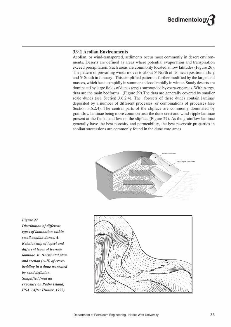
3.9.1 Aeolian EnvironmentsAeolian, or wind-transported, sediments occur most commonly in desert environ-ments. Deserts are defined as areas where potential evaporation and transpirationexceed precipitation. Such areas are commonly located at low latitudes (Figure 26).The pattern of prevailing winds moves to about 5o North of its mean position in Julyand 5o South in January. This simplified pattern is further modified by the large landmasses, which heat up rapidly in summer and cool rapidly in winter. Sandy deserts aredominated by large fields of dunes (ergs) surrounded by extra-erg areas. Within ergs,draa are the main bedforms: (Figure 29).The draa are generally covered by smallerscale dunes (see Section 3.6.2.4). The foresets of these dunes contain laminaedeposited by a number of different processes, or combinations of processes (seeSection 3.6.2.4). The central parts of the slipface are commonly dominated bygrainflow laminae being more common near the dune crest and wind-ripple laminaepresent at the flanks and low on the slipface (Figure 27). As the grainflow laminaegenerally have the best porosity and permeability, the best reservoir properties inaeolian successions are commonly found in the dune core areas.
Grainfall Laminae
Cone-Shaped Grainflows
Figure 27
Distribution of different
types of lamination within
small aeolian dunes. A.
Relationship of topset and
different types of lee-side
laminae. B. Horizontal plan
and section (A-B) of cross-
bedding in a dune truncated
by wind deflation.
Simplified from an
exposure on Padre Island,
USA. (After Hunter, 1977)
34
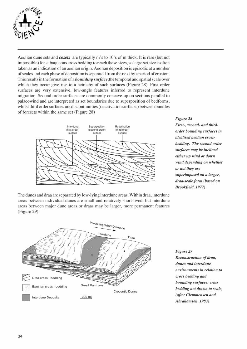
Aeolian dune sets and cosets are typically m’s to 10’s of m thick. It is rare (but notimpossible) for subaqueous cross bedding to reach these sizes, so large set size is oftentaken as an indication of an aeolian origin. Aeolian deposition is episodic at a numberof scales and each phase of deposition is separated from the next by a period of erosion.This results in the formation of a bounding surface;the temporal and spatial scale overwhich they occur give rise to a heirachy of such surfaces (Figure 28). First ordersurfaces are very extensive, low-angle features inferred to represent interdunemigration. Second order surfaces are commonly concave-up on sections parallel topalaeowind and are interpreted as set boundaries due to superposition of bedforms,whilst third order surfaces are discontinuities (reactivation surfaces) between bundlesof foresets within the same set (Figure 28)
Interdune(first order)
surface
Superposition(second order)
surface
Reactivation(third order)
surface
The dunes and draa are separated by low-lying interdune areas. Within draa, interduneareas between individual dunes are small and relatively short-lived, but interduneareas between major dune areas or draas may be larger, more permanent features(Figure 29).
Prevailing Wind Direction
InterduneDraa
Crecentic Dunes
Small Barchans
Draa cross - bedding
Barchan cross - bedding
Interdune Deposits 200 m
Figure 29
Reconstruction of draa,
dunes and interdune
environments in relation to
cross bedding and
bounding surfaces: cross
bedding not drawn to scale,
(after Clemmensen and
Abrahamsen, 1983)
Figure 28
First-, second- and third-
order bounding surfaces in
idealised aeolian cross-
bedding. The second order
surfaces may be inclined
either up wind or down
wind depending on whether
or not they are
superimposed on a larger,
draa-scale form (based on
Brookfield, 1977)

Department of Petroleum Engineering, Heriot-Watt University 35
33Sedimentology
Sedimentary Structures/Features
Depositional Conditions
Modern InterDune Facies Entrada InterDune Facies
*°
Wind ripplesAeolian dune cross strata
Lag grain surfacesDeflation scours
Sand drift behind obstaclesAdhesion laminae
Adhesion ripplesAdhesion warts
Evaporite structures
Contorted structures Rill marks
Algal structures Fenestral porosity
MicrotopographyRain-impact ripples
Brecciated laminae
Wavy laminaeWrinkle marks
ChannelsSmall deltasWater ripples
Subaqueous cross strata
Bioturbation structuresPlant root structures
DRY DAMP WET
The low-lying interdune areas are influenced by different processes than the dunesthemselves and so contain a different suit of sedimentary structures (Figure 30). Dryinterdune areas, where the water table and its associated capilliary fringe lie far belowthe depositioned surface, are dominated by wind ripples and possibly small dunes.Because they are often sediment-starved, winds blowing them will tend to be under-saturated with sediment and may be erosional. If the water table and its capilliaryfringe intersect the interdune surface, the interdune areas may be damp. Wind bornegrains will tend to stick this damp surface, leading to the formation of adhesionstructures. Wetter interdunes may contain moving or standing water, leading to theformation of current ripples, wave ripples and other water-generated structures.Increased organic activity may lead to the preservation of plant rootlets and animalburrows. Deposition of fine material from suspension provides a muddy blanketwhich, on drying, cracks to form typical polygonal desication features. as the waterevaporates, precipitation of evaporite minerals may occur.
Clearly, damp and wet interdune areas will be more extensive during periods of highwater table. These periods may be due to a number of controls, including a rise in seaor lake level or increased rainfall. Whatever the origin, periods of ‘wetting’ and‘drying’ can be identified in many ancient aeolian successions. During wettingperiods, aeolian dunes become less active and may be eroded. Extensive interduneareas may develop and, in more pronounced periods of wetting, fluvial conditions maypredominate. This leads to the development of extensive interdune or fluvial intervals
Figure 30
DIstribution of sedimentary
structures within interune
sediments deposited under
different conditions. Both
modern examples and those
found in the Jurassic
Entrada Formation of the
western USA are indicated
(after Kocurek 1981a)

36
overlying aeolian sediments (Figure 31). As conditions again become drier, rivers willbecome less active, wet interdunes will become drier and large aeolian dunes willagain become more active. Such a drying trend within interdune facies is shown onFigure 31).
Dune Foresets
Wind Ripples and / orSmall Aeolian Cross Strata
Adhesion Laminae
Adhesion RipplePseudo-Cross-Strata
Algal Mat Structures Fenestral Porosity
Water Ripples
Truncated dune Foresets
Both interdune and fluvial sediments have poorer reservoir quality than aeolian dunesands, so that extensive interdune or fluvial intervals may form baffles to vertical flowand therefore tend to compartmentalise aeolian reservoirs (Figure 32).
Figure 32
Distribution of cross-
bedding, bounding surfaces
and interdune deposits in
sections through the
Jurassic Entrada
Formation, Western USA
(after Kocurek, 1981b)
Figure 31
Drying-upwards sequence
of interdune deposits
showing a transition from a
wet to a dry interdune. Dry
interdune conditions are
terminated by the
encroachment of the next
dune. Present-day example.
Padre Island, USA (After
Kocurek, 1981a)

Department of Petroleum Engineering, Heriot-Watt University 37
33Sedimentology
3.9.2 Fluvial EnvironmentsFluvial, or river-deposited, sediments occur in a wide range of climates and tectonicregimes. Rivers flow downhill from the source area towards a lake or the sea and theirform reflects a number of controls including climate (especially rainfall), slope andthe available sediment. The geomorphology and behaviour of rivers form a continuumof types but it is convenient, for discussion of rivers to divide them into somewhatarbitrary classes. The most common classification of river forms identifies four typesof channels (Figure 33).
Low Sinuosity
Sin
gle
Cha
nnel
Straight Meandering
Moderate to High Sinuosity
AnastomosingBraided
Bar surfaces covered during flood stages
Mul
tiple
Cha
nnel
s
The two most common types, which will be discussed here, are meandering andbraided rivers. Meandering rivers have a single channel with a strongly sinuous form(figure 34). Flow in the apical parts of the bends is helical, with surface flow movingfrom the inner to outer bank and flow at the river bed having a component towards theinner bank. The outer bank is eroded and sediment is deposited on the inner bank toform a point bar. Continued erosion of the outer bank and deposition on the point barincreases the amplitude of the meanders and produces relatively narrow necks on thepoint bar. During a severe flood, the point bar neck may be breached, leading to ashortening of the channel course and abandonment of the old meander loop.
Figure 33
Classification of fluvial
channels according to their
shape in plan. (based on
Miall, 1977)

38
Point Bar With Scroll Bars
Crevasse SplayFlood Plain
Fires
Older Crevasse
Splay
Older Charred
Splay
Lateral AccretionSufaces
Meandering channels may transport sandy or muddy sediment but, from a reservoirpoint of view, we are interested mainly in the more sandy rivers. During periods offlooding, the river may flood onto the surrounding low-lying land, the floodplain. Theriver may either break through its banks, to form a temporary crevasse channel, or mayflood over the banks over a longer length. In either case, the flood waters will tend todeposit their coarsest sediment close to the main river, producing thin beds which willtend to become finer and thinner away from the river. Repeated floods over many yearswill produce elevated ridges of sediment, known as levees, close to the channel. Themeandering river will continue to flow along its raised alluvial ridge until, followinga major breach of its banks, it will follow a new path across the lower-relief floodplain.Such avulsion of the channel will abandon the old alluvial ridge downstream of thepoint of avulsion. Thus, meandering river systems will tend to produce complexmeander-belt sandbodies separated by finer-grained floodplain sediments.
Unlike meandering rivers, which have only one active channel at any time, braidedrivers have a number of active channels separated by sandy or gravelly bars (Figure35). Braided rivers tend to form on slightly steeper slopes, and where there is a highproportion of sandy or gravelly sediment.
Figure 34
Block diagram showing the
three-dimensional form of a
meandering river (modified
after Miall, 1985)

Department of Petroleum Engineering, Heriot-Watt University 39
33Sedimentology
Floodplain
Sandbar with superimposed megaripples/dunes
Because of their easily-eroded sandy banks, individual channels in a braided systemwill tend to migrate laterally and to shift their course frequently. The intervening barsmigrate both downstream and across the streams. Braided rivers therefore tend toproduce compound sandbodies consisting of a number of mutually-erosive channelbodies. These multi-storey and multilateral bodies will be both thicker and wider thanthe channel dimensions.
The other two types of channels, straight and anastomosing channels, are rarer and lesswell described than meandering and braided rivers. Straight channels are singlechannels of low sinuosity, and are characterised by side bars which are attached toalternate sides of the channel. Straight channels produce single channel-fill sandbodies.Anastomosing rivers, like braided rivers, consist of a number of active channels whichsplit and rejoin in a down-valley direction. In contrast to braided rivers, with theiractive bars between channels, the individual channels of anastomosing rivers areseparated by larger, finer grained, more stable islands. These islands are commonlylow-lying, boggy and vegetated and the channels do not migrate much laterally. Thisleads to the development of relatively narrow but thick multi-storey sandbodies(Figure 36).
��������yyyyyyyy
����yyyy��yy��yy���������������
yyyyyyyyyyyyyyy����yyyy
Channel Sandstones
Vegetated Island
Figure 36
Block diagram showing the
three-dimensional form of
an anastomosing river
(after Miall, 1985)
Figure 35 Block diagram
showing the three -
dimensional form of a
braided river (after Miall,
1985)

40
The deposits of meandering and braided rivers contain a variety of scales and degreesof heterogeneity. Classically, meandering channels produce erosive-based, upward-fining sandbodies (Figure 37). As well as the vertical variation in grain size andsedimentary structures, the channel sandbodies may also contain inclined lateralaccretion units, which represent deposition on the point bar as it migrated across thechannel (Figure 37). In addition to these within-channel heterogeneities, the meanderbelt sandbody will also consist of a complex of erosive-based channel sandstones andchannel abandonment facies.
Cutbank
SpSt
Sr
Chute
Surface CurrentBottom Current
1.5 M
Lateral accretion units
Lateral accretion is less common in braided rivers, but downstream migration of barsmay lead to the development of downcurrent-dipping or downstream-accretedelements (Figure 38).
In addition to channel forms and laterally-accreted and downstream-accreted units, anumber of other ‘architectural elements’ have been identified in fluvial successions(Figure 39). These have been classified by Miall (1985) and can be used both todifferentiate between deposits of the different channel types and as the basic buildingblocks in reservoir modelling.
Figure 37
Diagrams showing the
development of an upward-
fining trend in meandering
channel sandstones, and
laterally-accreted point bar
deposits. (after Miall, 1985)
Figure 38
Development of
downstream-accreted units.

Department of Petroleum Engineering, Heriot-Watt University 41
33Sedimentology
Ch Channel
FILateral Accretion
SGSediment Gravity Flow
DADownstream Accretion
SBSand Bed Form
LSLaminated Sand
OFOverbank Fines
GBGravel Bar and Bed Form
0.5-5m
As has been shown for both meandering and braided systems, the sandbodiesproduced are generally complex, so that fluvial reservoirs consist of channel beltsandbodies rather than individual channel sandbodies. It should be noted that thegeometry of these sandbodies will be controlled by the stacking pattern and may havelittle relationship to the geometry of the individual channel sandbodies (Figure 40).
Figure 39
The eight basic
architectural elements in
fluvial deposits, (after Miall
1985). No vertical
exaggeration. Note the
variable scale.

42
A
3.5
13
19
17.5
5 2
B
C
D
Latest Channel
Before leaving the fluvial system, it is relevant to consider briefly two other alluvialenvironments. Where rivers leave the confines of a valley, they commonly form conesof sediment known as alluvial fans (Figure 41). In addition to channelised flows,alluvial fans are also influenced by sheet floods, which deposit sheet-like sandstonesand conglomerates. The sediment tends to become finer away from the fan apex andmigration of the fan produces an upward-coarsening trend. Fans commonly form atthe fault-influenced margins of mountain ranges and fault movements may causerejuvenation of the fans and the influx of coarser material. As the newly-upliftedmountains are eroded, the sediment will become progressively finer, leading to thedevelopment of upward-fining ‘megasequences’.
��yy
������������
yyyyyyyyyyyy
������yyyyyy��yy
����yyyy��yy��yy
Siltstones
Cross-bedded Sandstone
Siltstones and Sandstone
Conglomerate and Sandstone
00
2
5 10km
km
Approx. Scale
Figure 40
Diagram to show the lack
of relationship between the
geometry of an individual
active channel and the
geometry of resulting
channel-fill sand bodies
(After Miall, 1985).
Numbers above each
channel are the width/
thickness ratios of the sand
bodies. A,D Simple
Channels; B,E, F, broad
channel-fill complexes
formed by lateral channel
migration or switchng with
little contemporaneous
subsidence; C stacked
channel complex formed by
vertical aggradation.
Figure 41
Alluvial fans

Department of Petroleum Engineering, Heriot-Watt University 43
33Sedimentology
Since the development of sequence stratigraphy, attention has turned to incisedvalleys caused by falls in relative sea level. As the relative sea level falls, the incisedvalleys are largely bypassed by the sediment (Figure 42A) but, as the relative sea levelstabilises and begins to rise, sedimentation will begin in the valley, which willcontinue into the highstand period. The fills of the incised valleys are very complex,and include deltaic sediments as well as fluvial sediments (Figure 42B).
A
B
Incised Valley
Incised Valley SystemShelf / Ramp Non-Incised Fluvial System
MeanderingRiver System
BraidedRiver System
Shoreline / Delta Non-Incised Fluvial System
Hig
hLo
w
Hig
hLo
w
Lowstand (Fan)Systems Tract
Time
Lowstand (Fan)Systems Tract
Time
3.9.3 Coastal and Shallow Marine EnvironmentsThere is a very wide range of clastic coastal environments. In the following sectionwe will describe the beach and shoreface environment, before a discussion of barrierisland and deltaic environments.
Beaches form the boundary between the shallow marine and terrestrial environment.They are dominated by wave processes, but in most cases are also affected by tides.The constituent parts of a beach profile are defined in terms of the tide marks and areshown on Figure 43. The area above the high water mark is the backshore, and the areabetween the high and low water marks is the foreshore. The shoreface extends fromthe low water mark to the fairweather wave base.
Figure 42
Formation and fill of an
incised valley (modified
from Zaitin et al)

44
Spilling Breakers Shoaling Waves
Highwater mark
Lowwater mark
Foreshore BackshoreShoreface
Longshore Bars
Lower Middle Upper
Offshore
Muddy Substrate Sandy Substrate
SkolithosCruzlana
Fairweather Wave Base
Storm Wave Base
5-15
m
ZoophycosIchnofacies
L2
L
Waves begin to build up
Water is driven onto the beach by waves, and then returns to the sea as localisedcurrents. The beach profile is therefore influenced by both waves and currents. As thewaves break on the shore, they produce rapid, shallow currents which flow up thebeach before flowing back into the sea. These swash and backwash currents form theseaward-dipping plane beds which characterise most foreshores. Below the low watermark, the dominant processes on the shoreface depend on a number of factors,including the wave energy. Fairweather waves will tend to produce a mixture of wave-generated bedforms such as wave-ripples and bedforms, including megaripples,produced by wave-driven currents. When a shoreline is dominated by storm waves,the dominant bedform may be hummocks.
As storm-generated currents flow offshore, they transport sediment into deeper water,often as bottom-hugging currents similar to turbidity currents (Figure 44). After thissediment has been deposited, it may be reworked by the storm waves themselves.
Storm-Surge Ebb
Storm Winds
Fairweather Wave Base (FWB)
Turbidity Current
HCS Sands
As storm abates, storm surge ebb currents emerge from washover
channels and flow seawards
Storm surge tide brieflystores sediment-laden
waters in lagoon
Storm Wave Base (SWB)
< 6 m
Geostropic CurrentsStorm Winds
Surface wind-forced current
(FWB)
HCS Sands
Seaward-directed geostropiccurrent, interacting with wave
orbital motions to deposit HCS beds(SWB)
Wind
Surface
Core Flow
Coastal
Downwelling
Bottom
Figure 43
Definition of the beach
profile
Figure 44
Alternative mechanisms of
storm surge ebb currents
and wind-forced or
geostrophic currents for the
generation of storm
deposits. (After Walker
1979, Morton 1981 and
Swift, Figueiredo et al,
1983 Elliott Reading II
Figure 7.6 1985)

Department of Petroleum Engineering, Heriot-Watt University 45
33Sedimentology
In general, the energy is greatest, and the sediment coarsest, on the higher parts of thebeach profile. In deeper water, discrete storm-generated beds may be separated bymudstones whereas, in the more proximal parts of the beach, the sand beds coallesceto form sand-dominated intervals. As a beach progrades offshore, it produces anupward-coarsening facies sequence (Figure 45).
Coastal PlainCoal/BackshoreBeach/Foreshore
Ridge and Runnel/Rip Channels
Middle Shoreface.Swaley Cross - Stratification
Lower Shoreface - Inner Shelf Transition. Hummocky Cross - Stratification
Mid - Shelf.BioturbatedSandy Siltstone
Outer - Shelf.BioturbatedMudstone
Whilst some beaches are joined directly to the main land area, others are separatedfrom it by an area of standing water known as a lagoon (Figure 46). Because of themixing of fresh water and sea water, lagoonal waters are brackish, that is, ofintermediate salinity. The beach ridge on the seaward side of a lagoon is termed abarrier island. At each high tide, water passes through the barrier island into the lagoonvia tidal inlets. In areas with high tidal ranges, these tidal inlets are closely spaced. Ebband flood tidal deltas may form on the seaward and landward side of the inlets, as theconfined flow expands laterally and loses its power.
Figure 45
Typical upward-coarsening
facies sequences produced
by shoreline progradation.
Progradation of the
Shoreline produces a
gradationally-based
succession passing from
outer through inner shelf
deposits into sand-
dominated shoreface and
beach sediments

46
��������yyyyyyyy���
���yyyyyy�����
����������
yyyyyyyyyyyyyyy
������yyyyyy
��yy����yyyy
��yy�y��yy����yyyy
����yyyy
DunesBeach
WashoverTidal Flat
Ebb Tidal Delta
Main Tidal Channel
(Inlet)��yy����yyyy����yyyy
��yy
����yyyy
����yyyy��yy��yy
Flood TidalDelta
Secondary Tidal Channel
Marsh
Tidal inlets migrate rapidly along the barrier island, eroding the upper shoreface andforeshore deposits. The inlet deposits are similar to those of fluvial channels, witherosive bases and upward-fining trends (Figure 47). Migration of the inlets can leadto the upper parts of barrier island successions being dominated by tidal inlet deposits.Barrier islands and beaches will tend to produce linear sandbodies oreiented parallelto the coastline. If the beach or barrier island migrates seaward, it will produce moresheet-like bodies.
���yyy��yy��yy��yy�y0
0
15
301000200030004000
Direction of Channel Migration
Longshore DriftBeach and Dune Ridge
Time Lines
Metres
MetresChannel Deposits
Sea Level
Erosion Surface
Foreshore and Shoreface Deposits
Where a major river reaches a standing body of water, such as a lake or the sea, thebasinal processes will attempt to rework the sediment supplied by the river. If the riversupplies sediment faster than it can be reworked by the basinal processes, the shorelinewill project locally into the basin, forming a delta. On the subaerial part of the deltaplain, the river will split into two or more smaller distributary chanels, which maythemselves split into still smaller channels,causing sediment to be supplied to manypoints along the delta front (Figure 49).
The form of the delta will depend on a wide range of parameters, including climate,tectonic setting, sediment supply and energy of the receiving basin. A commonly-used classification of deltas uses a triangular diagram to compare the relativeimportance of fluvial, tidal and wave processes (Figure 48).
Figure 46
Block diagram illustrating
the various
subenvironments in a
transgressing barrier-island
system
Figure 47
Generalised cross-section
parallel to shoreline
illustrating the development
of a barrier-inlet sand body
by lateral inlet migration.
(Modified from Hoyt and
Henry, 1965).

Department of Petroleum Engineering, Heriot-Watt University 47
33Sedimentology
Elongate
Estuarine
Elo
ngat
e
Loba
te
Cus
pate
6
4
5
Fluvial Dominated
Mahakam
Sao Fransisco
Rhone
NileNiger
Klang-LangatOrd
Wave Energy Flux Tide Energy Flux
WaveDominated
TideDominated
SEDIMENT INPUT
MISSISSIPPI LOBES
6 Modern, 4 St. Bernard, 5 Lafourche
Fluvial-dominated deltas will supply more sediment to the coastline than can bereworked by the basinal processes. The resultant data will therefore form a pro-nounced protuberance of the shoreline. Depending on the depth of water into whichthe delta is prograding, and the degree of reworking, the delta may be either lobate orelongate (Figure 49a and b ). In the case of tidally-influenced deltas, the tidalprocesses will tend to produce a radial pattern of distributary channels which becomebroader towards the basin (Figure 49d). In wave-dominated deltas, a high proportionof the sediment supplied to the river mouth will be reworked into beach ridges oneither side. The resulting delta will, therefore, often cause only a slight deflection ofthe coastline (Figure 49c).
Figure 49
Delta models based on the
relative dominance of
fluvial, wave and tidal
processes (from Fisher et
al, 1969)
Figure 48
Classification of deltas in
terms of river, wave and
tide influence, simplified
from Galloway (1975)

48
It should be noted that the descriptions above are based on deltas dominated by a singleprocess (i.e. plotting near one of the corners of Figure 48). In reality, many deltas, forexample the Nile and Niger, reflect an interaction of two or more processes, and so plotnearer the centre of the triangle (Figure 48).
At the mouths of the distributary channels on fluvial-dominated deltas, the sedimentladen river waters interact with the basinal water. The exact result depends on therelative density of the two waters, the basinal energy and the water depth but, ingeneral, as the fluvial flow expands on leaving the confines of the levees, it loses powerand begins to deposit sediment. This leads to the development of a mouth bar, onwhich the sediment fines away from the apex (Figure 50). Progradation of the deltamouthbar therefore produces an upward-coarsening sequence dominated by current-generated structures (Figure 51).
������������������������
yyyyyyyyyyyyyyyyyyyyyyyy
������������������
yyyyyyyyyyyyyyyyyy
����������������
yyyyyyyyyyyyyyyy��������������������
yyyyyyyyyyyyyyyyyyyy
������������
yyyyyyyyyyyySub Aqueous Leve
e
��yyInterbeddedSands and Silt
Coarsest Sands
FinerSands
Friction-Dominated River Mouth
Channel Middle Ground Bar
Bar Back Bar Front Prodelta
Subaerial
Levee
Subaerial Levee
Subaerial LeveeBar Crest
��������
yyyyyyyyBuoyancy-Dominated River Mouth
�y�y��yy�y�y�y�y�y�y�y�y�y�y�y�y�y�y�y�y�y�y�y�y��yy�y�y�y�y�y�y��yy�y�y�y�y�y�y�y�y�y�y�y�y�y�y�y�y�y�y�y�y�y�y�y�y�y�y�y�y�y�y�y�y�y�y�y�y�y��yy�y�y�y�y�y�y�y�y�y�y�y�y�y�y�y�y�y�y�y�y�y�y�y�y�y�y�y�y�y�y�y�y�y�y�y�y�y�y�y�y�y�y�y�y�y�y�y�y�y�y�y�y�y�y�y�y�y�y�y�y�y�y�y�y�y�y�y�y�y�y�y�y�y�y�y�y�y�y�y�y�y�y�y�y�y�y�y�y�y�y�y�y�y�y�y�y�y�y�y�y�y Distal
Bar
SubaqueousLevee
SubaqueousLevee
��yySilt and
Clay
Channel
Figure 50
Friction-dominated and
buoyancy-dominated river
mouth bars which develop
in shallow-water and deep-
water areas respectively of
fluvial-dominated deltas,
for example in the east and
south of the modern
Mississippi delta (modified
after Wright, 1977)

Department of Petroleum Engineering, Heriot-Watt University 49
33Sedimentology
Progradation of the mouth bar produces elongate sandbodies, known as bar fingersands, which form a radial pattern (Figure 52). It should be noted that the bar fingersands have a considerably greater cross-sectional area than the distributary channelwhich produced them (Figure 52b).
D E E P W A T E R M A R G I N - D E L T A
PL
AT
FO
RM
0
0
0
30
30
30
30
60
60
60
60
BRANCHING PATTERN
Fingers narrow upstream
Interbranch areas widen
seaward
A
������������yyyyyyyyyyyy������yyyyyy
������yyyyyy
��������yyyyyyyyTransitio n Zone
Sands and Silts
������yyyyyyDelta FrontClayey silts
ProdeltaSilty clays, clays
Sparse Fauna
Abundant Fauna
Mud diapir
LENTICULAR CROSS SECTION
Natural LeveeSilty sands, silty clays
MarshOrganic-rich silty clays
Delta PlainSilty sands, silty clays
Sparse toabundant fauna
"Clean"sand zone
B
In contrast, wave-dominated deltas consist of a series of beach ridges associated withthe distributary channels (Figure 53). Their vertical facies sequences will be verysimilar to those produced by prograding beaches (described in the previous section),differing mainly by the presence of associated distributary channels.
Figure 52
Bar finger sands of the
Mississippi delta as
described by Fisk (1961).
Sand contour thickness is
in metres
Figure 51
Typical vertical succession
in a fluvial-dominated delta
front (from Kelling &
George, 1971)
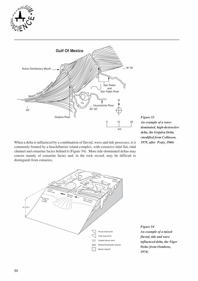
50
Beach Ridge Comple
xes
N
Active Distributary Mouth
93º
18º 30'
92º 30'
Gulf Of Mexico
0 10 20
km
San Pedro and
San Pablo River
Grijalva River
Usumacinta River
When a delta is influenced by a combination of fluvial, wave and tide processes, it iscommonly fronted by a beach/barrier island complex, with extensive tidal flat, tidalchannel and estuarine facies behind it (Figure 54). More tide-dominated deltas mayconsist mainly of estuarine facies and, in the rock record, may be difficult todistinguish from estuaries.
Figure 53
An example of a wave-
dominated, high-destructive
delta, the Grijalva Delta.
(modified from Collinson,
1978, after Psuty, 1966)
Figure 54
An example of a mixed
fluvial, tide and wave
influenced delta, the Niger
Delta (from Oomkens,
1974)

Department of Petroleum Engineering, Heriot-Watt University 51
33Sedimentology
From a detailed study of the vertical succession of facies in preserved deltaicsuccessions, it is often possible to differentiate between the deposits of the differentdelta types. This can be done either by the study of cores or simply by wireline loginterpretation (Figure 55). From this interpretation, it is possible to map the sandbodydistribution in the subsurface using a model derived from the interpretation (Figure 56).
Figure 56
Sandbody geometries of the
six delta types of Coleman
and Wright (1975) plotted
on the river-, wave- and
tide-dominated tripartite
classification of Galloway
(1975).
Figure 55
Subsurface interpretation
of fluvial-dominated deltaic
reservoirs

52
Another important phenomenon frequently associated with deltaic deposits is theformation of growth faults. Deltas commonly lead to the rapid deposition of sediment,which thins, and therefore slopes, towards the basin. This may encourage thedevelopment of early syn-sedimentary normal faults, which generally dip towards thebasin and are often curved, or listric, in form. These ‘growth faults’ producedlocalised topographic lows in their downthrown side, which may act as depocentresfor coarse grained sediment. Rollover of the beds on the downthrown side may alsolead to the development of anticlinal traps. Thus, the occurrence of growth faults cancontrol the distribution of both reservoir sandbodies and traps in deltaic environments.In some deltas, such as the Niger, growth faults are one of the major controls onhydrocarbon distribution (Figure 58).
Figure 57
Inter-relationships between
flow initiation, transport
and deposition of and by
sediment gravity flows.
Figure 58
Niger Delta growth fault
traps (from Elliot,1978,
after Weber and Daukoru,
1975)

Department of Petroleum Engineering, Heriot-Watt University 53
33Sedimentology
3.9.4 Deep Marine Clastic EnvironmentsThe physical processes, such as tides and waves, which dominate coastal and shallowmarine environments are generally absent or ineffective in the deep marine environ-ment. For the majority of time, the deep oceans are low-energy environments in whichfine grained carbonate or clastic muds are able to accumulate. Coarse-grainedsediment is transported into these environments by a number of infrequent and short-lived processes, of which the sediment gravity flow processes (slumps, debris flows,turbidity currents etc.) are dominant. Our discussion of the deep water environmentwill, therefore, concentrate on the deposits of these processes.
Sediment gravity flows were discussed in Section 3.6.2.5. It should be noted that thedominant process in a gravity flow may change with time and space as the flowdevelops (Figure 60). In recent years, there has been much discussion in the literatureconcerning the differentiation of the deposits of high-density turbidity currents andsandy debris flows. It is likely that many of the deposits in question may have beentransported over long distances by turbidity currents but, immediately prior todeposition, the lower parts of the currents took on the characteristics of a debris flow.The deposits, which record only their mode of deposition, rather than their long-distance transport, therefore resemble debris flow deposits.
The earliest deep marine sandstones to be studied in detail were turbidites. The faciespresent in an idealised ‘classical’ turbidite are summarised by the Bouma sequence(Figure 60). For many years, this was thought to be the paradigm for all turbiditesandstones. However, later work showed that many deep-water sandstones did not fitthis idealised model, so a number of new models for the deposits of single sedimentgravity flow were proposed (Figure 61).
Figure 59
Inter-relationships between
flow initiation, transport
and deposition of and by
sediment gravity flows

54
A
E (h)
E (t)
(D)
C
B
A
Sole Marks
Turbidity Current
Fluidized / Liquified Flow
Rippled or flat topCross lamination, Climbing ripples
Laminated
Good grading("Distribution grading)
Flutes, tool marks on base
Sand volcanoes or flat topconvulate laminationfluid escape "Pipes"
Dish structure?
Poor grading("Coarse tail grading")
? Grooves, flame and loadstriations structures on base
Grain Flow
Debris Flow
Flat top
Irregular top(Large grains projecting)
No grading ?
Massive,grain orientation parallelto flow
Massive,poor sorting random fabric
Poor grading, if any ("Coarse tail")
Basal zone of "Shearing" broad "Scours"? Striations at base
Reverse grading near base?Scours, injection structures
In many of the early outcrop studies, relatively little attention was paid to the verticaltrends within turbidite successions. However, careful examination of some turbiditesuccessions demonstrates the occurrence of facies sequences in which the thicknessand/or mean grain size of the sandstone beds increases or decreases upwards. Thesetrends were attributed to deposition on different parts of a submarine fan (Figure 62).Submarine fans occur offshore from major river systems or off the continental shelfin many parts of the world. Like deltas, they are sourced from a single point and contain
Figure 61
Facies models for
turbidites, debris flow
deposits (debrites) and
slump deposits.
Figure 60
The Bouma sequence for a
classical turbidite (Bouma,
1962). Division A is
structureless; B is parallel-
laminated sand; C is
rippled and/or convoluted;
D consists of parallel-
laminated silt and mud.
The pelitic interval E is
partly of turbidite origin (t)
and partly hemipelagic (h).

Department of Petroleum Engineering, Heriot-Watt University 55
33Sedimentology
a system of distributary channels supplying lobes. The upward-thickening trends inturbidite sequences are attributed to the progradation of fan lobes and the upward-thinning trends to deposition within a channel. It should be noted, however, that thismodel is somewhat simplistic, and that the thickening or thinning trends may be verysubtle.
In addition to point-sourced fan systems, multiple-sourced systems also occur. Thismay cause the separate fan systems to overlap and coalesce, forming a more ramp-likesystem (Figure 63). Away from the submarine fans or ramp systems, turbidites maynot be organised into upward-thickening or upward-thinning trends. Such successionsare commonly attributed to deposition on the basin plain.
Within deep marine clastic systems, a number of architectural elements can beidentified. These include channels, lobes and sheets, as well as slumps and slides. Themain reservoir targets are sand-rich channels and lobes, although the other architecturalelements may also form good reservoirs under certain conditions.
Figure 63
Multiple-source submarine
ramp in a sand-rich system
Figure 62
Single point-source
submarine fan in a sand-
rich system

56
As in the case of the other depositional systems described above, a detailed examinationof 1D well data (either wireline logs or core) from deep water clastic successions mayenable sedimentary trends to be identified and a three-dimensional model of thesystem to be built (Figure 64).
3.10 CARBONATE SEDIMENTS
3.10.1 IntroductionIn many parts of the world, beaches are dominated by quartz sand and, for those of usbrought up in these areas, it is tempting to believe that this must be the caseeverywhere. However, in other parts of the globe, carbonate sands are the norm. Itshould be remembered that the ‘natural’ sediments in marine environments arecarbonates; it is only when clastic material is brought into the area in sufficientquantities to subdue carbonate-secreting organisms, and to dilute what carbonatematerial is being formed, that clastic sediments result.
Carbonate sediments have many things in common with clastic sediments, but also anumber of important differences.
Figure 64
Log signatures of a single
point-source mixed sand-
mud fan system

Department of Petroleum Engineering, Heriot-Watt University 57
33Sedimentology
Whereas the majority of clastic grains have their origin some distance from the siteof their deposition, many carbonate grains are formed at or very close to their eventualsite of deposition. A small proportion of these carbonate grains are precipitateddirectly from marine or lacustrine water, but the majority are precipitated by, or withthe assistance of, plants or animals. Many carbonate rocks are composed almostentirely of the broken shells of marine animals, which may have been transported onlya short distance.
Because the majority of clasts, and matrix, in carbonate sediments are composedinitially of various forms of calcium carbonate, they are more soluble than most clasticrocks. The ions liberated by dissolution will then be available for precipitation ascarbonate cements. Carbonate sediments are therefore likely to undergo earlierdissolution and/or cementation than clastic sediments.
Because of these differences, it is often forgotten that, under certain circumstances,carbonate sediments behave in essentially the same way as clastic sediments. In thoseareas where carbonates predominate, the carbonate grains respond to the physicalprocesses of the environment in the same way as any other type of sand. In current-dominated environments, carbonate grains may be transported in megaripples, and soform cross bedding, whilst wave-ripples may form in wave-influenced carbonateenvironments. Well-bedded deep marine carbonates commonly have all the charac-teristics of clastic turbidites.
3.10.2 Carbonate GrainsBioclastsAs mentioned above, the majority of carbonate grains are precipitated by organisms,as internal or external skeletons, or by biochemical processes mediated by organisms.Clasts derived from skeletal material are known as bioclasts. These may consist ofwhole skeletons, but are much more commonly broken fragments of skeletons. In themarine environment, a wide range of organisms, including bivalves, brachiopods andgastropods, produce external shells, whilst others, such as echinoids and crinoidshave internal calcite skeletons and some, like corals, produce frameworks in whichsmall colonial organisms can live. Some algae (e.g. Halimeda) also produce calcar-eous hard parts and these may be the dominant bioclasts in some environments.
On the death of these organisms, their hard parts become available as potential clasts.In some cases, the shells remain in situ and unbroken , but they are more commonlytransported by waves or currents and become broken and/or rounded during transport.The mineralogy and crystalline structure of skeletal material varies from organism toorganism, so that organic debris generally has a greater range of shapes and densitiesthan terrigenous clastic sands. This obviously has an influence on their hydrodynamicbehaviour and can lead to efficient sorting of the different grain types.
OoidsOoids are small (less than 2mm) near-spherical carbonate grains with a pronouncedconcentric structure. They generally form in moderate to high energy shallow marineenvironments. In the past, there has been much debate over their origin, but theirgrowth is generally accepted to be associated with algae, which bind the fine-gainedsediment of which they are composed, and may also have a role in the precipitation

58
of the carbonate material. Larger, concentrically-structured algal nodules, known asoncoids, also occur in some marine and lacustrine environments.
IntraclastsBecause carbonate sediments may be subject to earlier cementation than terrigenousclastic sediments, it is common for carbonates to be lithified at, or close to, thesediment surface. If erosion then occurs, instead of breaking up into individual grains,the sediment may break into groups of grains lightly cemented together. Thesecompound clasts are known as intraclasts.
3.10.3 Minerals PresentAs mentioned above, different organisms precipitate hard parts composed of differentminerals. The majority of shelly material is composed of calcium carbonate, but thismay occur in several forms. The most stable mineral, and that which occurs in mostold carbonate rocks, is calcite. However, many organisms, including bivalves,gastropods and many corals, precipitate skeletons of a different form of calciumcarbonate, known as aragonite. Aragonite is less stable than calcite and is thereforeeasily dissolved (see Section 3.11). Calcite may also occur as 2 different forms, highMg calcite and low Mg calcite. Of these two, High Mg calcite is less stable. Otherorganisms may produce hard parts composed of phosphate minerals.
The other minerals common in carbonate rocks form by diagenesis (see Section 3.11)and include iron-rich ferroan calcite, dolomite (calcium magnesium carbonate) andsiderite (iron carbonate).
3.10.3 Classification of Carbonate RocksIn addition to the grain types, carbonate sediments may also contain carbonate mud,or micrite. Micrite may form by the physical abrasion of clasts during transport, butis also produced by the organic breakdown of clasts. Dead shelly material iscommonly colonised by organisms such as algae, which bore into the surface of theshells and, in doing so, produce fine-grained micrite. This algal boring is often seenin the form of dark ‘algal rims’ on bioclasts.
The main components of carbonate sediments are therefore a range of grain typesincluding bioclasts, ooids and intraclasts, and micrite mud. An early classificationscheme for carbonates, proposed by Folk in 1973, divides carbonate rocks on the basisof the clast types and the presence of matrix or cement. Carbonate rocks with micritematrix are given the suffix -micrite, whereas those with crystalline ("Spary") cementare given the suffix -sparite. Thus a rock composed of bioclasts in a micrite matrix isa bio-micrite. If it contains little or no matrix, but has a sparry cement, it is a bio-sparite.If more than one clast type is present, the different clasts are listed in decreasing orderof abundance, for example oo- bio-sparite, bio- intra-micrite.
A later classification concentrates on the primary grain and matrix texture and ignorescement (Dunham, 1962;). Carbonates consisting only of grains and cement, with nomatrix, are known as grainstones. Those with some matrix, but with a clast-supportedfabric, are packstones, whilst those with a matrix-supported fabric are wackestones.Carbonate rocks consisting mainly of micrite, with less than 15% grains, are knownas mudstones. It should be noted that the mud in this case is carbonate material, in

Department of Petroleum Engineering, Heriot-Watt University 59
33Sedimentology
contrast with terrigenous mudstones, which are composed mainly of clay minerals. Toavoid confusion, it is sometimes better to refer to these sediments are carbonatemudstones. In addition to these textural terms, further terms are needed to describesediments strongly influenced by growing organisms. Where a rigid framework isbuilt, for example on coral reefs, the resulting rock is a framestone. Where growinganimals or plants reduce the power of currents or waves, leading to the deposition ofsediment, the sediment is a bafflestone.
3.10.4 Carbonate Depositional EnvironmentsAs described above, carbonate depositional environments will not be discussed in asmuch detail as the clastic environments and the discussion in the following sectionswill concentrate on those features of relevance to the reservoir performance of therocks. The majority of carbonates are deposited in marine or lacustrine environments;we will concentrate here on marine environments.
Shallow marine environments are sites of high biological diversity and productivity.Particularly in areas of low clastic input, carbonate clasts, such as bioclasts and ooids,and carbonate mud will form the dominant sediment. Carbonate sands will be washedonto the beach, so that the coastal and shallow marine environments are dominated bycarbonate deposition. This is the case in many modern dry, low-latitude areas, suchas the Gulf coasts.
In the shallow marine waters, waves and tides rework the sandy sediment into shallowbars or shoals. In general, the energy will be highest on the topographically higher,shallower water parts of the shoals. The sediments are therefore coarser grained andbetter sorted at the top of shoals and lateral migration of a shoal will produce anupward-coarsening sequence, with mudstones and wackestones being replacedupwards by coarser grained packstones and grainstones. Between the shoals, thesediment is likely to be finer grained and dominated by mudstones and packstones.
The organisms living in this environment commonly occur in great abundance incertain areas. A combination of the accumulation of skeletal debris and the bafflingeffect of the living organisms can lead to the development of a mound of sedimentknown as an organic buildup. These buildups commonly contain high concentrationsof coarse skeletal material, such as crinoids and rudist bivalves. If a framework oforganic material is built, for example by colonial corals, a reef results. Reefs are verycomplex environments, which include both living and dead corals, as well as a largenumber of other organisms which live on or near the reef. The reef may contain holesand caves, and a talus slope of broken coral debris may form on the seaward side.
Shoals, buildups and reefs may all protect the area on their landward side from thehighest wave energy, allowing a low-energy lagoonal environment to develop. Theselagoons are generally dominated by fine-grained carbonates, but may contain localshoals and buildups.
In tidal environments, extensive areas of carbonate tidal flats may develop. Theseconsist of horizontally bedded fine grained carbonates cut by tidal channels of varioussizes. The fills of the channels are generally coarser grained and cleaner than the tidal

60
flat sediments. The topographically higher parts of the flats may be exposed at lowtide, and so be subjected to repeated wetting and drying. This can lead to thedevelopment of a number of distinctive features such as mud cracks, tepee structuresand fenestrate fabrics.
Progradation of carbonate tidal flats or beaches leads to the development of extensiveareas of low-lying coastal plain or sabkha. Marine waters may soak into the sabkhasediments and evaporate from surface of the sabkha, precipitating a range of evaporiteminerals and causing complex early diagenesis (see Section 3.11).
3.10.5 Porosity in Carbonate RocksIn addition to the porosity types present in clastic sediments, carbonates also containa number of types of pores which occur exclusively in carbonates or are moreimportant in carbonates than in clastic sediments.
Vuggy poresBecause of the variable chemistry of many carbonate clasts, there is a likelihood ofpartial or total dissolution of the less stable clasts. Dissolution of, for example, largearagonite bioclasts can lead to the development of large secondary pores. These vuggypores are commonly isolated from each other within a lower-porosity matrix.
Intragranular poresMany bioclasts, such as bivalves, are hollow or, in the case of corals or crinoids, havea microporous texture. There is therefore a possibility of high proportions ofintragranular porosity in bioclast-rich carbonates.
Shelter porosityPlaty clasts, such as broken shells, may protect the area underneath them fromsediment falling from above. This area may therefore remain empty, as shelterporosity, or be more loosely packed than the surrounding sediment.
FenestraeShrinking associated with repeated wetting and drying can cause sedimentary laminaeto pull apart, producing irregular pores or fenestrae (from the Latin for window).
Intercrystalline porosityRecrystallisation of carbonate rocks may cause changes in volume. For example,dolomitisation of calcitic or aragonitic sediment involves a slight decrease in volume.Thus the dolomite crystals may not fill the entire volume, allowing intercrystallineporosity to exist between the dolomite crystals.
Fracture porosityFractures may occur in all lithologies, but they are particularly common in carbonaterocks because the early cementation of many carbonates causes them to behave in abrittle manner for most of their history. Fractures are also very important because thepermeability of many carbonates is low, even for relatively high porosities, so fluidflow may depend on the presence of fractures. Also, many of the porosity typesdescribed above (e.g. vuggy, fenestrate and intragranular porosity) commonly consistof large but unconnected pores, which will only form an effective flow network iffractures are present.

Department of Petroleum Engineering, Heriot-Watt University 61
33Sedimentology
3.11 DIAGENESIS
3.11.1 DefinitionDiagenesis consists of the range of physical and chemical processes and changeswhich turn a sediment into a rock. It may begin immediately after deposition andcontinues during burial. The majority of diagenetic changes will tend to reduce theporosity and permeability of a sediment, but some, such as dissolution, may increasethe porosity and/or permeability.
In the following section, we will be concerned only with those aspects of diagenesiswhich impact on porosity and permeability and therefore on reservoir performance.
3.11.2 Clastic DiagenesisAs sediments are buried, they undergo compaction due to the weight of the overlyingsediment. Initial compaction may occur by a change in packing of the grains, but oncean efficient packing pattern has been established, further compaction can occur onlyby grain deformation. The high pressure at grain contacts may cause local dissolution,leading progressively to straight, concavo-convex and sutured grain contacts (Figure3.4). Grains may also deform brittly, by breaking, or may deform ductily. Certain clasttypes, such as mudstone intraclasts and lithic clasts, are more liable to deform ductily,so sediments containing high proportions of these clasts are likely to lose a higherproportion of their porosity by ductile deformation than, for example quartz-richsands.
Clastic sediments may be cemented by a wide range of mineral cements and clays. Thetype and distribution of the cements will depend partly on the burial history of thesediment. The majority of cements are precipitated from pore waters, so the type ofminerals precipitated, and their order, will reflect the changes in water chemistry withtime. At shallow burial depths, the pore waters will contain micro-organisms such asaerobic and anaerobic bacteria which will influence the water chemistry. Duringburial, the sediment may be surrounded by the same water for a long period of time,in an essentially closed system, or circulation of water may constantly replenish thewater or replace the pore water with water of a different chemistry. A full study of thegeochemistry of diagenesis is beyond the scope of this chapter, but the followingparagraphs are a brief introduction to some of the more important points.
Immediately after deposition, the pore spaces in most sediments will be occupied byeither fresh or marine waters, depending on the environment of deposition. Fluvial oraeolian sediments may be deposited above the water table, so will have little or nowater round the grains. However, sediment in this vadose zone may become wetfollowing periods of rainfall or may be affected by water rising from the water tabledue to capillary action. Water may occur as thin rims round the grains, as meniscibetween grains or as pendulous drops hanging from grains. As cements are onlyprecipitated were water is present, vadose zone cements may have a distinctive form,either rimming grains, bridging the gap between grains at pore throats, or being thickeron the lower side of grains. Continued burial of sediments in the vadose zone willeventually move them below the water table.

62
Cements precipitated below the water table can grow anywhere in the pore spaces, butit is still common for cement crystals to be nucleated on sediment grains. Silica cementmay nucleate on quartz grains, where it grows with the same crystal orientation as thehost grain and is said to be in 'optical continuity'. These quartz overgrowths can oftenbe differentiated from the host grain by a thin dusty rim marking the original marginof the grain. Feldspar overgrowths may also occur, though they are rarer than quartzovergrowths.
Many sandstones are cemented by carbonate minerals, including calcite, dolomite andsiderite. The cements may rim the grains or may occur as small crystals in theintergranular pores. Calcite and dolomite often form cements with crystals which aresignificantly larger than the grains and so enclose a number of grains. Thesepoikilotopic cements are sometimes visible even in hand specimen, as the largecrystals sparkle with reflected light.
In addition to mineral cements, clays minerals may also be precipitated in the porespaces. These authigenic clays may have a variety shapes and relationships to the hostsediment. Most clay minerals form plate-like crystals, and several minerals, includingchlorite and illite may grow on grains as concentric or radial arrangements of plates.The radial arrangement is more common. In addition to its platy fabric, illite also formsmore elongate crystals, and this fibrous or ‘hairy’ illite commonly grows at themargins of more platy illites. Other clays, such as kaolinite, tend to form denserclusters of crystals, arranged like the pages of a book, in intergranular pores.
In the case of sands with high proportions of clay, detrital clays may increase in sizeduring burial by the addition of authigenic overgrowths or may be replaced by otherclay minerals. In general, the clay-rich matrix tends to become better crystallised withincreasing depth of burial. As the pressure and temperature increase during burial thesediment may pass from the stability field for one clay mineral into that for another.For example, smectite is generally replaced by illite with increasing depth, with themost pronounced change occurring at depths of between 2.5k m and 3.5km. The illitecrystallinity increases with burial and can be used to give an estimate of the maximumburial depth of a rock.
Thin section petrography and scanning electron microscopy are used to examine theauthigenic mineral fabrics and the relationship between different cements and clays.For example, it maybe possible identify cements growing over other cement mineralsor clays. By a detailed study of the relationship of the different cements and authigenicclays, it is possible to establish the order of diagenetic events. This diagenetic historyenables important information to be gained about both the burial history and theevolution of the pore waters.
3.11.3 Carbonate DiagenesisAs mentioned above, carbonate sediments are prone to early diagenesis and mayundergo many phases of cementation during burial. Early cements, particularly thoseprecipitated in the vadose zone, may form rims round the grains. Both calcite andaragonite may grow in this way and may show many of the characteristic features ofvadose cements described in Section 3.11.2.

Department of Petroleum Engineering, Heriot-Watt University 63
33Sedimentology
Many bioclasts and the majority of micrite are initially composed of aragonite, whichis an unstable mineral under normal burial conditions. If a clast is totally dissolved,its original form may be preserved as a mould, either by the surrounding matrix or byan early rim cement. The clast-shaped pore then behaves like any other pore and maybe later filled by cement. Alternatively, unstable grains may be gradually replaced byanother mineral, a process known as neomorphism. In this case, a ghost of the originaltexture may be preserved.
Pore-filling calcite cement commonly develops a distinctive fabric. The initial porelining consists of a large number of small, blade-like crystals. As they continue togrow into the pores, some crystals grow over their neighbours, reducing the numberof active crystals. The cement crystals therefore tend to increase in size towards thecentre of the pore.
Diagenetic dolomite may occur either as rhombic crystals in the pore spaces or as moreextensive pore-filling or poikilotopic cement. It may also replace the existing clastsand matrix, producing a sedimentary rock composed entirely of dolomite. In somedolomites, the original fabric of the sediment is entirely lost, but in others the faintrelict structure is visible.
In any dissolution or recrystallisation, the least stable minerals or grain types tend tobe dissolved or replaced first. It is fairly common for bioclasts of a certain type to beentirely replaced by a diagenetic mineral, whilst others are either unaltered or arereplaced by a different mineral.
Although diagenesis of carbonates generally involves a smaller number of mineralsthan clastic diagenesis, it often involves many phases of dissolution, replacement andcementation. Many carbonate minerals can contain variable proportions of certainions. For example, the proportion of iron in ferroan calcite or ferroan dolomite mayvary, and it is often possible to identify distinctive growth zones of subtly differentchemistry within a single crystal. Other ions present only in trace amounts may alsovary in their proportions, and special techniques may be used to identify more subtlezonation.
As in the case of clastic diagenesis, it is possible, by using a variety of techniques, toidentify diagenetic sequences in carbonates and to postulate a burial history and porewater evolution. For example extensive dissolution may indicate the presence ofmeteoric water, and so may suggest a period of uplift.
3.11.4 Impact of Diagenesis on Porosity and PermeabilityThe majority of diagenetic processes lead to a reduction of porosity and permeability,as the sediment is compacted and authigenic minerals fill the pore spaces. It shouldbe noted, however, that the timing, mineralogy and fabric of cements and authigenicclays can produce very different results.
Even quite low volumes of early cement may reduce the degree of compaction of asediment during later burial and may therefore increase its porosity at a given depth.
The shape and position of mineral cements may also have a significant impact onpermeability. For example, a certain volume of meniscus cements occurring near pore

64
throats will have a greater impact on permeability than the same volume of cementspread more evenly throughout the rock. In the same way, clay minerals have asignificantly greater impact on permeability than mineral cements, but the degree oftheir influence will also depend on their fabric and location. Radial platy clays willrestrict flow more than tangential clays, as they extend further into the pore spaces. Fora given volume of clay, fibrous illite will have the greatest effect, particularly if itoccurs in pore throats. In contrast, kaolinite is often more patchilly developed, andmay have little or no effect on the majority of pores.
Dissolution of grains (for example feldspars in clastic rocks and aragonitic bioclastsin carbonates) will produce secondary porosity. However, this increase in porositymay have little impact on permeability if the dissolution pores are not well connectedto the existing pore system. Dolomitisation may also lead to an increase in porosityand permeability, due to the reduction in volume it involves.
Before leaving the subject of diagenesis, it is relevant to look briefly at the impact ofman on the rock. Poor drilling or production methods may cause physical or chemicalchanges in a rock which may be deleterious to its reservoir performance. For example,production at too high a rate, particularly near the well bore, may cause clay mineralsto move, leading to the clogging of pore throats. Also, chemical techniques such asacidisation, used to improve the permeability, may have the reverse effect if the acidsalter the clay minerals or cause them to move. It is vitally important, therefore, beforeundertaking any programme of acidisation, to understand fully the diagenetic natureof the rock, so that the reaction of the fluids introduced into the reservoir can beestimated.