geology i - fitstaff.fit.ac.cy/eng.gm/geology i (aceg209)/geology i notes by... · geology i notes...
TRANSCRIPT
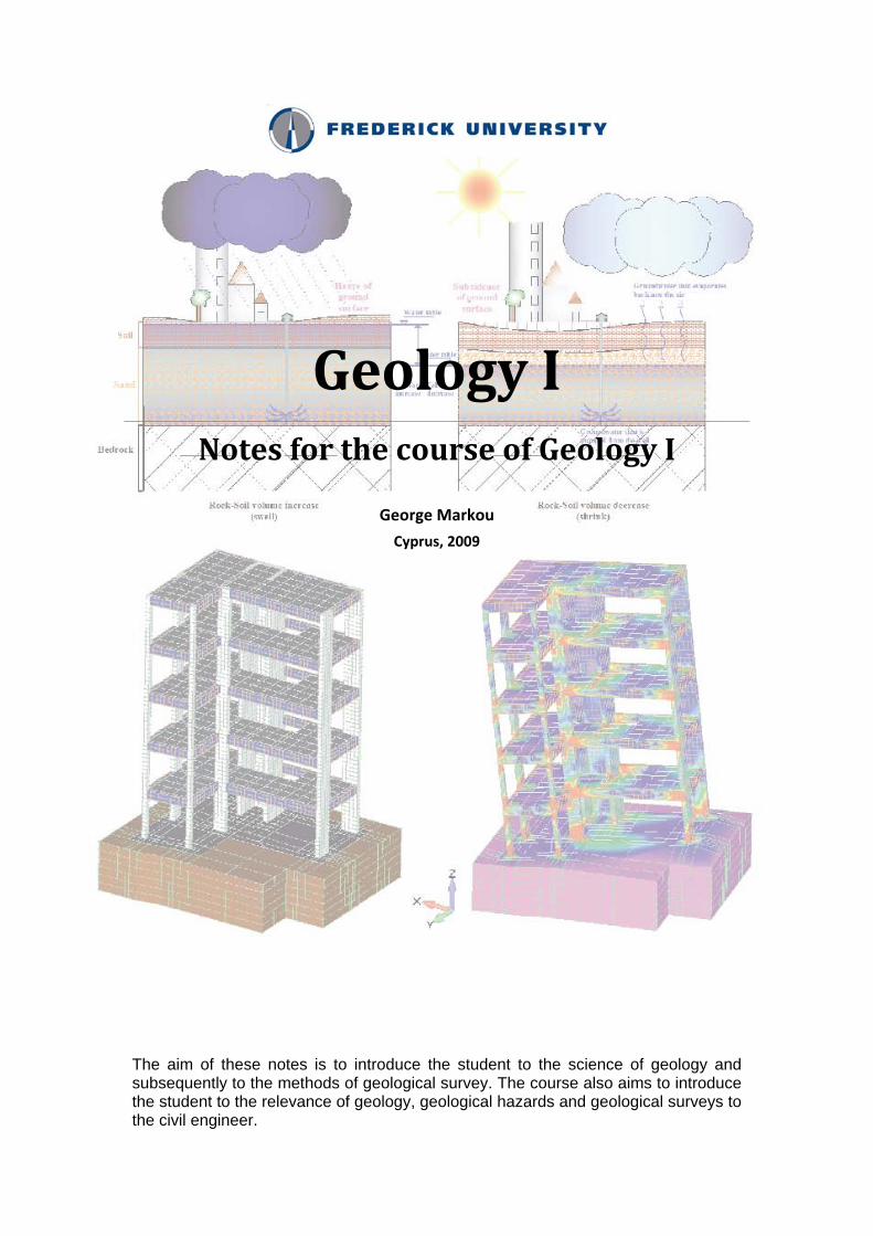
Geology I Notes for the course of Geology I
George Markou
Cyprus, 2009
The aim of these notes is to introduce the student to the science of geology and subsequently to the methods of geological survey. The course also aims to introduce the student to the relevance of geology, geological hazards and geological surveys to the civil engineer.


[email protected] George Markou Cyprus, 2009
i | P a g e i
ACEG209, Geology I
Contents 1. Introduction ....................................................................................................................................................... 1
2. General information about Earth’s Geology ....................................................................................................... 3
3. Geology of Cyprus ............................................................................................................................................... 6
4. Minerals and Rocks ............................................................................................................................................. 7
4.1 Minerals ........................................................................................................................................................ 7
4.2 Rocks ............................................................................................................................................................. 7
4.2.1 Igneous rocks ......................................................................................................................................... 8
4.2.2 Metamorphic rocks ................................................................................................................................ 9
4.2.3 Sedimentary rocks ................................................................................................................................ 10
5. Earth Surface Processes .................................................................................................................................... 13
Erosion, transport and deposition ................................................................................................................ 14
6. Geological Hazards ............................................................................................................................................ 15
6.1 Slope failure ................................................................................................................................................ 15
6.2 Earhquakes .................................................................................................................................................. 16
6.3 Volcanic eruptions ....................................................................................................................................... 16
6.4 Geological disaster of the Malpasset dam .................................................................................................. 17
6.5 Geological disaster of the Vajont dam ........................................................................................................ 18
7. Structural geology ............................................................................................................................................. 21
7.1 Faults ........................................................................................................................................................... 21
7.2 Folds ............................................................................................................................................................ 22
7.3 Strain (Distortion) ........................................................................................................................................ 23
8. Ground water .................................................................................................................................................... 24
9. Site Investigations ............................................................................................................................................. 29
10. Plate tectonics ................................................................................................................................................. 33
11. Geologic Maps and Geologic Sections ............................................................................................................ 37

[email protected] George Markou Cyprus, 2009
1 | P a g e 1
1. Introduction
Geology is the science which studies the Earth and helps Engineers design accordingly their structures (underground or surface structures). The objective of a Geotechnical study is to:
1. Check if the surface and the inside of the Earth are capable of bearing our structures and conclude to the foundation type that is going to be implemented. The study will find potential problems and will recommend their solutions.
2. Check the Earth’s and subsoil’s mechanical properties if they are going to be used as materials in our structures.
3. Check the subsoil’s characteristics that may be affected by potential structures in order to prevent environmental problems (i.e. pollute underground water, build a dam that will stop the course of anadromous fish like salmon).
All Civil Engineers’ structures are founded on the Earth’s surface or its subsoil and therefore a geotechnical study is always required in order to design the proper foundation for each structure case. Therefore, according to the structure type at hand, Civil Engineers must collect all necessary site data and any other kind of information that will help them derive important conclusions about the geological history and mechanical properties of the soil, subsoil or rock that their structures are going to be built on. In order to achieve this, one must know:
The Earth material substance and corrosion that may affect the surface of the Earth. The geometry in space of the subsoil. The existence of faults and groundwater table. The mechanical features of the earth material (soil – rock – bedrock).
The type of foundation that each structure is going to use in order to transfer its forces to the ground is analogous to the structure and soil type. If the goal is the structures optimum design with minimum cost then economical criteria must be taken into consideration.
It is obvious that for the achievement of the above task, a good knowledge in geology, mineralogy-
petrology, material and structural mechanics is required. An additional tool that civil engineers have in order to interpret geological phenomenon is the geological map. The ability to read, comprehend and therefore extrapolate significant geological information from geological maps is important.
Before continuing with the rest of the chapters, a very important modus operandi has to be mentioned here for future consideration:
“No one can antagonize nature; that’s why Engineers must always collaborate with nature.”
Therefore, technical geology is the tool that helps us to understand better the Earth’s geological

[email protected] George Markou Cyprus, 2009
2 | P a g e 2
phenomenon, in order to have the ability of designing structures that will last through time without harming their surrounding environment.
(a) (b)
Figure 1. a) Foundation wall with footer and b) General foundation with piles.
Figure 2. Finite Element Method (FEM) model of a 5str reinforced concrete building with general foundation. (left) FEM model and (right) Deformed FEM model with stress contour.

[email protected] George Markou Cyprus, 2009
3 | P a g e 3
2. General information about Earth’s Geology
The geological history of the Earth began 4.6 billion years ago and will change throughout the years through volcano eruptions and tectonic movements. Man has been on Earth for the past 2 million years which is equal to 0.04% of its geological history. In order to make the study of Earth’s history easier and to group its evolution through time, certain periods were created which are depicted in Table 1.
Table 1. Main Geological Ages
Age Period Description
250 million years from now
Pangea
Ultima
(FUTURE)
Collision of continents
Present to 1.8 million years BP
Quaternary
Period Humans appeared on Earth. Modern world.
65 to 1.8 million years BP
Tertiary Period
Extinction of dinosaurs. The oceans had widened, and India approached the southern margin of Asia
146 to 65 million years BP
Cretaceous
Period
Dinosaurs dominated until mass extension at end of this period. South Atlantic Ocean opened. India separated from Madagascar. North America was connected to Europe.

[email protected] George Markou Cyprus, 2009
4 | P a g e 4
208 to 146 million years BP
Jurassic
Period
Large Dinosaurs, first birds and flowers. South-central Asia had assembled.
248 to 208 million years BP
Triassic
Period
The first dinosaurs and mammals appeared. The supercontinent of Pangea, mostly assembled by the Triassic.
540 to 248 million years BP
Paleozoic
Era
Complex marine life. First plant, insect and reptile life on land.
2.5 billion to 540 million years BP
Proterozoic
Eon
Primitive marine life. This map illustrates the break-up of the supercontinent, Rodinia, which formed 1100 million years ago. The Late Precambrian was an "Ice House" World, much like the present-day.
4.6 billion to 2.5 billion years BP
Archeozoic
and Hadean
Eons
One-celled organisms evolve releasing oxygen into atmosphere.
BP: Before Present
[email protected] George Markou Cyprus, 2009
5 | P a g e 5
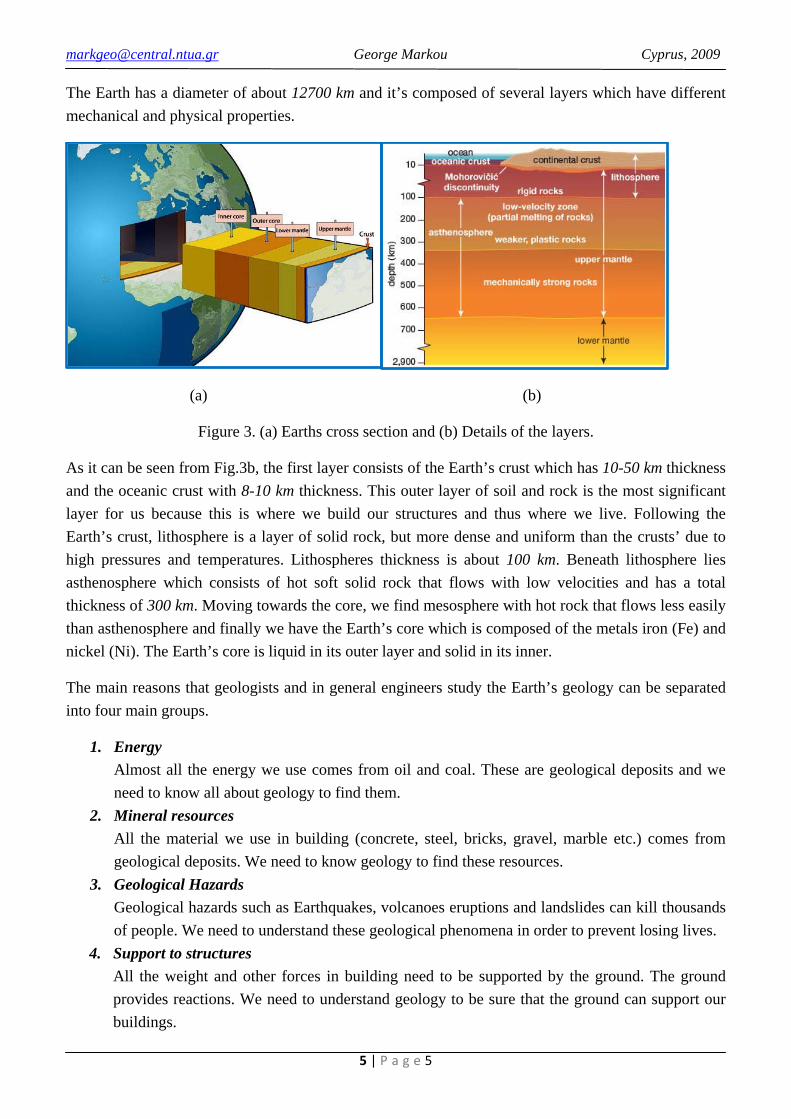
The Earth has a diameter of about 12700 km and it’s composed of several layers which have different mechanical and physical properties.
(a) (b)
Figure 3. (a) Earths cross section and (b) Details of the layers.
As it can be seen from Fig.3b, the first layer consists of the Earth’s crust which has 10-50 km thickness and the oceanic crust with 8-10 km thickness. This outer layer of soil and rock is the most significant layer for us because this is where we build our structures and thus where we live. Following the Earth’s crust, lithosphere is a layer of solid rock, but more dense and uniform than the crusts’ due to high pressures and temperatures. Lithospheres thickness is about 100 km. Beneath lithosphere lies asthenosphere which consists of hot soft solid rock that flows with low velocities and has a total thickness of 300 km. Moving towards the core, we find mesosphere with hot rock that flows less easily than asthenosphere and finally we have the Earth’s core which is composed of the metals iron (Fe) and nickel (Ni). The Earth’s core is liquid in its outer layer and solid in its inner.
The main reasons that geologists and in general engineers study the Earth’s geology can be separated into four main groups.
1. Energy Almost all the energy we use comes from oil and coal. These are geological deposits and we need to know all about geology to find them.
2. Mineral resources All the material we use in building (concrete, steel, bricks, gravel, marble etc.) comes from geological deposits. We need to know geology to find these resources.
3. Geological Hazards Geological hazards such as Earthquakes, volcanoes eruptions and landslides can kill thousands of people. We need to understand these geological phenomena in order to prevent losing lives.
4. Support to structures All the weight and other forces in building need to be supported by the ground. The ground provides reactions. We need to understand geology to be sure that the ground can support our buildings.

[email protected] George Markou Cyprus, 2009
6 | P a g e 6
3. Geology of Cyprus
All the rocks that we see around us were formed during these 4.6 billion years of which is the geological age of the Earth. The geology of Cyprus even though it’s complicated (Fig.4), is considered to be rather young, since the oldest geological composition located in the area of Pendedactylos mountains is up to 300 million years old (Paleozoic Era) while the rest of Cyprus is much younger. The Troodos mountains has been formed in stages over the past 60 million years and the island has its present shape for about the past 10 million years (early Tertiary Period).
Figure 4. Geological map of Cyprus.
Naming rocks and soil have been a difficult task. Often you will see one of the pre-mentioned geological periods included in the description of a rocks name. For example, the very white rock called Chalk that is found around Kochi, Lefkara and Petra tou Romiou was formed between 65 and 25 million years ago. Therefore, it is a rock from the Tertiary Period. The orange and grey rocks found in the Troodos area were formed 98 to 65 million years ago and so these are Cretaceous rocks.
The flat Mesaoria plain around Nicosia is formed of very recent material brought down from the mountains by rivers. These have been deposited only the last 2 million years, so these are known as Quaternary deposits.
Older rocks tend to be deeper and stronger, so the geological ages can help civil engineers identify rocks and estimate their properties.
[email protected] George Markou Cyprus, 2009
7 | P a g e 7
4. Minerals and Rocks
Theoretical geology, considers that rocks can be any kind of material that is located in the Earth’s crust and is composed of one or more minerals. In this sense, soil is also considered to be a rock but for civil engineers soil is characterized from its mechanical ability to break when a small mechanical force is applied (i.e. use of bare hands or immersion into water). Rock on the other hand, cannot be broken with bare hands and has higher mechanical properties.
When investigating the ground under, above or around a structure during its design process, all necessary information about its physical and chemical properties is required. These properties (including appearance) are determined basically from the minerals that compose each rock.
4.1 Minerals
Minerals are naturally occurring substances of different chemical compositions found in the Earth’s crust. There are approximately 5000 known minerals but the number of those which compose the crust’s rocks is about 30-35. Every mineral has its own unique chemical composition and therefore a unique name. Due to the fact that there are so many minerals, instead of being called by their chemical composition, they are all given names after their crystalline structures. For example, silicon dioxide (SiO2 διοξείδιο του πυριτίου) has different names, including quartz (χαλαζίας) and flint (πυριτικό ορυκτό), because of its different appearances and crystalline structure.
The identification of minerals is not always an easy task because their crystalline structure is affected from external factors. Civil engineers usually gather basic information about the minerals properties through the naked eye and if the identification of a mineral is impossible then the help of a geologist is required. There are several laboratory tests that can be conducted by the geologist in order to give a more specific answer about the minerals properties.
As we’ve said before, the mechanical, chemical and physical properties of a rock depends on the mineral composition. The mineral composition of a rock has a direct connection with the way that the rock was formed. Understanding the ways rocks form, it will significantly help to identify different rock types.
4.2 Rocks
There are three different types of rocks:
1. Igneous rocks (πυριγενή πετρώματα) 2. Metamorphic rocks (μεταμορφωμένα πετρώματα) 3. Sedimentary rocks (ιζηματογενή πετρώματα)
Each type has a certain way that it forms and which we are going to analyze in the following sections. The mechanical and hydraulic (underground water flow) properties of each rock, are determined form the way that a rock forms and the rocks geological history (erosion, depth etc).

[email protected] George Markou Cyprus, 2009
8 | P a g e 8
4.2.1 Igneous rocks Igneous rocks (πυριγενή πετρώματα) are solidified molten rocks (magma) derived from deep in the Earth’s crust or the upper mantle. They are mainly composed of silicate minerals and their mineralogy is affected by the rate of cooling due to different minerals crystallize at different temperatures. In addition to that, existing rock formations can get incorporated into igneous rock formations, affecting its composition.
Igneous rocks begin as magma. Intrusive igneous rocks, like granite (γρανίτης), form when magma cools inside the Earth. Extrusive igneous rocks, like the basalt lava flow in Fig.5, form at the Earth’s surface. Volcanic rocks are extrusive igneous rocks.
Figure 5. Hot magma from Hawaii's Kilauea Volcano.
Figure 6. Igneous rocks.
Igneous rocks as a foundation ground considers one of the best types, especially in cases where arc dams (τοξωτά φράγματα) are located or are going to be built. In the case of dams, we must be very careful with possible cracks due to seismic activity or erosion. If this is the case, then special measures must be taken in order to prevent underground water escape. The most used method in this case is the underground diaphragm made from cement and water.

[email protected] George Markou Cyprus, 2009
9 | P a g e 9
Intrusive formations Intrusive formations (πλουτωνικά πετρώματα) occur when the magma solidifies within Earth’s crust and they are divided between major and minor intrusions.
Major intrusions occur very deep in the Earth’s crust. About 95% of these formations are composed of granite. Minor intrusions penetrate through the Earth’s crust and can sometimes reach the surface. Dykes penetrate through layers of the existing rock at vertical or near vertical angles. They are usually a few meters wide and can reach up to hundreds of km long. They favor travelling along faults in the existing rock if they exist because penetration is easier. If they reach the surface they form a straight ridge in the existing rock. Sills are similar formations but are approximately horizontal. When forming, sedimentary rocks usually follow the existing direction of the rock’s bedding planes.
Extrusive formations Extrusive formations (ηφαιστιογενή πετρώματα) occur when magma erupts and solidifies at the surface. About 98% of these formations are composed of basalt (βασάλτης). These formations create volcanoes either on land or under the sea.
A Major Intrusion G Volcanic Pipe B Batholith H Volcano C Laccolith I Lava Flow D Magma J Cinder Cone E Dyke K Volcanic Neck F Minor Intrusion (Sill)
Figure 7. Igneous rock dtructures.
4.2.2 Metamorphic rocks Metamorphic rocks (μεταμορφωμένα πετρώματα) are igneous or sedimentary rocks (πυριγενή ή ιζηματογενή πετρώματα) that have been changed by heat or pressure. The minerals present in rocks are stable only up to a limited pressure and temperature. If these limits are exceeded then changes will occur in the mineralogy of a rock.
In metamorphism, nothing is added or taken away from the rock, except perhaps some water and carbon dioxide. Remember that metamorphism does not mean the melting of rock into magma – on solidification this would form new igneous rock. Metamorphism is divided between local and regional occurrences. Local metamorphism occurs around igneous inclusions, such as those shown in Figure 7, due to the heat generated in the existing rock in contact with them. Regional metamorphism occurs over hundreds or thousands of km when high confining pressures are imposed on large areas of rock.

[email protected] George Markou Cyprus, 2009
10 | P a g e 10
Regional metamorphism occurς when pressures of 2-3kbar and temperatures as high as 800°C which have been maintained for millions of years.
Some examples of metamorphism:
Clays, silts (άργιλος, ιλύς) Slate, phylite - (αργιλώδης σχιστόλιθος, φιλίτης)
Basic igneous rock (βασικά πυριγενή πετρώματα)
Schist (layered), serpentite (not layered) - (σχιστόλιθος με στρωμάτωση, σερπεντίτης
χωρίς στρωμάτωση)
Sand (άμμος) Quartzite (not layered) (χαλαζίτης χωρίς στρωμάτωση)
Limestone (ασβεστόλιθος) Marble (not layered) (μάρμαρο χωρίς στρωμάτωση)
4.2.3 Sedimentary rocks Sedimentary rocks (ιζηματογενή πετρώματα) are deposited on the Earth’s surface by water (sea, rivers, lakes), wind and ice. They form an outer skin on the Earth’s crust, covering about 75% of the continental areas and most of the sea floor but they compose only about 5% of the Earth’s crust. Sediment is any material that is transported and deposited somewhere on the Earth’s surface. It is useful to divide the sedimentary rocks between the three sources of their sediments.
Clastic sediments These sediments (κλαστικά πετρώματα) are derived from weathering and erosion of existing rocks. The sediments are transported from their parent rocks to other locations by wind, water, ice and gravity and then deposited at a new location. Wherever the sediment is deposited, it could be said that a new sedimentary rock has been formed. The clastic sediments are classified by the size of each particle. They are commonly divided into gravel, sand, silt and clay according to the particle sizes indicated below.
Figure 8. Clastic sediments classification according to their particle sizes.
A new deposit of sediment, say at the bottom of a river, will initially be loose or soft (like walking on soft sediment found in the sea or in a river). But as more sediment is deposited on top and diagenesis occurs (Table 2), the new deposit will become harder.

[email protected] George Markou Cyprus, 2009
11 | P a g e 11
Table 2. Diagenesis of sedimentary rocks. Original Sediment Increasing Diagenesis
Gravel (χαλίκι) Dense Gravel Interlocking, cementing Conglomerate (κροκαλοπαγές)
Sand (άμμος) Dense Sand Interlocking, cementing Sandstone (Ψαμμίτες)
Silt (ιλύς) Stiff Silt Hart Silt, cementing Siltstone (Ιλυόλιθος)
Clay (άργιλος) Stiff Clay Hart Clay, cementing Mudstone or shale (Αργιλικός σχιστόλιθος)
A civil engineer would call the original sediment and results of early diagenesis a “soil”, while the harder products of long term diagenesis would be called a “rock”.
Chemical sediments The most common chemical sediments are salt deposits left behind after evaporation of an inland sea or lake. Principal deposits are anhydrate (CaSO4), gypsum and common salt.
Organic sediments Organic sediments are derived from plants and animals. Limestones consist of animal and plant remains deposited in the sea. Chalk is a soft limestone composed mainly of the remains of algae. Coal and oil are also organic sediments.
Diagenesis As more layers of sediment are deposited above, pressure and temperature will increase. Especially if the water in the ground contains chemicals in solution, changes will take place. The particles of the sediment could be cemented together to form a rock. Burial to very big depths for millions of years could result in metamorphism.
Stratification of sediments One feature common to all sedimentary rocks is stratification (διαστρωμάτωση), because they are deposited and therefore they are all bedded or stratified (have layers). In many cases, sedimentary rocks will be deposited in horizontal layers and this would certainly be true at the bottom of a large mass of slow-moving waters.
Significance of sediments in civil engineering Sediments are an important source of fill material and of many raw materials, such as:
• Sand and gravel (for concrete) • Raw materials for cement • Aggregates for road construction • Clay (e.g. bentonite clay used in some construction works)
[email protected] George Markou Cyprus, 2009
12 | P a g e 12
• Masonry (limestones are particularly used) • Peat and coal • Gas, oil, bitumen • Gypsum (for plaster and a concrete additive) • Salts • Iron ores
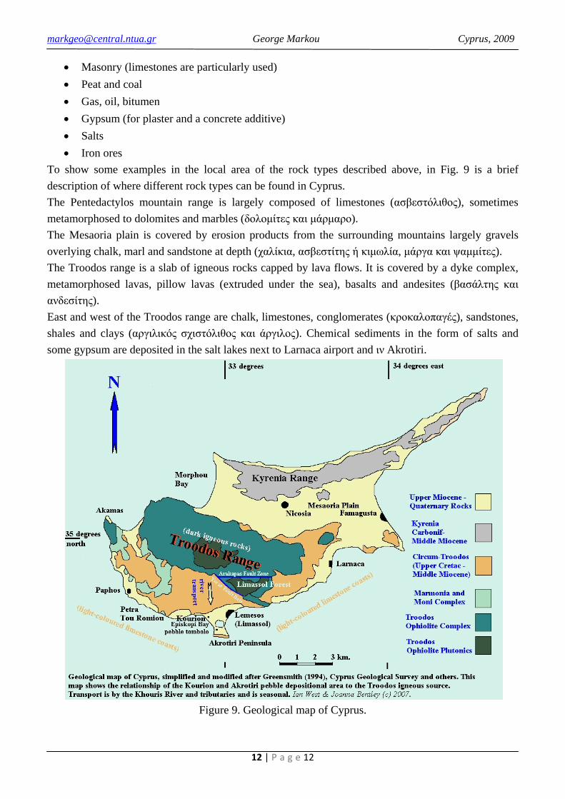
To show some examples in the local area of the rock types described above, in Fig. 9 is a brief description of where different rock types can be found in Cyprus. The Pentedactylos mountain range is largely composed of limestones (ασβεστόλιθος), sometimes metamorphosed to dolomites and marbles (δολομίτες και μάρμαρο). The Mesaoria plain is covered by erosion products from the surrounding mountains largely gravels overlying chalk, marl and sandstone at depth (χαλίκια, ασβεστίτης ή κιμωλία, μάργα και ψαμμίτες). The Troodos range is a slab of igneous rocks capped by lava flows. It is covered by a dyke complex, metamorphosed lavas, pillow lavas (extruded under the sea), basalts and andesites (βασάλτης και ανδεσίτης). East and west of the Troodos range are chalk, limestones, conglomerates (κροκαλοπαγές), sandstones, shales and clays (αργιλικός σχιστόλιθος και άργιλος). Chemical sediments in the form of salts and some gypsum are deposited in the salt lakes next to Larnaca airport and ιν Akrotiri.
Figure 9. Geological map of Cyprus.
[email protected] George Markou Cyprus, 2009
13 | P a g e 13
5. Earth Surface Processes
The surface of the Earth is changing through time. Material that is located close or on the Earth’s surface is constantly exposed to the weather and other natural phenomena like magma flow, active faultσ or a possible landslide area. As we’ve said already, one of the most important tools that civil engineers have for the interpretation of geological phenomenon, is the geological map. Through the knowledge of interpreting a geological map, we can draw various conclusions about the geological history of a site and of course recognize Earth surface processes. Nevertheless, we must always site investigate and conduct geological tests, especially for large scale structures that require ad hoc foundations (dams, bridge, high rise buildings etc).
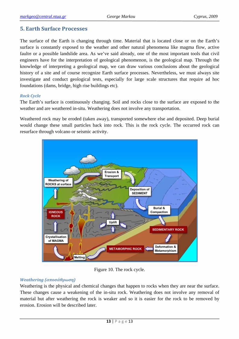
Rock Cycle The Earth’s surface is continuously changing. Soil and rocks close to the surface are exposed to the weather and are weathered in-situ. Weathering does not involve any transportation.
Weathered rock may be eroded (taken away), transported somewhere else and deposited. Deep burial would change these small particles back into rock. This is the rock cycle. The occurred rock can resurface through volcano or seismic activity.
Figure 10. The rock cycle.
Weathering (αποσάθρωση) Weathering is the physical and chemical changes that happen to rocks when they are near the surface. These changes cause a weakening of the in-situ rock. Weathering does not involve any removal of material but after weathering the rock is weaker and so it is easier for the rock to be removed by erosion. Erosion will be described later.

[email protected] George Markou Cyprus, 2009
14 | P a g e 14
Physical weathering (φυσική αποσάθρωση) • Stress relief: rocks open up at their joints because of the reduction in stress near the surface. • Freeze/thaw: when water in the rock becomes ice, it increases volume and pushes the rock
apart. • Temperature changes: rocks change volume when hot and cold which will slowly cause the
rock to break up. • Plants: plant roots help push rock apart.
Chemical weathering (χημική αποσάθρωση) Near the surface, rocks are exposed to water and air. This causes changes to the minerals in the rocks (e.g. oxidation, hydration, carbonation). Chemical weathering happens more quickly when water is present.
Changes to the minerals in the rocks usually cause an increase in volume and make the rock weaker.
Erosion, transport and deposition Erosion, transport and deposition are three more Earth surface processes. These can be caused by water (rivers or sea), wind or gravity.
Erosion (απογύμνωση) The removal of rock which has been weakened by weathering at the surface.
Transportation (μεταφορά) Movement of the eroded material away from its in-situ position.
Deposition (εναπόθεση) When transportation stops, the eroded material is left somewhere away from its in-situ position.

[email protected] George Markou Cyprus, 2009
15 | P a g e 15
6. Geological Hazards
In this chapter we are going to see the most common geological hazards and discuss their geological mechanisms. The most common geological hazards are:
1. Slope failure (κατολισθήσεις πρανών) 2. Earthquakes - faults (σεισμοί - ρήγματα) 3. Volcano eruptions (ηφαιστειακές εκρήξεις)
Geologists learned many things from geological disasters that occurred through time especially disasters that belong to the first two categories. At the end of this chapter we are going to describe two of the greatest geological disasters that happened due to the lack of geological site investigation and correct geological interpretation of the landscapes where the disasters took place.
6.1 Slope failure
Slope failure is the movement of a mass of rock or soil in the form of a slope due to gravity. The mass slides down a slope on a plane of failure in search of a new stability position. The loss of shear capacity is triggered because of several factors and the stability of a certain mass is breached.
Figure 11. Slope failure mechanisms.
Slopes fail when their angle is too big and gravity pulls the slope down. But a slope may have the same angle for years and then fail on one particular day.
Certain factors “trigger” the slope failure on a particular day. This could be one of the following:
1. A high level of groundwater in the slope which reduces the strength of the soil or weathered rock.
2. Failure of drainage to keep groundwater levels low. 3. Removal of plants and trees which helped to stabilize the slope and reduce groundwater levels. 4. Earthquakes. 5. Weight at the top of the slope, such as a new building or lorry. 6. Excavation at bottom of slope.

[email protected] George Markou Cyprus, 2009
16 | P a g e 16
7. Weakening of slope materials due to weathering (e.g. freeze-thaw action).
Slope failures can be controlled by several stabilizing techniques such as:
i. Re-profile the slope to reduce its slope angle. ii. Prevent some of the trigger mechanisms described above (drainage system, piles etc).
iii. Construct a support structure for the slope to stop it from failing.
6.2 Earhquakes
Large Earthquakes occur at plate boundaries where tectonic plates move relative to each other. The movements create stress in rock masses either side of a plate boundary which is released suddenly creating seismic waves (see Chapter 10).
Movement at one point on a plate boundary can create stress at other points on a plate boundary, giving foreshocks and aftershocks. In addition to that, waves that were created at one point of a plate’s boundary may collide to another plate boundary and create additional stresses activating in this way inactivated faults.
The seismic waves travel through the Earth’s crust from the focus (επίκεντρο) of the Earthquake. When the seismic waves pass through ground under a building, they cause the building to shake. The amount of damage depends on the magnitude of the Earthquake, the duration of the Earthquake and the response of the building. The magnitude is measured by the Richter scale which is a logarithmic scale based on the amplitude of the seismic waves.
The duration (length of time) of an Earthquake is one of the most important factors in the amount of damage a building will suffer.
Controlling earthquakes with physical means is humanly impossible because earthquake duration and magnitude cannot be predicted nor be stopped. Earthquake zones cover such a large area of the world, including Cyprus that it is impossible not to build in Earthquake zones. The only way to reduce loss of life due to Earthquakes is to study and understand them and to design Earthquake-resistant structures.
Design codes have been written for seismic-resistant structures in Earthquake zones. In Cyprus, the new Eurocode 8 for seismic design will shortly be introduced.
6.3 Volcanic eruptions
Volcanic eruptions occur at plate boundaries. There are also the Hawaiian volcanoes caused by hot spots beneath oceanic lithosphere.
Volcanic eruptions also cannot be controlled by man. The risk to man can only be reduced by predicting eruptions and allowing people to leave. It is quite easy to predict a volcanic eruption but it is very difficult to predict the size of an eruption. You can only move whole populations when there will be a large eruption because people will ignore you the next time if you move them for a little harmless eruption.

[email protected] George Markou Cyprus, 2009
17 | P a g e 17
6.4 Geological disaster of the Malpasset dam
One of the greatest geological disasters was the Malpasset dam in France (arc dam) which led to considerable loss of life. At 9:14 p.m. on December 2, 1959, the Malpasset dam failed explosively, giving rise to a flooding wave more than 40m high. Only a little portion of the arch of the dam still remained in its original position. 421 casualties were reported
Figure 12. Failure mechanism of Malpasset dam.
.
The geological mechanism that led to this disaster was caused from a “hidden” fault between the underground layers of the metamorphic rock beneath the dam’s foundation (Fig.12). The dam’s base moment initiated a vertical crack which propagated through the metamorphic rock beneath the dam’s foundation reaching the in-situ fault and creating a wedge of failure (Fig.12).
In order for this to happen, the geological condition of the rock was either not understood or not appreciated. The thin coal deposits were mixed with gray schists and shale, and with large areas of soft white flourite. The different types of rock had incompatible qualities, especially for a region with such weather extremes. Because of underfunding, the geological study of the rock was not thorough enough.
[email protected] George Markou Cyprus, 2009
18 | P a g e 18
Figure 13. Malpasset Dam after failure.
6.5 Geological disaster of the Vajont dam
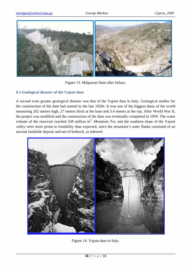
A second even greater geological disaster was that of the Vajont dam in Italy. Geological studies for the construction of the dam had started in the late 1920s. It was one of the biggest dams of the world measuring 262 metres high, 27 meters thick at the base and 3.4 meters at the top. After World War II, the project was modified and the construction of the dam was eventually completed in 1959. The water volume of the reservoir reached 168 million m3. Mountain Toc and the southern slope of the Vajont valley were more prone to instability than expected, since the mountain’s outer flanks consisted of an ancient landslide deposit and not of bedrock, as inferred.
Figure 14. Vajont dam in Italy.

[email protected] George Markou Cyprus, 2009
19 | P a g e 19
After the reservoir had been raised and lowered several times, the south margin of mountain Toc became eventually destabilized and after nearly three years of intermittent creeping, it catastrophically collapsed at 22:39 hours on 9th of October 1963. Within 30-40 seconds, some 270 million m3 of rock crashed into the reservoir, expelling a wave of 100-150m higher than the dam’s height.
The slide filled the valley and the reservoir causing a wave of water propagating both upstream and downstream. This wave reached maximum elevation of 935m which was 235m above the reservoir level (more than 100m above the dam’s level). It swept across the dam and the Vajont gorge and eventually fell onto Piave valley floor, where it destroyed the town Lorgarone and neighboring villages, killing 1909 lives. About 350 families were completely wiped away
Figure15. Failure mechanism of Vajont dam.
.
Figure 16. Landslide of Vajont dam.
The extraordinary of this geological disaster (except from the human losses) was that the Vajont dam did not fail. The estimated force from the gigantic wave was 9 times higher than the designed one but still it did not manage to destroy the dam. Of course nowadays, the dam is useless due to its reservoir

[email protected] George Markou Cyprus, 2009
20 | P a g e 20
destruction. Nevertheless, Italian government decided to declare the Vajont dam as a national monument and by repairing its minor damages, converted it into a tourist attraction area.
Figure 17. Map of landslide area of the Vajont dam.
Figure 18. Before and after failure (left and right respectively).

[email protected] George Markou Cyprus, 2009
21 | P a g e 21
7. Structural geology
Structural geology is the study of the three-dimensional distribution of rock units with respect to their deformational histories. The primary goal of structural geology is to use measurements of present-day rock geometries to uncover information about the history of deformation in the rocks.
In this chapter three of the basic geological deformation mechanisms are going to be analyzed. The first is called Faults (ρήγματα).
7.1 Faults
The outer part of the Earth is relatively hard and cold. So when it is stressed it tends to break, particularly if pushed quickly. These breaks, across which slip has occurred, are called faults (ρήγματα). The known phenomenon called Earthquake, occurs through this slippage procedure and if the fault is known to be active then it is call “an active fault” (ενεργό ρήγμα). These tend to happen along the boundaries between plates and that is where most of the active faulting occurs. But faulting can occur in the middle of the plates too, particularly in the continents.
There are three types of faults, a) Normal, b) Thrust and c) Strike-slip faults (ρήγματα κανονικά, ανάστροφα και πλάγιας ολίσθησης), as depicted in Fig. 19. Thus, it is obvious that any kind of fault combination can occur according to the plate’s deformation type.
Figure 19. Three basic fault types.
We must not here, that the produced Earthquake accelerograms are directly affected by the type of fault that creates them. This means for each type of fault we get different types of Earthquake signals.
[email protected] George Markou Cyprus, 2009
22 | P a g e 22
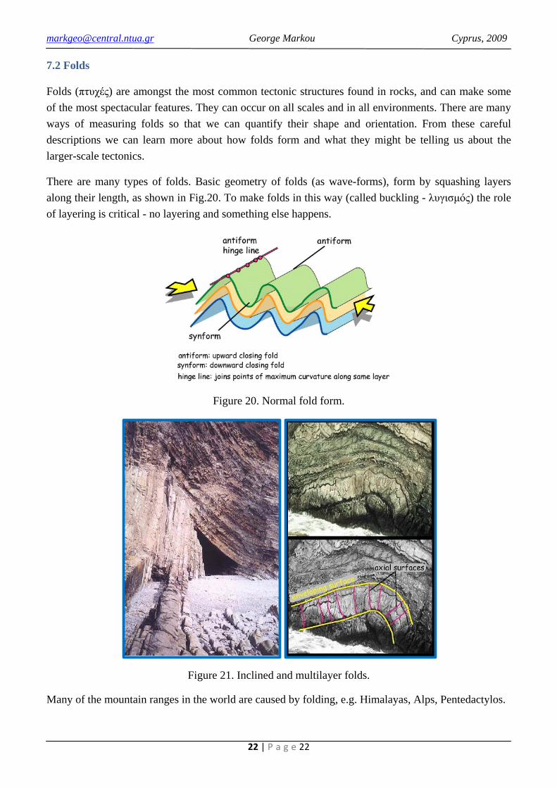
7.2 Folds
Folds (πτυχές) are amongst the most common tectonic structures found in rocks, and can make some of the most spectacular features. They can occur on all scales and in all environments. There are many ways of measuring folds so that we can quantify their shape and orientation. From these careful descriptions we can learn more about how folds form and what they might be telling us about the larger-scale tectonics.
There are many types of folds. Basic geometry of folds (as wave-forms), form by squashing layers along their length, as shown in Fig.20. To make folds in this way (called buckling - λυγισμός) the role of layering is critical - no layering and something else happens.
Figure 20. Normal fold form.
Figure 21. Inclined and multilayer folds.
Many of the mountain ranges in the world are caused by folding, e.g. Himalayas, Alps, Pentedactylos.

[email protected] George Markou Cyprus, 2009
23 | P a g e 23
7.3 Strain (Distortion)
If not layered (igneous and metamorphic rocks), the crust could simply compress, or strain. If a rock has no layering and is simply homogeneous (rather like a pat of butter), if it's squeezed it will just thicken up. You can quantify the amount of strain by tracking how the butter pat becomes thick or less wide. If you stamp a circle on the surface of the butter and then distort it, notice that the circle becomes an ellipse. In strata originally circular markers will become ellipses as the rock strains too. This is also a way in which the amount of strain can be charted.
Figure 22. Homogenous distortion.
Figure 23. Distorted, originally sub-circular markers now with elliptical shapes. Deformed oncoliths, Haut Giffre area, French Alps.

[email protected] George Markou Cyprus, 2009
24 | P a g e 24
8. Ground water
Ground water is water that is mostly underground. It occupies the pore spaces in between the individual grains of soil and rock. A large percentage of the world's drinking water comes from this source. People in rural areas have wells that are drilled through the ground down to the water table. A large number of jobs in geology have to do with ground water, as people need fresh water for drinking.
Figure 24. Porosity.
Porosity is the percentage of the volume of the rock that is open space (pore space). This determines the amount of water that a rock can contain.
Figure 25. Groundwater.
Rain that falls on the surface seeps down through the soil and into a zone called the zone of aeration or unsaturated zone where most of the pore spaces are filled with air. As it penetrates deeper it eventually enters a zone where all pore spaces and fractures are filled with water. This zone is called the saturated zone. The surface below which all openings in the rock are filled with water (the top of the saturated zone) is called the water table.
In more humid regions it reaches the surface at streams and lakes, and generally tends to follow surface topography. The depth to the water table may change, as the amount of water flowing into and out of the saturated zone changes. During dry seasons, the depth to the water table increases. During
[email protected] George Markou Cyprus, 2009
25 | P a g e 25
wet seasons, the depth to the water table decreases. If there is no rain for a long time, like the case of Cyprus, then the groundwater table decreases rapidly due to extensive use of wells resulting having to be dug to deeper levels.
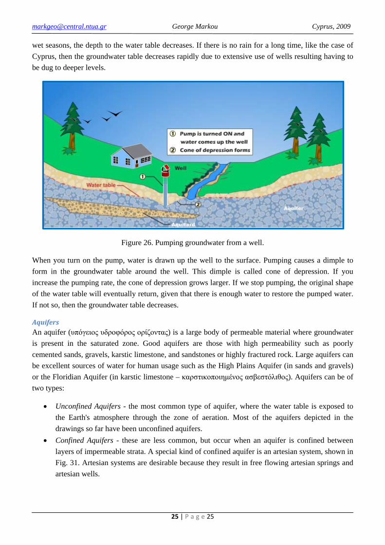
Figure 26. Pumping groundwater from a well.
When you turn on the pump, water is drawn up the well to the surface. Pumping causes a dimple to form in the groundwater table around the well. This dimple is called cone of depression. If you increase the pumping rate, the cone of depression grows larger. If we stop pumping, the original shape of the water table will eventually return, given that there is enough water to restore the pumped water. If not so, then the groundwater table decreases.
Aquifers An aquifer (υπόγειος υδροφόρος ορίζοντας) is a large body of permeable material where groundwater is present in the saturated zone. Good aquifers are those with high permeability such as poorly cemented sands, gravels, karstic limestone, and sandstones or highly fractured rock. Large aquifers can be excellent sources of water for human usage such as the High Plains Aquifer (in sands and gravels) or the Floridian Aquifer (in karstic limestone – καρστικοποιημένος ασβεστόλιθος). Aquifers can be of two types:
• Unconfined Aquifers - the most common type of aquifer, where the water table is exposed to the Earth's atmosphere through the zone of aeration. Most of the aquifers depicted in the drawings so far have been unconfined aquifers.
• Confined Aquifers - these are less common, but occur when an aquifer is confined between layers of impermeable strata. A special kind of confined aquifer is an artesian system, shown in Fig. 31. Artesian systems are desirable because they result in free flowing artesian springs and artesian wells.

[email protected] George Markou Cyprus, 2009
26 | P a g e 26
Volume changes due to groundwater If the groundwater table rises (usually because of a lot of rain) the soil or rock increases in volume (or swells – αύξηση όγκου ή «πρήξιμο»). This causes heave which is a rise in the level of the ground surface (Figs. 27 - 28).
If the groundwater table falls (usually because of a long period without rain) the soil or rock decreases in volume (or shrinks - συρρίκνωση). This causes subsidence which is a fall in the level of the ground surface (Figs. 27 - 28).
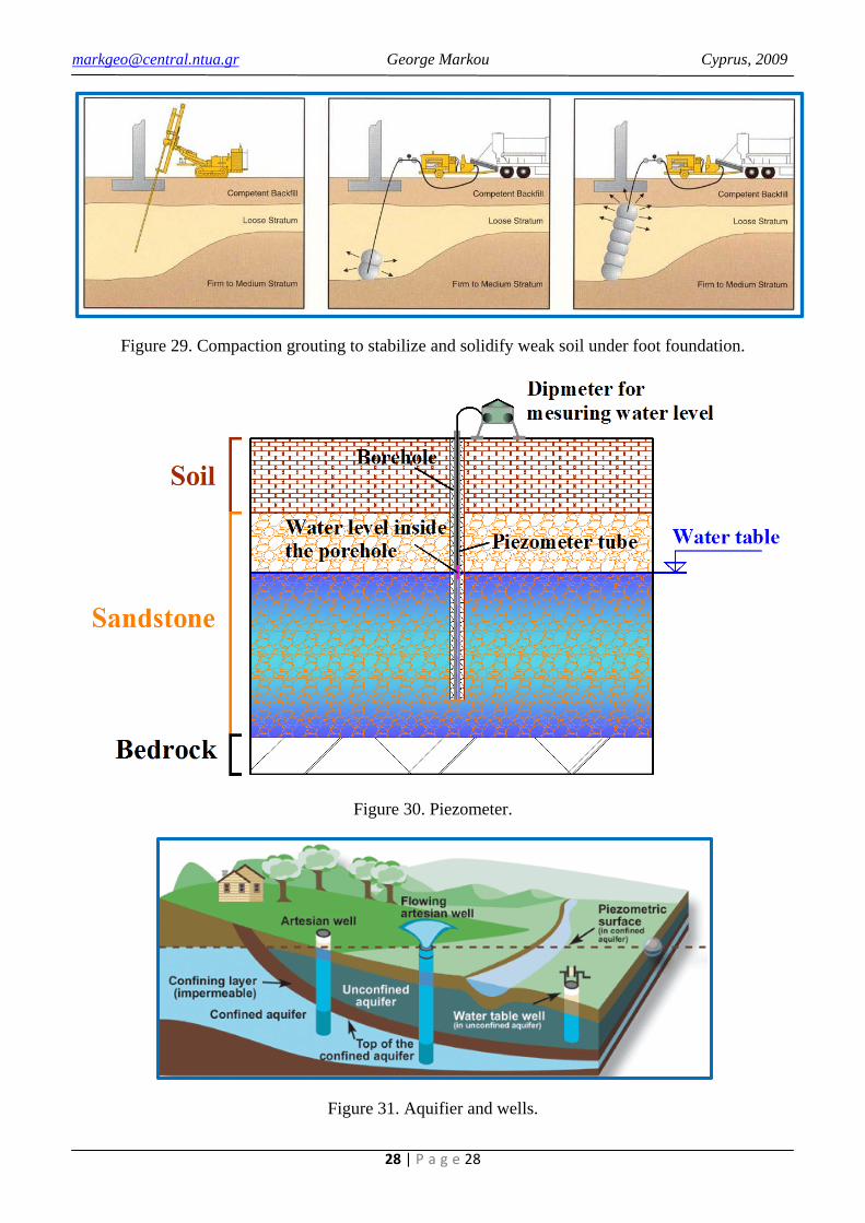
Heave and subsidence (διόγκωση και καθίζηση εδάφους) can damage a building as shown in Fig. 27. It is therefore important that the groundwater table level is measured in a hydrogeological investigation and if necessary create some anti-measure system in order to prevent this geological phenomenon (concrete piles (Fig. 1b), compaction grouting (Fig. 29), drainage system etc).
Figure 27. Building damages due to Heave and Subsidense.
Hydrogeological investigations Hydrogeology (υδρογεωλογία) is a science which deals with groundwater, based on investigations of phenomena and processes related to the occurrence and migration of groundwater, as well as studies of mutual interactions between the rock and the water.
The normal method of investigation is to install plastic tubes called piezometers into boreholes which have been dug as part of a site investigation (Fig. 30). The water level in the tube is measured with a dipmeter over several days, weeks or months during different weather conditions and seasons to monitor the level of the water table.

[email protected] George Markou Cyprus, 2009
27 | P a g e 27
Figure 28. Volum
e changes due to rise and fall of groundwater table.
[email protected] George Markou Cyprus, 2009
28 | P a g e 28
Figure 29. Compaction grouting to stabilize and solidify weak soil under foot foundation.
Figure 30. Piezometer.
Figure 31. Aquifier and wells.

[email protected] George Markou Cyprus, 2009
29 | P a g e 29
9. Site Investigations
The geology under a site cannot be chosen like the steel or concrete in the structure. It is already there long before the project starts and we need to go and find out what rocks and soil exist under the site. This process of learning what exists under the site is called Site Investigation.
Why site investigations needed? 1. A site investigation helps to decide if a site is suitable for a proposed development. This
decision is mostly based on the cost of construction. A site investigation will show if the site will be expensive to use (perhaps because of a geological hazard such as landslides or because the ground is very weak). It is better to learn about geological problems before you start construction so that you can plan for them or not even use the site.
2. A site investigation is also required to design the structure. We need to know the geology to design foundations, basements, roads and to design against landslides, Earthquakes, flooding and other hazards.
The stages of a site investigation are:
1. Desk Study (a study of the information already available). 2. Sub-surface investigation. 3. In-situ testing. 4. Laboratory testing. 5. Report writing. 6. Monitoring.
Each of these stages is described below.
Desk Study In a Desk Study we look for information about the site that is already available before starting the sub-surface investigation. There are three advantages to doing a Desk Study:
a) the information is usually cheap and for towns and cities there is usually a lot of information available from nearby sites.
b) the information from the Desk Study helps to plan the sub-surface investigation and to use the best investigation methods.
c) the information from the Desk Study helps to understand the results of the sub-surface investigation and to write the report.
Information for the Desk Study can be obtained from: Geological maps and books: usually published by a government department. They help you to predict the general geology in the area of your site which helps you to plan your sub-surface investigation. Each map or book costs about €17 (£10). Topographical maps (present and historical): also published by government departments. They show the shape of the ground surface, rivers, beaches, buildings, quarries, etc. You might be able to see a

[email protected] George Markou Cyprus, 2009
30 | P a g e 30
hazard such as a landslide on a topographical map. Historical maps may show you a hazard such as an old quarry which has since been covered over and cannot be seen today. Each map costs about €17 (£10). Aerial photographs (present and historical): photographs taken off the ground from aeroplanes. These provide similar information to topographical maps. Low quality photographs are available free on the internet, high quality photographs are available from companies for about £20 each. Previous site investigation report: it is possible that a site investigation has already been done on the site, 1 year ago? 10 years ago? The site investigation company may sell you a copy for about €1700 (£1000) so that you don’t need to spend around €34000 (£20.000) on another sub-surface investigation. Site walkover
Sub-surface investigation
: we walk over the site and note down where possible the rock types, shape of land surface, geological hazards. We can also plan the sub-surface investigation at this time.
The objective of the sub-surface investigation is to learn the specific geology under the site. We make holes in the ground and bring the rocks or soil up to the surface in order to look at them and describe them. The rocks or soil we bring to the surface are called samples. The location of the holes depends on the shape and size of the structure. The number of holes depends on the amount of uncertainty and variability in the geology as found in the Desk Study (uncertain or variable geology requires many holes, certain and non-variable geology requires few holes). The depth of the holes depends on how deep the new structure will cause stress change in the ground. Types of holes for sub-surface investigation:
I) Trial pits
II)
: these are easily and cheaply dug by excavator to about 3m depth. They give a large view of the geology but only to shallow depth. Samples can be taken for laboratory testing. Boreholes, cable percussion method
III)
: can be used in soils and soft rocks. Holes of 150mm or 200mm diameter are made up to 60m depth. Heavy tools at the end of a cable are dropped into the hole to collect soil or rock and bring it to the surface. Boreholes, rotary drilling method
In-situ testing
: are used for hard rocks. A tube with a cutting end is rotated and pushed into the ground. The tube is pulled out and a continuous cylinder of rock is obtained (called a rock core). The cores can be any diameter from 18mm to 160mm and can be used for description or laboratory testing.
The engineering properties (e.g. strength) of soil or rock under a site can either be tested while it is in-situ or on samples taken to a laboratory. Advantages of in-situ testing: a) the soil or rock is not disturbed by bringing it to the surface and taking it to a laboratory and b) the soil or rock is being tested in its natural state in the ground.

[email protected] George Markou Cyprus, 2009
31 | P a g e 31
Disadvantage of in-situ testing: the test cannot be precisely controlled and measured like in the laboratory. Because of these advantages and disadvantages, for most site investigations a combination of in-situ and laboratory testing is carried out. Standard penetration test (SPT) The most common in-situ test on soil is the standard penetration test (SPT). A cone is driven into the ground by a hammer. The number of hits ‘N’ of the hammer needed to drive the cone 300mm into the ground is counted. The strength of the soil can be estimated because stronger soil needs higher N to drive the cone 300mm into it and weaker soil needs a smaller N.
Laboratory testing
Other in-situ tests There are many other types in-situ tests. These include the Dutch cone penetration test (CPT) which is similar to SPT but uses a static load to push the cone into the ground. A shear vane is used to test the strength of soft soils in trial pits or boreholes. A pressuremeter measures the horizontal stiffness and strength of soils in a borehole. Small plate loading tests measure the strength and stiffness of a soil at the bottom of a borehole. Large plate loading tests measure the strength and stiffness of a soil near the surface in a trial pit.
As described above, the advantage of laboratory testing is that precise control and measurement of tests is possible. The difficult job is to bring the soil or rock samples to the surface and to the laboratory without changing (or disturbing) them. A sample that is brought to the surface with the same structure as in the ground is called an undisturbed sample. These are difficult to obtain, particularly for sand and gravel. Undisturbed samples are needed to measure strength and density. Rock cores are a type of undisturbed sample. A sample that is brought to the surface but with its structure destroyed is called a disturbed sample. These are less useful but you can measure some properties like particle size and water content.
Report writing A lot of information comes from a site investigation and it will be needed by a lot of people (e.g. Developer, Civil Engineers, Contractors, archaeologists, government licensing authorities). The information needs to be brought together into a report in a way that will be understood by people who are not experts in Geology.
Monitoring We cannot investigate every piece of rock under a site. During the site investigation we dig some holes to see and test the rocks. But there is a lot of soil and rock in between the holes which we never see. It might be stronger or weaker than the soil and rocks we found in our holes. We have to assume the same soil and rocks exist between the holes, but maybe it doesn’t? Whatever assumption we make, there is a risk that we are wrong. We therefore have to check our assumptions by monitoring. During construction, we check any holes that are dug on the site to see that the soil and rocks are the same as we assumed in our site investigation. And during and after construction we check that the foundations and walls of the building are not moving more than we predicted in our design. If the foundations or walls are moving more than we

[email protected] George Markou Cyprus, 2009
32 | P a g e 32
predicted, this means that the soil or rocks under the site are not as strong as we assumed and we might need to do more construction work before the building is finished.

[email protected] George Markou Cyprus, 2009
33 | P a g e 33
10. Plate tectonics
Plate tectonics (from Greek «τέκτων» which means "builder" or "mason") describes the large scale motions of Earth's lithosphere. As we’ve said in Chapter 2, the outermost section of the Earth's interior is made up of two layers: above is the lithosphere, comprising the crust and the rigid uppermost part of the mantle. Below the lithosphere lies the asthenosphere. Although solid, the asthenosphere has relatively low viscosity and shear strength and can flow like a liquid on geological time scales. The deeper mantle below the asthenosphere is more rigid again due to the higher pressure.
The lithosphere is broken up into what is called tectonic plates — in the case of the Earth, there are seven major and many minor plates (Fig. 32). These plates move in relation to one another at one of three types of plate boundaries: convergent or collision boundaries, divergent or spreading boundaries, and transform boundaries. Earthquakes, volcanic activity, mountain-building, and oceanic trench formation occur along plate boundaries. The lateral movement of the plates is typically at speeds of 50—100 mm annually.
As you can see from Fig. 32, Cyprus belongs in Eurasian plate and is located near the boundary of Eurasian, Arabian and African plates making the island seismically active. The need for seismically resistance structures is obvious and this can be achieved through the understanding of structural mechanics, soil-structure interaction and the geological response during an Earthquake.
Figure 32. Earth’s Tectonic Plates.

[email protected] George Markou Cyprus, 2009
34 | P a g e 34
Divergent plate boundaries Divergent plate boundaries occur where two plates move away from each other. These generally occur at oceanic ridges where new oceanic lithosphere and crust is being formed (Fig. 33). A well-known example is the mid-Atlantic ridge. Convergent plate boundaries Convergent plate boundaries occur where two plates move towards each other (Fig. 33). These can occur between oceanic plates, continental plates or between oceanic and continental plates, as shown in the figure below. One plate is forced below the other and the extreme heat and pressure melts the crust and lithosphere to form magma. The magma rises through the upper plate to form volcanoes. One example of this type of boundary is in Indonesia which caused the Asian tsunami in December 2004. Transform plate boundaries Transform plate boundaries occur when two plates slide past each other horizontally (Fig. 33). These might occur within convergent or divergent plate boundaries. The San Andreas plate boundary in San Francisco is a transform plate boundary.
Figure 33. Three types of tectonic plate boundaries.
Earthquakes Although plates would like to move at about the same speed as our fingernails grow, often the friction at plate boundaries prevents the movement and this causes stress to increase at the plate boundaries. Eventually the stress is too big for the friction and there is movement at the plate boundary. Years’ of movement may be released in a few seconds, perhaps a meter or more. This sudden large movement causes Earthquakes.
Types of Earthquakes There are many different types of Earthquakes: tectonic, volcanic, explosion and slope failure. The type of Earthquake depends on the region where it occurs and the geological characteristics of that region. The most common are tectonic Earthquakes. These occur when rocks in the Earth's crust break

[email protected] George Markou Cyprus, 2009
35 | P a g e 35
due to geological forces created by movement of tectonic plates. Another type, volcanic Earthquakes, occurs in conjunction with volcanic activity. Explosion Earthquakes result from the explosion of nuclear and chemical devices. The creation of an Earthquake due to a slope failure is very rare. The seismic wave occurs because of the friction between a large sliding volume of rock with the bedrock (i.e. Vajont dam slope failure).
Types of Earthquake waves Earthquake shaking and damage is the result of three basic types of elastic waves. Two of the three propagate within a body of rock. The faster of these body waves is called the primary or P wave. Its motion is the same as that of a sound wave; it alternately pushes (compresses) and pulls (dilates) the rock. These P waves are able to travel through both solid rock, such as granite mountains, and liquid material, such as volcanic magma or the water of the oceans.
The slower wave through the body of rock is called the secondary or S wave. As an S wave propagates, it shears the rock sideways at right angles to the direction of travel. S waves cannot propagate in the liquid parts of the Earth, such as oceans and lakes because they have no shear capacity.
The actual speed of P and S seismic waves depends on the density and elastic properties of the rocks and soil through which they pass. In most Earthquakes, the P waves are felt first. Some seconds later, the S waves arrive with their up-and-down and side-to-side motion, shaking the ground surface vertically and horizontally. This is the wave motion that is so damaging to structures. The third general type of Earthquake wave is called a surface wave. Surface waves in Earthquakes can be divided into two types. The first is called a Love wave. Its motion is essentially that of S waves that

[email protected] George Markou Cyprus, 2009
36 | P a g e 36
have no vertical displacement; it moves the ground from side to side in a horizontal plane but at right angles to the direction of propagation.
The second type of surface wave is known as a Rayleigh wave. Like rolling ocean waves, Rayleigh waves wave move both vertically and horizontally in a vertical plane pointed in the direction in which the waves are travelling.
Surface waves travel slower than body waves (P and S); and of the two surface waves, Love waves generally travel faster than Rayleigh waves. Love waves (do not propagate through water) can effect surface water only insofar as the sides of lakes and ocean bays pushing water sideways like the sides of a vibrating tank, whereas Rayleigh waves, because of their vertical component of their motion can affect the bodies of water such as lakes.

[email protected] George Markou Cyprus, 2009
37 | P a g e 37
11. Geological Maps and Geological Sections
Topographic maps are made to illustrate as better as possible, in a 2D plane, the image of the Earth’s surface. In technical geology, the ability of reading correctly a topographical map and analyzing it gives us the ability to recognize geological features and discover geological phenomenon that may play an important role (positive or negative) for the construction or not, of our structures. For example, from a correct reading it can be extrapolated whether a change of the petro graphic components is present or a sudden change in the surface slope exists (slope slide) etc. Nevertheless, site investigation cannot be put aside and always must be contacted in order to validate our findings from the map analysis.
Geological maps are topographic maps which include the geological features of the Earth’s surface. All maps have three basic features:
1. System of direction. North – East – South – West. We have three different types of North direction. The cartographical North, the geographical North and the magnetic North.
2. The scale of the map which express the distance measured on the map corresponding to the real distance. We have several scale factors according to the study at hand:
• 1:1000 or 1:500 for a dam’s foundation. • 1:5000 for a dam’s reservoir. • 1:1000, 1:500 or 1:200 for a foundation or slope slide. • 1:5000 or 1:10000 for a tunnel. • 1:5000, 1:10000 or 1:20000 for transportation structures. • 1:5000 – 1:20000 for hydrological structures.
3. Contour lines.
Reading a map Map reading is nothing else but the interpretation of its data which includes the map’s direction, geographic location, contour lines and symbolization. The main goal of the topographic map is to illustrate the Earth’s surface anaglyph. This is also its main use in order to use it for geological and structural purposes.
Fig. 34 shows the way contour lines are created for a simple hill that has a total height of H meters. We choose a certain contour interval d (difference in elevation between two adjacent contours) and cutting the hill’s surface with the help of horizontal planes, at elevations H1, H2 and H3, respectively. The incision lines that occur through this process are called contour lines. The elevation of a contour line
Contour lines
The surface of the Earth is described by the contour lines which are continuing points that have the same elevation which means that all points that lie on a specific contour line of a map, have the same elevation. This can be translated as the section of the topographic surface with a horizontal plane of a given elevation (Fig. 34).

[email protected] George Markou Cyprus, 2009
38 | P a g e 38
represents the vertical height of the contour line from the surface level of the sea. It means that if we read in a map that a certain contour line has elevation 100m, it follows that all points located on that contour line are 100m above than the surface of the sea.
Figure 34. Creating contour lines.
Figure 35. Correlation between the contour lines of a map and the 3D anaglyph of the Earth’s surface.
[email protected] George Markou Cyprus, 2009
39 | P a g e 39
Fig. 35 shows the correlation between map’s contour lines and the 3D anaglyph of a certain area that has been chosen to be maped. As we can see, the map’s contour interval is equal to 20m and the landscape consists of several geological characteristics and features like: mountains, a river, streams, a coastline, geological material from debris slide, dense contour lines that indicate a cliff and therefore healthy rock etc.
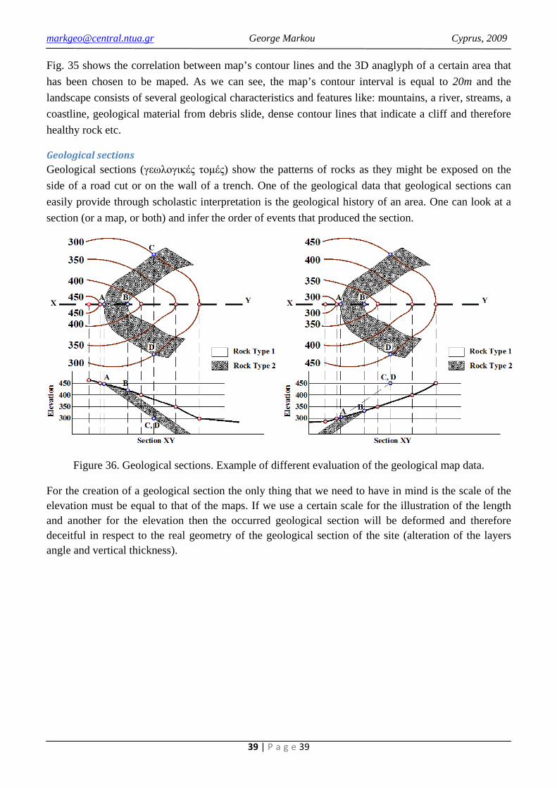
Geological sections Geological sections (γεωλογικές τομές) show the patterns of rocks as they might be exposed on the side of a road cut or on the wall of a trench. One of the geological data that geological sections can easily provide through scholastic interpretation is the geological history of an area. One can look at a section (or a map, or both) and infer the order of events that produced the section.
Figure 36. Geological sections. Example of different evaluation of the geological map data.
For the creation of a geological section the only thing that we need to have in mind is the scale of the elevation must be equal to that of the maps. If we use a certain scale for the illustration of the length and another for the elevation then the occurred geological section will be deformed and therefore deceitful in respect to the real geometry of the geological section of the site (alteration of the layers angle and vertical thickness).