geometric design of existing freeway (3r) or (4r) … department of transportation—2013 design...
TRANSCRIPT
INDIANA DEPARTMENT OF TRANSPORTATION—2013 DESIGN MANUAL
CHAPTER 54
Geometric Design of Existing Freeway (3R) or (4R) Partial
Reconstruction
Design
Memorandum Revision
Date Sections Affected
13-01 Jan. 2013 Figure 54-6B(70)
NOTE: This chapter is currently being re-written and its content will be included in Chapter 302 in the future.
Page 2 2013 Indiana Design Manual, Ch. 54
TABLE OF CONTENTS
LIST OF FIGURES ........................................................................................................................ 3
54-1.0 GENERAL .......................................................................................................................... 4
54-1.01 Background ................................................................................................................... 4
54-1.02 Applicability ................................................................................................................. 4
54-1.02(01) Freeway Definition ............................................................................................ 4
54-1.02(02) Project Scope of Work ....................................................................................... 5
54-1.03 Objectives ..................................................................................................................... 6
54-1.04 Approach ...................................................................................................................... 7
54-1.05 3R or Partial 4R Project Evaluation ............................................................................. 8
54-2.0 TABLE OF 3R OR PARTIAL 4R FREEWAY GEOMETRIC-DESIGN VALUES ...... 10
54-3.0 GEOMETRIC DESIGN ................................................................................................... 11
54-3.01 Design Controls .......................................................................................................... 11
54-3.01(01) Traffic-Volume Analysis ................................................................................. 11
54-3.01(02) Design Speed ................................................................................................... 12
54-3.02 Horizontal and Vertical Alignment ............................................................................ 12
54-3.02(01) Superelevation .................................................................................................. 12
54-3.02(02) Grades .............................................................................................................. 13
54-3.02(03) Vertical Clearance ............................................................................................ 13
54-3.03 Cross Section .............................................................................................................. 13
54-3.03(01) Lane and Shoulder Width ................................................................................ 13
54-3.03(02) Curbs ................................................................................................................ 13
54-3.03(03) Median ............................................................................................................. 14
54-3.03(04) Fill or Cut Slope ............................................................................................... 14
54-3.03(05) Right of Way .................................................................................................... 15
54-3.03(06) Interchange ....................................................................................................... 15
54-4.0 ROADSIDE SAFETY ...................................................................................................... 16
54-5.0 BRIDGES ......................................................................................................................... 16
54-5.01 General ....................................................................................................................... 16
54-5.02 Bridge To Remain In Place ........................................................................................ 17
54-6.0 MEDIAN OPENING ........................................................................................................ 17
54-6.01 Guidelines ................................................................................................................... 17
54-6.02 Implementation ........................................................................................................... 18
54-6.03 Design ......................................................................................................................... 18
54-6.04 Location of Interstate-Route Crossover ..................................................................... 19
FIGURES ...................................................................................................................................... 20
2013 Indiana Design Manual, Ch. 54 Page 3
LIST OF FIGURES Figure Title 54-2A Geometric Design Criteria for Freeways (3R / Partial 4R Projects) 54-3A Lengths for Deceleration 54-3B Grade Adjustments for Deceleration 54-6A Barrier Treatment at a Median Crossover 54-6B(64) Interstate-Route Crossovers, I-64 54-6B(65) Interstate-Route Crossovers, I-65 54-6B(69) Interstate-Route Crossovers, I-69 54-6B(70) Interstate-Route Crossovers, I-70 [Rev. Jan. 2013] 54-6B(74) Interstate-Route Crossovers, I-74 54-6B(94) Interstate-Route Crossovers, I-94 54-6B(100) Interstate-Route Crossovers, Three-Digit-Numbered Routes
Page 4 2013 Indiana Design Manual, Ch. 54
CHAPTER 54
GEOMETRIC DESIGN OF EXISTING
FREEWAY (3R) OR (4R)
PARTIAL RECONSTRUCTION
54-1.0 GENERAL
54-1.01 Background
The Department began construction of its freeway system in the 1950s, and today the Indiana system
has been completed. The freeway system has introduced a level of mobility and safety for the
traveling public which was unattainable without its special features, such as full control of access,
wide roadway widths, and higher design speeds.
The freeway system requires periodic repair and upgrading which exceeds the limits of normal
maintenance. Such a capital improvement is defined as a 3R project (resurfacing, restoration, and
rehabilitation), partial-reconstruction (4R) project, or full-reconstruction (4R) project. This Chapter
discusses the Department’s design criteria for a 3R or partial 4R reconstruction project on a freeway.
These criteria meet or exceed the criteria described in AASHTO’s A Policy on Design Standards -
Interstate System and AASHTO’s A Policy on Geometric Design of Highways and Streets. A full-
reconstruction project should be designed in accordance with the criteria described elsewhere in this
Manual.
54-1.02 Applicability
54-1.02(01) Freeway Definition
Within the functional-classification system, a freeway is the highest level of arterial. Such a facility
is characterized by full control of access, divided roadways, high design speed, and a high level of
driver comfort and safety. Each Interstate highway as well as any other route with full control of
access is classified as a freeway (e.g., US 31 around South Bend, SR 912 in Lake County, Airport
Expressway in Indianapolis). See Section 40-1.0 for more information on the functional-
classification system and the role of the freeway within the system.
2013 Indiana Design Manual, Ch. 54 Page 5
54-1.02(02) Project Scope of Work
Section 40-6.01 defines the typical types of improvements that are made on a 3R or reconstruction
project on the National Highway System (NHS). The following provides an overview of what may
represent a 3R freeway project or a freeway reconstruction project. For a more in-depth description,
the designer should review Section 40-6.01. For a freeway, the distinction between 3R, partial
reconstruction, and complete reconstruction can be summarized as follows:
1. 3R Project. A 3R freeway project may include the improvements as follows:
a. pavement resurfacing;
b. full-depth pavement reconstruction, if the reconstructed pavement area is 30% or less
of the traveled way;
c. widening existing travel lanes or shoulders;
d. upgrading the structural strength of shoulders;
e. improving the superelevation of existing horizontal curves;
f. adding auxiliary lanes;
g. improving roadway delineation;
h. upgrading roadside safety;
i. increasing the length of acceleration and deceleration lanes at an interchange;
j. widening an existing bridge as part of a bridge reconstruction project;
k. upgrading or replacing bridge railings;
l. overlaying bridge decks;
m. preservation of bridge substructures;
n. improving roadside drainage;
o. widening existing ramps;
Page 6 2013 Indiana Design Manual, Ch. 54
p. flattening horizontal or vertical curves; or
q. increasing the vertical clearance at underpasses.
2. Partial-Reconstruction (4R) Project. A partial-reconstruction (4R) freeway project may
include the improvements as follows:
a. more than 30% of the travelway pavement area must be removed and replaced,
b. a concrete overlay of a least 6 in. is required, or an asphalt overlay of at least 8 in. is
to be placed;
c. the facility cannot adequately accommodate the current or projected (10-year) traffic
demand and additional lanes are necessary;
d. major revisions are necessary to the existing horizontal and vertical alignment
requiring that more than 30% of the travelway pavement must be replaced;
e. total bridge or bridge-deck replacement is required;
f. bridge-deck widening is necessary due to added travel lanes on the approaches; or
g. interchange upgrading is required to meet current and projected (20-year) traffic
demands.
3. Complete-Reconstruction (4R) Project. A freeway improvement is considered to be a
complete reconstruction if the project intent is to replace the existing facility. Complete
reconstruction will typically provide significant improvements in level of service,
operational efficiency, and safety. For a complete-reconstruction project, the criteria
described in Chapter 53 should be used.
54-1.03 Objectives
The basic objective of a 3R/partial 4R freeway project is to improve the freeway’s serviceability to
meet future demands by extending the service life of the existing facility and enhancing highway
safety. This objective applies to all aspects of the freeway’s serviceability. If a project is classified
as a partial 4R project, an additional objective, where practical, is to upgrade existing elements to
2013 Indiana Design Manual, Ch. 54 Page 7
new-construction criteria. For example, where the pavement is to be replaced, it may be practical to
improve the horizontal or vertical alignment.
54-1.04 Approach
A 3R/Partial 4R freeway project is most-often initiated to make a specific improvement to the
freeway (e.g., resurfacing or roadside-safety improvements). The Department’s policy is to review
and upgrade other design elements, wherever practical. The Department’s 3R/partial 4R approach is
summarized as follows.
1. Nature of Improvements. Identify the specific improvements intended for the project. The
designer should review Section 54-1.02(02) for typical freeway-project improvements.
2. Numerical Criteria. The criteria are based on AASHTO A Policy on Design Standards -
Interstate System and the AASHTO Policy on Geometric Design of Highways and Streets,
new construction/reconstruction criteria for a freeway. Sections 54-2.0 through 54-6.0
provide the 3R/partial 4R freeway criteria. Unless stated in this chapter, the freeway-design
criteria described elsewhere in this Manual should be incorporated where practical.
3. Secondary Impact. Identify and evaluate any secondary impact which may be precipitated
due to the freeway improvement. Examples are as follows:
a. the installation of a median barrier may restrict horizontal sight distance;
b. a pavement overlay may reduce the vertical clearance requirements under a bridge;
c. a pavement overlay may require the adjustment of roadside-barrier height.
4. Other Improvements. Identify geometric design deficiencies within the project limits which
can be practically corrected without exceeding the intended project scope of work. A review
of the accident history is important in conducting this evaluation.
5. Design Exception. The discussion in Section 40-8.0 on design exceptions applies to the
geometric design of a 3R/partial 4R freeway project. However, the designer should evaluate
the proposed design against the criteria described in this chapter. The need for a design
exception should be based on the minimum AASHTO Interstate System criteria that were in
effect at the time of original construction or when the facility was incorporated into the
Interstate system. These design elements include the following:
a. horizontal alignment, except superelevation;
b. vertical alignment;
Page 8 2013 Indiana Design Manual, Ch. 54
c. shoulder widths; and
d. median width.
54-1.05 3R or Partial 4R Project Evaluation
Sections 54-2.0 through 54-6.0 provide the specific geometric design and roadside-safety criteria
which will be used to determine the design of a 3R/partial 4R freeway project. The following should
also be evaluated as described below.
1. Accident Experience. The historical accident data within the project limits should be
evaluated. Accident data is available from the Office of Environmental Services. Section
55-8.0 further describes the Department’s accident-analysis procedure.
2. Existing Geometrics. The designer will review the as-built plans and combine this review
with the field review and field survey (if conducted) to determine the existing geometrics
within the project limits. This includes lane and shoulder widths, horizontal and vertical
alignment, interchange geometrics, and roadside-safety design.
3. Physical Constraints. The physical constraints within the project limits will often determine
what geometric improvements are practical and cost-effective. These include topography,
adjacent development, available right of way, utilities, or environmental constraints (e.g.,
wetlands).
4. Field Review. The designer will conduct a thorough field review of the proposed project.
Other personnel should attend the field review as appropriate, including personnel from the
district traffic, maintenance, and construction offices. The objective of the field review
should be to identify potential safety hazards and potential safety improvements to the
facility.
5. Pavement Condition. A 3R/Partial 4R project is programmed because of a significant
deterioration of the existing pavement structure. The extent of deterioration will determine
the necessary level of pavement improvements, which may include milling of the existing
pavement surface or replacement of the pavement. This decision will also influence the
extent of practical geometric improvements. For a freeway to be eligible for pavement
resurfacing or replacement, the pavement should exhibit one or more of the conditions as
follows:
a. alligator cracking;
b. bleeding;
2013 Indiana Design Manual, Ch. 54 Page 9
c. block (cracking);
d. bump (upheaval);
e. corrugation;
f. depression and rutting;
g. edge cracking;
h. longitudinal or transverse cracking;
i. patching or utility cut;
j. polished aggregate;
k. potholing;
l. slippage-cracking; or
m. weathering and raveling.
Pavement resurfacing or replacement will be based upon the design-year traffic data, at 10
years for resurfacing or 20 years for reconstruction. The pavement surface should be
designed to incorporate skid resistance.
6. Geometric Design of Adjacent Highway Sections. The designer should examine the
geometric features and operating speeds of the freeway sections adjacent to the project. This
will include investigating whether or not highway improvements are in the planning stages.
The project should provide design continuity with the adjacent sections. This involves a
consideration of factors such as driver expectancy, geometric design consistency, and proper
transitions between sections with different geometric designs.
7. Early Coordination for Right-of-Way Acquisition or Utilities Coordination. Significant
right-of-way acquisitions are typically outside the scope of a 3R/partial 4R freeway project.
However, the field review and accident or speed studies may indicate the need for selective
safety improvements or other minor operational improvements which will require right of
way purchases (e.g., interchange improvements). Therefore, the designer should, as early as
feasible, determine the improvements which will be incorporated into the project design and
initiate the right-of-way acquisition process.
8. Maintenance and Protection of Traffic. For work on an existing alignment, maintenance and
protection of traffic during construction should be considered in project development. The
protection of construction workers should also be considered. The designer should see Part
VIII for criteria on the design of a work zone for traffic accommodation.
9. Traffic-Control Devices. Signing and pavement markings should be in accordance with Part
VII and the Manual on Uniform Traffic Control Devices (MUTCD). The Highway
Operations Division’s Office of Traffic Engineering is responsible for selecting, locating,
and analyzing the adequacy of breakaway or yielding sign or light supports. However, the
Page 10 2013 Indiana Design Manual, Ch. 54
designer should work with the Office of Traffic Engineering to identify possible geometric
and safety deficiencies which will remain in place (i.e., no improvement will be made). The
Office of Traffic Engineering will then determine if additional signing, traffic-control
devices, or delineation treatments are warranted.
10. Documenting the Design Process. The Office of Environmental Services will prepare the
Engineer’s Report which will address the following:
a. existing geometric and roadside features, traffic volumes and speeds, and accident
history;
b. applicable minimum design criteria;
c. specific safety problems or concerns raised as a result of a review of accident data,
by a field inspection, or by the public;
d. design options for correcting safety problems and the cost, safety, and other relevant
impacts of these options;
e. proposed exceptions to applicable design criteria and the rationale to support the
exceptions; and
f. the recommended design proposal.
The Office of Environmental Services will identify design exceptions that will be required.
The designer will be responsible for the preparation of a design-exception request (See
Section 40-8.0).
54-2.0 TABLE OF 3R OR PARTIAL 4R FREEWAY GEOMETRIC-DESIGN VALUES
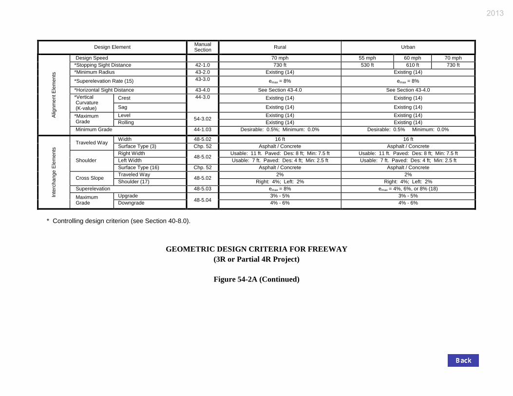
Figure 54-2A provides the Department’s criteria for the design of a 3R or partial 4R freeway project
for either a rural or an urban area. The designer should consider the following in the use of the table.
1. Design Manual Section References. The designer should review the appropriate section
references for greater insight into the design elements.
2. Footnotes. The table includes footnotes which are identified by a number in parentheses,
e.g., (6). The information in the footnotes is critical to the proper use of the table.
2013 Indiana Design Manual, Ch. 54 Page 11
3. Controlling Design Criteria. Controlling design criteria are identified with an asterisk. The
designer should evaluate the proposed design against the criteria shown in the table and
elsewhere in this chapter.
4. Design Exception. These standards are for use on an existing freeway including that on the
National Highway System. They are to be used for each project that is classified as 3R or
partial reconstruction regardless of funding source. Deviation from controlling design
criteria should be addressed in an approved design exception. Operational or maintenance
changes, permanent or temporary, exclusive of work-zone traffic control that create
substandard conditions such as by re-striping to obtain added lane(s) by reducing existing
lane widths or shoulders, must be addressed in a design exception whether or not actual
construction or reconstruction is involved.
54-3.0 GEOMETRIC DESIGN
Though Figure 54-2A provides the required geometric-design criteria, the designer must still make
certain decisions, such that some flexibility can be applied. These are discussed below.
The design criteria used for horizontal alignment excluding superelevation, vertical alignment, and
width of median or shoulders may be the AASHTO Interstate System criteria that were in effect at
the time of the route’s original construction or inclusion into the Interstate System.
54-3.01 Design Controls
54-3.01(01) Traffic-Volume Analysis
1. Design Life. The pavement-resurfacing portion of a 3R project should be designed using a
10-year design life. All other elements should have a design life of 20 years beyond the
expected construction date.
2. Level of Service (LOS). Figure 54-2A provides the desirable and minimum LOS criteria.
The geometric-design elements should be designed to be in accordance with the level-of-
service criteria for a design hourly volume at 20 years beyond the expected completion date.
3. Traffic Data. The designer should obtain the necessary traffic data from the Office of
Environmental Services. This should include current and future (10 and 20 years) AADT,
DHV, percent of trucks and buses (including that for each interchange), accident data for the
most recent 3-year period, and any known future traffic impact.
Page 12 2013 Indiana Design Manual, Ch. 54
4. Capacity Analysis. The analytical techniques in the Highway Capacity Manual and Chapter
41 will be used to conduct the capacity analysis.
54-3.01(02) Design Speed
Chapter 53 provides the Department’s criteria for selecting the design speed for a new construction
or complete 4R freeway project. These will also apply to a 3R/partial 4R freeway project. As a
minimum, the design speed for the original work may be used. Under restricted urban conditions,
the existing posted speed limit may be used as the design speed.
The design speed selected must equal or exceed the existing posted speed limit or a design exception
will be required. See Section 40-4.0 for additional information on design speed.
54-3.02 Horizontal and Vertical Alignment
Unless the specific objective of the freeway project is to improve one or more horizontal- or vertical-
alignment features, the existing alignment will be acceptable under the conditions as follows:
1. the design is in accordance with the AASHTO Interstate System criteria that were in effect at
the time of the route’s original construction or inclusion into the Interstate system; and
2. a review of the accident history for the past three years does not indicate a problem.
Once the decision has been made to reconstruct a horizontal- or vertical-alignment feature, the
designer should apply the criteria described in Chapter 43 or 44.
54-3.02(01) Superelevation
On a horizontal curve where the existing radius will be retained, it may be necessary to make
improvements to the superelevation. This may require revising the pavement-resurfacing thickness
to meet the superelevation criteria described in Sections 43-2.0 and 43-3.0. Where the pavement
structure will be reconstructed, the superelevation design should be in accordance with the new
construction criteria described in Sections 43-2.0 and 43-3.0.
2013 Indiana Design Manual, Ch. 54 Page 13
54-3.02(02) Grades
The maximum grades are shown in Figure 54-2A.
54-3.02(03) Vertical Clearance
The minimum vertical clearance is 16 ft over the entire roadway including the usable shoulder
widths for both the left and right shoulders. If practical, the 16-ft clearance should be provided at
each overpass within the project limits. If the 16-ft clearance cannot be obtained, a design exception
will be required. However, for the routes in Marion County listed below, an existing overpass with a
vertical clearance of at least 14 ft may be retained without a design exception.
1. I-65 from I-465 South to I-465 North;
2. I-70 from I-465 East to I-465 West; and
3. I-465 from I-69 Westward to I-65 North.
A low-clearance warning sign should be provided for each structure with a vertical clearance of less
than 14.5 ft.
54-3.03 Cross Section
54-3.03(01) Lane and Shoulder Width
Each travel-lane or shoulder width not in accordance with Figure 54-2A should be evaluated for
widening.
1. Travel Lane. The width of each travel lane or auxiliary lane should be 12 ft.
2. Shoulder. Existing shoulder widths may be retained if they are in accordance with the
AASHTO Interstate System criteria in effect at the time of the route’s original construction
or inclusion into the Interstate system.
54-3.03(02) Curbs
1. Safety Considerations. All existing curbs should be removed for safety reasons, unless they
are required for drainage.
Page 14 2013 Indiana Design Manual, Ch. 54
2. Type. If curbing is required for drainage, only sloping curbs will be permitted.
3. Guardrail. A curb in front of a guardrail may cause an errant vehicle to vault over or break
through the barrier. Where guardrail is used and curbing is necessary for drainage, the
maximum curb height should be 4 in. and should be placed behind the front face of the
guardrail.
54-3.03(03) Median
1. Width. The existing width should be retained.
2. Parallel Slopes. Existing slopes of 4:1 or flatter should be retained. If existing slopes are
flattened, the designer should consider the effect on drainage within the median.
3. Transverse Slopes. Transverse slopes for ditch checks or median crossovers should be 10:1
or flatter.
4. Median Opening. See Section 54-6.0 for information.
54-3.03(04) Fill or Cut Slope
1. No Roadway Widening. An existing slope of 2:1 or flatter should be retained. However, a
slope steeper than 4:1 should be evaluated for flattening.
2. Roadway Widening. If the lanes or shoulders are widened as part of the project, this will
produce a steeper fill slope or ditch foreslope (assuming the toe of fill slope or toe of
backslope remains in the same location). The roadside design should be modified to provide
a configuration which is the same as or flatter than the roadside cross section before the
project limits. As a minimum, the following will apply.
a. Embankment slope. A fill slope or ditch foreslope beginning at the shoulder break
should not be steeper than 4:1 unless steeper slopes can be justified in an engineering
and economic analysis. If the slope can be made flatter than 4:1, the designer should
desirably provide a 6:1 slope at least within the clear zone.
b. Ditch. If right of way is available, the existing ditch line should be moved outward
and the slopes flattened as much as practical. A drainage ditch within the clear zone
2013 Indiana Design Manual, Ch. 54 Page 15
should be regraded as much as practical to make it traversable for an errant vehicle.
See Section 49-3.02 for information on a traversable ditch.
c. Embankment Stability. Stable embankment material is required. Sod or other
appropriate materials or methods should be provided where erosion may be
considered a problem.
3. Roadside Safety. Upgrading the roadside safety is often an objective of the project. The
designer should consider the safety benefits of flattening fill or cut slopes to eliminate
guardrail and, as a minimum, to be in accordance with Item 2 above. An evaluation of run-
off-the-road accidents will assist in the assessment (see Chapter 50). See Section 54-4.0 for
more information on roadside-safety criteria.
54-3.03(05) Right of Way
Where practical, additional right of way should be secured to permit cost-effective geometric and
roadside-safety improvements.
54-3.03(06) Interchange
The project may include proposed work on an interchange. This work will only include selective
improvements to the interchange geometrics. This may include lengthening acceleration or
deceleration lanes, clearing the gore area, correcting the ramp superelevation, etc. The designer
should consider the following.
1. Desirable. The criteria provided in Chapter 48 should be used to design each interchange
element which will be improved as part of the freeway project.
2. Minimum. The criteria provided in the AASHTO A Policy on Geometric Design of
Highways and Streets may be used as the minimum design where INDOT’s criteria exceed
AASHTO’s. For example, Figures 54-3A and 54-3B may be used to determine deceleration
distance for a freeway exit instead of INDOT’s standard 1000-ft length.
3. Acceleration or Deceleration Lane. Only a parallel ramp exit or entrance should be used; see
Section 48-4.0. If converting a taper design to the preferred parallel design, the existing
taper portion that is less than 12 ft wide should be removed and reconstructed to provide the
full 12-ft width for the entire acceleration or deceleration length.
Page 16 2013 Indiana Design Manual, Ch. 54
4. Ramp Shoulder. Under restrictive conditions, an existing right-hand-side shoulder width of
7.5 ft may be retained.
54-4.0 ROADSIDE SAFETY
The project should be evaluated for potential roadside-safety improvements within the project limits.
The criteria described in Chapter 49 will apply to the evaluation. This includes roadside clear zone,
barrier warrants as shown in Figure 49-4G(1), barrier design, and drainage features.
Not all 2:1 fill slopes or foreslopes will require the use of guardrail. The designer first should
conduct a cost-effective analysis based on traffic volume, design speed, accident frequency, accident
cost, accident severity, installation costs, and repair costs to determine if guardrail is necessary.
Section 49-11.0 provides information on the AASHTO computer software program entitled
ROADSIDE, which should be used for the cost-effectiveness analysis.
54-5.0 BRIDGES
54-5.01 General
Figure 54-2A provides the Department’s criteria for structural capacity and width for a new or
reconstructed bridge, or for an existing bridge to remain in place. An existing bridge may remain in
place if it meets, or is upgraded to meet, the structural and geometric requirements described in
Figure 54-2A and Section 54-5.02. Upgrading a bridge to be in accordance with these criteria may
be considered if an engineering analysis determines that the upgrading is appropriate. Some of the
items that should be considered in the analysis include the following:
1. remaining service life;
2. sufficiency rating;
3. traffic volume;
4. clear-roadway width;
5. design speed; and
6. accident records.
If it is determined that a bridge should be replaced or undergo major reconstruction (e.g., replacing
superstructure, widening superstructure or substructure), the design will be in accordance with the
AASHTO LRFD criteria and load-carrying capacity (see Part VI).

2013 Indiana Design Manual, Ch. 54 Page 17
54-5.02 Bridge To Remain In Place
An existing bridge should be evaluated for possible upgrading or replacement (see Section 54-5.01),
if it is not in accordance with the following.
1. Width. The width should be evaluated against the criteria shown in Figure 54-2A.
2. Structural Capacity. The structural capacity should be evaluated against the criteria shown
in Figure 54-2A.
3. Vertical Clearance. An existing structure should provide at least a 16-ft vertical clearance
over the entire roadway including the usable shoulder widths for both left and right
shoulders. If it is necessary to retain a vertical clearance of less than 16 ft, a design-exception
request is required as described in Section 40-8.0. However, Section 54-3.02 provides a list
of routes foe which existing an overpass with a minimum 14-ft vertical clearance may be
retained without a design exception.
4. Bridge Railing. Only an existing bridge railing that have been proven to be acceptable
through crash testing may be retained. Each new bridge-railing installation should in
accordance with Section 61-6.01. Consideration should be given to widening the bridge at
the same time the railing is replaced to achieve the full approach-roadway width.
5. Approach-Barrier Transition. An approaching barrier transition should be in accordance
with Chapter 49 and the INDOT Standard Drawings.
54-6.0 MEDIAN OPENING
On a fully access-controlled freeway, median crossing is denied to the public. However, an
occasional median opening or emergency crossover is required to accommodate maintenance,
snowplowing, or emergency service vehicles.
54-6.01 Guidelines
A median crossover should be placed away from a mainline conflict, such as an interchange. The
number and location of median crossovers should be kept to a minimum.
1. Spacing. A median opening may be provided if it is in accordance with the spacing
requirements as follows:
Page 18 2013 Indiana Design Manual, Ch. 54
a. A median crossover may be provided approximately half way between two
interchanges if the spacing between them is greater than 3 mi but less than 4 mi.
b. Multiple crossovers may be provided such that the distance between each crossover
or interchange is not greater than 3 mi if the spacing between interchanges is greater
than 4 mi.
2. Jurisdiction. A median crossover may be appropriate at a State line or a division line
between districts or subdistricts.
3. Urban. A crossover should not be located in an urban area or an area with a narrow median.
4. Interstate-Route Usage. Section 54-6.04 provides a listing of the FHWA-approved crossover
sites on the Interstate System.
5. Rest Area or Weigh Station. A crossover should be located at least 1500 ft from the end of
the exit or entrance ramp taper for a rest area or weigh station.
54-6.02 Implementation
If warranted as discussed in Section 54-6.01, each new crossover on an existing facility should be in
accordance with 54-6.03. The addition of a median crossover, either during construction or after the
highway is in use, requires the approval of the Chief Engineer and concurrence from the FHWA.
54-6.03 Design
The INDOT Standard Drawings provide the criteria for the design of a freeway crossover. The
designer should also consider the following.
1. Interchange or Lane Drop. A crossover should be at least 1500 ft from the terminus of an
exit ramp, entrance ramp, or lane drop.
2. Overhead Structure. A crossover should be located at least 1500 ft from a structure crossing
over the freeway.
3. Sight Distance. Because of unexpected nature of a U-turn maneuver, adequate sight distance
should be available at a crossover. Decision sight distance should be provided in both
2013 Indiana Design Manual, Ch. 54 Page 19
directions. This would favor, for example, placing the crossover in a sag vertical curve. The
minimum stopping sight distance should be provided.
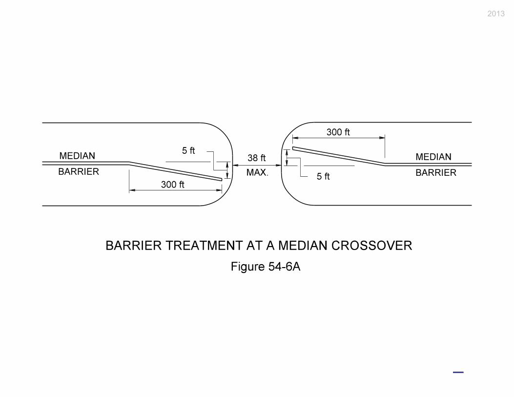
4. Median Barrier. A crossover should be avoided where a median barrier is present. If a
crossover must be provided, the barrier should be flared as shown in Figure 54-6A, or
terminated with an appropriate end treatment as discussed in Chapter 49. The width of the
opening should not be greater than 35 ft.
6. Horizontal Curve. A crossover should not be located within a curve requiring
superelevation.
7. Pavement. The crossover pavement will be constructed with an asphalt surface of sufficient
strength to accommodate the largest expected vehicle (e.g., fully loaded dump truck, fire
truck). See Chapter 52.
8. Drainage. A crossover should be located such that an additional drainage structure would
not be required. The designer should review the median drainage patterns to ensure that the
median crossover will not negatively disrupt the median drainage (e.g., cause ponding in the
median). If a culvert is required under the crossover, consideration should be given to
providing inlets or culvert end sections which are in accordance with Section 49-3.03 and the
INDOT Standard Drawings.
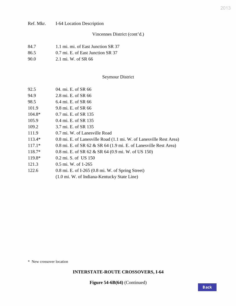
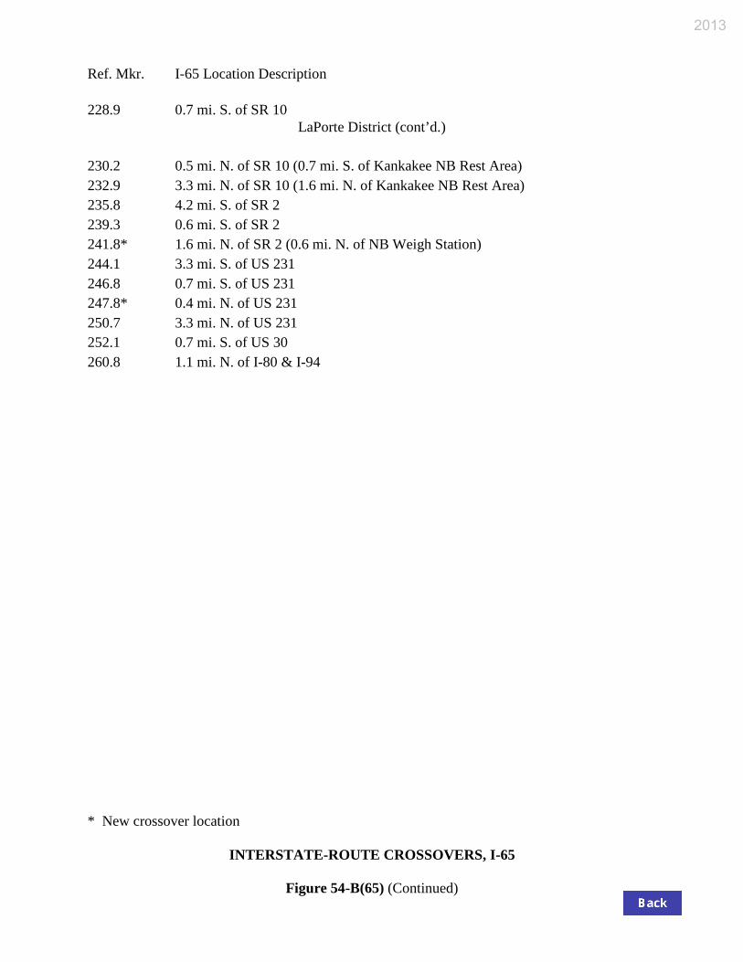
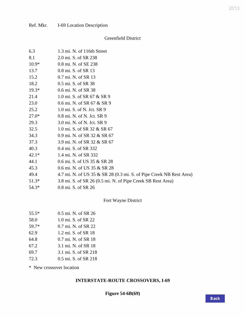
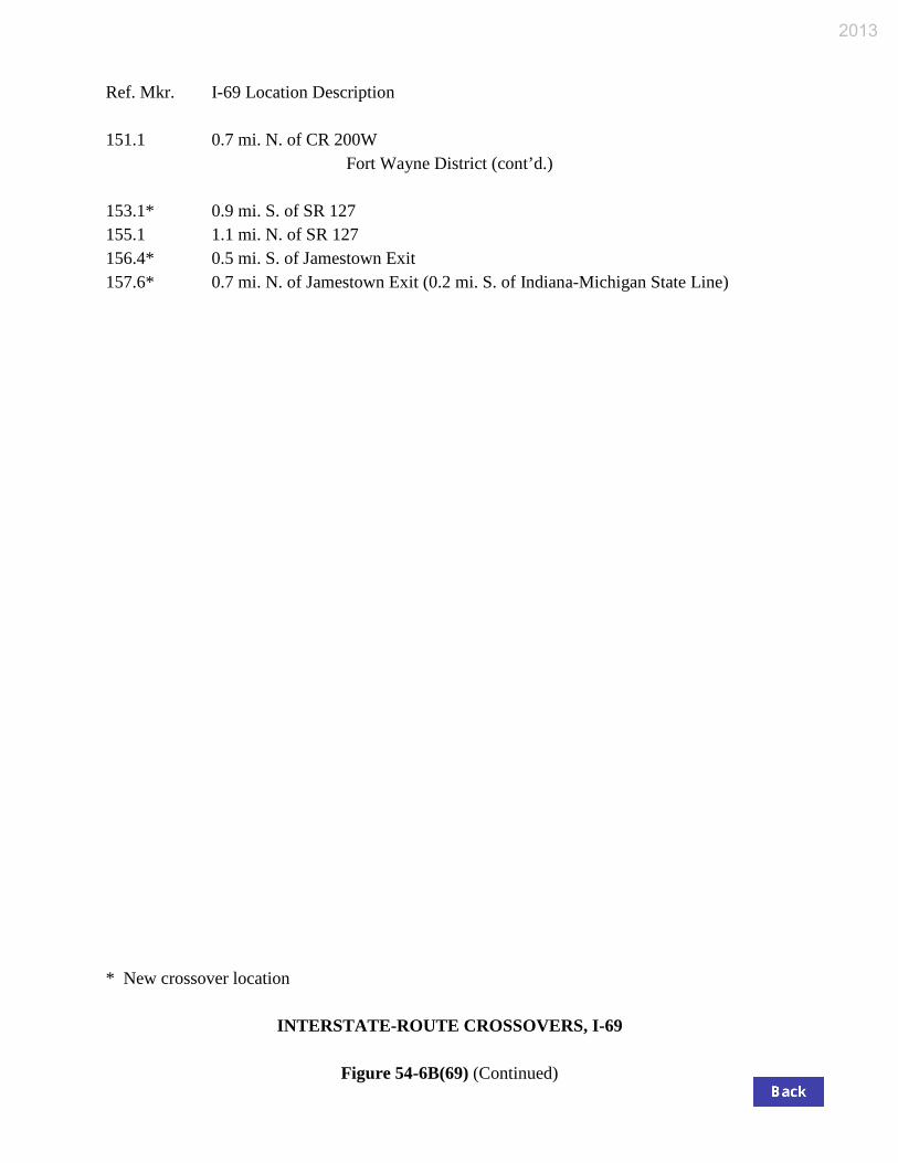
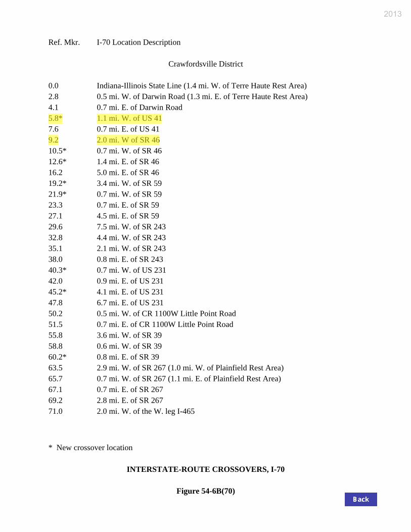
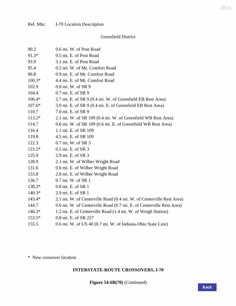
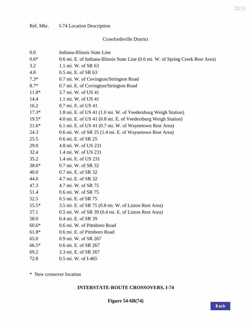
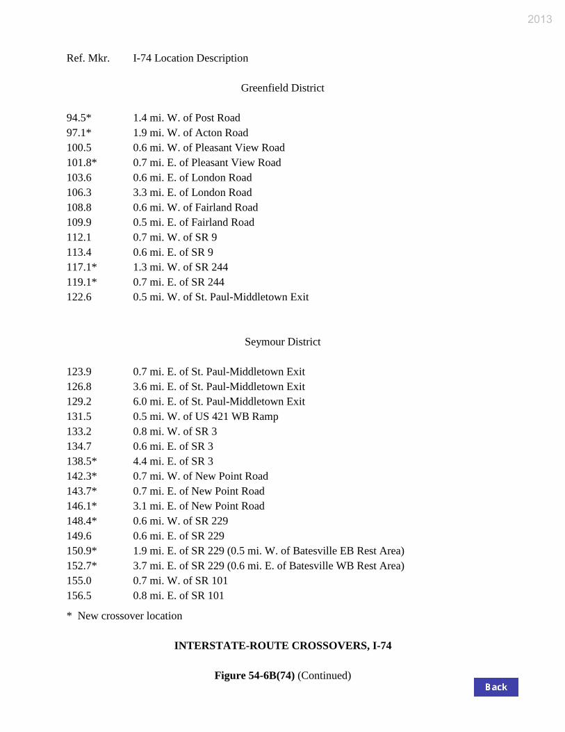
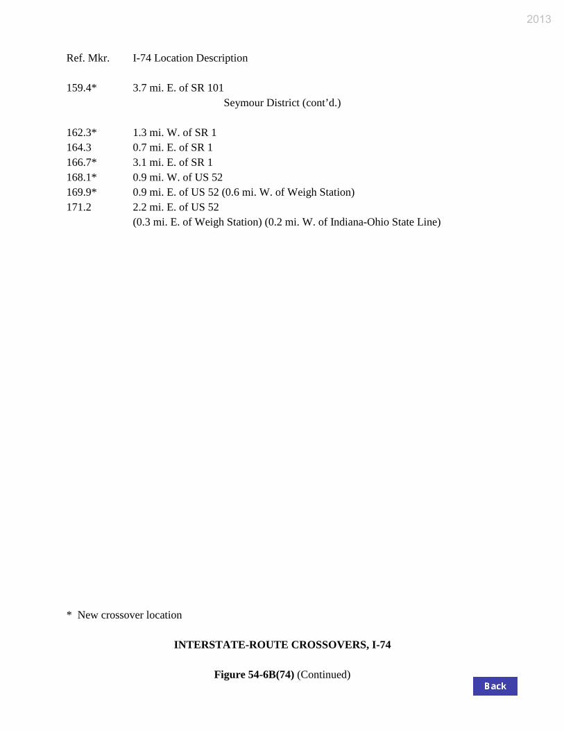
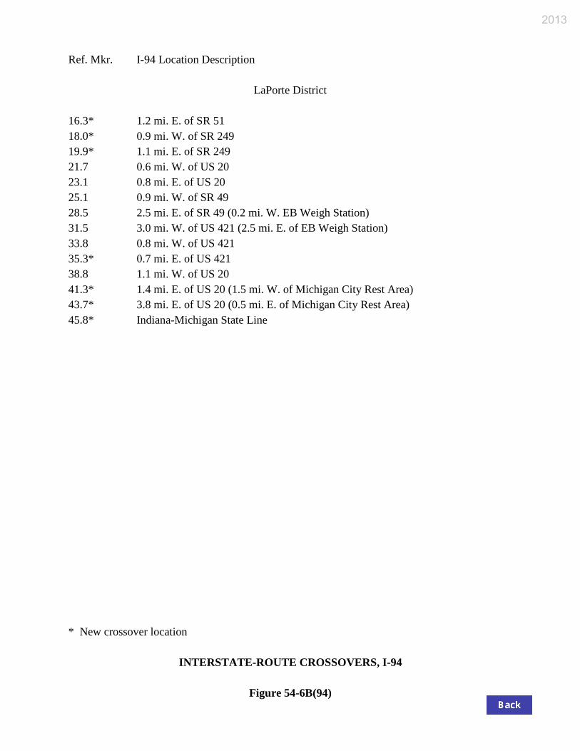
54-6.04 Location of Interstate-Route Crossover
The FHWA-approved sites for median crossovers on the Interstate system are listed in Figure 54-
6B(64) for I-64, Figure 54-6B(65) for I-65, Figure 54-6B(69) for I-69, Figure 54-6B(70) for I-70,
Figure 54-6B(74) for I-74, Figure 54-6B(94) for I-94, or Figure 54-6B(100) for the three-digit-
numbered routes. The sites are listed according to district, reference marker, and location
description.

Design Element Manual Section Rural Urban
Des
ign
Con
trols
Design Forecast Year 54-3.01 20 Years (1) 20 Years (1) *Design Speed (mph) 54-3.01 Min: Original Design Speed Min: Original Design Speed (2) Access Control 40-5.0 Full Control Full Control Level of Service 40-2.04 Desirable: B; Minimum: C Desirable: B; Minimum: D
Cro
ss S
ectio
n E
lem
ents
Travel Lane *Width 54-3.03 12 ft 12 ft Surface Type(3) Chp. 52 Asphalt / Concrete Asphalt / Concrete
Shoulder *Right Width(4)
54-3.03 Usable: 11 ft; Paved: 10 ft Usable: 11 ft; Paved: 10 ft
*Left Width(5) 2 Lanes: 4 ft Paved. 3 Lanes: 10 ft Paved 2 Lanes: 4 ft Paved. 3 Lanes: 10 ft Paved Surface Type(3) Chp. 52 Asphalt / Concrete Asphalt / Concrete
Cross Slope *Travel Lane (6) 45-1.01 2% 2%
Shoulder (6A) 45-1.02 Paved Width ≤ 4 ft: 2%; Paved Width > 4 ft: 4%
Paved Width ≤ 4 ft: 2%; Paved Width > 4 ft: 4%
Auxiliary Lane *Lane Width
45-1.03 12 ft 12 ft
*Shoulder Width Left or Right: Des: 12 ft; Min: 6 ft Left or Right: Des: 12 ft; Min: 6 ft
Median Width Depressed
54-3.03 Existing Existing
Flush (CMB) Existing Existing Clear Zone 49-2.0 (8) (8)
Side Slopes (9) Cut
Foreslope 54-3.03
2:1 or Flatter 2:1 or Flatter Ditch Width Existing Existing Backslope 2:1 or Flatter 2:1 or Flatter
Fill 45-3.0 2:1 or Flatter 2:1 or Flatter
Median Slopes 45-3.03 Desirable: 8:1; Maximum: 4:1 Desirable: 8:1; Maximum: 4:1
Brid
ges
New or Reconstructed Bridge
*Structural Capacity Chp. 60 HL-93 (10) HL-93 (10)
*Clear-Roadway Width(11) 54-5.0 Full Paved Approach Width Full Paved Approach Width
Existing Bridge to Remain in Place
*Structural Capacity Chp. 72 HS-20 HS-20
*Clear-Roadway Width 54-5.0 Travelway Plus 10 ft Rt. & 4 ft Lt. Shoulders (7)
Travelway Plus 10 ft Rt. & 4 ft Lt. Shoulders (7)
*Vertical Clearance (Freeway Under) (12a)
New or Replaced Overpassing Bridge (12b)
54-5.0
16.5 ft 16.5 ft (12c)
Existing Overpassing Bridge 16 ft 16 ft (12c)
Sign Truss / Pedestrian Bridge New: 17.5 ft; Existing: 17 ft New: 17.5 ft; Existing: 17 ft
Vertical Clearance (Freeway over Railroad) (13)
Chp. 69 23 ft 23 ft
* Controlling design criterion (see Section 40-8.0).
GEOMETRIC DESIGN CRITERIA FOR FREEWAY (3R or Partial 4R Project)
Figure 54-2A
2013
Design Element Manual Section Rural Urban
Alig
nmen
t Ele
men
ts
Design Speed 70 mph 55 mph 60 mph 70 mph *Stopping Sight Distance 42-1.0 730 ft 530 ft 610 ft 730 ft *Minimum Radius 43-2.0 Existing (14) Existing (14)
*Superelevation Rate (15) 43-3.0 emax = 8% emax = 8%
*Horizontal Sight Distance 43-4.0 See Section 43-4.0 See Section 43-4.0 *Vertical Curvature (K-value)
Crest 44-3.0 Existing (14) Existing (14)
Sag Existing (14) Existing (14)
*Maximum Grade
Level 54-3.02
Existing (14) Existing (14) Rolling Existing (14) Existing (14)
Minimum Grade 44-1.03 Desirable: 0.5%; Minimum: 0.0% Desirable: 0.5% Minimum: 0.0%
Inte
rcha
nge
Ele
men
ts Traveled Way
Width 48-5.02 16 ft 16 ft Surface Type (3) Chp. 52 Asphalt / Concrete Asphalt / Concrete
Shoulder Right Width
48-5.02 Usable: 11 ft. Paved: Des: 8 ft; Min: 7.5 ft Usable: 11 ft. Paved: Des: 8 ft; Min: 7.5 ft
Left Width Usable: 7 ft. Paved: Des: 4 ft; Min: 2.5 ft Usable: 7 ft. Paved: Des: 4 ft; Min: 2.5 ft Surface Type (16) Chp. 52 Asphalt / Concrete Asphalt / Concrete
Cross Slope Traveled Way
48-5.02 2% 2%
Shoulder (17) Right: 4%; Left: 2% Right: 4%; Left: 2% Superelevation 48-5.03 emax = 8% emax = 4%, 6%, or 8% (18)
Maximum Grade
Upgrade 48-5.04
3% - 5% 3% - 5% Downgrade 4% - 6% 4% - 6%
* Controlling design criterion (see Section 40-8.0).
GEOMETRIC DESIGN CRITERIA FOR FREEWAY
(3R or Partial 4R Project)
Figure 54-2A (Continued)
2013
GEOMETRIC DESIGN CRITERIA FOR FREEWAY (3R or Partial 4R Project)
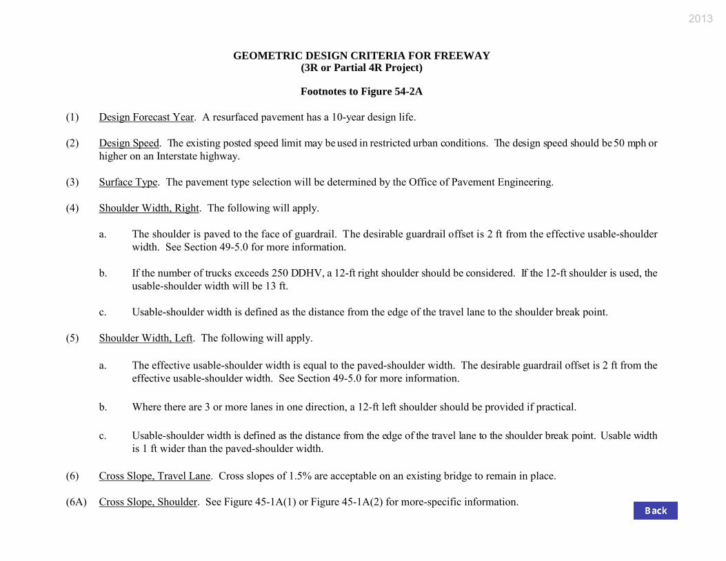
Footnotes to Figure 54-2A
(1) Design Forecast Year. A resurfaced pavement has a 10-year design life. (2) Design Speed. The existing posted speed limit may be used in restricted urban conditions. The design speed should be 50 mph or
higher on an Interstate highway. (3) Surface Type. The pavement type selection will be determined by the Office of Pavement Engineering. (4) Shoulder Width, Right. The following will apply. a. The shoulder is paved to the face of guardrail. The desirable guardrail offset is 2 ft from the effective usable-shoulder
width. See Section 49-5.0 for more information. b. If the number of trucks exceeds 250 DDHV, a 12-ft right shoulder should be considered. If the 12-ft shoulder is used, the
usable-shoulder width will be 13 ft. c. Usable-shoulder width is defined as the distance from the edge of the travel lane to the shoulder break point. (5) Shoulder Width, Left. The following will apply.
a. The effective usable-shoulder width is equal to the paved-shoulder width. The desirable guardrail offset is 2 ft from the effective usable-shoulder width. See Section 49-5.0 for more information.
b. Where there are 3 or more lanes in one direction, a 12-ft left shoulder should be provided if practical.
c. Usable-shoulder width is defined as the distance from the edge of the travel lane to the shoulder break point. Usable width
is 1 ft wider than the paved-shoulder width. (6) Cross Slope, Travel Lane. Cross slopes of 1.5% are acceptable on an existing bridge to remain in place. (6A) Cross Slope, Shoulder. See Figure 45-1A(1) or Figure 45-1A(2) for more-specific information.
2013
GEOMETRIC DESIGN CRITERIA FOR FREEWAY (3R or Partial 4R Project)
Footnotes to Figure 54-2A (Continued)
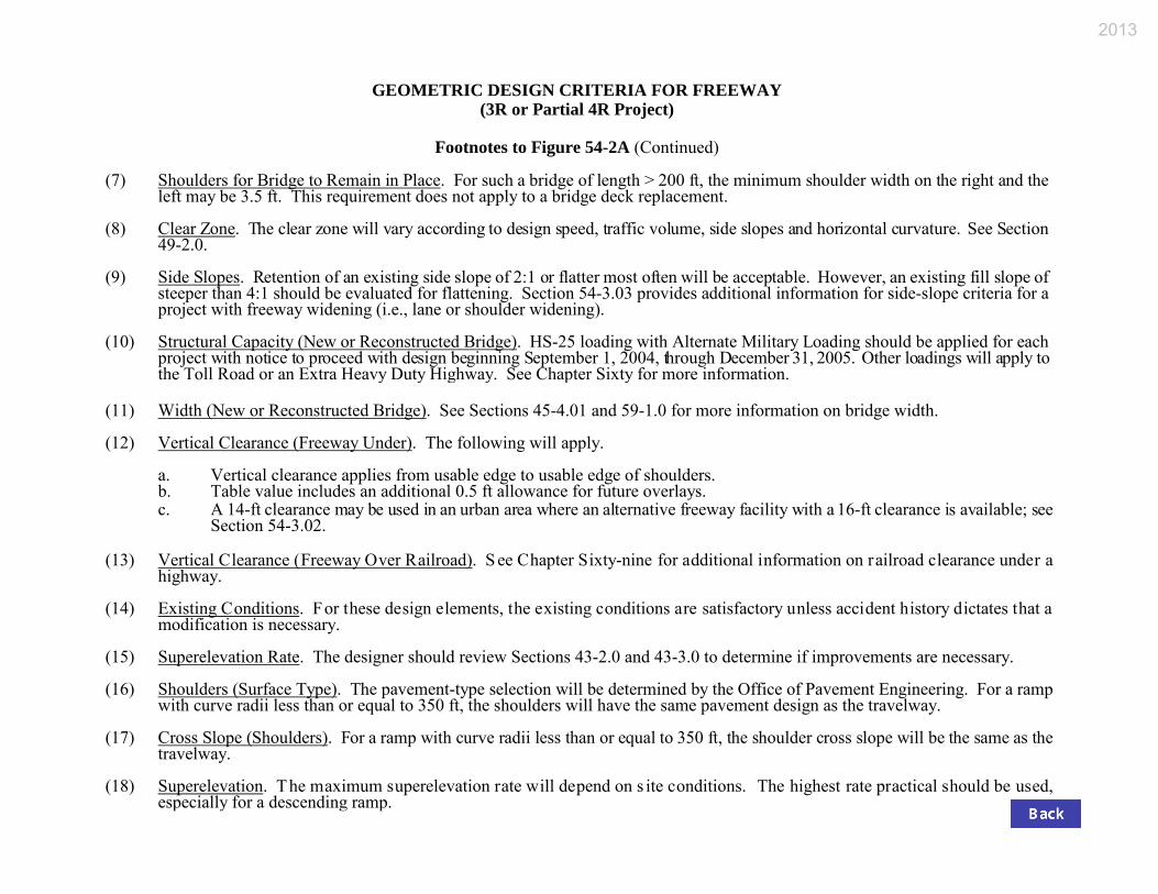
(7) Shoulders for Bridge to Remain in Place. For such a bridge of length > 200 ft, the minimum shoulder width on the right and the
left may be 3.5 ft. This requirement does not apply to a bridge deck replacement. (8) Clear Zone. The clear zone will vary according to design speed, traffic volume, side slopes and horizontal curvature. See Section
49-2.0. (9) Side Slopes. Retention of an existing side slope of 2:1 or flatter most often will be acceptable. However, an existing fill slope of
steeper than 4:1 should be evaluated for flattening. Section 54-3.03 provides additional information for side-slope criteria for a project with freeway widening (i.e., lane or shoulder widening).
(10) Structural Capacity (New or Reconstructed Bridge). HS-25 loading with Alternate Military Loading should be applied for each
project with notice to proceed with design beginning September 1, 2004, through December 31, 2005. Other loadings will apply to the Toll Road or an Extra Heavy Duty Highway. See Chapter Sixty for more information.
(11) Width (New or Reconstructed Bridge). See Sections 45-4.01 and 59-1.0 for more information on bridge width. (12) Vertical Clearance (Freeway Under). The following will apply.
a. Vertical clearance applies from usable edge to usable edge of shoulders. b. Table value includes an additional 0.5 ft allowance for future overlays. c. A 14-ft clearance may be used in an urban area where an alternative freeway facility with a 16-ft clearance is available; see
Section 54-3.02. (13) Vertical Clearance (Freeway Over Railroad). S ee Chapter Sixty-nine for additional information on railroad clearance under a
highway. (14) Existing Conditions. For these design elements, the existing conditions are satisfactory unless accident history dictates that a
modification is necessary. (15) Superelevation Rate. The designer should review Sections 43-2.0 and 43-3.0 to determine if improvements are necessary. (16) Shoulders (Surface Type). The pavement-type selection will be determined by the Office of Pavement Engineering. For a ramp
with curve radii less than or equal to 350 ft, the shoulders will have the same pavement design as the travelway. (17) Cross Slope (Shoulders). For a ramp with curve radii less than or equal to 350 ft, the shoulder cross slope will be the same as the
travelway. (18) Superelevation. The maximum superelevation rate will depend on s ite conditions. The highest rate practical should be used,
especially for a descending ramp.
2013
Highway Design Speed (mph)
Average Running Speed,
Va (mph)
L = Deceleration Length (ft) For Design Speed of First Governing Geometric Control (mph)
Stop 15 20 25 30 40 45 50 For Average Running Speed, V′a (mph)
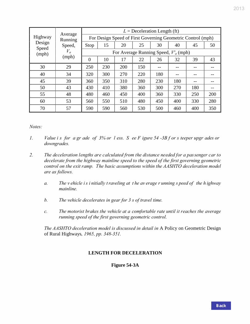
0 10 17 22 26 32 39 43 30 29 250 230 200 150 -- -- -- -- 40 34 320 300 270 220 180 -- -- -- 45 39 360 350 310 280 230 180 -- -- 50 43 430 410 380 360 300 270 180 -- 55 48 480 460 450 400 360 330 250 200 60 53 560 550 510 480 450 400 330 280 70 57 590 590 560 530 500 460 400 350
Notes: 1. Value i s for a gr ade of 3% or l ess. S ee F igure 54 -3B f or s teeper upgr ades or
downgrades. 2. The deceleration lengths are calculated from the distance needed for a passenger car to
decelerate from the highway mainline speed to the speed of the first governing geometric control on the exit ramp. The basic assumptions within the AASHTO deceleration model are as follows.
a. The v ehicle i s i nitially t raveling at t he av erage r unning s peed of the h ighway
mainline.
b. The vehicle decelerates in gear for 3 s of travel time.
c. The motorist brakes the vehicle at a comfortable rate until it reaches the average running speed of the first governing geometric control.
The AASHTO deceleration model is discussed in detail in A Policy on Geometric Design
of Rural Highways, 1965, pp. 348-351.
LENGTH FOR DECELERATION
Figure 54-3A
2013
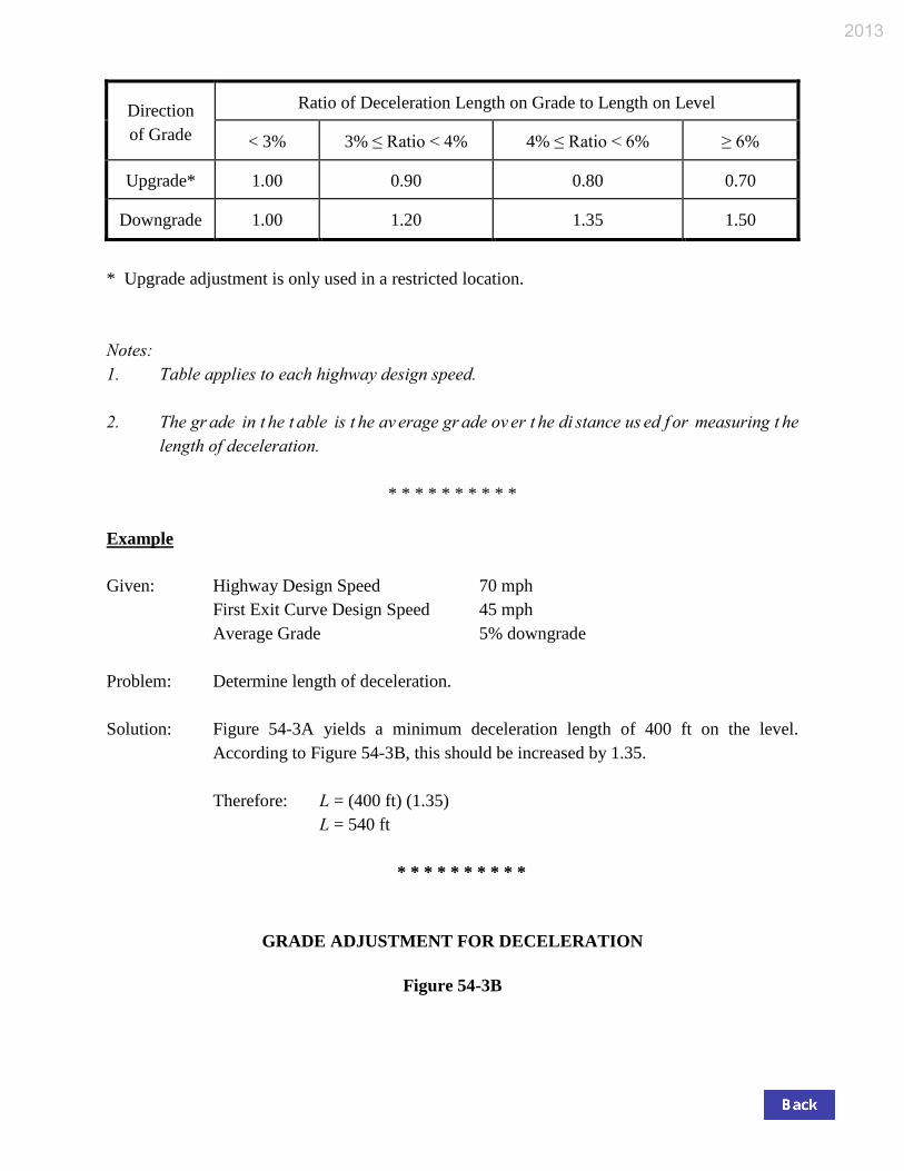
Direction of Grade
Ratio of Deceleration Length on Grade to Length on Level
< 3% 3% ≤ Ratio < 4% 4% ≤ Ratio < 6% ≥ 6%
Upgrade* 1.00 0.90 0.80 0.70
Downgrade 1.00 1.20 1.35 1.50
* Upgrade adjustment is only used in a restricted location. Notes: 1. Table applies to each highway design speed. 2. The gr ade in t he t able is t he av erage gr ade ov er t he di stance us ed f or measuring t he
length of deceleration.
* * * * * * * * * * Example Given: Highway Design Speed 70 mph
First Exit Curve Design Speed 45 mph Average Grade 5% downgrade
Problem: Determine length of deceleration. Solution: Figure 54-3A yields a minimum deceleration length of 400 ft on the level.
According to Figure 54-3B, this should be increased by 1.35.
Therefore: L = (400 ft) (1.35) L = 540 ft
* * * * * * * * * *
GRADE ADJUSTMENT FOR DECELERATION
Figure 54-3B
2013
2013

Ref. Mkr. I-64 Location Description
* New crossover location INTERSTATE-ROUTE CROSSOVERS, I-64 Figure 54-6B(64)
Vincennes District 0.8 0.8 mi. E. of Indiana-Illinois State Line 3.7 0.7 mi. W. of Griffin Road 5.1 0.7 mi. E. of Griffin Road 6.9* 2.5 mi. E. of Griffin Road (0.4 mi. W. of Black River Rest Area) 8.9 4.5 mi. E. of Griffin Road (1.2 mi. E. of Black River Rest Area) 10.9 1.0 mi. W. of SR 165 12.4* 0.5 mi. E. of SR 165 16.9 0.8 mi. W. of SR 65 18.2 0.5 mi. E. of SR 65 19.8 2.1 mi. E. of SR 65 23.3 1.7 mi. W. of US 41 25.8* 0.8 mi. E. of US 41 28.8 0.6 mi. W. of SR 57 & I-164 30.2* 0.8 mi. E. of SR 57 & I-164 33.3 3.9 mi. E. of SR 57 & I-164 36.8 2.5 mi. W. of SR 61 38.7 0.6 mi. W. of SR 61 40.2 0.9 mi. E. of SR 61 43.6 4.3 mi. E. of SR 61 46.9* 7.6 mi. E. of SR 61 50.2 3.4 mi. W. of SR 161 53.1* 0.5 mi. W. of SR 161 54.3* 0.6 mi. E. of SR 161 55.9 0.9 mi. W. of US 231 57.7 1.0 mi. E. of US 231 (0.3 mi. W. of Dale Rest Area) 59.9 3.1 mi. W. of SR 162 (1.4 mi. E. of Dale Rest Area) 62.3 0.7 mi. W. of SR 162 63.7 0.7 mi. E. of SR 162 68.6* 5.6 mi. W. of SR 162 71.7 0.7 mi. W. of SR 145 73.0* 0.6 mi. E. of SR 145 75.5* 3.1 mi. E. of SR 145 78.0 0.6 mi. W. of West Junction SR 37 79.2 1.8 mi. W. of West Junction SR 37
2013
Ref. Mkr. I-64 Location Description
* New crossover location INTERSTATE-ROUTE CROSSOVERS, I-64 Figure 54-6B(64) (Continued)
Vincennes District (cont’d.) 84.7 1.1 mi. mi. of East Junction SR 37 86.5 0.7 mi. E. of East Junction SR 37 90.0 2.1 mi. W. of SR 66
Seymour District 92.5 04. mi. E. of SR 66 94.9 2.8 mi. E. of SR 66 98.5 6.4 mi. E. of SR 66 101.9 9.8 mi. E. of SR 66 104.8* 0.7 mi. E. of SR 135 105.9 0.4 mi. E. of SR 135 109.2 3.7 mi. E. of SR 135 111.9 0.7 mi. W. of Lanesville Road 113.4* 0.8 mi. E. of Lanesville Road (1.1 mi. W. of Lanesville Rest Area) 117.1* 0.8 mi. E. of SR 62 & SR 64 (1.9 mi. E. of Lanesville Rest Area) 118.7* 0.8 mi. E. of SR 62 & SR 64 (0.9 mi. W. of US 150) 119.8* 0.2 mi. S. of US 150 121.3 0.5 mi. W. of 1-265 122.6 0.8 mi. E. of I-265 (0.8 mi. W. of Spring Street) (1.0 mi. W. of Indiana-Kentucky State Line)
2013
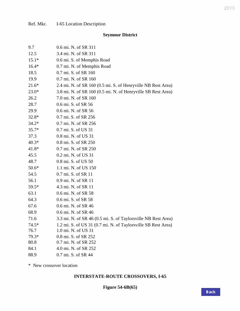
Ref. Mkr. I-65 Location Description
* New crossover location INTERSTATE-ROUTE CROSSOVERS, I-65 Figure 54-6B(65)
Seymour District 9.7 0.6 mi. N. of SR 311 12.5 3.4 mi. N. of SR 311 15.1* 0.6 mi. S. of Memphis Road 16.4* 0.7 mi. N. of Memphis Road 18.5 0.7 mi. S. of SR 160 19.9 0.7 mi. N. of SR 160 21.6* 2.4 mi. N. of SR 160 (0.5 mi. S. of Henryville NB Rest Area) 23.0* 3.8 mi. N. of SR 160 (0.5 mi. N. of Henryville SB Rest Area) 26.2 7.0 mi. N. of SR 160 28.7 0.6 mi. S. of SR 56 29.9 0.6 mi. N. of SR 56 32.8* 0.7 mi. S. of SR 256 34.2* 0.7 mi. N. of SR 256 35.7* 0.7 mi. S. of US 31 37.3 0.8 mi. N. of US 31 40.3* 0.8 mi. S. of SR 250 41.8* 0.7 mi. N. of SR 250 45.5 0.2 mi. N. of US 31 48.7 0.8 mi. S. of US 50 50.6* 1.1 mi. N. of US 150 54.5 0.7 mi. S. of SR 11 56.1 0.9 mi. N. of SR 11 59.5* 4.3 mi. N. of SR 11 63.1 0.6 mi. N. of SR 58 64.3 0.6 mi. S. of SR 58 67.6 0.6 mi. N. of SR 46 68.9 0.6 mi. N. of SR 46 71.6 3.3 mi. N. of SR 46 (0.5 mi. S. of Taylorsville NB Rest Area) 74.5* 1.2 mi. S. of US 31 (0.7 mi. N. of Taylorsville SB Rest Area) 76.7 1.0 mi. N. of US 31 79.3* 0.8 mi. S. of SR 252 80.8 0.7 mi. N. of SR 252 84.1 4.0 mi. N. of SR 252 88.9 0.7 mi. S. of SR 44
2013
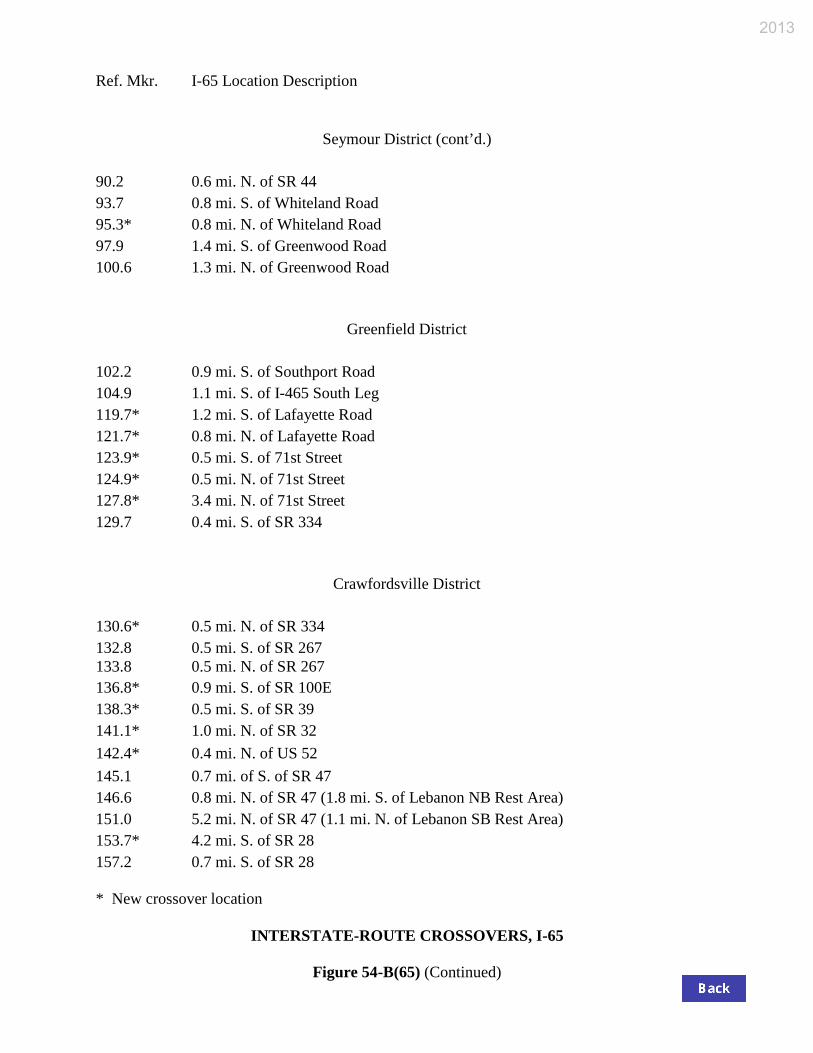
Ref. Mkr. I-65 Location Description
* New crossover location INTERSTATE-ROUTE CROSSOVERS, I-65 Figure 54-B(65) (Continued)
Seymour District (cont’d.)
90.2 0.6 mi. N. of SR 44 93.7 0.8 mi. S. of Whiteland Road 95.3* 0.8 mi. N. of Whiteland Road 97.9 1.4 mi. S. of Greenwood Road 100.6 1.3 mi. N. of Greenwood Road
Greenfield District 102.2 0.9 mi. S. of Southport Road 104.9 1.1 mi. S. of I-465 South Leg 119.7* 1.2 mi. S. of Lafayette Road 121.7* 0.8 mi. N. of Lafayette Road 123.9* 0.5 mi. S. of 71st Street 124.9* 0.5 mi. N. of 71st Street 127.8* 3.4 mi. N. of 71st Street 129.7 0.4 mi. S. of SR 334
Crawfordsville District 130.6* 0.5 mi. N. of SR 334 132.8 0.5 mi. S. of SR 267 133.8 0.5 mi. N. of SR 267 136.8* 0.9 mi. S. of SR 100E 138.3* 0.5 mi. S. of SR 39 141.1* 1.0 mi. N. of SR 32 142.4* 0.4 mi. N. of US 52 145.1 0.7 mi. of S. of SR 47 146.6 0.8 mi. N. of SR 47 (1.8 mi. S. of Lebanon NB Rest Area) 151.0 5.2 mi. N. of SR 47 (1.1 mi. N. of Lebanon SB Rest Area) 153.7* 4.2 mi. S. of SR 28 157.2 0.7 mi. S. of SR 28
2013
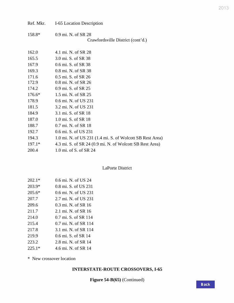
Ref. Mkr. I-65 Location Description
* New crossover location INTERSTATE-ROUTE CROSSOVERS, I-65 Figure 54-B(65) (Continued)
158.8* 0.9 mi. N. of SR 28 Crawfordsville District (cont’d.)
162.0 4.1 mi. N. of SR 28 165.5 3.0 mi. S. of SR 38 167.9 0.6 mi. S. of SR 38 169.3 0.8 mi. N. of SR 38 171.6 0.5 mi. S. of SR 26 172.9 0.8 mi. N. of SR 26 174.2 0.9 mi. S. of SR 25 176.6* 1.5 mi. N. of SR 25 178.9 0.6 mi. N. of US 231 181.5 3.2 mi. N. of US 231 184.9 3.1 mi. S. of SR 18 187.0 1.0 mi. S. of SR 18 188.7 0.7 mi. N. of SR 18 192.7 0.6 mi. S. of US 231 194.3 1.0 mi. N. of US 231 (1.4 mi. S. of Wolcott SB Rest Area) 197.1* 4.3 mi. S. of SR 24 (0.9 mi. N. of Wolcott SB Rest Area) 200.4 1.0 mi. of S. of SR 24
LaPorte District 202.1* 0.6 mi. N. of US 24 203.9* 0.8 mi. S. of US 231 205.6* 0.6 mi. N. of US 231 207.7 2.7 mi. N. of US 231 209.6 0.3 mi. N. of SR 16 211.7 2.1 mi. N. of SR 16 214.0 0.7 mi. S. of SR 114 215.4 0.7 mi. N. of SR 114 217.8 3.1 mi. N. of SR 114 219.9 0.6 mi. S. of SR 14 223.2 2.8 mi. N. of SR 14 225.1* 4.6 mi. N. of SR 14
2013
Ref. Mkr. I-65 Location Description
* New crossover location INTERSTATE-ROUTE CROSSOVERS, I-65 Figure 54-B(65) (Continued)
228.9 0.7 mi. S. of SR 10 LaPorte District (cont’d.)
230.2 0.5 mi. N. of SR 10 (0.7 mi. S. of Kankakee NB Rest Area) 232.9 3.3 mi. N. of SR 10 (1.6 mi. N. of Kankakee NB Rest Area) 235.8 4.2 mi. S. of SR 2 239.3 0.6 mi. S. of SR 2 241.8* 1.6 mi. N. of SR 2 (0.6 mi. N. of NB Weigh Station) 244.1 3.3 mi. S. of US 231 246.8 0.7 mi. S. of US 231 247.8* 0.4 mi. N. of US 231 250.7 3.3 mi. N. of US 231 252.1 0.7 mi. S. of US 30 260.8 1.1 mi. N. of I-80 & I-94
2013
Ref. Mkr. I-69 Location Description
* New crossover location INTERSTATE-ROUTE CROSSOVERS, I-69 Figure 54-6B(69)
Greenfield District 6.3 1.3 mi. N. of 116th Street 8.1 2.0 mi. S. of SR 238 10.9* 0.8 mi. N. of SE 238 13.7 0.8 mi. S. of SR 13 15.2 0.7 mi. N. of SR 13 18.2 0.5 mi. S. of SR 38 19.3* 0.6 mi. N. of SR 38 21.4 1.0 mi. S. of SR 67 & SR 9 23.0 0.6 mi. N. of SR 67 & SR 9 25.2 1.0 mi. S. of N. Jct. SR 9 27.0* 0.8 mi. N. of N. Jct. SR 9 29.3 3.0 mi. N. of N. Jct. SR 9 32.5 1.0 mi. S. of SR 32 & SR 67 34.3 0.9 mi. N. of SR 32 & SR 67 37.3 3.9 mi. N. of SR 32 & SR 67 40.3 0.4 mi. S. of SR 332 42.1* 1.4 mi. N. of SR 332 44.1 0.6 mi. S. of US 35 & SR 28 45.3 0.6 mi. N. of US 35 & SR 28 49.4 4.7 mi. N. of US 35 & SR 28 (0.3 mi. S. of Pipe Creek NB Rest Area) 51.3* 3.8 mi. S. of SR 26 (0.5 mi. N. of Pipe Creek SB Rest Area) 54.3* 0.8 mi. S. of SR 26
Fort Wayne District 55.5* 0.5 mi. N. of SR 26 58.0 1.0 mi. S. of SR 22 59.7* 0.7 mi. N. of SR 22 62.9 1.2 mi. S. of SR 18 64.8 0.7 mi. N. of SR 18 67.2 3.1 mi. N. of SR 18 69.7 3.1 mi. S. of SR 218 72.3 0.5 mi. S. of SR 218
2013
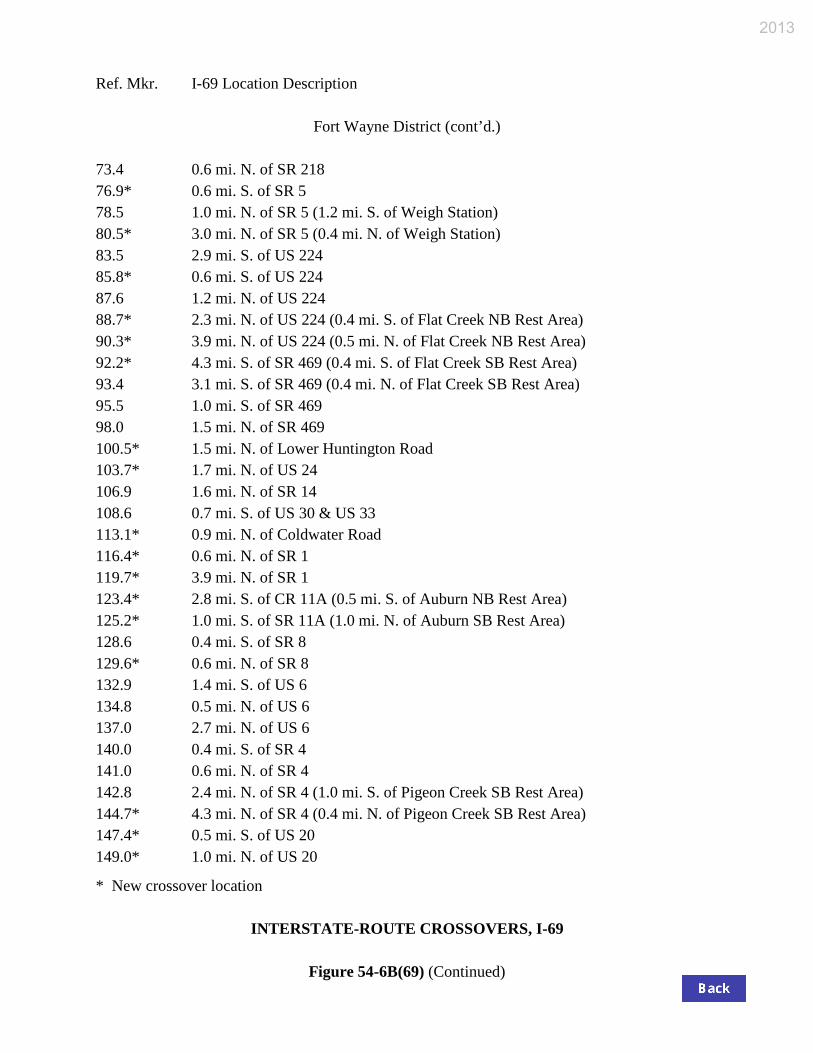
Ref. Mkr. I-69 Location Description
* New crossover location INTERSTATE-ROUTE CROSSOVERS, I-69 Figure 54-6B(69) (Continued)
Fort Wayne District (cont’d.) 73.4 0.6 mi. N. of SR 218 76.9* 0.6 mi. S. of SR 5 78.5 1.0 mi. N. of SR 5 (1.2 mi. S. of Weigh Station) 80.5* 3.0 mi. N. of SR 5 (0.4 mi. N. of Weigh Station) 83.5 2.9 mi. S. of US 224 85.8* 0.6 mi. S. of US 224 87.6 1.2 mi. N. of US 224 88.7* 2.3 mi. N. of US 224 (0.4 mi. S. of Flat Creek NB Rest Area) 90.3* 3.9 mi. N. of US 224 (0.5 mi. N. of Flat Creek NB Rest Area) 92.2* 4.3 mi. S. of SR 469 (0.4 mi. S. of Flat Creek SB Rest Area) 93.4 3.1 mi. S. of SR 469 (0.4 mi. N. of Flat Creek SB Rest Area) 95.5 1.0 mi. S. of SR 469 98.0 1.5 mi. N. of SR 469 100.5* 1.5 mi. N. of Lower Huntington Road 103.7* 1.7 mi. N. of US 24 106.9 1.6 mi. N. of SR 14 108.6 0.7 mi. S. of US 30 & US 33 113.1* 0.9 mi. N. of Coldwater Road 116.4* 0.6 mi. N. of SR 1 119.7* 3.9 mi. N. of SR 1 123.4* 2.8 mi. S. of CR 11A (0.5 mi. S. of Auburn NB Rest Area) 125.2* 1.0 mi. S. of SR 11A (1.0 mi. N. of Auburn SB Rest Area) 128.6 0.4 mi. S. of SR 8 129.6* 0.6 mi. N. of SR 8 132.9 1.4 mi. S. of US 6 134.8 0.5 mi. N. of US 6 137.0 2.7 mi. N. of US 6 140.0 0.4 mi. S. of SR 4 141.0 0.6 mi. N. of SR 4 142.8 2.4 mi. N. of SR 4 (1.0 mi. S. of Pigeon Creek SB Rest Area) 144.7* 4.3 mi. N. of SR 4 (0.4 mi. N. of Pigeon Creek SB Rest Area) 147.4* 0.5 mi. S. of US 20 149.0* 1.0 mi. N. of US 20
2013
Ref. Mkr. I-69 Location Description
* New crossover location INTERSTATE-ROUTE CROSSOVERS, I-69 Figure 54-6B(69) (Continued)
151.1 0.7 mi. N. of CR 200W Fort Wayne District (cont’d.)
153.1* 0.9 mi. S. of SR 127 155.1 1.1 mi. N. of SR 127 156.4* 0.5 mi. S. of Jamestown Exit 157.6* 0.7 mi. N. of Jamestown Exit (0.2 mi. S. of Indiana-Michigan State Line)
2013
Ref. Mkr. I-70 Location Description
* New crossover location INTERSTATE-ROUTE CROSSOVERS, I-70 Figure 54-6B(70)
Crawfordsville District 0.0 Indiana-Illinois State Line (1.4 mi. W. of Terre Haute Rest Area) 2.8 0.5 mi. W. of Darwin Road (1.3 mi. E. of Terre Haute Rest Area) 4.1 0.7 mi. E. of Darwin Road 5.8* 1.1 mi. W. of US 41 7.6 0.7 mi. E. of US 41 9.2 2.0 mi. W of SR 46 10.5* 0.7 mi. W. of SR 46 12.6* 1.4 mi. E. of SR 46 16.2 5.0 mi. E. of SR 46 19.2* 3.4 mi. W. of SR 59 21.9* 0.7 mi. W. of SR 59 23.3 0.7 mi. E. of SR 59 27.1 4.5 mi. E. of SR 59 29.6 7.5 mi. W. of SR 243 32.8 4.4 mi. W. of SR 243 35.1 2.1 mi. W. of SR 243 38.0 0.8 mi. E. of SR 243 40.3* 0.7 mi. W. of US 231 42.0 0.9 mi. E. of US 231 45.2* 4.1 mi. E. of US 231 47.8 6.7 mi. E. of US 231 50.2 0.5 mi. W. of CR 1100W Little Point Road 51.5 0.7 mi. E. of CR 1100W Little Point Road 55.8 3.6 mi. W. of SR 39 58.8 0.6 mi. W. of SR 39 60.2* 0.8 mi. E. of SR 39 63.5 2.9 mi. W. of SR 267 (1.0 mi. W. of Plainfield Rest Area) 65.7 0.7 mi. W. of SR 267 (1.1 mi. E. of Plainfield Rest Area) 67.1 0.7 mi. E. of SR 267 69.2 2.8 mi. E. of SR 267 71.0 2.0 mi. W. of the W. leg I-465
2013
Ref. Mkr. I-70 Location Description
* New crossover location INTERSTATE-ROUTE CROSSOVERS, I-70 Figure 54-6B(70) (Continued)
Greenfield District 90.2 0.6 mi. W. of Post Road 91.3* 0.5 mi. E. of Post Road 93.9 3.1 mi. E. of Post Road 95.4 0.5 mi. W. of Mt. Comfort Road 96.8 0.9 mi. E. of Mt. Comfort Road 100.3* 4.4 mi. E. of Mt. Comfort Road 102.9 0.8 mi. W. of SR 9 104.4 0.7 mi. E. of SR 9 106.4* 2.7 mi. E. of SR 9 (0.4 mi. W. of Greenfield EB Rest Area) 107.6* 3.9 mi. E. of SR 9 (0.4 mi. E. of Greenfield EB Rest Area) 110.7 7.0 mi. E. of SR 9 113.2* 2.1 mi. W. of SR 109 (0.4 mi. W. of Greenfield WB Rest Area) 114.7 0.6 mi. W. of SR 109 (0.6 mi. E. of Greenfield WB Rest Area) 116.4 1.1 mi. E. of SR 109 119.8 4.5 mi. E. of SR 109 122.3 0.7 mi. W. of SR 3 123.5* 0.5 mi. E. of SR 3 125.9 2.9 mi. E. of SR 3 128.9 2.1 mi. W. of Wilber Wright Road 131.6 0.6 mi. E. of Wilber Wright Road 133.8 2.8 mi. E. of Wilber Wright Road 136.7 0.7 mi. W. of SR 1 138.2* 0.8 mi. E. of SR 1 140.3* 2.9 mi. E. of SR 1 143.4* 2.1 mi. W. of Centerville Road (0.4 mi. W. of Centerville Rest Area) 144.7 0.6 mi. W. of Centerville Road (0.7 mi. E. of Centerville Rest Area) 146.3* 1.2 mi. E. of Centerville Road (1.4 mi. W. of Weigh Station) 153.5* 0.8 mi. E. of SR 227 155.5 0.6 mi. W. of US 40 (0.7 mi. W. of Indiana-Ohio State Line)
2013
Ref. Mkr. I-74 Location Description
* New crossover location INTERSTATE-ROUTE CROSSOVERS, I-74 Figure 54-6B(74)
Crawfordsville District 0.0 Indiana-Illinois State Line 0.6* 0.6 mi. E. of Indiana-Illinois State Line (0.6 mi. W. of Spring Creek Rest Area) 3.2 1.1 mi. W. of SR 63 4.8 0.5 mi. E. of SR 63 7.3* 0.7 mi. W. of Covington/Strington Road 8.7* 0.7 mi. E. of Covington/Strington Road 11.8* 3.7 mi. W. of US 41 14.4 1.1 mi. W. of US 41 16.2 0.7 mi. E. of US 41 17.3* 1.8 mi. E. of US 41 (1.0 mi. W. of Veedersburg Weigh Station) 19.5* 4.0 mi. E. of US 41 (0.8 mi. E. of Veedersburg Weigh Station) 21.6* 6.1 mi. E. of US 41 (0.7 mi. W. of Waynetown Rest Area) 24.3 0.6 mi. W. of SR 25 (1.4 mi. E. of Waynetown Rest Area) 25.5 0.6 mi. E. of SR 25 29.0 4.8 mi. W. of US 231 32.4 1.4 mi. W. of US 231 35.2 1.4 mi. E. of US 231 38.6* 0.7 mi. W. of SR 32 40.0 0.7 mi. E. of SR 32 44.0 4.7 mi. E. of SR 32 47.3 4.7 mi. W. of SR 75 51.4 0.6 mi. W. of SR 75 52.5 0.5 mi. E. of SR 75 55.5* 3.5 mi. E. of SR 75 (0.8 mi. W. of Lizton Rest Area) 57.1 0.5 mi. W. of SR 39 (0.4 mi. E. of Lizton Rest Area) 58.0 0.4 mi. E. of SR 39 60.6* 0.6 mi. W. of Pittsboro Road 61.8* 0.6 mi. E. of Pittsboro Road 65.0 0.9 mi. W. of SR 267 66.5* 0.6 mi. E. of SR 267 69.2 3.3 mi. E. of SR 267 72.8 0.5 mi. W. of I-465
2013
Ref. Mkr. I-74 Location Description
* New crossover location INTERSTATE-ROUTE CROSSOVERS, I-74 Figure 54-6B(74) (Continued)
Greenfield District 94.5* 1.4 mi. W. of Post Road 97.1* 1.9 mi. W. of Acton Road 100.5 0.6 mi. W. of Pleasant View Road 101.8* 0.7 mi. E. of Pleasant View Road 103.6 0.6 mi. E. of London Road 106.3 3.3 mi. E. of London Road 108.8 0.6 mi. W. of Fairland Road 109.9 0.5 mi. E. of Fairland Road 112.1 0.7 mi. W. of SR 9 113.4 0.6 mi. E. of SR 9 117.1* 1.3 mi. W. of SR 244 119.1* 0.7 mi. E. of SR 244 122.6 0.5 mi. W. of St. Paul-Middletown Exit
Seymour District 123.9 0.7 mi. E. of St. Paul-Middletown Exit 126.8 3.6 mi. E. of St. Paul-Middletown Exit 129.2 6.0 mi. E. of St. Paul-Middletown Exit 131.5 0.5 mi. W. of US 421 WB Ramp 133.2 0.8 mi. W. of SR 3 134.7 0.6 mi. E. of SR 3 138.5* 4.4 mi. E. of SR 3 142.3* 0.7 mi. W. of New Point Road 143.7* 0.7 mi. E. of New Point Road 146.1* 3.1 mi. E. of New Point Road 148.4* 0.6 mi. W. of SR 229 149.6 0.6 mi. E. of SR 229 150.9* 1.9 mi. E. of SR 229 (0.5 mi. W. of Batesville EB Rest Area) 152.7* 3.7 mi. E. of SR 229 (0.6 mi. E. of Batesville WB Rest Area) 155.0 0.7 mi. W. of SR 101 156.5 0.8 mi. E. of SR 101
2013
Ref. Mkr. I-74 Location Description
* New crossover location INTERSTATE-ROUTE CROSSOVERS, I-74 Figure 54-6B(74) (Continued)
159.4* 3.7 mi. E. of SR 101 Seymour District (cont’d.)
162.3* 1.3 mi. W. of SR 1 164.3 0.7 mi. E. of SR 1 166.7* 3.1 mi. E. of SR 1 168.1* 0.9 mi. W. of US 52 169.9* 0.9 mi. E. of US 52 (0.6 mi. W. of Weigh Station) 171.2 2.2 mi. E. of US 52 (0.3 mi. E. of Weigh Station) (0.2 mi. W. of Indiana-Ohio State Line)
2013
Ref. Mkr. I-94 Location Description
* New crossover location INTERSTATE-ROUTE CROSSOVERS, I-94 Figure 54-6B(94)
LaPorte District 16.3* 1.2 mi. E. of SR 51 18.0* 0.9 mi. W. of SR 249 19.9* 1.1 mi. E. of SR 249 21.7 0.6 mi. W. of US 20 23.1 0.8 mi. E. of US 20 25.1 0.9 mi. W. of SR 49 28.5 2.5 mi. E. of SR 49 (0.2 mi. W. EB Weigh Station) 31.5 3.0 mi. W. of US 421 (2.5 mi. E. of EB Weigh Station) 33.8 0.8 mi. W. of US 421 35.3* 0.7 mi. E. of US 421 38.8 1.1 mi. W. of US 20 41.3* 1.4 mi. E. of US 20 (1.5 mi. W. of Michigan City Rest Area) 43.7* 3.8 mi. E. of US 20 (0.5 mi. E. of Michigan City Rest Area) 45.8* Indiana-Michigan State Line
2013

Ref. Mkr. Location Description
* New crossover location INTERSTATE-ROUTE CROSSOVERS Three-Digit-Numbered Routes Figure 54-6B(100)
I-164, Vincennes District 1.2 1.2 mi. N. of US 41 3.7 0.8 mi. N. of Green River Road 8.1 0.7 mi. S. of Morgan Avenue 10.2 1.4 mi. N. of Morgan Avenue 11.8 3.0 mi. N. of Morgan Avenue 14.6 0.5 mi. S. of Boonville-New Harmony Road 16.3 1.2 mi. N. of Boonville-New Harmony Road 20.0 0.8 mi. S. of I-64
I-265, Seymour District 2.1* 2.1 mi. E. of I-64 (1.0 mi. W. of SR 111) 5.5 1.1 mi. E. of SR 311 (1.2 mi. W. of I-65) 7.5* 0.8 mi. E. of I-65 (1.8 mi. W. of SR 62)
I-275, Seymour District 15.4* 0.6 mi. S. of US 50 Connector (0.6 mi. N. of Indiana-Kentucky State Line) 17.7 1.7 mi. N. of US 50 Connector (0.2 mi. S. of Indiana-Ohio State Line)
I-865, Greenfield District 1.2 0.4 mi. E. of I-65 3.4* 2.6 mi. E. of I-65
2013