geometric dimensioning and tolerancingramesh/courses/me338/ssp1.pdf · dimensioning &...
TRANSCRIPT

Geometric Dimensioning and Tolerancing
1
Prof. S. S. Pande
Mechanical Engineering Department
Indian Institute of Technology, Bombay

Outline
• Importance of Geometric Dimensioning & Tolerancing
• Tolerance Symbols
• Tolerance Specification and Interpretation • Form, Orientation, Location,
Position, Runout

• International standard to specify Form, Fit and Function of parts
• ANSI Y 14.5, ISO 1101
• Significant improvement over traditional tolerancing
• Focuses on 3D part geometry features in addition to 2D drawings
What is GD & T ?

A Typical Part Drawing

When to use GD & T ?
• Part features are critical to function or interchangeability
• Datum references are desirable
• Functional gaging techniques are preferred
• Standard interpretation of tolerance is not implied

Why to use GD & T ?
• Ensures Specification of Design Tolerance requirements
• Ensures interchangeability of parts during assembly
• Provides standardization and uniformity • Adaptation to 3D CAD modeling
• Leads to high productivity, less rework and reduced cost.
Part Geometry Features to be controlled
• Form
• Orientation
• Location
• Position
• Runout

Geometric Tolerance Symbols

Tolerance Feature Frame

Part Datums

Part Datum for Inspection

Datum Planes

Datum Planes and Axis

3 – 2 - 1 Part Datum Location

Form Tolerances
• Control the form with reference to Ideal shape
• Applies to Line, Arc, Circle, Profile, Surface
• Tolerance is a Peak- to – Valley measure

Types of Form Tolerances
Straightness
Flatness
Roundness
Cylindricity
Profile of line
Profile of Surface

Straightness Tolerance

Straightness Tolerance – Line / Axis
On the Drawing Interpretation

Flatness Tolerance

Flatness Tolerance – Plane
On the Drawing Interpretation

Circularity (Roundness) Tolerance

Circularity (Roundness) Tolerance
On the Drawing
Interpretation

Cylindricity Tolerance
On the Drawing Interpretation

Orientation Tolerance
• Specifies relative orientation (Attitude) between entities
• Edges, Axes, Surfaces, Features
• Always need a Datum (Reference) Plane / Feature.

Types of Orientation Tolerances
Parallelism
Perpendicularity
Angularity
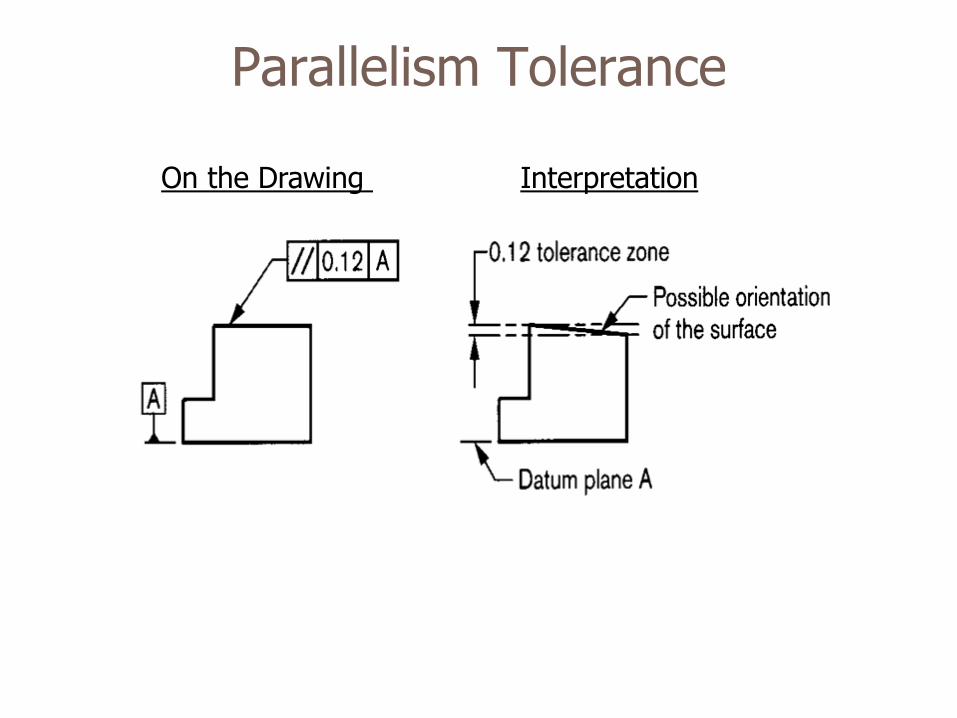
Parallelism Tolerance
On the Drawing Interpretation

Parallelism Tolerance - Planes

Parallelism Tolerance - Features
On the Drawing Interpretation

Parallelism Tolerance - Features
On the Drawing Interpretation

Perpendicularity Tolerance
On the Drawing Interpretation

Perpendicularity Tolerance

Location Tolerance
• Specifies relative Location (Attitude) between entities
• Edges, Axes, Surfaces, Features
• Always need a Datum (Reference) Plane / Feature.

Concentricity Tolerance

Material Condition Modifiers
Maximum Material Condition (MMC)
• Largest (size) shaft • Smallest (size) Hole
Symbol : M
Regardless of Feature size (RFS)

MMC – RFS Condition
ANSI/ ISO recommends
• Form of a feature is Perfect (Ideal) at MMC
• If not specified, treat Feature Tolerance as RFS.

Position Tolerance
• Controls Position (Centre or Axis) of Holes
• Needs Datums
• Primary/ Secondary/ Tertiary
• Tolerance Zone
• Circular
• Rectangular

Position Tolerance

Run Out Tolerance
• Primarily for cylindrical rotating parts
• Types of Run Out
• Circular Run Out • Total Run Out

Run Out Tolerance
Circular Total

Functional Gaging
• To test the combined effect of All tolerances
• Dimensional Tolerance • Geometric Tolerance
• Gage - Extreme Virtual Size
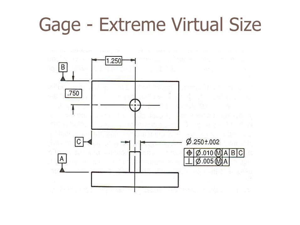
Gage - Extreme Virtual Size