geophysical survey systems, inc. antenna manuals€¦ · geophysical survey systems, inc. antenna...
TRANSCRIPT


Copyright © 2009-2017 Geophysical Survey Systems, Inc. All rights reserved including the right of reproduction in whole or in part in any form Published by Geophysical Survey Systems, Inc. 40 Simon Street Nashua, New Hampshire 03060-3075 USA Printed in the United States SIR, RADAN and UtilityScan are registered trademarks of Geophysical Survey Systems, Inc.

Geophysical Survey Systems, Inc. Antenna Manuals
Limited Warranty, Limitations Of Liability And Restrictions Geophysical Survey Systems, Inc. hereinafter referred to as GSSI, warrants that for a period of 24 months from the delivery date to the original purchaser this product will be free from defects in materials and workmanship. EXCEPT FOR THE FOREGOING LIMITED WARRANTY, GSSI DISCLAIMS ALL WARRANTIES, EXPRESS OR IMPLIED, INCLUDING ANY WARRANTY OF MERCHANTABILITY OR FITNESS FOR A PARTICULAR PURPOSE. GSSI's obligation is limited to repairing or replacing parts or equipment which are returned to GSSI, transportation and insurance pre-paid, without alteration or further damage, and which in GSSI's judgment, were defective or became defective during normal use.
GSSI ASSUMES NO LIABILITY FOR ANY DIRECT, INDIRECT, SPECIAL, INCIDENTAL OR CONSEQUENTIAL DAMAGES OR INJURIES CAUSED BY PROPER OR IMPROPER OPERATION OF ITS EQUIPMENT, WHETHER OR NOT DEFECTIVE.
Before returning any equipment to GSSI, a Return Material Authorization (RMA) number must be obtained. Please call the GSSI Customer Service Manager who will assign an RMA number. Be sure to have the serial number of the unit available
Regulatory Information The use of GSSI antennas is governed by different regulatory agencies around the world. Specific antenna models must be certified for legal operation in your country. Please read and understand the following regulatory passages that pertain to your antenna. A listing of certified antennas by region can be found www.geophysical.com/regulatoryinformation.htm.
Notice Operation is subject to the following two conditions: (1) this device may not cause interference, and (2) this device must accept any interference, including interference that may cause undesired operation of the device.
Survey Wheels All of GSSI’s antennas are designed to operate with survey wheels. Some antennas have built-in survey wheels, including the 62000 Palm Antenna and the Mini-SIR. The series of concrete antennas, including the 5100, 5101 and 52600, have survey wheels built in to their special carts, the 614 and 615. The larger antennas, including the 3101D, 5103, 50400 and 5104 are used in the larger carts, the 623 and 643, which have survey wheels built in to them. Various sizes of survey wheels can also be attached directly to these antennas. This includes the 611, 620 and 622. For highway surveys we use the 630 Distance measuring Instrument (DMI).

Geophysical Survey Systems, Inc. Antenna Manuals
Garantie limitée, limites de responsabilité et restrictions Geophysical Survey Systems, Inc, ci-après dénommé GSSI, garantit à l'acheteur original de ce produit que, pendant une période de 24 mois à compter de la date de livraison, ce dernier sera exempt de défauts de matériaux et de fabrication. EXCEPTE POUR CETTE GARANTIE LIMITÉE, GSSI REJETTE TOUTE GARANTIE, EXPLICITE OU IMPLICITE, Y COMPRIS TOUTE GARANTIE DE QUALITE MARCHANDE OU D'ADEQUATION A UN USAGE PARTICULIER. L’obligation de GSSI est limitée à la réparation ou le remplacement de pièces ou équipements qui sont retournés à GSSI, transport et assurance prépayés, sans altération ni d'autres dommages, et qui, d’après GSSI, étaient défectueux ou sont devenus défectueux lors d’une utilisation normale.
GSSI N'ASSUME AUCUNE RESPONSABILITE POUR LES DOMMAGES DIRECTS, INDIRECTS, SPÉCIAUX, INCIDENTS OU CONSEQUENTS OU BLESSURES CAUSEES PAR UNE BONNE OU MAUVAISE UTILISATION DE SON EQUIPEMENT DÉFECTUEUX OU NON.
Avant de retourner tout équipement à GSSI, une autorisation de retour matériel (RMA) doit être obtenue. Appelez s'il vous plaît le service clientèle GSSI qui attribuera un numéro de RMA. Soyez sûr d'avoir le numéro de série de l'unité.
Informations réglementaires L'utilisation des antennes GSSI est régie par différents organismes de réglementation à travers le monde. Certains modèles d'antenne spécifiques doivent être certifiés pour un fonctionnement légal dans votre pays. Merci de lire et comprendre les passages suivants de réglementation qui s'appliquent à votre antenne. Une liste des antennes certifiées par région peut être trouvée sur www.geophysical.com / regulatoryinformation.htm.
Avis La mise en œuvre est soumise aux deux conditions suivantes: (1) cet appareil ne doit pas provoquer d'interférences et (2) cet appareil doit accepter toute interférence, y compris les interférences qui peuvent causer un fonctionnement non désiré de l'appareil.
Roues codeuses – Odomètres Toutes les antennes GSSI sont conçus pour fonctionner avec des roues codeuses. Certaines antennes, comprenant l'antenne 62000 Palm et le Mini-SIR, intègrent directement les roues codeuses. La série d'antennes pour le béton, comprenant les 5100, 5101 et 52600, ont des roues codeuses intégrées à leurs chariots spéciaux, les 614 et 615. Les antennes plus grandes, telles que la 3101D, 5103, 50400 et 5104 sont utilisées dans les chariots plus grands, les 623 et 643, qui ont des roues codeuses intégrées. Différentes tailles de roues codeuses peuvent être également être fixées directement sur ces antennes, comprenant les 611, 620 et 622. Pour les auscultations de chaussées nous utilisons l’odomètre 630 (DMI : Distance Measuring Instrument).
Geophysical Survey Systems, Inc. Antenna Manuals
FCC Notice (for U.S. Customers): This device complies with part 15, class F of the FCC Rules:
Operation is subject to the following conditions:
1. This device many not cause harmful interference, and
2. This device must accept any interference received, Including interference that may cause undesired operation
Warning: Changes or modifications to this unit not expressly approved by the party responsible for compliance could void the user’s authority to operate the equipment.
Operation of this device is restricted to law enforcement, fire and rescue officials, scientific research institutes, commercial mining companies, construction companies and private parties operating on behalf of these groups. Operation by any other party is a violation of 47 U.S.C. § 301 and could subject the operator to serious legal penalties.
Coordination Requirements (a) UWB imaging systems require coordination through the FCC before the equipment may be used. The operator shall comply with any constraints on equipment usage resulting from this coordination.
(b) The users of UWB imaging devices shall supply detailed operational areas to the FCC Office of Engineering and Technology who shall coordinate this information with the Federal Government through the National Telecommunications and Information Administration. The information provided by the UWB operator shall include the name, address and other pertinent contact information of the user, the desired geographical area of operation, and the FCC ID number and other nomenclature of the UWB device. This material shall be submitted to the following address:
Frequency Coordination Branch, OET Federal Communications Commission 445 12th Street, SW Washington, D.C. 20554 ATTN: UWB Coordination (d) Users of authorized, coordinated UWB systems may transfer them to other qualified users and to different locations upon coordination of change of ownership or location to the FCC and coordination with existing authorized operations.
(e) The NTIA/FCC coordination report shall include any needed constraints that apply to day-to-day operations. Such constraints could specify prohibited areas of operations or areas located near authorized radio stations for which additional coordination is required before operation of the UWB equipment. If additional local coordination is required, a local coordination contact will be provided.
Notice: Use of this device as a wall imaging system is prohibited by FCC regulations.

Geophysical Survey Systems, Inc. Antenna Manuals

Geophysical Survey Systems, Inc. Antenna Manuals
For U.S. Customers
Ground Penetrating Radar Coordination Notice And Equipment Registration
Note: This form is only for Domestic United States users. The Federal Communications Commission (FCC) requires that all users of GPR who purchased antennas after July 15th, 2002 register their equipment and areas of operation. It is required that you fill out this form and fax or mail to the FCC.
Failure to do this is a violation of Federal law.
1. Date:
2. Company name:
3. Address:
4. Contact Information [contact name and phone number]:
5. Area Of Operation [state(s)]:
---Continued on next page.

Geophysical Survey Systems, Inc. Antenna Manuals
6. Equipment Identification:
Brand Name: Geophysical Survey Systems, Inc.
Antenna Model No. (center frequency): List all antennas being registered.
Model Frequency FCC ID (QF7 followed by Model #)
7. Receipt Date Of Equipment:
Fax this form to the FCC at: 202-418-1944
Or
Mail to:
Frequency Coordination Branch, OET Federal Communications Commission 445 12th Street, SW Washington, D.C. 20554 ATTN: UWB Coordination
Do not send this information to GSSI.

Geophysical Survey Systems, Inc. Antenna Manuals
Canadian Requirements for RSS-220
Canadian Requirements of RSS-220 for Ground Antennas This Ground Penetrating Radar Device shall be operated only when in contact with or within 1 m of the ground.
This Ground Penetrating Radar Device shall be operated only by law enforcement agencies, scientific research institutes, commercial mining companies, construction companies, and emergency rescue or firefighting organizations.
Cet appareil de radar de sol (ou géoradar) ne doit être utilisé qu’en contact avec le sol ou à 1 m maximum au dessus du sol.
Cet appareil de radar de sol ne doit être utilisé que par les forces de l’ordre, les instituts de recherche scientifiques, les sociétés minières, les sociétés de construction, et les organisations de secours d’urgence ou de combat du feu.
Canadian Requirements of RSS-220 for Hand-held Antennas This In-wall Radar Imaging Device shall be operated where the device is directed at the wall and in contact with or within 20 cm of the wall surface.
This In-wall Radar Imaging Device shall be operated only by law enforcement agencies, scientific research institutes, commercial mining companies, construction compa
nies, and emergency rescue or firefighting organizations.
Cet appareil de radar de structure (murs, poutres, dalles…) ne doit être utilisé qu’en contact avec la structure ou à 20 cm maximum décollé de cette structure.
Cet appareil de radar de sol ne doit être utilisé que par les forces de l’ordre, les instituts de recherche scientifiques, les sociétés minières, les sociétés de construction, et les organisations de secours d’urgence ou de combat du feu.
Canadian Requirements of RSS-220 for Search and Rescue Antennas This Through-wall Radar Imaging Device shall be operated only by law enforcement agencies or emergency rescue or firefighting organizations that are under a local, provincial or federal authority. The equipment is to be operated only in providing services and for necessary training operations.
Cet appareil de radar au travers des murs ne doit être utilisé que par les forces de l’ordre ou les organisations de secours d’urgence ou de combat du feu qui sont sous une autorité locale, provinciale ou fédérale. Cet équipement ne doit être utilisé que dans le cadre de services et pour les opérations d’entrainement nécessaires.
Geophysical Survey Systems, Inc. Antenna Manuals
Declaration of CE Conformance
Geophysical Survey Systems, Inc. hereby confirms that the following named products have been tested and meet the requirements of the European standards as indicated: Models: 3101A, 5106A, 52600S, 62000, MINISIR, MINIHR, LL3P, LLTRx, 41000SA, 42000S,
50400S, 51600S, 50270S, D50300/800
Description: Ground Penetrating Radar Antennas European Standards: ETSI EN 301 489-32 V1.1.1 (2005-09), ETSI EN 301 489-V1.6.1
(2005-09), ETSI EN 302 066-1 V1.1.1(2005-09), ETSI EN302 066-2 V1.1.1 (2005-09), ETSI EN 302 066-1 V1.2.1(2008-02), ETSI EN302 066-2 V1.2.1 (2008-02), ECC/DEC/(06)08
Place and Date of Issue: Intertek – ETL SEMCO 07.02.07, 03.11.09, 10.13.09, 11.18.09 Compliance Worldwide 03.23.12 09.25.12 04.14.14
Model: Profiler™ EMP-400
Description: Electromagnetic Induction System European Standards: EN61326:1997 + A1:1998 + A2:2001 Place and Date of Issue: Intertek – ETL SEMCO 08.29.06
Model: FGDC-3000/2100, StructureScan™ EZ System, StructureScan™ MINI System
Description: Ground Penetrating Radar Data Acquisition Systems European Standards: EN61000-6-2:2005, EN61000-4-2, EN61000-4-3, EN61000-4-4,
EN61000-4-5, EN61000-4-6, EN61000-4-11 Place and Date of Issue: Compliance Worldwide 09.29.09, 11.25.09
Models: SIR® 30, SIR® 30E
Description: Ground Penetrating Radar Data Acquisition System European Standards: EN61000-6-4: 2007 per EN 55011:2009 + A1:2010 Place and Date of Issue: Compliance Worldwide 07.10.12, 07.11.12
Model: SIR® 4000
Description: Ground Penetrating Radar Data Acquisition System European Standards: EN61000-6-4: 2007 per EN 55011:2009 + A1:2010 Place and Date of Issue: Compliance Worldwide 04.14.14 Chris Plumlee 1.08.15 Name of authorized person
Geophysical Survey Systems, Inc. Antenna Manuals
Table Of Contents
FCC Notice (for U.S. Customers)
Canadian Requirements for RSS-220
Declaration of CE Conformance
2600 MHz Antenna .........................................................................................................................1
2000 MHz Palm Antenna ..............................................................................................................7
1600 MHz Antenna ...................................................................................................................... 15
1000 MHz Antenna ...................................................................................................................... 21
900 MHz Antenna ........................................................................................................................ 27
400 MHz Antenna ........................................................................................................................ 33
270 MHz Antenna ........................................................................................................................ 37
200 MHz Antenna ........................................................................................................................ 41
100 MHz Antenna ........................................................................................................................ 45
16-80 MHz Antenna .................................................................................................................... 57
2 GHz Antenna .............................................................................................................................. 73
1 GHz Antenna .............................................................................................................................. 81

Geophysical Survey Systems, Inc. Antenna Manuals
Geophysical Survey Systems, Inc. Antenna Manuals
MN30-903 Rev G 1
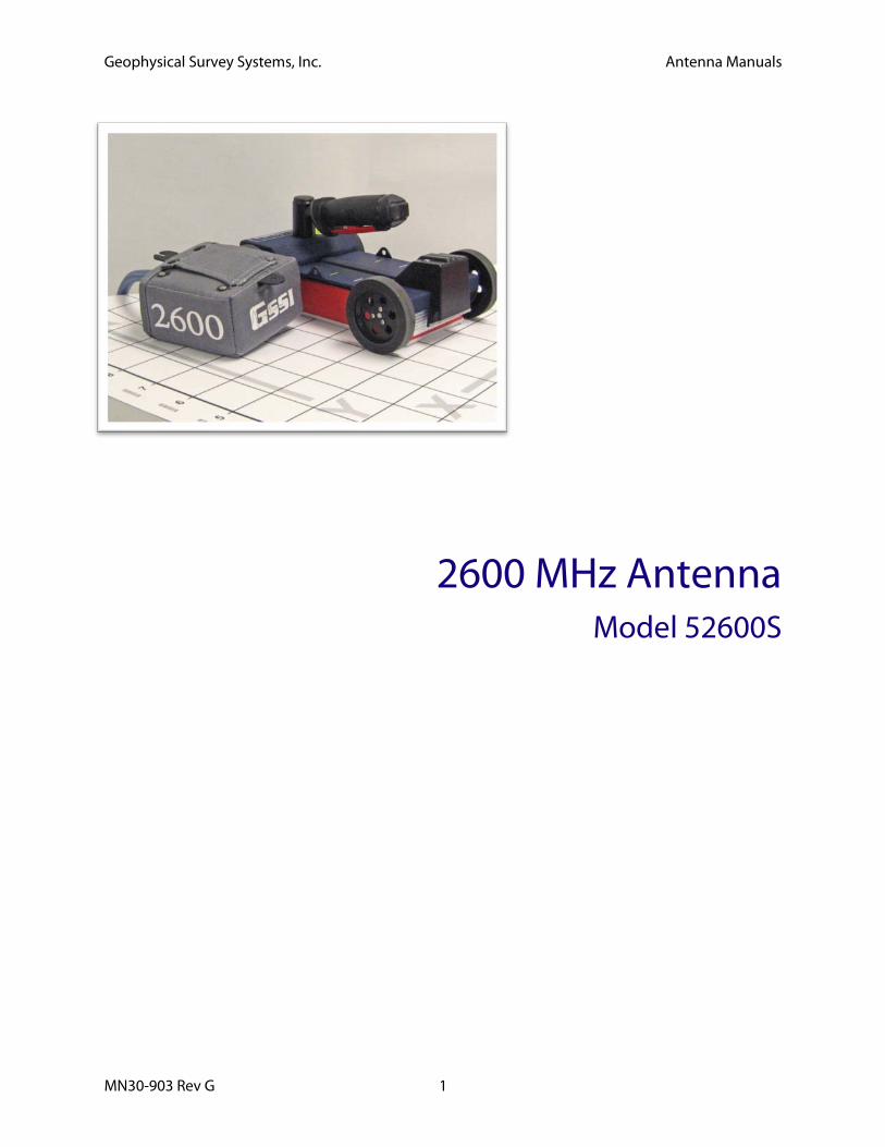
2600 MHz Antenna Model 52600S

Geophysical Survey Systems, Inc. Antenna Manuals
MN30-903 Rev G 2
Geophysical Survey Systems, Inc. 2600 MHz Antenna Model 52600S
MN30-903 Rev G 3
2600 MHz Antenna Thank you for purchasing a Model 52600S antenna. The Model 52600S represents the current state of the art in high resolution concrete structure imaging. The Model 52600S antenna has greatly improved resolution over previous high frequency antennas. Not only is the frequency higher, but the antenna has the ability to see objects at very close distances. The Model 52600S is the highest frequency ground coupled antenna available on the market today.
Note: The Model 52600 antenna cannot be used with the large, three-wheeled utility cart without the survey wheel adaptor cable. If you intend to use the antenna with the utility survey cart, contact your GSSI account representative to make sure that you have all of the necessary cabling.
Smart Antenna The Model 52600S is a 2600 MHz “smart” antenna. This antenna has a special chip in it that will work with the SIR-30 and future control units (not the SIR-3000 or SIR-20). This chip will identify the antenna to the SIR-system control unit so that the controller will be able to automatically load up the correct default settings. The 52600S will function with a SIR-3000, SIR-20 or any of GSSI’s previous controllers, but the user will need to manually set the collection parameters on the SIR-system. Collection parameters are listed below.
System Setup - Standard Settings Note: You must follow these setup instructions exactly to use the Model 52600S antenna. Positioning of the signal will be the last step in the process.
System Run Mode: Survey Wheel (recommended) or Continuous
Range: 8 ns
Number of Gain Points: 2
Vertical Low Pass FIR Filter: 5000 MHz
Vertical High Pass FIR Filter: 400 MHz
Vertical High Pass IIR Filter: 10 MHz
No Horizontal Filters
Samples per Scan: 512
Bits per Sample: 16
Transmit Rate: Set to the maximum rate allowed by the SIR System, but not higher than 200 KHz.
Scans per Second: Set to the maximum scan rate allowed by the SIR System.
Geophysical Survey Systems, Inc. 2600 MHz Antenna Model 52600S
MN30-903 Rev G 4
Signal Position Place the antenna on the concrete floor and use the Automatic Signal Position selection. You may need to try this 2 to 3 times to get the system to lock on to the surface pulse. If after 3 tries the surface pulse is not in the signal window, point the antenna into the air and again try the Automatic Position.
To test that you have the correct position, raise the antenna off the ground and you will observe on your system that the antenna transmit pulse will separate from the reflection from the ground. The higher that you raise the antenna, the further apart will be the two pulses.
Gain Check The surface pulse should be about 2/3 the width of the screen. If it is greater, reduce the Gains manually. If the signal appears too small, you can manually increase the Gains, but the first gain point should never exceed 10dB.
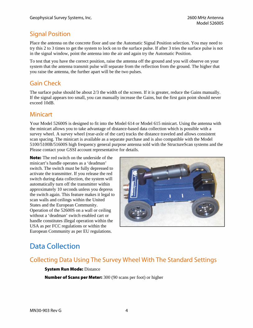
Minicart Your Model 52600S is designed to fit into the Model 614 or Model 615 minicart. Using the antenna with the minicart allows you to take advantage of distance-based data collection which is possible with a survey wheel. A survey wheel (rear-axle of the cart) tracks the distance traveled and allows consistent scan spacing. The minicart is available as a separate purchase and is also compatible with the Model 5100/5100B/51600S high frequency general purpose antenna sold with the StructureScan systems and the Please contact your GSSI account representative for details.
Note: The red switch on the underside of the minicart’s handle operates as a ‘deadman’ switch. The switch must be fully depressed to activate the transmitter. If you release the red switch during data collection, the system will automatically turn off the transmitter within approximately 10 seconds unless you depress the switch again. This feature makes it legal to scan walls and ceilings within the United States and the European Community. Operation of the 52600S on a wall or ceiling without a ‘deadman’ switch enabled cart or handle constitutes illegal operation within the USA as per FCC regulations or within the European Community as per EU regulations.
Data Collection
Collecting Data Using The Survey Wheel With The Standard Settings System Run Mode: Distance
Number of Scans per Meter: 300 (90 scans per foot) or higher
Geophysical Survey Systems, Inc. 2600 MHz Antenna Model 52600S
MN30-903 Rev G 5
Remote Operation • Pressing the thumb rocker switch button for less than one second will place a marker in the data.
• Pressing the button for longer than 6 seconds will close any open files and turn off the transmitter. To resume, the data acquisition sequence must be repeated.
Special Settings Used For Collecting Data On Bridge Decks
Setup Mode: Manual
System Run Mode: Survey Wheel
Range: 6 ns (unpaved), 10 ns (paved)
Number of Gain Points: 1
Vertical Low Pass FIR Filter: 5000 MHz
Vertical High Pass FIR Filter: 400 MHz
Vertical High Pass IIR Filter: 10 MHz
No Horizontal Filters
Samples per Scan: 512
Bits per Sample: 16
Transmit Rate: Set to the maximum scan rate allowed by the SIR System but not higher than 200 KHz.
Scans per Second: Set to the maximum scan rate allowed by the SIR System.
Signal Positioning: Use the same procedure as in standard setup
Set the Scans per Meter parameter to 80 scans per meter (24 scans per foot)
Calibrate the survey wheel before collecting data
Note: See Bridge Assessment Manual before proceeding.
Geophysical Survey Systems, Inc. 2600 MHz Antenna Model 52600S
MN30-903 Rev G 6
Specifications Center frequency: 2600 MHz
Pulse duration: 0.4 ns
Depth of penetration: 0-12 inches depending on type of concrete
Size of sensor: 1.5 x 4 x 6.5 inches (3.8 x 10 x 16.5 cm)
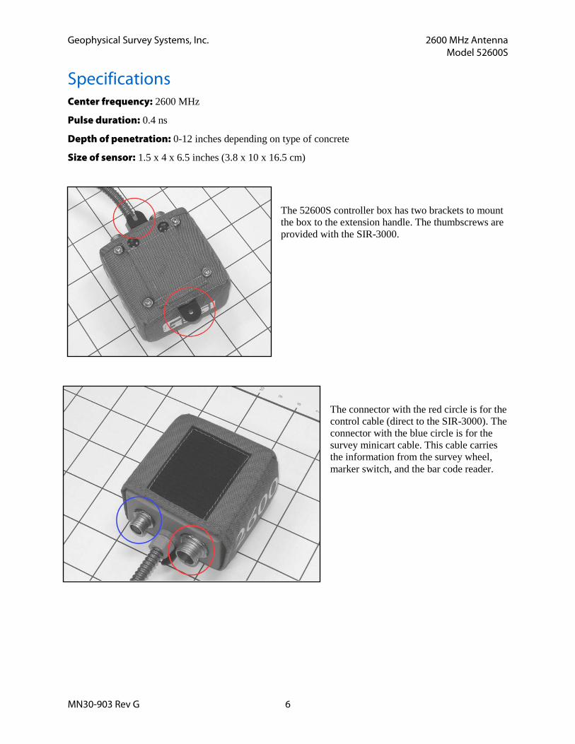
The 52600S controller box has two brackets to mount the box to the extension handle. The thumbscrews are provided with the SIR-3000.
The connector with the red circle is for the control cable (direct to the SIR-3000). The connector with the blue circle is for the survey minicart cable. This cable carries the information from the survey wheel, marker switch, and the bar code reader.
MN30-903 Rev G 7
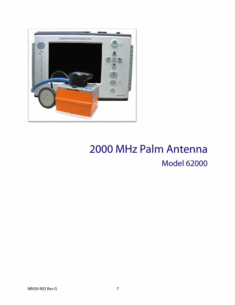
2000 MHz Palm Antenna Model 62000

MN30-903 Rev G 8
Geophysical Survey Systems, Inc. 2000 MHz Palm Antenna Model 62000
MN30-903 Rev G 9
2000 MHz Palm Antenna Thank you for purchasing the Model 62000, 2000 MHz Palm Antenna. The Palm Antenna combines exceptionally fine resolution in a small package. Its small size will help the concrete scanning professional to get into areas which are too tight for conventional antennas.
The Palm antenna incorporates an integrated survey wheel which can change position and allow you to use the antenna in a cross-polarized configuration to aid in the detection of non-metallic objects. The Palm antenna also comes with an integrated control cable with a length of 7 m (22.75 feet). There is also an antenna safety attachment point 1.5 m (5 feet) from the antenna. If you are working high above the ground, GSSI recommends attaching the safety point to your belt so that the antenna will not be damaged if you drop it.
The Palm antenna is backward compatible with previous GSSI SIR Systems.
Note: The indented vertical lines on the sides of the antenna housing denote the center of the antenna. When marking locations on the concrete, this is the reference point on the antenna to mark.
System Setup - Standard Settings Note: You must follow these setup instructions exactly to use the Model 62000 antenna. Positioning of the signal will be the last step in the process.
Setup Mode: Manual
System Run Mode: Survey Wheel (recommended) or Continuous
Range: 5-8 ns
Scans/foot (meter): 90 (300)
Number of Gain Points: 4, Auto Gain
Vertical Low Pass FIR Filter: 4000 MHz
Vertical High Pass FIR Filter: 500 MHz
Vertical High Pass IIR Filter: 10 MHz
Samples per Scan: 256 or 512
Bits per Sample: 16
Scans per Second: Set to the maximum scan rate allowed by the SIR System used
Geophysical Survey Systems, Inc. 2000 MHz Palm Antenna Model 62000
MN30-903 Rev G 10
“Deadman” Switch Operation (IMPORTANT!) In order to comply with various emissions standards imposed by various governments, the Palm antenna incorporates a “Deadman” switch which will turn off the transmitter when the operator is not using the antenna. The Palm antenna incorporates two “Deadman” devices: the blue button on the top of the antenna housing and the survey wheel. When neither of these is used, the antenna will shut off after 10 seconds. It will resume instantly if the survey wheel is moved or the button is pressed.
You must hold down the Blue button whenever the SIR-3000 System is doing the following:
1 Booting from the initial logo screen into your chosen data collection application (TerraSIRch, ConcreteScan, Quick3D)
2 Changing any collection parameter (Depth, Range, Filters, Position, Dielectric, Sampling Density, Gains).
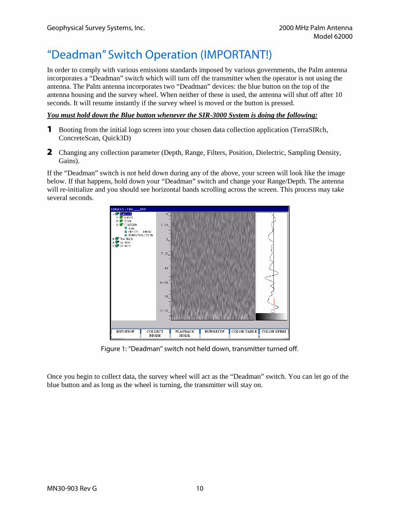
If the “Deadman” switch is not held down during any of the above, your screen will look like the image below. If that happens, hold down your “Deadman” switch and change your Range/Depth. The antenna will re-initialize and you should see horizontal bands scrolling across the screen. This process may take several seconds.
Figure 1: “Deadman” switch not held down, transmitter turned off.
Once you begin to collect data, the survey wheel will act as the “Deadman” switch. You can let go of the blue button and as long as the wheel is turning, the transmitter will stay on.
Geophysical Survey Systems, Inc. 2000 MHz Palm Antenna Model 62000
MN30-903 Rev G 11
Signal Position 1 Place the antenna on the concrete floor and use the Automatic Signal Position selection.
• If you are in ConcreteScan, this is done by pressing the Run/Stop button twice.
• If you are in TerraSIRch, go to Collect>Position> and toggle from Auto to Manual and then back to Auto.
• You may need to try this 2 to 3 times to get the system to lock on to the surface pulse. If after 3 tries the surface reflection is not in the signal window, point the antenna into the air and again try the Automatic Position.
2 To test that you have the correct position, raise the antenna off the ground and you will observe on your system that the antenna transmit waveform will separate from the reflection from the ground. The higher that you raise the antenna, the further apart will be the two waveforms.
Gain Check GSSI recommends allowing the SIR System to automatically set gain levels. Place the antenna in contact with the concrete so that the SIR System sets values which are appropriate for the material. Be sure to hold down the “Deadman” switch while re-initializing the gains.
The Marker Switch The black button on the top of the antenna housing is a remote marker switch. Pushing this while collecting data will put a user mark in the data. This is useful for situations when you want to record the location of a surface feature or other important item in the data.
Integrated Survey Wheel Your Palm antenna incorporates a survey wheel for collecting data in Distance (Survey Wheel) mode. While it is still possible to collect Continuous (Time based) data with the Palm antenna, the survey wheel cannot be removed from the antenna.
GSSI recommend calibrating the survey wheel by following the instructions presented in your SIR-System manual. For convenience the calibration value is approximately 6750 counts/foot (22,146 counts/m). Note that this value is subject to change and you should calibrate your own survey wheel for accuracy.
The survey wheel can be moved to the side of the antenna in order to collect data with the antenna elements in the cross-polarized configuration. Please see the GSSI Handbook for RADAR Inspection of Concrete for a discussion of the benefits of this technique.
Geophysical Survey Systems, Inc. 2000 MHz Palm Antenna Model 62000
MN30-903 Rev G 12
To Change the Wheel Position
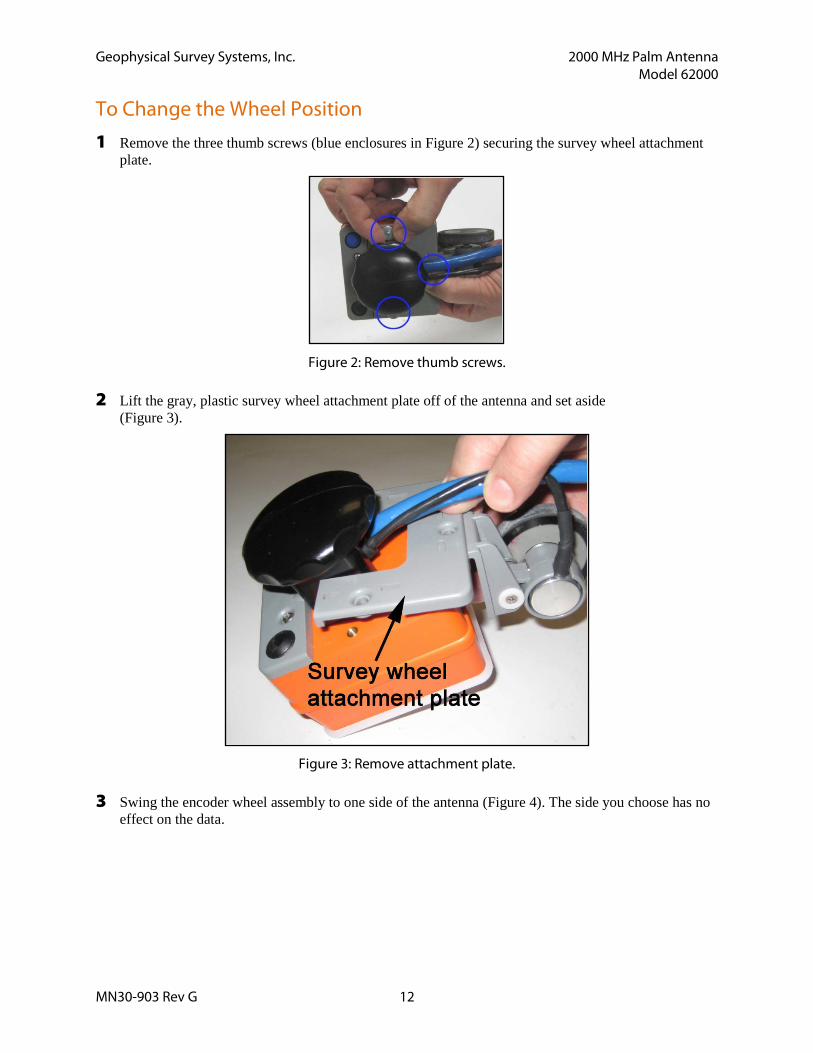
1 Remove the three thumb screws (blue enclosures in Figure 2) securing the survey wheel attachment plate.
Figure 2: Remove thumb screws.
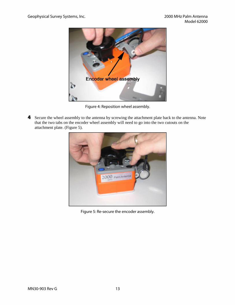
2 Lift the gray, plastic survey wheel attachment plate off of the antenna and set aside (Figure 3).
Figure 3: Remove attachment plate.
3 Swing the encoder wheel assembly to one side of the antenna (Figure 4). The side you choose has no effect on the data.
Geophysical Survey Systems, Inc. 2000 MHz Palm Antenna Model 62000
MN30-903 Rev G 13
Figure 4: Reposition wheel assembly.
4 Secure the wheel assembly to the antenna by screwing the attachment plate back to the antenna. Note that the two tabs on the encoder wheel assembly will need to go into the two cutouts on the attachment plate. (Figure 5).
Figure 5: Re-secure the encoder assembly.
Geophysical Survey Systems, Inc. 2000 MHz Palm Antenna Model 62000
MN30-903 Rev G 14
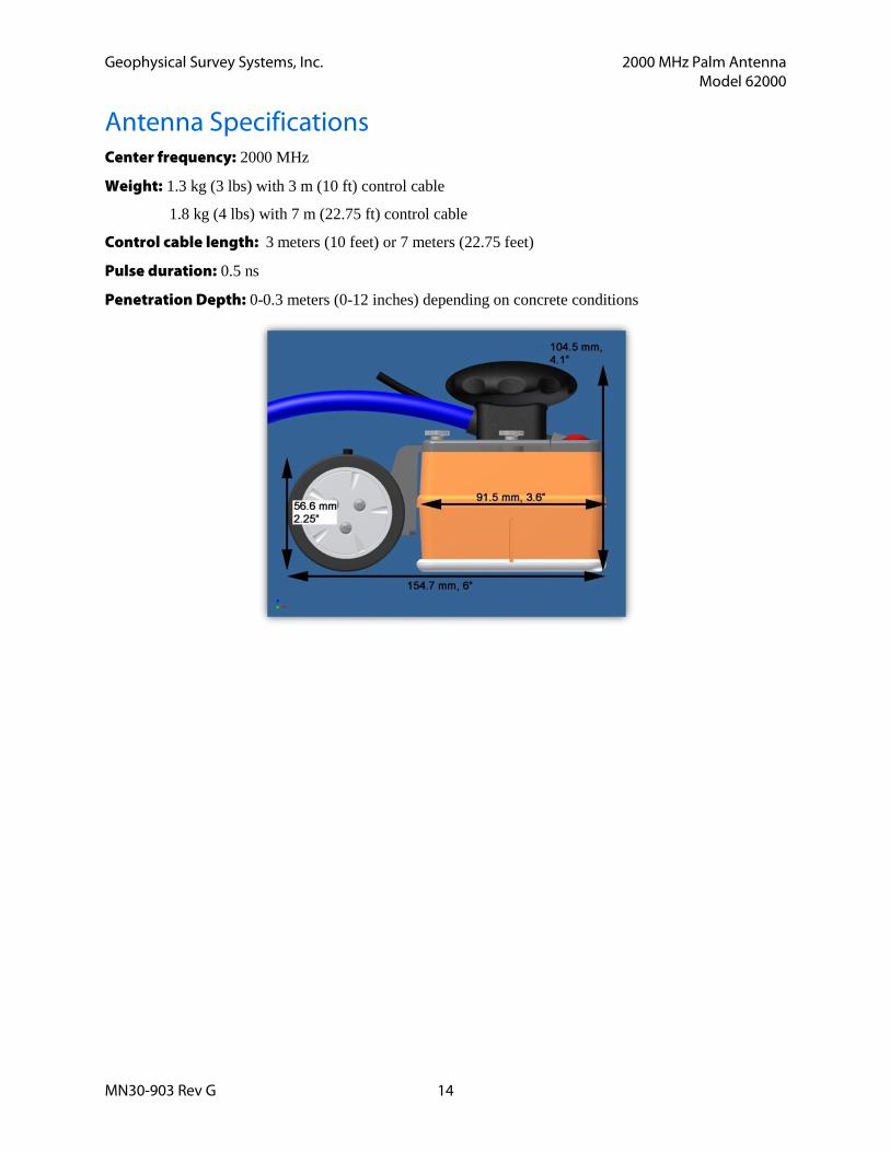
Antenna Specifications Center frequency: 2000 MHz
Weight: 1.3 kg (3 lbs) with 3 m (10 ft) control cable
1.8 kg (4 lbs) with 7 m (22.75 ft) control cable
Control cable length: 3 meters (10 feet) or 7 meters (22.75 feet)
Pulse duration: 0.5 ns
Penetration Depth: 0-0.3 meters (0-12 inches) depending on concrete conditions
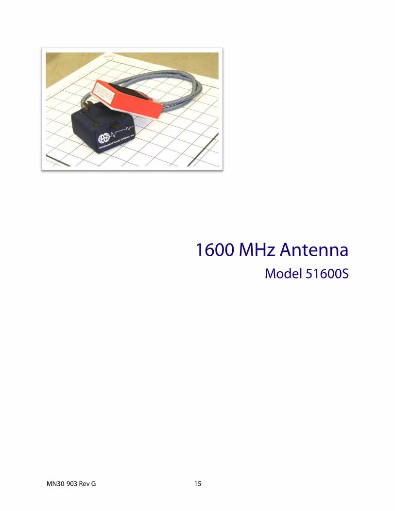
MN30-903 Rev G 15
1600 MHz Antenna Model 51600S

MN30-903 Rev G 16

Geophysical Survey Systems, Inc. 1600 MHz Antenna Model 51600S
MN30-903 Rev G 17
1600 MHz Antenna The Model 51600S antenna has greatly improved performance over previous high frequency antennas. Not only is the frequency higher, but the antenna has the ability to see objects at very close distances.
Note: The Model 51600S antenna cannot be used with the large, three-wheeled utility cart. It can only be used with the small survey minicarts. If you want to use the 51600S for data collection on bridge decks, you should use that small minicart and the extension arm.
Smart Antenna The Model 51600S is a 1600 MHz “smart” antenna. This antenna has a special chip in it that will work with the SIR-30 and future control units (not the SIR-3000 or SIR-20). This chip will identify the antenna to the SIR-system control unit so that the controller will be able to automatically load up the correct default settings. The 51600S will function with a SIR-3000, SIR-20 or any of GSSI’s previous controllers, but the user will need to manually set the collection parameters on the SIR-system.
System Setup - Standard Settings Note: You must follow these setup instructions exactly to use the Model 51600S antenna. Positioning of the signal will be the last step in the process.
Setup Mode: Manual
System Run Mode: Survey Wheel (recommended) or Continuous
Range: 6-12 ns
Number of Gain Points: 3
Vertical Low Pass Filter: 3000 MHz
Vertical High Pass Filter: 400 MHz
Samples per Scan: 512
Bits per Sample: 16
Scans per Second: Set to the maximum scan rate allowed by the SIR System used
Signal Position Place the antenna on the concrete floor and use the Automatic Signal Position selection. You may need to try this 2 to 3 times to get the system to lock on to the surface pulse. If after 3 tries the surface pulse is not in the signal window, point the antenna into the air and again try the Automatic Position.
To test that you have the correct position, raise the antenna off the ground and you will observe on your system that the antenna transmit pulse will separate from the reflection from the ground. The higher that you raise the antenna, the further apart will be the two pulses.
Geophysical Survey Systems, Inc. 1600 MHz Antenna Model 51600S
MN30-903 Rev G 18
Gain Check The surface pulse should be about 2/3 the width of the screen. If it is greater, reduce the Gains manually. If the signal appears too small you can manually increase the Gains, but the first gain point should never exceed 10dB.
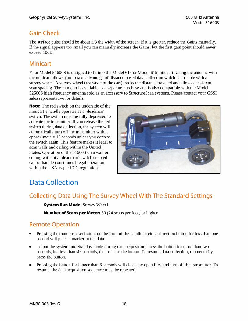
Minicart Your Model 51600S is designed to fit into the Model 614 or Model 615 minicart. Using the antenna with the minicart allows you to take advantage of distance-based data collection which is possible with a survey wheel. A survey wheel (rear-axle of the cart) tracks the distance traveled and allows consistent scan spacing. The minicart is available as a separate purchase and is also compatible with the Model 52600S high frequency antenna sold as an accessory to StructureScan systems. Please contact your GSSI sales representative for details.
Note: The red switch on the underside of the minicart’s handle operates as a ‘deadman’ switch. The switch must be fully depressed to activate the transmitter. If you release the red switch during data collection, the system will automatically turn off the transmitter within approximately 10 seconds unless you depress the switch again. This feature makes it legal to scan walls and ceiling within the United States. Operation of the 51600S on a wall or ceiling without a ‘deadman’ switch enabled cart or handle constitutes illegal operation within the USA as per FCC regulations.
Data Collection
Collecting Data Using The Survey Wheel With The Standard Settings System Run Mode: Survey Wheel
Number of Scans per Meter: 80 (24 scans per foot) or higher
Remote Operation • Pressing the thumb rocker button on the front of the handle in either direction button for less than one
second will place a marker in the data.
• To put the system into Standby mode during data acquisition, press the button for more than two seconds, but less than six seconds, then release the button. To resume data collection, momentarily press the button.
• Pressing the button for longer than 6 seconds will close any open files and turn off the transmitter. To resume, the data acquisition sequence must be repeated.

Geophysical Survey Systems, Inc. 1600 MHz Antenna Model 51600S
MN30-903 Rev G 19
Special Settings Used For Collecting Data On Bridge Decks
Setup Mode: Manual
System Run Mode: Survey Wheel
Range: 6 ns (unpaved), 10 ns (paved)
Number of Gain Points: 1
Vertical Low Pass Filter: 3000 MHz
Vertical High Pass Filter: 250 MHz
No Horizontal Filters
Samples per Scan: 512
Bits per Sample: 16
Scans per Second: Set to the maximum scan rate allowed by the SIR System used
Signal Positioning: Use the same procedure as in standard setup
Set the Scans per Meter parameter to 80 scans per meter (24 scans per foot)
Calibrate the survey wheel before collecting data
Note: See Bridge Assessment Manual before proceeding.
Geophysical Survey Systems, Inc. 1600 MHz Antenna Model 51600S
MN30-903 Rev G 20
Specifications Center frequency: 1600 MHz
Pulse duration: 0.7 ns
Depth of penetration: 0-18 inches depending on type of concrete
Size of sensor: 1.5 x 4 x 6.5 inches (3.8 x 10 x 16.5 cm)
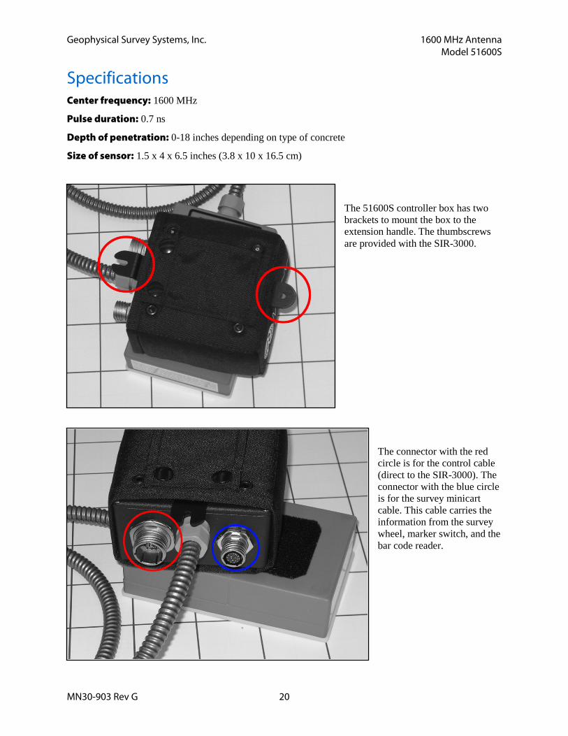
The 51600S controller box has two brackets to mount the box to the extension handle. The thumbscrews are provided with the SIR-3000.
The connector with the red circle is for the control cable (direct to the SIR-3000). The connector with the blue circle is for the survey minicart cable. This cable carries the information from the survey wheel, marker switch, and the bar code reader.
MN30-903 Rev G 21
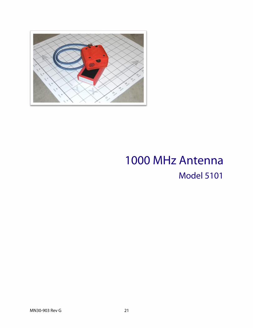
1000 MHz Antenna Model 5101

MN30-903 Rev G 22
Geophysical Survey Systems, Inc. 1000 MHz Antenna Model 5101
MN30-903 Rev G 23
1000 MHz Antenna The Model 5101 antenna represents the state of the art in shallow earth or deeper concrete imaging. The high frequency allows excellent resolution at a penetration depth that is greater than antennas in the 1.5 GHz range. This antenna is appropriate in areas where higher frequencies do not have adequate penetration power and lower frequencies do not provide acceptable resolution.
Please note that the Model 5101 antenna has been discontinued Summer, 2013.
Note: The Model 5101 antenna cannot at present be used with the large, three-wheeled utility cart. It can only be used with the small survey minicarts. Use of the Model 5101 for data collection on bridge decks requires the small minicart (Model 614 or 615) and the extension arm.
System Setup - Standard Settings Note: You must follow these setup instructions exactly to use the Model 5101 antenna. Positioning of the signal will be the last step in the process.
Setup Mode: Manual
System Run Mode: Survey Wheel (recommended) or Continuous
Range: 20-40 ns
Number of Gain Points: 5
Vertical Low Pass Filter (FIR): 3000 MHz
Vertical High Pass Filter (FIR): 225 to 250 MHz
Vertical High Pass Filter (IIR): 10 MHz
Samples per Scan: 512
Bits per Sample: 16
Scans per Second: Set to the maximum scan rate allowed by the SIR System used
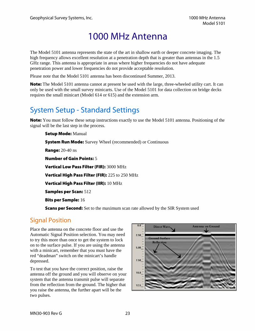
Signal Position Place the antenna on the concrete floor and use the Automatic Signal Position selection. You may need to try this more than once to get the system to lock on to the surface pulse. If you are using the antenna with a minicart, remember that you must have the red “deadman” switch on the minicart’s handle depressed.
To test that you have the correct position, raise the antenna off the ground and you will observe on your system that the antenna transmit pulse will separate from the reflection from the ground. The higher that you raise the antenna, the further apart will be the two pulses.
Geophysical Survey Systems, Inc. 1000 MHz Antenna Model 5101
MN30-903 Rev G 24
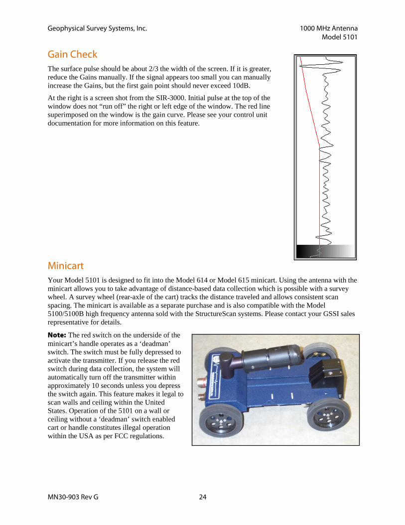
Gain Check The surface pulse should be about 2/3 the width of the screen. If it is greater, reduce the Gains manually. If the signal appears too small you can manually increase the Gains, but the first gain point should never exceed 10dB.
At the right is a screen shot from the SIR-3000. Initial pulse at the top of the window does not “run off” the right or left edge of the window. The red line superimposed on the window is the gain curve. Please see your control unit documentation for more information on this feature.
Minicart Your Model 5101 is designed to fit into the Model 614 or Model 615 minicart. Using the antenna with the minicart allows you to take advantage of distance-based data collection which is possible with a survey wheel. A survey wheel (rear-axle of the cart) tracks the distance traveled and allows consistent scan spacing. The minicart is available as a separate purchase and is also compatible with the Model 5100/5100B high frequency antenna sold with the StructureScan systems. Please contact your GSSI sales representative for details.
Note: The red switch on the underside of the minicart’s handle operates as a ‘deadman’ switch. The switch must be fully depressed to activate the transmitter. If you release the red switch during data collection, the system will automatically turn off the transmitter within approximately 10 seconds unless you depress the switch again. This feature makes it legal to scan walls and ceiling within the United States. Operation of the 5101 on a wall or ceiling without a ‘deadman’ switch enabled cart or handle constitutes illegal operation within the USA as per FCC regulations.

Geophysical Survey Systems, Inc. 1000 MHz Antenna Model 5101
MN30-903 Rev G 25
Data Collection Consult your control unit documentation for instructions on configuring your GPR system to collect data with the Model 5101.
Collecting Data Using the Survey Wheel with the Standard Settings System Run Mode: Survey Wheel (Distance)
Number of Scans per Meter: 200 (60 scans per foot) or higher
Remote Operation on the Survey Minicart • Pressing the thumb rocker button for less than one second will place a marker in the data.
• Pressing the button for longer than 6 seconds will close any open files and turn off the transmitter. To resume, the data acquisition sequence must be repeated.
Special Settings Used For Collecting Data on Bridge Decks
Setup Mode: Manual
System Run Mode: Survey Wheel
Range: 6 ns (unpaved), 10 ns (paved)
Number of Gain Points: 1
Vertical Low Pass Filter: 3000 MHz
Vertical High Pass Filter: 225 to 250 MHz
Vertical High Pass Filter (IIR): 10 MHz
No Horizontal Filters
Samples per Scan: 512
Bits per Sample: 16
Scans per Second: Set to the maximum scan rate allowed by the SIR System used
Signal Positioning: Use the same procedure as in standard setup
Set the Scans per Meter parameter to 80 scans per meter (24 scans per foot)
Calibrate the survey wheel before collecting data
Note: See Bridge Assessment Manual before proceeding.

Geophysical Survey Systems, Inc. 1000 MHz Antenna Model 5101
MN30-903 Rev G 26
Specifications Center frequency: 1000 MHz
Pulse duration: 1 ns
Depth of penetration: 0-30 inches depending on type of concrete
Size of sensor: 1.5 x 4 x 6.5 inches (3.8 x 10 x 16.5 cm)
The 5101 controller box has two brackets to mount the box to the extension handle. The thumbscrews are provided with the SIR-3000.
The connector with the red circle is for the control cable (direct to the SIR-3000). The connector with the blue circle is for the survey minicart cable. This cable carries the information from the survey wheel, marker switch, and the bar code reader.

MN30-903 Rev G 27
900 MHz Antenna Model 3101 Series

MN30-903 Rev G 28

Geophysical Survey Systems, Inc. 900 MHz Antenna Model 3101 Series
MN30-903 Rev G 29
900 MHz Antenna Thank you for purchasing a GSSI 3101 series antenna. This series includes the Model 3101A and the Model 3101D. The Model 3101 series antenna is a high frequency antenna that is designed for applications requiring very fine resolution and shallow depth penetration in a variety of materials. Please take a moment to examine your shipment to familiarize yourself with this manual. If you need assistance, GSSI technical support can be reached Monday-Friday, 8am- 5pm, US Eastern Time at (800) 524-3011, or at (603) 893-1109 (International). You can also access technical support on the web at www.geophysical.com.
Note: The Model 3101D antenna is for use and sale within the United States. It has been tested by the FCC and conforms to FCC emissions standards. The Model 3101A is for use and sale outside of the United States. The 3101A has not been tested by the FCC and it is illegal to operate the 3101A within the United States.
The Model 3101 Series can be used in continuous, survey wheel or static stacking modes. Please consult your control unit documentation for instructions on configuring your system for data collection modes.
System Setup - Standard Settings
Preset Settings: System Run Mode: Survey Wheel (recommended) or Continuous Range: 15 ns Number of Gain Points: 3 Vertical Low Pass Filter: 2500 MHz Vertical High Pass Filter: 225 MHz Samples per Scan: 512 Bits per Sample: 16 Scans per Second: Set to 64 (increase to 120 when using survey wheel).
Deeper Profiling: Setup Mode: Manual System Run Mode: Survey Wheel (recommended) or Continuous Range: 30 – 50 ns Number of Gain Points: 3 Vertical Low Pass Filter: 2500 MHz Vertical High Pass Filter: 225 MHz Samples per Scan: 512 Bits per Sample: 16 Scans per Second: to 64 (increase to 120 when using survey wheel).
Geophysical Survey Systems, Inc. 900 MHz Antenna Model 3101 Series
MN30-903 Rev G 30
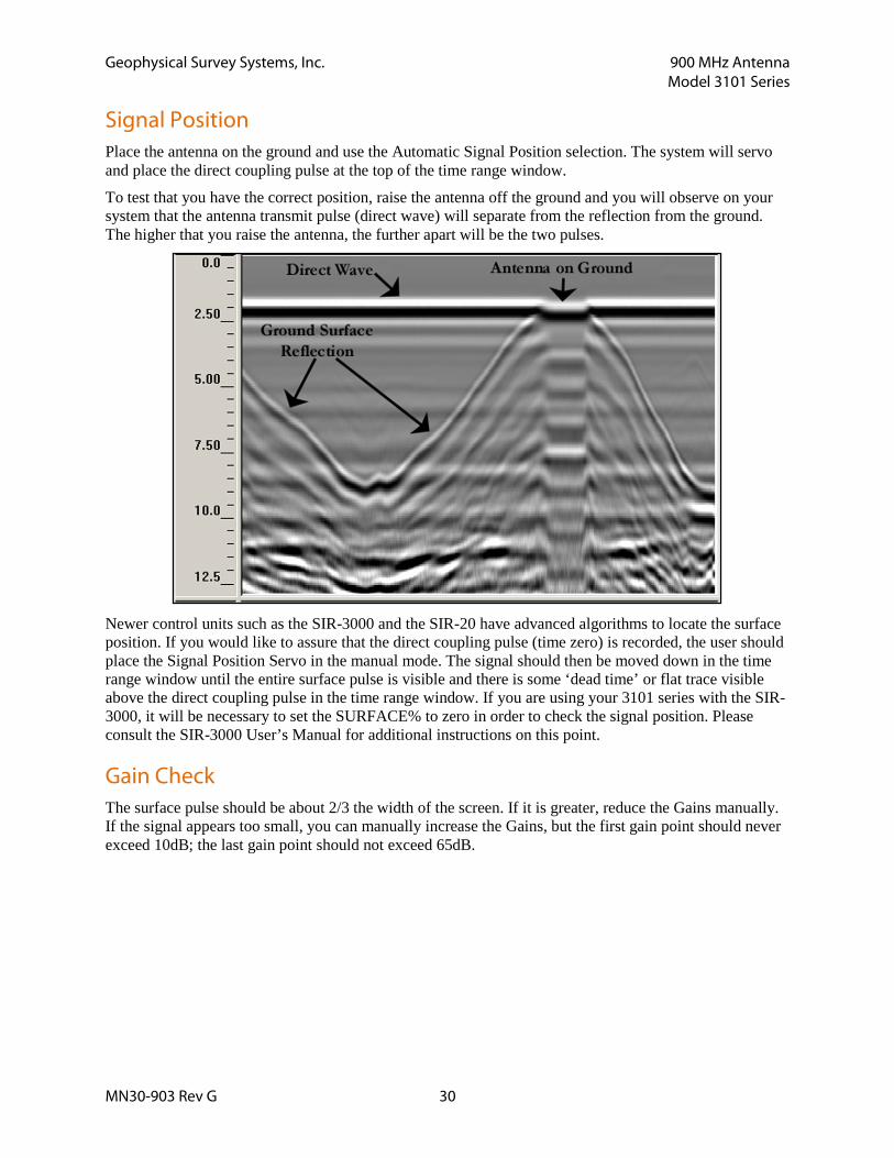
Signal Position Place the antenna on the ground and use the Automatic Signal Position selection. The system will servo and place the direct coupling pulse at the top of the time range window.
To test that you have the correct position, raise the antenna off the ground and you will observe on your system that the antenna transmit pulse (direct wave) will separate from the reflection from the ground. The higher that you raise the antenna, the further apart will be the two pulses.
Newer control units such as the SIR-3000 and the SIR-20 have advanced algorithms to locate the surface position. If you would like to assure that the direct coupling pulse (time zero) is recorded, the user should place the Signal Position Servo in the manual mode. The signal should then be moved down in the time range window until the entire surface pulse is visible and there is some ‘dead time’ or flat trace visible above the direct coupling pulse in the time range window. If you are using your 3101 series with the SIR-3000, it will be necessary to set the SURFACE% to zero in order to check the signal position. Please consult the SIR-3000 User’s Manual for additional instructions on this point.
Gain Check The surface pulse should be about 2/3 the width of the screen. If it is greater, reduce the Gains manually. If the signal appears too small, you can manually increase the Gains, but the first gain point should never exceed 10dB; the last gain point should not exceed 65dB.

Geophysical Survey Systems, Inc. 900 MHz Antenna Model 3101 Series
MN30-903 Rev G 31
Using Your 3101 Series Antenna with a Survey Wheel By using a survey wheel with your antenna you can more easily relocate targets to the survey surface, and perform distance-based processing functions in RADAN without having to distance normalize your data.
Survey wheels are available as a separate purchase. If you do not already own one, please contact your GSSI Sales Representative to discuss the features and benefits of each type. The survey wheel calibration values shown below are only approximations. The user should calibrate the survey wheel for most accurate location data.
Model 611 (3 5/6” wheel) Ticks/foot: 609.6
Ticks/meter: 2000
To attach the 611, simply undo the four screws holding the antenna’s tow handle bracket and sandwich that 611 bracket plate between the antenna and the tow handle bracket. Replace the four screws to secure.
Model 62X Survey Cart Ticks/foot (approx.): -544
Ticks/meter (approx.): -1767
The 3101 can be placed in the white plastic antenna holder of the 62X cart for use on rougher terrain or for large area surveys.
Note: Due to size limitations, a regular, straight connector control cable will not fit the 3101 and the 62X cart. Be sure that you have a control cable with a 90 degree connector on the antenna end. GSSI makes a 2-meter control cable with a 90 degree connector that is designed specifically to work with this cart. It is GSSI part number FGCB025/19R-11LPR. Please contact your GSSI sales representative for pricing and availability.
Model 65X Survey Cart Ticks/foot (approx.): 1225
Ticks/meter (approx.): 4030
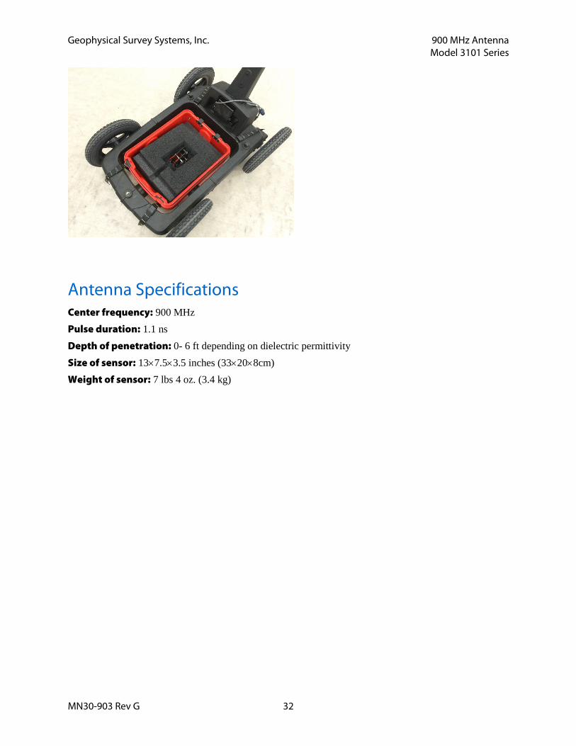
The 900 MHz antenna can also be used in the smaller 4-wheeled utility cart. GSSI supplies a foam insert to keep the antenna stabilized in the cart capsule. Please contact your GSSI sales representative for details.
Geophysical Survey Systems, Inc. 900 MHz Antenna Model 3101 Series
MN30-903 Rev G 32
Antenna Specifications Center frequency: 900 MHz Pulse duration: 1.1 ns Depth of penetration: 0- 6 ft depending on dielectric permittivity Size of sensor: 13×7.5×3.5 inches (33×20×8cm) Weight of sensor: 7 lbs 4 oz. (3.4 kg)
MN30-903 Rev G 33
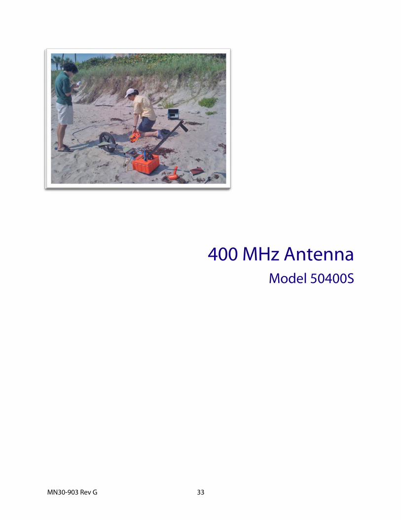
400 MHz Antenna Model 50400S

MN30-903 Rev G 34

Geophysical Survey Systems, Inc. 400 MHz Antenna Model 50400S
MN30-903 Rev G 35
400 MHz Antenna The Model 50400S antenna has greatly improved resolution performance over previous GSSI mid-frequency antennas, such as the Model 3105 (300 MHz). The Model 50400S can be used in continuous, survey wheel or static stacking modes.
Smart Antenna The Model 50400S is a 400 MHz “smart” antenna. This antenna has a special chip in it that will work with the SIR-30 and future control units (not the SIR-3000 or SIR-20). This chip will identify the antenna to the SIR-system control unit so that the controller will be able to automatically load up the correct default settings. The 50400S will function with a SIR-3000, SIR-20 or any of GSSI’s previous controllers, but the user will need to manually set the collection parameters on the SIR-system.
System Setup - Standard Settings
Preset Settings: Range/Depth is approximately 2.5m (8 ft) assuming a dielectric constant of 9.
Setup Mode: Manual
System Run Mode: Survey Wheel (recommended) or Continuous
Range: 50 ns
Number of Gain Points: 5
Vertical Low Pass Filter: 800 MHz
Vertical High Pass Filter: 100 MHz
Samples per Scan: 512
Bits per Sample: 16
Scans per Second: Set to 120 (recommended).
Geophysical Survey Systems, Inc. 400 MHz Antenna Model 50400S
MN30-903 Rev G 36
Deep Profiling: For approximately 5 m (16 ft) with a dielectric of 9.
Setup Mode: Manual
System Run Mode: Survey Wheel (recommended) or Continuous
Range: 100 ns
Number of Gain Points: 5
Vertical Low Pass Filter: 800 MHz
Vertical High Pass Filter: 100 MHz
Samples per Scan: 1024
Bits per Sample: 16
Scans per Second: Set to 120 (recommended).
Signal Position Place the antenna on the ground and use the Automatic Signal Position selection. The system will servo and place the direct coupling pulse at the top of the time range window.
To test that you have the correct position, raise the antenna off the ground and you will observe on your system that the antenna transmit pulse will separate from the reflection from the ground. The higher that you raise the antenna, the further apart will be the two pulses.
To assure that the direct coupling pulse (time zero) is recorded the user should place the signal Position servo in the manual mode. The signal should then be moved down in the time range window until the entire surface pulse is visible and there is some ‘dead time’ or flat trace visible above the direct coupling pulse in the time range window.
Gain Check The surface pulse should be about 2/3 the width of the screen. If it is greater, reduce the Gains manually. If the signal appears too small you can manually increase the Gains, but the first gain point should never exceed 10dB, the last gain point should not exceed 65dB.
Specifications Center frequency: 400 MHz
Pulse duration: 2.5 ns
Depth of penetration: 0-16 ft depending on dielectric permittivity
Size of sensor: 12×12×6.5 inches (30×30×17cm)
Weight of sensor: 14 lbs (6.4 kg)

MN30-903 Rev G 37
270 MHz Antenna Model 50270S

MN30-903 Rev G 38

Geophysical Survey Systems, Inc. 270 MHz Antenna Model 50270S
MN30-903 Rev G 39
270 MHz Antenna The Model 50270S antenna has greatly improved resolution performance over previous GSSI mid-frequency antennas, such as the Model 3105 (300 MHz). The Model 5104 can be used in continuous, survey wheel or static stacking modes. The Model 50270S has a center frequency of 270 MHz when measured in air.
Smart Antenna The Model 50270S is a 270 MHz “smart” antenna. This antenna has a special chip in it that will work with the SIR-30 and future control units (not the SIR-3000 or SIR-20). This chip will identify the antenna to the SIR-system control unit so that the controller will be able to automatically load up the correct default settings. The 50270S will function with a SIR-3000, SIR-20 or any of GSSI’s previous controllers, but the user will need to manually set the collection parameters on the SIR-system.
System Setup - Standard Settings Shallow Profiling: (SIR-3000 preset)
Setup Mode: Manual
System Run Mode: Survey Wheel (recommended) or Continuous
Range: 75 ns
Number of Gain Points: 3
Vertical Low Pass Filter: 700 MHz
Vertical High Pass Filter: 75 MHz
Samples per Scan: 512
Bits per Sample: 16
Scans per Second: Set to maximum scan rate allowed by the SIR System used..
Deep Profiling: (Recommend manual setup) Setup Mode: Manual
System Run Mode: Survey Wheel (recommended) or Continuous
Range: 175 ns
Number of Gain Points: 5
Vertical Low Pass Filter: 700 MHz
Vertical High Pass Filter: 75 MHz
Samples per Scan: 1024
Bits per Sample: 16
Scans per Second: Set to maximum scan rate allowed by the SIR System used.
Geophysical Survey Systems, Inc. 270 MHz Antenna Model 50270S
MN30-903 Rev G 40
Signal Position Place the antenna on the ground and use the Automatic Signal Position selection. The system will servo and place the direct coupling pulse at the top of the time range window.
To test that you have the correct position, raise the antenna off the ground and you will observe on your system that the antenna transmit pulse will separate from the reflection from the ground. The higher that you raise the antenna, the further apart will be the two pulses.
To assure that the direct coupling pulse (time zero) is recorded the user should place the signal Position servo in the manual mode. The signal should then be moved down in the time range window until the entire surface pulse is visible and there is some ‘dead time’ or flat trace visible above the direct coupling pulse in the time range window.
Gain Check The surface pulse should be about 2/3 the width of the screen. If it is greater, reduce the Gains manually. If the signal appears too small you can manually increase the Gains, but the first gain point should never exceed 10dB, the last gain point should not exceed 65dB.
Specifications Center frequency: 270 MHz
Pulse duration: 3.6 ns
Depth of penetration: 0-25 ft depending on dielectric permittivity
Size of sensor: 17.5×17.5×7.5 inches (44.5×44.5×19cm)
Weight of sensor: 19 lbs (8.6 kg)
MN30-903 Rev G 41
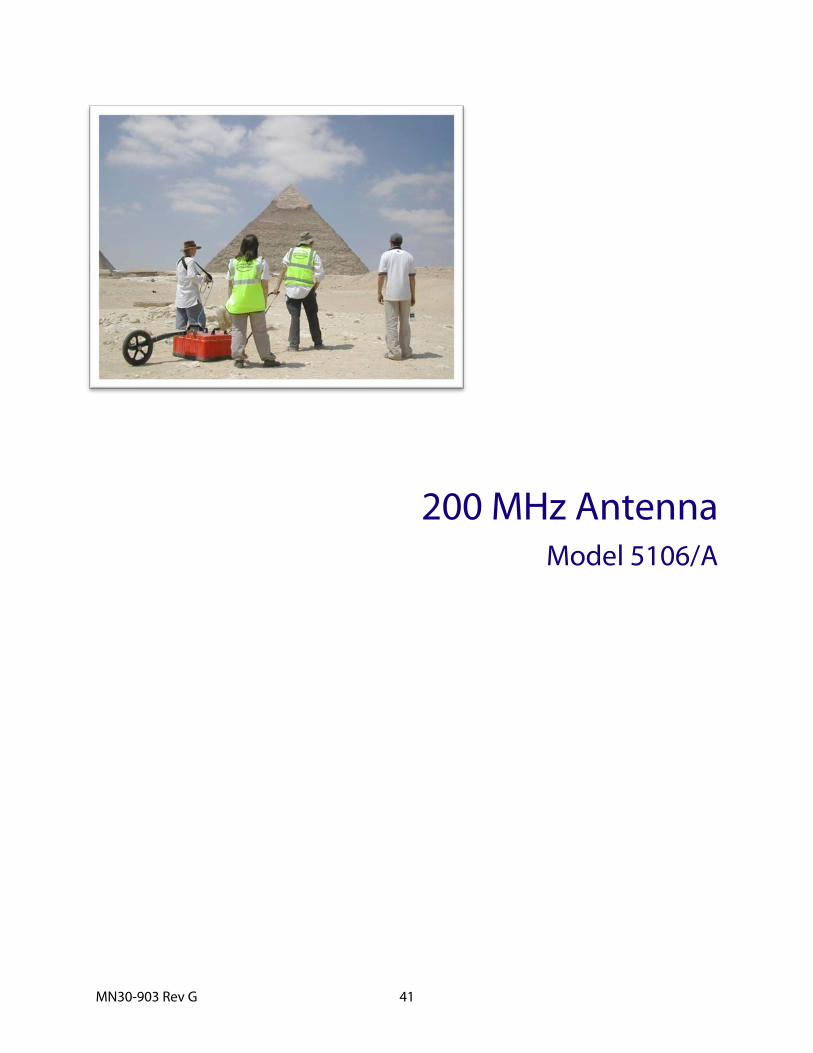
200 MHz Antenna Model 5106/A

MN30-903 Rev G 42

Geophysical Survey Systems, Inc. 200 MHz Antenna Model 5106/5106A
MN30-903 Rev G 43
200 MHz Antenna The Model 5106/A antenna has greatly improved resolution performance over previous GSSI mid-frequency antennas, such as the Model 3105 (300 MHz). The Model 5106/A can be used in continuous, survey wheel or static stacking modes.
System Setup - Standard Settings
Shallow Profiling: Range/Depth is approximately 7m assuming a dielectric constant of 9.
Setup Mode: Manual
System Run Mode: Survey Wheel (recommended) or Continuous
Range:150 ns
Number of Gain Points: 5
Vertical Low Pass Filter: 400 MHz
Vertical High Pass Filter: 30 MHz
Samples per Scan: 512
Bits per Sample: 16
Scans per Second: Set to the maximum scan rate allowed by the SIR System used.
Deep Profiling: Range/Depth is approximately 15m assuming a dielectric
Setup Mode: Manual
System Run Mode: Survey Wheel (recommended) or Continuous
Range: 300 ns
Number of Gain Points: 5
Vertical Low Pass Filter: 400 MHz
Vertical High Pass Filter: 30 MHz
Samples per Scan: 1024
Bits per Sample: 16
Scans per Second: Set to the maximum scan rate allowed by the SIR System used.
Geophysical Survey Systems, Inc. 200 MHz Antenna Model 5106/5106A
MN30-903 Rev G 44
Signal Position Place the antenna on the ground and use the Automatic Signal Position selection. The system will servo and place the direct coupling pulse at the top of the time range window.
To test that you have the correct position, raise the antenna off the ground and you will observe on your system that the antenna transmit pulse will separate from the reflection from the ground. The higher that you raise the antenna, the further apart will be the two pulses.
To assure that the direct coupling pulse (time zero) is recorded the user should place the signal Position servo in the manual mode. The signal should then be moved down in the time range window until the entire surface pulse is visible and there is some ‘dead time’ or flat trace visible above the direct coupling pulse in the time range window.
Gain Check The surface pulse should be about 2/3 the width of the screen. If it is greater, reduce the Gains manually. If the signal appears too small you can manually increase the Gains, but the first gain point should never exceed 10dB, the last gain point should not exceed 65dB.
Specifications Center frequency: 200 MHz
Pulse duration: 5 ns
Depth of penetration: 0-30 ft depending on dielectric permittivity
Size of sensor: 12x12x6.5 inches (60x60x30cm)
Weight of sensor: 39 lbs (17.72 kg)
MN30-903 Rev G 45
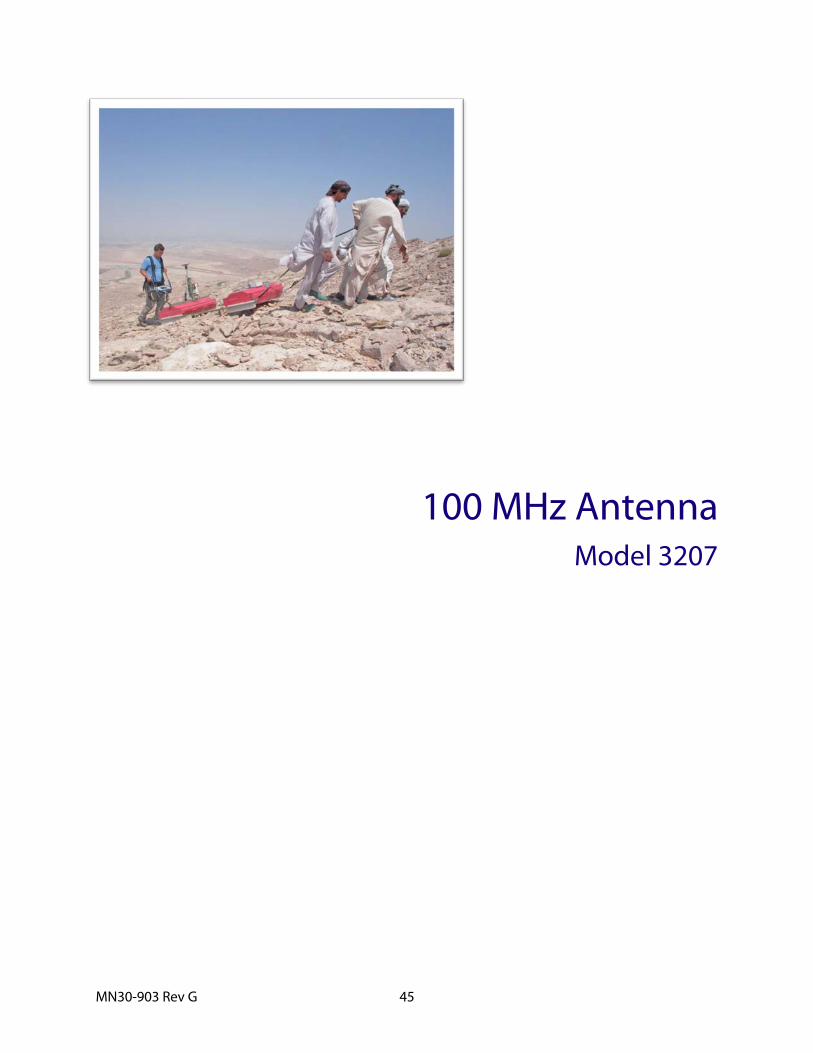
100 MHz Antenna Model 3207

MN30-903 Rev G 46
Geophysical Survey Systems, Inc. 100 MHz Antenna Model 3207
MN30-903 Rev G 47
100 MHz Antenna Thank you for purchasing a Model 3207 antenna. The 3207 represents the state of the art in deeper GPR penetration and resolution. It is ideal for situations which require effective imaging of earth and rock structures at depth.
The 3207 is available in two different configurations. The mono-static configuration is comprised of a single 3207 antenna housing with a Model 769DA2 transceiver electronic plug-in card with the transmit and receive jumpers fed into each other. Since it is only one 3207 housing, the mono-static configuration is an ideal choice for applications requiring a smaller size antenna with deep penetration. This configuration is known as the 3207AP.
The 3207 Pair allows for deeper penetration and for Common Mid Point (CMP) analysis. It is comprised of two 3207 antenna housings linked together by fiberglass rails or kept separate for CMP analysis. One of the housings is a dedicated transmitter and one is a dedicated receiver. The receiver has the Model 769DA2 transceiver electronic plug-in card with a transmitter cable connected to the “Out” port. The transmitter has a Model 778 High-Power transmit electronic card with the transmit cable connected from the 769DA2. The 3207 Pair is designed to be operated with a minimum 1 meter separation between the transmitted and the receiver. Gray fiberglass rails are provided to connect the antennas and keep a constant separation distance. This configuration is known as the 3207P.
Note: A fiber optic transmit link (Model 570) is available to use with the 3207P. The Model 570 is used in place of the coaxial transmitter cable. Use of the Model 570 will result in better performance*. The Model 570 is available as a separate purchase or as part of the Model 3207F configuration.. Contact your GSSI representative or email [email protected] for details.
The Model 3207 has a center frequency of 100 MHz.
GSSI Technical Support is available from Monday to Friday, 8:00 AM to 5:00 PM, Eastern US Time. You can also find help of the internet at https://support.geophysical.com.
* GSSI strongly recommends using the Model 570 when the 3207P (pair) is used with the SIR-3000.
Geophysical Survey Systems, Inc. 100 MHz Antenna Model 3207
MN30-903 Rev G 48
Operating Notes for the 3207P & 3207AP
Understanding the Electronic Plug-In Cards The Model 3207 antenna elements need electronic plug-in cards inserted in order to function. The combination of 3207 elements with the correct plug-in electronic card results in a functional antenna. These cards allow the elements to act as either transmitter, receiver, or transceiver. The cards are referred to by their model numbers. These numbers are printed on the face plate of the card. There are two types of cards available for the antenna elements.
These cards are shipped already inserted into the respective 3207 element. They are pushed into place and secured with two screws on the sides of the faceplate. The cards are removable and GSSI Field Service may direct you to remove them if damage is suspected. If you do remove them, try to avoid touching the internal connectors or the components on the boards.
Note: Never remove any electronic plug-in while the antenna is powered up. Doing so will damage your cards. You should consider the antenna powered whenever the control cable is attached and your SIR System is turned on.
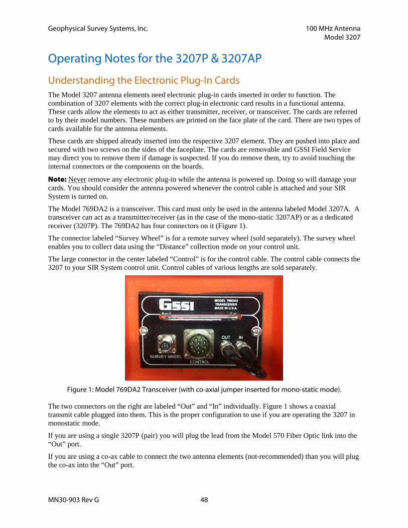
The Model 769DA2 is a transceiver. This card must only be used in the antenna labeled Model 3207A. A transceiver can act as a transmitter/receiver (as in the case of the mono-static 3207AP) or as a dedicated receiver (3207P). The 769DA2 has four connectors on it (Figure 1).
The connector labeled “Survey Wheel” is for a remote survey wheel (sold separately). The survey wheel enables you to collect data using the “Distance” collection mode on your control unit.
The large connector in the center labeled “Control” is for the control cable. The control cable connects the 3207 to your SIR System control unit. Control cables of various lengths are sold separately.
Figure 1: Model 769DA2 Transceiver (with co-axial jumper inserted for mono-static mode).
The two connectors on the right are labeled “Out” and “In” individually. Figure 1 shows a coaxial transmit cable plugged into them. This is the proper configuration to use if you are operating the 3207 in monostatic mode.
If you are using a single 3207P (pair) you will plug the lead from the Model 570 Fiber Optic link into the “Out” port.
If you are using a co-ax cable to connect the two antenna elements (not-recommended) than you will plug the co-ax into the “Out” port.

Geophysical Survey Systems, Inc. 100 MHz Antenna Model 3207
MN30-903 Rev G 49
The Model 778 (Figure 2) is a dedicated transmitter and can only be used as part of a 3207P (pair). This card must only be used in the antenna labeled 3207. It is not used if you are operating a mono-static 3207AP. It has one connector on it, labeled “Xmit”. You will plug one end of a coaxial transmitter cable or Model 570 fiber optic transmit link (recommended) into this connector (Figure 2). You will plug the other end of the cable into the “Out” port on the Model 762DA2 Transceiver.
Figure 2: Model 778 Transmitter.
Operational Modes The 3207 can be operated in three modes:
1. Bi-Static
2. Mono-Static (3207AP with 769DA2 Transceiver)
Bi-Static Mode The Bi-Static mode is configured by separating the 3207 transmitter and 3207 receiver elements by a minimum of three (3) feet with the fiberglass tie bar extensions (Figure 3). The Model 778 transmitter should be plugged into the 3207 element that will lead as you drag the antennas. Plug the Model 769DA2 into the element that will follow. Connect the two electronic cards together with the longer of the two coaxial transmitter cables or with the Model 570 Fiber Optic Link (recommended). Attach the control cable to the Model 769DA2. If your control cable has a stress-relief clip, attach it to the metal eye bolt on the 3207 case.

Geophysical Survey Systems, Inc. 100 MHz Antenna Model 3207
MN30-903 Rev G 50
Figure 3: Hardware Setup for the 3207 Bi-Static using the co-axial transmit trigger cable.
Note: In the bi-static mode of operation, the coaxial cable (transmitter trigger) which must be attached between the two elements must not sag down below the front and back case edges. A trigger cable too low will cause a ringing between the two elements. Use of the Model 570 Fiber Optic Transmit Link will produce better quality data.
Use of the Model 570 Fiber Optic link is STRONGLY recommended for using the antenna in bistatic mode with a SIR-3000.
Mono-Static Mode (3207AP) The Mono-Static mode can be obtained by using the 3207A antenna element with the Model 769DA2 transceiver. The advantages are a small, lighter package with a single transmitter/receiver apex point. The disadvantage is a 24 nanosecond clear time before you can receive data, a function of the 769DA2 transceiver. In order to have the 769DA2 act as a transceiver, you will need to plug the very short coaxial transmitter cable to connect the In and the Out ports on the Model 769DA2 (Figure 4).
Figure 4: Model 769DA2 Setup for Mono-Static Mode.

Geophysical Survey Systems, Inc. 100 MHz Antenna Model 3207
MN30-903 Rev G 51
Hardware Setup
Figure 6: Bi-Static
Figure 7: Completed 3207P Setup.
Optional Mounting of the Model 620 Survey Wheel Use of a Model 620 survey wheel will allow you to easily collect distance-based data with any configuration of 3207 hardware. This section describes the hardware setup of the Model 620 survey wheel (sold separately).
Geophysical Survey Systems, Inc. 100 MHz Antenna Model 3207
MN30-903 Rev G 52
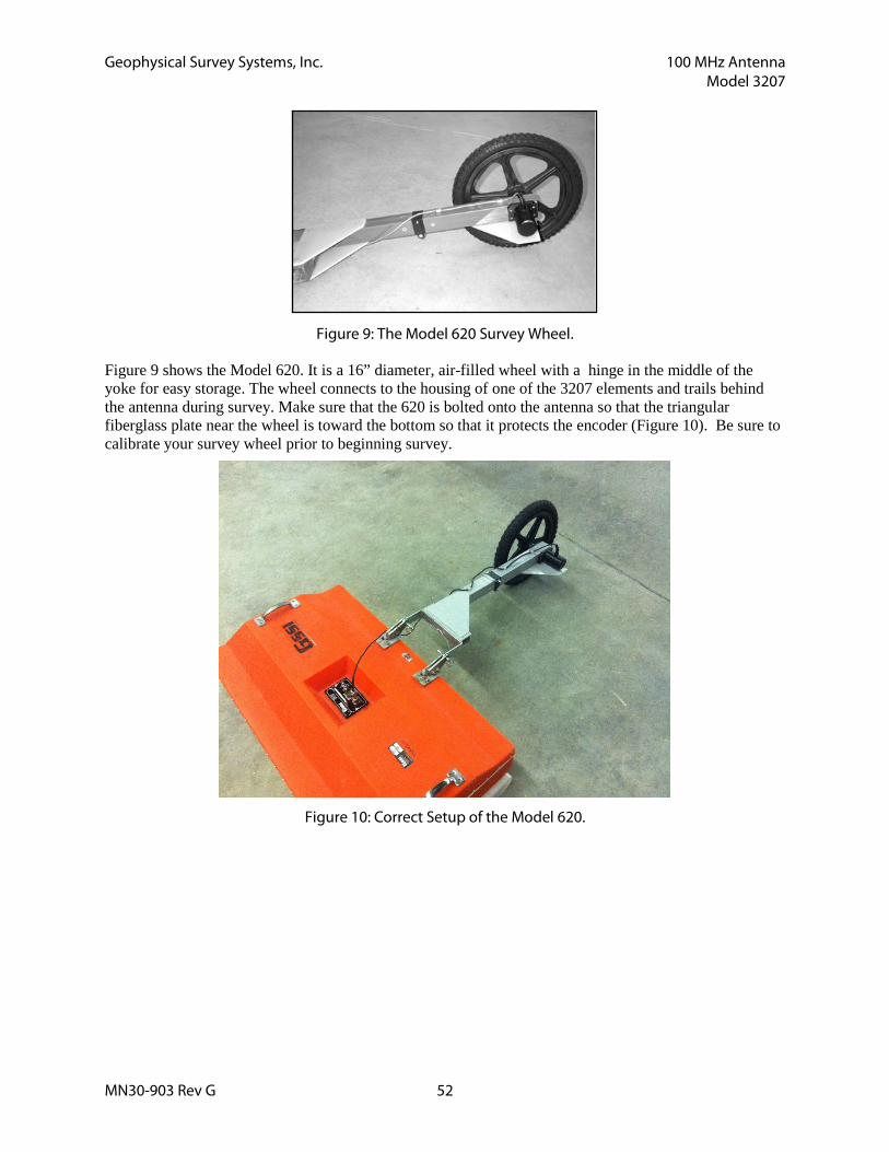
Figure 9: The Model 620 Survey Wheel.
Figure 9 shows the Model 620. It is a 16” diameter, air-filled wheel with a hinge in the middle of the yoke for easy storage. The wheel connects to the housing of one of the 3207 elements and trails behind the antenna during survey. Make sure that the 620 is bolted onto the antenna so that the triangular fiberglass plate near the wheel is toward the bottom so that it protects the encoder (Figure 10). Be sure to calibrate your survey wheel prior to beginning survey.
Figure 10: Correct Setup of the Model 620.
Geophysical Survey Systems, Inc. 100 MHz Antenna Model 3207
MN30-903 Rev G 53
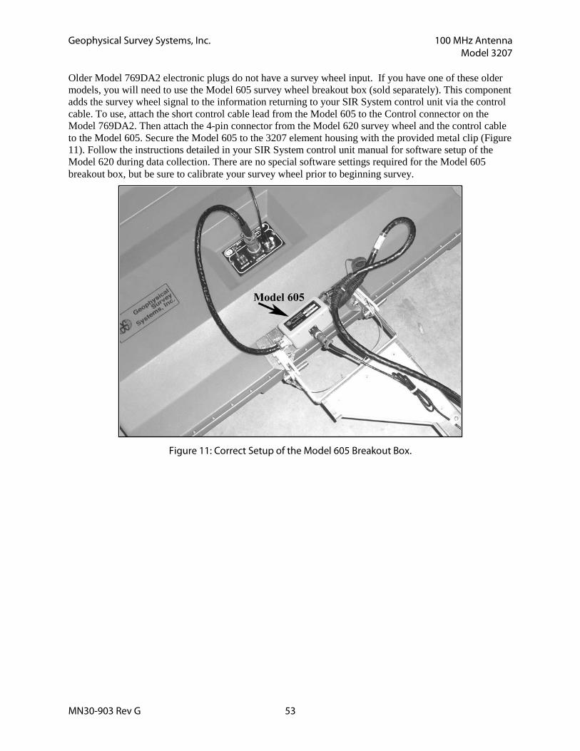
Older Model 769DA2 electronic plugs do not have a survey wheel input. If you have one of these older models, you will need to use the Model 605 survey wheel breakout box (sold separately). This component adds the survey wheel signal to the information returning to your SIR System control unit via the control cable. To use, attach the short control cable lead from the Model 605 to the Control connector on the Model 769DA2. Then attach the 4-pin connector from the Model 620 survey wheel and the control cable to the Model 605. Secure the Model 605 to the 3207 element housing with the provided metal clip (Figure 11). Follow the instructions detailed in your SIR System control unit manual for software setup of the Model 620 during data collection. There are no special software settings required for the Model 605 breakout box, but be sure to calibrate your survey wheel prior to beginning survey.
Figure 11: Correct Setup of the Model 605 Breakout Box.

Geophysical Survey Systems, Inc. 100 MHz Antenna Model 3207
MN30-903 Rev G 54
Software System Setup – Standard Settings Consult your SIR System manual for instructions on setting up your particular control unit for data collection.
Note: If you intend to use the 3207P (Pair) with a SIR-3000, GSSI strongly recommends purchase of a Model 570 Fiber Optic Transmit Link. This component will allow you to collect cleaner data and will allow faster data collection.
3207AP Suggested Settings These settings are used for the single 3207 antenna element configuration.
System Run Mode: Continuous or Survey Wheel
Transmit Rate: 50 KHz
Range: 300 ns
Number of Gain Points: 5
Vertical Low Pass Filter: 300 MHz
Vertical High Pass Filter: 25 MHz
Stacking: 0 scans (set to 32 or 64 if operating in Point collection mode)
Samples per Scan: 512
Bits per Sample: 16
Scans per Second: 16
3207F (Pair with the Fiber Optic link) Suggested Settings These settings are used for the 3207P (Pair) antenna configuration. These settings assume use of the Model 570 Fiber Optic Transmit Link.
System Run Mode: Continuous or Survey Wheel
Transmit Rate: 25 KHz (6 KHz without the Model 570 fiber optic transmit link)
Range: 300+ ns
Number of Gain Points: 5
Vertical Low Pass Filter: 300 MHz
Vertical High Pass Filter: 25 MHz
Stacking: 0 scans (set to 32 or 64 if operating in Point collection mode)
Samples per Scan: 512
Bits per Sample: 16
Scans per Second: 16 (8)

Geophysical Survey Systems, Inc. 100 MHz Antenna Model 3207
MN30-903 Rev G 55
Antenna Specifications Center frequency: 100 MHz
Pulse duration: 10 ns
Size of single 3207 element: 37.5 × 22 × 10.5 inches (95.25 × 55.75 × 26.5 cm)
Weight of 3207 AP: 35 lbs. (16 kg)
Weight of 3207 P: 70 lbs. (32 kg).
Survey wheel: Model 620: 127 ticks per foot, 417 ticks per meter.
Calibration of wheel is recommended, values given here are approximate.

Geophysical Survey Systems, Inc. 100 MHz Antenna Model 3207
MN30-903 Rev G 56
Geophysical Survey Systems, Inc. 16-80 MHz Antenna Model 3200 MLF
MN30-903 Rev G 57
16-80 MHz Antenna Model 3200 MLF

Geophysical Survey Systems, Inc. 16-80 MHz Antenna Model 3200 MLF
MN30-903 Rev G 58
Geophysical Survey Systems, Inc. 16-80 MHz Antenna Model 3200 MLF
MN30-903 Rev G 59
16-80 MHz Antenna
Introduction Thank you for purchasing a Model 3200 MLF Multiple (Adjustable) Low-Frequency Antenna. This antenna is designed for applications requiring deep penetration and variable transmitter/ receiver geometry capability. The unique design allows the user to adjust the transmission frequency of the antenna. This feature gives the SIR System user greater flexibility when site or project conditions and requirements change. In addition, the variable transmitter/receiver geometry capability of the 3200 MLF enables the user to conduct Wide Angle Reflection and Refraction (WARR), Common Mid-Point (CMP) and trans-illumination investigations.
Please read through this manual before setting up and operating the antenna.
Major Features • Environmentally sealed receiver and transmitter electronics
• Transmission frequency adjustable from 80 to 16 MHz (ground-coupled)
• Integral fiber-optic transmit trigger for reduced noise
• Light weight
• Operates in continuous or static (point collection) mode
• Adjustable carrying handle
Check your package with the packing list upon receipt of order.
Please check the packing list included with your shipment that lists all of the parts for the Model 3200 MLF. If you find that an item is missing or damaged during shipment, please call or fax your GSSI sales representative.
Items Include: (1) Model 3200 MLF Transmitter (2) 5 m fiber-optic cable
(1) Model 3200 MLF Receiver (2) 12 VDC batteries
(4) 60 cm antenna elements (1) Battery charger
(4) Telescopic 120-240 cm antenna elements
(4) Adjustable antenna supports
(2) Antenna handles
Geophysical Survey Systems, Inc. 16-80 MHz Antenna Model 3200 MLF
MN30-903 Rev G 60
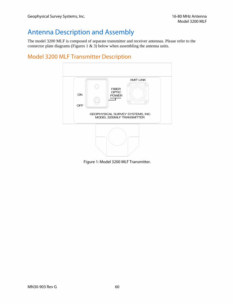
Antenna Description and Assembly The model 3200 MLF is composed of separate transmitter and receiver antennas. Please refer to the connector plate diagrams (Figures 1 & 3) below when assembling the antenna units.
Model 3200 MLF Transmitter Description
Figure 1: Model 3200 MLF Transmitter.
XMIT LINK
GEOPHYSICAL SURVEY SYSTEMS, INC.MODEL 3200MLF TRANSMITTER
ON
OFF
POWER
FIBEROPTIC
Geophysical Survey Systems, Inc. 16-80 MHz Antenna Model 3200 MLF
MN30-903 Rev G 61
Model 3200 MLF Receiver Description
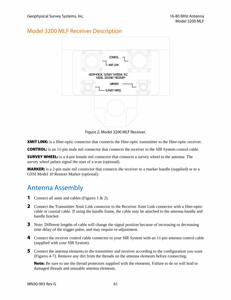
Figure 2: Model 3200 MLF Receiver.
XMIT LINK: is a fiber-optic connector that connects the fiber-optic transmitter to the fiber-optic receiver.
CONTROL: is an 11-pin male mil connector that connects the receiver to the SIR System control cable.
SURVEY WHEEL: is a 4-pin female mil connector that connects a survey wheel to the antenna. The survey wheel pulses signal the start of a scan (optional).
MARKER: is a 2-pin male mil connector that connects the receiver to a marker handle (supplied) or to a GSSI Model 10 Remote Marker (optional).
Antenna Assembly 1 Connect all units and cables (Figures 1 & 2).
2 Connect the Transmitter Xmit Link connector to the Receiver Xmit Link connector with a fiber-optic cable or coaxial cable. If using the handle frame, the cable may be attached to the antenna handle and handle bracket.
3 Note: Different lengths of cable will change the signal position because of increasing or decreasing time delay of the trigger pulse, and may require re-adjustment.
4 Connect the receiver control cable connector to your SIR System with an 11-pin antenna control cable (supplied with your SIR System).
5 Connect the antenna elements to the transmitter and receiver according to the configuration you want (Figures 4-7). Remove any dirt from the threads on the antenna elements before connecting.
Note: Be sure to use the thread protectors supplied with the elements. Failure to do so will lead to damaged threads and unusable antenna elements.
SURVEY WHEEL
CONTROL
XMIT LINK
MODEL 3200MLF RECEIVERGEOPHYSICAL SURVEY SYSTEMS, INC.
MARKER
Geophysical Survey Systems, Inc. 16-80 MHz Antenna Model 3200 MLF
MN30-903 Rev G 62
6 Connect the receiver marker connector to a GSSI Model 10 Remote Marker (optional feature).
7 Connect the receiver survey wheel connector to a GSSI Survey Wheel (optional feature).
• The handle bracket connects the two antenna bracket supports for operation of the Model 3200 MLF in a fixed offset mode for continuous or static-stacked profiles.
• The adjustable antenna supports are for use with the 40 MHz, 20 and 16 MHz antennas. The supports connect between the antenna handle and antenna elements for the longer antenna lengths.
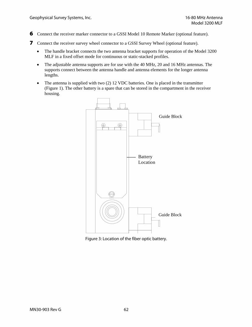
• The antenna is supplied with two (2) 12 VDC batteries. One is placed in the transmitter (Figure 1). The other battery is a spare that can be stored in the compartment in the receiver housing.
BatteryLocation
Figure 3: Location of the fiber optic battery.
Guide Block
Guide Block
Geophysical Survey Systems, Inc. 16-80 MHz Antenna Model 3200 MLF
MN30-903 Rev G 63
Antenna Set-Up Procedure
Center Frequency Adjustment As the lengths of the antenna elements are increased, the antenna frequency decreases and the depth of penetration increases. The following sections describe how to assemble the antenna for various frequencies.
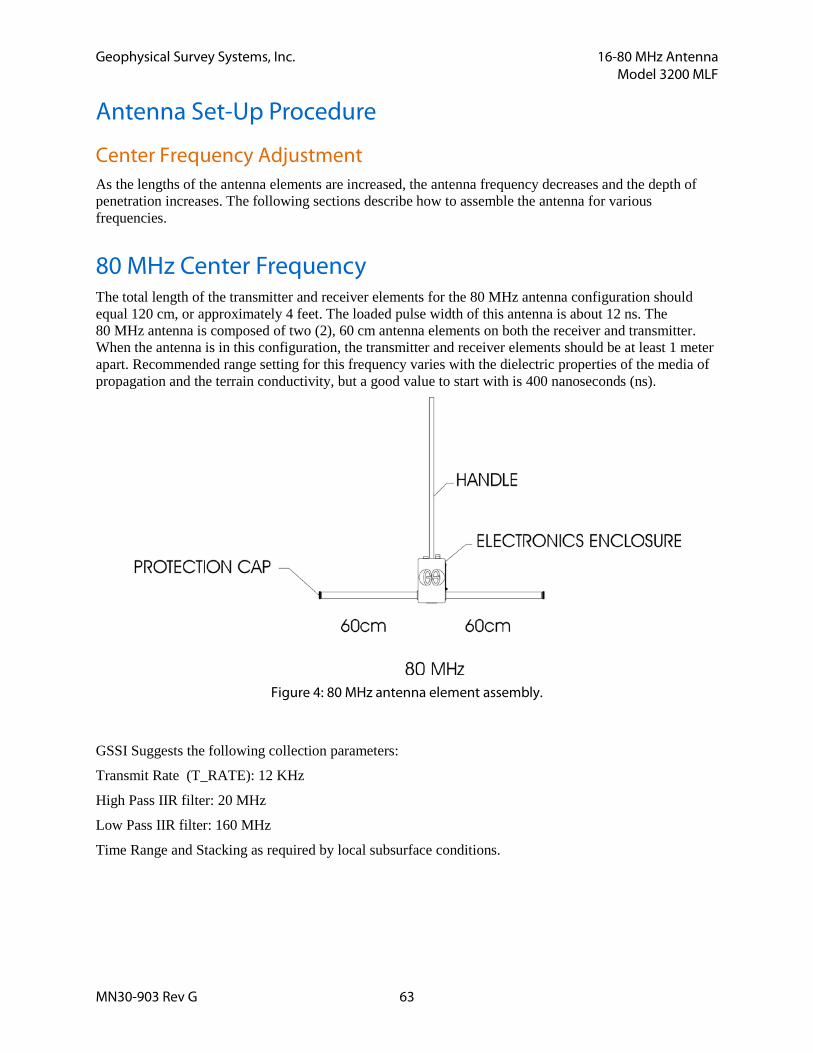
80 MHz Center Frequency The total length of the transmitter and receiver elements for the 80 MHz antenna configuration should equal 120 cm, or approximately 4 feet. The loaded pulse width of this antenna is about 12 ns. The 80 MHz antenna is composed of two (2), 60 cm antenna elements on both the receiver and transmitter. When the antenna is in this configuration, the transmitter and receiver elements should be at least 1 meter apart. Recommended range setting for this frequency varies with the dielectric properties of the media of propagation and the terrain conductivity, but a good value to start with is 400 nanoseconds (ns).
Figure 4: 80 MHz antenna element assembly.
GSSI Suggests the following collection parameters:
Transmit Rate (T_RATE): 12 KHz
High Pass IIR filter: 20 MHz
Low Pass IIR filter: 160 MHz
Time Range and Stacking as required by local subsurface conditions.

Geophysical Survey Systems, Inc. 16-80 MHz Antenna Model 3200 MLF
MN30-903 Rev G 64
40 MHz Center Frequency The total length of the transmitter and receiver elements for a 40 MHz antenna should equal 240 cm, or approximately 8 feet. The loaded pulse width of this antenna is approximately 25 ns. The 40 MHz antenna is composed of two (2) fully retracted (120 cm) telescopic antenna elements on both the receiver and transmitter. When the antenna is in this configuration, the transmitter and receiver elements should be at least 2 meters apart. Again, the range setting for any given frequency varies with the terrain conductivity and dielectric properties, but a good initial setting for this configuration is 800 ns.
Figure 5: 40 MHz antenna element assembly.
GSSI Suggests the following collection parameters:
Transmit Rate (T_RATE): 12 KHz
High Pass IIR filter: 10 MHz
Low Pass IIR filter: 80 MHz
Time Range and Stacking as required by local subsurface conditions.
Geophysical Survey Systems, Inc. 16-80 MHz Antenna Model 3200 MLF
MN30-903 Rev G 65
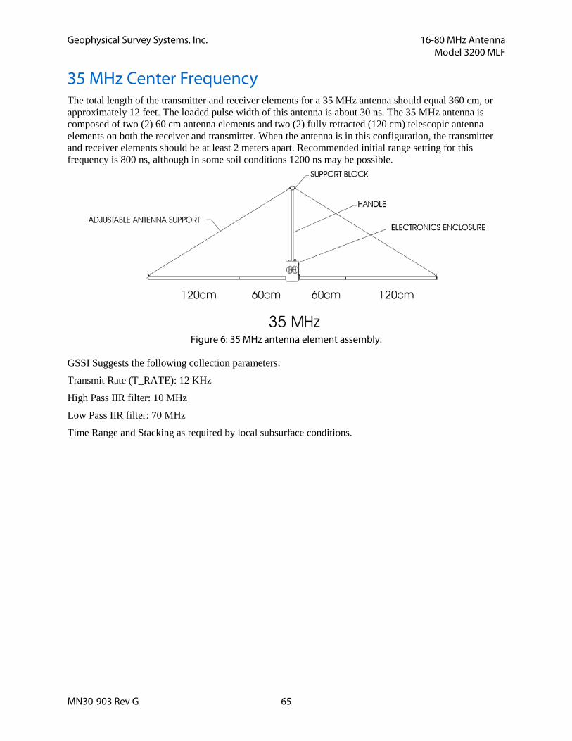
35 MHz Center Frequency The total length of the transmitter and receiver elements for a 35 MHz antenna should equal 360 cm, or approximately 12 feet. The loaded pulse width of this antenna is about 30 ns. The 35 MHz antenna is composed of two (2) 60 cm antenna elements and two (2) fully retracted (120 cm) telescopic antenna elements on both the receiver and transmitter. When the antenna is in this configuration, the transmitter and receiver elements should be at least 2 meters apart. Recommended initial range setting for this frequency is 800 ns, although in some soil conditions 1200 ns may be possible.
Figure 6: 35 MHz antenna element assembly.
GSSI Suggests the following collection parameters:
Transmit Rate (T_RATE): 12 KHz
High Pass IIR filter: 10 MHz
Low Pass IIR filter: 70 MHz
Time Range and Stacking as required by local subsurface conditions.
Geophysical Survey Systems, Inc. 16-80 MHz Antenna Model 3200 MLF
MN30-903 Rev G 66
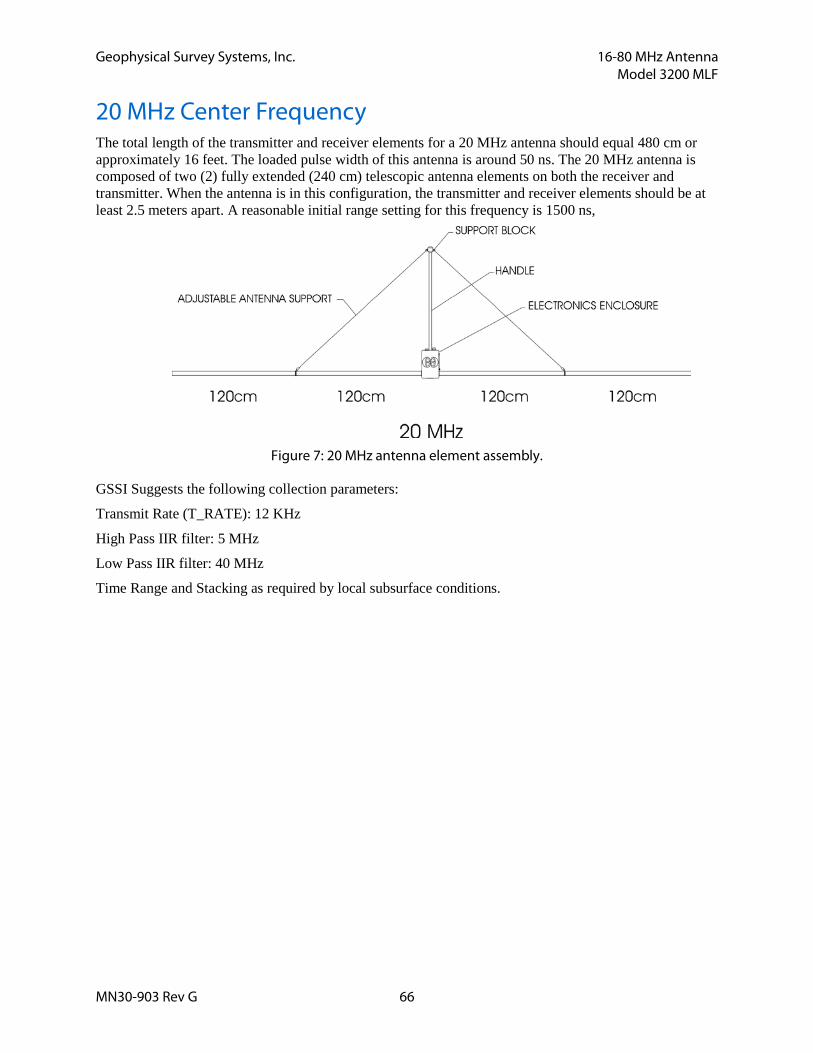
20 MHz Center Frequency The total length of the transmitter and receiver elements for a 20 MHz antenna should equal 480 cm or approximately 16 feet. The loaded pulse width of this antenna is around 50 ns. The 20 MHz antenna is composed of two (2) fully extended (240 cm) telescopic antenna elements on both the receiver and transmitter. When the antenna is in this configuration, the transmitter and receiver elements should be at least 2.5 meters apart. A reasonable initial range setting for this frequency is 1500 ns,
Figure 7: 20 MHz antenna element assembly.
GSSI Suggests the following collection parameters:
Transmit Rate (T_RATE): 12 KHz
High Pass IIR filter: 5 MHz
Low Pass IIR filter: 40 MHz
Time Range and Stacking as required by local subsurface conditions.
Geophysical Survey Systems, Inc. 16-80 MHz Antenna Model 3200 MLF
MN30-903 Rev G 67
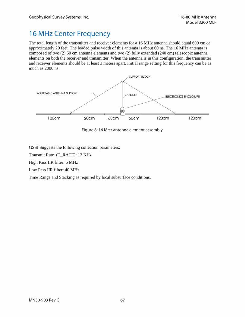
16 MHz Center Frequency The total length of the transmitter and receiver elements for a 16 MHz antenna should equal 600 cm or approximately 20 feet. The loaded pulse width of this antenna is about 60 ns. The 16 MHz antenna is composed of two (2) 60 cm antenna elements and two (2) fully extended (240 cm) telescopic antenna elements on both the receiver and transmitter. When the antenna is in this configuration, the transmitter and receiver elements should be at least 3 meters apart. Initial range setting for this frequency can be as much as 2000 ns.
Figure 8: 16 MHz antenna element assembly.
GSSI Suggests the following collection parameters:
Transmit Rate (T_RATE): 12 KHz
High Pass IIR filter: 5 MHz
Low Pass IIR filter: 40 MHz
Time Range and Stacking as required by local subsurface conditions.

Geophysical Survey Systems, Inc. 16-80 MHz Antenna Model 3200 MLF
MN30-903 Rev G 68
Modes Of Operation The modular design of the 3200 MLF allows the operator to adjust the transmission frequency of the antenna. By the addition or removal of specific antenna elements, the user can alter the center frequency of the transmitter and receiver and thereby adjust both the penetration and resolution capabilities of the radar system.
The Model 3200 MLF can be operated in the following configurations:
1. Bistatic, Fixed T/R offset in Continuous Mode
2. Bistatic, Fixed T/R offset in Static Stacking (point collection) Mode
3. Common Mid-Point in Static Stacking Mode 4. Wide Angle Reflection and Refraction (WARR) in Continuous or Static Stacking Mode
The following sections describe how to use the antenna in each of the above configurations.
Note: Always bear in mind that the Model 3200 MLF is an unshielded antenna. Due consideration must be given to the potential for spurious reflections in the radar data due to proximity of natural or man-made artifacts at or above ground level which, depending upon their proximity to the antennas, may fall within the selected time range window. These spurious reflections may overlap or obscure true subsurface reflectors and serious interpretation errors may arise if care is not exercised during the survey planning and operation stages.
Bistatic, Fixed T/R Offset In Continuous Mode If the terrain permits, this method allows the operator to collect continuous radar profiles. The transmitting and receiving antennas are set up at the appropriate lengths and separations for the frequency chosen, and the antennas are moved simultaneously over an area of interest while the SIR System is scanning. It is desirable for the antenna assemblies to be held in place by resting on a wooden framework (constructed by the user) while being towed over the ground to prevent misalignment and to ensure stability.
Bistatic, Fixed T/R Offset In Static Stacking Mode Where conditions are such that the terrain is not clear enough to do continuous scans with the lower frequency configurations, or a better signal-to-noise ratio is desired, the static stacking mode may be the method of choice. The antennas are set up the same way as for continuous profiling mode, but instead of continuously acquiring data while the antenna is moved along a survey line, the system is operated in point-collection mode. The antennas are placed at a survey point on an established grid, and scans are collected and stacked until the optimum signal-to-noise ratio is achieved and the data is of good quality. The antennas are then moved to the next survey point and the scans are again stacked until a good quality record is acquired. Data collection proceeds in this manner until enough points are stacked to construct a profile over the area of interest.
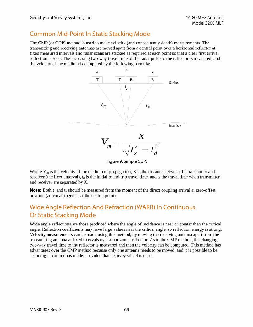
Geophysical Survey Systems, Inc. 16-80 MHz Antenna Model 3200 MLF
MN30-903 Rev G 69
Common Mid-Point In Static Stacking Mode The CMP (or CDP) method is used to make velocity (and consequently depth) measurements. The transmitting and receiving antennas are moved apart from a central point over a horizontal reflector at fixed measured intervals and radar scans are stacked as required at each point so that a clear first arrival reflection is seen. The increasing two-way travel time of the radar pulse to the reflector is measured, and the velocity of the medium is computed by the following formula:
V xt tm
x d= −2 2
Figure 9: Simple CDP.
Where Vm is the velocity of the medium of propagation, X is the distance between the transmitter and receiver (the fixed interval), td is the initial round-trip travel time, and tx the travel time when transmitter and receiver are separated by X.
Note: Both td and tx should be measured from the moment of the direct coupling arrival at zero-offset position (antennas together at the central point).
Wide Angle Reflection And Refraction (WARR) In Continuous Or Static Stacking Mode Wide angle reflections are those produced where the angle of incidence is near or greater than the critical angle. Reflection coefficients may have large values near the critical angle, so reflection energy is strong. Velocity measurements can be made using this method, by moving the receiving antenna apart from the transmitting antenna at fixed intervals over a horizontal reflector. As in the CMP method, the changing two-way travel time to the reflector is measured and then the velocity can be computed. This method has advantages over the CMP method because only one antenna needs to be moved, and it is possible to be scanning in continuous mode, provided that a survey wheel is used.
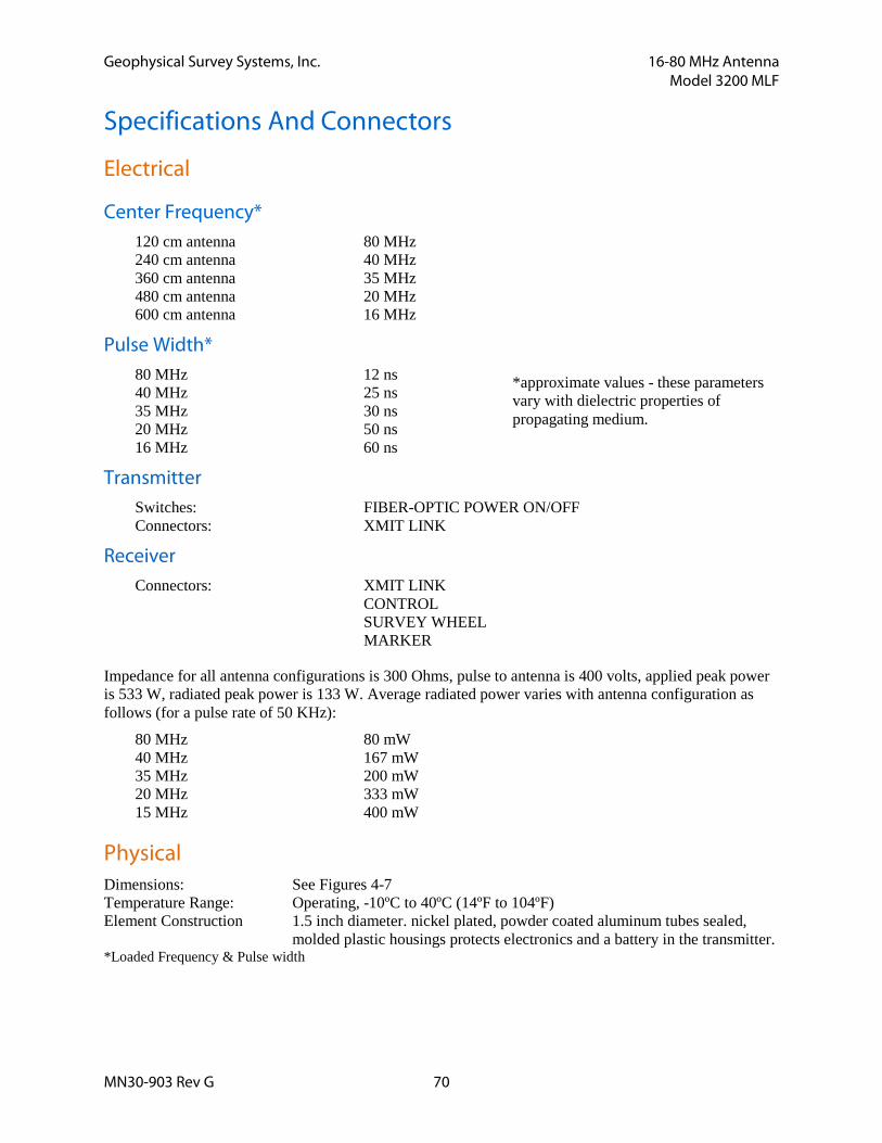
Geophysical Survey Systems, Inc. 16-80 MHz Antenna Model 3200 MLF
MN30-903 Rev G 70
Specifications And Connectors
Electrical
Center Frequency* 120 cm antenna 80 MHz 240 cm antenna 40 MHz 360 cm antenna 35 MHz 480 cm antenna 20 MHz 600 cm antenna 16 MHz
Pulse Width* 80 MHz 12 ns 40 MHz 25 ns 35 MHz 30 ns 20 MHz 50 ns 16 MHz 60 ns
Transmitter Switches: FIBER-OPTIC POWER ON/OFF Connectors: XMIT LINK
Receiver Connectors: XMIT LINK CONTROL SURVEY WHEEL MARKER
Impedance for all antenna configurations is 300 Ohms, pulse to antenna is 400 volts, applied peak power is 533 W, radiated peak power is 133 W. Average radiated power varies with antenna configuration as follows (for a pulse rate of 50 KHz):
80 MHz 80 mW 40 MHz 167 mW 35 MHz 200 mW 20 MHz 333 mW 15 MHz 400 mW
Physical Dimensions: See Figures 4-7 Temperature Range: Operating, -10ºC to 40ºC (14ºF to 104ºF) Element Construction 1.5 inch diameter. nickel plated, powder coated aluminum tubes sealed,
molded plastic housings protects electronics and a battery in the transmitter. *Loaded Frequency & Pulse width
*approximate values - these parameters vary with dielectric properties of propagating medium.
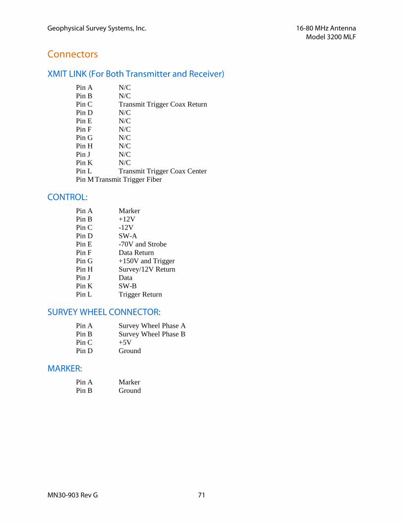
Geophysical Survey Systems, Inc. 16-80 MHz Antenna Model 3200 MLF
MN30-903 Rev G 71
Connectors
XMIT LINK (For Both Transmitter and Receiver) Pin A N/C Pin B N/C Pin C Transmit Trigger Coax Return Pin D N/C Pin E N/C Pin F N/C Pin G N/C Pin H N/C Pin J N/C Pin K N/C Pin L Transmit Trigger Coax Center Pin M Transmit Trigger Fiber
CONTROL: Pin A Marker Pin B +12V Pin C -12V Pin D SW-A Pin E -70V and Strobe Pin F Data Return Pin G +150V and Trigger Pin H Survey/12V Return Pin J Data Pin K SW-B Pin L Trigger Return
SURVEY WHEEL CONNECTOR: Pin A Survey Wheel Phase A Pin B Survey Wheel Phase B Pin C +5V Pin D Ground
MARKER: Pin A Marker Pin B Ground

Geophysical Survey Systems, Inc. 16-80 MHz Antenna Model 3200 MLF
MN30-903 Rev G 72
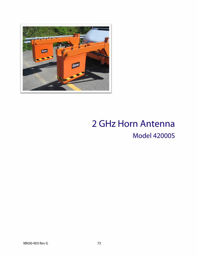
MN30-903 Rev G 73
2 GHz Horn Antenna Model 42000S

MN30-903 Rev G 74

Geophysical Survey Systems, Inc. 2 GHz Horn Antenna Model 42000S
MN30-903 Rev G 75
2 GHz Horn Antenna
Introduction Thank you for purchasing a Model 42000S High Frequency Air Launched Antenna. The 42000S represents the state of the art in high-speed, high-resolution pavement thickness and bridge deck analysis ground penetrating equipment. This antenna is designed for applications requiring very high resolution survey from a moving vehicle. The unique air-launched design allows you to survey at high speeds without causing damage and wear to the antenna. Furthermore, it allows GSSI’s RADAN post-processing software to separate the direct-coupling reflection from the pavement surface reflection. This allows a very accurate measure of pavement thickness.
The 42000S has a center frequency of 2.0 GHz in air.
Note that the 42000S should only be used with the SIR-20 or SIR-30 control unit.
Please read through this manual, as well as the manual for the control unit you are using, thoroughly before attempting to set up and collect data.
If you experience operation problems with your system, GSSI Tech Support can be reached 9am-5pm EST, Monday-Friday, at 1-800-524-3011, or at (603) 893-1109 (International).
Important Note on the Operation of the 42000S The 42000S antenna incorporates a custom designed software filter to reject EM interference. That filter is stored on the USB memory drive which was supplied with the antenna. This drive also contains the latest version of RADAN. If your SIR-20 has a version of RADAN earlier than 6.6.1.5, than you will need to update with the version on the drive.
The information on this drive is crucial to the operation of the antenna. Keep this drive in a safe place. Contact GSSI if you lose the drive and need a replacement file.
To properly install the filter software, plug in the USB memory drive to your SIR-20 and follow the installer’s instructions.
The 2 GHz 42000s incorporates a “smart” chip which will identify the antenna to the SIR-30. This chip will allow the SIR-30 to automatically set default settings. If you are using the 42000S with a SIR-20, you will need to manually configure the SIR-20.
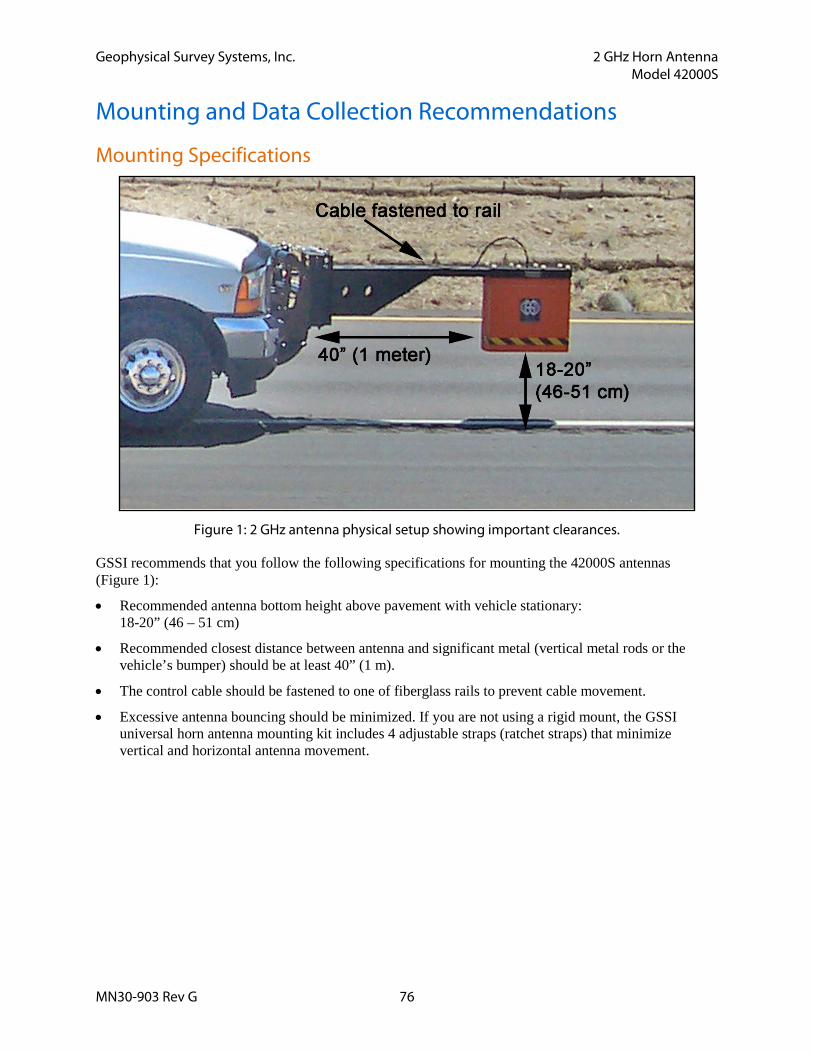
Geophysical Survey Systems, Inc. 2 GHz Horn Antenna Model 42000S
MN30-903 Rev G 76
Mounting and Data Collection Recommendations
Mounting Specifications
Figure 1: 2 GHz antenna physical setup showing important clearances.
GSSI recommends that you follow the following specifications for mounting the 42000S antennas (Figure 1):
• Recommended antenna bottom height above pavement with vehicle stationary: 18-20” (46 – 51 cm)
• Recommended closest distance between antenna and significant metal (vertical metal rods or the vehicle’s bumper) should be at least 40” (1 m).
• The control cable should be fastened to one of fiberglass rails to prevent cable movement.
• Excessive antenna bouncing should be minimized. If you are not using a rigid mount, the GSSI universal horn antenna mounting kit includes 4 adjustable straps (ratchet straps) that minimize vertical and horizontal antenna movement.
Geophysical Survey Systems, Inc. 2 GHz Horn Antenna Model 42000S
MN30-903 Rev G 77
Data Collection Recommendations The following software settings are recommended for general Model 42000S data collection. See the SIR-20 manual for instructions on how to make setting modifications. If you are using a 42000S with the SIR-20, follow the recommended settings below. If you are using a 42000S with a SIR-30, the antenna’s smart module will communicate the proper settings to the SIR-30.
Table 1. Recommended data collection settings for Model 42000S antenna.
SIR-20
Transmit Rate 100-300 KHz †
Samples/Scan 512 Scans/Sec: 100 – 399*
Position Manual – Set the positive peak of direct-coupling should be at least 1.1 ns away from the top of the scan (see Figure 2)
Time Range 12 ns
Gain Auto – 1 Point (use 0.6 auto gain level in Data Collection Project Settings - see SIR-20 manual for details)
Vertical Filter Settings: 100 MHz IIR High Pass
Custom FIR Select filter corresponding to antenna serial number
† FCC regulations require that SIR-20 systems sold in the U.S. are limited to a transmit rate of 100 KHz.
* Use higher scans/sec rate when collecting data at higher scans/m.
Position This point is extremely important. Failure to correctly set the position for data collection will
result in improperly collected data which cannot be processed. Signal position should be adjusted so that the positive peak of the direct-coupling wavelet is at least 1.1 ns from the top of the scan. GSSI’s RADAN post-processing software requires the presence of this wavelet in the data. Figure 2 shows a typical scan of data with the signal properly positioned. The largest amplitude reflection will be the pavement surface. The next largest reflection will be the desired direct-coupling waveform. This will occur several nanoseconds before the pavement surface reflection and appear in the Position window (below) as the next significant waveform to the left of that pavement surface. Unlike ground-coupled
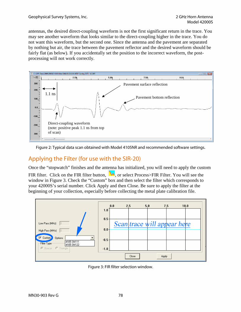
Geophysical Survey Systems, Inc. 2 GHz Horn Antenna Model 42000S
MN30-903 Rev G 78
antennas, the desired direct-coupling waveform is not the first significant return in the trace. You may see another waveform that looks similar to the direct-coupling higher in the trace. You do not want this waveform, but the second one. Since the antenna and the pavement are separated by nothing but air, the trace between the pavement reflector and the desired waveform should be fairly flat (as below). If you accidentally set the position to the incorrect waveform, the post-processing will not work correctly.
Figure 2: Typical data scan obtained with Model 4105NR and recommended software settings.
Applying the Filter (for use with the SIR-20) Once the “stopwatch” finishes and the antenna has initialized, you will need to apply the custom FIR filter. Click on the FIR filter button, , or select Process>FIR Filter. You will see the window in Figure 3. Check the “Custom” box and then select the filter which corresponds to your 42000S’s serial number. Click Apply and then Close. Be sure to apply the filter at the beginning of your collection, especially before collecting the metal plate calibration file.
Figure 3: FIR filter selection window.
Direct-coupling waveform (note: positive peak 1.1 ns from top of scan)
Pavement surface reflection
1.1 ns Pavement bottom reflection
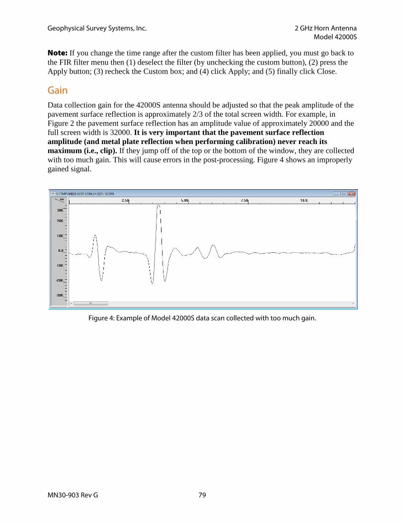
Geophysical Survey Systems, Inc. 2 GHz Horn Antenna Model 42000S
MN30-903 Rev G 79
Note: If you change the time range after the custom filter has been applied, you must go back to the FIR filter menu then (1) deselect the filter (by unchecking the custom button), (2) press the Apply button; (3) recheck the Custom box; and (4) click Apply; and (5) finally click Close.
Gain Data collection gain for the 42000S antenna should be adjusted so that the peak amplitude of the pavement surface reflection is approximately 2/3 of the total screen width. For example, in Figure 2 the pavement surface reflection has an amplitude value of approximately 20000 and the full screen width is 32000. It is very important that the pavement surface reflection amplitude (and metal plate reflection when performing calibration) never reach its maximum (i.e., clip). If they jump off of the top or the bottom of the window, they are collected with too much gain. This will cause errors in the post-processing. Figure 4 shows an improperly gained signal.
Figure 4: Example of Model 42000S data scan collected with too much gain.

Geophysical Survey Systems, Inc. 2 GHz Horn Antenna Model 42000S
MN30-903 Rev G 80
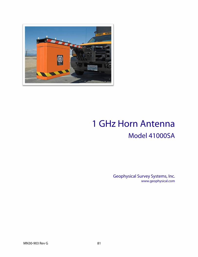
MN30-903 Rev G 81
1 GHz Horn Antenna Model 41000SA
Geophysical Survey Systems, Inc. www.geophysical.com

MN30-903 Rev G 82
Geophysical Survey Systems, Inc. 1 GHz Horn Antenna Model 41000SA
MN30-903 Rev G 83
1 GHz Horn Antenna
Introduction Thank you for purchasing a Model 41000SA High Frequency Air Launched Antenna. The 41000SA represents the state of the art in high-speed, high-resolution pavement thickness and bridge deck analysis ground penetrating equipment. This antenna is designed for applications requiring very high resolution survey from a moving vehicle. The unique air-launched design allows you to survey at high speeds without causing damage and wear to the antenna. Furthermore, it allows GSSI’s RADAN post-processing software to separate the direct-coupling reflection from the pavement surface reflection. This allows a very accurate measure of pavement thickness.
The 41000SA has a center frequency of 1.0 GHz in air.
Note that the 41000SA should only be used with the SIR-20 or SIR-30 control unit.
Please read through this manual, as well as the manual for the control unit you are using, thoroughly before attempting to set up and collect data.
If you experience operation problems with your system, GSSI Tech Support can be reached 9am-5pm EST, Monday-Friday, at 1-800-524-3011, or at (603) 893-1109 (International).
Important Note on the Operation of the 41000SA The 41000SA antenna incorporates a custom designed software filter to reject EM interference. That filter is stored on the USB memory drive which was supplied with the antenna. This drive also contains the latest version of RADAN. If your SIR-20 has a version of RADAN earlier than 6.6.1.5, than you will need to update with the version on the drive.
The information on this drive is crucial to the operation of the antenna. Keep this drive in a safe place. Contact GSSI if you lose the drive and need a replacement file.
To properly install the filter software, plug in the USB memory drive to your SIR-20 and follow the installer’s instructions.
The 1 GHz 41000SA incorporates a “smart” chip which will identify the antenna to the SIR-30. This chip will allow the SIR-30 to automatically set default settings. If you are using the 42000S with a SIR-20, you will need to manually configure the SIR-20.
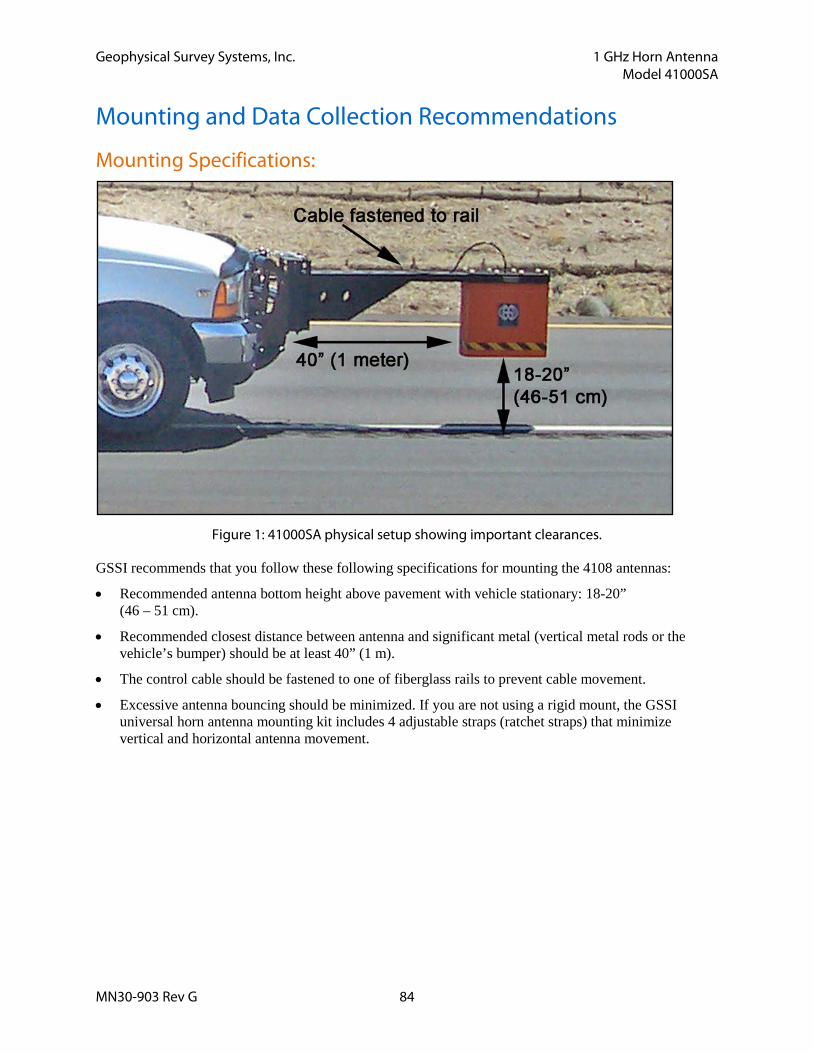
Geophysical Survey Systems, Inc. 1 GHz Horn Antenna Model 41000SA
MN30-903 Rev G 84
Mounting and Data Collection Recommendations
Mounting Specifications:
Figure 1: 41000SA physical setup showing important clearances.
GSSI recommends that you follow these following specifications for mounting the 4108 antennas:
• Recommended antenna bottom height above pavement with vehicle stationary: 18-20” (46 – 51 cm).
• Recommended closest distance between antenna and significant metal (vertical metal rods or the vehicle’s bumper) should be at least 40” (1 m).
• The control cable should be fastened to one of fiberglass rails to prevent cable movement.
• Excessive antenna bouncing should be minimized. If you are not using a rigid mount, the GSSI universal horn antenna mounting kit includes 4 adjustable straps (ratchet straps) that minimize vertical and horizontal antenna movement.
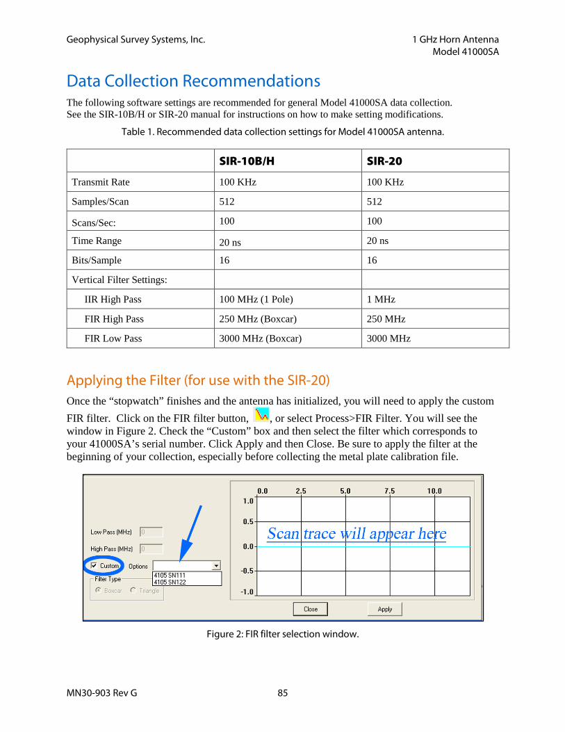
Geophysical Survey Systems, Inc. 1 GHz Horn Antenna Model 41000SA
MN30-903 Rev G 85
Data Collection Recommendations The following software settings are recommended for general Model 41000SA data collection. See the SIR-10B/H or SIR-20 manual for instructions on how to make setting modifications.
Table 1. Recommended data collection settings for Model 41000SA antenna.
SIR-10B/H SIR-20
Transmit Rate 100 KHz 100 KHz
Samples/Scan 512 512
Scans/Sec: 100 100
Time Range 20 ns 20 ns
Bits/Sample 16 16
Vertical Filter Settings:
IIR High Pass 100 MHz (1 Pole) 1 MHz
FIR High Pass 250 MHz (Boxcar) 250 MHz
FIR Low Pass 3000 MHz (Boxcar) 3000 MHz
Applying the Filter (for use with the SIR-20) Once the “stopwatch” finishes and the antenna has initialized, you will need to apply the custom FIR filter. Click on the FIR filter button, , or select Process>FIR Filter. You will see the window in Figure 2. Check the “Custom” box and then select the filter which corresponds to your 41000SA’s serial number. Click Apply and then Close. Be sure to apply the filter at the beginning of your collection, especially before collecting the metal plate calibration file.
Figure 2: FIR filter selection window.
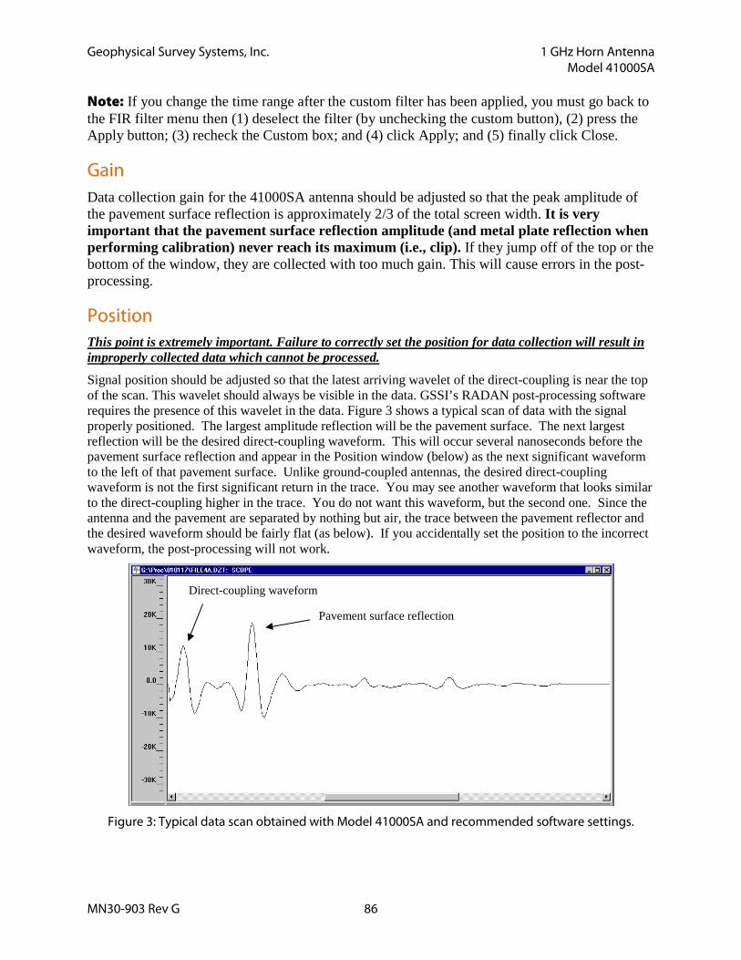
Geophysical Survey Systems, Inc. 1 GHz Horn Antenna Model 41000SA
MN30-903 Rev G 86
Note: If you change the time range after the custom filter has been applied, you must go back to the FIR filter menu then (1) deselect the filter (by unchecking the custom button), (2) press the Apply button; (3) recheck the Custom box; and (4) click Apply; and (5) finally click Close.
Gain Data collection gain for the 41000SA antenna should be adjusted so that the peak amplitude of the pavement surface reflection is approximately 2/3 of the total screen width. It is very important that the pavement surface reflection amplitude (and metal plate reflection when performing calibration) never reach its maximum (i.e., clip). If they jump off of the top or the bottom of the window, they are collected with too much gain. This will cause errors in the post-processing.
Position This point is extremely important. Failure to correctly set the position for data collection will result in improperly collected data which cannot be processed.
Signal position should be adjusted so that the latest arriving wavelet of the direct-coupling is near the top of the scan. This wavelet should always be visible in the data. GSSI’s RADAN post-processing software requires the presence of this wavelet in the data. Figure 3 shows a typical scan of data with the signal properly positioned. The largest amplitude reflection will be the pavement surface. The next largest reflection will be the desired direct-coupling waveform. This will occur several nanoseconds before the pavement surface reflection and appear in the Position window (below) as the next significant waveform to the left of that pavement surface. Unlike ground-coupled antennas, the desired direct-coupling waveform is not the first significant return in the trace. You may see another waveform that looks similar to the direct-coupling higher in the trace. You do not want this waveform, but the second one. Since the antenna and the pavement are separated by nothing but air, the trace between the pavement reflector and the desired waveform should be fairly flat (as below). If you accidentally set the position to the incorrect waveform, the post-processing will not work.
Figure 3: Typical data scan obtained with Model 41000SA and recommended software settings.
Direct-coupling waveform
Pavement surface reflection
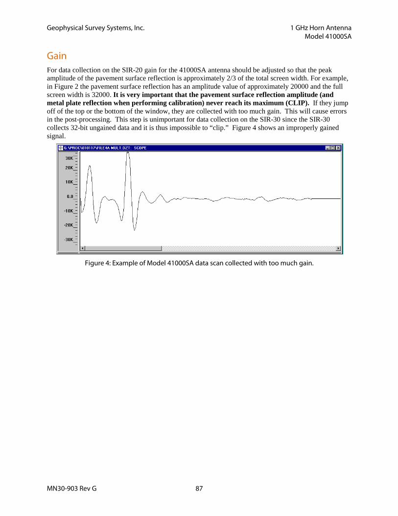
Geophysical Survey Systems, Inc. 1 GHz Horn Antenna Model 41000SA
MN30-903 Rev G 87
Gain For data collection on the SIR-20 gain for the 41000SA antenna should be adjusted so that the peak amplitude of the pavement surface reflection is approximately 2/3 of the total screen width. For example, in Figure 2 the pavement surface reflection has an amplitude value of approximately 20000 and the full screen width is 32000. It is very important that the pavement surface reflection amplitude (and metal plate reflection when performing calibration) never reach its maximum (CLIP). If they jump off of the top or the bottom of the window, they are collected with too much gain. This will cause errors in the post-processing. This step is unimportant for data collection on the SIR-30 since the SIR-30 collects 32-bit ungained data and it is thus impossible to “clip.” Figure 4 shows an improperly gained signal.
Figure 4: Example of Model 41000SA data scan collected with too much gain.