george c. marshall space flight center · had been madz using swage tooling that was worn and/or...
TRANSCRIPT

R (MASA -TH-82429) AN INVESTIGATION OF N81-J1402ASSEBBLY AND FERY02HANCE OF A ELSISTOFLEXDINATOBE 1/4 INCH FITTING (NASA) 28 pHC A03/!!F A01 CSCL 13K unclas
G3/31 27434NASA TECHNICAL
MEMORANDUM
NASA TM-82429i
ASSEMBLY AND TESTING OF 114 INCH MR54040 TF04RESI STOFLEX DYNATUBE FITTINGS
By J. H. EhlMaterials and Processes Laboratory
4 K^
June 1981°
M RE^E1F E
,^, ► '^1 off`
NASA
George C. Marshall Space Flight Centerki Marshall Space Flight Center, Alabama
MSFC - F a m :. b (Rev June 1971)
https://ntrs.nasa.gov/search.jsp?R=19810022859 2018-08-03T22:46:53+00:00Z

Trnuu^e-^^ ernner QTA ►Ir%A=r% TIT/ r eAnr1. REPORT NO.
NASA TM-824292. GOVERNMENT ACCESSION NO. S. RECIPIENT'S CATALOG NO.
4. TITLE AND SUBTITLEAn Investigation of Assembly and Performance of A
S. REPORT DATEJune 1981
Resistoflex Dynatube I inch Fitting 6. PERFORMING ORGANIZATION CCCIE
EH 447. AUTNOR(S) O.PERFORMING ORGANIZATION REPORt N
J. H. Ehl9. PERFORMING ORGANIZATION NAME AND ADDRESS 10. WORK UNIT NO.
George C. Marshall Space Flight Center11. CONTRACT OR GRAr ' No.Marshall Space Flight Center, Alabama 35812IS. TYPE Of REPORT Q PERIOD COVERED
Technical Memorandum12. SPONSORING AGENCY NAME AND ADDRESS
National Aeronautics and Space AdministrationWashington, D.C. 30546 14. SPONSORING AGENCY CODE
13. SUPPLEMENTARY NOTES
Prepared by the Materials and Processes Laboratory, Science and EngineeringDirectorate
10. ABSTRACT
Installation of Resistoflex dynatube fittings on I in. tubing is sensitive toworkmanship and to the state of repair of the installation tooling. Tooling withvery slight out-of-specification imperfections will produce less than optimum swagedfittings. This investigation included fabrication of a significant quantity of samples,X-rays to determine the depth of swage and static and dynamic testing to determinejoint performance.
17. KEY WORDS 18. DISTRIBUTION STATEMENT
} in. ResistoflexDynatube Fitting Unclassified-Unlimited
19. SECURITY CLASSIF. (of this reportl 20. SECURITY CLASSIF. (of this pap) 21. NO. OF PAGES 22. PRICE
Unclassified Unclassified 28 NTLSmar v • r orm a 39 a tn". useemou i s -I a) For nk by National Technical Information Senrleo. Bptia sId, Virginia 21161

f
TABLE OF CONTENTS
Page
OF INTRODUCTION AND BACKGROUND .............................. 1
FINDINGS ........................................................ 8
APPENDIX....................................................... 10
iii

LIST OF ILLUSTRATIONS
Figure Title Page
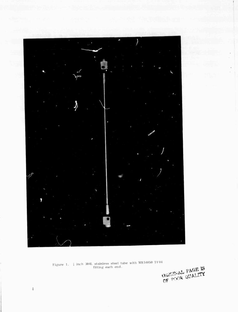
1. } inch 304L stainless steel tube with MR 54040 TF04fitting each end ....................................... 4
2. MR 54040 TF04 dynatube fitting ........................ 5
3. Swage tool (fully assembled) ........................... 6
4. Swage tool (disassembled) ............................. 7
5. Enlarged x-ray of fitting and tube showing minimalswage of tube into fitting grooves ..................... 8
6. Example of possible rotation ........................... 8
7. Set-up for vibration testing ........................... 12
LIST OF TABLES
Table Title Page
1. Vibration Input to SRB TVC Tube (0.25" Dia.)Assemblies ............................................ 13
2. Resistof!ex Dynatube MSrC Testing .................... 15

ACKNOWLEDGMENTS
This investigation was performed with the assistance of:
Walter W. JacksonElbert MinterLeo HeinWendel DeWeeseEdward BallAlex D'AgostinoPhilip TaylorToney BridpesJoe Kins isJames C.L^;:,ounBobby ErwinClifton Kirby
nilEH44EP 33EH22ET44EP42USBI HuntsvilleSK-(SALUSBI M-BACSK -SRB -EED-23ET-18
v

TECHNICAL MEMORANDUM
ASSEMBLY AND PERRWMANCE OF1141 KICH MR54040 TFO4 RES I STOFLEX
DYNATUBE FITTINGS
1. INTRODUCTION AND BACKGROUND
Dynatube is a trade name for a titanium (GAI-W) threaded fittingused to join metal tubing (Figs. i and 2). These fitting are manufac-tured by the Resistoflex Corporation of Roseland, N.J. The outsidesurface of the metal tube is mechanically swaged into grooves in theinside surface of the fitting. Swaging is performed either by manual orpower rotation of an expanding mandrel type tool (Figs. 9 and 4).These fittings have a long history of successful use in commercial andmilitary aircraft and aerospace systems with minimum weight and criticalleak rate requirements.
During build-up of hardware for the Space Shuttle Thrust VectorControl (TVC) system, some tube assemblies using Dynatube fittings 5were fabricated that did not pass the prescribed leak test of 1 x 10standard cubic centimeters per second of helium at 400 psig. Leakagewas detected between the fitting and the outside diameter of the tube.These tests were conducted using a helium sniffer and also by using"Leak Tek" solution and noting bubbles of escaping helium gas. It wasdetermined that these same tube assemblies had previously passed theleak test requirements. Fittings are tested repeatedly as build-up ofthe assembly progresses to the next higher level. Sectioning of theleaking joint revealed a very light awage of less than 0.002 in. radialdeformation of the tube into the fitting grooves which are 0.007 in.deep. Further investigation revealed that some lightly swaged fittingshad passed all hydrostatic leak testing but could be made to leak if theywere rotated on the tube during installation (Figs. 5 and 6).
Further investigation determined that Dynatube fitting assemblieshad been madz using swage tooling that was worn and/or misassembled'.The worn tooling swaged light, as little as 0.002 in. deep in the four0.007 in. deep fitting joints. The misassembled swage tool swaged short,i.e. good swages in the first three grooves but little or no swage in thefarthest groove (4th groove) from the point of entry of the mandrelinto the tube to be swaged. Refurbishment of the tooling by replacingthe warn rollers on the expanding mandrel and by correcting the out ofplace spacer washers in the misassembled tool corrected the problem ofswaging good joints. Correctly assembled and refurbished tooling canconsistently swage grooves 0.005 in. deep or more when u3ed by atrained operator. However. x-ray of inplace tubing assemblies revealed

that some joints had been manufactured and installed that were lightlyswaged and that had successfully passed the helium leak tests. A pro-gram was developed to determine the performance of lightly swaged jointsand to duplicate and test joints equal to or worse than those known tobe installed on the flight TVC hardware. This program was comprisedof the following:
1) To be statistically meaningful, 100 each I in. fittings wereprocured and fabricated into 50 each tube assemblies with one fittingat each and (Fig. 1).
2) All swage tooling was refurbished by the Resistoflex Corporationto the correct company specifications.
3) A tolerance study was made on the tubing, the tooling, and thefitting to determine the worst case swage that could be made (Appendix).Swages were made at minimum possible, medium range. and full depth.Additionally, samples were prepared that were fully swaged, but swagedshort. Swage tool settings to accomplish these conditions were 0.219.0.221, 0.223. 0.225, and 0.228 in. The 0.228 in. setting is the normalsetting recommended by Resistoflex Corporation for these fittings. Allsamples were measured (I.D.) x-rayed to determine amount of swage,proof pressure tested at 7000 psi, mass spectrometer leak tested (sniffermethod) at 400 psi with helium, rotated 15 10 in the fitting to simulate acareless fit-up, re-leak checked, and pressure tested. After rotation,approximately 25 percent of the samples did not pass the helium leak.These were assembled into a closed loop arrangement and pressurisedat 400 psi with water. The pressure was maintained for two weeks.None of the swaged fittings that leaked helium, leaked water during thetwo weeks under pressure.
After static testing, the tubes were vibration tested to Shuttleflight level in the radial, tangential, and longitudinal axis (Table 1).While being vibrated, all tubes were pressurized at 400 psi with watercontaining red dye to enhance visibility in case of a leak. Sixty eachfittings, including all the shallow swages and all the short swages, weretested. None leaked water at 400 psi during the vibration tests whichsimulated flight conditions.
2. FINDINGS
1) Resistoflex Dynatube swage tooling in the proper state of repairand used properly will consistently yield adequate swages. ( 0.005 ormore in the first three grooves.)
2) The light and short swage conditions found were caused byworn and improperly assembled tooling respectively.

S) The inhouse MSFC test program demonstrated that a KRUGl4TF04 swage joint with at least 0.0015 in. radial tube defannatim whynot desirable, will pass the required leak rate of not more than 1 x 10soclp helium at 400 paig. Additionally this joint *21 not lank water whmpressurlymd to 400 psi and vibrated to 28.2 grms composite In the radialand tangential axis and 27.0 firms composite in the longitudinal axis.
3 ^A
I i^urc 1. 1 inch 3041. stainIt -tecl tUilrc with NIR54050 'I 04
fitting each end.
1?ti,lr.^iZ^ E^
1' pCi F. L5

SWAGED TUBE
6AL -4V DYNATUSE FITTING
Figure 2. MR54040 TF04 d-matube fitting.
tf
R.

r++
^^ l..

i Eun
J^
'O.r,.g
u;t
4uc.
r
i

.S3OJ) y
u ^A ^7 ^^n
.O
c
b0 .^.C
•• O
G+> A
C
k `~OZ7 ybt bo
3C
cn
Sri
Otti'31NA.L PAGE ISOF POOR QUAf,M'
8
t
i00*1
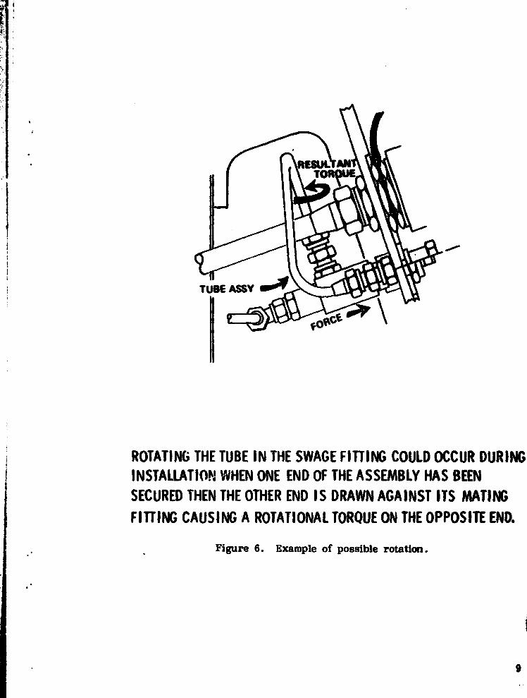
ROTATING THE TUBE IN THE SWAGE FITTING COULD OCCUR DURINGINSTALLATION WHEN ONE END OF THE ASSEMBLY HAS BEENSECURED THEN THE OTHER END IS DRAWN AGAINST ITS MATING
FITTING CAUSING A ROTATIONAL TORQUE ON THE OPPOSITE END.
Figure 6. Example of possible rotation.
8

APPENDIX
10

t .. FITTING
Resistoflex MR 54040
TUBE
MIL-T-68450
TOLERANCE ANALYSIS
Size RangeOutside Diameter
(Inch) Tolerance
} thru } INCL +.004 - .000over } thru 3 +.005 - .000over 11 thru 21 +.010 - .000over 21 thru 3 +.010 - .010over 3 thru 5 +.015 - .015
Tube OD: .250 +.004-.000
Tube Wall: .020 ± .002 = .040 ± .004 cumulative
.250 +•004-.000
-.040 1.004Tube ID = .210 +• 008
-.004
Test GageDiameter .224 ±.002Tube Wt. +.040 ±.004
Range .264 ±.006Fitting ID -.255 ±. 002
.009 ±.008
This tolerance guarantees positive interference fit even if (in the unlikelyevent) the tube is the smallest possible, with the thinnest wall permis-sible, and the fitting is at the extreme upper limit. Factors such asspring back and wall thinning are handled by adding an additional.004 inch extra expansion to tool settings.
i
11
R

W
OdF-.
.j O
$A W
2 goW e3
VW
T•
lefta
2aC00Z
it IT
0v
mMm
ti
.,nW
12

b
TABLE 1. VIBRATION INPUT TO SRB TVC TUBE (0.25" Diu.)ASSEMBLIES
Lift-off and Boost Random Vibration Criteria(180 seconds in each axis)
RADIAL AXIS LONGITUDINAL AXIS
20 Hz 0 0.1 g2 /Hz 20- 60 Hz 0 0.1 C2 /Hz
20- 60 Hz 0 +7 dB /oct 60- 200 Ha 0 +5.5 dB /act
60- 150 Hz @ 1.2 g2/Hz 200- 400 Hz 0 0.9 g2/Hz
150-2000 Hz @ -2 dB /oct 400-2000 Hz 0 - 4 dB /oat
2000 Hz @ 0.2 g2/Hz 2000 Hz @ 0.1 g2/Hz
Composite = 28.2 grms Composite = 27.0 gems
TANGENTIAL AXIS
20- 60 Hz @ 0.1 g2/Hz
60- 100 Hz @ 13.5 dB /oct
100- 300 Hz @ 1.0 g2/Hz
300-2000 Hz @ - 3.5 dB /oct
2000 Hz @ 0.1 g2/Hz
Composite = 28.6 grms
13
r

EXPLANATION OF TABLE 2
The data contained in Table 2 denote the specimen number, thefitting on each end (No. 1 and No. 2) of the tube, the tube diameter ininches, and the swage tool setting in inches. The depth of swage pergroove determination was made by evaluation of x-rays using an opticalcomparator. The No. 1 groove is the first groove from the sealing sur-face and the No. 4 groove is the last groove on the tube end of thefitting. The x-ray is it cross sectional view and the reading is left toright top and bottom. The determination was made by positioning thefine line of the optical comparator on the land of the groove and readingthe amount of upset of the tube into the fittin g ^*roove. The tubeinternal diameter of swage was made using an internal micrometer witha stop to ensure that all tubes were measured at the same position. Thecolumn notinV helium leakage determines if the fitting leaked in excessof 1 x 10 -5 sccs of helium at 100 psi t;. Next, the fitting was rotated15 degrees on the tube to simulate a careless assembly (Fig. 6). Afterrotation the fitting was rechecked with the mass spectrometer to deter-mine leakage. The remaining data column denotes those fittings selectedfor vibration testing;.
14

ML
VzE-+(/J
w
Uw1nz
ww W
C13
H ^Z V
z-. > Z
p xwW H^ VLL
w ^ nN
O ^
VI
z
Nw
FM^1
W
Q
E
r
^iL
.ju0
V
7
W.
CJ
NZ
I
U
0]lS71 x x x x x x x x X x x x x xrn' J" i1.1 _
U i l I Y x% X X % x X(A
$T-
x XXx x x x x x x xl l
I—SM
x
3H x
3J!.S S _^ nn1111/ h y \
eh h h N h h h h
ah
OIh
01
8 ^ 8^ 8 8 ^ 8 ^ 8 8 8 8u 1 8-
0 ^ 8^ 8 8 8 8 8 8 8 8 8 8S
0 8 8 8 8 8 8 8
T t s
Q a S S !S gj =
U -W
o
h 8T 8 8 8N8LL 8. 8 8 8J
08 8 8 8
a
8
a
8
e.
8 3 8 8 8 8 8
-0`011 IS m a m a o m a m N, N,1001 -
h h-
h h hNh N (y
_h h h N h h
30V .'SI
Q 44I
oN No ON
3.1111 ^ ry N M1
Vint
I t ><ia`J111'11 f
."!11111 .. n h h h h n h
iin1 h ^ ♦ a •
15
r

W
NaNH NZW
Was 4c
4cWJV Mt WW H
031531 x x X x x x x x x x x XN01111 tl91 A33'AV31 ON x x x x X x x x x
Veal d S3A x x x
MV3l ON x x x x x x x x x x x xIN S3A
i^Ve^ a n°4 ' '+ x'i a _^
H 31^f N ^^01 rQ1Q'1
[T2
^ °^~ja $ ^ ^
^QQf2S
^Q^
25
^QI
Q
^Q'
25
^Q!
I4
ZS 2{
^Q1
25 8
^fQQI
tiZ
8 8 8 8$ 8^^ 8 8 8 8 8 8nW
1f
aW
J "' ^ 8 ^ 8 ^ 8 ^ ^ 8 8va
^F
$ ^ 8 8 ^ 8 I ^ 8 $ 8 ^ ^ ^ 8 ^ $-<
g
QQE
Q4 QQ2S
Q25
Qi
Q ga 8
Q25
RiS
Q2S $
R2S
O Z
2 VfG a
^ O 8 O O O 8 ^ O ^ O O O O
•
of
WWJ
N ^ 8^ 8^ 8 ^^ ^ ^ 8 ^ 8
a - 8 s" g$ g $ g j s gON1113S
rrM
h M_rr nn ^v n
^^
_
r13JVM5
^/ ry ^I
+^inn
R NR
3nnl
0N1011If
a ONlllli N N N r N r N N N
a )9nl ° O1 0
W
c
OJ
N
wm
F
WQ^
O
wUCbW
cn
b0r-
cod
16
^. r.IL

7C
CCU
Nf
W
u
031531 x x x x x x x x x xhO11VH84A
3 vv 31 ON x x x x x x x x
V1JH ^3A x x x x x x
^V31 ON kx x x x x x x x x x x x x3H S3A
30V.%AS =w = • • ri = S
U311Vry ^ ry h ^^ h ^^
Rh
0I h h M ^1 ^1
Iv
>r
QJ ~v
$ O O v O O O O O O O O
m 8I $ $
o iZ ^CL
o f
W ~
pry {Qy
R ^ ^
(Q^
O
(Qy
V ^ ^Q*G
*QO ^
*QV
J
Q
4
ON1113S " R ,^ " ""^{
a, a1001 ^' ^1 '1 ^ ^^1 ^1 ^~I ^~I ^1 ^I ^I
0033n1
^Q $
^1
g
^I
g
^j R1
g
h36n1 j
^I ^I ^I ^I ^I ^IDrillD
1 U
7 DNI111 f ~ ^ ~ ' N N N h H
37n1 ^' -' = ' R w
:J
VN
:J
L.7
3LC7U.n
17

1
18
J ^ -
- N
2
^ 3n U7
x x x^ x
UJ j! x x x iI x XX x xx _x x
x xj jli[__
x x x x INC x x x x x x_iH ;Sl.\
•ry
8
ry•
~C C
^)C
f i ~kill
01^!
~ hR C
ry_
_C
ry ~
^- ^ I ^ $ O O R ^ ^ ^ ^^ 4 R OJ
^-_^
l f
Z J ~ El
—
^
^
^ 1*QV ^ e*V
(4^
O ^ ^ ^ ^ ^Ii—
S
Q}
" 8 8 $ 8 8 8 8 8 8 8 82 u
J0
0 4111 IS1001
^) N ^i N N N N7ov .^ "1
3Jitl
01 $^I
p+ aI R ^ ^ ^a^1 oI s1 ^j7'Jfll
h n.9.'11l 111 ^ ^^ I ► ti • N - H ^ - h r
it l l ^ I ^i i n 1 ^' ^ r'i ^^-
w
0^N^WV
wc,7
bLC
tn^a
W
HQ V^ ZU ^v ^ ^
X Ww ^
J (.1Cj O LL
Nra V.
Q
F
a

19
ik
i
YJ
MW
^ ^ I
a^_
W N tW rj,
fW
[ _J
CIVIL x x x x x x
r. x x x x x x x x x x
,,^ 1 ^C x x x —x x x x x x x x
aaa ! aa
W ~ O it ^ ^ O ^ O ^ O 4 O O O O J
;tov •.a
ao IR F R I
_
Ft
rani
xxF ^+janl
ss
TI-^
ONlaill!
s IjPiII II I « N q r M M M N
a 7 tltl ^'. ^ n ^ '^ ^ ^ MI
U
O
^N♦W
V
Cwa
bL
CJ
J e^` x W
W .-^ UO ;^N
5
L6i

c ianl
w
U4^.t.
m
CC
M
N
Z I I 1 I I I I IO I ^ 1 I I 1u ( I
i
Oiliil SK K 1 I K K K I xLtY011 tl NB 1 A
^v oa sip^-
lllril ON r^ K r
R-x T r[ R f[ K ^i[
iN Sit - l - - ♦ ^_ l ♦. - ^_--
iOtlMS r ^ ' '[C n !
rp—
Nilltl r h n A 1
1 ^ ! I• ^ h +
I^ h
of- T 4- __T
I x .^ ^ ^ I ^ 8 ^I ^ ^ 8^^^ ^ f '^ g-1-
•«' ^ J "' ' L^ 8 ^ I S I ^ ^ I # I # I # I
W t o z
FW
I
Zia 4 iitons I r
iovllsi.__00
;te^nsial III
inl19/v11^^
r Dowilll/ ! —
i
R ' R f ! ^ R ^
^I e
kORIGINAL PAGE LS
OF POOR QUALITY

NrZ
`W
sx
C
V
u
O3 LS] 1NOIIVNBIA
K x K x
3HV31 ON K K K K K K K K 1K K kK K K:
VO S3AKV31 I G ! K K k k K K K K K K x K K K
n
1N S7A
' 9vms x n • ^ ^ ^. n n RH7I1V h A ^' h h
a h h h
8
h h h h h
8 8 8 Qp 8 Jp
Q _ _
t ^ O 8 8 O O 8 ^ ^ ^+pO ^
^Qf
v ^yQv
u _W r
hH H O O 8 O O O O 8 H 8D I J O O
QV
m 8 8 8 8 8 8 8 8 8 8 8 8 8 8uN ^
8O
8O
QQO
QQO
8O
QQ-
O ^O+O ^ ^
rOC ^
yQv
WO
rZ --
^ pOpO p
O p8 p8
_
^ ^JpO
ypO ^ §TI
+pO^ Q p"8
r 8 8 8 8 8 8 8 8 8 8 8 8 8 8J
° 8 8 8 8 8 8 8 8 8 8 8 8 8 8DNI111S
R R R R R R R R R R R R R K1001 h h h n h h h h h h N h h h
R)VMS
44 44
)^`i
44 QQ 44 qq qq qQ Q q
IC
q qq^i
44
R.F F F Ri F R lei Ri
n1^e RIt R ^C
on, cc
7N11111 ^ n ^ n ^ n ^ n ^ h ^ h ^ n
i 3Ql1I
7G
CUv
N
mQF-
waO^NWUez
L,
aQ.OJ
M
21

WDuO Z =
7V o^xWW rJ ^LLO$
W^^ Q
sE-
l
M >K
—
^ d 11 ^ 1—TN Tl\ _
1107 .T I
a1
i
va
„ f
J=
8^
N2u
1 N 8 g -II
ONlll)T1001
00 ! 4^4 i^:ianl
al
1Ynl
alON11111
7'•i11Uit
I
• 11n1 R
r^
22
ti

APPROVAL
ASSEMBLY AND TESTING OF114 INCH MR54040 TF04 RESISTOFLEX
DYNATUBE FITTINGS
By J. H. Ehl
The information in this report has been reviewed for technical con-tent. Review of any information concerning Department of Defense ornuclear energy activities or programs has been made by the MSFCSecurity Classification Officer. This report, in its entirety, has beendetermined to be unclassified.
•`C `KS1 ^ 1P. H. SCHUERERChief , Process Engineering Division
ni
Director, Materials and Processes Laboratory
23