george norris nasa marshall space flight center...sls secondary payload accommodations eleven 6u/12u...
TRANSCRIPT
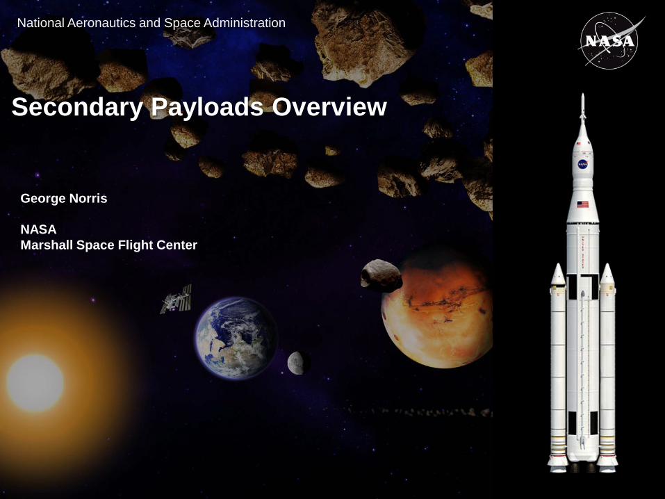
National Aeronautics and Space Administration
Secondary Payloads Overview
George Norris
NASAMarshall Space Flight Center
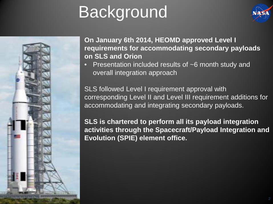
On January 6th 2014, HEOMD approved Level I requirements for accommodating secondary payloads on SLS and Orion• Presentation included results of ~6 month study and
overall integration approach
SLS followed Level I requirement approval with corresponding Level II and Level III requirement additions for accommodating and integrating secondary payloads.
SLS is chartered to perform all its payload integration activities through the Spacecraft/Payload Integration and Evolution (SPIE) element office.
Background
2
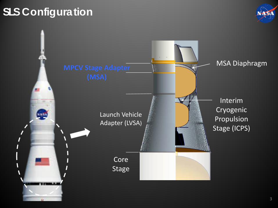
SLS Configuration
Core Stage
MPCV Stage Adapter(MSA)
Interim Cryogenic Propulsion
Stage (ICPS)
Launch Vehicle Adapter (LVSA)
MSA Diaphragm
3
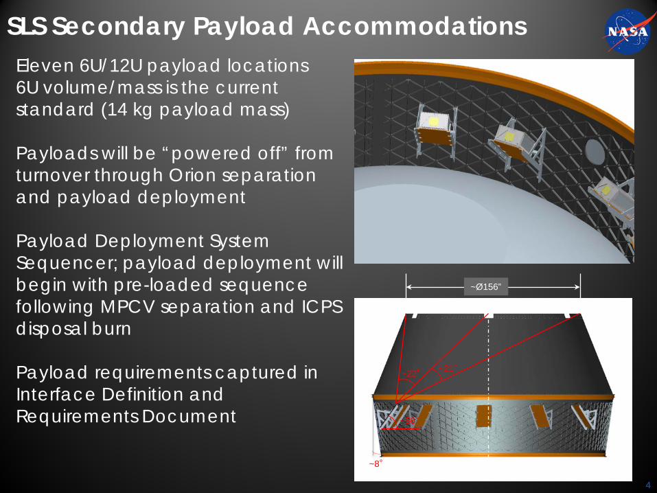
SLS Secondary Payload AccommodationsEleven 6U/12U payload locations6U volume/mass is the current standard (14 kg payload mass)
Payloads will be “powered off” from turnover through Orion separation and payload deployment
Payload Deployment System Sequencer; payload deployment will begin with pre-loaded sequence following MPCV separation and ICPS disposal burn
Payload requirements captured in Interface Definition and Requirements Document
4
~56°
~22°~21°
~Ø156”
~8°
4
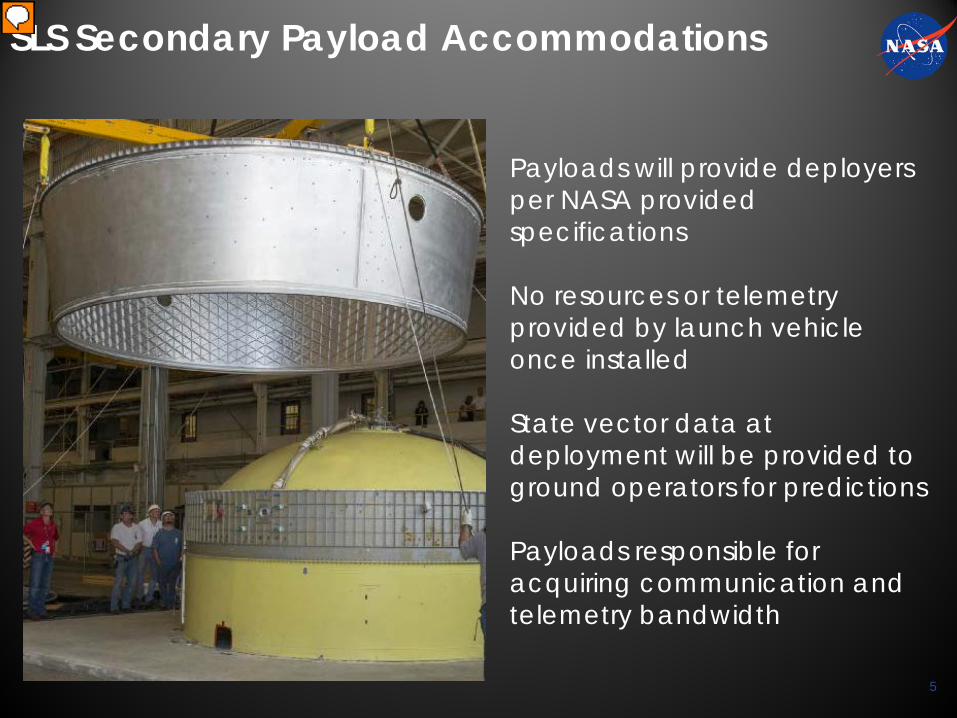
SLS Secondary Payload Accommodations
Payloads will provide deployers per NASA provided specifications
No resources or telemetry provided by launch vehicle once installed
State vector data at deployment will be provided to ground operators for predictions
Payloads responsible for acquiring communication and telemetry bandwidth
5
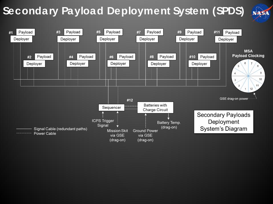
Secondary Payload Deployment System (SPDS)
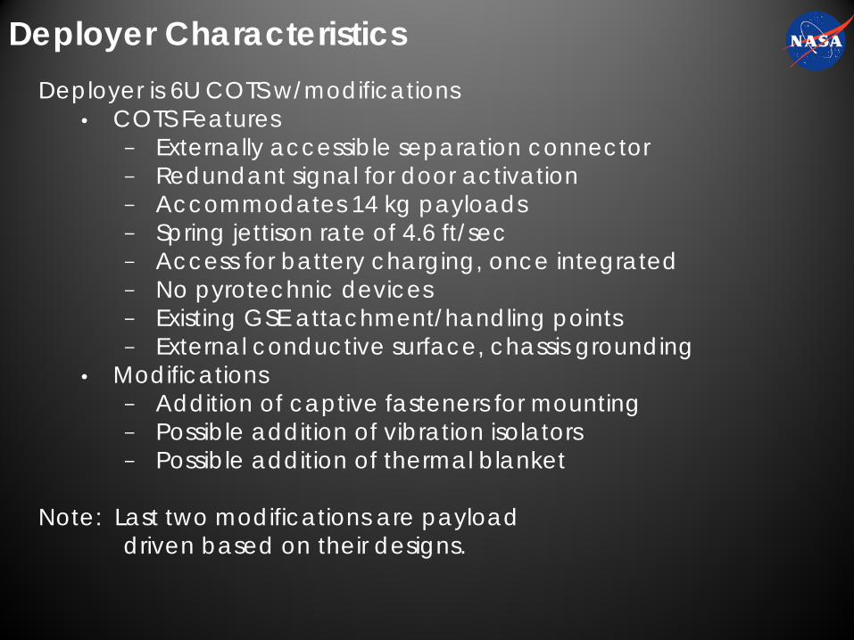
Deployer CharacteristicsDeployer is 6U COTS w/modifications
• COTS Features− Externally accessible separation connector− Redundant signal for door activation− Accommodates 14 kg payloads− Spring jettison rate of 4.6 ft/sec− Access for battery charging, once integrated− No pyrotechnic devices− Existing GSE attachment/handling points− External conductive surface, chassis grounding
• Modifications− Addition of captive fasteners for mounting− Possible addition of vibration isolators− Possible addition of thermal blanket
Note: Last two modifications are payloaddriven based on their designs.
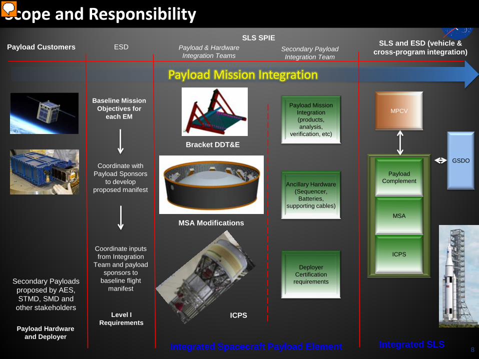
Secondary Payload Integration Team
SLS SPIESLS and ESD (vehicle &
cross-program integration)
Deployer Certification
requirements
Ancillary Hardware (Sequencer,
Batteries, supporting cables)
Payload Complement
MSA
ICPS
MPCV
GSDO
Payload Customers
Payload Mission Integration
Secondary Payloads proposed by AES, STMD, SMD and
other stakeholders
Scope and Responsibility
Integrated SLS
ESD
Coordinate with Payload Sponsors
to develop proposed manifest
Coordinate inputs from Integration
Team and payload sponsors to
baseline flight manifest
Baseline Mission Objectives for
each EM
8
Level I Requirements
Payload Mission Integration (products, analysis,
verification, etc)
MSA Modifications
Bracket DDT&E
ICPS
Integrated Spacecraft Payload Element
Payload & Hardware Integration Teams
Payload Hardware and Deployer
8
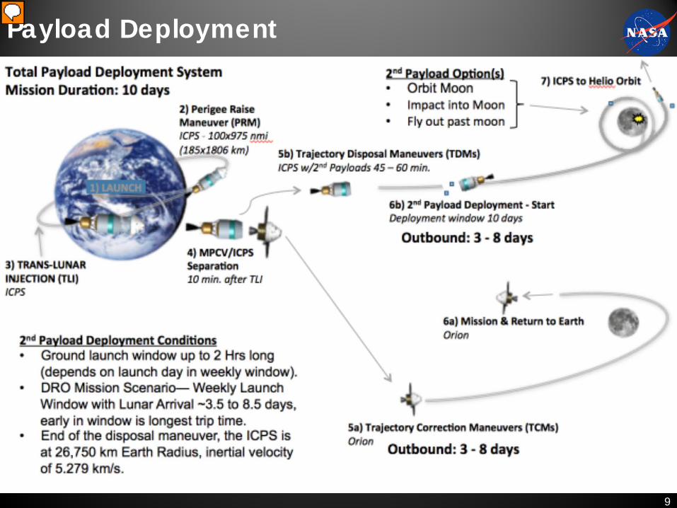
Payload Deployment
9
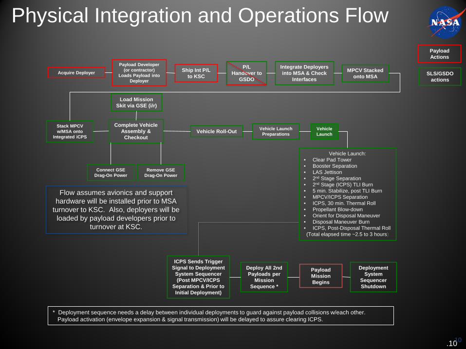
Physical Integration and Operations Flow
.10
Acquire Deployer
Payload Developer (or contractor)
Loads Payload into Deployer
Ship Int P/L to KSC
Integrate Deployers into MSA & Check
Interfaces
Connect GSE Drag-On Power
MPCV Stacked onto MSA
Complete Vehicle Assembly &
Checkout
Load Mission Skit via GSE (i/r)
Vehicle Roll-Out
Remove GSE Drag-On Power
Vehicle Launch Preparations
Vehicle Launch
Vehicle Launch:• Clear Pad Tower• Booster Separation• LAS Jettison• 2nd Stage Separation• 2nd Stage (ICPS) TLI Burn• 5 min. Stabilize, post TLI Burn• MPCV/ICPS Separation• ICPS, 30 min. Thermal Roll• Propellant Blow-down• Orient for Disposal Maneuver• Disposal Maneuver Burn• ICPS, Post-Disposal Thermal Roll(Total elapsed time ~2.5 to 3 hours)
Deploy All 2nd Payloads per
Mission Sequence *
ICPS Sends Trigger Signal to Deployment
System Sequencer (Post MPCV/ICPS
Separation & Prior to Initial Deployment)
Deployment System
Sequencer Shutdown
* Deployment sequence needs a delay between individual deployments to guard against payload collisions w/each other.Payload activation (envelope expansion & signal transmission) will be delayed to assure clearing ICPS.
Flow assumes avionics and support hardware will be installed prior to MSA
turnover to KSC. Also, deployers will be loaded by payload developers prior to
turnover at KSC.
Stack MPCV w/MSA onto
Integrated iCPS
Payload Mission Begins
Payload Actions
SLS/GSDO actions
P/L Handover to
GSDO
10
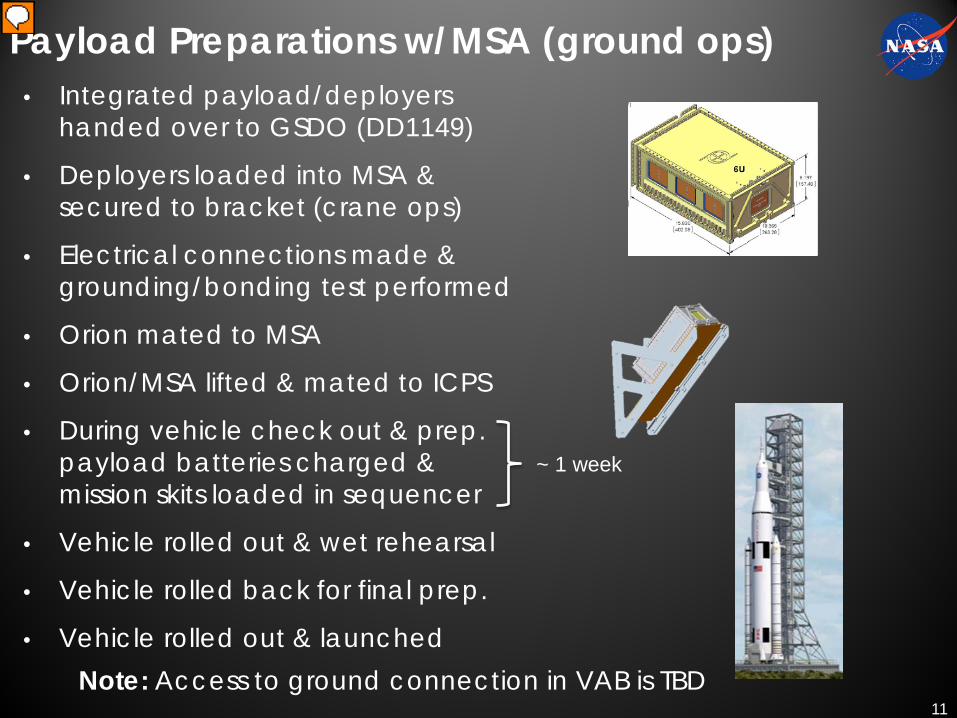
Payload Preparations w/MSA (ground ops)• Integrated payload/deployers
handed over to GSDO (DD1149)
• Deployers loaded into MSA & secured to bracket (crane ops)
• Electrical connections made & grounding/bonding test performed
• Orion mated to MSA
• Orion/MSA lifted & mated to ICPS
• During vehicle check out & prep. payload batteries charged & mission skits loaded in sequencer
• Vehicle rolled out & wet rehearsal
• Vehicle rolled back for final prep.
• Vehicle rolled out & launched
~ 1 week
Note: Access to ground connection in VAB is TBD11
Verification and CoFR• Payloads will be responsible for providing verification data for
requirements and interfaces captured in ICD• Direct Requirements flow down, Interface Requirements, Derived
requirements• Deployer verification will be provided by LSP for payloads utilizing their
procurement activity.
• Safety verification will be accomplished through proposed safety review process, expected at Phase III review
• Verification will accomplish certification of deployer, payload and integrated payload certification for EM-1
• Certificate of Flight Readiness (CoFR) endorsements will be required from payloads to support integrated payload complement and vehicle flight readiness
12
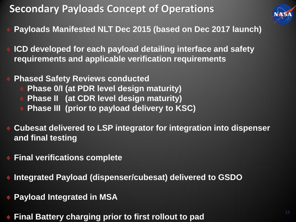
Secondary Payloads Concept of Operations
♦Payloads Manifested NLT Dec 2015 (based on Dec 2017 launch)
♦ ICD developed for each payload detailing interface and safety requirements and applicable verification requirements
♦Phased Safety Reviews conducted♦Phase 0/I (at PDR level design maturity)♦Phase II (at CDR level design maturity)♦Phase III (prior to payload delivery to KSC)
♦Cubesat delivered to LSP integrator for integration into dispenser and final testing
♦Final verifications complete
♦ Integrated Payload (dispenser/cubesat) delivered to GSDO
♦Payload Integrated in MSA
♦Final Battery charging prior to first rollout to pad13
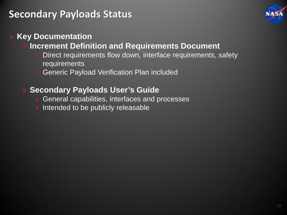
Secondary Payloads Status
♦Key Documentation♦ Increment Definition and Requirements Document
♦ Direct requirements flow down, interface requirements, safety requirements
♦ Generic Payload Verification Plan included
♦Secondary Payloads User’s Guide♦ General capabilities, interfaces and processes♦ Intended to be publicly releasable
14