georgia telecommunsications design manual · web viewdesign manual gtdm march 1, 2007 state of...
TRANSCRIPT

State of Georgia
Telecommunications Design Manual
GTDMMarch 1, 2007
State of GeorgiaTelecommunications Design Manual
GTDM
GSFICGeorgia State Financing and Investment Commission
March 1, 2007
ii

Publication Designation
State of Georgia Telecommunications Design Manual (GTDM)
Subject
Telecommunications, Networking and Information Transport Systems
Effective Date
March 1, 2007
Supersedes
State of Georgia Telecommunications Design Manual, March 1, 2003State of Georgia Telecommunications Design Manual, July 1, 2002Telecommunications AEC Design Manual, September, 2001
Scheduled Review
Twelve months from the effective date.
Authority
Georgia Statewide Technical Committee, serving OPB and GSFIC by delegation jointly under direction of their Administrative sections.
Overview
The intent of this document is to provide guidance to professionals engaged in designing and constructing projects for the State of Georgia, all of which usually include a telecommunications component. The design of any telecommunications Information Transport Systems (ITS) requires the use of a BICSI Registered Communications Distribution Designer who will retain full responsibility for the design of each telecommunications distribution system
This document addresses the technical aspects of telecommunications Information Transport Systems deployment. Administrative procedures are a separate GSFIC/OPB document. The GSFIC Construction Manual inserts this document in its telecommunications section to support all construction financed by the state.
Significant changes in technology and standards have occurred since the 2001 publication. Those changes have been incorporated into this revision. One major revision is the addition of Category 6 cabling which is the result of ratification of the standard for Category 6 cabling by ANSI/TIA/EIA in 2002
iii

The Georgia Technology Authority (GTA) is responsible for approving/accepting all telecommunications systems in all state owned or leased buildings. Stakeholders external to the Georgia Technology Authority (other state agencies) and external to the State of Georgia have reviewed and approved this revision.
Telecommunications design documents prepared by other agencies (Board of Regents, Georgia Building Authority, Georgia Property Commission, etc.) have been reviewed and are addressed or included as part of this document. This helps the relevancy of the document and adds significantly to the technological merit of this document. Any Georgia Agency may bring additional requirements for design or installation of ITS to the attention of the committee for review and inclusion.
Note: The Governor’s Office of Planning and Budget (OPB) is responsible for state agency budgeting activities. The Georgia State Financing and Investment Commission (GSFIC) is responsible for the funding of state construction projects and their oversight. The Georgia Technology Authority, (GTA) is responsible for upholding technology requirements delivering state agencies high quality telecommunications Information Transport System products and services.
iv

FORWARD
In today’s environment, the usability of state facilities is being determined more and more by the technology resources present. Proper planning, design, and installation of telecommunications technology based on current standards and proven practices are critical components in ensuring that space developed by the State of Georgia is of highest utility not only for the present, but well into the future. The Georgia Telecommunications Design Manual developed and updated on a regular basis by a team of individuals from state government and private enterprise, serves as the basis for ensuring that all state projects include consistent, standards-based, high quality telecommunications technology resources.
Dr. Tom MaierAssistant Vice Chancellor for Information TechnologyBoard of RegentsUniversity System of Georgia
v

EXECUTIVE SUMMARY
The State of Georgia’s Telecommunications Design Manual (GTDM) was first produced in 2001, with revisions in 2002 and 2003. This current revision (2007) seeks to enhance the last edition of the GTDM by streamlining and reorganizing many elements to present information in a more concise, user-friendly manner.
The Georgia Statewide Technical Committee is responsible for the content of the GTDM. This committee consists of state agency officials and industry subject matter experts tasked with producing and continuously maintaining this manual. The Georgia Statewide Technical Committee is an open committee and participation of volunteers from Georgia State Agencies, ITS Industry, Engineers, Planners and Architects is welcomed. This manual is presented as a living document and is the result of the Georgia Statewide Technical Committee’s professional commitment to Georgia.
The GTDM is written to provide standards based ITS requirements to State of Georgia Agencies, Architects and Design Engineers involved with the design and construction of State facilities. The GTDM is the only approved document to be used in the design and installation of Information Transport Systems (ITS) for the State of Georgia.
The Georgia Technology Authority (GTA), the Georgia State Financing and Investment Commission (GSFIC) and the Governor’s Office of Planning and Budget (OPB) along with representatives from many other state agencies have participated in the development of this manual. This manual is based upon the most current available literature; codes, standards and industry accepted practices available at the time of publication.
Professionals inside and outside state government who are involved in the design and construction of state facilities, along with representatives from state agencies, shall use the GTDM to insure that each facility’s Information Transport System is constructed with the latest standards of the telecommunications industry.
The intent of the authors is to provide guidance and assistance to the designers, builders and other contractors including any other appropriately allied trade professional who may become involved with the design and construction of telecommunications Information Transport Systems in any State facility. This includes the design and deployment of Information Transport Systems that provide voice, data, video and other low voltage signaling functions, and using types of twisted pair, coax and optical fiber cable, connectors, and other hardware in the provision of acceptable work area outlets for any telecommunication device which requires connection to other devices, networks or information services which serve the needs of the building’s occupants and the State of Georgia.
Ongoing, rapid changes in the telecommunications Information Transport System technology and requirements for compatibility with the statewide communications network necessitate the active involvement of appropriate state oversight of the OPB, the GSFIC and the GTA in active review and advisory roles, from pre-design through the completion of construction. GTA has been tasked by OPB and GSFIC with the review and inspection role of all ITS design and installation.
Accordingly, this Manual seeks to provide guidance and establish requirements based on accepted North American Standards, and Codes, both Federal and State.
vi

References to these Standards and Codes are included in the GTDM. The Manual’s Table of Contents is in itself a resource for interested parties. It points
to various topics which may need to be addressed on any given Project with regard to telecommunications Information Transport Systems, including Code and Standards compliance; effective, reliable and acceptable infrastructure design; and comprehensive installation, testing and administrative practices and procedures.
The order of the subjects covered approximates the order of construction, from concept to completion. Furthermore, the content of the Table, and therefore the Manual itself, tends to flow from the general to the specific and from the conceptual to the technical. This format is intended to make the Manual useful to as wide a readership as possible. Administrators will find it useful to refer to the Manual during the conceptual stage of a project, to help them construct an outline of needs and budgetary requirements. Designers can use it as a reference to ascertain technical requirements and State of Georgia preferences. There is a Glossary of terms included with the GTDM. The GTDM is not intended for use as a template.
The Georgia Technology Authority and the Georgia State Financing and Investment Commission recognize and emphasize their awareness of and insistence upon the uniqueness of every project. As such, each project requires the individual and collaborative attention of the owner, occupant, design team, GTA, and the funding entity.
The Manual addresses both inside and outside plant telecommunications. While comprehensive in nature, its use may bring to the mind of the reader questions about topics not touched on, or may beg for more clarity or detail in specific areas of design and construction. Referenced early in the design and construction process, these questions and concerns will be raised, addressed, and resolved in a timely manner, and the purpose of the Manual will have been fulfilled. Reducing or eliminating changes to designs during or after construction is the states goal.
This design manual establishes a strategic direction for the physical connection of communications devices in State of Georgia facilities. Architects, Engineers and State Agency officials are required to use this manual as a design reference for all telecommunications Information Transport Systems. A properly designed and constructed telecommunications Information Transport System shall be adaptable to change over the life of the building. The criteria contained within this manual are subject to revisions and updates due to technological advances within the telecommunications industry. Telecommunications has a financial impact on all construction and renovation of State of Georgia buildings. It is expensive and time-consuming to continually change cabling and infrastructure systems to support different network configurations, computer systems and the relocation of employees. Therefore, it is very important that the design and construction of new or renovated buildings effectively avoids obsolescence. That is why in recent years, national and international standards organizations have been developing standards for the various elements of telecommunications cabling systems. The State of Georgia’s implementation of these standards ensures a flexible, uniform telecommunications environment and:
Provides telecommunications architecture based on recognized standards to support efficient, long-lasting, cost-effective operations.
vii

Reduces the amount of time required to install new networks or to reconfigure existing local area networks.
Provides the flexibility to operate multiple high bandwidth technologies on a single structured cabling system.
Eliminates the cost of installing non-standard, proprietary, vendor-specific cabling by providing standards-based cabling systems that will support a wide variety of telecommunications equipment.
Improves network manageability and facilitates automated cabling system management through the use of uniform and industry standard identification and numbering schemes.
Allows for the growth of anticipated high speed, high bandwidth Local Area Networks (LANs), Metropolitan Area Networks (MANs) and Wide Area Networks (WANs) that may be required by future specialized applications.
State Agency Design Requirements:Pre-design Stage
When developing a Pre-design plan for a new building or a renovation of an existing site, the Using Agency shall include the GTDM as part of the package. The Architect shall be made aware that all of the requirements in the GTDM for designing Information Transport Systems must be followed. The written approval by GTA shall be part of the completed Pre-design Architectural package.
Design / Construction StageWhen developing design/construction documents for renovations or new buildings the
Using Agency Architect shall include the GTDM as part of the package. The Architect shall be made aware that all of the requirements in the GTDM for designing Information Transport Systems must be followed. The written approval by GTA shall be part of the completed Construction Architectural bid package.
The designer of the telecommunications Information Transport System shall be aware of the role of the Using Agency. The Using Agency assists in the following roles:
To establish a budget for telecommunications Information Transport Systems and to provide financial support for the system(s).
Ensure that a virtual team for the design and implementation of telecommunications is established and shall include the following participants at a minimum: 1) the Architect, 2) the GTA/RCDD, 3) the Agencies IT representative and 4) the Using Agencies Project Manager and other participants as necessary.
viii

Assure compliance with state policies, codes, standards and this Telecommunications Design Manual.
Ensure that only professionals licensed to operate within the State of Georgia are allowed to install telecommunications Information Transport Systems cabling and support infrastructure.
ix

ACKNOWLEDGEMENTS
The Georgia Technology Authority, the Georgia State Financing and Investment Commission, the Governor’s Office of Planning and Budget and the editors of this document wish to thank our industry partners and those state employees who donated their time and effort to the development and production of this document.
Statewide Technical Committee Members
Name Title Organization
Tracey Kniery Regional Manager Siemon Bob Scott District Manager Commscope Enterprise
SolutionsNancy Chinigo Regional Manager General CableFrank Nesbitt Network Specialist Department of Juvenile
JusticeGreg Keys RCDD Consulting ServicesNikko Sarris Manager Molex Inc.Dr. Tom Maier Assistant Vice Chancellor for
Information Technology Georgia Board of Regents
Vic Turner Engineer/RCDD CANA Communications Lewis Hauck Engineer Department of CorrectionsChuck Rich RCDD Leviton, Government
ServicesCraig Carroll Project Manager Dynalectric CompanyJason Krauskopf Director Superior EssexPaul Norris Manager Commscope Inc.Jeremy Gilbertson Regional Manager GraybarAl Myers Regional Manager WindstreamWilliam Lee Engineer TCOM Design Inc.Mark Skaggs Regional Manager Cabling Systems Inc.Larry Jennings Electrical Engineer Georgia State Financing
and Investment Commission
Adrian Whitaker Regional Engineer, RCDD Georgia Technology Authority
Daryl Seay Regional Engineer, RCDD Georgia Technology Authority
Phil Pearce Senior Territory Manager, RCDD Hubbell Premise CablingMihai Sterescu Electrical Engineer, RCDD Barnett Consulting
Engineers, Inc.Rick Henderson Regional Manager Madigan, McCune &
Associates, Inc.
x

Scott Bryant Regional Manager, RCDD Panduit CorporationGreg Inman RCDD PSA
Timothy Trotter Electrical Engineer, PE, RCDD Nottingham, Brook and
Pennington, Consulting Engineers
Mickey Pietrocola Infrastructure Division Manager, RCDD
Pearlnet, LLC
Dave Adams AIA, Architect Georgia State Financing & Investment Commission
Ron Nawrocki Manager, Capital Budgeting Governor’s Office of Planning and Budget
Committee Chairman
Glenn M. Bishop Regional Engineer, RCDD Georgia Technology Authority
Editor
Rhett Huber Communications Specialist Georgia Technology Authority
xi

CONTENTS
GENERAL REQUIREMENTS 1
1.0 Introduction 1
1.1 Background 1
1.2 Design Manual Scope 1
1.3 Purpose of This Manual 2
1.4 The Statewide Telecommunications Technical Committee Approach Error! Bookmark not defined.
1.5 The Statewide Telecommunications Technical Committee Objective 4
1.6 Telecommunications Design Intent 4
1.7 Telecommunications Budget 4
1.8 Regulatory Codes and Standards 51.8.1 Regulatory Agencies 51.8.2 National Electrical Code, NFPA 70 51.8.3 ANSI/TIA/EIA Standards 61.8.4 Local Area Network Ethernet Standard, IEEE 802.3 (series) 81.8.5 BICSI Telecommunications Distribution Methods Manual 91.8.6 Local Code and Regulatory Compliance 91.8.7 Adherence to Reference Documents 9
1.9 Industry Standard Drawings and Specifications 101.9.1 Overview 101.9.2 Applicable Drawings 101.9.3 Required Specifications 13
1.10 Low Voltage Designer and Contractor Qualifications 131.10.1 Telecommunications Designer 131.10.2 Telecommunications Contractor 131.10.3 Change Approvals 141.10.4 Required Inspections 141.10.5 Prime Vendor/Contractor 14
1.11 Overall Quality Assurance 14
1.12 Submittals and Documents Review 15
1.13 Project Record Documents 15
1.14 Post Construction Warranties and Other Requirements 15
1.15 The Georgia Technology Authority (GTA) 16
xii

1.16 Role of the GTA Registered Communications Distribution Designer 16
1.17 Role of the State Agency 17
1.18 Requirements for Information Transport Systems 181.18.1 Compliance with Standards Based Designs 181.18.2 Category 6 Cabling 181.18.3 Provisioning 191.18.4 Optical fibers 191.18.5 Pathways 191.18.6 Grounding and Bonding 191.18.7 Ethernet 201.18.8 Administration 20
1.19 Georgia Technology Authority - Managed Cabling Services 20
TELECOMMUNICATIONS SPACES 20
2.0 Common Requirements for Telecommunications Spaces 202.0.1 Definition 202.0.2 Architectural Requirements 20
A. Size 20B. Location 21C. Finishes 22D. Doors 22E. Fire Extinguishers 22F. Room Identifiers 22
2.0.3 Structural Requirements 22A. Floor Loading 22B. Floor Sleeves and Slots 22
2.0.4 Mechanical Requirements 23A. HVAC 23B. Fire Suppression 24
2.0.5 Electrical Requirements 24A. Grounding & Bonding 24B. Power 24C. Lighting 24
2.0.6 Build-out Requirements 25A. Plywood Backboards 25B. Equipment Racks 25C. Cable Management for Equipment Racks 26D. Overhead Ladder Racking 26E. Bonding Busbar 27
2.1 Service Entrance Facility Room (SEF) 272.1.1 Definitions 272.1.2 Architectural Requirements 28
A. Size 28B. Location 28C. Finishes 28D. Doors 28
2.1.3 Structural Requirements 28A. Floor Loading 28B. Floor Sleeves and Slots 28
2.1.4 Mechanical Requirements 28
xiii

A. HVAC 28B. Fire Suppression 29
2.1.5 Electrical Requirements 29A. Grounding and Bonding 29B. Power 29C. Lighting 29
2.1.6 Build-out Requirements 29A. Plywood Backboard 29B. Overhead Ladder Racking 29C. Bonding Busbar 29
2.2 Equipment Rooms (ER) 302.2.1 Definition 302.2.2 Architectural Requirements 30
A. Size 30B. Location 30C. Finishes 30D. Doors 30E. Fire Extinguishers 30F. Access Floors 30G. Room Identifier 31
2.2.3 Structural Requirements 31A. Floor Loading 31B. Floor Sleeves and Slots 31
2.2.4 Mechanical Requirements 31A. HVAC 31B. Fire Suppression 31
2.2.5 Electrical Requirements 31A. Grounding & Bonding 31B. Power 31C. Lighting 31
2.2.6 Build-out Requirements 31A. Plywood Backboard 31B. Equipment Cabinets 32C. Equipment Racks 32D. Horizontal Cable Management 32E. Vertical Cable Management 32F. Cable Tray 32G. Bonding Busbar 32H. Overhead Ladder Racking 32I. Under Raised Floor Cable Tray 32J. Telecommunications Grounding & Bonding 33
2.3 Telecommunications Rooms 332.3.1 Definition 332.3.2 Architectural Requirements 34
A. Size 34B. Location 34C. Finishes 34D. Doors 34
2.3.3 Structural Requirements 34A. Floor Loading 34B. Floor Sleeves and Slots 35
2.3.4 Mechanical Requirements 35A. HVAC 35B. Fire Suppression 35
xiv

2.3.5 Electrical Requirements 35A. Power 35B. Lighting 35
2.3.6 Build-out Requirements 35A. Plywood Backboards 35B. Equipment Cabinets 35C. Equipment Racks 35D. Horizontal Cable Management 35E. Vertical Cable Management 35F. Cable Tray 36G. Bonding Busbar 36H. Overhead Ladder Racking 36I. Under Raised Floor Cable Tray 36
PATHWAYS 37
3.0 Common Requirements 37
3.1 Definitions: 373.0.2 Architectural Requirement 37
3.1 Intra-Building (within Buildings) Backbone Pathways 383.1.2 Structural Requirements 383.1.3 Electrical Requirements 383.1.4 Build-Out Requirements 38
A. Conduits 38B. Sleeves & Slots 40C. Cable Tray 40D. Firestopping 40
3.1.5 Administration & Labeling 40
3.2 Inter-Building (between Buildings) Backbone Pathways 403.2.1 Definitions 403.2.2 Site Requirements 403.2.3 Structural Requirements 403.2.4 Electrical Requirements 403.2.5 Build-Out Requirements 40
A. Conduits and Duct Banks 40B. Hand Holes 40C. Maintenance Holes 40D. Vaults 40E. Aerial Distribution 40
3.2.6 Administration & Labeling 40
3.3 Horizontal Pathways 403.3.1 Definitions 403.3.2 Support Requirements 403.3.3 Electrical Requirements 40
A. Grounding and Bonding 403.3.4 Build-out Requirements 40
A. Pathway Systems 40 Products 40B. Sleeves and Slots 40 Products (See 3.1.4 B for common requirements ) 40 Execution 40
xv

C. Cable Tray 40 Products (Also see 3.1.4 C) 40 Execution 40D. Alternate Cable Support 40 Products 40E. Boxes 40F. Poke-throughs 40G. Utility Columns 40
CABLING AND COMPONENTS 40
4.0 Common Requirements 40
4.1 Horizontal Distribution Cabling 404.1.1 Definitions 404.1.2 Build-out Requirements 40
A. Copper 40B. Fiber 40C. Wireless 40
4.1.3 Administration & Labeling 404.1.4 Other Cabling Systems/Issues 40
4.2 Intra-Building (within buildings) Backbone 404.2.1 Definitions 404.2.2 Build-out Requirements 40
A. Copper 40B. Fiber 40
4.3 Inter-Building (between Buildings) Backbone 404.3.1 Definitions 404.3.2 Common Requirements 404.3.3 Build-Out Requirements 40
A. Copper 40B. Optical fiber Backbone Cabling 40
4.3.4 Administration and Labeling 40
APPENDICIES
APPENDIX A 40
GLOSSARY OF CABLING AND TELECOMMUNICATIONS TERMS AND CONCEPTS 40
APPENDIX B - REFERENCES 40
APPENDIX C – CONTACT INFORMATION 40
xvi

APPENDIX D 40
CSI MASTER FORMAT AND SAMPLE SPECIFICATIONS 40
SAMPLE SPECIFICATIONS 40
xvii
GENERAL REQUIREMENTS1.0 Introduction
The general requirements set forth here are designed to assist in planning for new construction, renovations and other installations required by state agencies. In general, these requirements apply to all installations of Information Transport Systems, no matter how large or small. State law governs who can legally install Information Transport Systems under the Official Code of Georgia (OCG) and must be adhered to for all installations. The following requirements have been established from input by all state agencies.
This manual does not specifically address safety issues associated with its use. It is the responsibility of the user of this manual to determine and use the applicable safety and health practices of OSHA, NEC, NESC and any other life/safety standard. The State of Georgia shall not be liable with respect to any liability, loss or damage caused directly or indirectly by application of this manual.
No project is so important, nor any completion deadline so critical as to justify the non-compliance with safety practices, industry codes or required standards.
1.1 Background
Earlier State of Georgia Telecommunications Manuals focused on building cabling only and were incomplete. As development progressed on these earlier manuals, technology advanced and necessitated continuous revisions of those documents. The last telecommunications manual was published in 2003. This 2007 manual replaces any/all previously published guidelines or directives with respect to newly constructed, renovated or ITS installation projects. Guidelines published by many other Agencies have been reviewed and included in this manual. This manual addresses expanded requirements for telecommunications and includes Outside Plant (OSP) Distribution. These expanded requirements emanated from the work of the Georgia Statewide Telecommunications Technical Committee. This committee consists of state agency professionals, local government agency officials, manufacturers, vendors, Architects, Professional Engineers, higher education representatives and other design professionals with extensive experience in the telecommunications field.
1.2 Design Manual Scope
This manual is applicable to all using agencies and institutions of higher education (hereinafter collectively referred to as "Agencies"). The Georgia Building Authority and the Georgia Property Commission are included. This manual provides telecommunications design and installation information for the following:
1
Newly constructed buildings
Buildings undergoing renovations
New long-term leased occupancy spaces
New multi-building sites that use state owned optical fiber or copper cables
State occupied spaces requiring new Information Transport Systems
1.3 Purpose of This Manual
Effective telecommunications and networking cannot be accomplished without adherence to standards. Additionally cabling infrastructure costs cannot be contained without adherence to sound installation and management practices. To ensure that the future telecommunications and connectivity needs of agencies are met in a cost-effective manner, this manual confirms the State of Georgia’s support for ANSI/TIA/EIA and IEEE standards for telecommunications.
The following standards are applicable to telecommunications cabling:
The American National Standards Institute (ANSI) approves standards as having been properly developed.
The Telecommunications Industry Association (TIA) develops standards for cables.
The Electronics Industry Association (EIA) focuses on physical device standards.
The Institute of Electrical and Electronics Engineers (IEEE) publishes networking and telecommunications standards
This manual is intended to give required minimums for telecommunications in state facilities. This manual addresses the physical pathways, media, and cable administration practices. Thus the purpose of this manual is threefold:
To provide direction which eliminates costly changes
To enable the planning of telecommunications facilities with little knowledge of the specific electronic equipment that will be installed
To define a generic information transport system (ITS) that will support Agency needs in
a multi-vendor and multi-product environment.
This manual provides: The general ITS requirements adopted by the State of Georgia Reference materials and web sites related to the ITS requirements
2

Direction on how state agencies shall typically address the requirements.
1.4 The Statewide Telecommunications Technical Committee Approach
Whenever ANSI/TIA/EIA or IEEE introduces major modifications, this will trigger a committee review of those requirements by the Statewide Telecommunications Technical Committee. As reviews are conducted, the review dates and recommended modifications will be added to this manual.ANSI/TIA/EIA and IEEE standards referenced herein are adopted in both their present state and as amended or replaced unless otherwise indicated in the requirements provided below. Every effort will be made to ensure that these requirements are reviewed annually.
The committee is called to meeting when technology changes are requested by State Agencies or when ANSI/TIA/EIA or IEEE introduces major modifications.The chairman offers these recommendations of State Agency requested changes or changes adopted by ANSI/TIA/EIA or IEEE for inclusion in the GTDM to the committee. One such recommendation follows;
The recommendation was presented to follow the ITS cabling industry practice of using a Structured Cabling System (SCS). The adoption of this recommendation was accepted and is now approved. Other cabling systems may be installed in addition to the SCS but as a minimum the state now requires that an SCS be installed. A properly designed SCS allows the designer and installer to cable a building for telecommunications needs without knowing specifically what equipment will be utilized. The SCS is geared for long-term stability and flexibility and is based on the idea of cabling buildings once. The SCS approach allows the cable and telecommunications work area outlets to remain unchanged as connections and services vary.
There are typically eight major components of the SCS as follows: 1) Service Entrance Facilities 2) Main Equipment Room 3) Telecommunications Room 4) Backbone Cabling 5) Horizontal Cabling 6) Work Area Outlets 7) Grounding and Bonding and 8) Administration and Labeling.
Due to the legacy placement of cabling on many College and University campuses, in some instances it may be necessary to deviate from the SCS scheme and continue with the current scheme. OSP pathways and Backbone Cabling that will be customer owned shall be considered part of the SCS. Exceptions to an SCS installation may be allowed but must be approved in writing by a GTA/RCDD.
3

To become a member of the Statewide Telecommunications Technical Committee contact your regional Georgia Technology Authority/ Regional Communications Distribution Designer (GTA/RCDD) or the Georgia State Financing and Investment Commission (GSFIC). See Appendix (C).
1.5 The Statewide Telecommunications Technical Committee Objective
The Statewide Telecommunications Technical Committee’s objective is as follows:
To explain the interplay of industry-supported standards, Georgia laws and sound enterprise business practices in providing an architectural foundation for telecommunications and networking for Georgia’s agencies.
To provide the agency with state requirements related to networking and telecommunications infrastructure development, maintenance and administration.
To provide a framework for the integration of telecommunications into the design and construction of state facilities.
1.6 Telecommunications Design Intent
It is desired by the State of Georgia to have a uniform ITS cabling plan in each building/facility that supports voice, data, image, and video distribution to allow for flexible changes, office renovations, equipment migrations and constant upgrades. This cabling system shall be based on industry standard structured cabling systems that are not proprietary and conform to current ANSI/TIA/EIA Commercial Building Cabling Standards.
It is the intent of this manual to assure adherence to nationally recognized codes and standards. For those involved in designing telecommunications infrastructure and cabling systems for all state use buildings, the GTA/RCDD will provide professional design review and inspection assistance to the Agency and other design professionals.
1.7 Telecommunications Budget
The telecommunications budget for a project shall include the costs associated with engineering, installation, testing and documentation for a complete SCS. The engineering cost shall include, design, engineering, supervisory and project management functions. The installation cost shall include the actual installation labor and materials costs for each SCS installed. Testing and documentation costs shall include the associated electronic test report documentation, electronic and hard copies of all as-built drawings and the software used to read/view the electronic testing and as-built drawings.
The overall budget shall include all of the above for the following items:
The inter-building cabling and support infrastructure for voice, data and video
4

The intra-building cabling and support infrastructure for voice, data and video
All devices for CATV connections
All interconnect and patch cables.
At this time, active and passive devices for all network connections (i.e. switches, routers, optical fiber devices, telephone systems/sets etc…) shall not be included in the construction phase. Electronic network equipment shall be provided by the using agency.
1.8 Regulatory Codes and Standards
1.8.1 Regulatory AgenciesCurrently, the following agencies and their codes, standards and regulations shall govern all telecommunications work performed for the State of Georgia.
Acronym Organization Web Site
ANSI American National Standards Institute www.ansi.orgASTM American Society for Testing Materials www.astm.orgBICSI Building Industry Consulting Service
International www.bicsi.org
BOCA Building Officials and Code Administrators International, Inc.
www.bocai.org
EIA Electronic Industries Alliance www.eia.orgEPA Environmental Protection Agency www.epa.govEPD - Georgia Georgia Environmental Protection Division www.dnr.state.ga.us/dnr/environFCC Federal Communications Commission www.fcc.orgICEA Insulated Cable Engineers Association, Inc. www.icea.netIEEE Institute of Electrical and Electronic Engineers,
Incwww.ieee.org
IEC International Electro-technical Commission www.iec.chISO International Organization for Standardization www.iso.chNEMA National Electrical Manufacturers Association www.nema.orgNFPA National Fire Protection Association www.nfpa.orgNEC (NFPA 70) National Electrical Code www.nfpa.orgOSHA Occupational Safety and Hazard Administration www.osha.govSCTE Society of Cable Telecommunications Engineers www.scte.orgRUS Rural Utilities Services www.rurdev.usda.gov/rus/TIA Telecommunications Industry Association www.tiaonline.orgUL Underwriters Laboratories www.ul.com
1.8.2 National Electrical Code, NFPA 70
5

The National Fire Protection Association has acted as the sponsor of the National Electrical Code (NEC) since 1911. The original Code was developed in 1897 as a result of the united efforts of various insurance, electrical, architectural, and allied interests. The purpose of the NEC is the practical safeguarding of persons and property from hazards arising from the use of electricity. The NEC provides the minimum code requirements for electrical safety. In telecommunications distribution design, the NEC must be used in concert with the ANSI/EIA/TIA standards identified below, which are intended to insure the performance of the telecommunications infrastructure. Designers shall always consult with the local municipal Authority Having Jurisdiction (Building/Fire Inspector), who may have additional, more stringent requirements, beyond those contained in the NEC.
The particular sections of the NEC of interest to designers and installers of telecommunications distribution, telecommunications systems, and information processing systems are:
Article 250 -- Grounding Article 517 -- Health Care Facilities Article 645 -- Information Technology Equipment Article 770 -- Optical Fiber Cables and Raceways Chapter 8 -- Communications Systems
The National Electrical Code is available from:
National Fire Protection Association 1 Batterymarch Park PO Box 9101 Quincy, MA 02269-9904
1.8.3 ANSI/TIA/EIA Standards
The Telecommunications Industry Association/Electronics Industry Association (ANSI/TIA/EIA) engineering standards and publications are designed to serve the public interest by eliminating misunderstandings between manufacturers and purchasers. The standards facilitate interchangeability and improvement of products, and assist the purchaser in selecting and obtaining the proper product for his particular need.
ANSI/TIA/EIA Standards are updated every 5 years. Due to the rapid changes in the telecommunications and electronics industries, ANSI/TIA/EIA publishes periodic Telecommunications System Bulletins (TSB) which provides additional guidance on technical issues that must be addressed prior to the next scheduled revision of the Standards. The information contained in TSBs is usually incorporated into the applicable Standard during the next Standard revision. Standards and publications are adopted by ANSI/TIA/EIA in accordance with American National Standards Institute (ANSI) patent policy.
ANSI/TIA/EIA Standards are available from:
6

Global Engineering Documents 15 Inverness Way East Englewood, CO 80112-5704 1-800-624-3974
Optical Fiber Systems Test Procedures, ANSI/TIA/EIA-526 (series)
ANSI/TIA/EIA-526 contains a series of test procedures developed to provide uniform procedures for testing all or part of optical fiber systems or subsystems intended for optical communications or data transmission use. The base document is ANSI/TIA/EIA-526.
Cabling Standard, ANSI/TIA/EIA-568 (series)
The ANSI/TIA/EIA-568 (series) is the Commercial Building Telecommunications Cabling Standard. This standard defines a generic telecommunications cabling system for commercial buildings that will support a multi-product, multi-vendor environment. It also provides direction for the design of telecommunications products for commercial enterprise.
The purpose of the standard is to enable planning and installation of building cabling with little knowledge of the telecommunications products that subsequently will be installed. Installation of cabling systems during building construction or renovation is significantly less expensive and less disruptive than after the building is occupied. ANSI/TIA/EIA-568 establishes performance and technical criteria for various cabling system configurations for interfacing and connecting their respective elements.
Pathways and Spaces, ANSI/EIA/TIA-569 (series)
The ANSI/EIA/TIA-569 (series) is the Commercial Building Standard for Telecommunications Pathways and Spaces. This standard recognizes three fundamental concepts related to telecommunications and buildings
(1) Buildings are dynamic.
Over the life of a building, or campus, remodeling is more the rule than the exception. The standard recognizes that changes will take place.
(2) Building telecommunications systems and media are dynamic.
Over the life of a building, or campus, both telecommunications equipment and cabling requirements change dramatically. The standard recognizes this fact by being as independent as possible from specific vendor equipment and media.
(3) Telecommunications is more than just voice and data connectivity.
7
Telecommunications also encompasses many other building systems including environmental controls, security, audio, television, sensing, alarms and paging.
Telecommunications includes all low voltage signal systems that convey information within or between buildings.
In order to have a building, or campus, successfully designed, constructed, and provisioned for telecommunications, it is imperative that the telecommunications design be incorporated during the preliminary architectural design phase. To accomplish this, the architect must work closely with the designated GTA/RCDD; and the Agency’s Facilities Coordinator.
Administration Standard, ANSI/TIA/EIA-606 (series)
The ANSI/TIA/EIA-606 (series) is the Administration Standard for the Telecommunications Infrastructure of Commercial Buildings. Administration of the telecommunications infrastructure includes documentation of cables, termination hardware, patching and cross-connection facilities, conduits, other cable pathways, telecommunications rooms, and other telecommunications spaces. The purpose of this standard is to provide a uniform administration scheme that is independent of applications, which may change several times throughout the life of a building. This standard establishes guidelines for owners, end users, manufacturers, installers, and facilities administrators involved in the administration of the telecommunications infrastructure.
Grounding and Bonding, ANSI/J-STD-607 (series)
The ANSI/J-STD-607 (series) is the Commercial Building Grounding and Bonding Requirements for Telecommunications. The National Electrical Code (NEC) provides grounding, bonding, and electrical protection requirements to ensure life safety. Modern telecommunications systems require an effective grounding infrastructure to insure optimum performance of the wide variety of electronic information transport systems that may be used throughout the life of a building. The grounding and bonding requirements of this standard are additional technical requirements for telecommunications that are beyond the scope of the NEC. These standards are intended to work in concert with the cabling topology specified in ANSI/TIA/EIA-568, and installed in the pathways and spaces designed in accordance with ANSI/TIA/EIA-569.
1.8.4 Local Area Network Ethernet Standard, IEEE 802.3 (series)
The State of Georgia typically utilizes the Ethernet LAN protocol at all facilities. All State of Georgia telecommunications infrastructure must be designed to support the Institute of Electrical and Electronic Engineers (IEEE) Ethernet 802.3 standards. Most State organizations are in the process of migrating to the 1000Base-X Gigabit Ethernet protocol based on the IEEE 802.3z standard. All newly installed cabling shall support this protocol. Careful consideration must be given to the multimode optical fiber distance limitations and signal loss limitations (less than 2.5 dB end-to-end) necessary to support the IEEE 802.3z protocol.
8
1.8.5 BICSI Telecommunications Distribution Methods Manual
BICSI is an ITS Association whose mission is to provide state-of-the-art telecommunications knowledge to the industry, resulting in good service to the end user. BICSI develops and publishes the Telecommunications Distribution Methods Manual (TDMM). The TDMM is not a code or standard. The TDMM is an extensive volume of information on the various aspects of telecommunications systems and telecommunications distribution. The TDMM provides discussions and examples of various engineering methods and design solutions that can be selected and employed in order to meet the requirements of the NEC and ANSI/TIA/EIA standards.
Additional BICSI Publications:
BICSI -- Cabling Installation ManualBICSI -- LAN Design ManualBICSI – Customer-Owned OSP Design Manual
BICSI publications are available from:
BICSI 8610 Hidden River Parkway Tampa, FL 33637-1000 1-800-242-7405
1.8.6 Local Code and Regulatory Compliance
Federal, state, and local codes, rules, regulations, and ordinances governing the work, are as fully part of this manual as if herein repeated or hereto attached. Contractors shall notify the agency immediately in writing of any possible code violations. Where the requirements of this manual are more stringent than applicable codes, rules, regulations, and ordinances, the GTDM requirements shall apply.
All pertaining statutes, ordinances, rules, codes, regulations, standards, and the lawful orders of all public authorities having jurisdiction over the construction of ITS will be followed in the design and installation of cabling systems. These include, without limitation, applicable building codes, and disability regulations (ADA), municipal codes, fire codes, state statutes and the regulations of the Occupational Safety and Health Administration (OSHA).
1.8.7 Adherence to Reference Documents This manual does not exclude any part of the ANSI/TIA/EIA standards but may recommend additional practices based upon field experience in state facilities. It is the responsibility of the designer to be familiar with the most current revision of the ANSI/TIA/EIA standards and to utilize the standards without exception unless recommended to do otherwise by this manual. Codes shall be followed; however, where they may differ with standards, the more stringent code requirement shall be followed.
9
1.9 Industry Standard Drawings and Specifications
1.9.1 Overview
The latest (2004) CSI Master Format Construction specifications shall apply to all projects. The telecommunications ‘T-Series’ drawings shall be included in addition to the other CSI Divisions. Some drawing elements may be combined onto a single sheet for smaller projects. Drawings required for a project shall be determined in the pre-design stage. Some projects may require all of these drawings and more to convey the intent of the necessary design intent of the ITS. Drawings shall be provided to address both inter-building and intra-building telecommunications needs based upon the scope of work developed during the pre-design stage of the project.
1.9.2 Applicable Drawings
T0 Series Campus or Site Plans – Exterior Pathways and Inter-building Backbones
T1 Series Layout of complete building(s) per floor – Serving Zone Boundaries, Backbone Systems and Horizontal Pathways
T2 Series Serving Zones Drawings – WAO Locations and reference labeling scheme
T3 Series Detail drawings to scale of the Service Entrance Room (SER), Main Equipment Room (MER) and Telecommunications Rooms (TR) – detail plan views, elevations, equipment rack and wall mounted equipment.
T4 Series Typical detail drawings of faceplate labeling, fire stopping, ADA compliance, Safety, DOT, and other detail drawings as necessary to effectively describe both inter-building and intra-building design elements.
T5 Series Schedules of cabling and equipment spreadsheets for cutovers.
T0 DrawingsShow physical and logical connections from the perspective of an entire campus, such as actual building locations, exterior pathways and inter-building backbone cabling on plan view drawings and major system nodes and related connections on the logical system drawings.
Sheet Number Sheet Title
T0-SP Physical Site PlanT0- SL Schematic/Riser Diagram Site PlanTO-SP Pathways Physical - Site PlanT0-PL Schematic/Riser Diagram - Site PlanT0-FP Physical Fiber Backbone - Site PlanT0-FL Schematic/Riser Diagram Fiber Backbone - Site Plan
10

T0-CP Physical Copper Backbone – Site PlanT0-CL Schematic/Riser Diagram Copper Backbone – Site PlanT0-LP Physical Legacy Systems – Site PlanT0-LL Schematic/Riser Diagram Legacy Systems – Site PlanT0-RL Riser Logical – Site PlanT0-DL Data System Logical – Site PlanT0-TL Telephone System Logical – Site PlanT0-VL Video System Logical – Site PlanT0-BP Backbone(s) Physical Plan – Site PlanT0-BL Backbone(s) Logical Plan – Site Plan
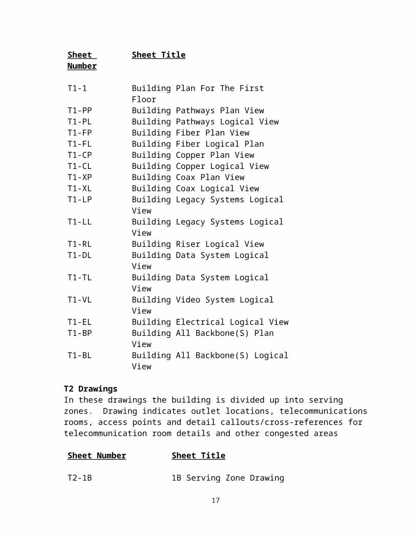
T1 DrawingsT1 drawings shall include layouts of the complete building per floor. The drawing indicates location of serving zones, communication equipment rooms, access points, pathways and other systems that need to be viewed from the complete building perspective.
Sheet Number Sheet Title
T1-1 Building Plan For The First FloorT1-PP Building Pathways Plan ViewT1-PL Building Pathways Logical ViewT1-FP Building Fiber Plan ViewT1-FL Building Fiber Logical PlanT1-CP Building Copper Plan ViewT1-CL Building Copper Logical ViewT1-XP Building Coax Plan ViewT1-XL Building Coax Logical ViewT1-LP Building Legacy Systems Logical ViewT1-LL Building Legacy Systems Logical ViewT1-RL Building Riser Logical ViewT1-DL Building Data System Logical ViewT1-TL Building Data System Logical ViewT1-VL Building Video System Logical ViewT1-EL Building Electrical Logical ViewT1-BP Building All Backbone(S) Plan ViewT1-BL Building All Backbone(S) Logical View
T2 DrawingsIn these drawings the building is divided up into serving zones. Drawing indicates outlet locations, telecommunications rooms, access points and detail callouts/cross-references for telecommunication room details and other congested areas
Sheet Number Sheet Title
T2-1B 1B Serving Zone DrawingT2-CL Copper Logical Drawing by Riser
11

T2-PL Pathway Logical Drawing by Riser
T3 DrawingsT3 drawings shall provide a detailed look at telecommunications rooms. Drawings indicate technology layout (equipment racks, ladder rack, MEP layout, equipment rack elevations, and backboard elevations. These could also be an enlargement of congested areas of T1 and T2 drawings.
Sheet Number Sheet Title
T3-1B Telecommunications Equipment Room 1BT3-APB Access Points for “B” Riser
T4 DrawingsT4 drawings shall include detailed drawings of typical symbols such as faceplate labeling, faceplate types, installation procedures, etc.
Sheet Number Sheet Title
T4-SYM Sample Symbols Drawing
MISC. DrawingsAdditional drawings that may be used in conjunction with the other “T” drawings listed.
Sheet Number Sheet Title
T5-1 Schedules/spreadsheets to show cutover information and cable plant management
T1-RP Building Reference Plan/Same Concept as Site Plan
TS-1 On drawing Specifications (Specs. Pasted to a drawing sheet)
T-COVER Drawing set cover page listing all drawings in the “T” set
1.9.3 Required Specifications
12

The telecommunications section of the "specifications" manual shall be numbered separately and distinctly from other sections. The new 2004 CSI format has been approved and is required.
1.10 Low Voltage Designer and Contractor Qualifications
1.10.1 Telecommunications Designer
A. It is required that the telecommunications design firm of record shall have a BICSI Registered Communications Distribution Designer (RCDD) on staff.
B. All drawings and specifications shall be reviewed by the RCDD employed by the design firm and carry that RCDD registration stamp on all drawings and specifications.
1.10.2 Telecommunications Contractor
A. The telecommunications contractor shall be licensed in the State of Georgia as a Telecommunications Class or Unrestricted Class Low-Voltage Contractor (LVL). GTA, GSFIC and the Using Agency shall be responsible for notifying the Secretary of State of any person acting as an LVLTC without a license.
Note: An Electrical Contractors license does not supersede a Low Voltage License (LVL) and any person engaged in this shall be committing an unlawful act. When an Electrical Contractor company performs telecommunications work they must also hold an active Georgia Low Voltage License to legally perform the work. Subcontracting work by an Electrical Contractor who does not hold an active LVL to a Low Voltage Licensed Contractor is not allowed. The prime LVLTC contractor to the General Contractor must be the license holder. The entire installation must be performed by the LVLTC, no sharing of work between Electrical Contractors and LVLTC’s is allowed. (i.e. LVLTC must place cable, terminate and test, etc.)
B. The Low-Voltage Licensed Telecommunications Contractor (LVLTC) shall be based in the State of Georgia.
C. The installation of the #a shall be performed by a LVLTC company that is currently a Manufacturer’s Certified Structured Cabling System installer in good standing.
D. The LVLTC installation company shall have an RCDD on staff performing the role of Project Manager and be available for consultation and to attend project meetings.
E. A full-time LVLTC manager shall be on site whenever work is being performed or workers are present.
References
13

The state may, with full cooperation of the LVLTC, visit installations to observe equipment operations and consult with references. Specified visits and discussion shall be arranged through the LVLTC; however, the LVLTC personnel shall not be present during discussions with references. The LVLTC must provide a minimum of three (3) reference accounts at which similar work, both in scope and design, have been completed by the LVLTC within the last two (2) years.
1.10.3 Change Approvals
The on-site manager will notify the GTA RCDD, the telecommunications system designer and the Agency’s Inspector of all change requests and inspections. Final approval for change requests must be obtained in writing from GTA and the Agency Inspector before commencement of work.
1.10.4 Required Inspections
Scheduling and coordinating the three required site inspections between the LVLTC, the GTA RCDD and the Agency’s Inspector is critical. The Architect of record, the General Contractor and the Using Agency are required to initiate these inspections. The three required site inspections generally fall into; 1.)The completed installation of infrastructure conduits, pathways and spaces. 2.) Cabling placement and termination. 3.) Final inspection with review of required documentation. Any number of additional inspections as needed may be requested by either involved party.
1.10.5 Prime Vendor/Contractor
In the event multiple LVLTC Vendors submit a joint response to the RFQ, a single Vendor shall be identified as the Prime Vendor. Prime Vendor responsibilities shall include performing overall project administration and serving as a focal point for the state to coordinate and monitor plans, schedules status information and administer changes required. The Prime Vendor shall remain responsible for performing tasks associated with installation and implementation of the entire telecommunications project.
1.11 Overall Quality Assurance
1. The design shall be in accordance with the most recent BISCI Telecommunications Distributions Methods Manual, the most recent GTDM and all ANSI/TIA/EIA standards.
2. The LVLTC shall install work in accordance with the BICSI Cabling Installation Manual.
3. Periodic inspections by the GTA RCDD and the Agency representative (see 1.10.4) shall be part of the quality assurance.
14

1.12 Submittals and Documents Review
1. Before installation of any cable or support equipment the LVLTC shall submit shop drawings and product data to the GTA/RCDD and designer for review and approval.
2. The LVLTC shall indicate installation details, cable routing, system configuration, and work area outlet numbering on all drawings.
3. The LVLTC shall submit all appropriate product data for each component to be supplied.
4. The LVLTC shall submit the manufacturer's installation instructions for each component to be supplied.
1.13 Project Record Documents
1. The designer shall require in the specifications that the LVLTC submit three copies of a complete, bound, project record manual consisting of the following:
Product cut sheets for all products supplied Test reports for horizontal cabling Test reports for backbone cabling Manufacturer’s warranties Scaled, as-built drawings
One set of which must be delivered by the Architect to the GTA/RCDD prior to the final inspection.
2. As-built drawings shall accurately record location of service entrance conduit, termination backboards, outlet boxes, cable raceways, cable trays, pull boxes, and equipment racks delivered electronically using AutoCAD and paper prints. PDF files are not allowed.
3. The LVLTC shall prepare (at a minimum) 11” x 17" as-built serving zone drawings for each Telecommunications Room (TR); all serving zone drawings also shall be posted in the Equipment Room (ER). The drawings shall be laminated, framed and secured to the wall in each ER and TR.
1.14 Post Construction Warranties and Other Requirements
The LVLTC shall furnish a manufacturer’s warranty of the structured cabling system that includes products, performance, application assurance and workmanship for a minimum of 25 years from the date of acceptance by the state.
The LVLTC shall pass along to the Agency Owner any additional or extended warranties offered by the manufacturers, at no additional costs to the Agency.
15

The LVLTC of record shall provide, at a minimum, a one year performance of work warranty on all installations.
1.15 The Georgia Technology Authority (GTA)
The designer is reminded that the State of Georgia is the owner of all property and completed projects.
The Georgia Technology Authority (GTA) is responsible for approving/accepting all telecommunications systems in all state owned or leased buildings.
GTA is represented by regional GTA Registered Communications Distribution Designers (GTA RCDD) during the design and construction of capital facilities for the state. The RCDD will assist the design team and the other trade representatives throughout the design and construction process.
GTA reserves the right to send its RCDD as representative to attend construction
meetings.
The GTA RCDD shall help resolve issues concerning the telecommunications infrastructure during design and construction.
1.16 Role of the GTA Registered Communications Distribution Designer
The architect and the designer of the telecommunications system shall be provided assistance by the GTA Registered Communications Distribution Designer (RCDD). The GTA RCDD shall assist by advising and assisting state agencies with planning, designing and inspection of the structured cabling systems and associated infrastructure installed statewide. This includes review of pre-design, schematic design and construction design stages of each project. Elements for review include drawings, plan sets and technical specifications for telecommunications. All reviews shall be submitted in writing using the approved GSFIC/GTA review form.
GTA reserves the right to send its GTA RCDD as a representative to inspect any job site(s) during construction to ensure compliance with this telecommunications manual and all associated telecommunications codes and standards at any time.
The GTA RCDD shall be included in all phases of the project from the first preliminary meeting to the final walk-through, including each architectural, engineering, and construction phase as found in the published Statewide Construction Manual, Administrative Procedures for Telecommunications.
Providing input to the design and implementation of the telecommunications infrastructure.
16

Providing final approval of the details of the specifications for the Information Transport Systems cabling requirements at each phase and milestone of the project.
Serving as a single point of contact for coordinating and provisioning of telecommunications services of new construction, renovations and additions to each facility and for all other associated tasks required for service and support provided through GTA.
Developing, promulgating and maintaining guidelines, standards and this manual for the construction and management of cabling system technology in the state.
Assists with developing statewide standards for the efficient exchange of electronic information and technology related to infrastructure, cabling and support systems with the public and private sectors in the State.
Assists with the formulation of specifications for telecommunications systems to transport voice, data and video signals. Maintains approved lists of products and devices to be used.
Assists with the analysis and approval of telecommunications facilities and other communications equipment and goods.
Assists with the review and approval of agreements and contracts for communications distribution design and construction services prior to execution between state agencies and other public or private agencies.
Maintains and administers an electronic database system to monitor and evaluate executed cabling contracts.
Review all requests for waivers or deviations from this manual or other standard. No waivers or deviations from codes will be allowed. All state approved safety regulations must be adhered to and the GTA/RCDD will work closely with code officials, the Secretary of State and the State Fire Marshall’s Office to assure compliance.
1.17 Role of the State Agency
The architect and the designer of the telecommunications system shall be aware of the role of the State Agency. The State Agency shall assist in the following roles:
To establish a budget for telecommunications and to provide financial support for the telecommunications system(s).
Ensure that a virtual team for the design and implementation of telecommunications is established and shall include the following participants at a minimum: 1) the Architect,
17

2) the GTA RCDD, 3) the Agencies IT representative and 4) the Agencies Project Manager and other participants as necessary.
Assure compliance with state policies, applicable codes, industry standards and this Georgia Telecommunications Design Manual.
Ensure that only LVLTC professionals licensed to operate within the State of Georgia are allowed to install telecommunications cabling and support infrastructure.
1.18 Requirements for Information Transport Systems
The requirements of this manual address various aspects of providing and managing the telecommunications cabling infrastructure needed for effective voice, data, and video telecommunications services in Georgia facilities.
This infrastructure is a critical resource needed to conduct the business of the State of Georgia. These requirements are discussed using the telecommunications and networking reference layers of the Open Systems Interconnect - Seven Layer Model, also called the OSI model.
The physical OSI layer addresses signal transmission media, connectors, and related devices. The State of Georgia bases its physical layer cabling standards on the current release of ANSI/TIA/EIA 526, 568, 569, 606 standards and any subsequent TSBs and amendments. 1.18.1 Compliance with Standards Based Designs
Agencies shall install standards-based structured cabling systems for telecommunications.
Agencies shall employ standards-based designs, topologies, and components, maintain distance limitations, installation methods, cable testing and administration whether for cabling in new construction for cabling plant additions or modifications; or for building renovations and additions. Also, agencies must require standards-based installations in leased spaces. All minimum requirements or mandatory criteria addressed in ANSI/TIA/EIA 568 shall be met unless exceptions are noted in this manual.
1.18.2 Category 6 Cabling
ANSI/TIA/EIA 568 allows Category 3 cabling. The State of Georgia does not support any new installations of Category 3 horizontal cable. On all new installations, at least a Category 6 structured cabling system shall be installed.
With the advent of VoIP and the universal migration to this technology by almost all using agencies, the State of Georgia has adopted the use of Category 6. All horizontal cables shall be terminated into patch panels for distributed use.
18

1.18.3 Provisioning
Agencies shall plan and budget for installation of manufacturer’s performance warranted structured Category 6 cabling systems when installing new or replacement telecommunications cabling.
Agencies are encouraged to install cable management systems that have a software-based system requiring connectivity components, so connections can be tracked in real time.
In a typical office, a minimum of two Work Area Outlets shall be provided on opposing walls. Each Work Area Outlet shall include, at a minimum, two Category 6 connections. In some cases fiber to the desktop and video cabling may also be required.
1.18.4 Optical fibers
Optical fiber cable used in horizontal cabling shall be 50/125 micron. Optical fiber in the backbone may be 8.3/125 single mode or 50/125 micron multi-mode. Optical fiber 62.5/125 micron multi-mode may be used if approved by waiver in writing by the GTA RCDD. Backbone fiber installed shall be a minimum of 24 strands (12pair) multimode and 24 strands (12pair) single mode. Smaller sizes may be used only if approved by waiver in writing by the GTA RCDD.
1.18.5 Pathways
Agencies are expected to provide appropriate pathways and spaces for telecommunications cabling and equipment by implementing the minimum requirements of ANSI/TIA/EIA 569-A, Commercial Building Telecommunications Pathways and Spaces and all related addenda.
Pathway and room size requirements must be adjusted for higher and lower densities of telecommunications work area outlets and for additional equipment over and above what is expected in the average situation.
Installation of conduits, cable trays and duct banks require other licensed contractors (i.e., electrical) to perform those portions of projects under the appropriate CSI divisions.
The GTA/RCDD shall be contacted to review and approve plans for these spaces as early as possible in the planning process.
1.18.6 Grounding and Bonding
Agencies shall follow grounding and bonding requirements specified in ANSI/TIA/EIA 607, Commercial Building Grounding and Bonding requirements for Telecommunications.
1.18.7 Ethernet
19

Agencies changing their LAN services shall migrate to a minimum of IEEE 802.3 Fast Ethernet (100 Mbps Switched Ethernet) or to a higher bandwidth Ethernet service 802.3, full duplex Fast Ethernet, 802.3ab Gigabit Ethernet over copper, or 802.3z Gigabit Ethernet over fiber). Agencies shall use an access method within the above specified migration path depending on their particular bandwidth needs. It is not necessary for agencies to know the details in the IEEE 802.3 standard as it relates to cabling systems.
1.18.8 Administration
All agencies shall employ methods for administering telecommunications infrastructure that are compliant with ANSI/TIA/EIA 606, Administration Standard for the Telecommunications Infrastructure of Commercial Buildings.
1.19 Georgia Technology Authority - Managed Cabling Services
GTA offers Managed Cabling Services to all state agencies and extensions (counties and municipalities) of state government. When GTA provides these services the GTDM shall be the governing document utilized for all Information Transport System (ITS) installations. To obtain these services contact your GTA Account Management representative.
GTA reserves the right to provide ITS installations for all agencies or extensions thereof on any capitol project (new construction, renovation, leased space or other) upon request.
Telecommunications Spaces
2.0 Common Requirements for Telecommunications Spaces
2.0.1 DefinitionTelecommunications Spaces (TS) are spaces that house telecommunications/computer equipment and include: Equipment Rooms (ER), Telecommunications Rooms (TR) and Service Entrance Facilities (SEF).
2.0.2 Architectural Requirements
A. Size Provide at a minimum, 0.75 ft2 of Equipment Room floor space for every 100 ft2 of work area floor space. The minimum size shall be 150 ft2. If it is expected that the density of work areas will be higher, then the size shall be increased accordingly.The table below indicates the minimum floor space required for standard office buildings:
Gross Floor Space Served
Floor space dimensions
(ft2) (ft)100,000 12 x 6.5200,000 12 x 9.0
20

400,000 12 x 13.0500,000 12 x 15.5600,000 12 x 18.5800,000 12 x 22.5
1,000,000 12 x 27.5
For special-use buildings (e.g., schools, hospitals and laboratories) or non-traditional office space, the Equipment Room floor space shall be based upon the known number of work areas and not on usable floor space as follows:
Work Areas Served Floor Space Required
(ft2)Up to 100 150101 to 400 400401 to 800 800801 to1,200 1,200
The minimum height from the finished floor to the finished ceiling shall be 10'-0”.
In multi-tenant buildings a decision shall be made whether the equipment will be located in a common Equipment Room or in the tenant space. The size of the space shall be increased to accommodate multiplicity of equipment if the room is shared.
B. LocationThe TS shall be located away from sources of electromagnetic interference: electrical power supply transformers, electric motors and generators, x-ray equipment, magnetometers, radio or radar transmitters and induction sealing devices. Locations that limit future expansion such as those near elevators and the building core shall be avoided. Accessibility for the delivery of large equipment shall be provided.
All telecommunication spaces shall be rectangular in shape. Designating rooms with curved walls or odd shapes for Telecommunication rooms is not allowed.
Telecommunication spaces shall not be located so that building columns take up floor space within the room.
Telecommunication spaces shall not be located under restrooms, laundry rooms, kitchens, janitorial sinks or any other common building water service.
Telecommunication spaces shall not have HVAC drain systems or in floor drains
within the space.
C. Finishes
21

False ceilings shall not be provided in any TS. Floors shall be covered with light colored, anti-static vinyl tile. Walls and ceiling shall be treated (painted) to reduce dust. Finishes shall be light (white) in color to enhance lighting.
D. DoorsThe entrance door shall be a minimum of 36 inches wide and 80 inches high, fitted with a lock and shall open into and be accessible from inside the building. If a double door is provided there shall not be a permanent center post. Entrance doors shall not open to the exterior of a facility.
E. Fire ExtinguishersPortable fire extinguishers shall be provided and maintained per applicable codes.
F. Room IdentifiersFor installation purposes, the space shall be identified as: “T xy” – where “T” represents the room type: Equipment Room, Telecommunications Room or Service Entrance Facility, “x” indicates the floor of the building occupied by the TS, and “y” is an alpha character uniquely identifying a TS on floor “x”. Example: “Telecommunications Room 3B” for the second TR on the third floor of the building.
2.0.3 Structural Requirements
A. Floor Loading
Minimum distributed load rating: 100 lbf/ft2
Minimum concentrated load rating: 2,000 lbf.
B. Floor Sleeves and Slots
There shall be a minimum of four 4” sleeves installed on the inside wall at a height that will be above the finished hallway ceiling and extending into the hallway to the cable tray for horizontal pathways.
There shall be a minimum of four 4” sleeves installed in the floor and in the ceiling for riser cabling to telecommunications spaces that are located on the floors above or below the equipment room.
The Structural Engineer shall approve the quantity, location and configuration of floor sleeves and slots.
Firestopping shall be applied for all sleeve penetrations on the outside and inside of the sleeve. Slots will require pillows or other approved system of Firestop.
2.0.4 Mechanical Requirements
A. HVAC
22
Temperature and humidity shall be controlled to provide continuous operating ranges of 64°F to 75°F with 30% to 55% relative humidity. The ambient room temperature and humidity shall be measured at a distance of 5ft AFF, after the equipment is in operation, at any point along a telecommunications equipment aisle. HVAC systems shall be provided properly sized from load factors derived by the electronic manufacturers’ requirements. HVAC systems shall not be shared with ergonomic spaces.
Heat load requirements shall be based upon actual equipment to be installed plus a growth factor. Where the actual equipment to be installed is unknown, the following heat dissipation values shall be used as a guideline for sizing the HVAC equipment:
ER Room Size
Heat Dissipation
8' x 16' 6,000 BTU/Hr. 8' x 20' 7,500 BTU/Hr.10' x 24' 13,000 BTU/Hr.14' x 24' 16,000 BTU/Hr.18' x 28' 25,000 BTU/Hr.20' x 32' 30,000 BTU/Hr.20' x 36' 34,000 BTU/Hr.24' x 40' 45,000 BTU/Hr.
The following table indicates the maximum allowable contaminants in the equipment room. If concentrations are present in quantities greater than indicated, then vapor barriers or absolute filters shall be provided.
Contaminant Concentration
Chlorine 0.01 ppmDust 100.0 µg/m3/ 24 hours
Hydrocarbons 4.0 µg/m3/ 24 hoursHydrogen Sulfide 0.05 ppmNitrogen Oxides 0.1 ppmSulfur Dioxide 0.3 ppm
If batteries are used within the equipment room, ventilation shall be provided per manufacturer’s requirements.
Potential vibration problems shall be considered. The TS shall be free of water or drain pipes.
B. Fire SuppressionIf sprinklers are required by fire code, the heads shall be protected with wire cages to prevent accidental operation. Drainage troughs shall be placed under the sprinkler pipes to
23

prevent leakage onto the equipment within the room. Consideration shall be given to the installation of alternate fire-suppression systems or a dry pipe system.
2.0.5 Electrical Requirements
A. Grounding & BondingThe grounding system for telecommunications shall comply with ANSI/J-STD-607 A, TIA-942, and IEEE STD 1100.
The Telecommunications Main Grounding Busbar (TMGB) shall be ¼”x 4”x 12” and the Telecommunications Grounding Busbar (TGB) shall be ¼” x 2” x 12”. All grounding busbars shall be made of tin plated copper. All metallic conduits, cable trays, racks, cabinets, etc. in the TS shall be bonded with minimum #6 AWG green insulated copper conductor to the TMGB or TGB. All grounding lugs should be 2 hole compression-type copper.
B. PowerAll equipment in the space shall be connected to an Uninterruptible Power Supply (UPS). The UPS can be centralized (a UPS that serves the entire facility or the entire TS), or a rack mounted UPS can be installed in each equipment rack.
Each equipment rack that will have active telecommunications equipment installed shall be provided with a surge-protected multiple-outlet strip.
When a central UPS system is used, the power strip shall be hard wired to a dedicated 20Amp UPS circuit in a junction box attached to the structure above the equipment rack. When a UPS is installed in each equipment rack, the power strip shall be connected to the UPS. A dedicated twist-lock receptacle attached to the structure above the equipment rack shall be provided to serve the UPS. When a raised floor is used, the power junction box shall be installed under the raised floor. Convenience duplex electrical receptacles shall be placed at 18in AFF along the wall, spaced every 6ft.
C. Lighting The average maintained illumination measured 3 feet AFF in the space shall be 50
foot-candles. The luminaries shall be mounted at minimum 8 feet 6 inches AFF. At least one lighting fixture within the room shall be connected to the emergency
lighting circuit for the facility or provided with emergency battery ballast.
2.0.6 Build-out Requirements
A. Plywood BackboardsProducts:
24

A minimum of two walls in each space shall be covered with rigidly fixed, ¾”, A-C grade, void free plywood, capable of supporting wall mounted telecommunications devices.
Execution:
Plywood backboards shall be installed 6” above the finished floor to 8’6” AFF.
Plywood backboard shall be mounted with a minimum of 3/8” toggle bolts and 2” fender washer on each corner and 4’ on center as required.
All six sides of each backboard shall be painted with two coats of white fire retardant paint prior to installation. Fire retardant additives may be used in paint.
B. Equipment Racks
Products:
Equipment racks shall meet the following specifications: Manufactured to house 19” wide equipment and be 84” in height Hole patterns conforming to EIA-310-D Capable of supporting a maximum load of 750 Lbs. Wall mounted equipment racks may be used with written approval from the
GTA/RCDD Finished with flat black powder-coat paint
Execution: Equipment racks shall be installed per the manufacturer’s written
instructions. Racks shall be assembled such that mounting rails are perpendicular to the
base. Secured to the ladder rack Secured to the floor using appropriate anchors. Minimum 3’-0” of clearance shall be required in the front, back and one side
of the racking system, measured from the base of the rack footing closest to the wall.
Bonded to ground as required by the NEC, ANSI/J-STD-607 A and TIA-942. All racks shall be labeled in accordance with ANSI/TIA/EIA 606A.
C. Cable Management for Equipment RacksProducts: All vertical and horizontal cable management panels shall be black.
25

Vertical cable management panels shall have front and rear channels, minimum 6” wide and shall be equipped with removable front and back covers.
Horizontal cable management panels shall have front and rear channels and a minimum height of 2 rack units. When patch panels are provided with rear bars or other strain relief support, the rear channels are not required. When angled patch panels are installed, horizontal cable managers are not required.
Execution: A vertical cable manager shall be installed between each equipment rack in a
row and at each end of the row. A horizontal cable manager shall be installed at the top of each rack and
above and below each patch panel.
D. Overhead Ladder Racking (Cable Runway)Products: The overhead racking shall be ladder type, with tubular side bars nominally
3/8” thick by 1 ½” high (minimum) and ½” x 1” welded rungs spaced minimum 9” on center.
The ladder racking shall be sized by amount and type of horizontal cables according to NEC 392 and TIA 569B.
Finish shall be powder coated, black. Include connecting and all other support hardware for a complete installation
including but not limited to equipment rack to runway mounting plates, wall angle support brackets, butt splice swivels, junction splice connections and grounding kits.
Execution: Ladder type racking shall be installed at minimum 84” AFF around the
perimeter of the room and connected to the top of all equipment racks. Vertical cable racking shall be installed on the walls above and/or below the
sleeves. Cable ladder racking shall be supported at minimum three foot intervals from
the ceiling, walls, floor and/or rack/cabinet and per manufacturer’s written instructions.
Cable radius drops shall be attached to the ladder rack stringers or rungs to facilitate cable entering and exiting the cable tray while protecting the physical properties of the cable.
Cables shall be secured to the cable racking using Velcro cable wraps to arrange cable in logical bundles.
Ladder rack shall be bonded as required by the NEC and J-STD-607-A, TIA-942, and IEEE Std 1100.
E. Bonding BusbarProduct:Telecommunications Grounding Busbar (TGB) assembly shall meet the following specifications:
26

copper bar, minimum 1/4” x 2” x 12” type 304 stainless steel brackets, 1/8” thick type 304 stainless steel fasteners 2” insulated standoffs, UL 94 VO
The Telecommunications Main Grounding Busbar (TMGB) shall be ¼”x 4”x 12” . All grounding busbars shall be made of tin plated copper.
Equipment rack/cabinet ground bar shall meet the following specification: copper bar, minimum 3/16” x 3/4” x 18 5/16” for attachment to 19” mounting
rails of equipment racks and cabinets
Hardware and lugs shall meet the following specifications: lugs shall be copper alloy construction terminals shall be solderless compression type, copper long-barrel NEMA two
hole bolts shall be silicone bronze construction bonding connectors and clamps shall be mechanical type made of silicon bronze
Execution:One TGB shall be installed in each ER/TR and shall be bonded to the Telecommunications Bonding Backbone (TBB) per ANSI/J-STD-607 A. Communication grounding and bonding shall be in accordance with applicable codes and regulations. The requirements of ANSI//TIA/EIA-607and the NEC shall be followed throughout the entire cabling system.
2.1 Service Entrance Facility Room (SEF)
2.1.1 Definitions
The Telecommunications Service Entrance Facilities (SEF) is where all telecommunications (voice, data and video) service cabling enters the building. This room provides space for the placement and termination of cable protectors on entrance cables and may contain network interface devices. It is acceptable for the SEF room and the ER to be one and the same room but may be separate rooms in larger (more than 100,000 sq ft) facilities. In general a dedicated service entrance facility room does not require environmental conditioning since electronic equipment is typically housed in a separate ER. When both rooms are combined design specifications for the ER shall be followed and the size of the SEF/ER shall be increased accordingly to accommodate for the required equipment of both rooms.
2.1.2 Architectural Requirements
A. Size
27

Multiple/diverse entrances may be required where security, redundant service, or other special needs exist. Without exception the SEF room shall always be located in a dry area, not subject to flooding, on the ground floor and on an exterior wall. To comply with NEC the SER must be near to the electrical service entrance room but not within the same space. Equipment not related to the support of the SEF room (e.g., piping, ductwork, pneumatic tubing, etc.) shall not be installed in, enter or pass through the room.
Also See Common Requirements 2.0.2-A
B. Location
The SEF room shall be sized to meet the known requirements of the specific Building Entrance Terminals (BET)/lightning protection (i.e. carbon, gas, electronic) to be installed and to provide for termination, splicing or transition to building cabling i.e., riser or plenum rated cables. Sizing shall include projected future and present requirements.
Also See Common Requirements 2.0.2-B
C. Finishes
See Common Requirements 2.0.2-C
D. Doors
See Common Requirements 2.0.2-D
2.1.3 Structural Requirements
A. Floor Loading See Common Requirements 2.0.3-A
B. Floor Sleeves and Slots See Common Requirements 2.0.3-B
2.1.4 Mechanical Requirements
A. HVAC
Equipment not related to the support of the SEF room (e.g., piping, ductwork, pneumatic tubing, etc.) shall not be installed in, enter or pass through the room.
Also See Common Requirements 2.0.4-A
28

B. Fire Suppression
See Common Requirements 2.0.4-B
2.1.5 Electrical Requirements
A. Grounding and Bonding
See Common Requirements
B. Power
See Common Requirements
C. Lighting
See Common Requirements
2.1.6 Build-out Requirements
A. Plywood Backboard Products
See Common Requirements Execution
The installed plywood shall be capable of supporting Building Entrance Terminals (BETs) and other wall mounted telecommunications entrance devices.
B. Overhead Ladder Racking Products
See Common Requirements Execution
See Common Requirements
C. Bonding Busbar Products
See Common Requirements Execution
A TMGB shall be installed at an accessible and convenient location in each Entrance Facility.
2.2 Equipment Rooms (ER)
2.2.1 Definition
29

The Equipment Room (ER) houses the telecommunications and/or computer equipment that support a building or a campus. Each campus shall have a minimum of one ER. Each building that is not part of a campus shall have a minimum of one ER.The ER may serve the functions of a Telecommunications Room for the surrounding section of the building, or may contain the Service Entrance Facility (SEF) for the building. In these cases, the ER shall also comply with the requirements for TR and/or SEF.
2.2.2 Architectural RequirementsA. Size
See Common Requirements 2.02-A
B. Location
Also See Common Requirements 2.0.2-B If the ER and SEF rooms are combined then the ER room shall be located within 50
feet of the outside wall on the ground floor and must comply with the most current NEC.
The ER shall not be located below water level unless preventative measures against water infiltration are provided.
The ER shall have easy access to the backbone pathways for cabling to SEF, and TRs.
C. Finishes
See Common Requirements.False ceiling shall not be provided in the ER. Floors shall be covered with light colored, anti-static vinyl tile. Walls and ceiling shall be painted. Finishes shall be light in color to enhance lighting.
D. Doors
See Common Requirements.
E. Fire ExtinguishersSee Common Requirements.
F. Access FloorsAccess floor shall be provided if the ER is larger than 12'x20' or when it is required by the tenant. The access floor shall be minimum 6" high and shall be rated for minimum 100lbf/ft2
distributed loading and 2,000lbf concentrated loading. An ADA compliant ramp shall be provided to access the raised floor area. Under floor cable tray will be required to support all cabling.
30
G. Room Identifier
The ER shall be identified as: "Equipment Room fA" – where "f" indicates the floor of the building occupied by the ER and "A" is an alpha character uniquely identifying a telecommunications space (ER, TR or SEF) on floor "f".
2.2.3 Structural Requirements
A. Floor Loading See Common Requirements 2.0.3-A.
B. Floor Sleeves and Slots See Common Requirements 2.0.3-B
2.2.4 Mechanical Requirements
A. HVAC
See Common Requirements 2.0.4-A
B. Fire Suppression
See Common Requirements 2.0.4-B
2.2.5 Electrical Requirements
A. Grounding & Bonding See Common Requirements.
B. Power See Common Requirements.
C. LightingSee Common Requirements.
2.2.6 Build-out Requirements
A. Plywood BackboardSee Common Requirements.
B. Equipment CabinetsProducts:Equipment cabinets where required shall be used to house active telecommunications equipment. The dimensions and design of the cabinet shall be selected based on the requirements of the equipment to be installed in the cabinet.
31

Execution:Equipment cabinets shall be installed by the manufacturer’s requirements for all locations. The use of rolling cabinets is not permitted unless written authorization is obtained from the GTA/RCDD.
C. Equipment RacksSee Common Requirements.
D. Horizontal Cable ManagementAll systems installed shall require the installation of a horizontal cable manager sized to the application (1 RU, 2RU, etc) above and below each flat patch panel installed. Where angled patch panels are specified, cable managers are only used where required.
E. Vertical Cable ManagementEach installed equipment rack installed shall have a vertical cable manager on each side. The vertical cable manager shall be a minimum of six inches wide and have a double depth channel for front and rear management.
F. Cable TraySee Common Requirements.
G. Bonding BusbarSee Common Requirements.
H. Overhead Ladder RackingSee Common Requirements.
I. Under Raised Floor Cable TrayUnder raised floor cable tray shall meet the following specifications:Products: shall consist of continuous, rigid, welded steel wire mesh minimum 2 inches deep minimum 12 inches wide include connecting and all other support hardware for a complete installation
including but not limited to supports, splices and grounding kitsExecution: Mesh type cable tray shall be installed per manufacturer’s written
instructions, using supports mounted directly to the floor or to the raised floor posts.
Fittings shall be field fabricated from straight sections, per manufacturer’s instructions. Cable tray wires shall be cut with side-action bolt cutters with offset head.
32

J. Telecommunications Grounding & BondingTelecommunications Grounding Busbar (TGB) assembly shall meet the following specifications:
Products: copper bar, minimum 1/4” x 4” x 13 1/2” type 304 stainless steel brackets, 1/8” thick type 304 stainless steel fasteners 2” insulated standoffs, UL 94 VO
The Telecommunications Main Grounding Busbar (TMGB) shall be ¼”x 4”x 12” . All grounding busbars shall be made of tin plated copper.
Equipment rack/cabinet ground bar shall meet the following specifications: copper bar, minimum 3/16” x 3/4” x 18 5/16” for attachment to 19” mounting
rails of equipment racks and cabinets
Hardware and lugs shall meet the following specifications: lugs shall be copper alloy construction terminals shall be solderless compression type, copper long-barrel NEMA two
hole bolts shall be silicone bronze construction bonding connectors and clamps shall be mechanical type made of silicon bronze
Execution:One TGB shall be installed in each ER and shall be bonded to the Telecommunications Bonding Backbone (TBB) per ANSI/J-STD-607 A.
2.3 Telecommunications Rooms
2.3.1 Definition
The Telecommunications Room (TR) on each floor is the recognized location of the common access point for backbone and horizontal pathways only and shall never be used for storage of any kind. (i.e. books, furniture, A/C filters, light Bulbs, etc…) TR space is dedicated to the telecommunications function and related support facilities. Equipment not related to the support of the TR (e.g., piping, ductwork, pneumatic tubing, etc.) shall not be installed, pass through or enter the TR.
TRs must be able to contain telecommunications equipment, cable terminations and associated cross-connect cabling. Telecommunication rooms must have the space and environmental facilities required by the electronic equipment used in today's voice/ data networks, including hubs, switches, terminal concentrators, backbone multiplexing systems, optical fiber patch panels, horizontal cabling patch panels and other devices.
33

2.3.2 Architectural Requirements
A. SizeAlso, see Common Requirements 2.0.2-A.
There shall be a minimum of one TR per floor. Additional TRs (one for each area up to 10,000 ft2) shall be provided when the floor area to be served from the TR exceeds 10,000 ft2; or the distance of the horizontal distribution to the work area exceeds 250 ft of total cable length.
Each TR shall serve an area that will allow all total horizontal cable lengths to be less than 250 ft from the termination location in the TR to any WAO location.
Based upon one work area per 100 ft2, the TR shall be sized as follows
Serving Area (ft2)
Room Size(ft)
10,000
10 x 12
8,000 10 x 105,000 10 x 8
GTA shall be contacted for review and approval of final dimensions and locations of all Telecommunication Rooms.
Source: ANSI/TIA/EIA-569-Series Commercial Building Standard for Telecommunications Pathways and Spaces
B. Location Also See Common Requirements 2.0.2-B TRs shall have direct access to the hallways or corridors.
C. FinishesSee Common Requirements
D. DoorsSee Common Requirements
2.3.3 Structural RequirementsA. Floor Loading
See Common Requirements 2.0.3-A.
B. Floor Sleeves and SlotsSee Common Requirements
34

2.3.4 Mechanical Requirements
A. HVACSee Common Requirements
B. Fire SuppressionSee Common Requirements
2.3.5 Electrical RequirementsA. Power
See Common Requirements
B. LightingSee Common Requirements
2.3.6 Build-out Requirements
A. Plywood BackboardsSee Common Requirements.
B. Equipment CabinetsProducts:Equipment cabinets where required shall be used to house active telecommunications equipment. The dimensions and design of the cabinet shall be selected based on the requirements of the equipment to be installed in the cabinet.
Execution:Equipment cabinets shall be installed by the manufacturer’s requirements for all locations. The use of rolling cabinets is not permitted unless written authorization is obtained from the GTA/RCDD.
C. Equipment RacksSee Common Requirements.
D. Horizontal Cable ManagementAll systems installed shall require the installation of a horizontal cable manager sized to the application (1 RU, 2RU, etc) above and below each flat patch panel installed. Where angled patch panels are specified cable managers are only used where required.
E. Vertical Cable ManagementEach installed equipment rack installed shall have a vertical cable manager on each side. The vertical cable manager shall be a minimum of six inches wide and have a double depth channel for front and rear management.
F. Cable Tray
35
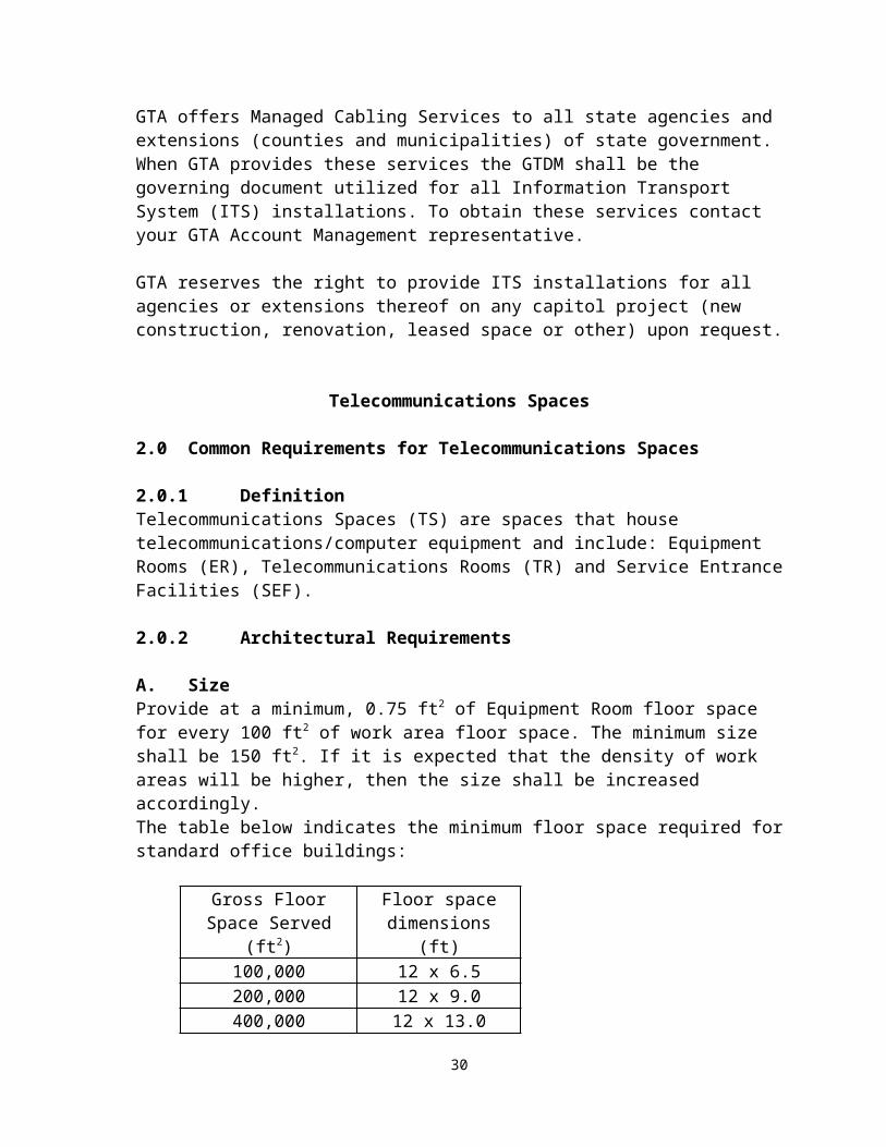
See Common Requirements.
G. Bonding BusbarAlso see Common Requirements
Products:Telecommunications Grounding Busbar (TGB) assembly shall meet the following specifications:
copper bar, minimum 1/4” x 4” x 13 1/2” type 304 stainless steel brackets, 1/8” thick type 304 stainless steel fasteners 2” insulated standoffs, UL 94 VO
The Telecommunications Main Grounding Busbar (TMGB) shall be ¼”x 4”x 12” . All grounding busbars shall be made of tin plated copper.
Equipment rack/cabinet ground bar shall meet the following specifications: copper bar, minimum 3/16” x 3/4” x 18 5/16” for attachment to 19”
mounting rails of equipment racks and cabinets
Hardware and lugs shall meet the following specifications: lugs shall be copper alloy construction terminals shall be solderless compression type, copper long-barrel NEMA
two bolts bolts shall be silicone bronze construction bonding connectors and clamps shall be mechanical type made of silicon
bronze
Execution:One TGB shall be installed in each ER and shall be bonded to the Telecommunications Bonding Backbone (TBB) per ANSI/J-STD-607 A.
H. Overhead Ladder Racking (Cable Runway)See Common Requirements.
I. Under Raised Floor Cable TraySee Common Requirements.
36

PATHWAYS
3.0 Common Requirements
3.1 Definitions: Pathways are the conveyances for distributing the Information Transport System cabling both within and between buildings.
3.0.2 Architectural RequirementLocation
In multi-level structures, the MER and TRs shall be designed in a stacked configuration, i.e., one room above the other. A quantity of four, 4” trade size (103 mm) sleeved holes shall be provided between the rooms. If the MER shall be offset from the TR stack, due to building design limitations, four, 4” trade size (103 mm) conduits shall be provided for the riser system.
The MER shall have vertical 4" ID minimum conduit sleeved holes to the TR above, or if the MER is offset, multiple 4" trade size (103 mm) conduits shall be provided to the TR above. Each TR shall have 4" trade size (103 mm) sleeves between them, or if the TRs are offset, multiple 4" trade size (103 mm) conduits between TRs or ERs shall be provided. An extra minimum 1” trade size (27 mm) metallic sleeve shall be provided for the vertical riser ground system.
The requirements for the vertical riser system shall include the following:
The number of holes or conduits depends on the number of building levels. For multi-level buildings with six (6) floors or less, including the basement or ground floor, the number of sleeves or conduits between a given floor and the one above it shall be six plus a minimum one (1) trade size (27 mm) conduit or sleeve for the vertical ground system. For buildings with seven or more floors, additional four inch sleeves or conduits may be required. Consult with your GTA/RCDD for a determination of the number of additional sleeves or conduit beyond the six.
Requirement for ALL pathways ‘in-slab’:Moisture, in the form of precipitation or condensation, is a problem with ‘in-slab’ pathway systems, especially on or below grade systems. The moisture will, in time, migrate through the jacket of non-OSP cable that is installed in a pathway system, and will degrade the performance of that cable.
For all pathway systems encased ‘in-slab’ that is in contact with earth, OSP cable shall be used.
37

In all ‘in-slab’ systems, the installing contractor shall be responsible for delivering a dry pathway system to the LVLTC. The LVLTC shall notify the Building Owner and GTA RCDD in the event moisture is found.
Conduits must be sealed properly to prevent water, gasses and rodents from egress. Depending upon conditions rubber conduit plugs, duct sealer or water plugs must be used depending upon conditions.
The installation of pathway systems under slab in contact with earth shall be prohibited. Only service entrance feeders shall be permitted to be installed under slab.
Electrical Requirements
All metallic conduit, raceways and cable tray shall be appropriately grounded as specified in the NEC, ANSI/ J-STD 607A and per manufacturer’s specifications.
3.1 Intra-Building (within buildings) Backbone Pathways
3.1.1 Definition Intra-Building Pathways are the conveyances for distributing the backbone media between telecommunication spaces within the building. These conveyances may be conduits, cable trays, and pull-boxes.
3.1.2 Structural Requirements
All pathways shall be attached to the structure as required by the manufacturer, NEC and TIA/EIA 569A. All floor and wall penetrations shall be approved by the structural engineer.
3.1.3 Electrical RequirementsSee Common Requirements
3.1.4 Build-Out Requirements
A. ConduitsProductsElectrical Metallic Tubing (EMT), Intermediate Metallic Conduit (IMC) and Rigid Metal Conduit (RMC) are the only approved conduit types. Flexible metal conduit shall not be used.
Backbone conduit shall be a minimum of 4” trade size (103 mm).
38
Distribution conduits shall be minimum 1” trade size (27 mm) or larger as required to accommodate the proper fill ratio.
Fittings
Rigid galvanized steel fittings shall be fully threaded and shall be of the same material as the respective raceway system.
Compression type fittings shall be used for all conduits 2" trade size (53 mm) and larger. Provide approved abrasion protection bushings on each end of all conduits. Setscrew fittings shall not be used.
Die-cast or pressure cast fittings shall not be used.
Pull Boxes
Pull boxes shall be constructed of not less than 14 gauge, galvanized steel with trim for flush or surface mounting in accordance with the location to be installed. Provide screw-on type covers.
Pull boxes shall be sized per TIA/EIA 569A. Boxes shall be approved for the environmental condition of the installed location.
Innerduct
Three 1¼ inch trade size (35 mm) plenum rated innerducts shall be installed in each 4” trade size (103 mm) conduit that will be utilized for optical fiber backbone cabling.
Execution
All conduit fittings shall be installed per the manufacturer’s instructions.
Factory made sweeps shall be used.
Bend radius shall be no greater than10 times the internal diameter of the conduit insulating bushings shall be installed at all ends of conduits.
Runs exceeding 100 feet or 180 degrees total bends shall be broken with pull boxes. LB or similar conduit fittings shall not be used.
Reverse bends shall not be used without prior approval.
39

Conduit shall be supported as required by the manufacturer and the NEC.
Conduits entering telecommunication spaces shall extend below the finished ceiling or above the floor and shall be supported on the backboard.
Conduits installed for distribution in conjunction with cable tray shall be metallically connected too the cable tray.
Pull boxes shall not be used as bends. Only sweeping bends shall be used.
Immediately after installation, plug the ends of each roughed-in conduit with an approved cap or disc to prevent the entrance of foreign materials and moisture during construction. All conduits shall be clean and dry prior to installation of telecommunication cabling.
Conduit shall be secured within three feet of each pull box or fitting.
Provide a pull string in all conduit and innerducts to facilitate installation of cables. Secure the pull string at both ends.
Conduit fill capacity shall not exceed 40%.
Conduit in concrete floor slabs shall be galvanized rigid steel with concrete tight threaded fittings.
Expansion fittings shall be provided where conduits cross building expansion joints.
Conduits in slabs shall be installed below the reinforcing mesh. Provide a minimum of 1” of concrete around conduit.
Wherever a cluster of four (4) or more exposed conduits rise out of the floor, a neatly formed 4” high concrete envelope with chamfered edges around the cluster of conduits shall be required.
Roof penetrations are generally not recommended. All roof penetrations shall be pre-approved by the Architect and a detailed design provided.
Conduits shall not be located adjacent to steam systems.
Install pull boxes in readily accessible locations. Equipment, piping, and ducts shall not block access to pull boxes.
40
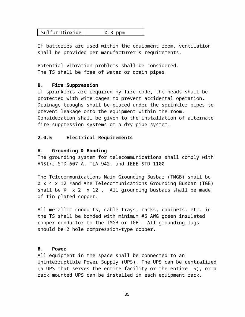
B. Sleeves & Slots
ProductsSleevesMinimum 4” trade size (103 mm) threaded rigid steel conduit with plastic insulating bushing on each end for backbone cabling
ExecutionSleeves
Sleeves shall be pre-approved by the Architect/Structural Engineer.
Cored sleeves shall be attached on each side of the floor / wall using 1.25” support struts and the appropriate conduit clamps to support the sleeves.
Cored sleeves shall extend a minimum of 3” above the finished floor and 3” below the poured concrete structure and supported by the backboard.
Cored holes shall be sealed to prevent smoke and water infiltration between the core hole and the conduit.
Ladder rack shall be installed on the wall below or above all sleeves from the floor to the ceiling above.
Each sleeve and/or slot shall be labeled in accordance with ANSI/ TIA/EIA 606A.
When cable tray is used as an intra-building pathway there shall be a minimum of four 4” trade size (103 mm) sleeves installed at a height that will be above the finished hallway ceiling and extending into the hallway to the cable tray.
There shall be a minimum of four 4” trade size (103 mm) sleeves installed in the floor or ceiling for riser cabling into telecommunications spaces that are located on the floors above or below the equipment room.
All sleeves shall be rigidly installed using appropriate fittings and all penetrations shall be grouted around the sleeve. Sleeves for penetration of walls and floors shall not be filled greater than 50%, shall have 100% spare capacity (spare conduits) and all conduits shall be firestopped per applicable codes.
ProductsSlotsSlots shall be pre-approved by the Architect/Structural Engineer.
41

Minimum size 4” x 10”Minimum two-inch Water Protective dam
Must not obstruct wall termination space
Vertical ladder rack shall be installed on the wall above/below all slots from the floor to the ceiling above.
Provide a minimum two inch water protective dam for all slots installed.
Each sleeve and/or slot shall be labeled in accordance with ANSI/ TIA/EIA 606A.
Execution
Vertical ladder rack shall be installed on the wall above/below all slots from the floor to the ceiling above.
Stand offs shall be installed as necessary to support the required ladder rack. The anchoring system provided shall be suitable for the weight to be supported by the ladder rack. Plywood backing for all ladder rack supports shall be provided.
C. Cable Tray
Products:
The cable tray shall be industry standard, ladder type trays shall consist of two longitudinal members (side rails) with transverse members (rungs) welded to the side rails. Rungs shall be spaced 6”s on center. Wire basket-type tray may also be used.
Each rung must be capable of supporting the maximum cable load, with a safety factor of 1.5 and a 200 pound concentrated load when tested in accordance with NEMA VE-1, section 5.4.
The following table gives dimensions of cable tray by amount of floor space to be served. Cable tray shall be specified and can be 12 to 24” wide of aluminum or steel construction with 3” to 9" rung spacing.
Maximum allowable space to be served by one TR using the cable tray system
Floor Space to Be Served in Square Feet
Cable Tray Dimension
Up to 5,000 12"
42

5,001 to 20,000 18"20,001 to 35,000 * 18"
Shall be aluminum construction including accessories.
Maximum rung spacing shall be 9” on centers.
Minimum cable tray depth shall be 2”.
Rungs shall be welded to side rails.
Standard lengths shall be used.
Minimum radius of horizontal elbows shall be 12” Provide special radius elbows where required for field conditions.
Loading Data:
Useable Tray Width
Load Depth NEMA Depth
Std. Span Lbs/ Ft
Deflection
6” 4”
8” 4”
12” 4” 3” 12A 10’ 81 1.20”
12” 6” 5” 12B 10’ 112
0.59”
18” 4” 3” 12A 10’ 81 1.20”
18” 6” 5” 12B 19’ 112
0.59”
24” 4” 3” 12A 10’ 81 1.20”
24” 6” 5” 12B 10’ 112
0.59”
Execution:
43

Cable trays shall be installed and filled in accordance with ANSI/TIA/EIA -569-A-7, Commercial Building Standard for Telecommunications Pathways and Spaces, Cable Trays and Wire-ways.
The cable tray shall be mounted above the finished ceiling in the main corridor. It is imperative that the cable tray be installed no less than 4” to 8” above the ceiling tile and have no less than a 24" horizontal clearance along one side and 6" above the tray. This will ensure that the cable tray is accessible.
No conduit, pipes, or HVAC duct shall rest on or extend through the cable tray.
Supporting hangers shall be attached along the cable tray sides and not within the cable tray bed.
The cable tray shall "tee off" if required and be run into the ER or TR. If the ER or TR wall is a firewall, the cable tray shall be terminated at the wall and 4" trade size (103 mm) conduit sleeves provided into the room.
The number of 4" trade size (103 mm) conduits penetrating the firewall shall not be less than two for the 12" cable tray and three for the larger cable trays.
Rooms directly adjacent to the TR or ER room may be directly served by home-run conduit, bypassing the cable tray.
Conduit shall be provided as a continuous run perpendicular from the cable tray to the WAO. Each conduit shall be metallically attached to the cable tray. All cable shall be routed in conduit or cable tray for protection.
The cable tray requires ceiling spaces that are accessible. Cable tray shall not be placed above permanent type ceilings or above offices. Sufficient quantities of four-inch EMT conduit shall extend across the inaccessible ceiling to cable trays in the accessible ceiling spaces
EMT shall be installed a minimum of 6 inches above the finished ceiling and a maximum of 2 feet above the finished ceiling and per manufacturer’s requirements and to the top of equipment rack.
The cable tray shall be supported at a minimum of five foot intervals from the ceiling and as the manufacturer recommends.
The cable tray shall be installed to allow access to both sides of the cable tray above the ceiling.
44

Cable radius drops shall be attached to the cable tray stringers or rungs to facilitate cable entering and exiting the tray while protecting the physical properties of the cable.
D. Firestopping Products
Firestopping protection shall meet NFPA 101, Life Safety Code, "Penetrations and Miscellaneous Openings and Fire Barriers" and the NEC "Fire Stopping" regulations and standards.
ExecutionAll penetrations shall be firestopped using a tested system. Thickness, depth and installation of firestop materials shall meet requirements of the material manufacturer and backed by formal ASTM E-814 tests.
All conduits and cable tray penetrations shall be firestopped.
Wherever it is not feasible to use a pillow or caulk, Firestopping putty shall be used.
All vertical penetrations consisting of conduits, sleeves, or chases shall be firestopped at the top and bottom of each penetration on the interior and exterior of the conduit.
All horizontal penetrations consisting of conduits, sleeves or chases shall be firestopped on both sides of each penetration.
Plenum air return ceiling penetrations for conduit shall be sealed with a system appropriate for the substrate and the level of protection required.
During construction, all slots and sleeves must have a firestopping pillow installed. All firestopping pillows must be reinstalled daily during cable installation and at no time shall conduits, slots or sleeves be left unprotected with firestop material.
All sleeves must have a firestopping caulk applied to the outside circumference of the sleeve on each side of the wall penetration and from the top and bottom of a floor penetration.
3.1.5 Administration & Labeling
Products
45

All pathway identification tags shall be a minimum of 3” square surface area, mechanically stamped, legible and permanently affixed.
Acceptable tagging materials are copper, brass or 1/16” thick plastic.
All tags shall be approved by the GTA/RCDD prior to use.
Hand written labels are not permitted.
Execution
Each pathway shall be assigned a unique identifier. This identifier shall be recorded on all as-built drawings. The pathway identifier must also be recorded on the cable and equipment records. The pathway type, pathway fill capacity and current pathway loading shall be recorded for each pathway.
Each pathway shall be labeled within 6” of all endpoints located in all telecommunication spaces. The label shall show, as a minimum, the origin and destination of the pathway. The origin is always the point closest to the Equipment Room. All pathways entering and leaving pull-boxes shall be labeled. Partitioned pathways, such as a conduit with innerduct, shall have a unique identifier assigned to each partition.
All pathways shall be labeled with the appropriate designations per the ANSI/ TIA/EIA 606A standard.
3.2 Inter-Building (between Buildings) Backbone Pathways
Trenching and Excavation
The contractor shall contact the Utilities Protection Center prior to commencement of any trenching activities. College and university campuses may have utilities that the locating service will not locate. It shall be the responsibility of the contractor to contact the Agency and arrange for customer-owned utilities to be located by the customer prior to commencement of any trenching. A letter stating that all utilities have been located shall be obtained by the contractor from the locating service and the Agency.
Any and all costs incurred for damage to any utilities shall be borne by the contractor.
Confined Spaces
The Occupational Safety and Health Administration (OSHA) requirements CFR 1910.268 (0) address telecommunications work performed on underground lines in maintenance holes and un-vented vaults. It is the designer and the contractor’s responsibility to determine if
46

any spaces requiring entry are defined as confined spaces, or as permit-required confined spaces, and to follow all related OSHA procedures.
3.2.1 Definitions
OSP Pathways
Telecommunications Substructure, OSP
The OSP Substructure is the physical pathway used to distribute backbone cabling between buildings, and to bring the entrance cable from the service provider across state property and into the building Entrance Facility. Underground conduit distribution between buildings on a campus shall be used, unless otherwise authorized.
The OSP Substructure must accommodate all low voltage services planned for initial installation, plus a minimum of 25% growth capacity. The minimum size conduit allowed is 4” trade size.
3.2.2 Site Requirements
Underground Distribution
Underground distribution of low voltage services on state property shall consist of appropriately sized conduit duct banks, telecommunications vaults or handholes. Telecommunications services and other low voltage services such as fire alarm, security systems, and CATV distribution shall not share the same underground distribution conduits and vaults as electrical power distribution.
Re-routing of Existing OSP Telecommunications Utilities
Contractor shall notify, in writing, the State Owner and the GTA, RCDD prior to any outage or re-routing of any existing telecommunications cabling. Prior written approval for any outage or re-routing of facilities shall be obtained. The outage shall be scheduled at the convenience of the State.
Provide new pathways for existing telecommunication cables that are currently located in the footprint of the new facility being constructed. Note: Operating Local Exchange Carriers (BellSouth, Windstream, etc.) may require up to six months notice prior to relocation of their existing utilities. There is always a charge for this service relocation.
Contractor Preparatory Work Requirements
Locate and stake each conduit run for its entire length. Start excavation at lowest elevation. Notify the GTA, RCDD of any discrepancies.
47

Protect marks and stations. Coordinate with Owner's Site Representative and other trades before initiating
excavating work,. Furnish schedule of operations to Owner and each trade. Provide and maintain pedestrian and vehicle traffic protection. Examine substrates, areas and conditions, with the installer present, for compliance
with requirements for installation tolerances and other conditions affecting installation.
All underground feeders for utilities shall be located and flagged prior to digging.
Installation shall not proceed until unsatisfactory conditions have been corrected.
Protection Requirements
Provide adequate bracing, shoring, sheathing and other work for the protection of personnel, contract work, excavations, trees, shrubs, existing structures, and surrounding properties.
Slope sides of excavations to comply with local codes and ordinances. Provide, erect, and maintain barricades, warning signs, flags, and lights to provide
protection for work, workmen, public, and property. Plank all walks, pavements, and curbs to be crossed by equipment. Protect adjacent property, existing fences, trees, shrubs, roads, curbs, sidewalks,
maintenance holes, hydrants, and other items Restore, repair, rebuild or replace any such items damaged or destroyed to condition
equal to that existing before such damage occurred. Establish conditions, before starting work, by taking photographs to determine state
to which existing conditions must be restored. Photographs shall be notarized.
Existing Utilities
All service lines, utilities and utility structures which are uncovered or encountered during excavation, shall be protected from damage, and securely supported.
Immediately report damage or injury of utility lines to Owner's Representative. All costs associated with repairs or replacements shall be the responsibility of the offending contractor.
Cutting and Patching
Obtain all required permits before starting work. Cut paved areas as called for, perpendicular to surface and in straight saw-cut lines. Replace pavements, roadways, streets, blacktop areas, walks, disturbed by
excavating operations with materials equal to adjacent pavements.
48

Methods
Excavate, as required, to proper depth and width for installation work as required. Remove all earth excavation and dispose of per legal environmental requirements.
Earth Excavation:
Utility Contracting: Construction work performed by a LVLTC must be in compliance with the new Utility Contractor Licensing Law. The Utility Licensing Law does not prevent any person holding a valid license issued by the State Construction Industry Licensing Board from performing any work under the license they were previously issued. (This means that all license holders –Plumbers, HVAC, LVLTC, etc- are required to employ a licensed Utility contractor to perform any excavation work in excess of five feet deep).
Trenching
Provide open cut trench to proper depth and grade no wider than required for placement of work and not more than 100 feet in advance of utility being installed.
Report all wet, unstable, and/or any conditions incapable of supporting the contract work to the Owner' Representative.
If deemed unsuitable, excavate to depth as directed and back fill with gravel to trench depth, or provide concrete cradling.
If rock is encountered, excavate 6 inches deeper and fill space between trench bottom and pipe with coarse sand, well tamped to form firm bed.
Shoring, Bracing, Sheathing:
In addition to governing codes, the LVLTC shall protect sides of excavations with sheeting and bracing where necessary to prevent sliding and/or caving of banks and to also protect adjacent structures.
Remove shoring, bracing or sheathing as back fill is placed.
Provide at locations adjacent to existing maintenance holes, hydrants, and similar items.
Backfill
Provide bedding around conduit with coarse sand from 6inches below to 8inches above. Apply by hand and compact under and at sides by mechanical means
Conduits and sand bed must be inspected and tested prior to backfill of any nature. Provide necessary anchors and thrust blocks for testing.
49

Fill remainder of trench in 12”layers using ordinary fill material, except as otherwise specified. Do not use frozen material. Remove boulders, stones, broken rock, wood, bricks, blocks, and debris from fill material before backfill operation.
Under roadways, maintenance holes, drives, parking areas, walks, slabs, on grade and at utility entrance to building provide backfill in 6” layers with gravel or crushed stone, free from organic or other unsuitable material, to grade.
Thoroughly compact each layer.
Compaction shall not be less than 95% density compared to maximum laboratory tests by weight, per modified ASTM D1557-64T, latest editions, method "A" under slab on grade, roadways, drives, and other paved areas and 85% for general grading.
Removal of Water
Provide, maintain and operate pumps, hoses, pipe, labor and fuel, as necessary to keep excavations free of water accumulation. .
Discharge water in manner not interfering with any trade's work and not to undermine or disturb existing or adjacent structures or land.
Grade the surrounding area to prevent surface water from flowing into any excavations or trenches. Do not discharge dirt, backfill, debris, into sanitary or storm drainage systems.
Rock Excavation
Rock Excavation is defined as:
Ledge rock requiring blasting or air hammer for removal.
Boulders in excess of 1-1/2 cubic yards in size.
Blasting:
Shall rock be encountered which cannot be removed with a 3/4 cu. yd. capacity power shovel without drilling and blasting, blasting shall be done by a licensed blasting contractor. Work shall be accomplished entirely at the Contractor's risk and the contractor shall accept liability for resultant damage. The transportation, handling, storage, and the use of explosives shall be performed in accordance with the provisions of local and state laws and authorities having jurisdiction. Blasting is generally prohibited in the General Conditions. Architects shall confer with the Owner if a blasting requirement is anticipated and to provide appropriate project specification language in accordance with ANSI A10.2.
Job Completion
50

On completion of the work, clean the entire site; remove surplus earth, large stones and debris, to off-site legal disposal. Remove tools and equipment and leave the entire area in a neat condition.
Rough grade to 6” below finished grade. Scarify subsoil to depth of 2” to achieve bond between topsoil and subsoil.
Repave, re-seed and completely restore the area to the condition found prior to the start of excavation and trenching work.
3.2.3 Structural Requirements
All structural requirements must meet or exceed all applicable state / local codes provided by the Authority Having Jurisdiction.
3.2.4 Electrical Requirements
GROUNDING AND BONDING
Aerial
Aerial cable and support shall be grounded and bonded per RUS and ANSI/TIA/EIA 758 requirements.
Underground
Underground cable plant and conduit shall be grounded and bonded per RUS and ANSI/TIA/EIA 758 requirements.
3.2.5 Build-Out Requirements
A. Conduits and Duct Banks
Products
CONDUIT AND INNERDUCT
Four-Inch Nonmetallic Conduit (Schedule 40 PVC)
Shall be corrosion resistant
Shall be UL listed for exposed or outdoor usage and be UV resistant
Shall meet NEMA TC-2, Federal specification WC1094A and UL 651 specifications
51

Shall be nonconductive
Shall be Bell Ended
Shall have dimensions: O.D.: 4.50”, I.D.: 4.026”, Wall .237”
Shall be listed for underground applications encased in concrete or direct buried
Shall be rated for use with 90 C conductors
Shall carry both UL and ETL listings and labels
Fittings
Shall be manufactured to meet NEMA TC-3, Federal specification WC1094A and UL514B
Shall carry both UL and ETL listings and labels
Shall be bell ended
Cement
Only cement recommended by the manufacturer for use with all grades of PVC conduit and fittings shall be used.
Four-inch, Galvanized, Rigid-steel Conduit
Shall be threaded hot-dipped galvanized steel.
Corrugated Innerduct
Shall be constructed of a corrugated PVC plastic.
Shall be 1.25" diameter.
Shall be orange in color.
Envelope Innerduct
Maxcell brand (only envelope currently available)
Execution
Service Entrance Conduit
52

Conduit sizes and quantities shall be determined by the agency and the GTA/RCDD. When conduits pass through exterior concrete walls of any facility, the entrance shall be watertight. Wall sleeves at service entrance points must be sized to provide a minimum of ½ inch clearance around the conduit to allow for proper sealing of the penetration.
All campus buildings shall be connected to the nearest maintenance hole or new maintenance hole if one is to be installed.
Allowable Conduit Types:
Rigid Galvanized Steel Conduit with Threaded Fittings
Schedule 40 PVC Conduit
Direct burial of any cables shall not be permitted unless pre-approved in writing by the GTA RCDD.
Minimum Requirements
All new facilities or major renovation (stand alone or campus) shall meet the following minimum requirements. Unless prior approval is obtained from the GTA RCDD, a minimum of six 4” conduits are required for each building. Minimum one conduit with one spare shall be provided for each medium (fiber, copper, etc.).
No more than the equivalent of two 90-degree sweeps is allowed in a conduit run, including offsets. “LBs” are not permitted.
Some buildings may require connection to each other in addition to the service entrance conduit requirement.
Buildings larger than 100,000 square feet shall have two means of access to the campus underground conduit system.
All empty conduits and innerducts shall have foot-marked pull tape installed to facilitate installation of future cabling.
Underground Conduit
Underground telecommunication cabling to permanent facilities shall be placed in conduit. No direct burial cable shall be allowed without prior written approval from the GTA RCDD.
All OSP substructure installations shall comply with ANSI/TIA/EIA-569-A.
53

OSP conduit quantities shall be based on a maximum of 40% cable fill per conduit.
All PVC conduit sections shall be cemented with PVC pipe glue to form a watertight joint. Spacers are required to maintain proper separation between multiple conduits in a run.
The PVC conduit shall transition to rigid metal conduit a minimum of 10-feet from the building foundation. Rigid metal conduit shall route from that point to the building Entrance Facility. The rigid metal conduit is required to compensate for the shearing effect of excavated ground settling around the building foundation, and to provide protection from any future landscaping activities near the building.
The PVC conduit system shall be encased in hard-tamped sand or fine granular earth a minimum of 3” above and below the conduits.
The OSP conduit system shall be encased in 2,500-PSI concrete when the conduit passes under roads or driveways.
All OSP conduits shall be installed with a slight drain slope down and away from buildings or the center of a conduit bank (0.125-inches-per-foot) to prevent the accumulation of water in the conduit.
Conduit bends are not permitted within 10 feet of a telecommunications vault, handhole, or building.
All campus distribution conduits must be buried a minimum of 24” deep, with a recommended depth of 36” to the top of the conduit/s.
Conduit placed for routing of entrance cables from the service provider to the Entrance Facility shall be installed per the GTA RCDD requirements. Prior consultation with the GTA RCDD is required.
All OSP conduit and duct bank runs must have an Orange colored, metal detectable warning ribbon installed ½ the distance between the top of the conduit and the finished grade.
Prior to installing cables, all new or unused OSP conduits must be cleaned with a brush pulled through the conduit at least two times in the same direction. All OSP conduits must be tested with a mandrel to insure consistent inside diameter throughout the conduit run.
All cable shall be installed in the lowest available conduit in a duct bank, working up as additional cables are installed.
All OSP conduits and innerducts shall have ¼” polypropylene or mule pull tape installed. All pull tapes must be replaced each time an additional cable is installed.
54

All OSP conduits and innerducts, used and spare, shall be plugged at both ends to prevent the intrusion of water, gasses, and rodents.
All optical fiber backbone cables shall be installed in innerduct.
Underground Ductbanks
The layout of duct banks shall be parallel and perpendicular to property and building lines.
All conduit and ducts shall be terminated with bell ends at the maintenance hole, facility or other termination point.
All conduits shall be installed in multiples of two in the duct bank.
All communications ducts shall be installed a minimum of 12” from power duct banks or cables. All communications ducts shall also be installed a minimum of 24” from steam pipes and condensation lines if crossing perpendicular. When communication ducts run parallel to steam lines a minimum of 6 foot separation is required to avoid heat conduction. All other duct separations must comply with the National Electric Code.
All necessary precautions shall be taken by the contractor during construction to prevent the lodging of dirt, plaster or trash in all conduit, tubing, fittings and boxes. All conduits shall be free of debris and moisture before cabling is installed.
Encased Duct Bank Envelope
The top of the duct envelope shall be no less than 24” below finished grade.
The duct envelope shall have a rectangular cross section and provide a minimum concrete thickness of 3” on the top and sides of all conduits and 6” at the bottom of the envelope.
Reinforcing rebar rods shall be sized according to the number of conduits in the duct bank envelope.
Four (4) conduits – use #4 (½”) rebar
Six (6) or more conduits – use #6 (¾”) rebar
A minimum of four (4) steel reinforcing rods shall be installed parallel to the conduit in all duct bank envelopes. Reinforce these rods with perpendicular rods in between the spacers.
55

Duct spacers shall be provided at a maximum of 7 foot intervals. Large Ductbanks with 12 or more conduits shall require spacers installed at shorter intervals. The GTA/RCDD will provide requirements prior to installation.
Where conduits enter a building or a maintenance hole the rebar must be doweled into the structure to prevent shearing of the conduits in case of settlement.
Where trench walls are unstable or the trench width is wider than the designed envelope, the envelope shall be formed as required.
Each duct run shall be installed with a continuous concrete pour. Broken pours are not allowed without written exception from the GTA/RCDD. In the event of an approved broken pour the rebar shall extend 24” beyond the end of the envelope and at all stub-outs at the end of each day's pour.
A Yellow coloring agent shall be added to the top 3” of concrete used for underground communications ducts. The color agent is subject to GTA/RCDD approval.
Duct Bank Inspection
It is required that all duct runs be inspected and approved by the GTA RCDD prior to pouring of concrete. At least twenty-four (24) hour prior notice shall be given to the GTA RCDD that a pour will be taking place. Failure to obtain inspection and approval in writing may result in removal and replacement of the duct bank at no additional cost to the Owner.
Drainage of Duct Banks
Duct banks shall be pitched to drain toward maintenance holes. All conduit, tubing, raceways, ducts and duct banks shall be installed in such manner to prevent the collection of trapped condensation. Raceway runs shall be arranged to be void of traps.
When conduits pass through exterior concrete walls of any facility, the entrance shall be sealed gas tight. Wall sleeves at entrance points must be sized to provide a minimum of ½ inch clearance around the conduit to allow for proper sealing of the penetration.
All conduits shall have watertight connections and be sloped so they drain away from the building entrance. All empty conduits are to be sealed gas tight with the proper materials to prevent water drainage or toxic gases from entering the building.
Marking Requirements
56

Utility markers shall identify all conduit and duct bank routes. The type of marker and manufacturer shall be obtained from the agency and GTA RCDD. Utility markers shall conform to specific campus and customer environments.
Damages incurred to any conduit are the responsibility of the party involved. All damages shall be reported immediately to the agency and GTA RCDD.
Using Tunnels
Where conduit or ducts are installed in tunnels, they shall be kept at least 24” from parallel runs of flues, steam pipes, hot gas pipes, hot water pipes or any other utility line which becomes hotter than 120 degrees during normal operation of the facility it serves. All conduit sections crossing steam lines shall be threaded galvanized rigid steel and be thermally insulated from the steam lines.
Road, Sidewalk, and Parking Lot Crossings
Outside cable runs requiring crossing of roadways, sidewalks and parking lots shall be installed in 4” galvanized rigid steel conduit. The Contractor shall be required to bore/drill under or cut/patch as required. The exact method shall be approved by the GTA RCDD. Bores shall be a minimum of 48” under paved road surfaces.
Four-Inch Non-Metallic Conduit (Schedule 40 PVC)
Install spacers between all conduits being installed.
Conduits and fittings shall be installed with a watertight seal.
Conduits shall be sloped away from the building a minimum 1% of the linear distance.
Four-inch, Galvanized, Rigid - Steel Conduit
Install spacers between all conduits being installed.
Conduits and fittings shall be installed with a watertight seal.
Conduits shall be sloped away from the building a minimum 1% of the linear distance.
Provide a ½“high strength foot-marked conduit measuring tape inside each conduit, and secure at each access point.
Seal all conduits using manufactured duct and conduit plugs/seals to prevent moisture, gas and rodents from entering at both ends of the conduit.
57
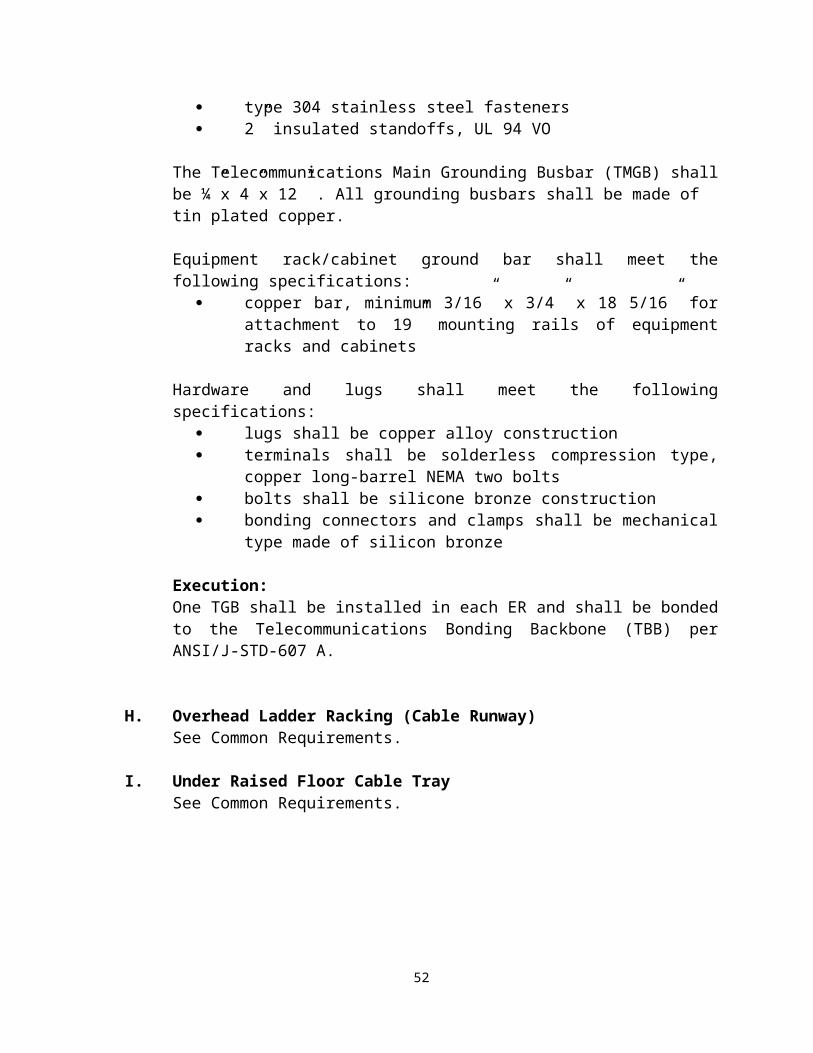
Corrugated Innerduct
Install three 1.25” corrugated innerducts in all 4” conduits where optical fiber cable will be installed.
Provide a ½” high strength foot-marked pull tape inside each corrugated innerducts and secure at each access point.
B. Hand Holes
Definition: A handhole is similar to a miniature vault that is used solely as a pulling point to expedite the installation of cable in conduit runs over 400-feet or with more than two 90° bends
ProductsTelecommunications Handholes
Handholes shall be used for outside cable installation. Handholes shall be provided at building entrances, both sides of road or parking lot crossings, at tie-ins to existing conduits and where multiple cable runs intersect.
Handholes shall be a minimum of 60” long by 36” wide and a minimum of 36” deep, with an open bottom, unless prior approval from the GTA RCDD is obtained.
Handholes shall have a minimum H-20 rated cover labeled “Telecommunications”.
A handhole shall not be used if the ultimate or total requirements exceed the capacity of two 4” conduits, in and out.
Where more than two 4” conduits are used in a duct bank, telecommunications vaults must be used in lieu of handholes.
Conduit entering the handhole shall be aligned on opposite walls of the handhole at the same elevation. Conduits are not permitted to enter the bottom.
Handholes placed inside Secured Areas (Prisons) must have lockable or bolt down covers, as approved by facility security personnel, to prevent unauthorized access.
Handholes shall be pre-cast polymer concrete type.
Adjust handhole depths as required to ensure minimum conduit depth is maintained throughout.
58

Handholes shall be installed a maximum of 400 feet (300 feet preferred) spacing to maintain proper cable pulling tension.
Typical Telecommunications Handhole
All handholes shall be equipped with two (2) 36” cable racks on each wall and four (4) 7.5” rack hooks for each cable rack.
ExecutionHandholes
Install top of the handhole flush with the finished grade.
All handholes shall have a minimum of 8” of gravel placed in the bottom..
Racking system shall be installed per the manufacturer’s instructions.
All conduits entering a handhole shall be sealed from the outside of the handhole prior to backfilling.
All conduits entering a handhole shall enter through the sides not the bottom.
59

C. Maintenance Holes
Products
Maintenance Holes
Maintenance holes shall be H-20 rated concrete or polymer concrete units provided with a removable lid that permits access via a ladder.
The minimum maintenance hole interior dimensions shall be 6 feet wide x 8 feet long x 7 feet high. The maximum depth of all maintenance holes shall be10 feet from the bottom unless prior approval from the GTA/RCDD is obtained.
All maintenance holes shall be equipped with a frame and cover. The maintenance hole cover opening shall be a minimum of 27” in diameter and shall be cast with the word “Telecommunications” and the maintenance hole number as required by the Using Agency. Maintenance hole covers shall have recessed handles or indented pick points. Double sealed maintenance hole covers with handles shall be used in areas with the potential of vandalism and/or flooding.
Telecommunications maintenance holes shall not be adjacent to nor share any walls with electrical maintenance holes. All materials used in a maintenance hole shall be resistant to corrosion. All steel shall be galvanized or zinc coated.
Maintenance hole racking equipment and cable supports are mandatory for all maintenance holes. All racks in maintenance holes shall be galvanized or zinc coated. Maintenance holes shall have pulling rings cast into the wall opposite to each conduit entrance. All metal components in the maintenance hole shall be grounded
All maintenance holes shall have cast-iron steps or ladders for climbing in and out.
All conduits entering a maintenance hole will be sealed from the outside of the maintenance hole prior to back filling. All conduits must be extended into the maintenance hole 4 inches and be clearly tagged. Any joints in maintenance holes are required to be watertight.
Maintenance holes shall meet applicable code requirements. In the absence of applicable codes, follow the National Electrical Safety Code (NESC).
Pre-cast maintenance holes shall conform to applicable ASTM standards.
Typical Maintenance Hole
60

The following is a list of required items for maintenance holes:
Identification Adequate working height Access Covers Ladders A sump hole Grounding rod Exposed straps required for bonding to the grounding system as required by
applicable electrical codes or practice for all metallic reinforcing members Interlocking reinforced concrete sections with dimensions to meet AASH Interim
specification 1972, Load factor design and ACI code 381-71 (USD) where applicable
Minimum strength in concrete compression requirement shall be 6000 PSI.
Execution
Maintenance Holes
Adjust frame to grade by providing a minimum of two (2) courses of bricks with all joints fully filled with mortar both inside and outside the collar. Provide layer of mortar on top course for bricks.
Provide cable racks with “T” slots for attaching support hooks. Provide a minimum of two (2) racks per wall.
Provide pulling irons on each wall 12” below duct.
61

Conduits shall enter maintenance holes in a splayed vertically stacked design 9” from the corner of the side walls and be terminated with bell ends.
Conduits shall be installed into the pre-cored knockouts starting on the bottom to allow for future expansion from the top.
The location of the maintenance hole cover layout and other details shall be shown on drawings and shall be clear of reinforcement bars.
Pulling eyes or iron opening shall be installed in the maintenance holes per manufacturer specifications.
Standard hardware required for construction and utilization of maintenance holes shall be installed. This includes rocking bolt assemblies, vertical support brackets, pulling irons, ladder support hooks, etc.
Maximum installed distances between maintenance holes shall not be greater than 400 feet for a single run containing an aggregate maximum of 45-degree bend, and not greater then 200 feet for single runs having an aggregate of 90-degree bend.
Telecommunications maintenance holes shall not be adjacent to nor share any walls with electrical maintenance holes.
D. Vaults ProductsTelecommunications Vaults
Telecommunications vaults shall be placed in OSP conduit runs at an interval no greater than every 400-foot. Conduits between two telecommunications vaults, or between a vault and a building, shall contain no more than two 90° bends or a total of 180° of bends. If additional conduit bends are required, place additional vaults as needed. Telecommunications vaults shall be constructed of concrete or polymer concrete, and contain a floor section, wall section, and top section. Vaults shall be sized based to adequately support the ultimate duct structure and equipment that will be located in the vault.
Telecommunications vault sections must be installed with a watertight joint sealer between the sections of the vault.
Telecommunications vaults shall be equipped with a pre-cast concrete floor section. Bare earth for the floor of a vault is not allowed. The floor section must contain a sump to facilitate the use of a submersible pump for de-watering the vault.
62

Telecommunications vaults must be equipped with steel pulling eyes pre-cast in the walls to facilitate cable-pulling apparatus.
Telecommunications vaults must contain cable racks for dressing and securing cables that route through the vault.
Telecommunications vaults over 5 feet deep must have permanently installed ladders.
All telecommunications vaults shall have a minimum of one grounding rod.
All metal hardware in the vault or handhole (racks & ladders) must be grounded to the bonding tabs pre-cast in the vault, with the bonding tabs bonded to the ground rod.
All telecommunications vaults located within secured areas must have either lockable or bolt down covers, as approved by local security personnel, to prevent unauthorized access.
The cover of all telecommunications vaults must be a minimum of 1” above the finished grade after all landscaping is completed. If vaults are located in paved areas, the pavement must be tapered up to the vault cover.
63
Typical Telecommunications Vault
Execution
Refer to Execution for Maintenance Holes, Section C.
E. Aerial Distribution
Products
Aerial Distribution
Aerial distribution of telecommunications cabling at State facilities is not permitted for new construction unless prior approval is obtained from GTA/RCDD.
Aerial Pathways
64

Aerial facilities consist of poles, support strand, cable and supporting pole hardware. Aerial cable is typically lashed to a cable support strand. An integral support strand may also support aerial cable.
AERIAL SUPPORT
Utility Poles
Only Class 5 poles shall be utilized
Messenger and Guying Strand
Provide “6M” or “10M” steel messenger strand specific to the application. Messenger strand shall to be manufactured to ASTM A475 specifications and be accepted by RUS standards.
Strand ConnectorsStrand connectors, suspension/cable clamps, grounding tap clamps, hangers, 1-bolt and 3-bolt clamps shall be rated to adequately support the strand.
Strand runs in excess of 15 feet between structural columns, additional ½” rod supports and appropriate strand clamps (such as 3-hole clamp) shall be provided and installed on minimum 25 foot centers.
Galvanized Steel Attachment Hardware
S type guy bolts, wall straps and brackets shall be used to adequately support the cable.
S type guy bolts (or commonly called anchor rods or thimble-eye bolts) shall be a minimum of 5/8” diameter with a straight shank and be designed for attaching messenger strand deadends. The bolt length shall be at least 4” longer than the width of the structural steel flange it will be attached to.
B type beam clamps, or approved equivalent, shall be specified for use when dead-ending strand on the flange of structural steel members (columns and beams).
Lashing Wire
Lashing wire shall be stainless steel type 430 with .045” minimum diameter.
Grounding Apparatus
All installations shall be grounded according to RUS and ANSI/TIA/EIA 758 requirements.
Guying Apparatus and Anchors
65

Guying Strand
Guying strand shall be “6M” or “10M” galvanized steel.
Guying strand shall be manufactured to ASTM A475 specifications and be accepted by RUS standards.
A minimum 8 foot safety yellow polyethylene guy strand cover is required.
Guying Anchor
Shall be an eight way anchor designed for installation in an 8” hole with 135 sq. in. area and shall include a ¾” thimble eye bolt.
Shall have a one piece top plate that expands upon impact into undisturbed earth to form a cone shaped square which distributes the anchors holding power over a wide area.
Anchor shall be covered with asphalt paint to protect against corrosive soil conditions.
Rod shall be hot dipped galvanized.
Execution
AERIAL SUPPORT
Utility Poles
Label as per RUS requirements and ANSI/TIA/EIA 606A.
Messenger and Guying Strand
Install all messenger strands to meet RUS requirements.
Strand ConnectorsStrand connectors, suspension/cable clamps, grounding tap clamps, hangers, 1-bolt and 3-bolt clamps shall only be utilized with prior approval from GTA/RCDD.
Galvanized Steel Attachment Hardware
Appropriate guy bolts, wall straps, brackets, etc., shall be installed to adequately support the strand
66
Guy bolts (or commonly called anchor rods or thimble-eye bolts) shall be a minimum of 5/8” diameter and be designed for attaching messenger strand deadends. The bolt length shall be at least 4” longer than the width of the pole to which it will be attached.
Lashing Wire
Cable straps / plastic cable ties shall NOT be used.Stainless steel type 430 lashing wire with .045” minimum diameter shall be specified.
Connect lashing wire to messenger strand using approved strand clamps.
Grounding Apparatus
Ground and bond all poles, messenger strand and any other metallic parts in accordance with RUS, the NESC and ANSI/TIA/EIA 758.
Guying Apparatus and Anchors
Guying Strand
Install guying apparatus per RUS.
Install protective guard on all down guys. Guards shall be Yellow in color.
Anchor
Install eight-way anchors designed for installation which includes a minimum ¾” thimble eye bolt.
Install one piece top plate that expands upon impact into undisturbed earth to form a cone shaped square distributing the anchors holding power over a wide area.
3.2.6 Administration & Labeling
Products
All pathway identification tags shall be a minimum of 3” square surface area, mechanically stamped, legible and permanently affixed.
Acceptable tagging materials are copper, brass or 1/16” thick plastic.
All tags shall be approved by the GTA/RCDD prior to use.
Handwritten labels are not permitted.
67

Execution
Each pathway shall be assigned a unique identifier. This identifier shall be recorded on all as-built drawings. The pathway identifier must also be recorded on the cable and equipment records. The pathway type, pathway fill capacity and current pathway loading shall be recorded for each pathway.
Each pathway shall be labeled within 6” of all endpoints located in all telecommunication spaces. The label shall show, as a minimum, the origin and destination of the pathway. The origin is always the point closest to the Equipment Room. All pathways entering and leaving pull-boxes shall be labeled. Partitioned pathways, such as a conduit with innerduct, shall have a unique identifier assigned to each partition.
All pathways shall be labeled with the appropriate designations per the ANSI/ TIA/EIA 606A standard.
3.3 Horizontal Pathways
3.3.1 Definitions
Approved Horizontal Pathway systems shall:
Consist of either zone or cable tray systems designed to support the installation of all telecommunications cabling.
Zoned System: consists of a system of TRs located to serve a floor area where the maximum allowable cable length is 250 feet. In this configuration all telecommunications cabling conduit and/or other support devices are "home-run" to the appropriate TR serving that zone.
Cable Tray System: consists of a system utilizing cable tray to support all telecommunications cabling. Radiating conduits and/or other cable support devices are provided from the cable tray to each Work Area Outlet (WAO). The total measured linear feet of cable shall be limited to 250 feet.
The Cable Tray System uses cable tray in conjunction with conduit, cable hangers, and other cable support devices. The cable tray shall be installed in the ceiling space above the major hallways in a configuration that provides the occupants with the most efficient and productive use of communications services.
3.3.2 Support Requirements
68

See common requirements.
3.3.3 Electrical Requirements
A. Grounding and Bonding
See common requirements.
3.3.4 Build-out Requirements
A. Pathway Systems
Products
Rigid Galvanized Steel Conduit
RGS conduit shall be hot-dipped galvanized steel, including threads.
Electrical Metallic Tubing
Electrical Metallic Tubing shall be Electro-galvanized steel.
Fittings
RGS fittings shall be fully threaded and shall be of the same material as the respective raceway system.
Compression type fittings shall be used for all conduits 2" and larger.
Provide plastic insulating bushings on each end of all conduits.
Die-cast or pressure cast fittings are not permitted.
The conduit may consist of two (2) types: rigid metallic and/or electrical metallic tubing. PVC is allowed only in wet and/or corrosive environments.
Rigid Metallic Conduit
Rigid metallic conduit (RMC) shall be industry standard, heavy wall steel conduit and shall have galvanized finish throughout.
RMC shall not be less than 1" trade size.
Running threads, split couplings and thread-less couplings shall not be accepted.
69

Electrical Metallic Tubing (EMT)
Electrical metallic tubing shall not be less than 1" trade size
All EMT conduits shall be cold rolled steel tubing with zinc coating on the outside and protected on the inside with zinc enamel or equivalent corrosion-resistant coating.
EMT couplings shall be all steel, hexagonal, compression type with all joints made tight. Follow installation practices as specified for rigid conduit.
Sizes and Capacities of Conduits
The following table gives the nominal conduit dimensions and the maximum number of cables that may be placed in them. A pull box or one trade size larger shall be specified if (a) the length is over 200 feet, (b) there are more than two 90 degree bends, or (c) there is a reverse bend in the run. If the type of communication or data system is unknown, the conduit size to be specified shall be 1” minimum.
Cable Type
Conduit Size 4 6 25 50 75 100In Inches Pair Pair Pair Pair Pair Pair
1" 8 6 3 1 0 01¼" 16 10 3 1 1 11½" 20 15 4 2 1 12" 30 20 7 4 3 22½" 45 30 12 6 3 33" 70 40 17 7 6 6
Outside diameter equivalencies:
6 pr. ca. = 1 coax RG 58, 59, or 6 optical fiber cable.25 pr. ca. = 1 IBM Type 1 cable50 pr. ca. = 1 Thick wire Backbone or .500 coax cable.100 pr. ca. = 1.750 broadband cable.
Conduits shall be sized as follows:
CONDUIT CAPACITY CHART
Cables with0.19OD
Cables with0.240 OD
70

Conduit Size
Capacity Capacity
1" 11 71 1/4" 20 131 1/2" 27 18
2" 44 292 1/2" 64 42
3" 98 65
3 1/2" 132 87
4" 170 112
Actual fill capacity shall be based on individual mfg OD using 40% fill capacity.
A drawing of all communications conduit, raceways, and outlets shall be a part of the contract drawings and updated to as-built conditions.
PVC rated conduit is not allowed above ceilings or in open warehouse ceiling areas.
In-floor Systems
Fixed “In-floor Systems” are generally not recommended.
Surface Mounted Raceway
Surface mounted raceway shall not be used for new installations but may be required for renovations.
Laboratory environments may require surface mounted raceway.
NOTE: Where installed in Department of Correction facilities SMR shall be metallic and twice the manufacturers recommended mechanical fasteners/attachments used in areas where inmates have access.
Modular Furniture Raceway/ Furniture Pathways and Spaces
When modular furniture is to be installed the fill requirements of ANSI/TIA/EIA -569-A, Commercial Building Standard for Telecommunications Pathways and Spaces shall be followed. The use of MUTOA’s or Consolidation Points shall be considered to facilitate flexibility of modular furniture systems.
The following items shall be addressed well before construction of the facility begins or before the furniture is specified
The Pathway Fill Factor
71

Furniture Pathway Capacity Access to the Furniture Pathway Furniture Pathway Bend Radius Power and Telecommunications Separation
Execution
Horizontal cabling pathways shall be installed in accordance with ANSI/TIA/EIA 569.
Conduits:
Install metallic bushings at all terminations in cable trays, freestanding conduits, and within boxes, enclosures and cabinets.Rigid metallic RMC conduit installation shall be made in accordance with industry standards for installation.
When installed above any ceiling use a minimum 1” Electrical Metallic Tubing (EMT) with set screw type fittings from the TR or cable tray to each work area outlet location. Insulating bushings shall be provided at each end of the conduit.
EMT may be installed in dry construction in sheltered spaces, in partitions other than concrete, and in solid plaster- work. EMT shall not be installed where:
it will be exposed to view below 8’ above finished floor, it may be subject to severe physical damage, it may be subject to severe corrosive influence, trade size is larger than 2", or tubing, elbows, couplings, and fittings shall be in concrete or in direct contact
with the earth.
All empty conduit runs shall have a nylon type pulling tape, string, or wire installed from the Work Area Outlet to the TR. This tape shall be continuous through all junction boxes. The pulling strength shall not be less than 200 pounds on either type of pulling facilities provided.
When installed below grade use a minimum 1” Threaded, Galvanized, Rigid conduit from the TR or cable tray to each work area outlet location. Insulating bushings shall be provided at each end of the conduit.
Provide a pull string in each conduit secured at both ends.
All conduits shall be installed by the Electrical Contractor or Low Voltage Contractor.
72

Electrical Metallic Tubing (IMC/EMC) and Rigid Metal Conduit are the only approved conduit types. Flexible metal conduit is not allowed.
When installed with cable tray, each conduit run must be metallically bonded to the cable tray.
Conduits larger than 1”shall be joined using compression fittings only.
All conduit fittings shall be installed per the manufacturer’s instructions.
Factory made sweeps shall be used for 1" trade size and larger.
Bend radius shall be 6 times the internal diameter for conduit sizes up to 2”.
Runs exceeding 100 feet or 180 degrees total bends shall be broken with suitable sized pull boxes. LB or similar conduit fittings are not allowed.
Conduit shall be supported as required by the manufacturer and the NEC.
Pull boxes shall not be located at bends.
Only sweeping bends shall be used.
Conduit runs to work areas shall serve no more than one (1) work area outlet.
During installation, cap all runs left unfinished or unattended overnight. Cap all terminations of finished runs with manufactured fittings to prevent ingress of moisture until wire and cable are pulled in.
No more than two 90 degree sweep bends or the equivalent shall be permitted between junction boxes, pull boxes, cabinets, or cable access points. The sweep bend radius shall not be less than 12".
Plug the ends of each roughed-in conduit with an approved cap or disc to prevent the entrance of foreign materials and moisture during construction.
Conduit shall be secured within three feet of each outlet box, junction box or fitting.
In Floor Systems
In floor Systems shall be installed in accordance with ANSI/TIA/EIA -569, Commercial Building Standard for Telecommunications Pathways and Spaces.
Floor boxes shall not be “daisy-chained”. A minimum of one 1” conduit or larger shall serve each floor box and extend to and metallically bonded to the cable tray in the hallway or Homerun to the nearest TR.
73

During construction the in-floor systems shall be sealed watertight to prevent moisture from accumulating in the conduits, boxes or raceway. Often the in-floor systems must be left exposed to the elements during construction since the floor slabs and all conduit contained within the slab are installed well before the building is “dried-in” or before a roof has been constructed.
Conduits installed in concrete floor slabs as follows:
Concrete slab on grade shall be treated as a wet environment.
Conduit in concrete floor slabs shall be galvanized rigid steel with concrete tight threaded fittings.
Provide expansion fittings where conduits cross building expansion joints.
Install conduit below the reinforcing mesh.
Locate conduits to provide a minimum of 1” of concrete around conduit.
Provide a neatly formed 4-in. high concrete envelope with chamfered edges around cluster when four (4) or more exposed conduits rise out of the floor.
Identification: Clearly label conduit and pull boxes within 6 inches of the exposed ends and as per ANSI/TIA/EIA 606A.
All conduit ends shall have insulating bushings installed.
Conduits shall not be installed adjacent to hot surfaces or in wet areas.
Provide expansion fittings with external grounding straps at building expansion joints.
Conduits, outlets, pull boxes, and junction boxes shall be installed to allow ergonomic access.
Install junction and pull boxes in readily accessible locations. Equipment, piping, ducts and the like shall not block access to boxes.
Surface Mounted Raceway
If metallic raceway is used, it shall be bonded and grounded in accordance with applicable code and ANSI/TIA/EIA – 607A.Surface mounted raceway shall be installed and filled in accordance with ANSI/TIA/EIA -569, Commercial Building Standard for Telecommunications Pathways and Spaces
74

The raceway shall be sized to insure less than a 40% fill with an additional 50% spare capacity to allow for future growth.
All surface mounted raceway must be identified and labeled on the print set with the contents and the “from-to” locations.
All surface mounted raceway shall be secured to walls with wall anchors and screws as per the raceway manufacturer’s requirements. Vertical sections of raceway shall be continuous from above the ceiling to the outlet box location 18” AFF. Adhesive (stick on) raceway is not allowed.
B. Sleeves and Slots
Products (See 3.1.4 B for common requirements )
Execution
Attach cored sleeves on each side of the floor / wall using 1.25” support struts and the appropriate conduit clamps to support the sleeves.
Cored sleeves shall extend a minimum of 3” through the finished wall on each side of the wall.
Cored holes shall be sealed as a barrier to prevent smoke and water infiltration between the core hole and the conduit.
C. Cable Tray
Products (Also see 3.1.4 C)
The cable tray shall be industry standard, ladder type trays shall consist of two longitudinal members (side rails) with transverse members (rungs) welded to the side rails. Rungs shall be spaced 6 inches on center. Wire basket-type tray may also be used.
Each rung must be capable of supporting the maximum cable load, with a safety factor of 1.5 and a 200 pound concentrated load when tested in accordance with NEMA VE-1, section 5.4.
The following table gives dimensions of cable tray by amount of floor space to be served. Cable tray shall be specified and can be 12 to 24” wide of aluminum or steel construction with 3” to 9" rung spacing.
Maximum allowable space to be served by one TR using the cable tray system
75

Floor Space to Be Served in Square Feet
Cable Tray Dimension
Up to 5,000 12"5,001 to 20,000 18"
20,001 to 35,000 * 18"
Shall be aluminum construction including accessories.
Maximum rung spacing shall be 9” on centers.
Minimum cable tray depth shall be 2”.
Rungs shall be welded to side rails.
Standard lengths shall be used.
Minimum radius of horizontal elbows shall be 12” Provide special radius elbows where required for field conditions.
Loading Data:
Useable Tray Width
Load Depth NEMA Depth
Std. Span Lbs/ Ft
Deflection
6” 4”
8” 4”
12” 4” 3” 12A 10’ 81 1.20”
12” 6” 5” 12B 10’ 112
0.59”
18” 4” 3” 12A 10’ 81 1.20”
18” 6” 5” 12B 19’ 112
0.59”
24” 4” 3” 12A 10’ 81 1.20”
24” 6” 5” 12B 10’ 112
0.59”
76

Execution
Cable trays shall be installed and filled in accordance with the ANSI/TIA/EIA -569 Series, Commercial Building Standard for Telecommunications Pathways and Spaces.
The cable tray shall be mounted above the finished ceiling in the main corridor. It is imperative that the cable tray be installed no less than 4” to 8” above the ceiling tile and have no less than a 24" horizontal clearance along one side and 6" above the tray. This will ensure that the cable tray is accessible.
No conduit, pipes, or HVAC duct shall rest on or extend through the cable tray.
Supporting hangers shall be attached along the cable tray sides and not within the cable tray bed.
The cable tray shall "tee off" if required and be run into the ER or TR. If the ER or TR wall is a firewall, the cable tray shall be terminated at the wall and 4" conduit sleeves provided into the room.
The number of 4" conduits penetrating the firewall shall not be less than two for the 12" cable tray and three for the larger cable trays.
Rooms directly adjacent to the TR or ER room may be directly served by home-run conduit, bypassing the cable tray.
Conduit shall be provided as a continuous run perpendicular from the cable tray to the WAO. Each conduit shall be metallically attached to the cable tray. All cable shall be routed in conduit or cable tray for protection.
The cable tray requires ceiling spaces that are accessible. Cable tray shall not be placed above permanent type ceilings or above offices. Sufficient quantities of four-inch EMT conduit shall extend across the inaccessible ceiling to cable trays in the accessible ceiling spaces
EMT shall be installed a minimum of 6 inches above the finished ceiling and a maximum of 2 feet above the finished ceiling and per manufacturer’s requirements and to the top of equipment rack.
The cable tray shall be supported at a minimum of five foot intervals from the ceiling and as the manufacturer recommends.
The cable tray shall be installed to allow access to both sides of the cable tray above the ceiling.
77

Cable radius drops shall be attached to the cable tray stringers or rungs to facilitate cable entering and exiting the tray while protecting the physical properties of the cable.
Communication grounding and bonding shall be in accordance with applicable codes and regulations. It is recommended that the requirements of ANSI/TIA/EIA-607and NEC be observed throughout the entire cabling system.
D. Alternate Cable Support
Products
J-hooks
Metal J-hooks are not allowed for new construction. J-hooks may be required in retrofit construction with written approval of the GTA/RCDD, but shall be rated to carry the category of cable to be installed, spaced as per the manufacturer’s recommendation and sized not to exceed the J-hook manufacturer’s recommended quantity of cables.
Cable Hangers
Cable hangers of the “Arlington Loop” type (e.g.: TL20 2” or TL50 5”) are the accepted cable hangers for all new construction and retrofitted cable installations.
Execution
Hangers shall be rated to carry the Category of cable to be installed, spaced as per the manufacturer’s recommendation and sized not to exceed the manufacturer’s recommended quantity of cables.
E. Boxes
Products
Outlet Boxes
Shall be galvanized steel, not less than 2 ¾” deep X 4 11/16" square with knockouts.
78

Outlet boxes exposed to moisture, exterior, wet or damp locations shall be cadmium cast alloy complete with threaded hubs, a gasket and screw fastened covers.
Boxes shall be approved for the environmental condition of the location where they will be installed.
Provide a single gang mud ring on all work area outlet boxes.
Except as noted, all boxes shall be manufactured from galvanized industry standard gauge sheet steel.
Flush mount outlet boxes shall be a minimum size of 4-11/16" square, with a minimum depth of 2-1/8", with vertical mounted single gang plaster rings and the standard mounting height shall be 18" centered above the finished floor or 6” centered above a backsplash in a countertop area. For classrooms, lecture halls, auditoriums, or designated multi-media rooms, the double gang electrical box shall be equipped with a double gang plaster ring with 1" radial conduit.
Each outlet box shall have two 1” conduits and each conduit shall have no more than two 90 bends between the outlet and the designated communications room or cable tray. If more than two 90 degree bends are required, a pull box shall be installed and the locations of pull boxes shall be shown on the drawings. The use of LB, LL, and LR fittings shall not be used without approval by the GTA/RCDD. Outlets shall not be looped in the same run of conduit.
Flush wall mount telephone outlets shall be 4-11/16" square with a minimum depth of 2-1/8", a mounting height of 48" to the center above the finished floor, and conduit entry from the top.
Interior surface mounted devices and raceways (exposed to view) to be metal type and shall be painted to match wall surface.
Junction Boxes Pull and Junction Boxes
Boxes shall be constructed of not less than 14 gauge galvanized steel with trim for flush or surface mounting in accordance with the location to be installed. Provide screw-on type covers. Boxes installed in damp or wet locations shall be of moisture tight construction with gasket covers and threaded conduit hubs.
79

Boxes shall not be sized smaller than as indicated in Article 370 of the National Electrical Code for conduit and conductor sizes installed. Boxes shall be approved for the environmental condition of the location where they will be installed.
Flush Floor Junction Boxes
Shall be recessed cover boxes designed for flush mounting in masonry. Provide brass diamond engraved cover plate with a gasket suitable for foot traffic. Provide connectivity face plates that fit the ITS installed and the floor box.Provide as shown on drawings.
Work Area Floor Boxes
Separate work area floor boxes shall be provided for communications and electrical devices.
Boxes shall be constructed of cast iron
Boxes shall house leveling screws for adjusting box to accept floor flange after pour.
Boxes shall support 1” conduit minimum.
Covers shall be flush with floor and hinged.
Wires shall enter the box through a pop up opening in the cover.
Verify the color with the Architect prior to ordering.
Provide connectivity face plates that fit the ITS installed and the floor box.
Execution
Outlet Boxes
Work area outlet boxes shall be installed by the Electrical Contractor to allow for ergonomic access.
Work area outlet boxes shall be installed only in readily accessible locations. Equipment, piping, ducts and the like shall not block access to boxes.
Conduit shall be secured within 3’of each work area outlet box.
80

Work area outlet boxes shall not be located at bends.
Junction Boxes
Junction boxes shall be installed to by the Electrical Contractor to allow for ergonomic access.
Junction boxes shall be installed in readily accessible locations. Equipment, piping, ducts and the like shall not block access to boxes.
Conduit shall be secured within 3’ of each junction box.
Junction boxes shall be anchored per manufacturer’s instructions.
Junction boxes shall not be located at bends.
Runs exceeding 100 feet or 180 degrees total bends shall be broken with suitable sized junction boxes. LB or similar conduit fittings are not allowed.
Identification: Clearly label all junction boxes per ANSI/TIA/EIA 606A.
F. Poke-throughs
Products
Separate poke through delivery systems shall be provided for communications and electrical devices.
Poke-throughs shall be suitable for floor thickness of up to 7”.
UL File #E146222 listing and ULR14686 fire resistant classification.
Shall be constructed of heavy gauge steel and be available in 2 gang, 4 gang or 8 gang arrangements.
Communications conduit shall be 1” diameter minimum.
Refer to details on drawing for the exact faceplate requirements.
Execution
Poke –throughs shall be pre-approved by the GTA/RCDD and the Architect.
Poke-throughs shall be installed by the Electrical Contractor.
81

Separate poke through delivery systems shall be installed for communications and electrical devices.
A minimum 1” diameter conduit shall be installed.
G. Utility Columns
Products
Utility columns, where required, shall contain a communication and electrical power divider.
The low-voltage channel shall be nominally 2" x 1.5” by the height required to extend above the ceiling. The above ceiling attachment shall be mechanical.
Each column shall be equipped with knockouts for two (2), 20 ampere, 125 volt, grounded, duplex receptacles, and knockouts for communications connection.
Columns shall be constructed of a minimum of .070" thick, anodized aluminum extrusion, with removable trim plate and cover.
Utility column shall be furnished with top plate mounting assembly for easy installation to accessible ceiling.
Execution
Utility Columns
All utility columns shall be installed by the Contractor, per the manufacturer’s installation instructions.
The above ceiling attachment shall be mechanical.
CABLING AND COMPONENTS4.0 Common Requirements
All horizontal cabling installed for the State of Georgia shall be installed in accordance with the Structured Cable System requirements. All horizontal cable shall be plenum rated (CMP) and shall be installed per the manufacturer’s 25 year warranty requirements. All installations shall require, in the final close out package to the Architect/Agency/GTA, a complete 25 year manufacturer’s warranty.
82

Horizontal cabling shall be installed in accordance with ANSI/TIA/EIA 568-B. One exception to the standard required by the state is to limit the horizontal distance of all cabling to 250 feet in order to provide an additional margin of reliability over and above the 295’ specified by ANSI/TIA/EIA 568-B.
4.1 Horizontal Distribution Cabling
4.1.1 Definitions
Horizontal distribution cable is the cable that extends from the telecommunications room to the work area outlet. The standard configuration for the State is to route a minimum of two 4-pair horizontal cables to each work area outlet. In all installations a minimum of Category 6 CMP UTP cable shall be used. Where additions are made to existing installations, Category 6 CMP UTP shall be used to complement the existing installation. The configuration may be adjusted to meet individual needs, provided that any adjustments comply with all codes, standards, and requirements of this manual and the manufacturer’s requirements. For example, a wall mounted telephone location need only have one horizontal cable. Or, a particular work area outlet may require more horizontal cables to support a computer, telephone, and fax machine. Splitting cable pairs from one cable to two or more connectors inside on outlet to avoid adding an additional 4-pair cable is not allowed – no exceptions. The addition of spare Information Outlet connectors at any given work area outlet, or the addition of spare Information Outlet locations on several walls of a room, is encouraged within the limitations of the project budget.
4.1.2 Build-out Requirements
A. Copper
Products
Horizontal UTP Cables
All unshielded twisted pair (UTP) horizontal copper cable supporting voice/data/video communications requirements, as well as Emergency, Courtesy, Pay Telephones and Wireless Access Points shall meet a minimum of Category 6 CMP UTP performance specifications per the ANSI/TIA/EIA 568-B series.
See ANSI/TIA/EIA-568B.2-1 for Performance Limits on Category 6 Cable
The state requirement for cable sheath color of the CMP UTP communications cabling shall be BLUE.
If blue cable is not readily available WHITE may be substituted without prior approval.
83

UTP Patch Panels
Physical Characteristics:
Panels shall be black anodized aluminum or thermoplastic in 48 (2RU) port configurations.
Panels shall accommodate a minimum of 24 ports for each rack mount space (1rms = 44.5 mm [1.75 in.]).
Shall have modular connectors with wire contacts constructed of Beryllium copper with minimum 50-micro inches of gold plating on contact surfaces over a minimum of 50 micro inches of nickel, compliant with FCC part 68.
Panels shall be available in Universal (T568A/T568B) cabling schemes. The state requires that the T568B termination scheme be used.
Panels shall be equipped with 110-style termination made of fire retardant UL 94V0 rated thermoplastic and tin lead solder plated IDC.
Panels shall have port identification numbers on both the front and rear of the panel.
Panels shall have rear cable support bars for strain relief.
Panels shall be labeled with factory white screened designation labels for each of the 48 ports.
Panels shall provide cabling identification & color code and maintain a paired punch down sequence that does not require the overlapping of cable pairs.
Panels shall terminate 22-26 AWG solid conductors, maximum insulated conductor outside diameter 0.050”.
Printed circuit boards shall be fully enclosed front and rear for physical protection.
Transmission Characteristics:
Panels shall be ANSI/TIA/EIA-568B Category 6 or higher compliant.
Panels shall be independently verified by a UL or ETL third party testing organization for ANSI/TIA/EIA Category 6 or higher electrical performance.
84

Panels installed in a channel with Category 6 connectors and patch cables shall be from the same manufacturer, and approved Category 6 cable shall meet the requirements of Category 6 channels listed in ANSI/TIA/EIA-568-B.2.
All panels, connectors and patch cables shall be from the same manufacturer and category compliant to support the SCS requirement.
UTP Connectors
The following UTP connectors may be utilized for installation:
ANSI/TIA/EIA T568B cabling scheme.
The ANSI/TIA/EIA T568A cabling scheme is not used by the State. Only the ANSI/TIA/EIA T568B cabling scheme is approved.
Physical Characteristics:
Connectors shall be 8-position non-keyed FCC compliant
Each connector shall be an individually constructed unit and shall snap-mount in an industry standard keystone opening (.760” x 580”)
Connector housings shall be high impact 94 V0 rated thermoplastic
Connectors shall have an operating temperature range of -10°C (14°F) to 60°C (140°F)
Connector housings shall fully encase and protect printed circuit boards and IDC fields
Modular connector contacts shall accept a minimum of 2000 mating cycles without degradation of electrical or mechanical performance
Contacts shall maintain a minimum vertical deflection force of 100 grams
Modular connector contacts shall be constructed of Beryllium copper for maximum spring force and resilience.
Contact Plating shall be a minimum of 50 micro inches of gold in the contact area over 50 micro-inches of nickel
Connector termination shall be industry standard 110 insulation displacement contact, integral to the connector housing, laid out in 2 arrays of 4 contacts
85

Connectors shall utilize a paired punch down sequence. Cable pairs shall be maintained up to the IDC, terminating all conductors adjacent to its pair mate to better maintain pair characteristics designed by the cable manufacturer.
Insulation displacement contacts shall utilize tin lead-plated phosphor bronze.
Connectors shall terminate 22-26 AWG stranded or solid conductors.
Connectors shall terminate insulated conductors with outside diameters up to .050”
Connectors shall be compatible with single conductor, industry standard 110 impact termination tools
Connectors shall include wire retention stuffer cap(s) to hold terminated wires in place while allowing conductors to be viewed in the IDC housing.
Connectors shall be compatible with EIA/TIA 606A color code labeling.
Manufacturers provide universal (T568A/T568B) cabling schemes marked as T568A, T568B or “Universal”. However, only the T568B cabling scheme shall be used in all State installations.
The different cabling configurations shall be clearly marked and easily readable.
Connectors shall have an attached color-coded cabling label for terminations.
Transmission Characteristics:
Connectors shall be designed for 100 Ohm UTP cable termination
Connectors shall be independently verified by a UL or ETL third party testing organization for ANSI/TIA/EIA Category 6 or higher electrical performance.
UTP Copper Patch Cables
All patch cables, patch panels and connectors shall be from the same manufacturer and shall be Category compliant with ANSI/TIA/EIA 568B Category 6.
Physical Characteristics:
86

Cables must be round, and consist of eight insulated 24 AWG, stranded copper conductors, arranged in four color-coded twisted-pairs within a flame-retardant jacket
Cables must be equipped with modular 8-position plugs on both ends, wired straight through with standards compliant cabling
Use modular plugs which exceed FCC CFR 47 part 68 subpart F and IEC 60603-7 specifications, and have 50 micro-inches minimum of gold plating over nickel contacts
Cables must be resistant to corrosion from humidity, extreme temperatures and airborne contaminants
Cables must be available in several colors with or without color strain relief boots providing snag proof design. Cables must meet the flex test requirements of 1000 cycles with boots and 100 cycles without boots.
Cables must be available in any custom length and various standard lengths as provided by the manufacturer.
Electrical Specifications:
Category 6 patch cables shall meet or exceed Category 6 component transmission requirements for connecting hardware, as specified in ANSI/TIA/EIA-568-B.2-1.
Horizontal Coaxial Video Cables
RG-6 Quadshield type cable shall be used.
If the run exceeds one hundred (100) feet, RG-11 type cable shall be used.
Cable Specifications:
All Cable must be 100% shielded
All cable must be 100% sweep tested and certified, 50-550 MHz. with no abrupt deviation from the loss figures supplied by the manufacturer of the cable.
Video Connectors
Compression type BNC connectors shall be used for CCTV/Security cables. Compression type F connectors shall be used for video coaxial cables, except
for the ½ inch trunk cable where “Pin” type connectors shall be used.
87

Connectors shall be sized to fit the appropriate cable being installed.
Video Termination/Patch Panels
Patch panels shall support F connector and/or BNC connector bulkheads.
Patch panels shall be 19” or 23” with 1RU size increments.
Wall mount units are approved.
All F bulkhead connections shall meet or exceed the performance Requirements of ANSI/SCTE 02-1997.
Execution
Horizontal UTP Cables
Maximum installed cable distance shall not exceed 250 feet. While the ANSI/TIA/EIA standards allow horizontal cabling to be 295 feet the State of Georgia wishes to ensure an additional margin of reliability by limiting horizontal cabling distances to 250 feet.
All work area outlets shall be installed in the locations as marked on the “T” drawings.
Prior to installing any cabling, floor plans and detail drawings indicating all connector numbering shall be pre-approved by the GTA/RCDD.
All horizontal UTP data cabling shall meet Category 6 standards (minimum).
All horizontal UTP cable shall be installed by the LVLTC per the manufacturer’s installation requirements.
All horizontal UTP cable shall be placed as shown on the “T” drawings.
All horizontal UTP cable concealed in walls or soffits shall be installed in metal conduits.
All horizontal UTP cable above ceilings shall be installed in cable tray, conduit, or approved cable hangers.
Do not untwist horizontal UTP cable pairs more than 0.5 in. when terminating.
Do not strip the insulation jacket from the individual pairs. IDC only.
88

Do not strip the cable jacket more than 0.5 in. from the IDC connection when terminating.
All installed horizontal UTP cables shall pass the Category 6 testing requirements of ANSI/TIA/EIA 568B.
Maximum installed horizontal UTP cable length shall not exceed 250 feet.
Horizontal UTP able shall have no physical defects such as cuts, tears or bulges in the outer jacket. Horizontal UTP cables with defects shall be entirely replaced.
Install horizontal UTP cable in neat and workmanlike manner per the BICSI Installation Manual.
All installed horizontal UTP cables shall be placed or routed per the manufacturer’s requirements.
Maintain the following clearances from EMI sources:
Power - 12 in. Fluorescent Lights - 12 in. Transformers - 36 in. Other systems, (e.g. energy management, video electronics, CATV) – 36 in.
UTP Patch Panels
The LVLTC shall install patch panels per manufacturer’s instructions. Manufacturer’s factory port labeling shall remain as part of ANSI/TIA/EIA
606A.
The Designer shall require the LVLTC to install front and rear horizontal cable management.
The Designer shall require the LVLTC to install ANSI/TIA/EIA 606A compliant labels for all patch panels.
Install UTP patch panels as shown on the “T” drawings.
UTP Connectors
89

The amount of untwisting in a pair as a result of termination to the connector IDC shall be no greater 0.5 inches (13 mm)
Do not strip the insulation jacket from the individual pairs. IDC only.
Do not strip the cable jacket more than 0.5 in. from the IDC connection when terminating.
Connectors shall be installed according to manufacturer’s instructions and properly mounted in plates, frames, housings or other appropriate mounting device.
Connectors shall be installed such that cables terminated to the connectors maintain minimum bend radius of at least 4 times the cable diameter into the work station outlet.
Cables shall be terminated on connectors such that there is no tension on the conductors in the termination contacts.
Testing:
Connectors shall be tested as part of the installed horizontal structured cabling system.
The Permanent Link shall be tested per ANSI/TIA/EIA 568B for Length, DC continuity, pair-to-pair, NEXT, PSNEXT, Attenuation, Return Loss, ELFEXT, and PSELFEXT using a level III tester (minimum) for Category 6 Permanent Link compliance.
A “PASS” indication shall be obtained for all link or channel tests.
Testers shall be correctly set to test the submitted type of the horizontal cable used in the link, including the correct NVP.
UTP Copper Patch Cables
The LVLTC shall provide to the Agency’s representative the quantity of pre-manufactured patch cables / cross-connection cables as stated in the specifications. The Agency’s representative shall determine the quantity of patch cables to be provided prior to the specifications being released for bid.
Horizontal Coaxial Video Cables
All horizontal coaxial video cables shall be installed by the LVLTC per the manufacturer’s installation requirements.
90

All horizontal coaxial video cables shall be placed as shown on the “T” drawings.
All horizontal coaxial video cables concealed in walls or soffits shall be installed in metal conduits.
All horizontal coaxial video cables above ceilings shall be installed in cable tray or conduit.
All installed cables shall pass the testing based on the ANSI/TIA/EIA 568B standard.
Maximum installed horizontal cable length shall not exceed 250 feet.
Horizontal coaxial video cables shall have no physical defects such as cuts, tears or bulges in the outer jacket. Horizontal coaxial video cables with defects shall be replaced.
Install horizontal coaxial video cables in a neat and workmanlike manner per the BICSI Installation Manual.
All installed horizontal coaxial video cables shall be placed or routed per the manufacturer’s requirements.
Maintain the following clearances from EMI sources: Power - 12 inches Fluorescent Lights - 12 inches Transformers - 36 inches
Video Termination/Patch Panels
Video termination/patch panels shall be installed and terminated in a separate dedicated equipment rack by the LVLTC.
Label as recommended by manufacturer, per all ANSI/TIA/EIA 606A.
Front and rear horizontal cable management shall be installed as recommended by the manufacturer.
The Designer shall require the LVLTC to install ANSI/TIA/EIA 606A compliant color-coded icons or color-coded designation label strips for all patch panels.
Install video termination/patch panels as shown on the “T” drawings.
Video Connectors
91

Connectors shall be installed by the LVLTC per manufacturer’s requirements.
Other Multimedia Connectors
Connectors shall be installed by the LVLTC according to the manufacturer’s instructions and properly mounted in plates, frames, housings or other appropriate mounting device.
B. Optical Fiber
Products
Duplex Optical Fiber Cables
Physical Characteristics:
Optical fiber cables shall be tight buffered two strand, zip cable type, 50/125m multimode optical fiber for horizontal cabling. Retrofit installation may require the use of 62.5/125 multimode optical fiber or 8.3/125 single mode optical fiber to match the existing system.
Optical fiber cable shall be appropriate for the environment in which it is installed
Multimode optical fiber cables shall meet all of the requirements delineated within the specifications of ANSI/TIA/EIA-526 and 568B
Transmission Characteristics:
Attenuation
Multimode optical fiber cable and single mode optical fiber cable shall perform in accordance with the attenuation limits when tested per ANSI/TIA/EIA-455 and 526.
Bandwidth
Multimode and single mode Optical fiber cables shall perform in accordance with the bandwidth limits when tested per ANSI/TIA/EIA-568B.3.
Transmission Distance
The protocol pertinent to the transmission distance for Multimode cable is stated in IEEE 802.3z (Gigabit Ethernet).
92
Zero Dispersion Wavelength and Slope
Multimode cable shall perform in accordance with the Zero Dispersion wavelength and slope limits when tested per ANSI/TIA/EIA-568B.3.
Optical Fiber Termination/Patch Panels
Optical Fiber Panels - rack mounted (low fiber count)
All panels and trays (units) shall provide cross-connect, inter-connect, splicing capabilities and contain cable management for supporting and routing the fiber cables/jumpers.
Panels shall be available in 12 and 24 port with no splicing.
Panels shall be constructed so as to allow mounting in 19” equipment racks.
Panels shall be constructed so as to allow flush or 5” recess mounting.
Panels shall be black.
Panels shall meet or exceed ANSI/ANSI/TIA/EIA 568-B.3 requirements.
Provide port configurations and densities as called for on the “T” drawings.
Wall mountable Optical Fiber Panels may be used in the absence of an existing rack, or when conditions warrant the use of a wall mounted enclosure.
Panels shall have a hinged removable front cover.
Panels shall feature a front access design with a hinged bulkhead plate.
Panels shall house a minimum of 6 adapters per adapter plate. If using small form Optical Fiber connectors such as LC-type or MTRJ-type, there shall be a minimum of 12 adapters per adapter plate.
Optical Fiber Panels - rack mount (Moderate fiber count)
All panels and trays (units) shall provide cross-connect, inter-connect, splicing capabilities and contain cable management for supporting and routing the fiber cables/jumpers.
Panels shall be available in 12, 24, 48, 72 and 96 port configurations.
93

Panels shall feature a front access design with hinged bulkhead plate.
Panels shall have a hinged removable front cover.
Panels shall have an integrated vertical cableway on one side of the panel.
Panels shall be mountable in flush and recess options.
Panels shall be19” or 23” rack mountable. Wall mountable Optical fiber Panels may be used when a rack does not exist or when conditions warrant the use of a wall mounted enclosure.
Panels shall have storage and splicing options as part of the product offering.
Panels shall provide port configurations and densities as called for on drawings.
Optical fiber Panels - rack mount (high fiber count)
All panels and trays (units) shall provide cross-connect, inter-connect, splicing capabilities and contain cable management for supporting and routing the fiber cables/jumpers.
Panels shall be made of 12-gauge aluminum alloy.
o Panels shall have blank adapter plates for future growth of the fiber infrastructure.
Panels shall have fiber managers to effectively store fiber cable slack and comply with fiber bend radius requirements.
Panels shall have a minimum of six port fiber adapter plates. If using small form Optical fiber connectors such as LC-type or MTRJ-type, there shall be a minimum of 12 adapters per adapter plate.
Panels shall accommodate stackable splice trays
Panels shall have an adapter plate-mounting bracket, which slides out to the front and to the rear of the unit for increased access.
Panels shall have cable access points for fiber jumpers entering and exiting the unit to minimize micro-bending stress.
Panels shall have anchor points for fiber cable(s) entering the unit.
94

Panels shall have labeling which meets ANSI/TIA/EIA-606A requirements.
Panels shall be19” or 23” rack mountable. Wall mountable Optical fiber panels may be used when a rack does not exist or when other conditions warrant the use of a wall mounted enclosure.
Panels shall be UL listed.
Panels shall provide port configurations and densities as called for on the “T” drawings.
Execution
Horizontal Duplex Optical fiber Cables
All horizontal duplex optical fiber cable shall be installed by the LVLTC per the manufacturer’s installation requirements.
All horizontal duplex optical fiber cable shall be placed as shown on the “T” drawings.
All horizontal duplex optical fiber cable concealed in walls or soffits shall be installed in metal conduits.
All horizontal duplex optical fiber cable above ceilings shall be installed in cable tray or conduit.
All installed horizontal duplex optical fiber cable shall pass the testing requirements of ANSI/TIA/EIA 568B.
Maximum installed horizontal duplex optical fiber cable length shall not exceed 250 feet.
Horizontal duplex optical fiber cable shall have no physical defects such as cuts, tears or bulges in the outer jacket. Horizontal duplex optical fiber cable with defects shall be replaced.
Install horizontal duplex optical fiber cable in a neat and workmanlike manner per the BICSI TDMM Installation Manual.
All installed horizontal duplex optical fiber cable shall be placed or routed per the manufacturer’s requirements.
Optical fiber Termination/Patch Panels
95

The LVLTC shall install as shown on the “T” drawings.
The Designer shall require the LVLTC to furnish and install labels for each fiber strand, as shown on the “T” drawings.
The Designer shall require the LVLTC to install blank adapter panels in all positions not used at time of installation for fiber terminations.
Each panel shall be labeled as recommended by the manufacturer and per ANSI/TIA/EIA 606A.
The Designer shall require the LVLTC to install front and rear horizontal cable management as recommended by the manufacturer.
Optical fiber Connectors
Connectors shall be installed by the LVLTC to provide minimal signal impairment by proper termination techniques.
Connectors shall be installed according to manufacturer’s instructions and properly mounted in plates, frames, housings or other appropriate mounting device.
Connectors shall be installed such that cables terminated to the connectors maintain minimum bend radius of at least 6 times the cable diameter into the work station outlet.
Fibers shall be terminated such that there is no tension on the conductors in the termination contacts.
The Designer shall require the LVLTC to adhere to all of the optical fiber cable manufacturers’ installation guidelines.
Testing
The installed, terminated optical fiber plant shall be tested using an Optical Loss Test Meter.
The Designer shall require the LVLTC to follow the Optical Loss Test Meter manufacturer’s specific instructions for testing the fiber link losses.
Connectors shall be installed and tested with less than .5 dB of attenuation.
Test Results shall conform to ANSI/TIA/EIA-526-14A Optical Power Loss Measurements of Installed Multimode Fiber Cable Plant.
96
Optical fiber Patch Cables
The Designer shall require the LVLTC to provide to the Agency’s representative with the quantity of pre-manufactured patch cables / cross-connection cables as stated in the final specifications. The Agency’s representative shall determine the quantity of patch cables to be provided prior to the specifications being released for bid if patch cables are to be provided as part of the project.
C. Wireless
This manual is not intended to address the design of Wireless LAN systems. In general Wireless LANs shall be installed only as extensions or additions to hard-wired LANs and not as a replacement for cabled voice, data or video networks. When considering the installation of a wireless LAN it is recommended that proprietary systems not be utilized due to incompatibilities between manufacturers. The IEEE has issued and continues to develop a series of standards intended to expand existing local area network (LAN) capabilities by including wireless functionality. There are three working groups that address a specific type of wireless network
The IEEE 802.11 working group is responsible for wireless LAN (WLAN) specifications. WLANs like cabled LANs, serve a group of users and their computing devices in a common space, such as an office in a commercial building.
The IEEE 802.15 working group is responsible for wireless personal area networks (WPAN) specifications. WPANs are intended to serve the connectivity needs of a single individual, linking items such as printers, scanners and the desktop computer in one work area.
The IEEE 802.16 working group is responsible for wireless metropolitan area networks (WMAN) specifications. WMANs are being developed to provide high-speed connections to a large number of users over a dispersed or extended area.
Specifications in the form of approved standards have been issued only by the IEEE 802.11 WLAN working group.
Allowable distances for a wireless system depend heavily upon the site where the system is to be installed. The design of the network is guided by inspections and tests performed at the site, also referred to as a site survey, site verification or environmental analysis. Both physical and environmental barriers shall be identified and accommodated in the design.
The following guidelines are provided to classify and rank potential obstructions:
97

Level 1 – Open Environment
No obstructions exist between the potential sender and receiver
A reliable estimate for the point-to-point distance of 2.4GHz signal is a minimum of 394 ft but may be as high as 656 ft.
Level 2 – Partially Open Environment
Environment contains low-severity barriers (e.g., partitions made of wood or other synthetic materials)
A reliable estimate for the point-to-point distance of 2.4GHz signal is a minimum of 98 ft but may be as high as 164 ft.
Level 3 – Closed Environment
Environment contains moderate severity barriers (e.g., floor to ceiling walls made of brick or plaster
A reliable estimate for the point-to-point distance of 2.4GHz signal is a minimum of 50 ft but may be as high as 82 ft.
Level 4 – Obstructed Environment
Environment contains high-severity barriers (e.g., metal reinforced concrete walls, elevator shafts or machinery)
The maximum reliable estimate of point-to-point coverage distance is 33 ft with a 2.4GHz signal.
Horizontal Cabling Design Considerations for Wireless LANs
The minimum of one Category 6 outlet shall be provided for each access point.
The access point must be located within 250 ft of a TR.
Standard outlet boxes as provided for data outlets shall be provided for access points and shall be mounted flush in the suspended ceiling or 18 inches below the finished ceiling in walls. One-inch EMT shall be provided from the Access point box to the cable tray or home run to the nearest TR.
The GTA/RCDD shall be contacted before designing or installing any wireless systems. The GTA/RCDD will arrange to perform a wireless site survey for coverage and frequency considerations before determining the wireless access point locations.
98

4.1.3 Administration & Labeling
Product
Use Self adhesive, self laminating mechanically printed with a clear protective laminating over-wrap or mechanically printed heat shrink tubing.
Execution
Horizontal cables shall be marked at each end of the sheath indicating the Telecommunication Room, patch panel and panel port to which the horizontal cable is terminated.
The Designer shall require the LVLTC to permanently secure the label within 6 inches from both ends of the cable and at all pull boxes.
Cables shall be labeled with the appropriate designations per the ANSI/TIA/EIA 606A standard. Patch panels: (Example: If three patch panels are required in an equipment rack the top most panel shall be labeled “A” and use the factory port numbering of 1-48 as designators, the second panel shall be labeled “B” and use the factory port numbering of 1-48 as designators, the third panel shall be labeled “C” and use the factory port numbering of 1-48 as designators, etc.)Work Area Outlets (WAO): Each connector in the WOA shall be labeled to reflect the appropriate patch panel location. “A”,”B” or “C” 1-48. (Example: WAO has two connectors installed and labeled “B”19 and “B”20 are connected to patch panel “B” ports 19 & 20). If more than one TR is used then a designator of the room number shall be added to the numbering scheme. (Example: TR 149 –“B”19).
4.1.4 Other Cabling Systems/Issues
Radio System Distribution
State of Georgia facilities frequently use wireless or radio systems for communications with mobile units and personnel, both on and off of the campus. These systems typically have one or more radio antennas connected by cabling to radio transceiver equipment. In many cases, the radio equipment is interfaced into the telephone system. The OSP telecommunications substructure must provide adequate cable routing pathways between antenna locations, radio transceiver locations, and the telephone backbone cabling system.
Radio antenna transmission cables that connect the antenna to the radio transceiver contain radio frequency (RF) radiation. These cables may be routed through the common telecommunications duct bank and vault system if necessary, but shall be
99
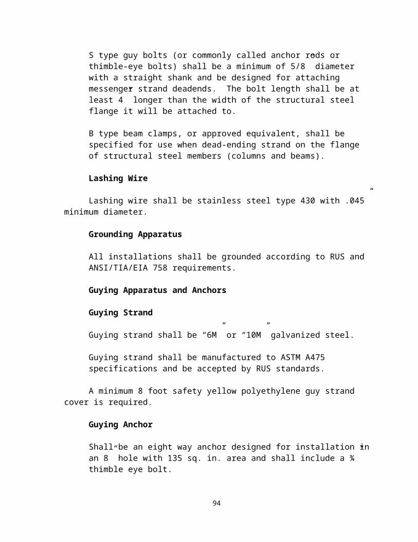
routed in a separate conduit from other telecommunications cables. Cables containing RF radiation must be shielded cables.
Radio transceivers may interconnect to remote radio operating positions, or to the telephone system. These interconnections are typically accomplished using standard telephone cabling. These interconnection cables shall be routed through the common telecommunications duct bank and vault system. Individual conduits may be shared for these interconnection cables and other telecommunications services, and available cable pairs in telephone backbone cables may be used for these interconnections, provided that the signaling is analog or digital signaling, and does not contain radio frequency radiation.
Removal of Abandoned cables
Article 800 of the 2005 edition of the National Electrical Code states that; “Accessible portions of abandoned communications cables shall not be permitted to remain”. Therefore in retrofit or renovation scenarios all cable that is not to be reused must be removed. Communications cables that will be used in the future must be tagged “for future use”.
Firestopping
Firestopping protection shall be installed by the LVLTC and shall meet NFPA Life Safety Code #101, 6-2.3.6, "Penetrations and Miscellaneous Openings and Fire Barriers" and the NEC 300.21 "Fire Stopping" regulations and standards. All vertical penetrations consisting of conduits, sleeves, or chases shall be firestopped at the top and bottom of each penetration. All horizontal penetrations consisting of conduits, sleeves or pipe chases shall be firestopped on both sides of each penetration. Openings made in concrete floors shall be firestopped using a tested system.
Thickness, depth and installation of firestop materials shall be as recommended by the material manufacturer and backed by formal ASTM E-814 tests. Plenum air return ceiling penetrations for conduit shall be sealed with a system appropriate for the substrate and the level of protection required.
All metal conduits designed for telecommunications with or without cable installed shall be firestopped to prevent transfer of smoke.
During construction all slots and sleeves shall have firestopping pillows installed.
All firestopping pillows shall be reinstalled daily during cable installation and at no time shall conduits, slots or sleeves be left unprotected with firestop material.
100

All sleeves must have a firestopping caulk applied to the outside circumference of the sleeve on each side of the wall penetration and from the top and bottom of a floor penetration.
Backbone Cabling to Support Inmate and Pay Telephones
Backbone cabling, to support inmate telephone service, shall meet all of the same requirements for voice backbone cables above, plus the following additional requirements:
All newly installed inmate telephone backbone cables shall be separate cables (separate sheath) from all other voice and data services.
All inmate telephone backbone cables shall have separate termination blocks from all other services.
All inmate cabling must have an easily accessible disconnect point to disable service.
All inmate telephone cables and termination hardware shall be identified with the color yellow, to indicate auxiliary circuits.
All inmate telephone cabling must be installed in metallic conduits and properly secured to the building infrastructure.
4.2 Intra-Building (within buildings) Backbone
4.2.1 Definitions
Intra-Building backbone cables are primary connectivity media for copper and fiber services within the building, either risers or feeders connecting multiple telecommunications spaces. The copper intra-building cables are installed from the SEF to each ER, TR or MER connecting multiple floors or spaces for voice services only. The fiber intra-building cables are installed from the SEF to each ER, TR or MER connecting multiple floors or spaces for data, system management, controls and voice services. The properly NEC rated cable is required in all instances.
4.2.2 Build-out Requirements
A. Copper
Products
Cables
101

Copper risers and feeders shall be rated for the specific use, see the NEC article 800. Cables shall be available in 25, 50, 100, 200, 300, etc. pair configurations and be sized to not exceed an installed use rate of more than 50% (i.e. 50 dial tones requires 200 pair).
Termination Blocks (Used for voice connectivity only)
The connecting hardware block shall support up to Category 6 or higher applications and facilitate cross-connection and/or inter-connection using either approved cross-connect wire or patch cables.
Terminations shall be 110 type Insulation Displacement Connector (IDC) blocks shall be UL -Verified
Terminations shall be ANSI/TIA/EIA-568 Category 6 compliant.
Be made of flame-retardant thermoplastic.
Blocks shall be 50, 100 or 300 pair sizes.
Blocks shall include means to identify cables/services per ANSI/TIA/EIA-606A.
Blocks shall have clear label holders with the appropriate colored inserts available for the cabling blocks. The insert labels provided with the product shall contain vertical lines spaced on the basis of circuit size (3, 4 or 5 pair) and shall not interfere with running, tracing or removing jumper wire/patch cables. Label holders must be capable of mounting in the under portion of the cabling block.
Connecting blocks shall be used for either the termination of cross-connect (jumper) wire or patch cables. The connecting blocks shall be available in 3, 4 and 5 pair sizes. All connecting blocks shall have color-coded tip and ring designation markers and be of single piece construction.
Support wire sizes of solid or 7-strand 22-26 AWG.
Execution
CablesCables shall be installed with the proper rated hanger hardware in neat bundles without excess bends or jacket disfiguration. All cables shall be labeled per TIA/EIA 606A at every accessible location.
UTP Termination Blocks
102

Blocks shall be installed by the LVLTC on the proper backboard so that the top of the termination block is 5’6” AFF or in equipment racks as noted on the “T” drawings.
Blocks shall be mounted with steel, zinc plated 5/16” - #10 x 3/4" drill screws with a minimum of four screws per block.
B. Fiber Products
Fiber risers and feeders shall be rated for the specific use, see the NEC article 800. Cables shall be available in sizes that permit use by all platforms (System Controls, LAN, etc.). Single mode and multi-mode cables may be bundled or hybrid type.
Execution
Cables shall be installed with the proper rated hanger hardware in neat bundles without excess bends or jacket disfiguration. All cables shall be labeled per TIA/EIA 606A at every accessible location.
4.3 Inter-Building (between Buildings) Backbone
4.3.1 Definitions
Customer Owned OSP
The Customer Owned OSP telecommunications infrastructure includes the backbone pathways (Also see section 3.2) and backbone cabling (fiber & copper) required to interconnect and provide service for telecommunications between buildings on a University, College, Medical or other campus.
Customer-Owned OSP Telecommunications infrastructure shall be installed in accordance with ANSI/TIA/EIA -758, current Customer-Owned OSP Telecommunications Standard.
This section provides the necessary information to install duct banks, maintenance holes, service entrances to buildings, and information for the termination of cables entering buildings.
All OSP telecommunications conduit and maintenance hole designs shall be approved in writing by the GTA/RCDD prior to installation.
Backbone cables are the major service cables that interconnect various buildings on a campus, connect equipment rooms (ERs) to telecommunications rooms (TRs) within a building, or connect one telecommunications room to another within the same building.
103

Backbone cables are typically large capacity (high pair count) copper cables for voice, optical fiber cable for data and coaxial cable for video.
Voice (telephone) backbone cable will typically originate at the location of the facilities telephone system. The backbone cables will route to the various buildings on the campus, and/or the various floors of the building to distribute telephone service to the telecommunications rooms. Voice backbone cables shall meet the following requirements:
Voice backbone cables shall be minimum Category 3 cables and it is recommended to have an overall metallic shield.
Voice backbone cables installed in underground conduits shall be PE gel filled cables
The shield of all backbone cables shall be bonded to the Telecommunications Main Grounding Bus bar.
Voice backbone cables shall be sized to support 2-pairs per each voice station, plus 25% growth. When calculating size, voice stations shall also include fax machines and dial-up modems.
4.3.2 Common Requirements
Prior approval and coordination with the GTA/RCDD and other concerned parties is necessary when the situation requires pulling cable through a conduit occupied by other cables. All cables associated with campus telecommunications networks (telephone, data, LAN, WAN, cable television and optical fibers) shall be connected and disconnected only with the Using Agency’s approval.
Only those cables specified within this document shall be installed. There shall be no cable with voltages higher than 48 volts in communications duct banks except electrical feeders for sump pumps and lights and electrical outlets in vaults.
Circuits for lights and outlets shall be installed according to the National Electrical Code requirements for wet locations and shall be isolated in separate conduits.
Fiber cables shall be sized to meet the minimum state standard size of 24 strands multimode and 24 strands single mode for inter-building connection. Smaller sized cables may only be installed with approval in writing from the GTA/RCDD.
4.3.3 Build-Out RequirementsA. Copper
General
Underground low voltage cabling shall be installed in duct banks. No aerial cable or direct burial cable shall be installed unless pre-approved by the GTA/RCDD.
104

Information about ownership of aerial cables and poles shall be obtained from GTA prior to placement.
Products
Inter-building Backbone Video Cabling
For video and broadband (CATV) applications up to 1 Ghz, 75-ohm semi-rigid coaxial cable may be utilized. The electronics to compensate for cable loss and to equalize signal levels shall also be provided.
Multimode and single-mode optical fiber cable may be used for CATV and video backbone cabling. When optical fiber cable is used, additional strands shall be provided over and above the recommended minimum for any other type of installation.
Customer Owned Underground Copper Backbone Cables
Copper backbone cables shall consist of paired 24 AWG solid annealed copper conductors per RUS PE 89 specifications.
Cable shall be suitable, listed and marked for use in a duct application.
Manufacturer’s cable ID, pair count along with month and year of manufacture shall be marked on cable a minimum of every two feet.
Customer Owned Aerial Copper Backbone Cables
GTA shall be contacted prior to the design or installation of any aerial cable.
Copper Backbone Cable Splice Closures
All closures shall consist of split aluminum or PVC sleeves.
Minimum inside diameter shall be 5".
Minimum inside length shall be 26".
All closures shall be sized to accommodate the maximum number of cable pairs to be spliced and the type of splice connector.
All closures shall be flame retardant and re-enterable.
All installed closures shall be airtight (10 lbs.) and watertight.
105
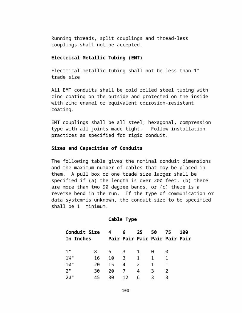
Splice Closure End Caps
End caps shall be sized precisely to fit the diameter of the cables entering the closure.
Collared Cap opening may be a maximum of 1/4" larger than the feed cable diameter.
Plugs
Use tapered or collared plugs as required to fill and seal extra opening in end caps.
Bushings
Rubber or variable bushings shall be used and sealed as required to reduce standard opening in end caps.
Lubricants
Lubricant shall be self-evaporating.
Sealing Kits
Kit shall consist of a urethane adhesive for sealing split vault sleeves and split end caps.
Clamps
Sleeve and Collared clamps shall be required.
Bonding Harnesses
Harnesses shall be used to ground the shields of the spliced cables.
Bonding harness shall be 14 AWG and sized according to closure.
Splicing Modules
All splicing modules shall have an integrated encapsulate in all environments (ISP and OSP).
Crimping process shall strip the installation from the wire and trim the excess wire.
The module shall create a gas-tight connection.
All modules shall have a test entry port.
106

Splicing Tapes
Shall be an all-weather UV-resistant vinyl plastic material and resist water, acids and alkalis.
Shall be flame retardant.
Shall release smoothly in zero weather and not release adhesive in hot climates.
Bonding Connectors
Shall consist of a base and upper member, two securing nuts and a plastic shoe to aid connector installation and protect the conductors.
Base and upper members shall be made of tin plated tempered brass and be slightly curved so as to exert a continuous spring form on sheath and shield after clamping.
Grounding Braid
The grounding braid shall be a flat, tin-plated copper braid conductor.
The grounding braid shall have eyelets at regular intervals that fit shield connector studs up to 1/4" in diameter.
Copper Backbone Primary Cable Protection
Entrance Facility Terminals
Entrance Facility terminals shall protect a minimum of 100 lines/ (pairs). Smaller sizes that accommodate smaller projects must be approved in writing by the GTA/RCDD.
Dimensions shall be a minimum 4"W x 12"H x 3.95" D
The input stub cable shall be 26 AWG shielded cable.
The input stub shall serve as internal fuse link.
Input stub shall be equipped with a heavy-duty strain relief and encapsulated cable connector.
Output stub cable shall be 24 AWG shielded cable.
107

Shall be wall or frame mountable
Shall accommodate industry standard 5-pin protection modules
Plastic components shall meet or exceed specifications as set forth in UL 497.
Surge Protection Modules
Shall be 5 pin, 3 element gas type protection modules
Module shall provide true balanced operation.
Over voltage on either side shall cause the entire tube to ionize to provide a simultaneous path to ground for both sides of the circuit.
Shall be UL 497 listed.
Ground pin shall be tin.
Tip and Ring pins shall be gold alloy.
The module color shall be black.
The module color shall be green for spare pair modules.
The nominal DC Breakdown shall be 350V @ 100V/sec.
The impulse breakdown voltage shall be 700A @ 100V/sec and 150A @1KV/sec.
The DC holding current shall be 135V for <150ms.
The Surge life (min. operations) shall meet manufacturers’ specifications.
Backbone Copper Cable Termination Blocks
The connecting hardware block shall support Category 5e or Category 6 applications and facilitate cross-connection and/or inter-connection using either approved cross-connect wire or patch cables.
Shall be 110 type Insulation Displacement Connector (IDC) blocks.
Be UL -Verified
Be ANSI/TIA/EIA-568 B.1 Category 5e or Category 6 compliant.
Be made of flame-retardant thermoplastic.
108

Blocks shall include means to identify cables/services per ANSI/TIA/EIA-606A.
Have clear label holders with the appropriate colored inserts available for the cabling blocks.
The insert labels provided with the product shall contain vertical lines spaced on the basis of circuit size (3, 4 or 5 pair) and shall not interfere with running, tracing or removing jumper wire/patch cables. Label holders must be capable of mounting in the under portion of the cabling block.
Have connecting blocks used for either the termination of cross-connect (jumper) wire or patch cables. All connecting blocks shall have color-coded tip and ring designation markers and be of single piece construction.
Support wire sizes: Solid or 7-strand 22-26 AWG.
Multi-pair Copper Cables
The multi-pair copper cables shall be sized as indicated on the drawings.
Shall consist of a core of 24 AWG solid annealed copper conductors, color coded in accordance with telephone industry standards.
Cable shall be suitable, listed and marked for use in a duct application.
The manufacturers’ cable code, pair size, manufacturing plant location, month and year or manufacture shall be marked on cable every two feet.
Coaxial Video Cables
All inter-building coaxial cable shall be engineered for the application and meet the requirements of the SCTE.
Copper Cable Splice Cases
Closure shall consist of a split Aluminum or PVC sleeves as indicated on the drawings.
Minimum inside diameter shall be 5" (127mm).
Minimum inside length shall be 26" (660mm).
Actual sizes shall be indicated on the drawings. Otherwise, closures shall be sized to accommodate the maximum number of cable pairs to be spliced and the type of connector to be used for splicing.
109

Closure shall be flame retardant.
Closure shall be re-enterable.
When assembled with properly sized end caps, bushing, plugs and clamps, the closure shall be air and water tight.
Splice Closure End Caps
End caps shall be sized precisely to fit the diameter of the tip cables entering the closure.
Number of openings in the multiple end caps shall be determined by dividing the number pairs in the feed cable by 100 and doubling that number. (i.e. 1200 pair cable would have 24 openings for tip cables.
Collared Cap opening can be up to 6.35mm (1/4") larger than the feed cable diameter.
Actual end cap to be provided shall be based on the diameter of the feed cable to be spliced.
Plugs
Use tapered or collared plugs as required to fill extra opening in end caps.
Seal if inside diameter of hole is less than 6.35mm (.25").
Bushings
Use rubber or variable bushings as required reducing standard opening in end caps to accommodate custom diameters.
Seal if inside diameter of hole is less than 6.35mm (.25").
Lubricants
Lubricant shall evaporate and shall not damage closure elements in any way.
Sealing Kits
Kits shall consist of a urethane adhesive designed for sealing split vault sleeves and split end caps.
Clamps
110

Provide Sleeve and Collared clamps as required to complete work.
The Designer shall require the LVLTC to adhere to all manufacturers’ installation guidelines.
Bonding Harnesses
Harnesses shall be used to ground the shields of the spliced cables.
Bonding harness shall be 14 AWG and sized according to closure.
The Designer shall require the LVLTC to adhere to all manufacturers’ installation guidelines.
Splicing Modules
All splicing modules shall have an integrated encapsulate in all environments. (ISP and OSP).
Crimping process shall strip the installation from the wire and trim the excess wire.
The module shall create a gas tight connection.
All modules shall have test entry ports on the front side of the module.
Straight splicing modules shall have a yellow cover and body top and the base and body bottom shall be dark gold.
Pluggable/Bridge splicing modules shall have a transparent cover, the body top and bottom shall be blue and the insulator shall be red.
Splicing Tapes
Tape shall be an all-weather, Vinyl Plastic material.
Tape shall resist: Water, Acids and Alkalis.
Tape shall be flame retardant.
Tape shall not be affected by sunlight.
Shall release smoothly in zero weather and will not ooze adhesive in hot climates.
Bonding Connectors
111

Shall consist of a base and upper member, two securing nuts and a plastic shoe to aid connector installation and protect the conductors.
Base and upper members shall be made of tin plated tempered brass, slightly curved so as to exert a continuous spring form on sheath and shield after clamping.
Grounding Braid
Grounding braid shall be a flat tin plated copper braid conductor.
Grounding Braid shall have eyelets at regular intervals.
Eyelets shall fit shield connector studs up to 6 mm (1/4") in diameter.
ExecutionAll copper cables entering a building shall be terminated on protection blocks. Gas and solid state protectors shall be used.
B. Optical fiber Backbone Cabling
General
The optical fiber cable shall be provided for use in a variety of communications applications. These applications include long and short haul communications, local and wide area networks, data links, video transmission, CATV, and premises distribution.
All optical fiber provided shall be of the same manufacturer and have the same optical performance regardless of the application or cable construction. All optical fiber termination, splicing and mounting hardware provided by the project shall be of the same manufacturer.
Optical Fiber
This section describes the generic cable construction and performance requirements of the single mode and multimode optical fibers covered in this document.
Multimode Fiber
Core Diameter: The core diameter shall be 50 microns; the diameter tolerance shall be plus or minus 3 microns.
Cladding Diameter: The cladding diameter shall be 125 microns; the diameter tolerance shall be plus or minus 2 microns.
Attenuation: The attenuation of the multi-mode fiber shall be approximately 3.0db/km or less at 850nm and 1.00db/km or less at 1300nm.
112

Bandwidth: the bandwidth of multi- mode fiber shall be 500 MHZ-km.
Single Mode Fiber
Core Diameter: The core diameter shall be 8.3 microns; the diameter tolerance shall be plus or minus .5 microns.
Cladding Diameter: The cladding diameter shall be 125 microns; the diameter tolerance shall be plus or minus 2 microns.
Attenuation: The attenuation of the single mode fiber shall be .5db/km or less at 1310nm and .5db/km or less at 1550nm.
Mode Field Diameter: The mode field diameter shall be between 8 and 10 microns, with tolerance a plus or minus 10%.
Dispersion: The zero dispersion wavelengths shall be 1310nm plus or minus 10nm.
OSP Optical Fiber Cable
The optical fiber cables shall be constructed to protect the glass fibers during installation and to prevent breakage once installed. This applies to both single mode and multimode optical fiber cable. The fibers shall be located in the core of the cable to isolate them form crushing loads and impacting. The core shall contain a filling compound to prevent the ingress of water. All OSP optical fiber cables shall be di-electric (no metallic sheath).
Tensile Strength
These cables shall have a minimum tensile load rating of 600 pounds.
Filling Compound
The filling compound shall be neutral in color, nontoxic, dermatological safe, and contain an antioxidant.
Strength Elements
The sheath strength elements shall be non-metallic di-electric
Jacketing
The cable jacket material shall be high density black polyethylene. Outer jacket shall be continuous, free from holes, splits, and inclusions.
Fiber Identification
113

Optical fiber strands shall be color-coded so that each fiber can be individually identified. The colors shall be blue, orange, green, slate, white, red, black, yellow, and violet. Dashed versions of these same colors shall be used of cables with higher fiber counts.
All optical fiber cable shall homerun to the Main Telecommunications Equipment Room, which shall be the location of the data center. Designs that propose locating data centers in buildings other than the main ER must be approved by the Agency and the GTA/RCDD and must have the written authorization. There are financial implications to the state for the LAN equipment when alternative optical fiber designs are implemented. If the data center is in a location other than the main ER, an appropriately sized optical fiber cable shall route from the ER to the data center. All interconnections between the data center backbone and the campus distribution optical fiber backbone cables shall be in the MER.
Grounding and Bonding
Shall be grounded and bonded in accordance with NEC and NESC for customer owned OSP.
4.3.4 Administration and Labeling
Labeling shall be installed in accordance with ANSI/TIA/EIA-606A.
114
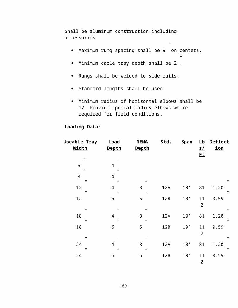
Appendices
115

APPENDIX A
Glossary of Cabling and Telecommunications Terms and Concepts
AEC – Architects, Engineers, and Consultants.AMERICAN NATIONAL STANDARDS INSTITUTE (ANSI) - ANSI is the umbrella organization in the United States for the repository and definition of standards. ANSI represents the U.S. in the International Standards Organization (ISO).
AMERICAN WIRE GAUGE (AWG) - The standard gauge for measuring the diameter of copper, aluminum, and other conductors.
ANSI/EIA/TIA 568 - Approved in 1991, this document specifies the standards for commercial building telecommunications cabling in North America. The standard specifically addresses the type of cabling to use, cabling practices, terminations and connections, and cable performance standards. The current version of this standard is the ANSI/TIA/EIA-568-B series and addenda.
ANSI/EIA/TIA 569 - North American commercial building standard for telecommunications pathways and spaces. Its purpose is to standardize specific design and construction practices within and between buildings which are in support of telecommunications media and equipment. The current version of this standard is ANSI/TIA/EIA-569-B-2004.
ASYNCHRONOUS TRANSFER MODE (ATM) - A high speed cell-based switching and multiplexing technology based on segmentation of voice, data and video into fixed packets (cells).
ATTENUATION - A reduction in strength or deterioration of an electrical signal as it passes through a transmission medium. Attenuation generally increases with frequency, cable length and the number of connections in a circuit. Attenuation is measured in decibels (dB). In optical fiber, a diminution of the signal as a function of length traveled.
AUTOTEST - A pre-programmed series of tests and pass/fail criteria used by a hand-held cable test device to determine and certify the category of performance of data cabling.
BACKBONE - The part of a premises distribution system that carries the heaviest traffic. Includes a main cable route and facilities for supporting the cable from the MC to IC, IC to HC, or ER to MC, IC, or TR.
BANDWIDTH - In electrical transmission systems, the range between the highest and lowest frequencies of a transmission channel. A measure of the information capacity of the transmission channel. The measured difference at some Frequency between Cross-talk and Attenuation. Bandwidth varies with the type and method of transmission. Bandwidth is measured in Hertz.
BARRIER - A permanent partition installed in a cable raceway or housing that
116

provides complete separation of the adjacent compartment.
BASEBAND - A network in which the entire bandwidth of the transmission medium is used as a single digital signal.
BEND RADIUS - The radius a cable can bend before the risk of breakage or increase in attenuation occurs. Or, the allowable radius a cable can be bent per a particular Standard.
BER - Bit Error Rate is calculated as follows: The data packet sent, minus the data packet received, divided by the data packet transmitted.
BICSI - Building Industry Consulting Services International. BICSI, a not-for-profit telecommunications association, is a world-wide resource for technical publications, training, conferences, and registration programs for information transport design and installation.
BIT - A contraction of the term binary digit. A bit can be either 0 or 1 and is the smallest possible unit of information in digital code.
BIT/S (BPS) - Bits per second. A measure of speed or data rate. Often combined with metric prefixes such as Kbps (kilo or thousands of bits per second) and Mbps (mega or millions of bits per second).
BNC - A bayonet-locking connector used to terminate coaxial cables. There is some disagreement as to whether BNC is an acronym for Bayonet-Neill-Concelman or Bayonet Nut Coupler.
BONDING - The permanent joining of metallic parts to form an electrically conductive path that will assure electrical continuity and the capacity to conduct safely any current likely to be imposed on it.
BROADBAND - A network in which the bandwidth can be shared by multiple simultaneous signals that are encoded with radio frequency modulations.
BUFFER COATING - Protective material applied to optical fibers.
BUILDING ENTRANCE FACILITY - The area inside a building where telecommunications cables enter and leave (see Telecommunications Entrance).
BUS - 1) A data path shared by many devices. 2) A linear network topology in which all workstations are connected to a single cable. On a bus network, such as Ethernet, all workstations receive all transmissions; only the workstation that the information is addressed to will use the information.
BYTE - A collection of bits operated upon as a unit, usually 8 bits long. Often used to represent one character. Also used to measure the capacity of storage devices.
CABLE - A bound or sheathed group of mutually insulated conductors.
CABLE TESTER - A handheld electronic device that is used to measure the electrical and
117

physical properties of network cabling. Used commonly to certify cabling to known standards, or as a troubleshooting tool.
CAMPUS - A premises containing more than one building adjacent or near to one another.
CAMPUS BACKBONE CABLE - The communications cable that is part of the Campus Backbone Subsystem and that is placed between buildings. There are four methods of installing campus backbone cable: in-conduit (in underground conduit), direct-burial (in trenches), aerial (on poles), and in-tunnel (in steam tunnels).
CAPACITANCE - The property of a system of conductors and dielectrics that permits the storage of electrically separated charges when potential differences exist between the conductors.
CATEGORY OF PERFORMANCE – Copper cable and connector hardware components, as well as link and channels, are rated to performance categories as defined by TIA. The ANSI/TIA/EIA 568-B series of standards defines the categories of performance for new construction.
CATV (COMMUNITY ANTENNA TELEVISION) - A method of delivering high quality television reception by transmitting signals from a central antenna throughout the community via coaxial cable. CATV is a broadband transmission facility which generally uses a 75W coaxial cable to carry numerous frequency-divided TV channels simultaneously.
CCTV (CLOSED CIRCUIT TELEVISION) - In general, a video channel which is broadcast to a limited number of locations. Often used in security applications.
CHANNEL – The end-to-end transmission path from equipment cable end in the TR to the patch cable end in the WA. Per ANSI/TIA/EIA 568-B.1 the Channel includes up to 328’ of horizontal cable; a work area cable; a telecommunications outlet or connector; an optional transition point or consolidation connector; and two connection (cross-connect) connected by a patch cable and an equipment cable in the telecommunications room. When a maximum horizontal length of 328’ is used, then the total length of the equipment cable, patch cable and work area cable shall not exceed 33’.
CHARACTERISTIC IMPEDANCE - The impedance that an infinitely long transmission line would have at its input terminal. If a transmission line is terminated in its characteristic impedance, it will appear (electrically) to be infinitely long, thus minimizing signal reflections from the end of the line.
CIRCUIT - 1) (Communications) A bi-directional communications path between two pieces of associated equipment. 2) (Power) An arrangement of conductors, devices and utilization equipment (loads) such that current will pass through them.
CLADDING - The material surrounding the core of a optical fiber cable. The cladding must have a lower index of refraction than the core in order to contain the light in the core.
CLOSED ARCHITECTURE - An architecture that is compatible only with hardware and software from a single vendor. Contrast with Open Architecture.
118

COAXIAL CABLE - A type of communication transmission cable in which a solid center conductor is surrounded by an insulating spacer which in turn is surrounded by a tubular outer conductor (usually a braid, foil or both). The entire assembly is then covered with an insulating and protective outer layer. Coaxial cables have a wide bandwidth and can carry many data, voice and video conversations simultaneously. Commonly used for Cable TV (CATV) or older computer networks.
CONDUIT - A rigid or flexible metallic or nonmetallic raceway of circular cross section in which cables are housed for protection and to prevent burning cable from spreading flames or smoke in the event of a fire.
CONNECTOR – A device that connects wire or fiber in cable to equipment, other wires or fibers. A receptacle used with a plug to make electrical connection between communication circuits. Connectors are considered the female component of a connector/plug connector. Connectors are typically used at the work area.
CONNECTING BLOCK - A plastic block that houses metal cabling terminals to provide a connection between two groups of wires. Connecting blocks have Insulation Displacement Connectors so insulation removed prior to termination is not required. Major block types are 110 and 66.
CONSOLIDATION POINT - An interconnection between horizontal cables that extends from building pathways to the work area, typically used to support frequent rearrangement of open office furniture clusters.
CORE - The central region of an optical fiber through which light is transmitted.
CROSS CONNECT - A facility enabling the termination of cable elements and their interconnection and/or cross-connection, primarily by means of a patch cable or jumper.
CROSS CONNECTION - A connection scheme between cabling runs, subsystems, and equipment using patch cables or jumpers that attach to connecting hardware on each end.
CROSSTALK - The phenomenon in which a signal transmitted on one circuit or channel of a transmission system creates an unwanted signal in another circuit or channel, generally related to wire placement, shielding, and transmission techniques. Crosstalk interferes with the desired data signal. The level of unwanted crosstalk in network cabling can be determined by the use of handheld testers.
DECIBEL (dB) - A unit for measuring the relative strength of a signal. Usually expressed as the logarithmic ratio of the strength of a transmitted signal to the strength of the original signal. A 3 dB increase in signal strength is twice the original signal. A 3 dB decrease is half the original signal.
DELAY - In data communications, the time between transmission and reception of a signal. Usually expressed in nanoseconds. Also see Propagation Delay.
DELAY SKEW - The difference in time between the arrival (reception) of a data signal and subsequent related data signals. Usually expressed in nanoseconds.
119

DEMARCATION - A point at which two services may interface and identify the division of responsibility, such as the point of interconnection between telephone company facilities and the user’s terminal equipment.
DUPLEX - Simultaneous bi-directional transmission over the same wire pair.
EIA (ELECTRONIC INDUSTRIES ASSOCIATION) - A consultative group of manufacturers recognized as the standards writing group in the United States for electronic equipment.
ELFEXT - Equal Level Far End Crosstalk; a measure of the unwanted signal coupling, expressed in dB relative to the received (attenuated) signal level, from a transmitter at the far end into the neighboring pairs measured at the near end. Characterizing ELFEXT is important for cabling links intended to support 4 pair, full-duplex network transmissions.
EMI/RFI (ELECTROMAGNETIC INTERFERENCE/RADIO FREQUENCY INTERFERENCE) - The interference in signal transmission or reception resulting from the radiation of undesirable electrical or magnetic fields.
ENTRANCE FACILITY - The Entrance Facility is an entrance to the building for both public and private network service cables, including the entrance point at the building wall and continuing to the entrance room or space.
EQUIPMENT ROOM (ER) - An Equipment Room is a centralized space for housing telecommunications equipment. It is differentiated from the Telecommunications Room by the type of equipment used and the room serves a building or multiple buildings in a campus environment.
ETHERNET - A baseband local area network used for connecting computers and terminals, etc., within the same building. Ethernet was marketed (and trademarked) by Xerox and developed jointly by Digital Equipment Corporation, Intel and Xerox. It is the basis for the IEEE Standard 802.3. It employs CSMA/CD as the network access method, and is popularly deployed as 10BASET, 100BASET, and 1000BASET, where 10, 100, or 1000 is the data transfer rate in megabits/second, BASE indicates Baseband transmission, and T signifies Twisted Pair as the medium.
FAR END CROSSTALK (FEXT) - Measure of unwanted signal coupling from a transmitter at the far end into neighboring pairs measured at the near end.
FERRULE - A component of a optical fiber connection that aligns and protects the stripped end of a fiber.
FIBER LOSS (Optical Loss) - The attenuation (decrease) of the light signal in optical fiber transmission. Optical loss is directly related to the length of fiber and the quality and number of connections and splices in a fiber segment.
FIRE-RATED POKE-THROUGH - A cable distribution device which is fitted through a pre-drilled core hole in the floor and allows cables to be fed from the floor below.
FLOOR BOX - A cast iron, stamped steel or nonmetallic box placed in the concrete floor
120

(prior to pouring the concrete slab) of a building which is fed via conduit and used to house voice, data, power and video connections.
FULL DUPLEX - Simultaneous bi-directional signal transmission.
FURNITURE CLUSTER - A contiguous group of personal work areas, usually constructed from furniture, typically including partitions of other space division, work surfaces, storage and seating. The work area cluster does not span aisles; all components are in contact or close proximity.
GSFIC - Georgia State Finance and Investment Commission
GTA – Georgia Technology Authority.
GHz (GIGAHERTZ) - A unit of frequency equal to one billion Hertz (1,000,000,000 Cycles per Second).
GROUNDING CONDUCTOR - The conductor used to connect the grounding electrode to the building’s main grounding busbar.
GROUNDING ELECTRODE - A conductor of a group of conductors (usually a rod, pipe or plate) in direct contact with the earth providing a low impedance connection to the earth.
HALF DUPLEX - A circuit which provides transmission alternately in either direction.
HEADROOM - The number of decibels by which a system exceeds the minimum defined requirements.
HERTZ (Hz) - A unit of frequency or bandwidth equal to one cycle per second.
HOME RUNS - A pathway or cable between two locations without a point of access in between. Characterized in Star Topologies.
HORIZONTAL CABLING - The cabling between and including the telecommunications outlet/connector and the horizontal cross connect.
HORIZONTAL CROSS CONNECT (HC) - A cross connect of horizontal cabling to other cabling, i.e., horizontal, backbone, equipment.
HUB - Connection point for circuits or a network. Hubs may be active or passive
HYBRID CABLE - An assembly of 2 or more cables of the same or different types or categories covered by one overall sheath.
IEEE - Institute of Electrical and Electronics Engineers.
IMPEDANCE - A unit of measure, expressed in Ohms, of the total opposition (resistance, capacitance and inductance) offered to the flow of an alternating current.
INFRASTRUCTURE, TELECOMMUNICATIONS - A collection of those telecommunications components, excluding equipment that together provides the basic
121

support for the distribution of all information within a building or campus.
ISO - International Standards Organization. The body which promotes the development of worldwide standards.
INSERTION LOSS - The reduction in the amount of power received before and after the insertion of a component (i.e., connector, coupler or splice) into a previously continuous transmission line. Optical fiber insertion loss is referred to as ‘power loss’.
INSULATION DISPLACEMENT - A type of wire terminal that requires no wire stripping; when the wire is correctly attached, its insulation is displaced (pierced) to form a connection. A popular form of insulation displacement termination is the 110 system.
INTERCONNECTION - A connection scheme that provides for the direct connection of a cable to another cable or to an equipment cable without a patch cable or jumper.
INTERMEDIATE CROSS CONNECT (IC) - A cross connect between first level and second level backbone cabling.
ISDN - Switched network providing end-to-end digital transparency transmitting voice and data over the same transmission facilities.
JACKET - The flexible covering of a cable, used to protect the color-coded conductors inside. Also referred to as a cable's "sheath".
JUMPER - An assembly of two twisted wires without connectors used to join telecommunications circuits/links at the cross connect.
LEC (LOCAL EXCHANGE CARRIER) - A private communications utility company or a government organization that furnishes services to the general public. It is typically licensed or regulated by a state or federal government agency.
LED (LIGHT EMITTING DIODE) - A semiconductor diode which emits light when a current is passed through it. In lightwave transmission systems, LEDs or lasers are used as light sources.
LINK - The link is regarded as the permanent portion of the cabling system. A test configuration for the link consists of up to 90m (295’) of horizontal cabling, a telecommunications outlet/connector, and up to two cross connect connections in a telecommunications room. The link specifically excludes patch cables and equipment cables.
LOCAL AREA NETWORK (LAN) - A non-public data communications network confined to a limited geographic area used to provide communication between computers and peripherals.
LOOPBACK - A type of diagnostic test in which a transmitted signal is returned to the sending device after passing through a data communications link or network. This test allows the comparison of a returned signal with the transmitted signal.
122
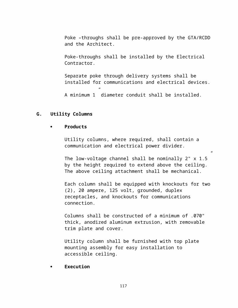
LOSS - Reduction in signal strength, expressed in decibels (dB). Opposite of gain.
MAIN CROSS CONNECT (MC) - A cross connect for first level backbone cables, entrance cables, and equipment cables.
MHz (MEGA HERTZ) - A unit of frequency equal to one million Hertz (1,000,000 Hertz).
METROPOLITAN AREA NETWORK (MAN) - An extended LAN operating within a metropolitan area and provides an integrated set of services for real-time data, voice and image transmission.
MICRON - A unit of length equal to one millionth of a meter (.000001 meter). Short for micrometer.
MIPS - Millions of instructions per second. A measure of processing power.
MODEM (MODULATOR DEMODULATOR) - A device which converts digital signals to analog signals (and vice-versa) for transmission over the telephone network, which usually is analog.
MT-RJ - A small form factor fiber connector that features a high-density design and RJ45 locking mechanism.
MULTIFIBER CABLE - An optical fiber cable containing two or more fibers, each providing a separate information channel.
MULTIMEDIA - A means of conveying information with components in different media such as voice, music, text, graphics, image and video.
MULTIMODE OPTICAL FIBER - An optical fiber that will allow many bound modes to propagate. The fiber may be either a grade-index or step-index fiber. Typically used in premise environments only. Multimode Fiber cores are typically either 62.5 or 50 microns in diameter. See Single Mode Fiber.
MUTOA - A Multi-User Telecommunications Outlet Assembly, used to facilitate furniture rearrangement in open office areas. Defined by ANSI/TIA/EIA 568B-1.
NANOSECOND (NS) - One billionth of a second.NATIONAL ELECTRICAL CODE (NEC) - A nationally recognized safety standard for the design, construction, and maintenance of electrical circuits.NETWORK - A formalized definition of the structure and protocols of a computer network.
NETWORK INTERFACE - The point of interconnection between telephone company communications facilities and terminal equipment, protective apparatus or cabling at a subscriber’s premises.
NEXT (NEAR END CROSSTALK) - Electrical noise coupled from different wire pairs within a common sheath.
NODE - In general, any point of interconnection to a network where service is provided,
123

used or communication channels are interconnected.
NOISE - Random electrical signals, introduced by circuit components or natural disturbances, which degrade the performance of a communication channel.
OPEN ARCHITECTURE - An architecture that is compatible with hardware and software from any of many vendors.
OPEN OFFICE - An office which a floor space division is provided by furniture, furniture partitions, or both instead of by building walls.
OPEN SYSYTEM INTERCONNECTION (OSI) - An internationally accepted framework of standards developed by the International Standards Association, for communication between two systems made by different vendors.
OPTICAL FIBERS - The technology in which communication signals in the form of modulated light beams are transmitted over a glass or plastic fiber transmission medium, and then demodulated to electrical signals by a light sensitive receiver.
OPTICAL TIME-DOMAIN REFLECTOMETER (OTDR) - An instrument that characterizes cable loss by measuring the backscatter and reflecting of injected light as a function of time. It is most useful for locating splices, connections, and breaks. It is not as useful as a Optical fiber Test Set for accurately measuring cable attenuation, and shall therefore not be used to certify an optical link.
PASSIVE EQUIPMENT - Components and/or equipment that pass active signals without conversion.
PATCH CABLE - A short length of copper or optical fiber cable with connectors on each end used to join communications circuits as a cross connect.
PATCH PANEL - A cross connect system of mateable connectors, utilizing patch cables, that facilitates administration.
PATHWAY - A facility for the placement of telecommunications cable.
PEDESTAL - A device usually mounted on the floor, which is used to house voice/data jacks or power outlets at the point of use.
PERSONAL COMPUTER (PC) - A computer for personal, single-user use, as opposed to main frames or minicomputers which are shared by many users.PERMANENT LINK - The transmission path between two mated interfaces of cabling, excluding equipment cables, work area cables and cross-connections.PHYSICAL LAYER - Within the OSI Model, the lowest level (Level 1) of network processing, below the link layer, concerned with the electrical, mechanical, and handshaking procedures over the interface that connects a device to a transmission medium.
PLENUM – In building construction, the space that is used for air circulation in heating and air conditioning systems, typically between the structural ceiling and the suspended ceiling
124

or under a raised floor. The plenum space is often used to house the communication cables for the building's telecommunications network... In those instances, Plenum cable must be used.
PLENUM CABLE - Plenum cable is coated with a fire-retardant coating (usually Teflon) so that in case of a fire it does not give off toxic gasses and smoke as it burns. Required for cables used in plenum areas.
PLUG - The male component of a connection. It is typically used on one or both ends of equipment cables or on cabling for interconnect or cross connect.
POINT TO POINT TRANSMISSION - An uninterrupted connection between two pieces of equipment.
PORT - A functional unit of a node through which data can enter or leave a data network...
POWER METER – The most effective tool to measure light loss in a optical fiber link. Typically used to describe a test set used to accurately measure optical loss in a optical fiber link. Comprised of a light source, capable of injecting light at different frequencies into the fiber link; and the power meter itself, which when properly calibrated will display the amount of optical loss for that link.
POWER/COMMUNICATIONS POLE - A raceway placed between the ceiling and floor used in conjunction with a ceiling distribution system for the purpose of distributing communication and power service to a work area. Also called Utility Pole, Service Pole or Tele-power Pole.
POWERSUM CROSSTALK - A measure of the combined crosstalk on a receive pair from all near end disturbers operating simultaneously.
PREMISES CABLING - The entire cabling system on the user’s premises used for transmission of voice, data, video and power.
PRINTED CIRCUIT - A copper foil circuit formed on one or both faces of an insulating board to which circuit components are soldered. The copper foil pattern serves to connect components and is produced either by etching or plating.
PRIVATE BRANCH EXCHANGE (PBX) - A private telephone switching system, usually located on a customer’s premises connecting a common group of lines from one or more central offices to provide service to a number of individual phones. Now used interchangeably with PABX (Private Automatic Branch Exchange).
PROPAGATION DELAY - The time it takes for a signal to travel from one point on a circuit to another.
PROTOCOL - A formal set of conventions governing the format and control of inputs and outputs between two communication devices or processes.
PVC - Polyvinyl Chloride. A type of plastic commonly used for cladding telecommunications cable.
125

PUBLIC SWITCHED NETWORK - Any common carrier network that provides circuit switching between public users, such as the public telephone network, telex or MCI’s Execunet.
RACEWAY - Any channel designed for holding wires, cables or busbars such as conduit, surface raceways, cellular floors or cable troughs.
RBOC (REGIONAL BELL OPERATING COMPANY) - One of the seven Bell operating companies that were formed during the divestiture of AT&T.
RCDD - The Registered Communications Distribution Designer is a professional engineering status granted by BICSI based on knowledge of the telecommunications cabling industry.
REPEATER - In digital transmission, equipment that receives a pulse train, amplifies it, re-times it, and then reconstructs the signal for retransmission.
RETURN LOSS - The measure of the reflected energy caused by impedance mismatches in a cabling system.
RISER - The conduit or path between floors of a building into which telephone and other utility cables are placed to bring service from one floor to another.
RJ (REGISTERED JACK) - Registered Jack (RJ) cabling configurations developed by the Bell System for connection of customer premises equipment to the public network. Registered jacks serve telephone and data applications and are registered with the FCC. The most common types are: RJ45 and RJ11.
SC - Designation for an optical connector featuring a 2.5mm physically contacting ferrule with a push-pull mating design. This connector is recommended in the ANSI/TIA/EIA-568B-1 Standard for structured cabling.
SFF (SMALL FORM FACTOR) - A ANSI/TIA/EIA approved fiber adapter/connector system that provides two fiber strands in a surface area similar to UTP (RJ-style) connection.
SHIELD (SCREEN) - A metallic layer usually in the form of a braid or foil surrounding one or more electrical conductors to insulate them from electromagnetic interference.
SINGLEMODE OPTICAL FIBER - An optical fiber that will allow only one mode to propagate. This fiber is typically a step index fiber and typically has a core diameter of 8.3 microns.
SLEEVES - Short lengths of rigid metal pipe, approximately 4 in. (10.1 cm) in diameter, located in the telecommunications room (TR), which allow cables to pass from floor to floor when TRs are vertically aligned. Sleeves also provide for easy pulling of cable.
SLOTS - Openings in the floor of riser telecommunications closets that allow cables to pass thorough from floor to floor when closets are vertically aligned. A slot accommodates more cables than an individual sleeve.
126

SPLICE - The joining of two or more cables by connecting the conductors pair to pair. Not allowed with twisted pair cables per the 568B Standard.
ST - Designation for the “straight tip” connector developed by AT&T. This optical connector features a physically contacting non-rotating 2.5mm ferrule design and bayonet connector-to-adapter mating.
STAR - A physical point to point network topology.
STRUCTURED CABLING SYSTEM - A telecommunications cabling system, capable of supporting a wide range of applications. Generic cabling can be installed without prior knowledge of the required applications. Application-specific hardware is not a part of generic cabling.
SUBMINATURE D CONNECTOR - A family of multi-pin data connectors used in RS232-C communications. The connectors are available in 9, 15, 25 and 37 pin configurations. Sometimes referred to as DB9, DB15, DB25 and DB37 connectors respectively.
SURGE SUPPRESSION - The process by which transient voltage surges are prevented from reaching sensitive electronic equipment.
SURFACE RACEWAY - A cable distribution method in which channels containing cables are run along or within the baseboards of a building.
SWITCHING - A function carried out by a switching hub, alleviating traffic by making virtual connections between transmitting and receiving nodes.
T1 - A digital transmission link with 1.544 Mbps bandwidth. T1 operates on two twisted pairs and can handle 24 voice conversations, each digitized at 64 Kbps. More voice channels are available with advanced digital voice encoding techniques.
T1 CARRIER - The AT&T digital transmission system which transmits data at 1.544 Mbps (See also T1).
TELECOMMUNICATIONS - For the purposes of this Glossary, a term encompassing voice, audio/visual, and data communications in the form of coded signals transmitted over media.
TELECOMMUNICATIONS OUTLET - A device where the horizontal cable terminates in the Work Area (WA). The telecommunications outlet provides the interface to the work area cabling.
TELECOMMUNICATIONS ROOM (TR) - A Telecommunication Room is an enclosed space for housing telecommunications equipment, cable terminations and cross-connect cabling. Typically, this room is used as the location of the horizontal cross-connect and serves a floor.
TELECOMMUNICATIONS ENTRANCE - The point where telecommunications lines enter or leave the building.
127

TERMINATION - The act of attaching connectors to bare cabling. In the case of data cabling, terminations must be in accordance with standard cabling codes and standards.
TOPOLOGY - The geometric description of the physical or logical connections of a telecommunications system. Typically described as bus, ring or star.
TRANSCEIVER - A single device capable of both sending and receiving information.
TRANSIENT - An abrupt change in voltage, of short duration, which may cause signal impairments, loss of memory or physical damage to equipment.
TRANSMISSION MEDIA - Anything such as wire, coaxial cable, optical fibers, air or vacuum, that is used to carry an electrical signal.
TRUNK - A specialized communications path between two points, one of them usually being a telephone company central office or switching center.
TWISTED PAIR CABLE - A type of communication transmission cable in which two individually insulated wires are twisted around each other to reduce induction (thus interference) from one wire to the other. The pair may be surrounded by a shield, insulating jacket or additional pairs of wires.
USOC - Universal Service Ordering Codes (USOC) are a series of Registered Jack (RJ) cabling configurations developed by the Bell System for connection of customer premises single line equipment to the public network.
UTP – Unshielded twisted pair copper cable.
WAVELENGTH - The length of an electromagnetic waveform as measured from any point on one wave to the corresponding point on an adjacent wave, such as from crest to crest. Wavelength is inversely proportional to frequency.
WIDE AREA NETWORK (WAN) - A communications network designed to serve hundreds or thousands of miles using common carrier-provided lines, such as the nationwide telephone network. Compare with LAN.
WIDEBAND - A communications channel or medium having a bandwidth sufficient to carry multiple voice/video or data signals simultaneously.
WIRE – A single copper conductor/wire covered with a plastic jacket.
WORK AREA / WORK STATION (WA) - A building space where the occupants interact with telecommunications equipment.
128

APPENDIX B - REFERENCES Codes and Standards
• Federal Aviation Administration FCC Docket 21006— Frequency Accuracy. Washington, D. C.: Federal Aviation Administration.
• Federal Communications Commission Code of Federal Regulations (CFR) — 10CFR47, Part 76.605.
• Signal Quality for CATV Washington, D. C.: Federal Communications Commission.
• Institute of Electrical and Electronics Engineers, Inc. Standards and Guidelines New York: Institute of Electrical and Electronics Engineers, Inc.
• National Fire Protection Association, Inc. National Electrical Code ® 1999 ed. Quincy, Mass.: National Fire Protection Association, Inc., 1998.
• Publications and Industry Standards Exton, Penn.: Society for Cable Telecommunications Engineers, Inc.
• ANSI/ TIA/ EIA- 492AAAB Detail Specification for 50 µm Core Diameter/ 125 µm Cladding Diameter Class 1a Multimode, Graded- Index Optical Wave guide Fibers Arlington, Va.: Telecommunications Industry Association/ Electronic Industries Alliance, November 1998.
• NSI/ TIA/ EIA- 492CAAA Detail Specification for Class IVa Dispersion— Unshifted Single- Mode Optical Fibers. Arlington, Va.: Telecommunications Industry Association/Electronic Industries Alliance, May 1998.
• ANSI/ TIA/ EIA- 568B. Commercial Building Telecommunications Cabling Standard Arlington, Va.: Telecommunications Industry Association/ Electronic Industries Alliance, October 1995.
• ANSI/ TIA/ EIA- 569A A. Commercial Building Standard for Telecommunications Pathways and Spaces Arlington, Va.: Telecommunications Industry Association/Electronic Industries Alliance, February 1998.
• ANSI/ TIA/ EIA- 606A Administration Standard for the Telecommunications Infrastructure of Commercial Buildings Arlington, Va.: Telecommunications Industry Association/Electronic Industries Alliance, February 1993.
• ANSI/ TIA/ EIA- 758 Customer- Owned OSP Telecommunications Cabling Standard. Arlington, Va.: Telecommunications Industry Association/ Electronic Industries Alliance, February 1999. Telcableia Technologies, Inc. (Bellcore). TR- TSY- 000100 Issue Bulletin. Morristown, N. J.: Telcableia Technologies, Inc. Replaced by GR- 421- CORE, Generic Requirements for Metallic Telecommunications Cables, December 1998.
129

• TR- TSY- 000107 Issue 2 Bulletin. Morristown, N. J.: Telcableia Technologies, Inc. Replaced by GR-421- CORE, Generic Requirements for Metallic Telecommunications Cables, December 1998.
• American National Standards Institute. ANSI T1.311. American National Standard for Telecommunications — DC Power Systems— Telecommunications Environmental Protection New York: American National Standards Institute, 1998.
• ANSI T1.313. American National Standard for Telecommunications— Electrical Protection for Telecommunications Central Offices and Similar Type Facilities. New York: American National Standards Institute, 1998.
• ANSI/ IEEE Standard 142. Recommended Practice for Grounding of Industrial and Commercial Power Systems. New York: Institute of Electrical and Electronics Engineers, Inc., 1991. Also known as the IEEE Green Book.
• ANSI/ IEEE Standard 241. Recommended Practices for Electrical Power Systems in Commercial Buildings. New York: Institute of Electrical and Electronics Engineers, Inc., 1990. Also known as the IEEE Gray Book.
• ANSI/ IEEE Standard 446. Recommended Practice for Emergency and Standby Power Systems for Industrial and Commercial Applications. New York: Institute of Electrical and Electronics Engineers, Inc., 1987. Also known as the IEEE Orange Book.
• ANSI/ IEEE Standard 1100 Recommended Practice for Powering and Grounding Sensitive Electronic Equipment in Industrial and Commercial Power Systems New York: Institute of Electrical and Electronics Engineers, Inc., 1999. Also known as the IEEE Emerald Book.
• American National Standards Institute/ National Fire Protection Association, Inc. ANSI/NFPA- 70 National Electrical Code ®. Quincy, Mass.: National Fire Protection Association, Inc., 1999.
• American National Standards Institute/ Telecommunications Industry Association/ Electronic Industries Alliance
• ANSI/ TIA/ EIA- 607 Commercial Building Grounding and Bonding Requirements for Telecommunications. Arlington, Va.: Telecommunications Industry Association/Electronic Industries Alliance, August 1994.
130

Selected Guidelines
Argonne National Laboratory, Electronics and Computing Technologies Division, Specifications for OSP Telecommunications Facilities, “Installation of Copper and Optical fiber Cable Systems”, November 1997, http://www.ect.anl.gov/telecommunications/outsideplantspecs.htm
Bucknell University, “Cabling Specifications, Section 17100 – Network Communications Systems”, June 1998http:// www.isr.bucknell.edu/network/powerpoint/cablingspecifications
The University of California Irvine, Network and Academic Computing Services, Network and Telephone Services, “Project Planning Guidelines”, June 2000
California State University, “Telecommunications Infrastructure Planning Guidelines”, http://www.calstate.edu/tier3/PPD/AE/Design_STDS.html.
The University of Chicago, “Structured Cabling Specifications, Universal Cabling Plan”, September 2000
The University of Connecticut, “Telecommunications Design Guide and Standards”, http://www.comm.uconn.edu/tscontents.htm
East Carolina University, “Telecommunications Standards”, June 2001
Emory University, “General Building Specifications for NetCom, Communications Standards”, December 2000
The University of Florida, Physical Plant Division, “Telecommunications Construction Standards”, August 2001, http://ppd.ufl.edu/telecommunications/telecom-construction.html
The University of Georgia, Policy 33.4, “Cabling Specifications for Telephone, Data and Video Services”, http://www.uga.edu/netinfo
The Board of Regents of the University System of Georgia, “Facilities Guidelines for Instructional Technology”, December 2001
Houston Independent School District, Offices of Technology and Information Services, “HISD Network Cabling Standards”, , January 2000, http://dept.houstonisd.org/technology/hisd%20network%
Indiana University Southeast, “Technical Standards for Telecommunications Distribution Facilities”, June 1993
131
The University of Kentucky, Communication and Network Systems, “Telecommunications Standards”, Revision 4.0, January 2002
The State of Minnesota, Inter Technologies Group, Building Infrastructure Standards for State Owned Buildings, September 2000
The State of North Carolina, State Telecommunications Services, “STS-1000 Telecommunications Cabling Guidelines”, http://www.its.state.nc.us/about/divisions/ITS/Forms/STS1000.pdf
Commonwealth of Virginia, Department of Technology Planning, Information Technology Resource Management, “Networking, Telecommunications and Cabling Standard”, http://www.cim.state.va.us/pubs/standards/ NET2001-01-1- NetworkingTelecommunicationsAndCablingStandard.doc
Oakland Unified School District, Research and Development Laboratory for Learning Technologies (Technology Services Department), “System Installation and Cabling Guide”, January 2, 2001, http://webtest.ousd.k12.ca.us/svrapps/ousdgs/default.asp
Sacramento Municipal Utility District, “Electric Service Requirements, Section V, Customer-Owned Service Poles, Engineering Specification T005”, August 2001
The State of Washington, Department of Information Services, “Architecture Standards, Computing and Telecommunications”, http://www.wa.gov/dis/portfolio/computingandtelecommstands.htm, December 2000
The University of Waterloo, Waterloo Canada, “Cable Plant Procedures and Guidelines”, Rev 2.0, December 2001
Other Reference Sources
Building Industry Consulting Service International (BICSI) - Telecommunications Distribution Method Manual (TDMM)
BICSI Customer Owned OSP Manual
BICSI Cabling Installation Manual
BICSI LAN Design Manual
Telecommunication Industry Association (TIA) - Telecommunications standards
Underwriters Laboratory (UL) - Testing organization (safety)
Occupational Safety and Health Administration (OSHA) – Worker Safety
132
National Electric Code (NEC) – Intrabuilding electrical safety
National Electric Safety Code (NESC) - Interbuilding electrical safety
Building Industry Consulting Service International (BICSI) - Telecom trade association & developer of TDM manuals
American National Standards Institute (ANSI) - Standards
American Insurance Association (AIA) - Insurance standards for buildings and infrastructure
Insulated Cable Engineers Association (ICEA) - Manufacturer’s organization that writes specifications for cable
Building officials and Code Administration (BOCA) - Building Codes
National Fire Protection Association (NFPA) - Fire safety codes
National Institute of Standards and Technology (NIST) - Technology Standards
ATM Forum - Standards body for ATM standards
International Organization for Standards (ISO) - Produces standards documents
Institute of Electrical and Electronics Engineers (IEEE) - Electronics, Telecom, and Electrical standards
Federal Communications Commission (FCC)
The Americans Disabilities Act (ADA) - Federal Regulation
Bell Operations and Construction Standards (BOCS) - Outside/Entrance Plant/USOC
AT&T Plant Standards - Outside/Entrance Plant
Rural Utilities Services Specifications (RUS) - PE_89 OSP Cable
133

APPENDIX C
GTA RCDD CONTACT INFORMATION
Glenn Bishop, RCDD, LVLCRegional Engineer – South229-430-7808E-mail: [email protected]
Daryl Seay, RCDD, LVLCRegional Engineer – North West 404-756-4048E-mail: [email protected]
Adrian Whitaker, RCDD, LVLCRegional Engineer – North East404-756-4752E-mail: [email protected]
134

Appendix DCSI Master Format and Sample Specifications
CSI Master Format 2004Division 27
Information within the following sections of Division 27 shall be used where appropriate or expanded upon and additional sections included as deemed appropriate by the Designer.
DIVISION 27 – COMMUNICATIONS27 00 00 COMMUNICATIONS27 01 00 Operation and Maintenance of Communications Systems27 01 10 Operation and Maintenance of Structured Cabling and Enclosures27 01 20 Operation and Maintenance of Data Communications27 01 30 Operation and Maintenance of Voice Communications27 01 40 Operation and Maintenance of Audio-Video Communications27 01 50 Operation and Maintenance of Distributed Communications and Monitoring27 05 00 Common Work Results for Communications27 05 13 Communications Services27 05 13.13 Dialtone Services27 05 13.23 T1 Services27 05 13.33 DSL Services27 05 13.43 Cable Services27 05 13.53 Satellite Services27 05 26 Grounding and Bonding for Communications Systems27 05 28 Pathways for Communications Systems27 05 28.29 Hangers and Supports for Communications Systems27 05 28.33 Conduits and Backboxes for Communications Systems27 05 28.36 Cable Trays for Communications Systems27 05 28.39 Surface Raceways for Communications Systems27 05 43 Underground Ducts and Raceways for Communications Systems27 05 46 Utility Poles for Communications Systems27 05 48 Vibration and Seismic Controls for Communications Systems27 05 53 Identification for Communications Systems27 06 00 Schedules for Communications27 06 10 Schedules for Structured Cabling and Enclosures27 06 20 Schedules for Data Communications27 06 30 Schedules for Voice Communications27 06 40 Schedules for Audio-Video Communications27 06 50 Schedules for Distributed Communications and Monitoring27 08 00 Commissioning of Communications
135

27 10 00 STRUCTURED CABLING27 11 00 Communications Equipment Room Fittings27 11 13 Communications Entrance Protection27 11 16 Communications Cabinets, Racks, Frames and Enclosures27 11 19 Communications Termination Blocks and Patch Panels27 11 23 Communications Cable Management and Ladder Rack27 11 26 Communications Rack Mounted Power Protection and Power Strips27 13 00 Communications Backbone Cabling27 13 13 Communications Copper Backbone Cabling27 13 13.13 Communications Copper Cable Splicing and Terminations27 13 23 Communications Optical Fiber Backbone Cabling27 13 23.13 Communications Optical Fiber Splicing and Terminations27 13 33 Communications Coaxial Backbone Cabling27 13 33.13 Communications Coaxial Splicing and Terminations27 13 43 Communications Services Cabling27 13 43.13 Dialtone Services Cabling27 13 43.23 T1 Services Cabling27 13 43.33 DSL Services Cabling27 13 43.43 Cable Services Cabling27 13 43.53 Satellite Services Cabling27 15 00 Communications Horizontal Cabling27 15 00.16 Voice Communications Horizontal Cabling27 15 00.19 Data Communications Horizontal Cabling27 15 00.23 Audio-Video Communications Horizontal Cabling27 15 00.39 Patient Monitoring and Telemetry Communications Horizontal Cabling27 15 00.43 Nurse Call and Intercom Communications Horizontal Cabling27 15 00.46 Paging Communications Horizontal Cabling27 15 00.49 Intermediate Frequency/Radio Frequency Communications Horizontal Cabling27 15 00.53 Antennas Communications Horizontal Cabling27 15 13 Communications Copper Horizontal Cabling27 15 23 Communications Optical Fiber Horizontal Cabling27 15 33 Communications Coaxial Horizontal Cabling27 15 43 Communications Faceplates and Connectors27 16 00 Communications Connecting Cables, Devices and Adapters27 16 13 Communications Custom Cable Assemblies27 16 16 Communications Media Converters, Adapters, and Transceivers27 16 19 Communications Patch Cables, Station Cables, and Cross Connect Wire27 20 00 DATA COMMUNICATIONS27 21 00 Data Communications Network Equipment27 21 13 Data Communications Firewalls27 21 16 Data Communications Routers, CSU/DSU, Multiplexers, Codec’s, and Modems27 21 26 Data Communications Network Management27 21 29 Data Communications Switches and Hubs27 21 33 Data Communications Wireless Access Points27 22 00 Data Communications Hardware27 22 13 Data Communications Mainframes
136

27 22 16 Data Communications Storage and Backup27 22 19 Data Communications Servers27 22 23 Data Communications Desktops27 22 26 Data Communications Laptops27 22 29 Data Communications Handhelds27 24 00 Data Communications Peripheral Data Equipment27 24 13 Printers27 24 16 Scanners27 24 19 External Drives27 24 23 Audio-Video Devices27 24 26 Virtual Reality Equipment27 24 29 Disaster Recovery Equipment27 25 00 Data Communications Software27 25 13 Virus Protection Software27 25 16 Application Suites27 25 19 Email Software27 25 23 Graphics/Multimedia Software27 25 26 Customer Relationship Management Software27 25 29 Operating System Software27 25 33 Database Software27 25 37 Virtual Private Network Software27 25 39 Internet Conferencing Software27 26 00 Data Communications Programming and Integration Services27 26 13 Web Development27 26 16 Database Development27 26 19 Application Development27 26 23 Network Integration Requirements27 26 26 Data Communications Integration Requirements27 30 00 VOICE COMMUNICATIONS27 31 00 Voice Communications Switching and Routing Equipment27 31 13 PBX/ Key Systems27 31 23 Internet Protocol Voice Switches27 32 00 Voice Communications Telephone Sets, Facsimiles and Modems27 32 13 Telephone Sets27 3216 Wireless Transceivers27 32 23 Elevator Telephones27 32 26 Ring-Down Emergency Telephones27 32 29 Facsimiles and Modems27 32 36 TTY Equipment27 33 00 Voice Communications Messaging27 33 16 Voice Mail and Auto Attendant27 33 23 Interactive Voice Response27 33 26 Facsimile Servers27 34 00 Call Accounting27 34 13 Toll Fraud Equipment and Software27 34 16 Telemanagement Software
137

27 35 00 Call Management27 35 13 Digital Voice Announcers27 35 16 Automatic Call Distributors27 35 19 Call Status and Management Displays27 35 23 Dedicated 911 Systems27 40 00 AUDIO-VIDEO COMMUNICATIONS27 41 00 Audio-Video Systems27 41 13 Architecturally Integrated Audio-Video Equipment27 41 16 Integrated Audio-Video Systems and Equipment27 41 16.25 Integrated Audio-Video Systems and Equipment for Restaurants and Bars27 41 16.28 Integrated Audio-Video Systems and Equipment for Conference Rooms27 41 16.29 Integrated Audio-Video Systems and Equipment for Board Rooms27 41 16.51 Integrated Audio-Video Systems and Equipment for Classrooms27 41 16.61 Integrated Audio-Video Systems and Equipment for Theaters27 41 16.62 Integrated Audio-Video Systems and Equipment for Auditoriums27 41 16.63 Integrated Audio-Video Systems and Equipment for Stadiums and Arenas27 41 19 Portable Audio-Video Equipment27 41 23 Audio-Video Accessories27 42 00 Electronic Digital Systems27 42 13 Point of Sale Systems27 42 16 Transportation Information Display Systems27 42 19 Public Information Systems27 50 00 DISTRIBUTED COMMUNICATIONS AND MONITORING SYSTEMS27 51 00 Distributed Audio-Video Communications Systems27 51 13 Paging Systems27 51 13.13 Overhead Paging Systems27 51 16 Public Address and Mass Notification Systems27 51 19 Sound Masking Systems27 51 23 Intercommunications and Program Systems27 51 23.20 Commercial Intercommunications and Program Systems27 51 23.30 Residential Intercommunications and Program Systems27 51 23.50 Educational Intercommunications and Program Systems27 51 23.63 Detention Intercommunications and Program Systems27 51 23.70 Healthcare Intercommunications and Program Systems27 52 00 Healthcare Communications and Monitoring Systems27 52 13 Patient Monitoring and Telemetry Systems27 52 16 Telemedicine Systems27 52 19 Healthcare Imaging Systems27 52 23 Nurse Call/Code Blue Systems27 53 00 Distributed Systems27 53 13 Clock Systems27 53 16 Infrared and Radio Frequency Tracking Systems27 53 19 Internal Cellular, Paging, and Antenna Systems27 60 00 Reserved27 70 00 Reserved27 80 00 Reserved
138

27 90 00 Reserved
Sample Specifications
STATE OF GEORGIA TELECOMMUNICATIONS DESIGN MANUAL
OVERVIEW
The following information is provided to ensure that the minimum information from specific sections of the GTDM is included in all project construction Specifications. This sample specification is not intended to present a comprehensive set of Specifications for any given project. It is incumbent on the Designer and the using Agency to ensure that all applicable sections of the GTDM have been applied as relevant to each project.
Division 27 – Communications will be used as the core basis for review and acceptance of all Specifications submitted to GTA or GSFIC for approval. However, the Designer is required to apply all divisions of the latest CSI Master Format Construction Specifications (currently 2004) as they impact the Communications design and installation for each project. Therefore, any Specifications submitted that do not follow this format and/or does not include the minimum information as presented in this sample will be categorically rejected.
The submitted Specifications for review must be accompanied by the corresponding set of “T” Drawings. The drawings must also comply with the GTDM in their content and numbering scheme and shall also be consistent with the Specifications.
During the review, normally at the 80% stage, the following Sections, at a minimum, are expected to be present in the submitted Specifications.
CSI MASTER FORMAT DIVISION 27
REQUIRED DIVISION 27 SECTIONS
The Communications section of the Specifications manual shall be numbered separately and distinctly from other sections (i.e., Communications can no longer be overlaid with Electrical).
Additionally: The overall CSI Master-format Construction Drawing package shall identify Telecommunications Drawings using “T series” numbers. These drawings shall be included in addition to the other CSI Divisions if the scope of the telecommunication work justifies
139

this effort. Some drawing elements may be combined into a single sheet for smaller projects. Larger projects may require more drawings to convey the intent of the telecommunications cabling and support infrastructure design. Drawings shall be provided to address both inter-building and intra-building telecommunications needs based upon the scope of work developed during the pre-design phase of the project.
The minimum information from specific sections of the GTDM to be included in all project Specifications is as follows:
140

141

SECTION 270000 – COMMUNICATIONS
PART 1 - GENERAL
1.1 INTRODUCTION
A. The State of Georgia Telecommunications Manual, hereinafter referred to as GTDM, shall be used by State of Georgia Agencies, Architects, Design Engineers and Low Voltage Telecommunications Contractors (LVLTC) for the design and construction of all Information Transport Systems installed in State facilities. The GTDM is based upon the most current available literature, codes, standards and industry accepted practices available at the time of publication.
B. The GTDM establishes a strategic direction for the physical connection of communications devices in State of Georgia facilities. A properly designed and constructed telecommunications system shall be adaptable to change over the life of the building.
C. The design and construction of the telecommunications system shall:1. Provide telecommunications architecture based on recognized standards to support
efficient, long-lasting, cost-effective operations.2. Reduce the amount of time required to install new networks or to reconfigure
existing local area networks. 3. Provide the flexibility to operate multiple high bandwidth technologies on a single
structured cabling system.4. Eliminate the cost of installing non-standard, proprietary, vendor-specific cabling
by providing standards-based cabling systems that will support a wide variety of equipment.
5. Improve network manageability and facilitate automated cabling system management through the use of uniform and industry standard identification and numbering schemes.
6. Allow for the growth of anticipated high speed, high bandwidth Local Area Networks (LANs), Metropolitan Area Networks (MANs) and Wide Area Networks (WANs) that may be required by future specialized applications.
1.2 STANDARDS:
A. Effective telecommunications and networking cannot be accomplished without adherence to standards. Additionally cabling infrastructure costs cannot be contained without adherence to sound installation and management practices. To ensure that the future telecommunications and connectivity needs of agencies are met in a cost-effective manner, the GTDM confirms the State of Georgia’s support for ANSI/TIA/EIA and IEEE standards for telecommunications.
B. American National Standards Institute (ANSI) approves standards as having been properly developed.
C. ANSI/TIA/EIA-526, Optical Fiber Systems Test Procedures. D. ANSI/TIA/EIA-568, Commercial Building Telecommunications Cabling Standard.E. ANSI/EIA/TIA-569, Commercial Building Standard for Telecommunications Pathways and
Spaces. F. ANSI/TIA/EIA-606A, Administration Standard for the Telecommunications Infrastructure
142

of Commercial Buildings.G. ANSI/TIA/EIA-607, Commercial Building Grounding and Bonding Requirements for
Telecommunications.H. IEEE 802.3, Local Area Network Ethernet Standard.I. Building Industry Consulting Service International, Inc. (BICSI) Telecommunications
Distribution Methods Manual (TDMM).J. NFPA 70, National Electrical Code, Article 250, Grounding; Article 645, Information
Technology Equipment; Article 770, Optical Fiber Cables and Raceways; Chapter 8, Communications Systems.
K. The GTDM provides the minimum recommendations for telecommunications in state facilities. The GTDM addresses the physical pathways, media and cable administration practices.
1.3 STRUCTURED CABLING SYSTEM (SCS):
A. The State of Georgia requires following the general cabling industry practice of using a SCS. Other cabling systems may be installed in addition to the SCS, but as a minimum the state requires that a SCS be installed. A properly designed SCS allows the designer and LVLTC to fulfill the telecommunications needs without knowing specifically what electronic equipment will be utilized. The SCS is geared for long-term stability and flexibility and is based on the idea of cabling buildings once. The SCS approach allows the cable and telecommunications outlets to remain unchanged as connections and services vary.
B. There are typically eight major components of the SCS as follows: 1. Service Entrance Facilities 2. Main Equipment Room 3. Telecommunications Room4. Backbone Cabling5. Horizontal Cabling6. Work Area Outlets7. Grounding and Bonding8. Administration and Labeling.
1.4 SCOPE:
A. The State of Georgia requires a uniform cabling plan in each building for voice, data, image, and video distribution to allow for flexible changes, office renovations, equipment migrations and constant upgrades. This cabling system shall be based on industry standard SCS’s that are not proprietary and conform to current ANSI/TIA/EIA Commercial Cabling Standards.
1.5 QUALIFICATIONS:
A. Telecommunications Installer:1. The telecommunications installation contractor shall be licensed in the State of Georgia
as a Telecommunications Class or Unrestricted Class Low-Voltage Licensed (LVL) Contractor.
2. The Low-Voltage Licensed Telecommunications Contractor (LVLTC) shall be based in the State of Georgia.
3. The installation of cable, equipment, terminations and associated services shall be performed by a company that is currently a Manufacturer’s Certified Structured Cabling
143

System installer in good standing with minimum of (5) years of experience on similar systems.
4. The installation company shall have an RCDD on staff performing the role of Project Manager, be available for consultation and attend project meetings.
5. A LVLTC and BICSI certified installer shall be contracted directly by the General Contractor and be on-site as the installation manager. The electrical contractor shall not perform or share the telecommunications work or subcontract the work to a LVLTC.
6. The LVLTC Project Manager shall act as a single point of contact for activities regarding this project. The Project Manager shall be required to make on-site decisions regarding the scope of the work and changes required by the work. The Project Manager shall be the job-site whenever work is being performed or workers are present.
7. The Project Manager shall notify the appropriate GTA/RCDD, telecommunications system designer and the Agency’s Inspector of change requests and inspections. Final approval for change requests must be obtained prior to commencement of work. Scheduling and coordinating inspections between the LVLTC, the GTA/RCDD and the Agency’s Inspector is critical.
8. The selected LVLTC shall be fully capable and experienced in the installation of telecommunications distribution systems and have a minimum of five (5) years of experience installing SCS’s. To ensure the system has continued support, the State/GTA/Agency will contract only with a LVLTC having a successful history of SCS installations.
9. The LVLTC shall have an RCDD on staff that will ultimately be responsible for this project. The RCDD shall have sufficient experience in this type project and be able to lend adequate technical support to the field forces during installation, during the warranty period and extended warranty periods or maintenance contracts. The credentials (current BICSI certification stamp) of the responsible RCDD must be attached to the Specifications response for evaluation by the State/Agency/GTA. The State/Agency/GTA reserves the right to require the LVLTC to assign another RCDD whom, in the State/Agency/GTA’s opinion, possesses the necessary skills and experience required.
10. The state may, with full cooperation of the LVLTC, visit installations to observe equipment operations and consult with references. Specified visits and discussion shall be arranged through the LVLTC; however, the LVLTC personnel shall not be present during discussions with references. The LVLTC must provide a minimum of three (3) reference accounts at which similar work, both in scope and design, have been completed by the LVLTC within the last two (2) years.
11. In the event multiple Vendors submit a joint response, a single Vendor shall be identified as the Prime Vendor. Prime Vendor responsibilities shall include performing overall project administration and serving as a focal point for the state to coordinate and monitor plans, schedules status information and administer changes required. The Prime Vendor shall remain responsible for performing tasks associated with installation and implementation of the entire telecommunications project.
1.6 QUALITY ASSURANCE:
A. The LVLTC shall install work in accordance with the latest GTDM and the latest BICSI Cabling Installation Manual.
B. The Architect is responsible for coordinating the required inspections found in the GTDM.
1.7 SUBMITTALS:
144
A. The LVLTC shall submit shop drawings and product data to the GTA/RCDD and designer for review and approval prior to commencement of work.
B. The LVLTC shall indicate installation details, cable routing, system configuration, and outlet numbering on shop drawings.
C. The LVLTC shall submit appropriate product data for each component to be supplied.D. The LVLTC shall submit manufacturer's installation instructions. E. The LVLTC shall submit three copies of a complete, bound, project record manual
consisting of the following:1. Product cut sheets for products supplied.2. Test reports for horizontal cabling.3. Test reports for backbone cabling.4. Manufacturer’s warranties.5. “D-size” As-built drawings.
F. The As-built drawings shall accurately record location of service entrance conduit, termination backboards, outlet boxes, cable raceways, cable trays, pull boxes, and equipment racks electronically using AutoCAD’s latest version and on a minimum “D” size reproducible paper prints.
G. The LVLTC shall prepare 11” x 17" as-built serving zone drawings for each TR. The drawings shall be laminated, framed and secured to the wall in the MER and TR.
1.8 WARRANTIES:
A. The LVLTC shall furnish a manufacturers warranty of products, applications and workmanship for 25 years from the date of acceptance by the state. Products and workmanship shall carry warranties equal to or greater than the warranty from the date of acceptance by the state.
B. Materials and workmanship shall be fully guaranteed by the LVLTC for 25 years from transfer of title against defects. The defects which may occur, as the result of faulty materials or workmanship within 25 years after installation and acceptance by the Agency shall be corrected by the LVLTC at no additional cost to the Agency.
C. The LVLTC shall promptly, at no cost to the Agency, correct or re-perform (including modifications or additions as necessary) nonconforming or defective work within 25 years after completion of the project.
D. The LVLTC shall procure equipment and materials that carry warranties against defects and workmanship whenever available. The LVLTC shall transfer to the Agency Owner additional warranties offered by the manufacturers, at no additional costs to the Agency.
E. The LVLTC’s obligation under its warranty is limited to the cost of repair of the warranted item or replacement thereof, at the LVLTC’s option. Insurance covering said equipment from damage or loss is to be borne by the LVLTC until full acceptance of equipment and services.
1.9 GEORGIA TECHNOLOGY AUTHORITY (GTA):
A. The State of Georgia is the owner of property and completed projects, unless otherwise specified in the project.
B. The GTA is responsible for telecommunications systems in state owned or leased buildings.C. GTA is represented by regional GTA/Registered Communications Distribution Designers
(GTA/RCDD) during the design and construction of facilities for the state. The RCDD will
145

assist the design team and the other trade representatives throughout the design and construction process.
D. GTA reserves the right to send their RCDD as representative to attend construction meetings.
E. The GTA/RCDD shall help resolve issues concerning the telecommunications infrastructure during design and construction.
F. GTA reserves the right to send its GTA/RCDD as a representative to inspect the job site during construction to ensure compliance with the GTDM and associated telecommunications codes and standards.
G. The GTA/RCDD shall be included in phases of the project from the first preliminary meeting to the final walk-through, including each architectural, engineering, and construction phase per the published Statewide Construction Manual, Administrative Procedures for Telecommunications.
H. The GTA/RCDD shall provide input to the design and implementation of the telecommunications infrastructure.
I. The GTA/RCDD shall provide final approval of the details of the Specifications and Drawings for the voice, data, and video cabling recommendations at each phase and milestone of the project.
J. The GTA/RCDD shall serve as a single point of contact for coordinating and provisioning of telecommunications service entrances for each facility and for other associated tasks required for service and support provided through GTA.
PART 2 - PRODUCTS (Not Applicable)
PART 3 - EXECUTION (Not Applicable)
END OF SECTION 270000
146

SECTION 270100 – OPERATION AND MAINTENANCE OF COMMUNICATIONS SYSTEMS
PART 4 - GENERAL
4.1 GENERAL
A. After completion and acceptance of the project the operation and maintenance of the installed Communications Systems shall be performed by the Georgia Technology Authority (GTA).
PART 5 - PRODUCTS (Not Applicable)
PART 6 - EXECUTION (Not Applicable)
END OF SECTION 270100
147
SECTION 270500 - COMMON WORK RESULTS FOR COMMUNICATIONS
PART 7 - GENERAL
7.1 RELATED DOCUMENTS
A. Drawings and general provisions of the Contract, including General and Supplementary Conditions and Division 01 Specification Sections, apply to this Section.
7.2 SUMMARY
A. Section Includes:1. Communications equipment coordination and installation.2. Sleeves for pathways and cables.3. Sleeve seals.4. Grout.5. Common communications installation requirements.
7.3 DEFINITIONS
A. EPDM: Ethylene-propylene-diene terpolymer rubber.
B. NBR: Acrylonitrile-butadiene rubber.
7.4 SUBMITTALS
A. Product Data: For sleeve seals.
7.5 COORDINATION
A. Coordinate arrangement, mounting, and support of communications equipment:1. To allow maximum possible headroom unless specific mounting heights that
reduce headroom are indicated.2. To provide for ease of disconnecting the equipment with minimum interference to
other installations.3. To allow right of way for pathways installed at required slope.4. So connecting pathways, cables, wireways, cable trays, and busways will be clear
of obstructions and of the working and access space of other equipment.
B. Coordinate installation of required supporting devices in cast-in-place concrete, masonry walls, and other structural components as they are constructed.
C. Coordinate location of access panels and doors for communications items that are behind finished surfaces or otherwise concealed.
D. Coordinate selection and application of Firestopping specified in Division 07 Section "Through-Penetration Firestop Systems."
PART 8 - PRODUCTS
8.1 SLEEVE SEALS
148

A. Description: Modular sealing device, designed for field assembly, to fill annular space between sleeve and pathway or cable.
1. Manufacturers: Subject to compliance with requirements, available manufacturers offering products that may be incorporated into the work include, but are not limited to, the following:
a. Advance Products & Systems, Inc.b. Calpico, Inc.c. Metraflex Co.d. Pipeline Seal and Insulator, Inc.e. Nelson Firestop Productsf. 3M; Fire Protection Products Divisiong. Tremco
2. Sealing Elements: EPDM interlocking links shaped to fit surface of cable or conduit. Include type and number required for material and size of pathway or cable.
3. Pressure Plates: Stainless steel. Include two for each sealing element.4. Connecting Bolts and Nuts: Stainless steel of length required to secure pressure
plates to sealing elements. Include one for each sealing element.
8.2 GROUT
A. Nonmetallic, Shrinkage-Resistant Grout: ASTM C 1107, factory-packaged, nonmetallic aggregate grout, noncorrosive, nonstaining, mixed with water to consistency suitable for application and a 30-minute working time.
PART 9 - EXECUTION
9.1 COMMON REQUIREMENTS FOR COMMUNICATIONS INSTALLATION
A. Comply with NECA 1.
B. Measure indicated mounting heights to bottom of unit for suspended items and to center of unit for wall-mounting items.
C. Headroom Maintenance: If mounting heights or other location criteria are not indicated, arrange and install components and equipment to provide maximum possible headroom consistent with these requirements.
D. Equipment: Install to facilitate service, maintenance, and repair or replacement of components of both communications equipment and other nearby installations. Connect in such a way as to facilitate future disconnecting with minimum interference with other items in the vicinity.
E. Right of Way: Give to piping systems installed at a required slope.
9.2 SLEEVE-SEAL INSTALLATION
A. Install to seal exterior wall penetrations.
B. Use type and number of sealing elements recommended by manufacturer for pathway or cable material and size. Position pathway or cable in center of sleeve. Assemble
149

mechanical sleeve seals and install in annular space between pathway or cable and sleeve. Tighten bolts against pressure plates that cause sealing elements to expand and make watertight seal.
9.3 FIRESTOPPING
A. Apply Firestopping to penetrations of fire-rated floor and wall assemblies for communications installations to restore original fire-resistance rating of assembly. Firestopping materials and installation requirements are specified in Division 07 Section "Through-Penetration Firestop Systems."
END OF SECTION 270500
150

SECTION 270513.13 – DIALTONE SERVICES
PART 10 - GENERAL
10.1 GENERAL
A. Dialtone Services shall be provided by the Georgia Technology Authority (GTA).
PART 11 - PRODUCTS (Not Applicable)
PART 12 - EXECUTION (Not Applicable)
END OF SECTION 270513.13
151

SECTION 270513.23 – T1 SERVICES
PART 13 - GENERAL
13.1 GENERAL
A. T1 Services shall be provided by the Georgia Technology Authority (GTA).
PART 14 - PRODUCTS (Not Applicable)
PART 15 - EXECUTION (Not Applicable)
END OF SECTION 270513.23
152

SECTION 270513.33 – DSL SERVICES
PART 16 - GENERAL
16.1 GENERAL
A. DSL Services shall be provided by the Georgia Technology Authority (GTA).
PART 17 - PRODUCTS (Not Applicable)
PART 18 - EXECUTION (Not Applicable)
END OF SECTION 270513.33
153
SECTION 270513.43 – CABLE SERVICES
PART 19 - GENERAL
19.1 GENERAL
A. Telco Cable Services shall be provided by the Georgia Technology Authority (GTA). Contact your appropriate GTA/RCDD to initiate the entrance cabling placement from the LEC (BellSouth/AT&T, Windstream, etc.).
PART 20 - PRODUCTS (Not Applicable)
PART 21 - EXECUTION (Not Applicable)
END OF SECTION 270513.43
154

SECTION 270513.53 – SATELLITE SERVICES
PART 22 - GENERAL
22.1 GENERAL
A. Satellite services shall be done by others.
PART 23 - PRODUCTS (Not Applicable)
PART 24 - EXECUTION (Not Applicable)
END OF SECTION 270513.53
155
SECTION 270526 – GROUNDING & BONDING FOR COMMUNICATIONS SYSTEMS
PART 25 - GENERAL
25.1 TELECOMMUNICATIONS SERVICE ENTRANCE FACILITIES
A. Access to the telecommunications grounding system specified by ANSI/TIA/EIA-607-A is mandatory.
1.2 MAIN TELECOMMUNICATIONS EQUIPMENT ROOMS
A. Access shall be made available to the telecommunications grounding system specified by ANSI/TIA/EIA – 607 - Commercial Building Grounding and Bonding Requirements for Telecommunications.
1.3 TELECOMMUNICATIONS ROOMS
A. Access shall be made available to the telecommunications grounding system specified by ANSI/TIA/EIA – 607 - Commercial Building Grounding and Bonding Requirements for Telecommunications.
1.4 GROUNDING AND BONDING
A. The National Electrical Code (NEC) provides grounding, bonding, and electrical protection requirements to ensure life safety. Modern telecommunications systems require an effective grounding infrastructure to ensure optimum performance of the wide variety of electronic information transport systems that may be used throughout the life of a building. The grounding and bonding requirements of ANSI/TIA/EIA-607 are intended to work in concert with the cabling topology specified in ANSI/TIA/EIA-568, and installed in pathways and spaces as specified in ANSI/TIA/EIA-569. The requirements of these standards, and of this manual, are in addition to the requirements of the NEC.
B. Conduits for Backbone and Horizontal Cabling Pathways shall be bonded to the grounding electrode system per the NEC.
C. All conduits shall be bonded to the grounding system as per NEC.
D. Telecommunications grounding, bonding, and electrical protection at state facilities shall comply with the requirement of the NEC, ANSI/TIA/EIA-607, and the additional requirements stated herein.
E. Telecommunications Main Grounding Busbar (TMGB) 1. The TMGB shall be installed at an accessible and convenient location in each
Entrance Facility.2. The TMGB shall be a pre-drilled copper busbar with standard NEMA bolt
hole sizing and spacing. The busbar shall be ¼-inch thick x 4-inch wide, with length sized to accommodate ground connection of telecommunications racks, equipment, and shielded cables in the room, plus provision for 30% growth.
3. The TMGB shall be bonded to the building main electrical service-grounding electrode. No other grounding point for the TMGB shall be allowed. The
156

TMGB shall not be bonded independently to water pipe, structural steel or electrical conduit.
F. Telecommunications Ground Busbar (TGB)1. The Telecommunications Grounding Busbar (TGB) shall be a pre-drilled copper
busbar with standard NEMA bolt hole sizing and spacing. The busbar shall be ¼-inch thick x 2-inch wide, with length sized to accommodate ground connection of all telecommunications racks, equipment, and shielded cables in the room, plus provision for 30% growth. The TGB shall be installed in each of the Telecommunications Rooms.
2. The TGB’s shall be bonded together. Refer to the Telecommunications Riser Diagram.
G. Equipment Racks, Equipment Cabinets and Cable Ladder Racks1. Equipment racks, equipment cabinets, cable ladder racks and exposed non-current
carrying metal parts of the telecommunications Structured Cabling System shall bonded to the TMGB or TGB.
2. Each section of a cable ladder rack or tray, shall be bonded together by one of three ways:
a. Remove paint down to bear metal at the point where the rack section interconnection hardware is mounted. Bond the rack assembly to the TMGB or TGB with a #6 AWG ground wire unless noted otherwise.
b. Bond individual rack sections together using braided metal bonding straps or #6 AWG ground wires. The straps or ground wire shall be attached with bolts through holes drilled in the cable rack sections. The bolts must contact bear metal on the rack sections. Bond the rack assembly to the TMGB or TGB with a #6 AWG ground wire unless noted otherwise.
c. Bond individual rack sections to a #6 AWG ground cable unless noted otherwise run throughout the entire length of rack. The ground cable shall be bonded to the TMGB or TGB.
H. Grounding and Bonding of Backbone Cables1. OSP copper backbone cables shall have the metallic cable shields bonded to the
ground lug of the primary protector block at the entrance to each building.2. Optical fiber cables that contain metallic shielding or metallic strength members
must have those metallic components bonded to the TMGB at each end of the cable.3. Inside plant copper or optical fiber backbone cables that contain metallic shielding
shall have their shields bonded to the TMGB at each end.4. The metallic shield of splices made to backbone cables shall be bonded together to
maintain shield continuity.
PART 26 - PRODUCTS
2.1 TELECOMMUNICATIONS SERVICE ENTRANCE FACILITIES
A. GROUNDING AND BONDING 1. Service Entrance TMGB
a. Provide a bond with a minimum of a # 6 AWG unless noted otherwise, green insulated ground wire from the TMGB to the main electrical service building ground.
157

b. Label grounding and bonding hardware and connections per ANSI/TIA/EIA 606-A.
c. The ground busbar assembly shall be copper, 1/4” x 4” x 23” with insulators and support bracket. Provide lugs for each Bonding Conductor (BC) and the Telecommunications Bonding Backbone (TBB). Hardware (bolts) shall be silicone bronze and lugs shall be copper alloy sized for connecting the BC and TBB to the TMGB and TGB.
d. Rack mounted equipment ground busbar shall be 3/16” x ¾” x 18 5/16” for attachment to 19” mounting rails of equipment racks and cabinets. Provide splice plates for attachment to multiple equipment racks and cabinets, #6-32 silicon bronze screws, ground lugs and mounting hardware.
2.2 MAIN TELECOMMUNICATIONS EQUIPMENT ROOMS
A. GROUNDING AND BONDING
1. The TGB shall be bonded to the Main Electrical service building ground by means of a # 6 AWG unless noted otherwise, green insulated ground wire.
2. Label grounding and bonding hardware and connections per ANSI/TIA/EIA 606A.
3. The ground busbar assembly shall be copper, 1/4” x 4” x 13.5” with insulators and support bracket. Provide lugs for each BC and the TBB. Hardware (bolts) shall be silicone bronze and lugs shall be copper alloy sized for connecting the BC and TBB to the TMGB and TGB.
4. Rack mounted equipment ground busbar shall be 3/16” x ¾” x 18 5/16” for attachment to 19” mounting rails of equipment racks and cabinets. Provide splice plates for attachment to multiple equipment racks and cabinets, #6-32 silicon bronze screws, ground lugs and mounting hardware.
2.3 TELECOMMUNICATIONS ROOMS
A. GROUNDING AND BONDING
1. The TGB shall be bonded to the Main Electrical service building ground by means of a # 6 AWG unless noted otherwise, green insulated ground wire.
2. Label grounding and bonding hardware and connections per ANSI/TIA/EIA 606-A.
3. The ground busbar assembly shall be copper, 1/4” x 4” x 13.5” with insulators and support bracket. Provide lugs for each BC and the TBB. Hardware (bolts) shall be silicone bronze and lugs shall be copper alloy sized for connecting the BC and TBB to the TMGB and TGB.
4. Rack mounted equipment ground busbar shall be 3/16” x ¾” x 18 5/16” for attachment to 19” mounting rails of equipment racks and cabinets. Provide splice plates for attachment to multiple equipment racks and cabinets, #6-32 silicon bronze screws, ground lugs and mounting hardware.
158
2.4 ADMINISTRATION AND LABELING
A. The BC shall be provided with a self adhesive, self laminating, mechanically printed label with a clear protective laminating over wrap or mechanically printed heat shrink tubing.The label shall be approved by the GTA/RCDD prior to application.
B. The TGB and TMGB shall be provided with a copper, brass or 1/16” mechanically stamped tag, 3” square surface area minimum, legible and permanently affixed. The tag shall be approved by the GTA/RCDD prior to application.
2.5 GROUNDING
A. Comply with requirements in Division 16 Section 16450 for grounding conductors and connectors.
B. Telecommunications Main Bus Bar:1. Connectors: Mechanical type, cast silicon bronze, solderless compression-type wire
terminals, and long-barrel, two-bolt copper alloy lugs for connection to ground bus bar.
2. Ground Bus Bar: Copper, minimum 1/4 inch thick by 4 inches wide with 9/32-inch holes spaced 1-1/8 inches apart.
3. Stand-Off Insulators: Comply with UL 891 for use in switchboards, 600 V. Lexan or PVC, impulse tested at 5000 V.
C. Comply with ANSI-J-STD-607-A.
D. Label grounding and bonding hardware and connections per ANSI/TIA/EIA-606-A.
PART 27 - EXECUTION
3.1 TELECOMMUNICATIONS SERVICE ENTRANCE FACILITIES
A. GROUNDING AND BONDING1. The LVLTC shall install the grounding busbar as required by ANSI/TIA/EIA 607-
A and the NEC. 2. Equipment racks, conduits, cable trays, ladder racks, etc. shall be bonded to the
grounding busbar.3. Bonding connectors and clamps shall be mechanical type made of silicon bronze.4. Terminals shall be solderless compression type, copper long-barrel NEMA two
bolts.5. The LVLTC shall bond the shield of shielded cables to the grounding busbar per
applicable code and manufacturers recommended practices.6. Grounding and bonding shall be in accordance with ANSI/TIA/EIA-607-A and the
NEC. 7. Labeling shall be in accordance with ANSI/TIA/EIA 606-A.
3.2 MAIN TELECOMMUNICATIONS EQUIPMENT ROOMS
A. GROUNDING AND BONDING1. The LVLTC shall install the grounding busbar as required by ANSI/TIA/EIA 607-A
and the NEC.
159

2. Equipment racks, conduits, cable trays, ladder racks, etc. shall be bonded to the grounding busbar.
3. Bonding connectors and clamps shall be mechanical type made of silicon bronze.4. Terminals shall be solderless compression type, copper long-barrel NEMA two
bolts.5. The LVLTC shall bond the shield of shielded cables to the grounding busbar per
applicable code and manufacturers recommended practices.6. Grounding and bonding shall be in accordance with ANSI/TIA/EIA-607-A and the
NEC. 7. Labeling shall be in accordance with ANSI/TIA/EIA 606-A.
3.3 TELECOMMUNICATIONS ROOMS
A. GROUNDING AND BONDING1. The LVLTC shall install the grounding busbar as required by ANSI/TIA/EIA 607
and the NEC.2. Equipment racks, conduits, cable trays, ladder racks, etc. shall be bonded to the
grounding busbar.3. Bonding connectors and clamps shall be mechanical type made of silicon bronze.4. Terminals shall be solderless compression type, copper long-barrel NEMA two
bolts.5. The LVLTC shall bond the shield of shielded cables to the grounding busbar per
applicable code and manufacturers recommended practices.6. Grounding and bonding shall be in accordance with ANSI/TIA/EIA-607 and the
NEC. 7. Labeling shall be in accordance with ANSI/TIA/EIA 606A.
3.4 GROUNDING
A. Install grounding according to the BICSI TDMM, "Grounding, Bonding, and Electrical Protection" Chapter.
B. Comply with ANSI-J-STD-607-A.
C. Locate grounding bus bar to minimize the length of bonding conductors. Fasten to wall allowing at least 2-inch clearance behind the grounding bus bar. Connect grounding bus bar with a minimum No. 3/0 AWG grounding electrode conductor from grounding bus bar to suitable electrical building ground.
D. Bond metallic equipment to the grounding bus bar, using not smaller than No. 6 AWG equipment grounding conductor.
1. Bond the shield of shielded cable to the grounding bus bar in communications rooms and spaces.
3.5 ADMINISTRATION AND LABELING
A. The LVLTC shall permanently secure the label within six (6) inches from both ends of the BC.
160

B. The LVLTC shall permanently secure the tag within six (6) inches from the TMGB and TGB.
END OF SECTION 270526
161

SECTION 270528 – PATHWAYS FOR TELECOMMUNICATIONS SYSTEMS
PART 28 - GENERAL
28.1 RELATED DOCUMENTS
A. Drawings and general provisions of the Contract, including General and Supplementary Conditions and Division 01 Specification Sections, apply to this Section.
28.2 GENERAL
A. Telecommunications Space Overview1. The design of spaces to house telecommunications cabling and equipment
shall be in accordance with the GTDM and ANSI/TIA/EIA 569A: Commercial Building Standard for Telecommunications Pathways and Spaces and addenda to this standard.
2. Rooms used for telecommunications, including Service Entrance Facilities (SEF), the Main Equipment Rooms (MER), and Telecommunication Rooms (TR) shall be dedicated to the sole use of Telecommunications. No other building facility equipment shall be housed in rooms used for telecommunications including, but not limited to, fire alarm systems, monitoring systems, security systems, janitorial services, supply storage, departmental storage, etc.
28.3 MAIN TELECOMMUNICATIONS EQUIPMENT ROOMS
A. The Equipment Room shall be connected to the backbone pathway for cabling to the Telecommunications Entrance Facility and the Telecommunications Rooms.
28.4 BACKBONE PATHWAYS
A. The TRs shall have vertical 4" ID minimum conduit sleeved holes to the TR above provided by Division 26. Each TR shall have 4" sleeves provided by Division 26 between them. If the TRs are offset, multiple 4" conduits between them shall be provided by Division 26. An extra minimum 1-inch metallic sleeve shall be provided by Division 26 for the vertical riser ground system.
B. Sleeves provided by Division 26 will extend below the ceiling and above the floor 4" with a 2" clearance from the finished wall.
C. Firestop material shall be installed in sleeves..
PART 29 - PRODUCTS
29.1 LADDER RACK
A. Provide ladder rack and stand-offs as shown on drawings for support of backbone cables passing vertically through TRs.
B. Include connecting hardware and support hardware for a complete installation including, but not limited to, equipment rack to runway mounting plates, wall angle support brackets, butt splice swivels, junction splice connections and grounding kits.
162

C. Ladder Rack:1. Manufacturers: Subject to compliance with requirements, available manufacturers
offering products that may be incorporated into the Work include, but are not limited to, the following:
a. Cooper B-Line, Inc.b. Ortronics, Inc.c. Siemon Co. d. Panduit Corp.e. Hubbellf. CommScope, Incg. Leviton
2. Ladder Rack Materials: Metal, suitable for indoors and protected against corrosion, finished in black powder coat. Ladder rack shall be a tubular side bar type nominally 3/8" thick by 1-1/2" high (Minimum) with 1/2" x 1" welded rings spaced 9" on center.
a. Ladder Racks: Nominally 18 inches wide, and a rung spacing of 9 inches.
29.2 STRUCTURED CABLING (HORIZONTAL) SUPPORTS
A. Metallic J-hooks shall not be used for this project.
B. Cable Support: NRTL labeled. Cable support brackets shall be designed to prevent degradation of cable performance and pinch points that could damage cable. Cable ties are not allowed.
1. Comply with NFPA 70 and UL 2043 for fire-resistant and low-smoke-producing characteristics.
2. Adjustable cable supports, plenum rated.
PART 30 - EXECUTION
30.1 LADDER RACK
A. Install at 84" AFF per manufacturer's recommendations and secured to the top of equipment racks.
B. The ladder rack shall be supported at three foot intervals with triangular support brackets from the walls and securely attached to the equipment.
C. Cable radius waterfalls shall be attached to the ladder rack to maintain cable bending radius where cables enter and exit the ladder rack.
D. Cable shall be secured to the ladder rack using reusable Velcro type cable ties to arrange cables in logical bundles.
E. Telecommunications grounding and bonding shall be in accordance with applicable codes and regulations. Comply with ANSI/TIA/EIA-607-A and the NEC.
163

F. Comply with requirements for demarcation point, pathways, cabinets, and racks specified in Division 27 Section "Communications Equipment Room Fittings." Drawings indicate general arrangement of pathways and fittings.
G. Ladder racks shall comply with NEMA VE2 and ANSI/TIA/EIA 569-B.
30.2 VERTICAL LADDER RACKS
A. Vertical ladder rack shall be installed by the LVLTC.
B. The vertical ladder rack shall be installed on the wall above/below sleeves from the floor to the ceiling above. Stand offs shall be installed as necessary to support the required ladder rack. The anchoring system provided shall be suitable for the type of wall and the weight to be supported by the ladder rack.
30.3 STRUCTURED CABLING (HORIZONTAL) SUPPORTS
A. Metallic J-hooks shall not be used for this project.
B. Provide adjustable cable supports for the structured cabling on 30-inch centers maximum.
C. Provide Velcro type tie wraps for the structured cabling.
D. The adjustable cable supports shall be rated to carry Category 6 cabling and sized not to exceed the manufacturer's recommended quantity of cables.
END OF SECTION 270528
164

SECTION 270600 – SCHEDULE FOR COMMUNICATIONS
PART 31 - GENERAL
31.1 SCHEDULE
A. The low voltage contractor shall prepare a construction schedule with milestones and duration of tasks defined. The schedule shall be a Gant type chart electronically produced by Microsoft Project software or approved equal.
B. Coordinate schedule with the State of Georgia RCDD.
PART 32 - PRODUCTS (Not Applicable)
PART 33 - EXECUTION (Not Applicable)
END OF SECTION 270600
165

SECTION 270800 – COMMISSIONING OF COMMUNICATIONS
PART 34 - GENERAL
34.1 GENERAL
A. The State of Georgia RCDD will assist the low voltage contractor throughout the construction process.
B. The State of Georgia RCDD reserves the right to attend construction meetings, inspect the job site during construction to ensure compliance with the State of Georgia TDMM, telecommunications codes and standards.
C. The RCDD shall be included in all phases of the project.
D. The RCDD will assist the low voltage contractor with the analysis, approval and commissioning of the structured cabling system.
PART 35 - PRODUCTS (Not Applicable)
PART 36 - EXECUTION (Not Applicable)
END OF SECTION 270800
166

SECTION 271100 - COMMUNICATIONS EQUIPMENT ROOM FITTINGS
PART 37 - GENERAL
37.1 RELATED DOCUMENTS
A. Drawings and general provisions of the Contract, including General and Supplementary Conditions and Division 01 Specification Sections, apply to this Section.
37.2 SUMMARY
A. Section Includes:1. Telecommunications mounting elements.2. Telecommunications equipment racks and cabinets.3. Telecommunications service entrance pathways.
B. Related Sections:1. Division 27 Section "Communications Backbone Cabling" for Structural Cabling
associated with system panels and devices.2. Division 27 Section "Communications Horizontal Cabling" for Structural Cabling
associated with system panels and devices.
37.3 DEFINITIONS
A. BICSI: Building Industry Consulting Service International.
B. Ladder Rack: A fabricated structure consisting of two longitudinal side rails connected by individual transverse members (rungs).
C. LAN: Local area network.
D. RCDD: Registered Communications Distribution Designer.
37.4 SUBMITTALS
A. Product Data: For each type of product indicated. Include construction details, material descriptions, dimensions of individual components and profiles, and finishes for equipment racks and cabinets. Include rated capacities, operating characteristics, electrical characteristics, and furnished specialties and accessories.
B. Shop Drawings: For communications equipment room fittings. Include plans, elevations, sections, details, and attachments to other work.
1. Detail equipment assemblies and indicate dimensions, weights, loads, required clearances, method of field assembly, components, and location and size of each field connection.
2. Equipment Racks and Cabinets: Include workspace requirements and access for cable connections.
3. Grounding: Indicate location of grounding bus bar and its mounting detail showing standoff insulators and wall mounting brackets.
167
C. Qualification Data: For Installer, layout technician, installation supervisor, and field inspector.
37.5 QUALITY ASSURANCE
A. Electrical Components, Devices, and Accessories: Listed and labeled as defined in NFPA 70, by a qualified testing agency, and marked for intended location and application.
B. Telecommunications Pathways and Spaces: Comply with ANSI/TIA/EIA-569-B.
C. Grounding: Comply with ANSI-J-STD-607-A.
D. Comply with the State of Georgia Telecommunications Design Manual, most recent issue, as applicable.
37.6 PROJECT CONDITIONS
A. Environmental Limitations: Do not deliver or install equipment frames and ladder racks until spaces are enclosed and weather-tight, wet work in spaces is complete and dry, and work above ceilings is complete. Polyvinyl floor tile shall be in place prior to mounting systems to the floor.
37.7 COORDINATION
A. Coordinate layout and installation of communications equipment with Owner's telecommunications and LAN equipment and service suppliers. Coordinate service entrance arrangement with GTA.
1. Meet jointly with GTA/RCDD, Telco representatives, and Owner to exchange information and agree on details of equipment arrangements and installation interfaces.
2. Record agreements reached in meetings and distribute them to other participants.
B. Coordinate location of power raceways and receptacles with locations of communications equipment requiring electrical power to operate.
PART 38 - PRODUCTS
38.1 EQUIPMENT FRAMES
A. Manufacturers: Subject to compliance with requirements, provide products by one of the following:
1. Cooper B-Line, Inc.2. Ortronics, Inc.3. CommScope, Inc4. Leviton5. Siemon Co. 6. Panduit Corp.7. Hubbell
B. General Frame Requirements:
168

1. Equipment Frames: Freestanding, modular units designed for telecommunications terminal support and coordinated with dimensions of units to be supported.
2. Module Dimension: Width compatible with EIA 310 standard, 19-inch panel mounting.
3. Finish: Manufacturer's standard, baked-polyester black powder coat.
C. Floor-Mounted Racks: 1. Vertical and horizontal cable management channels, top and bottom cable troughs,
grounding lug.2. Baked-polyester powder coat black finish.
D. Modular Freestanding Cabinets:1. Removable and lockable side panels.2. Hinged and lockable front and rear doors.3. Adjustable feet for leveling.4. Screened ventilation openings in the front and rear doors.5. Cable access provisions in the roof and base.6. Grounding bus bar.7. Roof or door mounted, 550-cfm fan with filter.8. Power strip.9. Baked-polyester powder coat black finish.10. Cabinets keyed alike.
E. Cable Management for Equipment Frames:1. Metal, with integral wire retaining fingers.2. Baked-polyester powder coat black finish.3. Vertical cable management panels shall have front and rear channels, with covers.4. Provide horizontal crossover cable manager at the top of each relay rack, with a
minimum height of two rack units each.5. Horizontal cable managers shall have extended covers to hide patch cables lacing
into vertical cable managers.
38.2 LABELING
A. Comply with ANSI/TIA/EIA-606-A and UL 969 for a system of labeling materials, including label stocks, laminating adhesives, and inks used by label printers.
PART 39 - EXECUTION
39.1 ENTRANCE FACILITIES
A. Coordinate with GTA for the installation of demarcation point, protected entrance terminals.
39.2 FIRESTOPPING
A. Comply with requirements in Division 07 Section "Through-Penetration Firestop Systems." Comply with TIA/EIA-569-A, Annex A, "Firestopping."
B. Comply with BICSI TDMM, "Firestopping Systems" Article.
169

C. Comply with State of Georgia Telecommunications Distribution Manual, "Firestopping" sections.
39.3 IDENTIFICATION
A. Identify system components, cabling, and cabling complying with ANSI/TIA/EIA-606-A. Comply with requirements in Division 26 Section 26010. Comply with requirements in Division 09 Section "Interior Painting" for painting backboards. For fire-resistant plywood, do not paint over manufacturer's label. For paint additive coats on AC grade plywood, provide label on backboard.
B. See Division 27 Section "Communications Horizontal Cabling" for additional identification requirements. See Evaluations for discussion of TIA/EIA standard as it applies to this Section. Paint and label colors for equipment identification shall comply with ANSI/TIA/EIA-606-A.
C. Labels shall be preprinted or computer-printed type.
D. Labeling and color coding shall comply with the State of Georgia Telecommunications Design Manual.
END OF SECTION 271100
170
171

SECTION 271300 - COMMUNICATIONS BACKBONE CABLING
PART 40 - GENERAL
40.1 RELATED DOCUMENTS
A. Drawings and general provisions of the Contract, including General and Supplementary Conditions and Division 01 Specification Sections, apply to this Section.
40.2 SUMMARY
A. Section Includes:1. Pathways.2. UTP cable.3. 50/125-micrometer, multimode optical fiber cabling.4. Cable connecting hardware, patch panels, and cross-connects.5. Cabling identification products.6. 8.3/125-micrometer, single mode optical fiber cabling.
40.3 DEFINITIONS
A. BICSI: Building Industry Consulting Service International.
B. Cross-Connect: A facility enabling the termination of cable elements and their interconnection or cross-connection.
C. EMI: Electromagnetic interference.
D. IDC: Insulation displacement connector.
E. LAN: Local area network.
F. RCDD: Registered Communications Distribution Designer.
G. UTP: Unshielded twisted pair.
40.4 BACKBONE CABLING DESCRIPTION
A. Backbone cabling system shall provide interconnections between Telecommunications rooms in the telecommunications cabling system structures. Cabling system consists of backbone cables, intermediate and main cross-connects mechanical terminations, and patch cables or jumpers used for backbone-to-backbone cross-connection.
B. Backbone cabling cross-connects shall be located in Telecommunications rooms. Bridged taps and splitters shall not be used as part of backbone cabling.
40.5 PERFORMANCE REQUIREMENTS
A. General Performance: Backbone cabling system shall comply with transmission standards in ANSI/TIA/EIA-568-B.1, when tested according to test procedures of this standard.
172

40.6 SUBMITTALS
A. Product Data: For each type of product indicated.
B. Shop Drawings:1. System Labeling Schedules: Electronic copy of labeling schedules, in software
and format selected by Owner.2. System Labeling Schedules: Electronic copy of labeling schedules that are part of
the cabling and asset identification system of the software.3. Cabling administration drawings and printouts.4. Cabling diagrams to show typical cabling schematics including the following:
a. Cross-connects.b. Patch panels.c. Patch cables.
5. Cross-connects and patch panels. Detail mounting assemblies, and show elevations and physical relationship between the installed components.
6. Ladder rack layout, showing ladder rack route to scale, with relationship between the rack and adjacent structural, electrical, and mechanical elements. Include the following:
a. Vertical and horizontal offsets and transitions.b. Clearances for access above and to side of ladder racks.c. Vertical elevation of ladder racks above the floor or bottom of ceiling
structure.d. Load calculations to show dead and live loads as not exceeding
manufacturer's rating for rack and its support elements.
C. Qualification Data: For Installer, qualified layout technician, installation supervisor, and field inspector.
D. Source quality-control reports.
E. Field quality-control reports.
F. Maintenance Data: For splices and connectors to include in maintenance manuals.
G. Software and Firmware Operational Documentation:1. Software operating and upgrade manuals.2. Program Software Backup: On magnetic media or compact disk, complete with
data files.3. Device address list.4. Printout of software application and graphic screens.
40.7 QUALITY ASSURANCE
A. Testing Agency Qualifications: An NRTL.1. Testing Agency's Field Supervisor: Currently certified by BICSI as an RCDD to
supervise on-site testing.
B. Surface-Burning Characteristics: As determined by testing identical products according to ASTM E-84 by a qualified testing agency. Identify products with appropriate markings of applicable testing agency.
173
1. Flame-Spread Index: 25 or less.2. Smoke-Developed Index: 50 or less.
C. Electrical Components, Devices, and Accessories: Listed and labeled as defined in NFPA 70, by a qualified testing agency, and marked for intended location and application.
40.8 DELIVERY, STORAGE, AND HANDLING
A. Test cables upon receipt at Project site.1. Test optical fiber cable to determine the continuity of the strand end to end. Use
optical loss test set.2. Test optical fiber cable while on reels. Use an optical time domain reflectometer to
verify the cable length and locate cable defects, splices, and connector, including the loss value of each. Retain test data and include the record in maintenance data.
3. Test each pair of UTP cable for open and short circuits.
40.9 PROJECT CONDITIONS
A. Environmental Limitations: Do not deliver or install cables and connecting materials until wet work in spaces is complete and dry, and temporary HVAC system is operating and maintaining ambient temperature and humidity conditions at occupancy levels during the remainder of the construction period. Polyvinyl floor tile shall be in place prior to mounting systems to the floor.
40.10 COORDINATION
A. Coordinate layout and installation of telecommunications pathways and cabling with Owner's Representatives and GTA/RCDD.
40.11 SOFTWARE SERVICE AGREEMENT (If electronic cable management is required))
A. Technical Support: Beginning with Substantial Completion, provide software support for two years.
B. Upgrade Service: Update software to latest version at Project completion. Install and program software upgrades that become available within two years from date of Substantial Completion. Upgrading software shall include operating system. Upgrade shall include new or revised licenses for use of software.
1. Provide 30 days' notice to Owner to allow scheduling and access to system and to allow Owner to upgrade computer equipment if necessary.
40.12 EXTRA MATERIALS
A. Furnish extra materials that match products installed and that are packaged with protective covering for storage and identified with labels describing contents.
1. Patch-Panel Units: 10% of each type.2. Connectors and covers: 10% of each type.
PART 41 - PRODUCTS
41.1 EQUIPMENT FRAMES
174

A. Manufacturers: Subject to compliance with requirements, provide products by one of the following:
1. Cooper B-Line, Inc.2. Leviton3. Chatsworth (CPI)4. CommScope, Inc5. Siemon Co. 6. Panduit Corp.7. Hubbell
B. General Frame Requirements:1. Equipment Frames: Freestanding, modular units designed for telecommunications
terminal support and coordinated with dimensions of units to be supported.2. Module Dimension: Width compatible with EIA 310 standard, 19-inch panel
mounting.3. Finish: Manufacturer's standard, baked-polyester black powder coat.
C. Floor-Mounted Racks: Modular-type, construction. 1. Vertical and horizontal cable management channels, top and bottom cable troughs,
grounding lug.2. Baked-polyester black powder coat finish.
D. Modular Freestanding Cabinets:1. Removable and lockable side panels.2. Hinged and lockable front and rear doors.3. Adjustable feet for leveling.4. Screened ventilation openings in the front and rear door.5. Cable access provisions in the roof and base.6. Grounding bus bar.7. Roof or door mounted, 550-cfm fan with filter.8. Power strip.9. Baked-polyester black powder coat finish.10. Cabinets keyed alike.
E. Cable Management for Equipment Frames:1. Metal, with integral wire retaining fingers.2. Baked-polyester black powder coat finish.3. Vertical cable management panels shall have front and rear channels, with covers.4. Provide horizontal crossover cable manager at the top of each relay rack, with a
minimum height of two rack units each.5. Horizontal cable managers shall have extended covers to hide patch cables lacing
into vertical cable managers.
41.2 UTP FEEDER CABLE
A. Manufacturers: Subject to compliance with requirements, provide products by one of the following:
1. Berk-Tek; a Nexans Company2. Ortronics, Inc.3. CommScope, Inc4. Leviton
175

5. General Cable6. Siemon Co. 7. Mohawk8. ADC
B. Description: 100-ohm, see Drawings for number of pairs formed into 25-pair binder groups covered with a thermoplastic jacket.
1. Comply with ICEA S-90-661 for mechanical properties.2. Comply with ANSI/TIA/EIA-568-B.1 for performance specifications.3. Comply with ANSI/TIA/EIA-568-B.2.4. Listed and labeled by an NRTL acceptable to authorities having jurisdiction as
complying with UL 444 and NFPA 70 for the following types:a. Communications, Riser Rated: Type CMR or CMP, complying with
UL 1666.
41.3 UTP FEEDER CABLE HARDWARE
A. Manufacturers: Subject to compliance with requirements, provide products by one of the following:
1. Ortronics2. CommScope, Inc3. Leviton4. Siemon 5. Hubbell6. Panduit7. ADC
B. General Requirements for Cable Connecting Hardware: Comply with TIA/EIA-568-B.2, IDC type, with modules designed for punch-down caps or tools. Cables shall be terminated with connecting hardware of same category or higher. Connectivity solution shall be manufactured by the same company for an end-to-end solution.
C. Connecting Blocks (voice feeder only): 110-style IDC for Category 3. Provide blocks for the number of cables terminated on the block, plus 20 percent spare. Integral with connector bodies, including plugs and jacks where indicated.
D. Cross-Connect: Modular array of connecting blocks arranged to terminate building feeder cables and permit interconnection between cables.
1. Number of Terminals per Field: One for each conductor in assigned cables.
41.4 OPTICAL FIBER CABLE
A. Manufacturers: Subject to compliance with requirements, provide products by one of the following:
1. Berk-Tek; a Nexans Company.2. Corning Cable Systems.3. Mohawk, a division of Belden CDT.4. Siemon Co.5. CommScope, Inc6. General Cable
176

B. Description: Multimode, 50/125-micrometer, number of strands as shown on drawings, nonconductive dielectric, 900 UM tight buffered, optical fiber cable.
1. Comply with ICEA S-83-596 for mechanical properties.2. Comply with ANSI/TIA/EIA-568-B.3 for performance specifications.3. Comply with ANSI/TIA/EIA-492AAAA for detailed specifications.4. Listed and labeled by an NRTL acceptable to authorities having jurisdiction as
complying with UL 444, UL 1651, and NFPA 70 for the following types:a. Riser Rated, Nonconductive: Type OFNR or OFNP, complying with
UL 1666.5. Maximum Attenuation: 3.50 dB/km at 850 nm; 1.5 dB/km at 1300 nm.
Attenuation shall be measured in accordance with ANSI/EIA/TIA-455-46, 53 or 61.
6. Minimum Modal Bandwidth: 160 MHz-km at 850 nm; 500 MHz-km at 1300 nm.7. Information transmission capacity shall be measured in accordance with
ANSI/EIA/TIA-455-51 or 30, performed at 23 degrees Celsius + 5 degrees.8. Bandwidth: 200 MHZ – km @ 850 nm; 800 MHZ – km @ 1300 nm.
C. Description: Single mode, 8.3/125-micrometer, number of strands as shown on drawings, nonconductive dielectric, 900 UM tight buffered, optical fiber cable.
1. Comply with ICEA S-83-596 for mechanical properties.2. Comply with ANSI/TIA/EIA-568-B.3 for performance specifications.3. Comply with ANSI/TIA/EIA-492BAAA for detailed specifications.4. Listed and labeled by an NRTL acceptable to authorities having jurisdiction as
complying with UL 444, UL 1651, and NFPA 70 for the following types:a. Riser Rated, Nonconductive: Type OFNR or OFNP, complying with
UL 1666.5. Maximum Attenuation: 0.5 dB/km at 1310 nm and 0.5 dB/km at 1550 nm.6. Mode Field Diameter: Between 8 and 10 microns, + 10%.7. Dispersion: Zero dispersion wavelengths, 1310 nm + 10 nm, ANSI/TIA/EIA-455-
169 or ANSI/TIA/EIA-455-175.8. Cut-off wavelength shall be less than 1279 nm measured in accordance with
ANSI/TIA/EIA-455-170.9. Individual fiber tube colors per ANSI/TIA/EIA-606-A.
D. Jacket:1. Jacket Color: Orange for multimode 50/125-micrometer cable and Yellow for
single mode 8.3/125 micrometer cable.2. Cable cordage jacket, fiber, unit, and group color shall be according to
ANSI/TIA/EIA-598-B.3. Imprinted with fiber count, fiber type, and aggregate length at regular intervals not
to exceed 40 inches.
41.5 OPTICAL FIBER CABLE HARDWARE
A. Manufacturers: Subject to compliance with requirements, provide products by one of the following:
1. Hubbell2. Ortronics, Inc.3. 3M4. ADC
177
5. Siemon Co.6. Leviton7. Panduit 8. CommScope, Inc
B. Cross-Connects and Patch Panels: Fiber panels shall be available in 1RU, 2RU and 4RU versions. Multi-mode and single mode fibers shall be terminated in separate enclosures.
C. Coordinate subparagraph below with Drawings for quantity of fields.1. Number of Connectors per Field: One for each fiber of cable or cables assigned to
field, plus spares and blank positions adequate to suit specified expansion criteria.2. Patch Cables: Factory-made, dual-fiber patch cables in 1, 3 and 5 meter lengths.
D. Cable Connecting Hardware:1. Comply with Optical Fiber Connector Intermateability Standards (FOCIS)
specifications of ANSI/TIA/EIA-604-2, ANSI/TIA/EIA-604-3-A, and ANSI/TIA/EIA-604-12. Comply with ANSI/TIA/EIA-568-B.3.
2. Quick-connect, simplex and duplex, Type SC connectors. Insertion loss not more than 0.75 dB. Minimum return loss of 20 dB.
3. Type SFF connectors may be used in termination racks, panels, and equipment packages.
4. The connector shall have optical axial pull strength at 2.2N at 0 degree angle and 2.2N at 90 degree angle, with a maximum 0.5 dB increase in attenuation in accordance with ANSI/TIA/EIA-455-6B.
41.6 IDENTIFICATION PRODUCTS
A. Comply with TIA/EIA-606-A and UL 969 for a system of labeling materials, including label stocks, laminating adhesives, and inks used by label printers.
41.7 SOURCE QUALITY CONTROL
A. Factory test cables on reels according to ANSI/TIA/EIA-568-B.1.
B. Factory test UTP cables according to ANSI/TIA/EIA-568-B.2.
C. Factory test optical fiber cables according to ANSI/TIA/EIA-526-14-A and ANSI/TIA/EIA-568-B.3.
D. Cable will be considered defective if it does not pass tests and inspections.
E. Prepare test and inspection reports.
F. Optical fiber cable strands shall be tested using an OTDR. Test results shall conform to ANSI/TIA/EIA-526-7 for single mode and ANSI/TIA/EIA-526-14A for multimode.
PART 42 - EXECUTION
42.1 ENTRANCE FACILITIES
178

A. Coordinate backbone cabling with the protectors and demarcation point provided by communications service entrance facilities provider with GTA/RCDD.
42.2 CABING METHODS
A. Cabling Method: Install cables in raceways and ladder racks except within equipment racks and cabinets. Conceal raceway and cables except in unfinished spaces.
1. Comply with requirements for raceways and boxes specified in Division 26 Section 26050.
B. Cabling Method: Conceal conductors and cables in accessible ceilings, walls, and floors where possible.
C. Cabling within Enclosures: Bundle, lace, and train cables within enclosures. Connect to terminal points with no excess and without exceeding manufacturer's limitations on bending radii. Provide and use lacing bars and distribution spools.
42.3 INSTALLATION OF CABLES
A. Comply with NECA 1.
B. General Requirements for Cabling:1. Comply with ANSI/TIA/EIA-568-B.1.2. Comply with BICSI ITSIM, Ch. 6, "Cable Termination Practices."3. Install 110-style IDC termination hardware unless otherwise indicated.4. Terminate all conductors; no cable shall contain un-terminated elements. Make
terminations only at indicated outlets, terminals, cross-connects, and patch panels.5. Cables shall not be spliced. Secure and support cables at intervals not exceeding
30 inches and not more than 6 inches from cabinets, boxes, fittings, outlets, racks, frames, and terminals.
6. Install lacing bars to restrain cables, to prevent straining connections, and to prevent bending cables to smaller radii than minimums recommended by manufacturer.
7. Bundle, lace, and train conductors to terminal points without exceeding manufacturer's limitations on bending radii, but not less than radii specified in BICSI ITSIM, "Cabling Termination Practices" Chapter. Use lacing bars and distribution spools.
8. Do not install bruised, kinked, scored, deformed, or abraded cable. Do not splice cable between termination, tap, or junction points. Remove and discard cable if damaged during installation and replace it with new cable.
9. Cold-Weather Installation: Bring cable to room temperature before de-reeling. Heat lamps shall not be used for heating.
10. In the communications equipment room, install a 25-foot- long service loop on each end of cable.
11. Pulling Cable: Comply with BICSI ITSIM, Ch. 4, "Pulling Cable." Monitor cable pull tensions.
12. Comply with the State of Georgia Telecommunications Design Manual.
C. UTP Cable Installation:1. Comply with ANSI/TIA/EIA-568-B.2.
179

2. Do not untwist UTP cables more than 1/2 inch from the point of termination to maintain cable geometry.
3. Do not remove more than 1/2 inch of the outer jacket.
D. Optical Fiber Cable Installation:1. Comply with ANSI/TIA/EIA-568-B.3.2. Cable may be terminated on connecting hardware that is rack or cabinet mounted.
E. Open-Cable Installation:1. Install cabling with horizontal and vertical cable guides in telecommunications
spaces with terminating hardware and interconnection equipment.2. Cable shall not be run through structural members or in contact with pipes, ducts,
or other potentially damaging items.
F. Group connecting hardware for cables into separate logical fields.
G. Separation from EMI Sources:1. Comply with BICSI TDMM and ANSI/TIA/EIA-569-B recommendations for
separating unshielded copper voice and data communication cable from potential EMI sources, including electrical power lines and equipment.
2. Separation between open communications cables or cables in nonmetallic raceways and unshielded power conductors and electrical equipment shall be as follows:
a. Electrical Equipment Rating Less Than 2 kVA: A minimum of 5 inches.b. Electrical Equipment Rating between 2 and 5 kVA: A minimum of 12 inches.c. Electrical Equipment Rating More Than 5 kVA: A minimum of 24 inches.
3. Separation between communications cables in grounded metallic raceways and unshielded power lines or electrical equipment shall be as follows:
a. Electrical Equipment Rating Less Than 2 kVA: A minimum of 2-1/2 inches.b. Electrical Equipment Rating between 2 and 5 kVA: A minimum of 6 inches.c. Electrical Equipment Rating More Than 5 kVA: A minimum of 12 inches.
4. Separation between communications cables in grounded metallic raceways and power lines and electrical equipment located in grounded metallic conduits or enclosures shall be as follows:
a. Electrical Equipment Rating Less Than 2 kVA: No requirement.b. Electrical Equipment Rating between 2 and 5 kVA: A minimum of 3 inches.c. Electrical Equipment Rating More Than 5 kVA: A minimum of 6 inches.
5. Separation between Communications Cables and Electrical Motors and Transformers, 5 kVA or HP and Larger: A minimum of 48 inches.
6. Separation between Communications Cables and Fluorescent Fixtures: A minimum of 12 inches.
42.4 FIRESTOPPING
A. Comply with requirements in Division 07 Section "Through-Penetration Firestop Systems." Comply with ANSI/TIA/EIA-569-B, Annex A, "Firestopping."
B. Comply with BICSI TDMM, "Firestopping Systems" Article.
C. Comply with the State of Georgia Telecommunications Distribution Manual, Firestopping sections.
180

42.5 IDENTIFICATION1. Identify system components, cabling, and cabling complying with ANSI/TIA/EIA-
606-A. Comply with requirements for identification specified.
B. See Division 27 Section "Communications Horizontal Cabling" for additional identification requirements. See Evaluations for discussion about ANSI/TIA/EIA standard as it applies to this Section. Paint and label colors for equipment identification shall comply with ANSI/TIA/EIA-606-A.
C. Comply with requirements in Division 27 Section "Communications Horizontal Cabling" for cable and asset management software.
D. Cable Schedule: Install in a prominent location in each equipment room and cabling closet. List incoming and outgoing cables and their designations, origins, and destinations. Protect with rigid frame and clear plastic cover. Furnish an electronic copy of final comprehensive schedules for Project.
E. Cabling Administration Drawings: Show building floor plans with cabling administration-point labeling. Identify labeling convention and show labels for telecommunications closets, backbone pathways and cables, terminal hardware and positions, horizontal cables, work areas and workstation terminal positions, grounding buses and pathways, and equipment grounding conductors.
F. Cable and Wire Identification:1. Label each cable within 6 inches of each termination and tap, where it is accessible
in a cabinet or junction or outlet box, and elsewhere as indicated.2. Each wire connected to building-mounted devices is not required to be numbered
at device if color of wire is consistent with associated wire connected and numbered within panel or cabinet.
3. Label each terminal strip and screw terminal in each cabinet, rack, or panel.a. Individually number cabling conductors connected to terminal strips and
identify each cable or cabling group being extended from a panel or cabinet to a building-mounted device with name and number of particular device as shown.
b. Label each unit and field within distribution racks and frames.4. Identification within Connector Fields in Equipment Rooms and Cabling Closets:
Label each connector and each discrete unit of cable-terminating and connecting hardware.
G. Labels shall be preprinted or computer-printed type with printing area and font color that contrasts with cable jacket color but still complies with requirements in ANSI/TIA/EIA 606-A, for the following:
1. Cables use flexible vinyl or polyester that flexes as cables are bent.
42.6 FIELD QUALITY CONTROL
A. Perform tests and inspections.
B. Tests and Inspections:1. Visually inspect UTP and optical fiber jacket materials for NRTL certification
markings. Inspect cabling terminations in communications equipment rooms for
181
compliance with color-coding for pin assignments, and inspect cabling connections for compliance with ANSI/TIA/EIA-568-B.1.
2. Visually inspect cable placement, cable termination, grounding and bonding, equipment and patch cables, and labeling of components.
3. Test UTP copper cabling for DC loop resistance, shorts, opens, intermittent faults, and polarity between conductors. Test operation of shorting bars in connection blocks. Test cables after termination but not cross-connection.
a. Test instruments shall meet or exceed applicable requirements in ANSI/TIA/EIA-568-B.2. Perform tests with a tester that complies with performance requirements in "Test Instruments (Normative)" Annex, complying with measurement accuracy specified in "Measurement Accuracy (Informative)" Annex. Use only test cables and adapters that are qualified by test equipment manufacturer for channel or link test configuration.
4. Optical Fiber Cable Tests:a. Test instruments shall meet or exceed applicable requirements in
ANSI/TIA/EIA-568-B.1. Use only test cables and adapters that are qualified by test equipment manufacturer for channel or link test configuration.
b. Link End-to-End Attenuation Tests:1) Horizontal and multimode backbone link measurements: Test at 850 or
1300 nm in 1 direction according to ANSI/TIA/EIA-526-14-A, Method B, One Reference Jumper.
2) Attenuation test results for backbone links shall be less than 2.0 dB. Attenuation test results shall be less than that calculated according to equation in ANSI/TIA/EIA-568-B.1.
C. Data for each measurement shall be documented. Data for submittals shall be printed in a summary report that is formatted similar to Table 10.1 in BICSI TDMM, or transferred from the instrument to the computer, saved as text files, and printed and submitted.
D. Remove and replace cabling where test results indicate that they do not comply with specified requirements.
E. End-to-end cabling will be considered defective if it does not pass tests and inspections.
F. Prepare test and inspection reports.
42.7 WARRANTY
A. The Structured Cabling System shall carry a manufacturer's 25 year product, labor and applications assurance warranty. Manufacturer and GTA/RCDD shall perform an end-to-end audit on infrastructure prior to releasing warranty.
END OF SECTION 271300
SECTION 271333 – COMMUNICATIONS COAXIAL BACKBONE CABLING
182

PART 43 - GENERAL
43.1 RELATED DOCUMENTS
A. Drawings and general provisions of the Contract, including General and Supplementary Conditions and Division 01 Specification Sections, apply to this Section.
43.2 SUBMITTALS
A. Product Data: 1. For coaxial cable, include the following installation data:
a. Nominal OD.b. Minimum bending radius.c. Maximum pulling tension.
43.3 QUALITY ASSURANCE
A. Testing Agency Qualifications: An NRTL.1. Testing Agency's Field Supervisor: Currently certified by BICSI as an RCDD to
supervise on-site testing.
B. Surface-Burning Characteristics: As determined by testing identical products according to ASTM E 84 by a qualified testing agency. Identify products with appropriate markings of applicable testing agency.
1. Flame-Spread Index: 25 or less.2. Smoke-Developed Index: 50 or less.
C. Electrical Components, Devices, and Accessories: Listed and labeled as defined in NFPA 70, by a qualified testing agency, and marked for intended location and application.
43.4 COAXIAL BACKBONE CABLING
A. Coaxial Backbone Cabling1. Provide 2 GHz 75-ohm coaxial cable for Video and Broadband (CATV)
applications.
PART 44 - PRODUCTS
44.1 COAXIAL BACKBONE CABLING
A. Manufacturers: Subject to compliance with requirements, provide products by one of the following:
1. Alpha Wire Company.2. Belden CDT Inc.; Electronics Division.3. Coleman Cable, Inc.4. Siemon Company.5. General Cable6. CommScope, Inc
B. General Coaxial Cable Requirements: Broadband type, recommended by cable manufacturer specifically for broadband data transmission applications. Coaxial cable and
183

accessories shall have 75-ohm nominal impedance with a return loss of 20 dB maximum from 7 to 806 MHz.
C. RG-11/U: NFPA 70, Type CATV.1. No. 14 AWG, solid, copper-covered steel conductor.2. Gas-injected, foam-PE insulation.3. Double shielded with 100 percent aluminum polyester tape and 60 percent
aluminum braid.4. Jacketed with sunlight-resistant, black PVC or PE.5. Suitable for outdoor installations in ambient temperatures ranging from minus 40
to plus 85 deg C.
D. NFPA and UL compliance listed and labeled by an NRTL acceptable to authorities having jurisdiction as complying with UL 1655 and with NFPA 70, "Radio and Television Equipment" and "Community Antenna Television and Radio Distribution" Articles. Types are as follows:
1. CATV Riser Rated: Type CATVR or CATVP, complying with UL 1666.
E. Cables shall be 100 percent sweep tested for attenuation and signal return loss (SRL) throughout the entire frequency spectrum.
PART 45 - EXECUTION
45.1 COAXIAL BACKBONE CABLING
A. Coaxial backbone cables shall be installed by the LVLTC per the manufacturer's installation recommendations.
B. Coaxial backbone cables shall have no physical defects such as cuts, tears or bulges in the outer jacket. Coaxial backbone cables with defects shall be replaced.
C. The LVLTC shall install coaxial backbone cables in a neat and workmanlike manner per the BICSI Installation Manual. The LVLTC shall maintain the following clearances from EMI sources:
1. Power – 12 inches2. Fluorescent Lights – 12 inches3. Transformers – 36 inches
45.2 FIELD QUALITY CONTROL
A. Installed cables shall pass the testing requirements of ANSI/TIA/EIA-568-B.
B. Test and Inspections:1. Visually inspect coaxial cable jacket materials for NRTL certification markings.2. Visually inspect cable placement, cable termination, grounding and bonding,
equipment, and labeling of components.
C. Remove and replace cabling where test results indicate that they do not comply with specified requirements.
D. End-to-end cabling will be considered defective if it does not pass tests and inspections.
184

E. Prepare test and inspection reports.
END OF SECTION 271333
185

SECTION 271333.13 – COMMUNICATIONS COAXIAL SPLICING AND TERMINATIONS
PART 46 - GENERAL
46.1 RELATED DOCUMENTS
A. Drawings and general provisions of the Contract, including General and Supplementary Conditions and Division 01 Specification Sections, apply to this Section.
46.2 EXTRA MATERIALS
A. Furnish extra materials that match products installed and that are packaged with protective covering for storage and identified with labels describing contents.
1. Patch-Panel Units: 10% of each type.2. Work Area outlets including covers and jacks: 10% of each type.
PART 47 - PRODUCTS
47.1 COAXIAL CABLE HARDWARE
A. Manufacturers: Subject to compliance with requirements, provide products by one of the following:
1. Aim Electronics2. Leviton3. Siemon4. General Cable5. CommScope, Inc
B. Coaxial-Cable Connectors: Type F connectors, 75 ohms.
C. Connectors shall be sized to fit the appropriate cable being installed.
D. Patch panels shall support F type connectors.
E. F type connectors shall meet or exceed the requirements of ANSI/SCTE 02 1997.
PART 48 - EXECUTION
48.1 TERMINATIONS
A. Splitter and tap ports shall be capped with 75 ohm terminators or a video display terminal as applicable.
END OF SECTION 271333.13
186

187

SECTION 271500 - COMMUNICATIONS HORIZONTAL CABLING
PART 49 - GENERAL
49.1 RELATED DOCUMENTS
A. Drawings and general provisions of the Contract, including General and Supplementary Conditions and Division 01 Specification Sections, apply to this Section.
49.2 SUMMARY
A. Section Includes:1. Pathways.2. UTP cabling.3. Cable connecting hardware, patch panels, and cross-connects.4. Telecommunications outlet/connectors.5. Cabling system identification products.6. Cable management system.
B. Related Sections:1. Division 27 Section "Communications Backbone Cabling" for voice and data
cabling associated with system panels and devices.
49.3 DEFINITIONS
A. BICSI: Building Industry Consulting Service International.
B. Cross-Connect: A facility enabling the termination of cable elements and their interconnection or cross-connection.
C. EMI: Electromagnetic interference.
D. IDC: Insulation displacement connector.
E. LAN: Local area network.
F. Outlet/Connectors: A connecting device in the work area on which horizontal cable or outlet cable terminates.
G. RCDD: Registered Communications Distribution Designer.
H. UTP: Unshielded twisted pair.
49.4 HORIZONTAL CABLING DESCRIPTION
A. Horizontal cable and its connecting hardware provide the means of transporting signals between the telecommunications outlet/connector and the horizontal cross-connect located in the communications equipment room. This cabling and its connecting hardware are called "permanent link," a term that is used in the testing protocols.
1. ANSI/TIA/EIA-568-B.1 requires that a minimum of two telecommunications outlet/connectors be installed for each work area.
188
2. Horizontal cabling shall contain no more that one transition point or consolidation point between the horizontal cross-connect and the telecommunications outlet/connector.
3. Bridged taps and splices shall not be installed in the horizontal cabling.4. Splitters shall not be installed as part of the optical fiber cabling.
B. A work area is approximately 100 sq. ft., and includes the components that extend from the telecommunications outlet/connectors to the station equipment.
C. The maximum allowable horizontal cable length is 250 feet. This maximum allowable length does not include an allowance for the length of 16 feet to the workstation equipment. The maximum allowable length does not include an allowance for the length of 16 feet in the horizontal cross-connect.
49.5 PERFORMANCE REQUIREMENTS
A. General Performance: Horizontal cabling system shall comply with transmission standards in ANSI/TIA/EIA-568-B.1, when tested according to test procedures of this standard.
49.6 SUBMITTALS
A. Product Data: For each type of product indicated.1. For UTP cable, include the following installation data for each type used:
a. Nominal OD.b. Minimum bending radius.c. Maximum pulling tension.
B. Shop Drawings:1. System Labeling Schedules: Electronic copy of labeling schedules, in software
and format selected by Owner.2. System Labeling Schedules: Electronic copy of labeling schedules that are part of
the cabling and asset identification system of the software.3. Cabling administration drawings and printouts.4. Cabling diagrams to show typical cabling schematics, including the following:
a. Cross-connects.b. Patch panels.c. Patch cables.
5. Cross-connects and patch panels. Detail mounting assemblies, and show elevations and physical relationship between the installed components.
C. Samples: For workstation outlets, jacks, jack assemblies, in specified finish, one for each size and outlet configuration and faceplates for color selection and evaluation of technical features.
D. Qualification Data: For Installer, layout technician, installation supervisor, and field inspector.
E. Source quality-control reports.
F. Field quality-control reports.
189

G. Maintenance Data: For splices and connectors to include in maintenance manuals.
H. Software and Firmware Operational Documentation:1. Software operating and upgrade manuals.2. Program Software Backup: On magnetic media or compact disk, complete with
data files.3. Device address list.4. Printout of software application and graphic screens.
49.7 QUALITY ASSURANCE
A. Testing Agency Qualifications: An NRTL.1. Testing Agency's Field Supervisor: Currently certified by BICSI as an RCDD to
supervise on-site testing.
B. Surface-Burning Characteristics: As determined by testing identical products according to ASTM E 84 by a qualified testing agency. Identify products with appropriate markings of applicable testing agency.
1. Flame-Spread Index: 25 or less.2. Smoke-Developed Index: 50 or less.
C. Electrical Components, Devices, and Accessories: Listed and labeled as defined in NFPA 70, by a qualified testing agency, and marked for intended location and application.
49.8 DELIVERY, STORAGE, AND HANDLING
A. Test cables upon receipt at Project site.1. Test each pair of UTP cable for open and short circuits.
49.9 PROJECT CONDITIONS
A. Environmental Limitations: Do not deliver or install cables and connecting materials until wet work in spaces is complete and dry, and temporary HVAC system is operating and maintaining ambient temperature and humidity conditions at occupancy levels during the remainder of the construction period.
49.10 COORDINATION
A. Coordinate layout and installation of telecommunications pathways and cabling with GTA/RCDD and the Agency Representative.
B. Coordinate telecommunications outlet/connector locations with location of power receptacles at each work area.
49.11 SOFTWARE SERVICE AGREEMENT
A. Technical Support: Beginning with Substantial Completion, provide software support for two years.
B. Upgrade Service: Update software to latest version at Project completion. Install and program software upgrades that become available within two years from date of
190
Substantial Completion. Upgrading software shall include operating system. Upgrade shall include new or revised licenses for use of software.
1. Provide 30 days' notice to Owner to allow scheduling and access to system and to allow Owner to upgrade computer equipment if necessary.
49.12 EXTRA MATERIALS
A. Furnish extra materials that match products installed and that are packaged with protective covering for storage and identified with labels describing contents.
1. Patch-Panel Units: 10% of each type.2. Connecting Jacks: 10% of each type.3. Device Plates: 10% of each type.
PART 50 - PRODUCTS
50.1 UTP CABLE
A. Manufacturers: Subject to compliance with requirements, provide products by one of the following:
1. Berk-Tek; a Nexans company.2. ADC3. Siemon Co.4. Mohawk5. Belden6. CommScope, Inc
B. Description: 100-ohm, 4-pair UTP, 250 MHz certified cable, covered with a Blue thermoplastic jacket or as directed by the State of Georgia RCDD.
1. Comply with ICEA S-90-661 for mechanical properties.2. Comply with ANSI/TIA/EIA-568-B.1 for performance specifications.3. Comply with ANSI/TIA/EIA-568-B.2, Category 6.4. Listed and labeled by an NRTL acceptable to authorities having jurisdiction as
complying with UL 444 and NFPA 70 for the following types:a. Communications, Plenum Rated: Type CMP.
50.2 UTP CABLE HARDWARE
A. Manufacturers: Subject to compliance with requirements, provide products by one of the following:
1. Hubbell2. Siemon Co.3. ADC4. Ortronics, Inc.5. Panduit6. Leviton7. CommScope, Inc
B. General Requirements for Cable Connecting Hardware: Comply with ANSI/TIA/EIA-568-B.2, IDC type, with modules designed for punch-down caps or tools. Cables shall be terminated with connecting hardware of same category or higher.
191
C. Connecting Jack: 110-style IDC rated for Category 6. Integral with connector bodies, including plugs and jacks where indicated.
D. Cross-Connect: Modular array of connecting blocks arranged to terminate building cables and permit interconnection between cables.
1. Number of Terminals per Field: One for each conductor in assigned cables.
E. Patch Panel: Modular panels housing multiple-numbered jack units with IDC-type connectors at each jack for permanent termination of pair groups of installed cables. Patch panels shall support labels and colored icons. Patch panels must have rear management bar for strain relief of horizontal cables. Coordinate subparagraph below with Drawings for quantity of fields.
1. Number of Jacks per Field: One for each four-pair UTP cable indicated.
F. Jacks and Jack Assemblies: Modular, color-coded, eight-position modular receptacle units with integral IDC S310-type terminals. Jacks shall be universally wired, angled, have a rear strain relief cap, and protective color-matching rubber door.
G. Patch Cables:1. Patch cables shall be 100% factory-made and tested four-pair cables available in 10
feet lengths not to exceed 33 feet, white in color. Patch cables shall be made by the same manufacturer as the installed system to ensure a full channel warranty. Work area patch cables shall have bend-relief-compliant boots to ensure Category 6 performance. Patch cables shall have latch guards to protect against snagging and terminated with an eight position modular plug at each end. Work area patch cables shall be provided for 100% of horizontal cables terminated.
H. (If Required) Analyzers and Supporting cable management hardware. This is the equipment that will provide the link between the network cabling system and the management software.
1. Analyzers: Must be available in multiple sizes to best fit port count per termination room. Analyzers are available in Master / Link or Standalone in both 1RU and 6RU. Expansion cards are available in multiples of 240 ports to expend the 6RU analyzer up to 1920 total ports.
2. I/O System Cables: System cables shall be used to connect the analyzers to patch panels, fiber enclosures, and sensor strips. When possible, single ended cables shall be used to eliminate excess slack. I/O cables shall be 26 AWG solid, non-plenum cables.
50.3 TELECOMMUNICATIONS OUTLET/CONNECTORS
A. Jacks: 100-ohm, balanced, twisted-pair connector; four-pair, eight-position modular. Comply with ANSI/TIA/EIA-568-B.1.
B. Workstation Outlets: Four port-connector assemblies mounted in single faceplate.1. Plastic Faceplate: High-impact plastic. Coordinate color with Division 26 Section
26050 and Interior Designer.2. For use with snap-in jacks accommodating any combination of UTP, optical fiber,
and coaxial work area cables.a. Flush mounting jacks, positioning the cable at a 45-degree angle.
3. Legend: Snap-in, clear-label covers and machine-printed paper inserts.
192

50.4 IDENTIFICATION PRODUCTS
A. Comply with ANSI/TIA/EIA-606-A and UL 969 for labeling materials, including label stocks, laminating adhesives, and inks used by label printers.
B. Comply with requirements in Division 26 Section 26010.
50.5 CABLE MANAGEMENT SYSTEM (If Required)
A. Manufacturers: Subject to compliance with requirements, provide products by the following:
B. Basis-of-Design Product: (Blank)
C. Description: Computer-based cable management system, with integrated database and graphic capabilities.
D. Document physical characteristics by recording the network, TIA/EIA details, and connections between equipment and cable.
E. Information shall be presented in database view, schematic plans, or technical drawings.1. Microsoft Visio Professional or AutoCAD drawing software shall be used as
drawing and schematic plans software.
F. System shall interface with the following testing and recording devices:1. Direct upload tests from circuit testing instrument into the personal computer.2. Direct download circuit labeling into labeling printer.
50.6 SOURCE QUALITY CONTROL
A. Testing Agency: Engage a qualified testing agency to evaluate cables.
B. Factory test UTP and optical fiber cables on reels according to ANSI/TIA/EIA-568-B.1.
C. Factory test UTP cables according to ANSI/TIA/EIA-568-B.2.
D. Cable will be considered defective if it does not pass tests and inspections.
E. Prepare test and inspection reports.
PART 51 - EXECUTION
51.1 CABLING METHODS
A. Cabling Method: Install cables in raceways provided by Division 26 and adjustable cable straps except within cabinets, desks, and counters. Conceal cables except in unfinished spaces.
1. Install plenum cable in environmental air spaces, including plenum ceilings.2. Comply with requirements for raceways and boxes specified in Division 26
Section 26050.
193

B. Cabling Method: Conceal conductors and cables in accessible ceilings, walls, and floors where possible.
C. Cabling within Enclosures: Bundle, lace, and train cables to terminal points with no excess and without exceeding manufacturer's limitations on bending radii. Provide and use lacing bars and distribution spools.
51.2 INSTALLATION OF CABLES
A. Comply with NECA 1.
B. General Requirements for Cabling:1. Comply with ANSI/TIA/EIA-568-B.1.2. Comply with BICSI ITSIM, Ch. 6, "Cable Termination Practices."3. Install 110-style IDC termination hardware unless otherwise indicated.4. Comply with the State of Georgia Telecommunications Distribution Manual.5. Terminate conductors; no cable shall contain un-terminated elements. Make
terminations only at indicated outlets, terminals, cross-connects, and patch panels.6. Cables may not be spliced. Secure and support cables at intervals not exceeding 30
inches and not more than 6 inches from cabinets, boxes, fittings, outlets, racks, frames, and terminals.
7. Install lacing bars to restrain cables, to prevent straining connections, and to prevent bending cables to smaller radii than minimums recommended by manufacturer.
8. Bundle, lace, and train conductors to terminal points without exceeding manufacturer's limitations on bending radii, but not less than radii specified in BICSI ITSIM, "Cabling Termination Practices" Chapter. Install lacing bars and distribution spools.
9. Do not install bruised, kinked, scored, deformed, or abraded cable. Do not splice cable between termination, tap, or junction points. Remove and discard cable if damaged during installation and replace it with new cable.
10. Cold-Weather Installation: Bring cable to room temperature before de-reeling. Heat lamps shall not be used for heating.
11. In the communications equipment room, install a 10-foot- long service loop on each end of cable.
12. Pulling Cable: Comply with BICSI ITSIM, Ch. 4, "Pulling Cable." Monitor cable pull tensions.
C. UTP Cable Installation:1. Comply with ANSI/TIA/EIA-568-B.2.2. Do not untwist UTP cables more than 1/2 inch from the point of termination to
maintain cable geometry.3. Do not remove more than ½ inch of jacket material.
D. Open-Cable Installation:1. Install cabling with horizontal and vertical cable guides in telecommunications
spaces with terminating hardware and interconnection equipment.2. Suspend UTP cable not in a wire way or pathway a minimum of 8 inches above
ceilings by cable supports not more than 60 inches apart.3. Cable shall not be run through structural members or in contact with pipes, ducts,
or other potentially damaging items.
194

E. Group connecting hardware for cables into separate logical fields.
F. Separation from EMI Sources:1. Comply with BICSI TDMM and ANSI/TIA/EIA-569-A for separating structural
cable from potential EMI sources, including electrical power lines and equipment.2. Separation between open communications cables or cables in nonmetallic
raceways and unshielded power conductors and electrical equipment shall be as follows:
a. Electrical Equipment Rating Less Than 2 kVA: A minimum of 5 inches.b. Electrical Equipment Rating between 2 and 5 kVA: A minimum of 12 inches.c. Electrical Equipment Rating More Than 5 kVA: A minimum of 24 inches.
3. Separation between communications cables in grounded metallic raceways and unshielded power lines or electrical equipment shall be as follows:
a. Electrical Equipment Rating Less Than 2 kVA: A minimum of 2-1/2 inches.b. Electrical Equipment Rating between 2 and 5 kVA: A minimum of 6 inches.c. Electrical Equipment Rating More Than 5 kVA: A minimum of 12 inches.
4. Separation between communications cables in grounded metallic raceways and power lines and electrical equipment located in grounded metallic conduits or enclosures shall be as follows:
a. Electrical Equipment Rating Less Than 2 kVA: No requirement.b. Electrical Equipment Rating between 2 and 5 kVA: A minimum of 3 inches.c. Electrical Equipment Rating More Than 5 kVA: A minimum of 6 inches.
5. Separation between Communications Cables and Electrical Motors and Transformers, 5 kVA or HP and Larger: A minimum of 48 inches.
6. Separation between Communications Cables and Fluorescent Fixtures: A minimum of 12 inches.
51.3 FIRESTOPPING
A. Comply with requirements in Division 07 Section "Through-Penetration Firestop Systems."
B. Comply with ANSI/TIA/EIA-569-B, Annex A, "Firestopping."
C. Comply with BICSI TDMM, "Firestopping Systems" Article.
D. Comply with the State of Georgia Telecommunications Distribution Manual, Firestopping Sections.
51.4 IDENTIFICATION
A. Identify system components, cabling, and cabling complying with ANSI/TIA/EIA-606-A. Comply with requirements for identification specified in Division 26 Section 26010.
1. Color-code cross-connect fields. Apply colors to telecommunications terminal backboards, connections, covers, and labels.
B. Using cable management system software specified in Part 2, develop Cabling Administration Drawings for system identification, testing, and management. Use unique, alphanumeric designation for each cable and label cable, jacks, connectors, and terminals to which it connects with same designation. At completion, cable and asset management software shall reflect as-built conditions.
195

C. Comply with requirements in Division 09 Section "Interior Painting" for painting backboards. For fire-resistant plywood, do not paint over manufacturer's label.
D. Paint and label colors for equipment identity shall comply with ANSI/TIA/EIA-606-A.
E. Cable Schedule: Post in prominent location in each equipment room. List incoming and outgoing cables and their designations, origins, and destinations. Protect with rigid frame and clear plastic cover. Furnish an electronic copy of final comprehensive schedules for Project.
F. Cabling Administration Drawings: Show building floor plans with cabling administration-point labeling. Identify labeling convention and show labels for telecommunications rooms, backbone pathways and cables, terminal hardware and positions, horizontal cables, work areas and workstation terminal positions, grounding buses and pathways, and equipment grounding conductors. Follow convention of ANSI/TIA/EIA-606-A. Furnish electronic record of all drawings, in the latest version of AutoCad.
G. Cable and Wire Identification:1. Label each cable within 6 inches of each termination and tap, where it is accessible
in a cabinet or junction or outlet box, and elsewhere as indicated.2. Each wire connected to building-mounted devices is not required to be numbered
at device if color of wire is consistent with associated wire connected and numbered within panel or cabinet.
3. Exposed Cables and Cables in Ladder Rack: Label each cable at intervals not exceeding 15 feet.
4. Label each terminal strip and screw terminal in each cabinet, rack, or panel.a. Individually number cabling conductors connected to terminal strips, and
identify each cable or cabling group being extended from a panel or cabinet to a building-mounted device shall be identified with name and number of particular device as shown.
b. Label each unit and field within distribution racks and frames.5. Identification within Connector Fields in Equipment Rooms and Cabling Closets:
Label each connector and each discrete unit of cable-terminating and connecting hardware.
H. Labels shall be preprinted or computer-printed type with printing area and font color that contrasts with cable jacket color but still complies with requirements in ANSI/TIA/EIA-606-A.
1. Cables use flexible vinyl or polyester that flex as cables are bent.
51.5 FIELD QUALITY CONTROL
A. Perform tests and inspections.
B. Tests and Inspections:1. Visually inspect UTP cable jacket materials for NRTL certification markings.
Inspect cabling terminations in communications equipment rooms for compliance with color-coding for pin assignments, and inspect cabling connections for compliance with ANSI/TIA/EIA-568-B.1.
2. Visually confirm Category 6, marking of outlets, cover plates, outlet/connectors, and patch panels.
196

3. Visually inspect cable placement, cable termination, grounding and bonding, equipment and patch cables, and labeling of all components.
4. UTP Performance Tests:a. Perform the following tests according to ANSI/TIA/EIA-568-B.1 and
ANSI/TIA/EIA-568-B.2:1) Wire map.2) Length (physical vs. electrical, and length requirements).3) Insertion loss.4) Near-end crosstalk (NEXT) loss.5) Power sum near-end crosstalk (PSNEXT) loss.6) Equal-level far-end crosstalk (ELFEXT).7) Power sum equal-level far-end crosstalk (PSELFEXT).8) Return loss.9) Propagation delay.10) Delay skew.
5. Final Verification Tests: Perform verification tests for UTP systems after the complete communications cabling and workstation outlet/connectors are installed.
C. Document data for each measurement. Data for submittals shall be printed in a summary report that is formatted similar to Table 10.1 in BICSI TDMM, or transferred from the instrument to the computer, saved as text files, and printed and submitted.
D. End-to-end cabling will be considered defective if it does not pass tests and inspections.
E. Prepare test and inspection reports.
51.6 DEMONSTRATION
A. Engage a factory-authorized service representative to train Owner's maintenance personnel in cable-plant management operations, including changing signal pathways for different workstations, rerouting signals in failed cables, and keeping records of cabling assignments and revisions when extending cabling to establish new workstation outlets. Include training in cabling administration software.
51.7 WARRANTY
A. The Structured Cabling System shall carry a manufacturer's 25 year product, labor and applications assurance warranty. Manufacturer and GTA/RCDD shall perform an end-to-end audit on infrastructure prior to releasing warranty
END OF SECTION 271500
197

SECTION 271500.16 – VOICE COMMUNICATIONS HORIZONTAL CABLING
PART 52 - GENERAL
52.1 GENERAL
A. The State of Georgia requires a cabling system based on industry standard structured cabling system, non proprietary and in accordance with ANSI/TIA/EIA Commercial Cabling Standards.
B. Related Sections:1. Division 27 Section "Communications" for Structural Cabling System.2. Division 27 Section "Communications Horizontal".
PART 53 - PRODUCTS (Not Applicable)
PART 54 - EXECUTION (Not Applicable)
END OF SECTION 271500.16
198

SECTION 271500.19 – DATA COMMUNICATIONS HORIZONTAL CABLING
PART 55 - GENERAL
55.1 GENERAL
A. The State of Georgia requires a cabling system based on industry standard structured cabling system, non proprietary and in accordance with ANSI/TIA/EIA Commercial Cabling Standards.
B. Related Sections:1. Division 27 Section "Communications" for Structured Cabling System.2. Division 27 Section "Communications Horizontal".
PART 56 - PRODUCTS (Not Applicable)
PART 57 - EXECUTION (Not Applicable)
END OF SECTION 271500.19
Approved by: The American Institute of Architects (AIA)
199