geosynthetic engineering: geosynthetic protectors protectors.pdf · geosynthetic engineering:...
TRANSCRIPT

Geosynthetic Engineering: Geosynthetic Protectors Course No: G06-003
Credit: 6 PDH
Yun Zhou, PhD, PE
Continuing Education and Development, Inc. 9 Greyridge Farm Court Stony Point, NY 10980 P: (877) 322-5800 F: (877) 322-4774 [email protected]
3.0 GEOTEXTILES IN RIPRAP REVETMENTS AND OTHER PERMANENT EROSION CONTROL SYSTEMS
3.1 BACKGROUND
As in drainage systems, geotextiles can effectively replace graded granular filters typically used
beneath riprap or other hard armor materials in revetments and other erosion control systems
designed to keep soil in place. This was one of the first applications of woven monofilament
geotextiles in the United States; rather extensive use started in the early 1960s. Numerous case
histories have shown geotextiles to be very effective compared to riprap-only systems and equally
effective as conventional graded granular filters in preventing fines from migrating through the
armor system, while providing a cost savings.
Since the early developments in coastal and lake shoreline erosion control, the same design
concepts and construction procedures have subsequently been applied to stream bank protection
(see HEC 11, FHWA, 1989), cut and fill slope protection, protection of various small drainage
structures (see HEC 14, FHWA, 1983) and ditches (see HEC 15, FHWA, 1988), wave protection
for causeway and shoreline roadway embankments, and scour protection for structures such as
bridge piers and abutments (see HEC 18, FHWA, 1995, and HEC 23, FHWA, 1997). Design
guidelines and construction procedures for these and other similar permanent erosion control
applications are presented in sections 3.3 through 3.10. Hydraulic design considerations can be
found in the AASHTO Model Drainage Manual (1991) and the above FHWA Hydraulic
Engineering Circulars. Also note that, at the time of printing of this manual, a new FHW A
course and text entitled Identifying and Controlling Erosion and Sedimentation was under
development.
Erosion control mats are another type of geosynthetic used in permanent erosion control systems.
They are also referred to as a Rolled Erosion Control Product (RECP). These three-dimensional
mats retain soil and moisture, thus promoting vegetation growth. Vegetation roots grow through
and are reinforced by the mat. The reinforced grass system is capable of withstanding short-term
(e.g., 2 hours), high velocity (e.g., 6 m/s) flows with minimal erosion. Erosion control mats are
addressed in section 3.11. Sediment control and temporary erosion control designed to keep soil
within a prescribed boundary, including the use of geotextiles as silt fences, erosion control
blankets, and other geosynthetics, are covered in Chapter 4.
Erosion Control Systems 75
3.2 APPLICATIONS
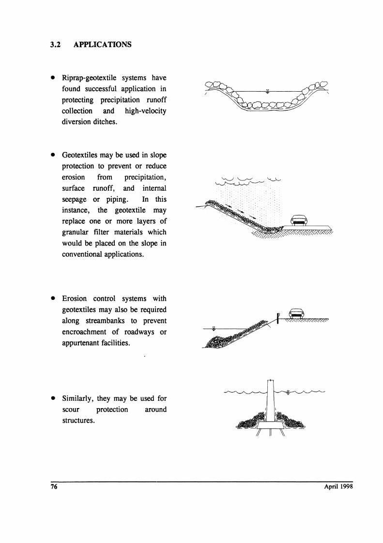
• Riprap-geotextile systems have found successful application in
protecting precipitation runoff
collection and high-velocity diversion ditches.
• Geotextiles may be used in slope protection to prevent or reduce
eroSlOn from precipitation,
surface runoff, and internal
seepage or piping. In this instance, the geotextile may
replace one or more layers of
granular filter materials which
would be placed on the slope in
conventional applications.
• Erosion control systems with geotextiles may also be required
along streambanks to prevent
encroachment of roadways or
appurtenant facilities.
• Similarly, they may be used for scour protection around
structures.
76 April 1998
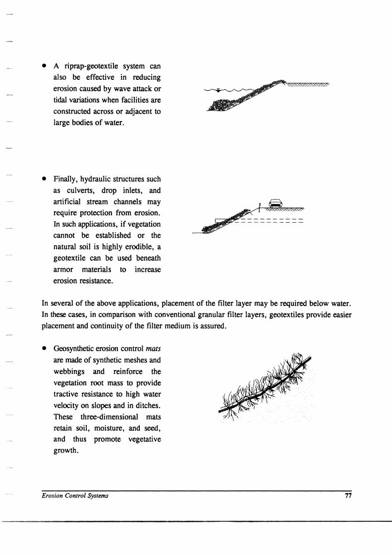
• A riprap-geotextile system can also be effective in reducing
erosion caused by wave attack or
tidal variations when facilities are
constructed across or adjacent to
large bodies of water.
• Finally, hydraulic structures such
as culverts, drop inlets, and
artificial stream channels may
require protection from erosion.
In such applications, if vegetation
cannot be established or the
natural soil is highly erodible, a
geotextile can be used beneath
armor materials to increase
erosion resistance.
~r_~ ~ -----------
In several of the above applications, placement of the filter layer may be required below water.
In these cases, in comparison with conventional granular filter layers, geotextiles provide easier
placement and continuity of the filter medium is assured.
• Geosynthetic erosion control mats are made of synthetic meshes and
webbings and reinforce the
vegetation root mass to provide
tractive resistance to high water
velocity on slopes and in ditches.
These three-dimensional mats
retain soil, moisture, and seed,
and thus promote vegetative
growth.
Erosion Control Systems 77
,,----"'--_.-, ._-------------------------------------
3.3 DESIGN OF GEOTEXTILES BENEA m HARD ARMOR
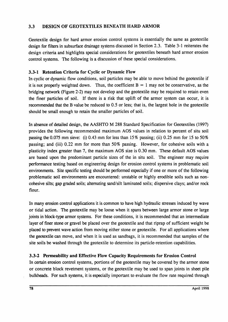
Geotextile design for hard armor erosion control systems is essentially the same as geotextile
design for filters in subsurface drainage systems discussed in Section 2.3. Table 3-1 reiterates the
design criteria and highlights special considerations for geotextiles beneath hard armor erosion
control systems. The following is a discussion of these special considerations.
3.3-1 Retention Criteria for Cyclic or Dynamic Flow In cyclic or dynamic flow conditions, soil particles may be able to move behind the geotextile if
it is not properly weighted down. Thus, the coefficient B = 1 may not be conservative, as the
bridging network (Figure 2-2) may not develop and the geotextile may be required to retain even
the finer particles of soil. If there is a risk that uplift of the armor system can occur, it is
recommended that the B value be reduced to 0.5 or less; that is, the largest hole in the geotextile
should be small enough to retain the smaller particles of soil.
In absence of detailed design, the AASHTO M 288 Standard Specification for Geotextiles (1997)
provides the following recommended maximum AOS values in relation to percent of situ soil
passing the 0.075 mm sieve: (i) 0.43 mm for less than 15 % passing; (ii) 0.25 mm for 15 to 50%
passing; and (iii) 0.22 mm for more than 50% passing. However, for cohesive soils with a
plasticity index greater than 7, the maximum AOS size is 0.30 mm. These default AOS values
are based upon the predominant particle sizes of the in situ soil. The engineer may require
performance testing based on engineering design for erosion control systems in problematic soil
environments. Site specific testing should be performed especially if one or more of the following
problematic soil environments are encountered: unstable or highly erodible soils such as non
cohesive silts; gap graded soils; alternating sand/silt laminated soils; dispersive clays; and/or rock
flour.
In many erosion control applications it is common to have high hydraulic stresses induced by wave
or tidal action. The geotextile may be loose when it spans between large armor stone or large
joints in block-type armor systems. For these conditions, it is recommended that an intermediate
layer of finer stone or gravel be placed over the geotextile and that riprap of sufficient weight be
placed to prevent wave action from moving either stone or geotextile. For all applications where
the geotextile can move, and when it is used as sandbags, it is recommended that samples of the
site soils be washed through the geotextile to determine its particle-retention capabilities.
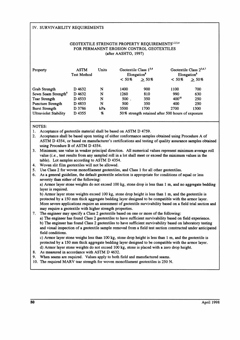
3.3-2 Permeability and Effective Flow Capacity Requirements for Erosion Control In certain erosion control systems, portions of the geotextile may be covered by the armor stone
or concrete block revetment systems, or the geotextile may be used to span joints in sheet pile
bulkheads. For such systems, it is especially important to evaluate the flow rate required through
78 April 1998
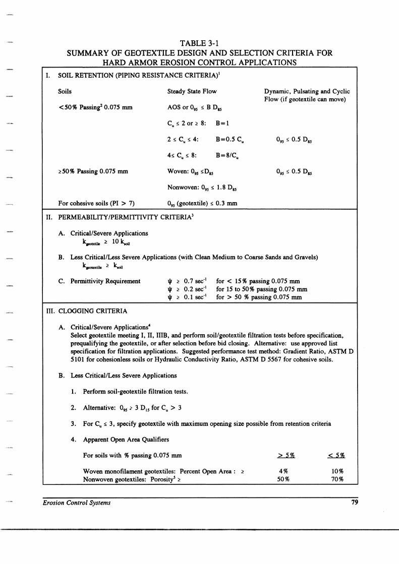
TABLE 3-1 SUMMARY OF GEOTEXTILE DESIGN AND SELECTION CRITERIA FOR
HARD ARMOR EROSION CONTROL APPLICATIONS
I. SOIL RETENTION (PIPING RESISTANCE CRITERIA)I
Soils
<50% Passing2 0.075 mm
~50% Passing 0.075 mm
For cohesive soils (PI > 7)
Steady State Flow
Cu:s 2 or ~ 8: B= 1
Nonwoven: 095 :s 1. 8 D85
095 (geotextile) :s 0.3 mm
Dynamic, Pulsating and Cyclic Flow (if geotextile can move)
II. PERMEABILITY /PERMITTIVITY CRITERIA3
A. Critical/Severe Applications k..,atile ~ 10 kooil
B. Less CriticallLess Severe Applications (with Clean Medium to Coarse Sands and Gravels) kpotexti1e ~ kooil
C. Permittivity Requirement
III. CLOGGING CRITERIA
A. Critical/Severe Applications4
'" ~ 0.7 sec-I '" ~ 0.2 sec-I
'" ~ 0.1 sec-I
for < 15% passing 0.075 mm for 15 to 50% passing 0.075 mm for> 50 % passing 0_075 mm
Select geotextile meeting I, II, IIIB, and perform soillgeotextile filtration tests before specification, prequalifying the geotextile, or after selection before bid closing. Alternative: use approved list specification for filtration applications. Suggested performance test method: Gradient Ratio, ASTM D 5101 for cohesionless soils or Hydraulic Conductivity Ratio, ASTM D 5567 for cohesive soils.
B. Less CriticallLess Severe Applications
1. Perform soil-geotextile filtration tests.
2. Alternative: 095 ? 3 D15 for Cu > 3
3. For Cu :s 3, specify geotextile with maximum opening size possible from retention criteria
4. Apparent Open Area Qualifiers
For soils with % passing 0.075 mm
Woven monofilament geotextiles: Percent Open Area: ~
Nonwoven geotextiles: Porosity5 ~
Erosion Control Systems
4% 50%
10% 70%
79
IV. SURVIVABILITY REQUIREMENTS
GEOTEXTILE STRENGTH PROPERTY REQUIREMENTS1,2.3.4
FOR PERMANENT EROSION CONTROL GEOTEXTILES (after AASHTO, 1997)
Property ASTM Units Geotextile Class 1 S.6 Geotextile Class 2S•6•7
Test Method ElongationS ElongationS < 50% ~50% < 50% ~50%
Grab Strength D 4632 N 1400 900 1100 700 Sewn Seam Strength9 D 4632 N 1260 810 990 630 Tear Strength D4533 N 500 . 350 40010 250 Puncture Strength D 4833 N 500 350 400 250 Burst Strength D 3786 kPa 3500 1700 2700 1300 Ultraviolet Stability D 4355 % 50 % strength retained after 500 hours of exposure
NOTES: 1. Acceptance of geotextile material shall be based on ASTM D 4759. 2. Acceptance shall be based upon testing of either conformance samples obtained using Procedure A of
ASTM D 4354, or based on manufacturer's certifications and testing of quality assurance samples obtained using Procedure B of ASTM D 4354.
3. Minimum; use value in weaker principal direction. All numerical values represent minimum average roll value (i. e., test results from any sampled roll in a lot shall meet or exceed the minimum values in the table). Lot samples according to ASTM D 4354.
4. Woven slit film geotextiles will not be allowed. 5. Use Class 2 for woven monofilament geotextiles, and Class 1 for all other geotextiles. 6. As a general guideline, the default geotextile selection is appropriate for conditions of equal or less
severity than either of the following: a) Armor layer stone weights do not exceed 100 kg, stone drop is less than 1 m, and no aggregate bedding layer is required. b) Armor layer stone weights exceed 100 kg, stone drop height is less than 1 m, and the geotextile is protected by a 150 mm thick aggregate bedding layer designed to be compatible with the armor layer. More severe applications require an assessment of geotextile survivability based on a field trial section and may require a geotextile with higher strength properties.
7. The engineer may specify a Class 2 geotextile based on one or more of the following: a) The engineer has found Class 2 geotextiles to have sufficient survivability based on field experience. b) The engineer has found Class 2 geotextiles to have sufficient survivability based on laboratory testing and visual inspection of a geotextile sample removed from a field test section constructed under anticipated field conditions. c) Armor layer stone weighs less than 100 kg, stone drop height is less than 1 m, and the geotextile is protected by a 150 mm thick aggregate bedding layer designed to be compatible with the armor layer. d) Armor layer stone weights do not exceed 100 kg, stone is placed with a zero drop height.
8. As measured in accordance with ASTM D 4632. 9. When seams are required. Values apply to both field and manufactured seams. 10. The required MARV tear strength for woven monofilament geotextiles is 250 N.
80 April 1998
the open portion of the system and select a geotextile that meets those flow requirements. Again,
since flow is restricted through the geotextile, the requir~ flow capacity is based on the flow
capacity of the area available for flow; or
qrequired = <},eotextiJc(A,/ AJ (Eq. 2 - 9) where: Ag = geotextile area available for flow, and
At = total geotextile area.
The AASHTO M 288 Standard Specification for Geotextiles (1997) presents recommended
minimum permittivity values in relation to percent of situ soil passing the 0.075 mm sieve. The
values are the same as presented in Table 3-1. The default permittivity values are based upon the
predominant particle sizes of the in situ soil. Again, the engineer may require performance testing
based on engineering design for drainage systems in problematic soil environments.
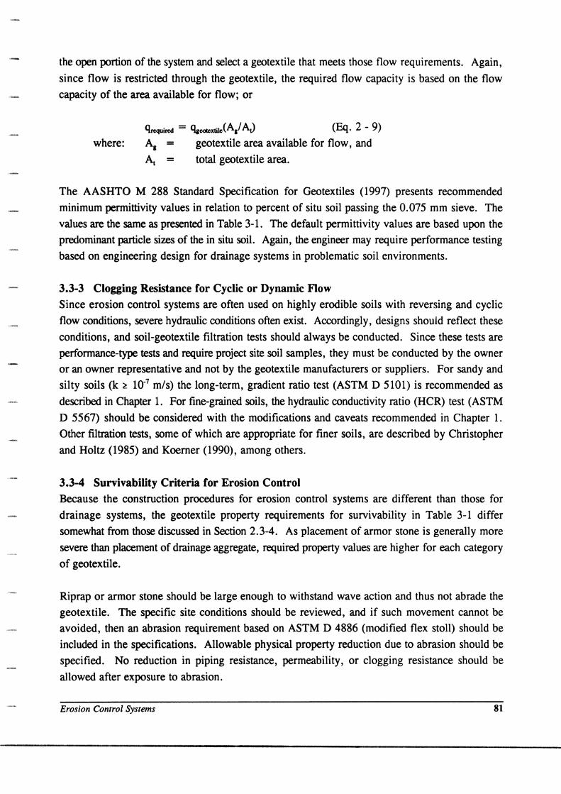
3.3-3 Clogging Resistance for Cyclic or Dynamic Flow Since erosion control systems are often used on highly erodible soils with reversing and cyclic
flow conditions, severe hydraulic conditions often exist. Accordingly, designs should reflect these
conditions, and soil-geotextile filtration tests should always be conducted. Since these tests are
performance-type tests and require project site soil samples, they must be conducted by the owner
or an owner representative and not by the geotextile manufacturers or suppliers. For sandy and
silty soils (k ~ 10-7 mls) the long-term, gradient ratio test (ASTM D 5101) is recommended as
described in Chapter 1. For fine-grained soils, the hydraulic conductivity ratio (HCR) test (ASTM
D 5567) should be considered with the modifications and caveats recommended in Chapter 1.
Other filtration tests, some of which are appropriate for finer soils, are described by Christopher
and Holtz (1985) and Koerner (1990), among others.
3.3-4 Survivability Criteria for Erosion Control Because the construction procedures for erosion control systems are different than those for
drainage systems, the geotextile property requirements for survivability in Table 3-1 differ
somewhat from those discussed in Section 2.3-4. As placement of armor stone is generally more
severe than placement of drainage aggregate, required property values are higher for each category
of geotextile.
Riprap or armor stone should be large enough to withstand wave action and thus not abrade the
geotextile. The specific site conditions should be reviewed, and if such movement cannot be
avoided, then an abrasion requirement based on ASTM D 4886 (modified flex stoll) should be
included in the specifications. Allowable physical property reduction due to abrasion should be
specified. No reduction in piping resistance, permeability, or clogging resistance should be
allowed after exposure to abrasion.
Erosion Control Systems 81

It is important to realize that these minimum survivability values are not based on any systematic
research but on the properties of existing geotextiles which are known to have performed
satisfactorily in hard armor erosion control applications. The values are meant to serve as
guidelines for inexperienced users in selecting geotextiles for routine projects. They are not
intended to replace site-specific evaluation, testing, and design.
3.4 GEOTEXTILE DESIGN GUIDELINES
STEP 1. Application evaluation.
A. Critical/less critical
1. If the erosion control system fails, will there be a risk of loss of life?
2. Does the erosion control system protect a significant structure,. and will failure lead
to significant structural damage?
3. If the geotextile clogs, will failure occur with no warning? Will failure be
catastrophic?
4. If the erosion control system fails, will the repair costs greatly exceed installation
costs?
B. Severe/less severe
1. Are soils to be protected gap-graded, pipable, or dispersive?
2. Are soils present which consist primarily of silts and uniform sands with 85 %
passing the 0.15 mm sieve?
3. Will the erosion control system be subjected to reversing or cyclic flow conditions
such as wave action or tidal variations?
4. Will high hydraulic gradients exist in the soils to be protected? Will rapid
drawdown conditions or seeps or weeps in the soil exist? Will blockage of seeps and
weeps produce high hydraulic pressures?
5. Will high-velocity conditions exist, such as in stream channels?
NOTE: If the answer is yes to any of the above questions, the design should proceed under the critical/severe
requirements; othelWise use the less critical/less severe design approach.
STEP 2. Obtain soil samples from the site.
A. Perform grain size analyses
1. Determine percent passing the 0.075 mm sieve.
82 April 1998
2. Determine the plastic index (PI).
3. Calculate Cu = Dw'DlO'
NOTE: When the protected soil contains particles passing the 0.075 mm sieve, use only the gradation of
soil passing the 4.75 mm sieve in selecting the geotextile (i.e., scalp off the +4.75 mm material).
4. Obtain D8s for each soil and select the worst case soil (i.e., soil with smallest B x D8s) for retention.
B. Perform field or laboratory permeability tests l. Select worse case soil (i.e., soil with highest coefficient of permeability k).
NOTE: The permeability of clean sands « 5 % passing 0.075 mm sieve) with 0.1 mm 0'0 < 3 mm and
Cu < 5 can be estimated by Hazen's formula, k = (0'0)2 (k in cm/s; 0'0 in mm). This formula should not
be used for finer-grained soils.
STEP 3. Evaluate armor material and placement. Design reference: FHWA Hydraulic Engineering Circular No. 15 (FHWA, 1988).
A. Size armor stone or riprap Where minimum size of stone exceeds 100 mm, or greater than a 100 mm gap exists between blocks, an intermediate gravel layer 150 mm thick should be used between the armor stone and geotextile. Gravel should be sized such that it will not wash through the armor stone (i.e., D8s gravel ~ DIS riprap/5).
B. Determine armor stone placement technique (i.e., maximum height of drop).
STEP 4. Calculate anticipated reverse flow through erosion control system. Here we need to estimate the maximum flow from seeps and weeps, maximum flow from wave runout, or maximum flow from rapid drawdown.
A. General case -- use Darcy's law q = kiA
where: q - outflow rate (L3/1)
(Eq. 2 - 15)
k = effective permeability of soil (from Step 2B above) (Ll1)
i-average hydraulic gradient in soil (e.g., tangent of slope angle for wave runoff) (di mensionless)
Erosion Control Systems 83
A = area of soil and drain material normal to the direction of flow (L 2). Can be
evaluated using a unit area.
Use a conventional flow net analysis (Cedergren, 1977) for seepage through dikes and
dams or from a rapid drawdown analysis.
B. Specific erosion control systems -- Hydraulic characteristics depend on expected
precipitation, runoff volumes and flow rates, stream flow volumes and water level
fluctuations, normal and maximum wave heights anticipated, direction of waves and tidal
variations. Detailed information on determination of these parameters is available in the
FHW A (1989) Hydraulic Engineering Circular No. 11.
STEP 5. Determine geotextile requirements.
84
A. Retention Criteria
From Step 2A, obtain Dss and Cu ; then determine largest pore size allowed.
AOS or 095(gwtextile) < B DS5(80il) (Eq. 2 - 1) where: B = 1 for a conservative design.
For a less-conservative design and for ~ 50% passing 0.075 mm sieve:
B = 1 for Cu ~ 2 or ~ 8 (Eq. 2 - 2a)
B = 0.5 Cu for 2 ~ Cu ~ 4 (Eq. 2 - 2b)
B = 8/Cu for 4 < Cu < 8 (Eq. 2 - 2c)
For ~ 50% passing 0.075 mm sieve:
B = 1 for wovens
B = 1.8 for nonwovens
and AOS or 0 95 (geotextile) ~ 0.3 mm
For nondispersive cohesive soils (PI> 7) use:
AOS or 0 95 ~ 0.3 mm
If geotextile and soil retained by it can move:
B = 0.5
B. Permeability/Permittivity Criteria
1. Less Critical/Less Severe
~wtel(tile ~ k.oil
(Eq. 2 - 5)
(Eq. 2 - 7a)
April 1998
2. Critical/Severe
kgeotcxtile ~ 1 0 ~oil
3. Permittivity \j1 Requirement
(Eq. 2 - 8a)
\j1 ~ 0.7 sec'l for < 15% passing 0.075 mm
\j1 ~ 0.2 sec'l for 15 to 50% passing 0.075 mm
\j1 ~ 0.1 sec' I for> 50% passing 0.075 mm
4. Flow Capacity Requirement
Qgeotcxtile ~ (Ai AI) Clrequired or
(kgeotcxtil/ t) h AI ~ qrequired
(from Eq. 2 - 9)
where: qrequired is obtained from Step 4 (Eq. 15) above.
kgeotcxtil/t = \j1 = permittivity
h = average head in field
[3 - 1a]
[3 - 1b]
[3 - 1c]
Ag = area of fabric available for flow (e.g., if 50% of geotextile
covered by flat rocks or riprap, Ag = 0.5 total area)
At = total area of geotextile
C. Clogging Criteria
1. Less critical/less severe
a. Perform soil-geotextile filtration tests.
b. Alternative: From Step 2A obtain DIs; then determine minimum pore size
requirement, for soils with Cu > 3, from
09S ~ 3 DIS (Eq. 2 - 10) c. Other qualifiers
For soils with % passing 0.075 mm > 5 %
Woven monofilament geotextiles: Percent Open Area ~ 4 %
Nonwoven geotextiles: Porosity ~ 50%
2. Critical/severe
10%
70%
Select geotextiles that meet retention, permeability, and survivability criteria; as well as
the criteria in Step 5C.1 above; perform a filtration test.
Suggested filtration test for sandy and silty soils (i.e., k > 10-7 m/s) is the gradient ratio
test as described in Chapter 1. The hydraulic conductivity ratio test (see Chapter 1) is
recommended for fine-grained soils (i.e., k < 10-7 m/s), if appropriately modified.
Erosion Control Systems 85
D. Survivability
Select geotextile properties required for survivability from Table 3-1. Add durability
requirements if applicable. Don't forget to check for abrasion and check drop height.
Evaluate worst case scenario for drop height.
STEP 6. Estimate costs.
Calculate the volume of armor stone, the volume of aggregate and the area of the
geotextile. Apply appropriate unit cost values.
Grading and site preparation (LS)
Geotextile (1m2)
Geotextile placement (1m2)
In-place aggregate bedding layer (1m2) ______ _
Armor stone (lkg)
Armor stone placement (/kg)
Total cost
STEP 7. Prepare specifications.
Include for the geotextile:
A. General requirements
B. Specific geotextile properties
C. Seams and overlaps
D. Placement procedures
E. Repairs
F. Testing and placement observation requirements
See Sections 1.6 and 3.7 for specification details.
STEP 8. Obtain samples of the geotextile before acceptance.
STEP 9. Monitor installation during construction, and control drop height. Observe erosion
control systems during and after significant storm events.
86 April 1998

3.5 GEOTEXTILE DESIGN EXAMPLE
DEFINITION OF DESIGN EXAMPLE
• Project Description: Riprap on slope is required to permit groundwater seepage out of slope face, without erosion of slope. See figure for project cross section.
• Type of Structure: small stone riprap slope protection
• Type of Application: geotextile filter beneath riprap
• Alternatives: i) graded soil filter; or ii) geotextile filter between embankment and riprap
GIYENDATA
• see cross section
• riprap is to allow unimpeded seepage out of slope
• riprap will consist of small stone (50 to 300 mm)
• stone will be placed by dropping from a backhoe
• seeps have been observed in the existing slope
• soil beneath the proposed riprap is a fine silty sand
• gradations of two representative soil samples
GEOTEXTILE
--Project Cross Section
Erosion Control Systems 87
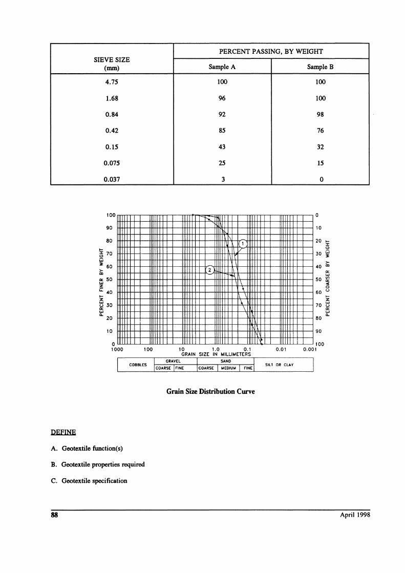
DEFINE
SIEVE SIZE (mm)
4.75
1.68
0.84
0.42
0.15
0.075
0.037
100
90
80
~ 5 70 i:i ~ 60 >-m a:: 50 .... z ;:;: 40 ~ z tl 30 a:: w Q.
20
10
o 1000
A. Geotextile function(s)
100
B. Geotextile properties required
C. Geotextile specification
88
PERCENT PASSING, BY WEIGHT
Sample A Sample B
100 100
96 100
92 98
85 76
43 32
25 15
3 0
0 ...... 10
1\ 1 20 ~
:r
IV I'
(!)
30 i:i ~
\ 2
>-40 CD
a:: "\
\
.... 50 Vl
a:: 4(
\ \
0
60 u ~
'-\
z 70
.... u a:: w Q.
80
90
100 10 1.0 0.1 0.01 0.001
GRAIN SIZE IN MILLIMETERS
SILT OR CLAY
Grain Size Distribution Curve
April 1998
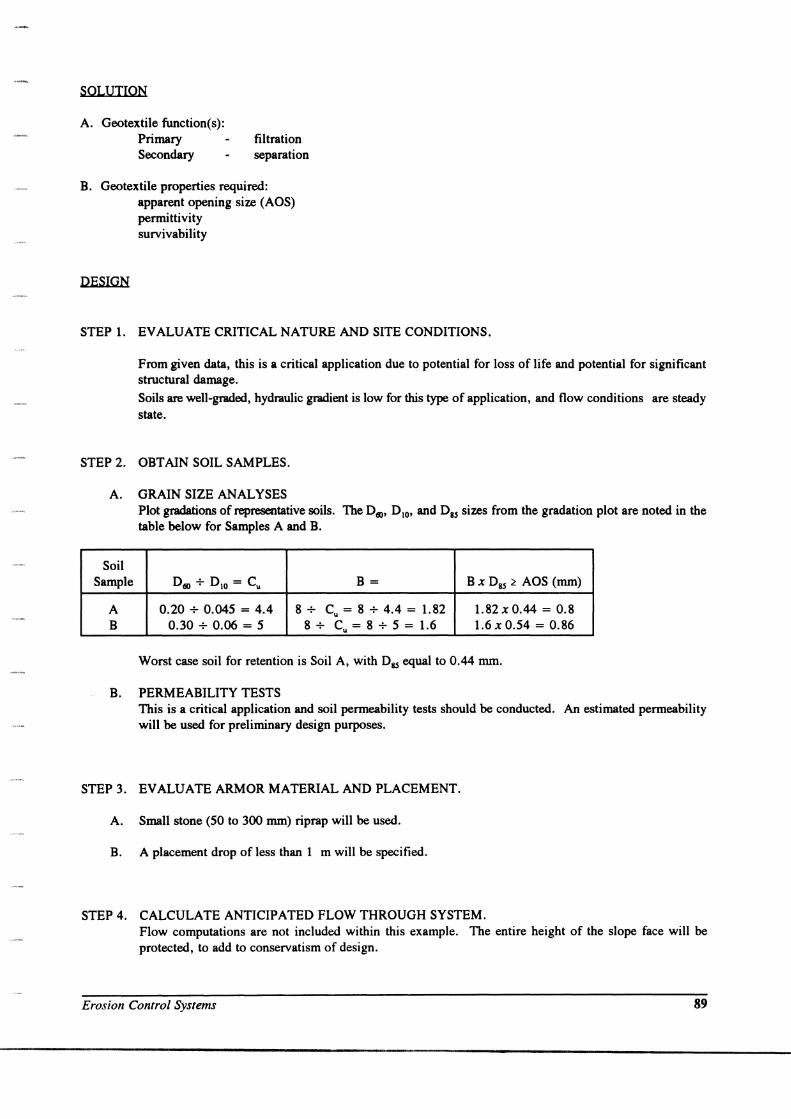
SOLUTION
A. Geotextile function(s): Primary Secondary
filtration separation
B. Geotextile properties required: apparent opening size (AOS) permittivity survivability
DESIGN
STEP 1. EVALUATE CRITICAL NATURE AND SITE CONDITIONS.
From given data, this is a critical application due to potential for loss of life and potential for significant structural damage.
Soils are well-graded, hydraulic gradient is low for this type of application, and flow conditions are steady state.
STEP 2. OBTAIN SOIL SAMPLES.
A. GRAIN SIZE ANALYSES Plot gradations of representative soils. The Dill' DIO, and Dss sizes from the gradation plot are noted in the table below for Samples A and B.
Soil Sample Dill + D IO = Cu B= B X DBS ~ AOS (mm)
A 0.20 + 0.045 = 4.4 8+ Cu = 8 + 4.4 = 1. 82 1.82 x 0.44 = 0.8 B 0.30 + 0.06 = 5 8+ Cu = 8 + 5 = 1.6 1.6 x 0.54 = 0.86
Worst case soil for retention is Soil A, with DBS equal to 0.44 mm.
B. PERMEABILITY TESTS This is a critical application and soil permeability tests should be conducted. An estimated permeability will be used for preliminary design purposes.
STEP 3. EVALUATE ARMOR MATERIAL AND PLACEMENT.
A. Small stone (50 to 300 mm) riprap will be used.
B. A placement drop of less than 1 m will be specified.
STEP 4. CALCULATE ANTICIPATED FLOW THROUGH SYSTEM. Flow computations are not included within this example. The entire height of the slope face will be protected, to add to conservatism of design.
Erosion Control Systems 89
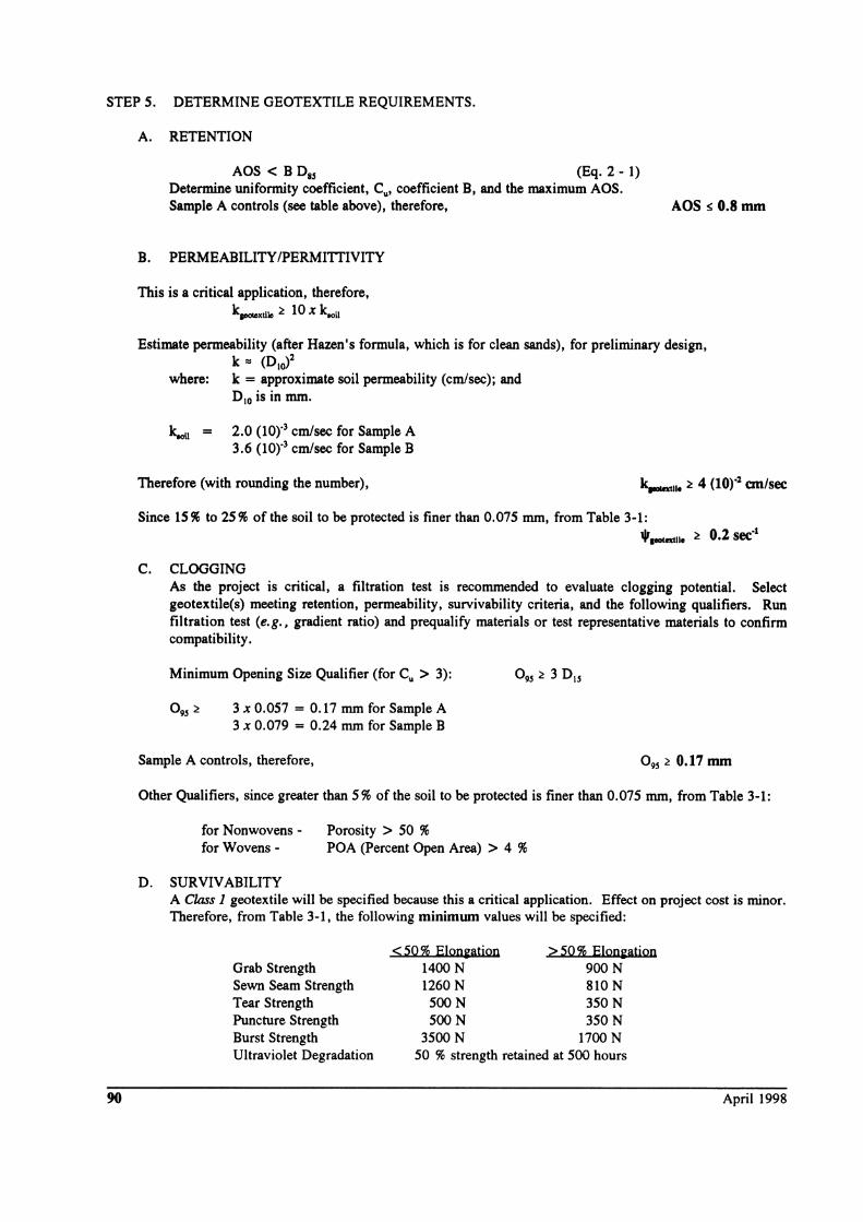
STEP 5. DETERMINE GEOTEXTILE REQUIREMENTS.
90
A. RETENTION
AOS < B 0 85 (Eq. 2 - 1) Determine uniformity coefficient, Cu' coefficient B, and the maximum AOS. Sample A controls (see table above), therefore, AOS s 0.8mm
B. PERMEABILITY /PERMITTIVITY
This is a critical application, therefore, k..-tile :t lOx klOil
Estimate permeability (after Hazen's formula, which is for clean sands), for preliminary design, k'" (01(,)2
where: k = approximate soil permeability (cm/sec); and 0 10 is in mm.
~ = 2.0 (10)"3 cm/sec for Sample A 3.6 (l0)"3 cm/sec for Sample B
Therefore (with rounding the number), k..-II. :t 4 (10)"2 an/sec
Since 15 % to 25 % of the soil to be protected is finer than 0.075 mm, from Table 3-1: .Ir :t 0.2 sec'1 "._11.
C. CLOGGING As the project is critical, a filtration test is recommended to evaluate clogging potential. Select geotextile(s) meeting retention, permeability, survivability criteria, and the following qualifiers. Run filtration test (e.g., gradient ratio) and prequalify materials or test representative materials to confirm compatibility.
Minimum Opening Size Qualifier (for Cu > 3):
0 95 :t 3 x 0.057 = 0.17 mm for Sample A 3 x 0.079 = 0.24 mm for Sample B
Sample A controls, therefore, 0 95 :t 0.17 mm
Other Qualifiers, since greater than 5 % of the soil to be protected is finer than 0.075 mm, from Table 3-1:
for Nonwovens - Porosity > 50 % for Wovens - POA (Percent Open Area) > 4 %
D. SURVIVABILITY A Class 1 geotextile will be specified because this a critical application. Effect on project cost is minor. Therefore, from Table 3-1, the following minimum values will be specified:
Grab Strength Sewn Seam Strength Tear Strength Puncture Strength Burst Strength Ultraviolet Degradation
< 50 % Elon~atjon 1400 N 1260 N 500N 500N
3500 N
> 50 % Elon~atjon 900N 810 N 350N 350N
1700 N 50 % strength retained at 500 hours
April 1998
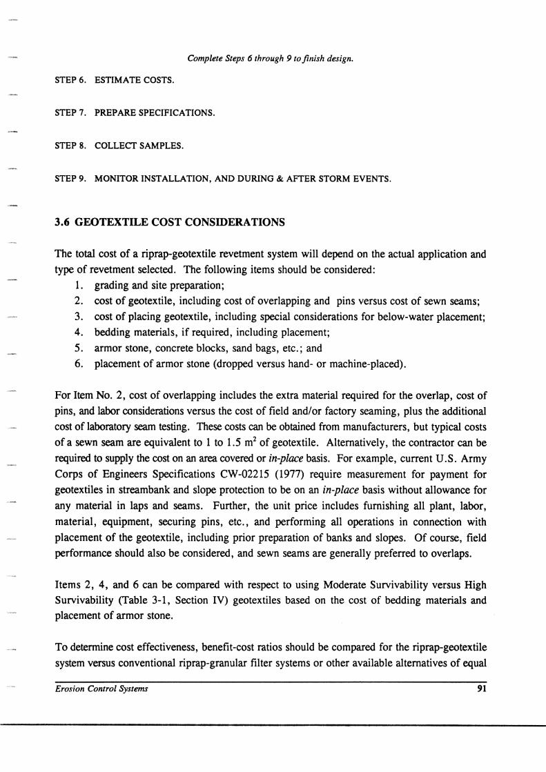
Complete Steps 6 through 9 to finish design.
STEP 6. ESTIMATE COSTS.
STEP 7. PREPARE SPECIFICATIONS.
STEP 8. COLLECT SAMPLES.
STEP 9. MONITOR INSTALLATION, AND DURING & AFTER STORM EVENTS.
3.6 GEOTEXTILE COST CONSIDERATIONS
The total cost of a riprap-geotextile revetment system will depend on the actual application and
type of revetment selected. The following items should be considered:
1. grading and site preparation;
2. cost of geotextile, including cost of overlapping and pins versus cost of sewn seams;
3. cost of placing geotextile, including special considerations for below-water placement;
4. bedding materials, if required, including placement;
5. armor stone, concrete blocks, sand bags, etc.; and
6. placement of armor stone (dropped versus hand- or machine-placed).
For Item No.2, cost of overlapping includes the extra material required for the overlap, cost of
pins, and labor considerations versus the cost of field and/or factory seaming, plus the additional
cost of laboratory seam testing. These costs can be obtained from manufacturers, but typical costs
of a sewn seam are equivalent to 1 to 1.5 m2 of geotextile. Alternatively, the contractor can be
required to supply the cost on an area covered or in-place basis. For example, current U.S. Army
Corps of Engineers Specifications CW-02215 (1977) require measurement for payment for
geotextiles in streambank and slope protection to be on an in-place basis without allowance for
any material in laps and seams. Further, the unit price includes furnishing all plant, labor,
material, equipment, securing pins, etc., and performing all operations in connection with
placement of the geotextile, including prior preparation of banks and slopes. Of course, field
performance should also be considered, and sewn seams are generally preferred to overlaps.
Items 2, 4, and 6 can be compared with respect to using Moderate Survivability versus High
Survivability (Table 3-1, Section IV) geotextiles based on the cost of bedding materials and
placement of armor stone.
To determine cost effectiveness, benefit-cost ratios should be compared for the riprap-geotextile
system versus conventional riprap-granular filter systems or other available alternatives of equal
Erosion Control Systems 91
technical feasibility and operational practicality. Average cost of geotextile protection systems
placed above the water level, including slope preparation, geotextile cost of seaming or securing
pins, and placement is approximately $3.00-6.00 per square meter, excluding the armor stone.
Cost of placement below water level can vary considerably depending on the site conditions and
the contractor's experience. For below-water placement, it is recommended that prebid meetings
be held with potential contractors to explore ideas for placement and discuss anticipated costs.
3.7 GEOTEXTILE SPECIFICATIONS
In addition to the general recommendations concerning specifications in Chapter I, erosion control
specifications must include construction details (see Section 3.8), as the appropriate geotextile will
depend on the placement technique. In addition, the specifications should require the contractor
to demonstrate through trial sections that the proposed riprap placement technique will not damage
the geotextile.
Many erosion control projects may be better-served by performance-type filtration tests that
provide an indication of long-term performance. Thus, in many cases, approved list-type
specifications, as discussed in Section 1.6, may be appropriate. To develop the list of approved
geotextiles, filtration studies (as suggested in Section 3.4, Step 4) should be performed using
problem soils and conditions that exist in the localities where geotextiles will be used. An
approved list for each condition should be established. In addition, geotextiles should be classified
as High or Moderate Survivability geotextiles, in accordance with the index properties listed in
Table 3-1 and construction conditions.
The following example specification is a combination of the AASHTO M288 (1997) geotextile
material specification and its accompanying construction/installation guidelines. It includes the
requirements discussed in Section 1.6 for a good specification. As with the specification presented
in Chapter 2, site-specific hydraulic and physical properties must be appropriately selected and
included.
1. SCOPE
EROSION CONTROL GEOTEXTILE SPECIFICATION (after AASHTO M288, 1997)
1.1 Description. This specification is applicable to the use of a geotextile between energy absorbing armor systems and the in situ soil to prevent soil loss resulting in excessive scour and to prevent hydraulic uplift pressure causing instability of the permanent erosion control system. This specification does not apply to other types of geosynthetic soil erosion control materials such as turf reinforcement mats.
92 April 1998
2. REFERENCED DOCUMENTS
2.1 AASHTO Standards
T88 Particle Size Analysis of Soils T90 Determining the Plastic Limit and Plasticity Index of Soils T99 The Moisture-Density Relationships of Soils Using a 2.5 kg Rammer and a 305 mm Drop
2.2 ASTM Standards
Standard Terminology Relating to Textiles Test Methods for Identification of Fibers in Textiles
D 123 D276 D 3786 Test Method for Hydraulic Burst Strength of Knitted Goods and Nonwoven Fabrics, Diaphragm
Bursting Strength Tester Method Practice for Sampling of Geosynthetics for Testing D4354
D4355 Test Method for Deterioration of Geotextiles from Exposure to Ultraviolet Light and Water (Xenon Arc Type Apparatus) Terminology for Geosynthetics Test Methods for Water Permeability of Geotextiles by Permittivity Test Method for Grab Breaking Load and Elongation of Geotextiles Test Method for Determining Apparent Opening Size of a Geotextile Practice for Determining the Specification Conformance of Geosynthetics
D4439 D 4491 D 4632 D4751 D4759 D 4833 D 4873 D 5141
Test Method for Index Puncture Resistance of Geotextiles, Geomembranes and Related Products Guide for Identification, Storage, and Handling of Geotextiles Test Method to Determine Filtering Efficiency and Flow Rate for Silt Fence Applications Using Site Specific Soil
3. PHYSICAL AND CHEMICAL REQUIREMENTS
3.1 Fibers used in the manufacture of geotextiles and the threads used in joining geotextiles by sewing, shall consist of long chain synthetic polymers, composed of at least 95 % by weight polyolefins or polyesters. They shall be formed into a stable network such that the filaments or yams retain their dimensional stability relative to each other, including selvages.
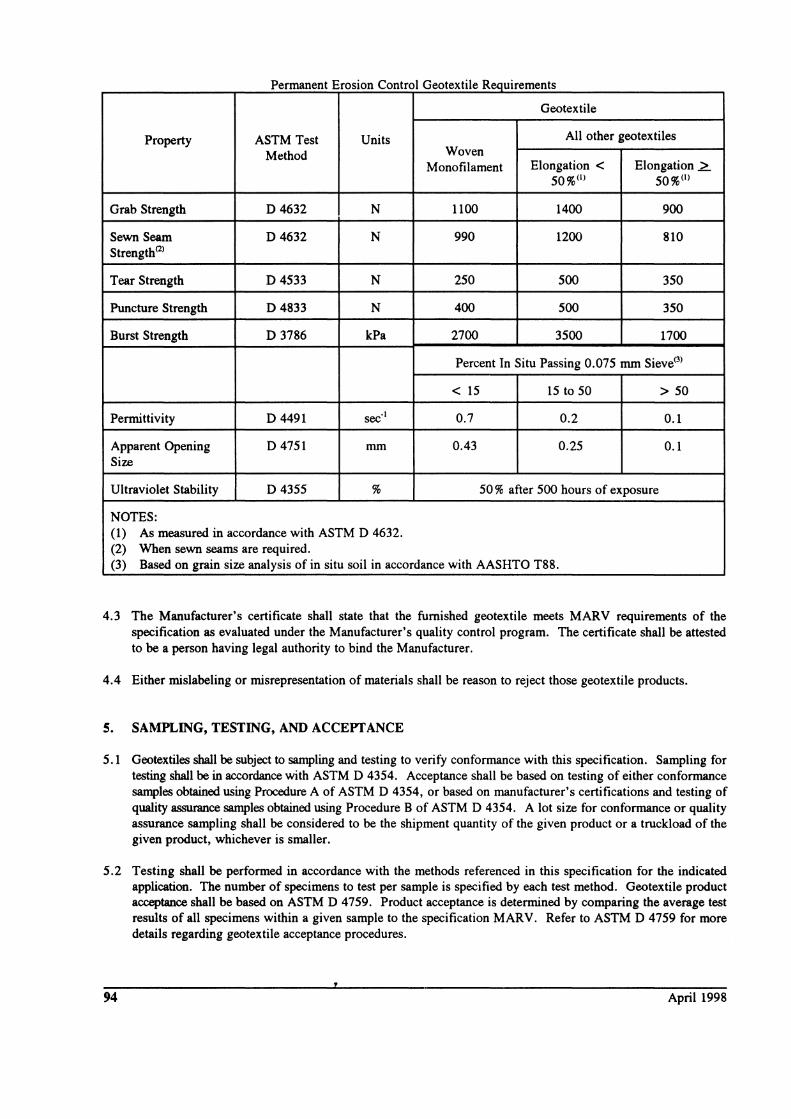
3.2 Geotextile Requirements. The geotextile shall meet the requirements of following Table. Woven slit film geotextiles (i.e., geotextiles made from yams of a flat, tape-like character) will not be allowed. All numeric values in the following table, except AOS, represent minimum average roll values (MARV) in the weakest principal direction (i. e., average test results of any roll in a lot sampled for conformance or quality assurance testing shall meet or exceed the minimum values). Values for AOS represent maximum average roll values.
NOTE: The property values in the following table represent default values which provide for sufficient geotextile survivability under most conditions. Minimum property requirements may be reduced when sufficient survivability information is available [see Note 5 of Table 2-2 and Appendix D]. The Engineer may also specify properties different from those listed in the following Table based on engineering design and experience.
4. CERTIFICATION
4.1 The Contractor shall provide to the Engineer a certificate stating the name of the manufacturer, product name, style number, chemical composition of the filaments or yams and other pertinent information to fully describe the geotextile.
4.2 The Manufacturer is responsible for establishing and maintaining a quality control program to assure compliance with the requirements of the specification. Documentation describing the quality control program shall be made available upon request.
Erosion Control Systems 93
P ermanent E roslOn c ontro IG eotexh e ,eqUirements '1 R
Geotextile
Property ASTM Test Units All other geotextiles
Method Woven Monofilament Elongation < Elongation L
50%0) 50%0)
Grab Strength D4632 N 1100 1400 900
Sewn Seam D 4632 N 990 1200 810 Strength(2)
Tear Strength D4533 N 250 500 350
Puncture Strength D4833 N 400 500 350
Burst Strength D 3786 kPa 2700 3500 1700
Percent In Situ Passing 0.075 mm Sieve(3)
< 15 15 to 50 > 50
Permittivity D4491 sec'l 0.7 0.2 0.1
Apparent Opening D4751 mm 0.43 0.25 0.1 Size
Ultraviolet Stability D4355 % 50 % after 500 hours of exposure
NOTES: (1) As measured in accordance with ASTM D 4632. (2) When sewn seams are required. (3) Based on grain size analysis of in situ soil in accordance with AASHTO T88.
4.3 The Manufacturer's certificate shall state that the furnished geotextile meets MARV requirements of the specification as evaluated under the Manufacturer's quality control program. The certificate shall be attested to be a person having legal authority to bind the Manufacturer.
4.4 Either mislabeling or misrepresentation of materials shall be reason to reject those geotextile products.
5. SAMPLING, TESTING, AND ACCEPTANCE
5.1 Geotextiles shall be subject to sampling and testing to verify conformance with this specification. Sampling for testing shall be in accordance with ASTM D 4354. Acceptance shall be based on testing of either conformance samples obtained using Procedure A of ASTM D 4354, or based on manufacturer's certifications and testing of quality assurance samples obtained using Procedure B of ASTM D 4354. A lot size for conformance or quality assurance sampling shall be considered to be the shipment quantity of the given product or a truckload of the given product, whichever is smaller.
5.2 Testing shall be performed in accordance with the methods referenced in this specification for the indicated application. The number of specimens to test per sample is specified by each test method. Geotextile product acceptance shall be based on ASTM D 4759. Product acceptance is determined by comparing the average test results of all specimens within a given sample to the specification MARV. Refer to ASTM D 4759 for more details regarding geotextile acceptance procedures.
94 April 1998
6. SHIPMENT AND STORAGE
6.1 Geotextile labeling, shipment, and storage shall follow ASTM D 4873. Product labels shall clearly show the manufacturer or supplier name, style number, and roll number. Each shipping document shall include a notation certifying that the material is in accordance with the manufacturer's certificate.
6.2 Each geotextile roll shall be wrapped with a material that will protect the geotextile from damage due to shipment, water, sunlight, and contaminants. The protective wrapping shall be maintained during periods of shipment and storage.
6.3 During storage, geotextile rolls shall be elevated off the ground and adequately covered to protect them from the following: site construction damage, precipitation, extended ultraviolet radiation including sunlight, chemicals that are strong acids or strong bases, flames including welding sparks, temperatures in excess of 71°C (160°F), and any other environmental condition that may damage the physical property values of the geotextile.
7. CONSTRUCTION
7.1 General. Atmospheric exposure of geotextiles to the elements following lay down shall be a maximum of 14 days to minimize damage potential.
7.2 Seaming.
a. If a sewn seam is to be used for the seaming of the geotextile, the thread used shall consist of high strength polypropylene, or polyester. Nylon thread shall not be used. For erosion control applications, the thread shall also be resistant to ultraviolet radiation. The thread shall be of contrasting color to that of the geotextile itself.
b. For seams which are sewn in the field, the Contractor shall provide at least a 2 m length of sewn seam for sampling by the Engineer before the geotextile is installed. For seams which are sewn in the factory, the Engineer shall obtain samples of the factory seams at random from any roll of geotextile which is to be used on the project.
b.l For seams that are field sewn, the seams sewn for sampling shall be sewn using the same equipment and procedures as will be used for the production of seams. If seams are to be sewn in both the machine and cross machine directions, samples of seams from both directions shall be provided.
b.2 The seam assembly description shall be submitted by the Contractor along with the sample of the seam. The description shall include the seam type, stitch type, sewing thread, and stitch density.
7.3 Geotextile Placement.
a. The geotextile shall be placed in intimate contact with the soils without wrinkles or folds and anchored on a smooth graded surface approved by the Engineer. The geotextile shall be placed in such a manner that placement of the overlying materials will not excessively stretch so as to tear the geotextile. Anchoring of the terminal ends of the geotextile shall be accomplished through the use of key trenches or aprons at the crest and toe of slope. See Figures 3-2 and 3-3 [this manual].
NOTE 1: In certain applications to expedite construction, 450 mm anchoring pins placed on 600 to 1800 mm centers, depending on the slope of the covered area, have been used successfully.
a.2 Care shall be taken during installation so as to avoid damage occurring to the geotextile as a result of the installation process. Should the geotextile be damaged during installation, a geotextile patch shall be placed over the damaged area extending 1 m beyond the perimeter of the damage.
Erosion Control Systems 95
b. Annor. The armor system placement shall begin at the toe and proceed up the slope. Placement shall take place so as to avoid stretching resulting in tearing of the geotextile. Riprap and heavy stone filling shall not be dropped from a height of more than 300 mm. Stone weighing more than 450 N shall not be allowed to roll down the slope.
b.1 Slope protection and smaller sizes of stone filling shall not be dropped from a height exceeding 1 m, or a demonstration provided showing that the placement procedures will not damage the geotextile. In under water applications, the geotextile and backfill material shall be placed the same day. All void spaces in the armor stone shall be hckfilled with small stone to ensure full coverage.
b.2 Following placement of the armor stone, grading of the slope shall not be permitted if the grading results in movement of the stone directly above the geotextile.
c. Damage. Field monitoring shall be performed to verify that the armor system placement does not damage the geotextile.
c.1 Any geotextile damaged during backfill placement shall be replaced as directed by the Engineer, at the Contractor's expense.
8. METHOD OF MEASUREMENT
8.1 The geotextile shall be measured by the number of square meters computed from the payment lines shown on the plans or from payment lines established in writing by the Engineer. This excludes seam overlaps, but shall include geotextiles used in crest and toe of slope treatments.
8.2 Slope preparation, excavation and backfill, bedding, and cover material are separate pay items.
9. BASISOFPAYMENT
9.1 The accepted quantities of geotextile shall be paid for per square meter in place.
9.2 Payment will be made under:
Pay Item Pay Unit
Erosion Control Geotextile Square Meter
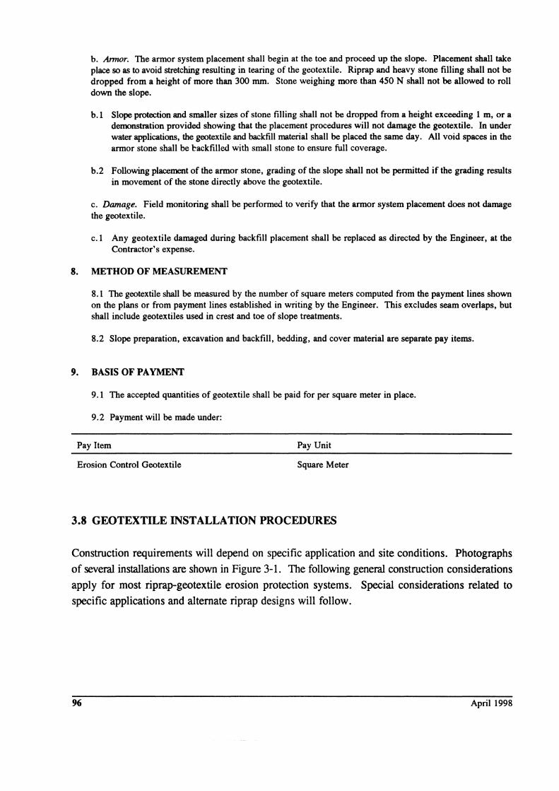
3.8 GEOTEXTILE INSTALLATION PROCEDURES
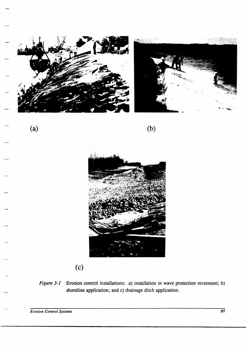
Construction requirements will depend on specific application and site conditions. Photographs
of several installations are shown in Figure 3-1. The following general construction considerations
apply for most riprap-geotextile erosion protection systems. Special considerations related to
specific applications and alternate riprap designs will follow.
96 April 1998
(a) (b)
(c)
Figure 3-1 Erosion control installations: a) installation in wave protection revetment; b)
shoreline application; and c) drainage ditch application.
Erosion Control Systems 97
3.8-1 General Construction Considerations
98
1. Grade area and remove debris to provide smooth, fairly even surface.
a. Depressions or holes in the slope should be filled to avoid geotextile bridging and
possible tearing when cover materials are placed.
b. Large stones, limbs, and other debris should be removed prior to placement to
prevent fabric damage from tearing or puncturing during stone placement.
2. Place geotextile loosely, laid with machine direction in the direction of anticipated water
flow or movement.
3. Seam or overlap the geotextile as required.
a. For overlaps, adjacent rolls of geotextile should be overlapped a minimum of 0.3 m.
Overlaps should be in the direction of water flow and stapled or pinned to hold the
overlap in place during placement of stone. Steel pins are normally 5 mm diameter,
0.5 m long, pointed at one end, and fitted with 40 mm diameter washers at the other
end. Pins should be spaced along all overlap alignments at a distance of
approximately 1 m center to center.
b. The geotextile should be pinned loosely so it can easily conform to the ground
surface and give when stone is placed.
c. If seamed, seam strength should equal or exceed the minimum seam requirements
indicated in the specification section of Chapter 1.
4. The maximum allowable slope on which a riprap-geotextile system can be placed is equal
to the lowest soil-geotextile friction angle for the natural ground or stone-geotextile
friction angle for cover (armor) materials. Additional reductions in slope may be
necessary due to hydraulic considerations and possible long-term stability conditions.
For slopes greater than 2.5 to 1, special construction procedures will be required,
including toe berms to provide a buttress against slippage, loose placement of geotextile
sufficient to allow for downslope movement, elimination of pins at overlaps, increase in
overlap requirements, and possible benching of the slope. Care should be taken not to
put irregular wrinkles in the geotextile because erosion channels can form beneath the
geotextile.
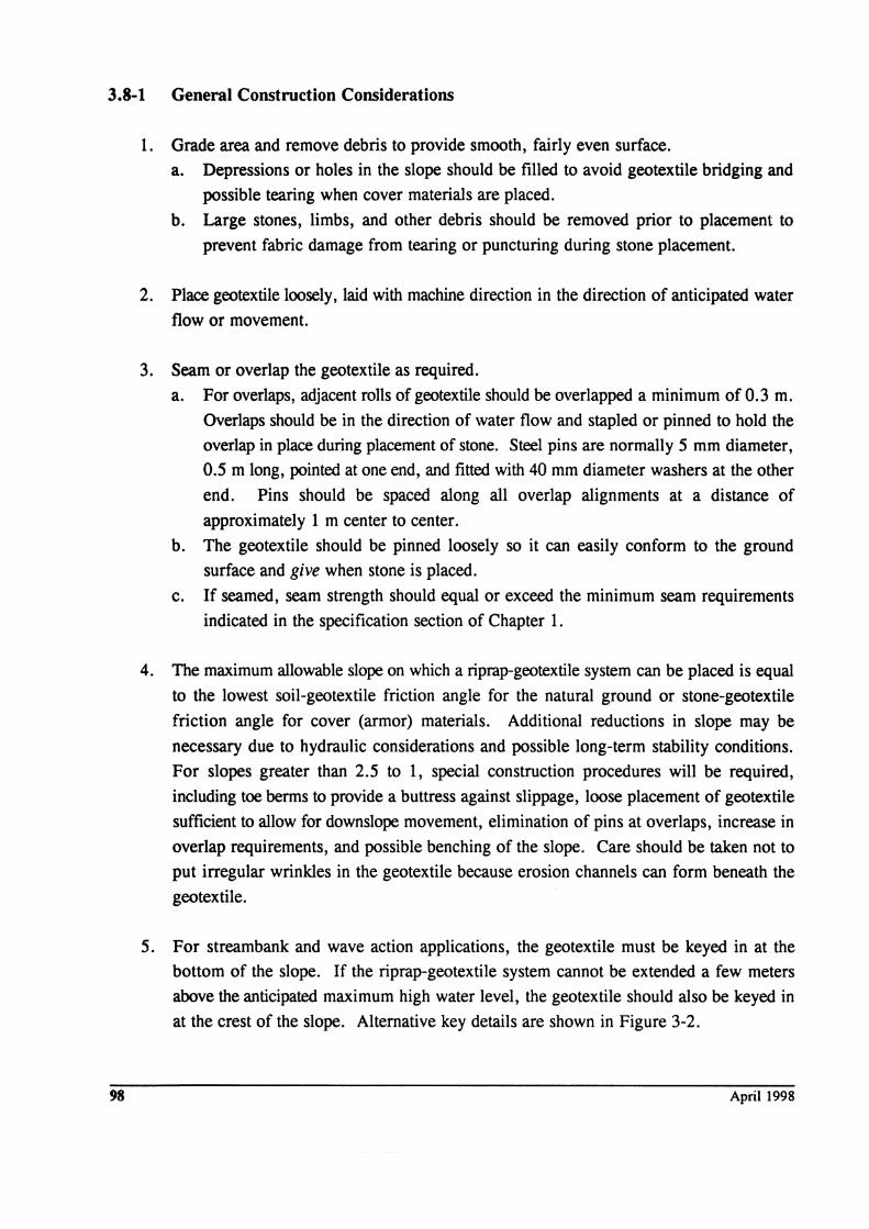
5. For streambank and wave action applications, the geotextile must be keyed in at the
bottom of the slope. If the riprap-geotextile system cannot be extended a few meters
above the anticipated maximum high water level, the geotextile should also be keyed in
at the crest of the slope. Alternative key details are shown in Figure 3-2.
April 1998
SAllE STONE USED ~+'1VjN REVETWENT
~!!
,~'fo'" ./ o E.
" ~ o 0
~ rASRIC
(0) CROSS-SECTION OF REVETMENT AND KEY TRENCHES
WAVE ATTACK ..
SZIlEAN LOW WATER --=- ..,,+. '\ iLACE COVER ,~'" ;;TONE UPSLOPE ,{ ~
~EllaANKWENT rlLLJ
SAWE STONE USEO IN REVETWENT
STABLE SLOPE ANGLES rOR NATURAL/EWBANKWENT SOILS
(b) CROSS-SECTION USING KEY TRENCH WHEN SOIL CONDITIONS DO NOT PERMIT VERTICAL WALL CONSTRUCTION
¥ IIEAN LOW WATER
APRON
.... ....
(c) DUTCH METHOD OF TOE DESIGN
Figure 3-2 Construction of hard armor erosion control systems (a., b. after Keown and
Dardeau, 1980; c. after Dunham and Barrett, 1974)
Erosion Control Systems
6. Place revetment (cushion layer and/or riprap) over the geotextile width, while avoiding
puncturing or tearing it.
a. Revetment should be placed on the geotextile within 14 days.
b. Placement of armor cover will depend on the type of riprap, whether quarry stone,
sandbags (which may be constructed of geotextiles), interlocked or articulating
concrete blocks, soil-cement filled bags, or other suitable slope protection is used.
c. For sloped surfaces, placement should always start from the base of the slope,
moving up slope and, preferably, from the center outward.
d. In no case should stone weighing more than 400 N be allowed to roll downslope on
the geotextile.
e. Field trials should be performed to determine if placement techniques will damage
the geotextile and to determine the maximum height of safe drop. As a general
guideline, for Moderate Survivability geotextiles (Table 3-1) with no cushion layer,
height of drop for stones less than 100 kg should be less than 300 mm. For High
Survivability geotextiles (Table 3-1) or Moderate Survivability geotextiles with a
cushion layer, height of drop for stones less than 100 kg should be less than 0.9 m.
Stones greater than 100 kg should be placed with no free fall unless field trials
demonstrate they can be dropped without damaging the geotextile.
f. Grading of slopes should be performed during placement of riprap. Grading should
not be allowed after placement if it results in stone movement directly on the
geotextile.
As previously indicated, construction requirements will depend on specific application and site
conditions. In some cases, geotextile selection is affected by construction procedures. For
example, if the system will be placed below water, a geotextile that facilitates such placement
must be chosen. The geotextile may also affect the construction procedures. For example, the
geotextile must be completely covered with riprap for protection from long-term exposure to
ultraviolet radiation. Sufficient anchorage must also be provided by the riprap for weighting the
geotextile in below-water applications. Other requirements related to specific applications are
depicted in Figure 3-3 and are reviewed in the following subsections (from Christopher and Holtz,
1985).
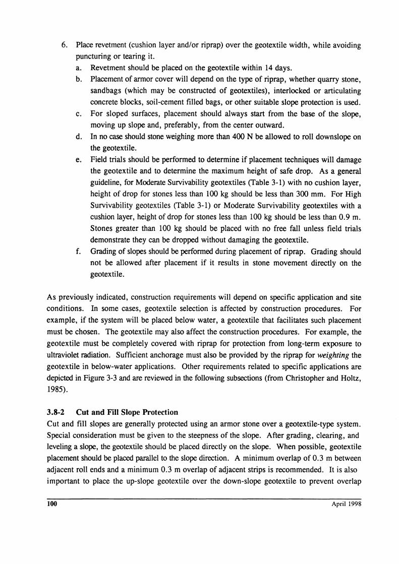
3.8-2 Cut and Fill Slope Protection
Cut and fill slopes are generally protected using an armor stone over a geotextile-type system.
Special consideration must be given to the steepness of the slope. After grading, clearing, and
leveling a slope, the geotextile should be placed directly on the slope. When possible, geotextile
placement should be placed parallel to the slope direction. A minimum overlap of 0.3 m between
adjacent roll ends and a minimum 0.3 m overlap of adjacent strips is recommended. It is also
important to place the up-slope geotextile over the down-slope geotextile to prevent overlap
100 April 1998
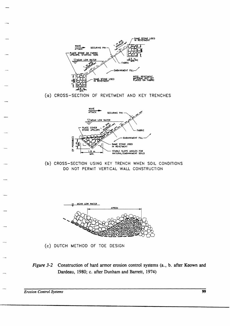
TOP OF' BANK
DIRECTION OF' CURRENT ------~~-------------------,,---~-----------
MACHINE DIRECTION
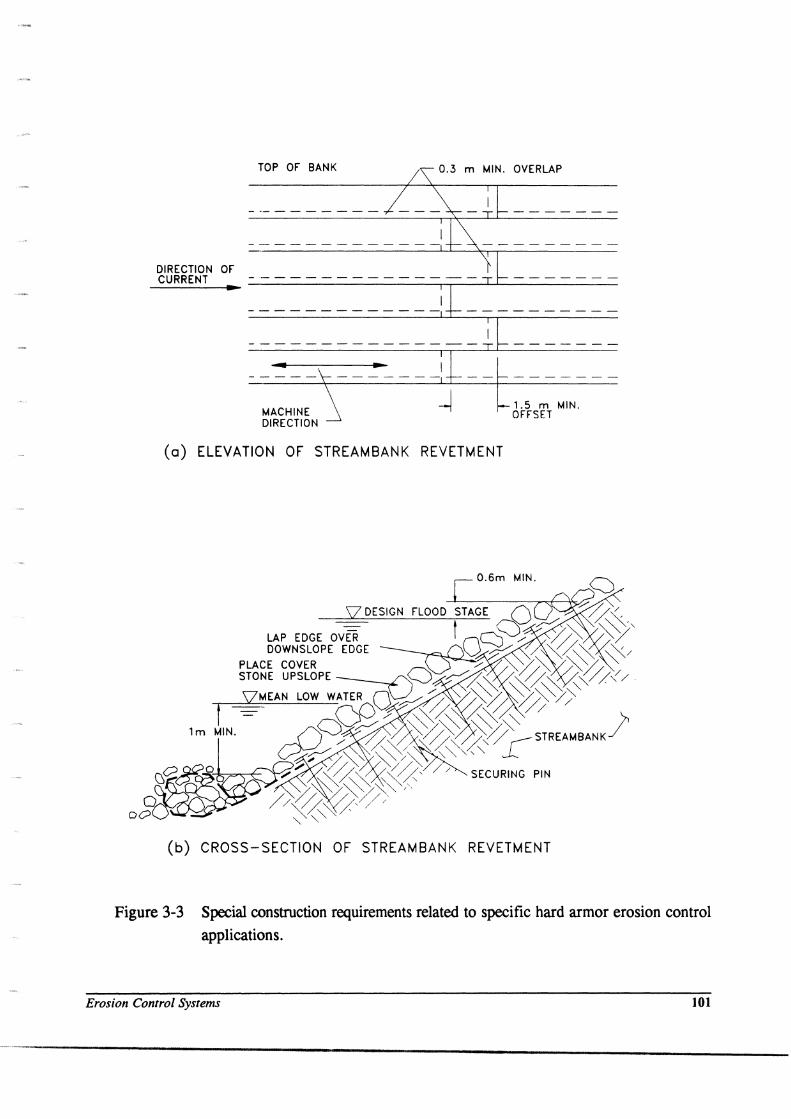
(a) ELEVATION OF STREAMBANK REVETMENT
1.5 m MIN. OFFSET
O.6m MIN.
(b) CROSS-SECTION OF STREAMBANK REVETMENT
Figure 3-3 Special construction requirements related to specific hard armor erosion control
applications.
Erosion Control Systems 101
/
"-- NATURAL ./ SOIL~
\
- SECURING PIN
IF TWO GEOTEXTILE STRIPS ARE REQUIRED, SEW SEAM INSTEAD OF OVERLAPPING
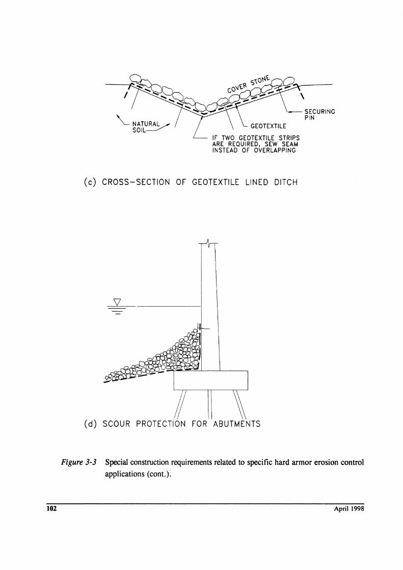
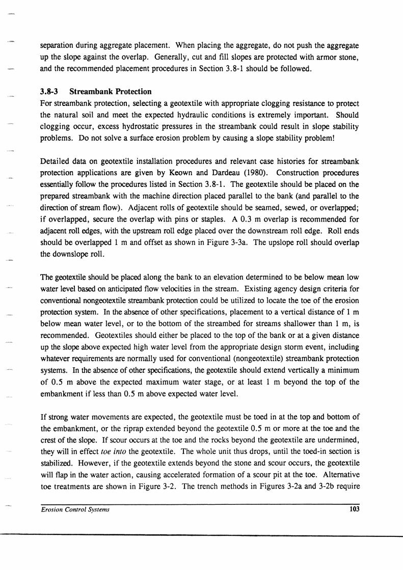
(c) CROSS-SECTION OF GEOTEXTILE LINED DITCH
(d) SCOUR PROTECTION FOR ABUTMENTS
Figure 3-3 Special construction requirements related to specific hard armor erosion control
applications (cont.).
102 April 1998
separation during aggregate placement. When placing the aggregate, do not push the aggregate
up the slope against the overlap. Generally, cut and fill slopes are protected with armor stone,
and the recommended placement procedures in Section 3.8-1 should be followed.
3.8-3 Streambank Protection For streambank protection, selecting a geotextile with appropriate clogging resistance to protect
the natural soil and meet the expected hydraulic conditions is extremely important. Should
clogging occur, excess hydrostatic pressures in the streambank could result in slope stability
problems. Do not solve a surface erosion problem by causing a slope stability problem!
Detailed data on geotextile installation procedures and relevant case histories for stream bank
protection applications are given by Keown and Dardeau (1980). Construction procedures
essentially follow the procedures listed in Section 3.8-1. The geotextile should be placed on the
prepared streambank with the machine direction placed parallel to the bank (and parallel to the
direction of stream flow). Adjacent rolls of geotextile should be seamed, sewed, or overlapped;
if overlapped, secure the overlap with pins or staples. A 0.3 m overlap is recommended for
adjacent roll edges, with the upstream roll edge placed over the downstream roll edge. Roll ends
should be overlapped 1 m and offset as shown in Figure 3-3a. The upslope roll should overlap
the downslope roll.
The geotextile should be placed along the bank to an elevation determined to be below mean low
water level based on anticipated flow velocities in the stream. Existing agency design criteria for
conventional nongeotextile streambank protection could be utilized to locate the toe of the erosion
protection system. In the absence of other specifications, placement to a vertical distance of 1 m
below mean water level, or to the bottom of the streambed for streams shallower than 1 m, is
recommended. Geotextiles should either be placed to the top of the bank or at a given distance
up the slope above expected high water level from the appropriate design storm event, including
whatever requirements are normally used for conventional (nongeotextile) streambank protection
systems. In the absence of other specifications, the geotextile should extend vertically a minimum
of 0.5 m above the expected maximum water stage, or at least 1 m beyond the top of the
embankment if less than 0.5 m above expected water level.
If strong water movements are expected, the geotextile must be toed in at the top and bottom of
the embankment, or the riprap extended beyond the geotextile 0.5 m or more at the toe and the
crest of the slope. If scour occurs at the toe and the rocks beyond the geotextile are undermined,
they will in effect toe into the geotextile. The whole unit thus drops, until the toed-in section is
stabilized. However, if the geotextile extends beyond the stone and scour occurs, the geotextile
will flap in the water action, causing accelerated formation of a scour pit at the toe. Alternative
toe treatments are shown in Figure 3-2. The trench methods in Figures 3-2a and 3-2b require
Erosion Control Systems 103
excavating a trench at the toe of the slope. This may be a good alternative for new construction;
however, it should be evaluated with respect to slope stability when a trench will be excavated at
the toe of a potentially saturated slope below the water level. Keying in at the top can consist of
burying the top bank edge of the geotextile in a shallow trench. This will provide resistance to
undermining from infiltration of over-the-bank precipitation runoff, and also provide stability
should a storm greater than anticipated occur. However, unless excessive quantities of runoff are
expected and stream flows are relatively small, this step is usually omitted.
The armoring material (e.g., riprap, sandbags, blocks) must be placed to avoid tearing or
puncturing the geotextile, as indicated in Section 3.8-1.
3.8-4 Precipitation Runoff Collection and Diversion Ditches Runoff drainage from cut slopes along the sides of roads and in the median of divided highways
is normally controlled with one or more gravity flow ditches. Runoff from the pavement surface
and shoulder slopes are collected and conveyed to drop inlets, stream channels, or other highway
drainage structures. If a rock protection-geotextile system is used to control localized ditch
erosion problems, select and specify the geotextile using the properties indicated in Table 3-1.
Geotextile requirements for ditch linings are less critical than for other types of erosion protection,
and minimum requirements for noncritical, nonsevere applications can generally be followed. If
care is taken during construction, the protected strength requirements appear reasonable. The
geotextile should be sized with AOS to prevent scour and piping erosion of the underlying natural
soil and to be strong enough to survive stone placement.
The ditch alignment should be graded fairly smooth, with depressions and gullies filled and large
stones and other debris moved from the ditch alignment. The geotextile should be placed with the
machine direction parallel to the ditch alignment. Most geotextiles are available in widths of 2
m or more, and, thus, a single roll width of geotextile may provide satisfactory coverage on the
entire ditch. If more than one roll width of geotextile is required, sew adjacent rolls together.
This can be done by the manufacturer or on site. Again, for seams, the required strength of the
seam should meet the minimum seam requirements in Table 3-1. The longitudinal seam produced
by roll joining will run parallel with the ditch alignment. Geotextile widths should be ordered to
avoid overlaps at the bottom of the ditch, since this is where maximum water velocity occurs.
Roll ends should also be sewn or overlapped and pinned or stapled. If overlap is used, then an
overlap of at least 1 m is recommended. The upslope roll end should be lapped over the
downslope roll end, to retard in-service undermining. Pins or staples should be spaced so slippage
will not occur during stone placement or after the ditch is placed in service.
Cover stone, sandbags, or other material intended to dissipate precipitation runoff energy should
be placed directly on the geotextile, from downslope to upslope. Cover stone should have
104 April 1998
sufficient depth and gradation to protect the geotextile from ultraviolet radiation exposure. Again,
the stone should be placed with care, especially if the geotextile strength criteria have been
reduced to a less critical in-service application. A cross section of the proper placement is shown
in Figure 3-3c. Vegetative cover can be established through the geotextile and stone cover if
openings in the geotextile are sufficient to support growth. If a vegetative cover is desirable,
geotextiles should be selected on the basis of the largest opening possible.
3.8-5 Wave Protection Revetments Because of cyclic flow conditions, geotextiles used for wave protection systems should be selected
on the basis of severe criteria, in most cases. Geotextile should be placed in accordance with the
procedures listed in Section 3.8-1.
If a geotextile will be placed where existing riprap, rubble, or other materials placed on natural
soil have been unsuccessful in retarding wave erosion, site preparation could consist of covering
the existing riprap with a filter sand. The geotextile could then be designed with less rigorous
requirements as a filter for the sand than if the geotextile is required to filter finer soils.
The geotextile is unrolled and loosely laid on the smooth graded slope. The machine direction of
the geotextile should be placed parallel to the slope direction, rather than perpendicular to the
slope, as was recommended in streambank protection. Thus, the long axis of the geotextile strips
will be parallel to anticipated wave action. Sewing of adjacent rolls or overlapping rolls and roll
ends should follow the steps described in Section 3.8-1, except that aIm overlap distance is
recommended by the Corps of Engineers for underwater placement (Figure 3-2). Again, securing
pins (requirements per Section 3.8-1) should be used to hold the geotextile in place.
If a large percentage of geotextile is to be placed below the existing tidal level, special fabrication
and placement techniques may be required. It may be advantageous to pre-sew the geotextile into
relatively large panels and pull the prefabricated panels downslope, anchoring them below the
waterline. Depending upon the placement scheme used, selection of a floating or nonfloating
geotextile may be advantageous.
Because of potential wave action undermining, the geotextile must be securely toed-in using one
of the schemes shown in Figure 3-2. Also, a key trench should be placed at the top of the bank,
as shown in Figure 3-2a, to prevent revetment stripping should the embankment be overtopped
by wave action during high-level storm events.
Riprap or cover stone should be placed on the geotextile from downslope to upslope, and stone
placement techniques should be designed to prevent puncturing or tearing of the geotextile. Drop
heights should follow the recommendations stated in the general construction criteria (see 3.8-1).
Erosion Control Systems 105
3.8-6 Scour Protection Scour, because of high stream flow around or adjacent to structures, generally requires scour
protection for structures. Scour protection systems generally fall under the critical and/or severe
design criteria for geotextile selection.
An extremely wide variety of transportation-associated structures are possible and, thus, numerous
ways exist to protect such structures with riprap geotextile systems. A typical application is shown
in Figure 3-3d. In all instances, the geotextile is placed on a smoothly graded surface as stated
in the general construction requirements. Such site preparation may be difficult if the geotextile
will be placed underwater, but normal stream action may provide a fairly smooth stream bed. In
bridge pier protection or culvert approach and discharge channel protection applications, previous
high-velocity stream flow may have scoured a depression around the structure. Depressions
should be filled with granular cohesionless material. It is usually desirable to place the geotextile
and rip rap in a shallow depression around bridge piers to prevent unnecessary constriction of the
stream channel.
The geotextile should normally be placed with the machine direction parallel to the anticipated
water flow direction. Seaming and/or overlapping of adjacent rolls should be performed as
recommended in general construction requirements (Section 3.8-1). When roll ends are
overlapped, the upstream ends should be placed over the downstream end. As necessary and
appropriate, the geotextile may be secured in place with steel pins, as previously described.
Securing the geotextile in the proper position may be of extreme importance in bridge pier scour
protection. However, under high-flow velocities or under deep water, it will be difficult, if not
impossible, to secure the geotextile with steel pins alone. Underwater securing methods must then
be developed, and they will be unique for each project. Alternative methods include floating the
geotextile into place, then filling from the center outward with stones, building a frame to which
the geotextile can be sewn; using a heavy frame to submerge and anchor the geotextile; or
constructing a light frame, then floating the geotextile and sinking it with riprap. In any case, it
may be desirable to specify a geotextile which will either float or sink, depending upon the
construction methods chosen. This can be based on a bulk density criteria for the geotextiles (i. e. , bulk density greater than 1 g/cm3 will sink and less than 1 g/cm3 will float).
Riprap and/or bedding material, precast concrete blocks, or other elements to be placed on the
geotextile should be placed without puncturing or tearing the geotextile. Drop heights should be
selected on the basis of geotextile strength criteria, as discussed in the general construction
requirements (Section 8.3-1).
106 April 1998
3.9 GEOTEXTILE FIELD INSPECTION
In addition to the general field inspection checklist presented in Table 1-4, the field inspector
should pay close attention to construction procedures. If significant movement (greater than 0.15
m) of stone riprap occurs during or after placement, stone should be removed to inspect overlaps
and ensure they are still intact. As indicated in Section 3.8, field trials should be performed to
demonstrate that placement procedures will not damage the geotextile. If damage is observed, the
engineer should be contacted, and the contractor should be required to change the placement
procedure.
For below-water placement or placement adjacent to structures requiring special installation
procedures, the inspector should discuss placement details with the engineer, and inspection
requirements and procedures should be worked out in advance of construction.
3.10 GEOTEXTILE SELECTION CONSIDERATIONS
To enhance system performance, special consideration should be given to the type of geotextile
chosen for certain soil and hydraulic conditions. The considerations listed in Section 2.10 also
apply to erosion control systems. Special attention should be given to gap-graded soils, silts with
sand seams, and dispersive clays. In certain situations, multiple filter layers may be appropriate.
These consist of a sand layer over the soil, with the geotextile designed as a sand filter only and
with sufficient size and number of openings to allow any fines that reach the geotextile to pass
through it. Another special consideration for erosion control applications relates to preference
toward felted versus slick geotextiles on steep slope sections. In any case, for steep slopes, the
potential for riprap to slide on the geotextile must be assessed either through field trials or
laboratory tests.
3.11 EROSION CONTROL MATS
In unlined areas where water can flow, the earth surface is susceptible to erosion by high-velocity
flow. Where flow is intermittent, a grass cover will provide protection against erosion. By
reinforcing the grass cover, the resulting composite armor layer will enhance the erosion
resistance. Geosynthetic erosion control mats are made of synthetic meshes and webbings that
reinforce the vegetation root mass to provide tractive resistance to high water velocities (e.g., 6 m/s). Mats are used within this manual to describe geosynthetics for permanent erosion control
applications, and blankets (see Chapter 4) are used to describe geosynthetics used in temporary
applications 0. e., until vegetation is established).
Erosion Control Systems 107
The three-dimensional erosion control mats retain soil, moisture, and seed, and thus promote
vegetative growth. The principal applications of reinforced grass are in highway stormwater
runoff ditches, steep waterways such as auxiliary spillways on dams, and protection of embankments against erosion by heavy precipitation or flooding events. Reinforced grass is used
for temporary (e.g., 2 hours), high-velocity flow areas, and not for permanent or long-term flow
applications suited for hard armor systems. These systems have been found very effective in
preventing erosion of the steep face of reinforced slopes (Chapter 8).
This section provides the general design and construction procedures and principles for grass
systems reinforced with erosion control mats. The information contained in this section along
with additional details pertaining to planning, design, specifications, construction, on-going
management, and support research, are contained in Hewlett, Boorman and Bramley (1988).
The performance of reinforced grass is determined by a complex interaction of the constituent
elements. At present, these physical processes, and the engineering properties of geotextiles and
grass, cannot be fully described in quantitative terms. Thus, the design approach is largely
empirical and involves a systematic consideration of each constituent element's behavior under
service conditions, and how engineering properties can be effectively, yet safely, utilized.
Specific products have been tested in laboratory flume tests to empirically quantify the tractive
shear forces and velocities they can withstand as a function of flow time.
3.11-1 Planning The planning stage involves assessing the feasibility of constructing a reinforced grass system in
a particular situation and establishing the basic design parameters. The following points should
be considered at this stage:
• overall concept of the waterway, and frequency and duration of flow;
• risk (acceptability of failure);
• design discharge and hydraulic loading;
• properties of subsoil; • dry usage in normal no-flow conditions (e.g., agricultural or amenity use, risk of
vandalism);
• maintenance ability and requirements of the owner;
• appearance; • capital and maintenance costs;
• access to site and method of construction;
• climate; and • strategy for design, specification, construction, and future maintenance.
108 April 1998
Any reinforced grass waterway will require an inspection and maintenance strategy different from
that for conventionally lined waterways. Grass requires management, and some of the materials
involved are more readily susceptible to damage, particularly by vandalism. If it is apparent at
this stage that these considerations cannot be accommodated, then reinforced grass should not be
used. However, the aesthetic advantages of a soft armor lining of reinforced grass usually
outweighs potential disadvantages.
3.11-2 Design Procedure Once the feasibility of constructing a reinforced grass waterway has been established, the detailed
design can proceed. This will involve consideration of the hydraulic, geotechnical, and botanical
aspects of the project. See by Hewlett, et. al. 1988, for other details.
Hydraulic Desi~n: The main hydraulic design parameters are the velocity and duration of flow,
as well as the erosion resistance of various armor layers.
The recommended hydraulic design procedure is as follows:
1. Choose the design hydrograph or overtopping condition. The consequences of waterway
failure should be considered. Generally, grassed slopes can be considered where the
overtopping discharge intensity is less than 0.005 m3/s/m. Hardened protection should
be used for greater discharge intensities.
2. Consider various engineering options for the proposed waterway, with particular
reference to topography of the site. A site survey may be required if sufficient
topographical information is not available. These options may relate to either general
overtopping or construction of a purpose-made channel. Channel widths, slopes
downstream of the crest, and, where appropriate, alternative weir lengths and crest
levels may be considered.
3. If a reservoir is involved, carry out a flood routing calculation for each option. If a
spillway is involved, check that the freeboard is adequate (including any allowance for
waves). The operation frequency of the waterway should then be apparent. Modify the
layout accordingly if occurrence of flow is more or less frequent than desired. The effect
of waves and spray on areas adjacent to the waterway, along with the potential effect of
the works on the area downstream, should be considered.
4. A variety of engineering options may be suitable at the site. The detailed hydraulics of
each option should be investigated using the following procedure:
Erosion Control Systems 109
110
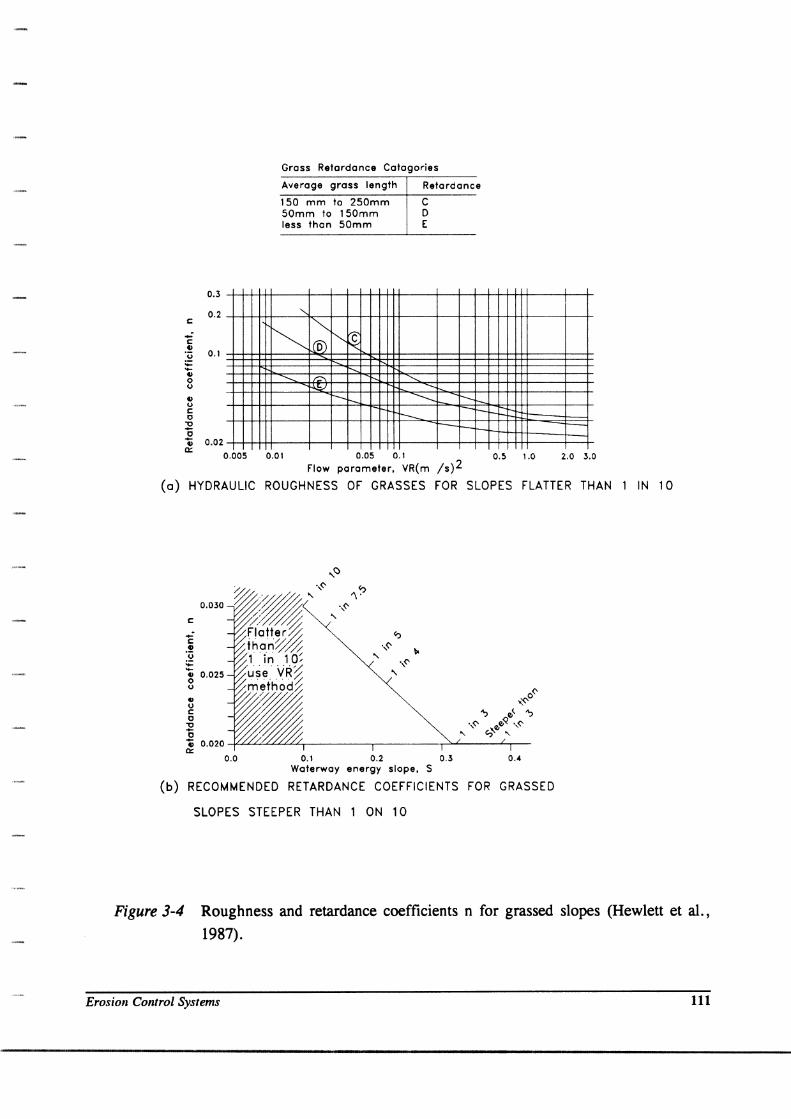
(i) Select an armor layer and a hydraulic roughness "n" value from Figure 3-4.
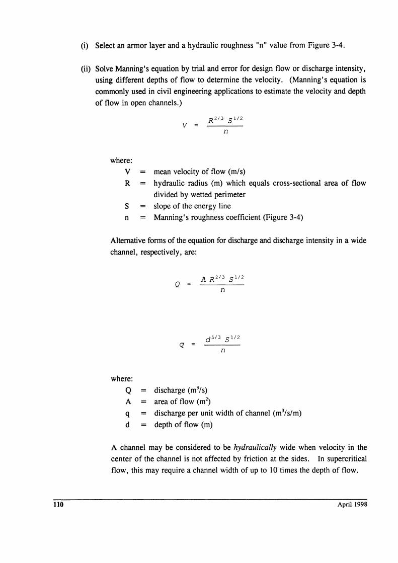
(ii) Solve Manning's equation by trial and error for design flow or discharge intensity,
using different depths of flow to determine the velocity. (Manning's equation is
commonly used in civil engineering applications to estimate the velocity and depth
of flow in open channels.)
v =
where:
V = mean velocity of flow (m/s)
R = hydraulic radius (m) which equals cross-sectional area of flow
divided by wetted perimeter
S = slope of the energy line
n = Manning's roughness coefficient (Figure 3-4)
Alternative forms of the equation for discharge and discharge intensity in a wide
channel, respectively, are:
Q =
q =
where:
A R2/3 5 1/2
n
Q = discharge (m3/s)
A = area of flow (m2)
q = discharge per unit width of channel (m3/s/m)
d = depth of flow (m)
A channel may be considered to be hydraulically wide when velocity in the
center of the channel is not affected by friction at the sides. In supercritical
flow, this may require a channel width of up to 10 times the depth of flow.
April 1998
c
c CI
0.3
0.2
'u 0.1 ~ -; o o CI o C o
"0
"0 ., 0.Q2 a::
0.005
Gross Retardance Catagories
Average gross length Retardance
150 mm to 250mm C SOmm to 150mm D less than 50mm E
"-
~ "" ~ lc l(5) r--<::
f'-,.
----r:::-. --.... ~
t--- I--
-------I--
t--- -r-t--- -
0.01 0.05 0.1 0.5 1.0 2.0 3.0
Flow parameter. VR(m /s)2
(0) HYDRAULIC ROUGHNESS OF GRASSES FOR SLOPES FLATTER THAN 1 IN 10
0.0 0.1 0.2 0.3 0.4 Waterway energy slope. S
(b) RECOMMENDED RETARDANCE COEFFICIENTS FOR GRASSED
SLOPES STEEPER THAN 1 ON 10
Figure 3-4 Roughness and retardance coefficients n for grassed slopes (Hewlett et aI.,
1987).
Erosion Colltroi Systems III
112
When uniform flow conditions have developed (i.e., terminal velocity is
reached), the energy slope, S; equals the slope of the channel bed. Depth of
uniform flow conditions is referred to as normal depth.
On steep slopes, the terminal velocity and normal blackwater depth calculated
using Manning's equation will normally be achieved. The normal blackwater depth may be converted to whitewaJer using the air voids ratio. For water flow
with a relatively small head loss between upstream and downstream energy
levels, normal depth may not be reached; a step-by-step method should be used
to determine the depth of flow and maximum velocity (Hewlett et al., 1987).
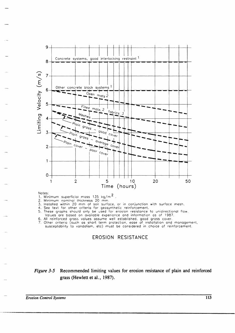
(iii) Compare this velocity with the recommended velocity for the armor layer from
Figure 3-5. If the recommended velocity is exceeded, it may be possible to
decrease the discharge intensity or select a more erosion-resistant armor layer.
If the velocity is less than that recommended, it may be possible to reduce the
base width or select a less erosion-resistant armor layer.
5. Determine the tailwater conditions over a range of discharges and consider ways to
dissipate energy at the toe of the waterway.
If the tailwater conditions cause a hydraulic jump to form on the slope (Figure 3-6, Case
(a», it may be advisable to provide heavier armor, stronger restraint, discharge, or
anchorage than normally used to protect the waterway from erosion by high-velocity
flow. The decision will depend on the energy loss and frequency of occurrence. The
critical zone of potential erosion is at the front of the jump. Experience from field trials
and embankment overtopping under high tailwater conditions has shown that high
velocity flow zones within the jump generally occur only at the front of the jump and that
erosion is consequently restricted.
If Cases (b), (c), or (d) in Figure 3-6 apply, provided the slope reinforcement is
terminated in a safe manner, limited erosion may be acceptable. Note that in all cases,
the flow velocity decreases downstream of the toe. Erosion protection may be provided -
either by continuing the slope reinforcement or by other means (e.g., gabion mattress,
rock armor).
If it is necessary to stabilize and contain the hydraulic jump -- for example, to
accommodate the short-term design discharge -- then a control and/or armored stilling
basin may be adopted.
April 1998
9 I I I I I I I I I
I I I I I I III 8
Concrete systems, good interlocking restraint 1
/"""-. II) 7
"'" E '--"
>- 6 -()
0 <D 5 > 0'> c 4 -E ~ 3
2
Other concrete block systems 1 --- ... o T J ~--f:'~S,_ -1- .. - Pilled I I ---- --- --- _ mots 2 ......... M r - .:.. - f~rics 3
i"~ .. ...... eshes - _1_ r-- ..... '------PI;;' -~ .. :- _~ ...... --- --. {;: -4..- gross -l- i" .. I- ~ ~--~ p. ~ -4:: - gOad ..... 10.. -- ..
~- --~ .......... 'Olf) gross _ +- Cover --Plain ~ _.,.: Overo'j- 4- .. -- .. "--I- .. i" .... cover .... f-.. cOve 1------ .,....~' POOr .......
~ . I- --. cover -~---- --o
2 5 Time
10 (hours)
20
Notes: 1. Minimum superficial moss 135 kg/m 2 2. Minimum nominal thickness 20 mm.
~- --1-- ---- ---- - ...
-- ---50
3. Installed within 20 mm of soil surface. or in conjunction with surface mesh. 4. See text for other criteria for geosynthetic reinforcement. S. These graphs should only be used for erosion resistance to unidirectional flow.
Values are based On available experiance and information as of 1987. 6. All reinforced graso> values assume well established. good grass caver. 7. Other criteria (such as short term protection. ease of installation and management.
susceptability to vandalism. etc) must be considered in choice af reinforcement.
EROSION RESISTANCE
Figure 3-5 Recommended limiting values for erosion resistance of plain and reinforced
grass (Hewlett et al., 1987).
Erosion Control Systems 113
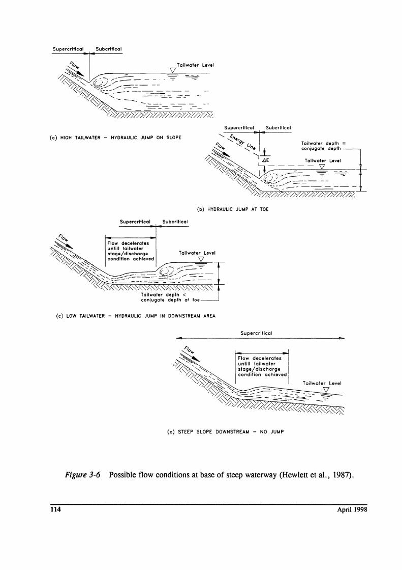
Supercrltlcal Subcrltlcal
Tailwoler Level
SZ
(a) HIGH TAILWATER - HYDRAULIC JUMP ON SLOPE
"""';1;001"1" ',bo,Hkol
(b) HYDRAULIC JUMP AT TOE
Supercriticol Subcritical
~"Ia ... ~ "-.I Flaw decelerates '\;.":'~ untill lailwater 0-~ "'.:...:: stage/discharge Tailwater Level
\~»> ~"'" 00";1;., ooh''''' 'V I '«~ ",~ , - -, .....--==----=-""~ ~ ..... ~, _~--- L'::.,/-- ----~ "", --------- -- ,""- --/~:~~i'\0:~/~~:i~"'~,,-:"''':'''~
Tailwater depth < conjugate depth at toe
(c) LOW TAILWATER - HYDRAULIC JUMP IN DOWNSTREAM AREA
... Supercrltlccl
(c) STEEP SLOPE DOWNSTREAM - NO JUMP
Figure 3-6 Possible flow conditions at base of steep waterway (Hewlett et aI., 1987).
114 April 1998
Geotechnical Considerations: The principal geotechnical consideration is the effect that water
entering the embankment (or excavation) will have on the subsoil. The procedure normally
followed is listed below. Consider the following principal points: (1) investigate the stability of
the slope during normal dry conditions, as well as during and immediately following flow; (2)
consider whether any localized drainage should be provided to provide relief of pore pressures for
increased stability; and (3) consider whether there is likely to be any settlement of the subsoil and
whether the armor layer is flexible enough to accommodate movement.
Botanical Considerations: Botanical considerations include the choice of grass mixture, and its
establishment and management. Consider the following principal points.
1. Obtain samples of soil that will support the grass and carry out physical and chemical
tests to determine its suitability.
2. Choose a grass mixture. The principal factors affecting this choice are soil conditions,
climate, and management requirements.
3. Decide on the method of sowing and establishment of grass.
Detailini and Specification: A number of detailed points should be considered which combine
the hydraulic, geotechnical, and botanical aspects, to complete the design process. These should
be included on the drawings or in the specification and are listed below.
1. Anchorage: Anchorage details of geosynthetic erosion control mats should be developed,
by the design engineer, on a project specific basis. Details include type and length of
anchorage pins or stakes, spacing of anchors across and along the edges the mat, roll end
anchorage, downslope shingling or anchorage of adjacent rolls, and anchorage at the top
of slope or embankment.
2. Crest Details: Complete a detailed design of the waterway or slope crest. The upstream
end of the reinforcement system must be designed to avoid the risk of waterway erosion
from the upstream area.
3. Channel Details: Cross-sections of the channel should be drawn. Estimate freeboard
based on bulked depth of flow. Careful detailing is required at any transition between
two or more plane surfaces.
4. Toe Details: Complete a detailed design of the toe of the waterway or slope.
S. Construction Details: Foundation preparation, transition to adjacent structures,
placement requirements, etc.
Details for each of these requirements are in Hewlett, et al. (1988). Remember to:
• check that the waterway will perform satisfactorily;
• produce the construction drawings;
• prepare a specification, including material and acceptance tests; and
• set up a framework for future construction, maintenance, and inspection.
Erosion COfllrol Systems 11S
It is important that adequate design and site supervision be exercised at all stages by the client or
its representative to ensure that the work is constructed in accordance with good practice.
3.11-3 Specification The following example specification for erosion control mats is after the Texas Department of
Transportation specification for RECPs. This agency tests candidate erosion control materials and
categorizes them into classes and types in an approved materials list.
SOIL EROSION CONTROL MATS (after Texas Department of Transportation, Special Specification, Item 1225 February 1993)
1. DESCRIPTION.
This item shall govern for providing and placing wood, straw, or coconut fiber mat, synthetic mat, jute mesh
or other material as a soil erosion control mat on slopes or ditches or for long-term protection of seeded areas
as shown on the plans or as specified by the Engineer.
2. MATERIALS.
116
(1) Soil Erosion Control Mats. All soil erosion control mats must be prequalified by the Director of
Maintenance and Operations prior to use.
Prequalification procedures and a current list of prequalified materials may be obtained by writing to the
Director of Maintenance and Operations. A 0.3 m x 0.3 m sample of the material may be required by the
Engineer in order to verify prequalification. Samples taken, accompanied by the manufacturer's literature,
will be sent, properly wrapped and identified, to the Division of Maintenance and Operations for
verification.
The soil erosion control mat shall be a Class 2 material and be one (1) of the following types as shown on
the plans:
Class 2. "ErosioQ Control Mat"
(i) Type E. Short-term duration (Up to 2 Years)
Shear Stress (td) < 50 Pa
(ii)
Prequalified Type E products are:
Type F. Short-term duration (Up to 2 Years)
Shear Stress (td) 50 to 95 Pa
April 1998
Prequalified Type F products are:
(iii) Type G. Long-term duration (Longer than 2 Years)
Shear Stress (td) > 95 to < 240 Pa
Prequalified Type G products are:
(iv) Type H. Long-term duration (Longer than 2 Years)
Shear Stress (td) greater than or equal to 240 Pa
Prequalified Type H products are:
(2) ~. Staples for anchoring the soil erosion control mat shall be U-shaped, made of 3 nun or large
diameter steel wire, or other approved material, have a width of 25 to 50 nun, and a length of not less than
150 nun for firm soils and not less than 300 mm for loose soils. [Longer staples, and closer spacings,
should be considered for steep reinforced soil slope applications.]
3. CONSTRUCTION METHODS.
(1) General. The soil erosion control mat shall conform to the class and type shown on the plans. The
Contractor has the option of selecting an approved soil erosion control mat conforming to the class and type
shown on the plans, and according to the current approved material list.
(2) Installation. The soil erosion control mat, whether installed as slope protection or as flexible channel liner
in accordance with the approved materials list, shall be placed within 24 hours after seeding or sodding
operations have been completed, or as approved by the Engineer. Prior to placing the mat, the area to be
covered shall be relatively free of all rocks or clods over I-Ill inches in maximum dimension and all sticks
or other foreign material which will prevent the close contact of the mat with the soil. The area shall be
smooth and free of ruts or depressions exist for any reason, the Contractor shall be required to rework the
soil until it is smooth and to reseed or resod the area at the Contractor's expense.
Installation and anchorage of the soil erosion control mat shall be in accordance with the project
construction drawings unless otherwise specified in the contract or directed by the Engineer.
(3) Literature. The Contractor shall submit one (1) full set of manufacturer's literature and manufacturer's
installation recommendations for the soil erosion control mat selected in accordance with the approved
material list.
Erosion Control Systems 117
4. MEASUREMENT.
This Item will be measured by the square meter of surface area covered.
5. PAYMENT.
The work performed and materials furnished in accordance with this Item and measured as provided under
"Measurement" will be paid for at the unit price bid for "Soil Erosion Control Mat" of the class and type shown
on the plans. This price shall be full compensation for furnishing all materials, labor, tools, equipment and
incidentals necessary to complete the work. Anchors, checks, terminals or junction slots, and wire staples or
wood stakes will not be paid for directly but will be considered subsidiary to this Item.
3.12 REFERENCES
AASHTO, Standard Specifications for Geotextiles - M 288, Standard Specificatiom for Tramp0rtation Materials and Methom of Sampling and Te;ting, 18111 Edition, American Association of State Tramportation and Highway Officials, Washington, D.C., 1997.
AASHTO, Model Draina~ Manual, 1st Ed., American Association of State Highway and Transportation Officials, Washington, D.C., 1991.
AASHTO, Task Force 25 Report - Guide Specifications and Test Procedures for Geotextiles, Subcommittee on New Highway Materials, American Association of State Transportation and Highway Officials, Washington, D.C., 1990.
ASTM (1997), Soil and Rock (II): D 4943 -latest,' Geosynthetics, Annual Book of ASTM Standards, Section 4, Volume 04.09, American Society for Testing and Materials, West Conshohocken, PA, 1246 p.
ASTM Test Methods - see Appendix E.
Cedergren, H.R., Seepa~. Draina~. and Flow Nets, Third Edition, John Wiley and Sons, New York, 1989, 465p.
Christopher, B.R. and Holtz, R.D., Geotextile Em:ipeerln& Manual, Report No. FHWA-TS-86/203, Federal Highway Administration, Washington, D.C., Mar 1985, 1044 p.
Dunham, J.W. and Barrett, R.J. (1974), Woven Plastic Cloth Filtersfor Stone Seawalls, Journal of the Waterways. Harbors. and Coastal EP&iPeerip& Divisiop, American Society of Civil Engineers, New York, February.
FHWA, Bridge Scour and Stream Instability Countermeasures, Hydraulic EP&iPeerip& Circular No. 23, Federal Highway Administration, FHWA HI-97-030, 1997.
FHW A, Evaluation Scour at Bridges, Hydraulic Ep~P& Circular No. 18, Federal Highway Administration IP-90-017, 1995.
FHWA, Design of Rip rap Revetment, Hydraulic Ep&iPeerip& Circular No. 11, Federal Highway Administration, 1989.
FHWA, Design of Roadside Channels with Flexible Li1lings, Hydraulic En&ineerip& Circular No. 15, Federal Highway Administration, 1988.
FHW A, Hydraulic Design of Energy Dissipators for Culvert and Channels, Hydraulic EP&ineerip& Circular No. 14, Federal Highway Administration, 1983.
118 April 1998
Hewlett, H.W.M., Boonnan, L.A. and Bramley, M.E., Design of Reinforced Grass Waterways - Report 116, Construction Industry Research and Infonnation Association, London, U.K., 1987, 116 p.
HydroDynamics Incorporated, ldentifyinl: and Controllinl: Erosjon and Sedjmentatjon, FHWA Project No. DTFH61-C-97-OOO13, U.S. Department of Transportation, Federal Highway Administration, Washington, D.C., Nov 1997, DRAFT, 264 p.
Keown, M.P. and Dardeau, E.A., Jr. (1980), Utilization of Filter Fabricfor Streambank Protection Applications, TR HL-80-12, Hydraulics Laboratory, U.S. Army Engineer Waterways Experiment Station, Vicksburg, MS.
Koerner, R.M., Designing With Geosynthetics, 3rd Edition, Prentice-Hall Inc., Englewood Cliffs, NJ, 1994, 783 p.
U.S. Army Corps of Engineers, Civil Works' Construction Guide Specification for Plastic Filter Fabric, Corps of Engineer Specifications No. CW-02215, Office, Chief of Engineers, U.S. Army Corps of Engineers, Washington, D.C., 1977.
U.S. Department of the Navy, Foundations and Earth Structures, Desjl:n Manual 7.2, Naval Facilities Engineering Command, Alexandria, VA, 1982.
U. S. Department of the Navy, Soil Mechanics, Desjl:n Manual 7.1, Naval Facilities Engineering Command, Alexandria, VA, 1982.
Erosion Control Systems 119
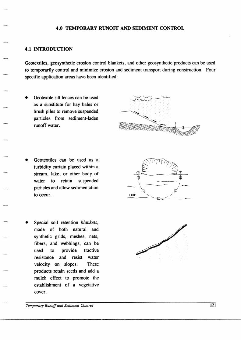
4.0 TEMPORARY RUNOFF AND SEDIMENT CONTROL
4.1 INTRODUCTION
Geotextiles, geosynthetic erosion control blankets, and other geosynthetic products can be used
to temporarily control and minimize erosion and sediment transport during construction. Four
specific application areas have been identified:
• Geotextile silt fences can be used as a substitute for hay bales or
brush piles to remove suspended
particles from sediment-laden
runoff water.
• Geotextiles can be used as a turbidity curtain placed within a
stream, lake, or other body of
water to retain suspended
particles and allow sedimentation
to occur.
• Special soil retention blankets,
made of both natural and
synthetic grids, meshes, nets,
fibers, and webbings, can be
used to provide tractive
resistance and resist water
velocity on slopes. These
products retain seeds and add a
mulch effect to promote the
establishment of a vegetative
cover.
Temporary Runoff and Sediment C01llrol
\ ----------- / - ~--- ;f--LAKE" /' -- ...... -El--::..--"---
121
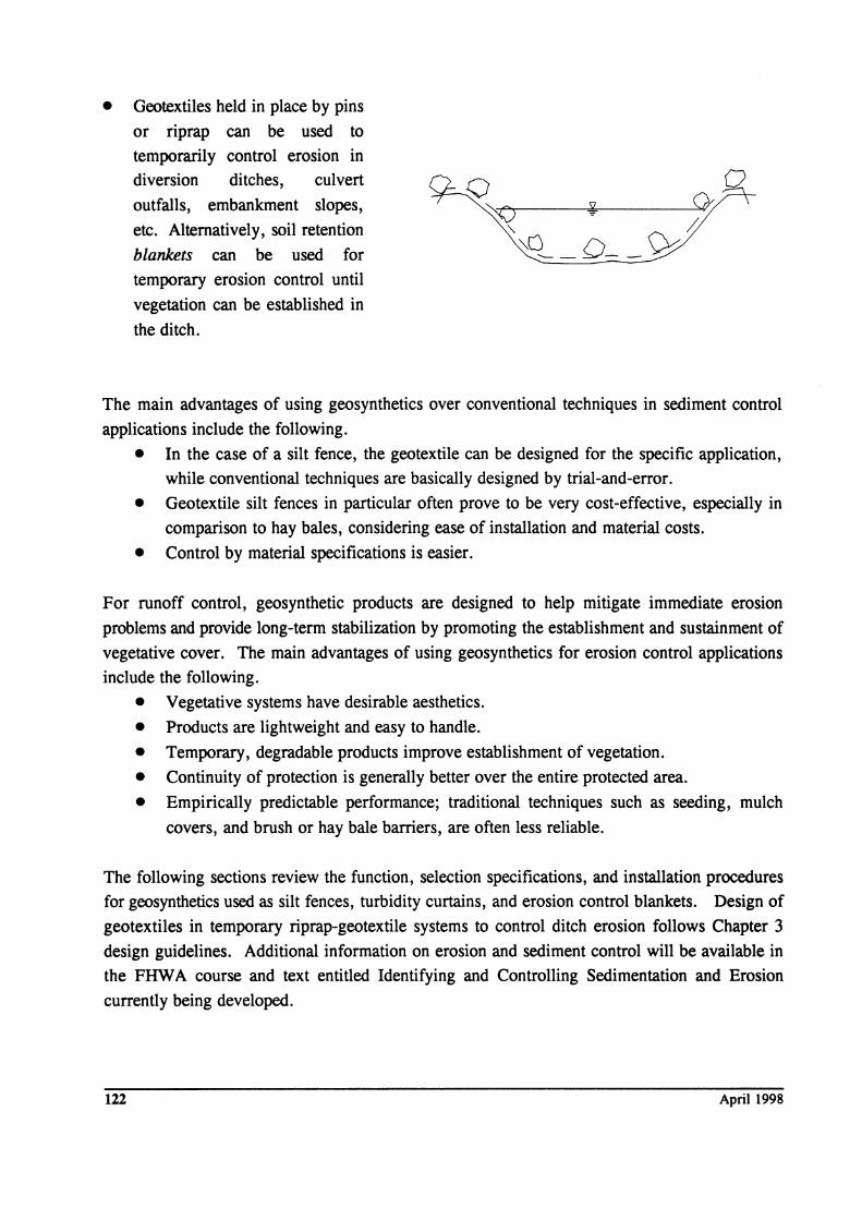
• Geotextiles held in place by pins
or riprap can be used to
temporarily control erosion in diversion ditches, culvert
outfalls, embankment slopes,
etc. Alternatively, soil retention
blankets can be used for
temporary erosion control until
vegetation can be established in
the ditch.
The main advantages of using geosynthetics over conventional techniques in sediment control
applications include the following.
• In the case of a silt fence, the geotextile can be designed for the specific application, while conventional techniques are basically designed by trial-and-error.
• Geotextile silt fences in particular often prove to be very cost-effective, especially in
comparison to hay bales, considering ease of installation and material costs.
• Control by material specifications is easier.
For runoff control, geosynthetic products are designed to help mitigate immediate erosion
problems and provide long-term stabilization by promoting the establishment and sustainment of
vegetative cover. The main advantages of using geosynthetics for erosion control applications
include the following.
• Vegetative systems have desirable aesthetics.
• Products are lightweight and easy to handle.
• Temporary, degradable products improve establishment of vegetation.
• Continuity of protection is generally better over the entire protected area.
• Empirically predictable performance; traditional techniques such as seeding, mulch
covers, and brush or hay bale barriers, are often less reliable.
The following sections review the function, selection specifications, and installation procedures
for geosynthetics used as silt fences, turbidity curtains, and erosion control blankets. Design of
geotextiles in temporary riprap-geotextile systems to control ditch erosion follows Chapter 3
design guidelines. Additional information on erosion and sediment control will be available in
the FHW A course and text entitled Identifying and Controlling Sedimentation and Erosion
currently being developed.
122 April 1998
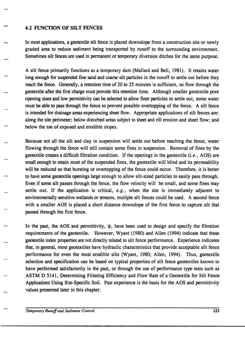
4.2 FUNCTION OF SILT FENCES
In most applications, a geotextile silt fence is placed downslope from a construction site or newly
graded area to reduce sediment being transported by runoff to the surrounding environment.
Sometimes silt fences are used in permanent or temporary diversion ditches for the same purpose.
A silt fence primarily functions as a temporary dam (Mallard and Bell, 1981). It retains water
long enough for suspended fine sand and coarse silt particles in the runoff to settle out before they
reach the fence. Generally, a retention time of 20 to 25 minutes is sufficient, so flow through the
geotextile after the first charge must provide this retention time. Although smaller geotextile pore
opening sizes and low permittivity can be selected to allow finer particles to settle out, some water
must be able to pass through the fence to prevent possibl~ overtopping of the fence. A silt fence
is intended for drainage areas experiencing sheet flow. Appropriate applications of silt fences are:
along the site perimeter; below disturbed areas subject to sheet and rill erosion and sheet flow; and
below the toe of exposed and erodible slopes.
Because not all the silt and clay in suspension will settle out before reaching the fence, water
flowing through the fence will still contain some fines in suspension. Removal of fines by the
geotextile creates a difficult filtration condition. If the openings in the geotextile (i. e., ADS) are
small enough to retain most of the suspended fines, the geotextile will blind and its permeability
will be reduced so that bursting or overtopping of the fence could occur. Therefore, it is better
to have some geotextile openings large enough to allow silt-sized particles to easily pass through.
Even if some silt passes through the fence, the flow velocity will be small, and some fines may
settle out. If the application is critical, e.g., when the site is immediately adjacent to
environmentally sensitive wetlands or streams, multiple silt fences could be used. A second fence
with a smaller ADS is placed a short distance downslope of the first fence to capture silt that
passed through the first fence.
In the past, the ADS and permittivity, lJ1, have been used to design and specify the filtration
requirements of the geotextile. However, Wyant (1980) and Allen (1994) indicate that these
geotextile index properties are not directly related to silt fence performance. Experience indicates
that, in general, most geotextiles have hydraulic characteristics that provide acceptable silt fence
performance for even the most erodible silts (Wyant, 1980; Allen, 1994). Thus, geotextile
selection and specification can be based on typical properties of silt fence geotextiles known to
have performed satisfactorily in the past, or through the use of performance type tests such as
ASTM D 5141, Determining Filtering Efficiency and Flow Rate of a Geotextile for Silt Fence
Applications Using Site-Specific Soil. Past experience is the basis for the ADS and permittivity
values presented later in this chapter.
Temporary Runoff and Sedimelll Control 123
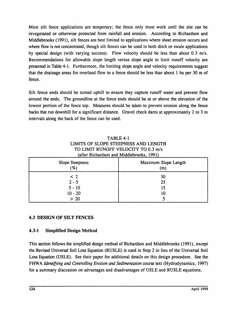
Most silt fence applications are temporary; the fence only must work until the site can be
revegetated or otherwise protected from rainfall and erosion. According to Richardson and
Middlebrooks (1991), silt fences are best limited to applications where sheet erosion occurs and
where flow is not concentrated, though silt fences can be used in both ditch or swale applications
by special design (with varying success). Flow velocity should be less than about 0.3 m/s. Recommendations for allowable slope length versus slope angle to limit runoff velocity are
presented in Table 4-1. Furthermore, the limiting slope angle and velocity requirements suggest
that the drainage areas for overland flow to a fence should be less than about 1 ha per 30 m of
fence.
Silt fence ends should be turned uphill to ensure they capture runoff water and prevent flow
around the ends. The groundline at the fence ends should be at or above the elevation of the
lowest portion of the fence top. Measures should be taken to prevent erosion along the fence
backs that run downhill for a significant distance. Gravel check dams at approximately 2 to 3 m
intervals along the back of the fence can be used.
TABLE 4-1 LIMITS OF SLOPE STEEPNESS AND LENGTH
TO LIMIT RUNOFF VELOCITY TO 0.3 mls (after Richardson and Middlebrooks, 1991)
Slope Steepness Maximum Slope Length (%) (m)
< 2 30 2-5 25 5 - 10 15
10 - 20 10 > 20 5
4.3 DESIGN OF SILT FENCES
4.3-1 Simplified Design Method
This section follows the simplified design method of Richardson and Middlebrooks (1991), except
the Revised Universal Soil Loss Equation (RUSLE) is used in Step 2 in lieu of the Universal Soil
Loss Equation (USLE). See their paper for additional details on this design procedure. See the
FHWA Identifying and Controlling Erosion and Sedimentation course text (Hydrodynamics, 1997)
for a summary discussion on advantages and disadvantages of USLE and RUSLE equations.
124 April 1998
STEP 1. Estimate runoff volume.
Use the Rational Method (small watershed areas):
Q = 2.8 x 10⁻³ CiA [4 - 1]
where:
Q = runoff (m3/s)
C = surface runoff coefficient
1 = rainfall intensity (mm/hr)
A = area (ha)
Use C = 0.2 for rough surfaces, and C = 0.6 for smooth surfaces. A lO-year storm event
is typically used for designing silt fences.
Use the appropriate rainfall intensity factor, i, for the locality. Assume a lO-year design
storm, or use local design regulations. Neglect any concentration times (worst case). This
calculation gives the total storage volume required of the silt fence.
STEP 2. Estimate sediment volume.
Use the Revised Universal Soil Loss Equation (RUSLE)
where:
A -R -K =
LS -C =
P -
A = 2.2 R K (LS) C P
annual soil loss due to erosion (metric tons/ha/yr)
rainfall factor
soil erodibility factor
slope length and steepness factor
vegetative cover factor C> = 1 for no cover)
erosion control practice factor (P = 1 for minimal practice)
[4 - 2]
Obtain rainfall erosion index from Figure 4-1; note that the factors are based upon a 2-year,
6-hour storm event. Use Figure 4-2 to obtain the values of KLS (limited slope lengths and
steepness factors are applicable to most silt fence applications).
Temporary Runoff and Sediment Control 125
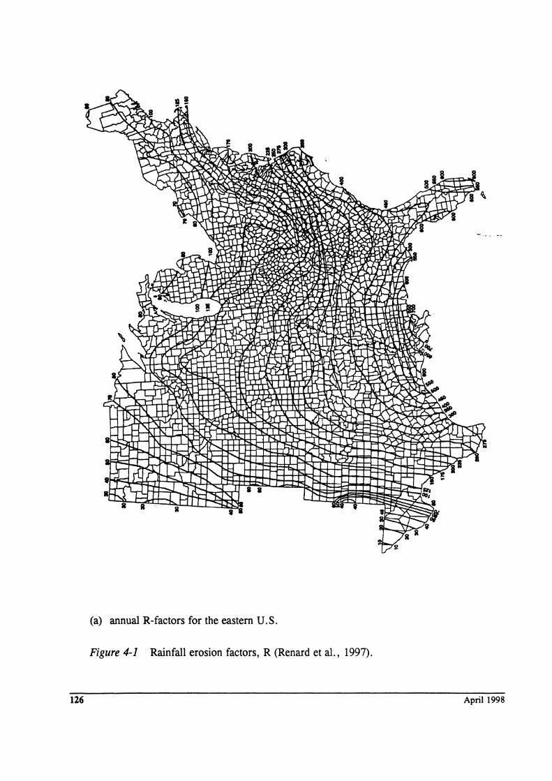
(a) annual R-factors for the eastern U.S.
Figure 4-1 Rainfall erosion factors, R (Renard et aI., 1997).
126 April 1998
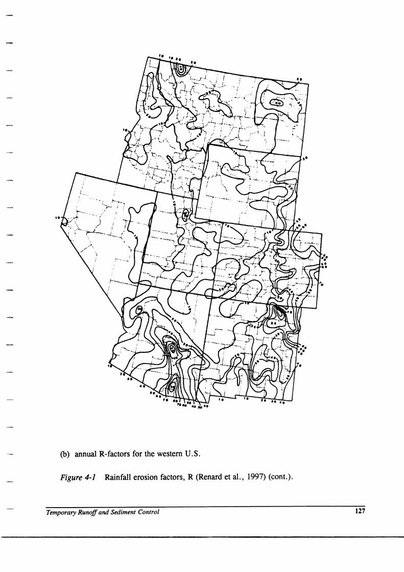
(b) annual R-factors for the western U.S.
Figure 4-1 Rainfall erosion factors, R (Renard et al., 1997) (cont.).
Temporary Runoff and Sediment Control 127
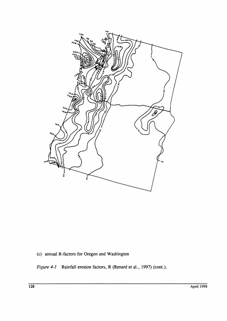
(c) annual R-factors for Oregon and Washington
Figure 4-1 Rainfall erosion factors, R (Renard et aI., 1997) (cont.).
128 April 1998
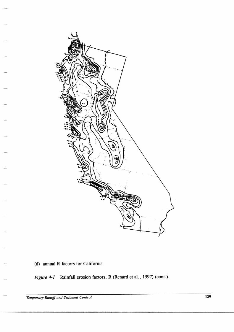
(d) annual R-factors for California
Figure 4-1 Rainfall erosion factors, R (Renard et al., 1997) (cont.).
Temporary Runoff and Sediment Control 129
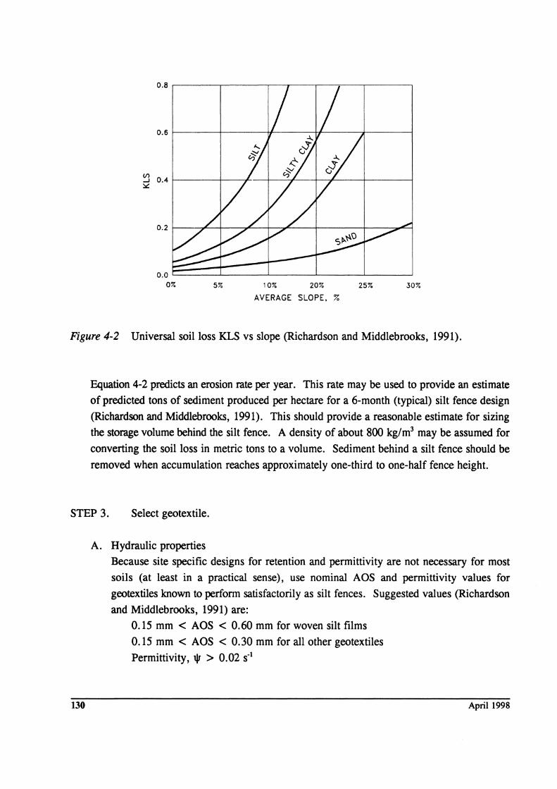
0.8 ,------.-----.-----.--,--------.---.-----,
0.6f-----+---~---~-----+--~
~ 0.4 f-----+--+--+----.f-----+---,f----+-------l ~
0.0 ~~±==::t==_L_~_~ 0% 5% 10% 20% 25% 30%
AVERAGE SLOPE. %
Figure 4-2 Universal soil loss KLS vs slope (Richardson and Middlebrooks, 1991).
Equation 4-2 predicts an erosion rate per year. This rate may be used to provide an estimate
of predicted tons of sediment produced per hectare for a 6-month (typical) silt fence design
(Richardson and Middlebrooks, 1991). This should provide a reasonable estimate for sizing
the storage volume behind the silt fence. A density of about 800 kg/m3 may be assumed for
converting the soil loss in metric tons to a volume. Sediment behind a silt fence should be
removed when accumulation reaches approximately one-third to one-half fence height.
STEP 3. Select geotextile.
130
A. Hydraulic properties
Because site specific designs for retention and permittivity are not necessary for most
soils (at least in a practical sense), use nominal AOS and permittivity values for
geotextiles known to perform satisfactorily as silt fences. Suggested values (Richardson
and Middlebrooks, 1991) are:
0.15 mm < AOS < 0.60 mm for woven silt films
0.15 mm < AOS < 0.30 mm for all other geotextiles
Permittivity, tV > 0.02 S-1
April 1998
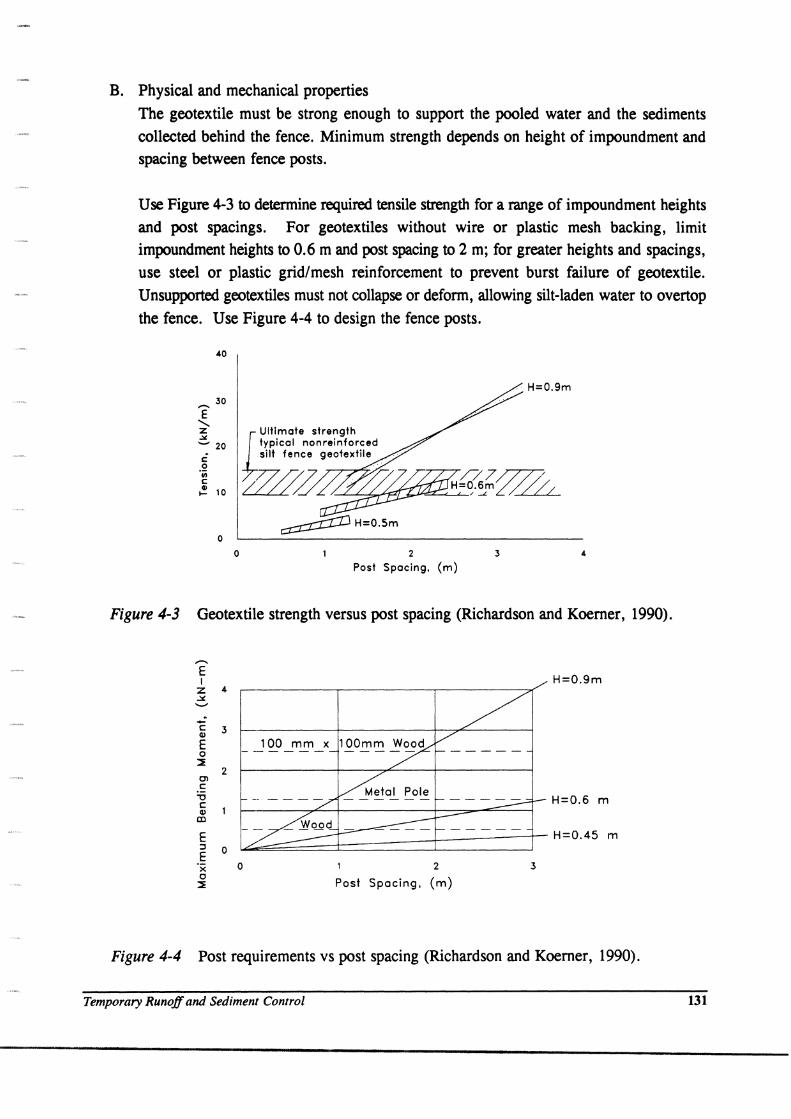
B. Physical and mechanical properties The geotextile must be strong enough to support the pooled water and the sediments collected behind the fence. Minimum strength depends on height of impoundment and spacing between fence posts.
Use Figure 4-3 to determine required tensile strength for a range of impoundment heights and post spacings. For geotextiles without wire or plastic mesh backing, limit impoundment heights to 0.6 m and post spacing to 2 m; for greater heights and spacings, use steel or plastic grid/mesh reinforcement to prevent burst failure of geotextile. Unsupported geotextiles must not collapse or deform, allowing silt-laden water to overtop the fence. Use Figure 4-4 to design the fence posts.
E ........ z ~
40
30
........ 20
c o 'iii c .! 10
o o
Ultimate strength typical nonreinforced silt fence geotextile
2
Post Spacing. {m}
H=O.9m
3
Figure 4-3 Geotextile strength versus post spacing (Richardson and Koerner, 1990).
-. E I
Z 4 ,:,t. '-"
'E 3 <II
E o :l!
E j 0 E x o
::l!
H=0.9m
100 mm x
H=0.6 m
~~::;;;;;;;;±======::J=====r H=0.45 m
o 2
Post Spacing. (m) 3
Figure 4-4 Post requirements vs post spacing (Richardson and Koerner, 1990).
Temporary Runoff and Sediment Control 131
4.3-2 Alternate Hydraulic Design Using Perfonnance Tests
An alternate design approach for silt fences uses model studies to estimate filtration efficiency for
specific site conditions. This method was developed by Wyant (1980) for the Virginia Highway
and Transportation Research Council (VHTRC) and is based on observed field performance and
laboratory testing. The procedures for this method are described in ASTM D 5141. The
laboratory model consists of a flume with an outflow opening similar to the size of a hay bale and
positioned at a fixed slope of 8%. The geotextile is strapped across the end of the flume. A
representative soil sample from the site is then suspended in water to a concentration of about
3000 ppm (equivalent water content is 0.3 percent) and poured through the flume. Based on the
performance of the geotextile, appropriate geotextiles can be selected to provide filtering
efficiencies approximating of 75 % or more and flow rates on the order of 0.1 L/min/m2 after
three test repetitions.
The model study approach provides a system performance evaluation by utilizing actual soils from
the local area of interest. Thus, it cannot be performed by manufacturers. The approach lends
itself to an approved list-type specification for silt fences. In this case, the agency or its
representatives perform th~ flume test using their particular problem soils and prequalifies the
geotextiles that meet filtering efficiency and flow criteria requirements. Qualifying geotextiles
can be placed on an approved list that is then provided to contractors. Geotextiles on any
approved list should be periodically retested because manufacturing changes often occur.
4.3-3 Constructability Requirements
The geotextile used as a silt fence must be strong enough to enable it to be properly installed.
AASHTO M288 property recommendations are indicated in Table 4-2. Realize that these
specifications are not based on research but on properties of existing geotextiles which have
performed satisfactorily in silt fence applications. Also given are requirements for resistance to
ultraviolet degradation. Although the applications are temporary (e.g., 6 to 36 months), the
geotextile must have sufficient UV resistance to function throughout its anticipated design life.
132 April 1998
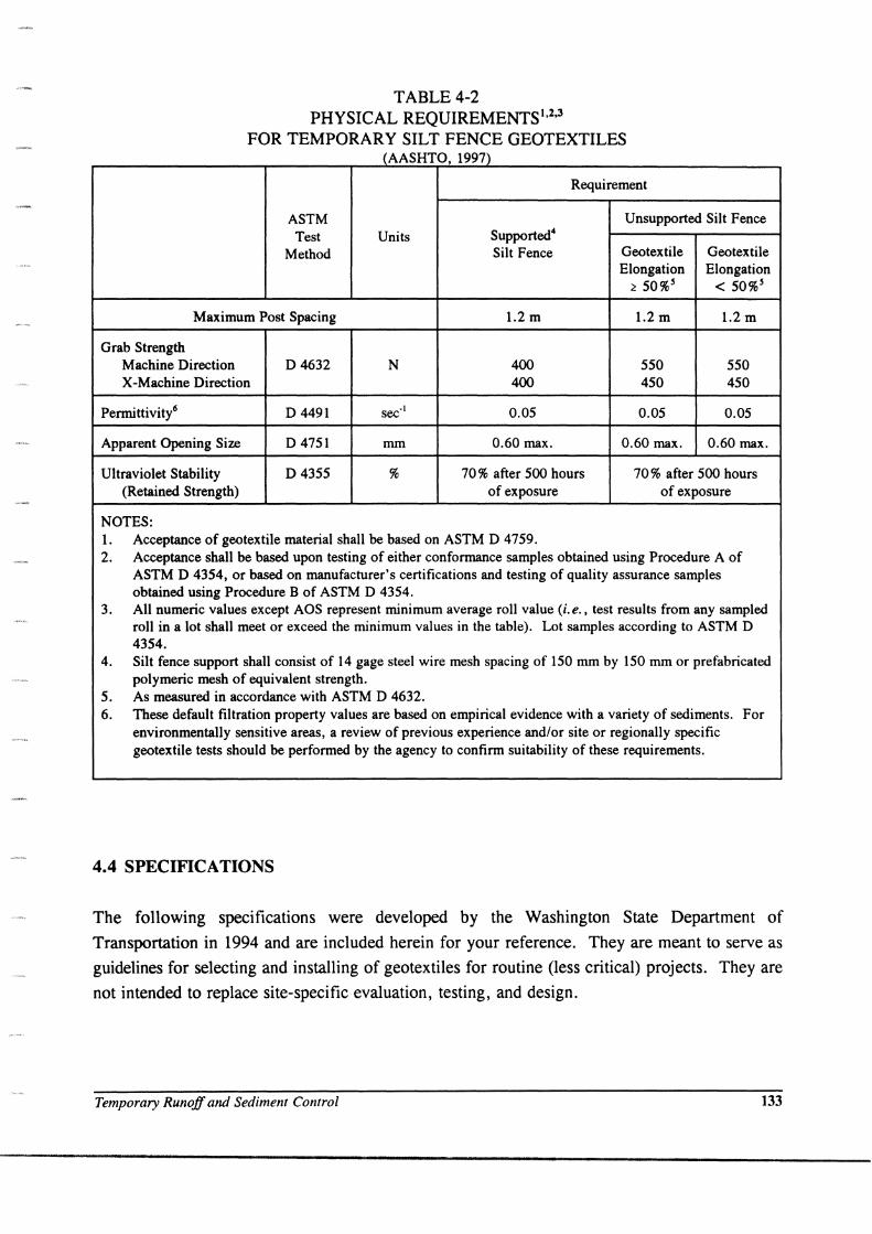
TABLE 4-2 PHYSICAL REQUIREMENTS 1,2,3
FOR TEMPORARY SILT FENCE GEOTEXTILES (AASHTO, 1997)
Requirement
ASTM Unsupported Silt Fence Test Units Supported4
Method Silt Fence Geotextile Geotextile Elongation Elongation
:2 50%5 < 50%5
Maximum Post Spacing 1.2 m 1.2 m 1.2 m
Grab Strength Machine Direction D4632 N 400 550 550 X-Machine Direction 400 450 450
Permittivity6 D4491 sec' \ 0.05 0.05 0.05
Apparent Opening Size D 4751 mm 0.60 max. 0.60 max. 0.60 max.
Ultraviolet Stability D4355 % 70 % after 500 hours 70 % after 500 hours (Retained Strength) of exposure of exposure
NOTES: 1. Acceptance of geotextile material shall be based on ASTM D 4759. 2. Acceptance shall be based upon testing of either conformance samples obtained using Procedure A of
ASTM D 4354, or based on manufacturer's certifications and testing of quality assurance samples obtained using Procedure B of ASTM D 4354.
3. All numeric values except AOS represent minimum average roll value (i.e., test results from any sampled roll in a lot shall meet or exceed the minimum values in the table). Lot samples according to ASTM D 4354.
4. Silt fence support shall consist of 14 gage steel wire mesh spacing of 150 mm by 150 mm or prefabricated polymeric mesh of equivalent strength.
5. As measured in accordance with ASTM D 4632. 6. These default filtration property values are based on empirical evidence with a variety of sediments. For
environmentally sensitive areas, a review of previous experience and/or site or regionally specific geotextile tests should be performed by the agency to confirm suitability of these requirements.
4.4 SPECIFICATIONS
The following specifications were developed by the Washington State Department of
Transportation in 1994 and are included herein for your reference. They are meant to serve as
guidelines for selecting and installing of geotextiles for routine (less critical) projects. They are
not intended to replace site-specific evaluation, testing, and design.
Temporary Runoff and Sediment Control 133
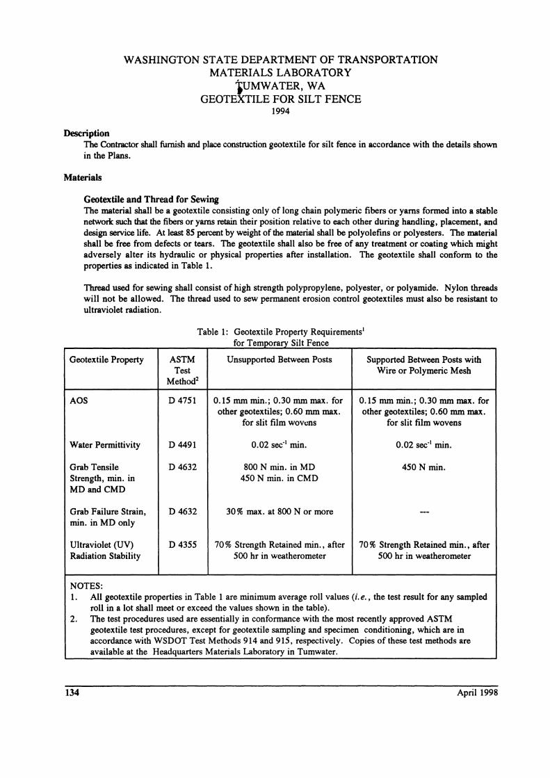
WASHINGTON STATE DEPARTMENT OF TRANSPORTATION MATERIALS LABORATORY
iUMWATER, WA GEOTEXTILE FOR SILT FENCE
1994
Description The Contractor shall furnish and place construction geotextile for silt fence in accordance with the details shown in the Plans.
Materials
Geotextile and Thread for Sewing The material shall be a geotextile consisting only of long chain polymeric fibers or yams formed into a stable network such that the fibers or yams retain their position relative to each other during handling, placement, and design service life. At least 85 percent by weight of the material shall be polyolefins or polyesters. The material shall be free from defects or tears. The geotextile shall also be free of any treatment or coating which might adversely alter its hydraulic or physical properties after installation. The geotextile shall conform to the properties as indicated in Table 1.
Thread used for sewing shall consist of high strength polypropylene, polyester, or polyamide. Nylon threads will not be allowed. The thread used to sew permanent erosion control geotextiles must also be resistant to ultraviolet radiation.
Geotextile Property
AOS
Water Permittivity
Grab Tensile Strength, min. in MDandCMD
Grab Failure Strain, min. in MD only
Ultraviolet (UV) Radiation Stability
NOTES:
Table 1: Geotextile Property Requirements' for Temporary Silt Fence
ASTM Test
Method2
D4751
D 4491
D 4632
D4632
D4355
Unsupported Between Posts
0.15 mm min.; 0.30 mm max. for other geotextiles; 0.60 mm max.
for slit film wowns
0.02 sec-' min.
800 N min. in MD 450 N min. in CMD
30% max. at 800 N or more
70 % Strength Retained min., after 500 hr in weatherometer
Supported Between Posts with Wire or Polymeric Mesh
0.15 mm min.; 0.30 mm max. for other geotextiles; 0.60 mm max.
for slit film wovens
0.02 sec-' min.
450 N min.
70% Strength Retained min., after 500 hr in weatherometer
1. All geotextile properties in Table 1 are minimum average roll values (i. e., the test result for any sampled roll in a lot shall meet or exceed the values shown in the table).
2. The test procedures used are essentially in conformance with the most recently approved ASTM geotextile test procedures, except for geotextile sampling and specimen conditioning, which are in accordance with WSDOT Test Methods 914 and 915, respectively. Copies of these test methods are available at the Headquarters Materials Laboratory in Tumwater.
134 April 1998
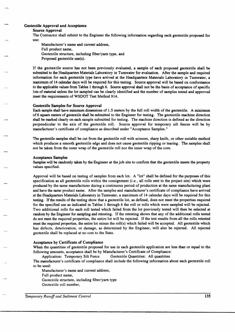
Geotextile Approval and Acceptance Source Approval The Contractor shall submit to the Engineer the following information regarding each geotextile proposed for use:
Manufacturer's name and current address, Full product name, Geotextile structure, including fiber/yam type, and Proposed geotextile use(s).
If the geotextile source has not been previously evaluated, a sample of each proposed geotextile shall be submitted to the Headquarters Materials Laboratory in Tumwater for evaluation. After the sample and required information for each geotextile type have arrived at the Headquarters Materials Laboratory in Tumwater, a maximum of 14 calendar days will be required for this testing. Source approval will be based on conformance to the applicable values from Tables 1 through 6. Source approval shall not be the basis of acceptance of specific lots of material unless the lot sampled can be clearly identified and the number of samples tested and approved meet the requirements ofWSDOT Test Method 914.
Geotextile Samples for Source Approval Each sample shall have minimum dimensions of 1.5 meters by the full roll width of the geotextile. A minimum of 6 square meters of geotextile shall be submitted to the Engineer for testing. The geotextile machine direction shall be marked clearly on each sample submitted for testing. The machine direction is defined as the direction perpendicular to the axis of the geotextile roll. Source approval for temporary silt fences will be by manufacturer's certificate of compliance as described under" Acceptance Samples. "
The geotextile samples shall be cut from the geotextile roll with scissors, sharp knife, or other suitable method which produces a smooth geotextile edge and does not cause geotextile ripping or tearing. The samples shall not be taken from the outer wrap of the geotextile roll nor the inner wrap of the core.
Acceptance Samples Samples will be randomly taken by the Engineer at the job site to confirm that the geotextile meets the property values specified.
Approval will be based on testing of samples from each lot. A "lot" shall be defined for the purposes of this specification as all geotextile rolls within the consignment (i.e., all rolls sent to the project site) which were produced by the same manufacturer during a continuous period of production at the same manufacturing plant and have the same product name. After the samples and manufacturer's certificate of compliance have arrived at the Headquarters Materials Laboratory in Tumwater, a maximum of 14 calendar days will be required for this testing. If the results of the testing show that a geotextile lot, as defined, does not meet the properties required for the specified use as indicated in Tables 1 through 6 the roll or rolls which were sampled will be rejected. Two additional rolls for each roll tested which failed from the lot previously tested will then be selected at random by the Engineer for sampling and retesting. If the retesting shows that any of the additional rolls tested do not meet the required properties, the entire lot will be rejected. If the test results from all the rolls retested meet the required properties, the entire lot minus the roll(s) which failed will be accepted. All geotextile which has defects, deterioration, or damage, as determined by the Engineer, will also be rejected. All rejected geotextile shall be replaced at no cost to the State.
Acceptance by Certificate of Compliance When the quantities of geotextile proposed for use in each geotextile application are less than or equal to the following amounts, acceptance shall be by Manufacturer's Certificate of Compliance:
Application: Temporary Silt Fence Geotextile Quantities: All quantities The manufacturer's certificate of compliance shall include the following information about each geotextile roll to be used:
Manufacturer's name and current address, Full product name, Geotextile structure, including fiber/yam type Geotextile roll number,
Temporary Runoff and Sedimem Control 135
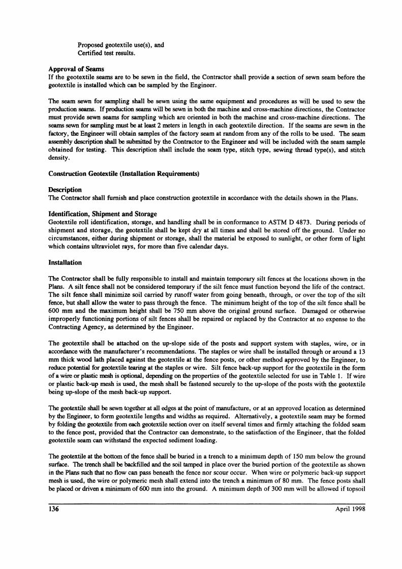
Proposed geotextile use(s), and Certified test results.
Approval of Seams If the geotextile seams are to be sewn in the field, the Contractor shall provide a section of sewn seam before the geotextile is installed which can be sampled by the Engineer.
The seam sewn for sampling shall be sewn using the same equipment and procedures as will be used to sew the production seams. If production seams will be sewn in both the machine and cross-machine directions, the Contractor must provide sewn seams for sampling which are oriented in both the machine and cross-machine directions. The seams sewn for sampling must be at least 2 meters in length in each geotextile direction. If the seams are sewn in the factory, the Engineer will obtain samples of the factory seam at random from any of the rolls to be used. The seam assembly description shall be submitted by the Contractor to the Engineer and will be included with the seam sample obtained for testing. This description shall include the seam type, stitch type, sewing thread type(s), and stitch density.
Construction Geotextile (Installation Requirements)
Description TIle Contractor shall furnish and place construction geotextile in accordance with the details shown in the Plans.
Identification, Shipment and Storage Geotextile roll identification, storage, and handling shall be in conformance to ASTM D 4873. During periods of shipment and storage, the geotextile shall be kept dry at all times and shall be stored off the ground. Under no circumstances, either during shipment or storage, shall the material be exposed to sunlight, or other form of light which contains ultraviolet rays, for more than five calendar days.
Installation
The Contractor shall be fully responsible to install and maintain temporary silt fences at the locations shown in the Plans. A silt fence shall not be considered temporary if the silt fence must function beyond the life of the contract. The silt fence shall minimize soil carried by runoff water from going beneath, through, or over the top of the silt fence, but shall allow the water to pass through the fence. The minimum height of the top of the silt fence shall be 600 mm and the maximum height shall be 750 mm above the original ground surface. Damaged or otherwise improperly functioning portions of silt fences shall be repaired or replaced by the Contractor at no expense to the Contracting Agency, as determined by the Engineer.
The geotextile shall be attached on the up-slope side of the posts and support system with staples, wire, or in accordance with the manufacturer's recommendations. The staples or wire shall be installed through or around a 13 mm thick wood lath placed against the geotextile at the fence posts, or other method approved by the Engineer, to reduce potential for geotextile tearing at the staples or wire. Silt fence back-up support for the geotextile in the form of a wire or plastic mesh is optional, depending on the properties of the geotextile selected for use in Table 1. If wire or plastic back-up mesh is used, the mesh shall be fastened securely to the up-slope of the posts with the geotextile being up-slope of the mesh back-up support.
The geotextile shall be sewn together at all edges at the point of manufacture, or at an approved location as determined by the Engineer, to form geotextile lengths and widths as required. Alternatively, a geotextile seam may be formed by folding the geotextile from each geotextile section over on itself several times and firmly attaching the folded seam to the fence post, provided that the Contractor can demonstrate, to the satisfaction of the Engineer, that the folded geotextile seam can withstand the expected sediment loading.
The geotextile at the bottom of the fence shall be buried in a trench to a minimum depth of 150 mm below the ground surface. The trench shall be backfilled and the soil tamped in place over the buried portion of the geotextile as shown in the Plans such that no flow can pass beneath the fence nor scour occur. When wire or polymeric back-up support mesh is used, the wire or polymeric mesh shall extend into the trench a minimum of 80 mm. The fence posts shall be placed or driven a minimum of 600 mm into the ground. A minimum depth of 300 mm will be allowed if topsoil
136 April 1998
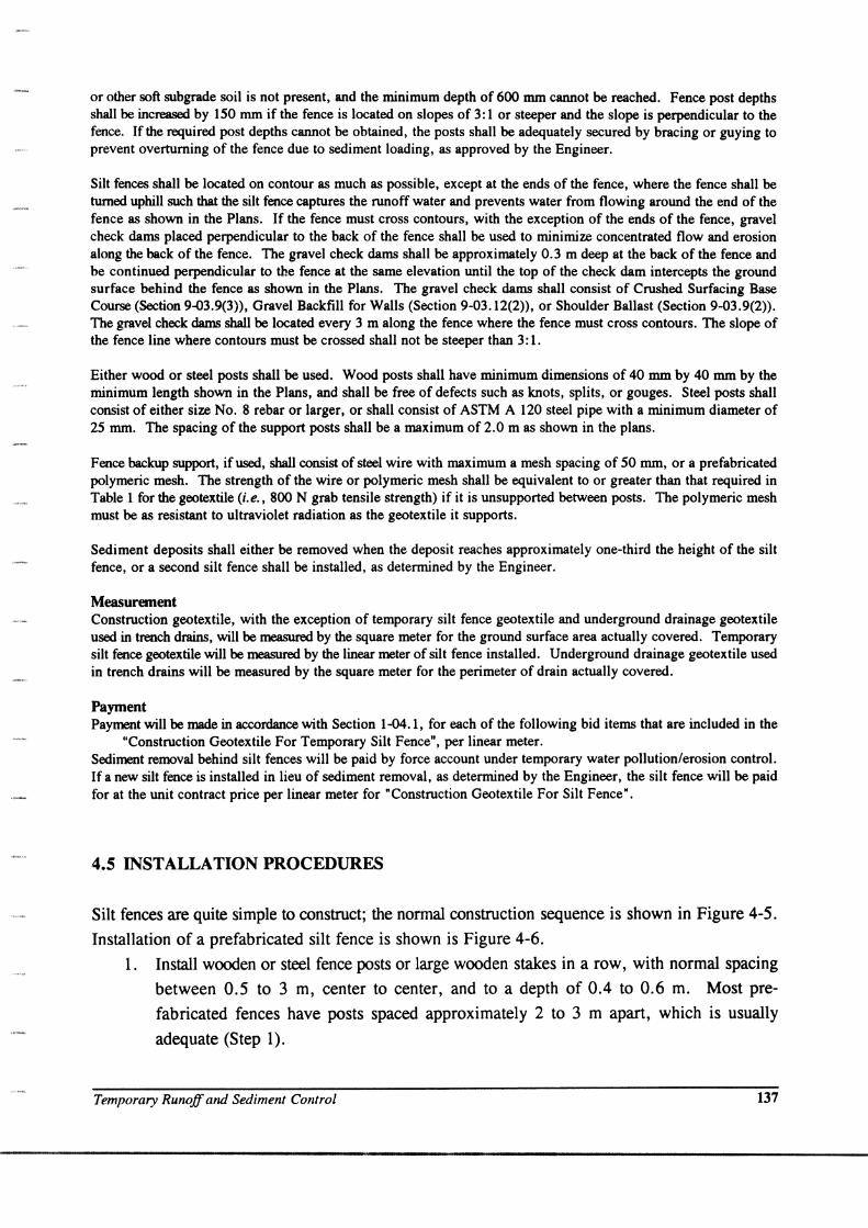
or other soft subgrade soil is not present, and the minimum depth of 600 nun cannot be reached. Fence post depths shall be increased by 150 nun if the fence is located on slopes of 3: 1 or steeper and the slope is perpendicular to the fence. If the required post depths cannot be obtained, the posts shall be adequately secured by bracing or guying to prevent overturning of the fence due to sediment loading, as approved by the Engineer.
Silt fences shall be located on contour as much as possible, except at the ends of the fence, where the fence shall be turned uphill such that the silt fence captures the runoff water and prevents water from flowing around the end of the fence as shown in the Plans. If the fence must cross contours, with the exception of the ends of the fence, gravel check dams placed perpendicular to the back of the fence shall be used to minimize concentrated flow and erosion along the back of the fence. The gravel check dams shall be approximately 0.3 m deep at the back of the fence and be continued perpendicular to the fence at the same elevation until the top of the check dam intercepts the ground surface behind the fence as shown in the Plans. The gravel check dams shall consist of Crushed Surfacing Base Course (Section 9-03.9(3», Gravel Backfill for Walls (Section 9-03.12(2», or Shoulder Ballast (Section 9-03.9(2». The gravel check dams shall be located every 3 m along the fence where the fence must cross contours. The slope of the fence line where contours must be crossed shall not be steeper than 3: 1.
Either wood or steel posts shall be used. Wood posts shall have minimum dimensions of 40 nun by 40 nun by the minimum length shown in the Plans, and shall be free of defects such as knots, splits, or gouges. Steel posts shall consist of either size No.8 rebar or larger, or shall consist of ASTM A 120 steel pipe with a minimum diameter of 25 nun. The spacing of the support posts shall be a maximum of 2.0 m as shown in the plans.
Fence backup support, ifused, shall consist of steel wire with maximum a mesh spacing of 50 nun, or a prefabricated polymeric mesh. The strength of the wire or polymeric mesh shall be equivalent to or greater than that required in Table 1 for the geotextile (i.e., 800 N grab tensile strength) if it is unsupported between posts. The polymeric mesh must be as resistant to ultraviolet radiation as the geotextile it supports.
Sediment deposits shall either be removed when the deposit reaches approximately one-third the height of the silt fence, or a second silt fence shall be installed, as determined by the Engineer.
Measurement Construction geotextile, with the exception of temporary silt fence geotextile and underground drainage geotextile used in trench drains, will be measured by the square meter for the ground surface area actually covered. Temporary silt fence geotextile will be measured by the linear meter of silt fence installed. Underground drainage geotextile used in trench drains will be measured by the square meter for the perimeter of drain actually covered.
Payment Payment will be made in accordance with Section 1-04.1, for each of the following bid items that are included in the
"Construction Geotextile For Temporary Silt Fence", per linear meter. Sediment removal behind silt fences will be paid by force account under temporary water pollution/erosion control. If a new silt fence is installed in lieu of sediment removal, as determined by the Engineer, the silt fence will be paid for at the unit contract price per linear meter for "Construction Geotextile For Silt Fence".
4.5 INSTALLATION PROCEDURES
Silt fences are quite simple to construct; the normal construction sequence is shown in Figure 4-5.
Installation of a prefabricated silt fence is shown is Figure 4-6.
1. Install wooden or steel fence posts or large wooden stakes in a row, with normal spacing
between 0.5 to 3 m, center to center, and to a depth of 0.4 to 0.6 m. Most pre
fabricated fences have posts spaced approximately 2 to 3 m apart, which is usually
adequate (Step 1).
Temporary Runoff and Sediment Control 137
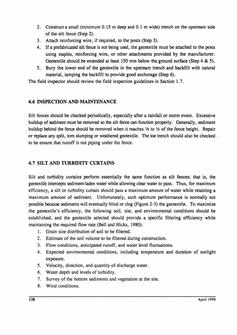
2. Construct a small (minimum 0.15 m deep and 0.1 m wide) trench on the upstream side
of the silt fence (Step 2).
3. Attach reinforcing wire, if required, to the posts (Step 3).
4. If a prefabricated silt fence is not being used, the geotextile must be attached to the posts
using staples, reinforcing wire, or other attachments provided by the manufacturer.
Geotextile should be extended at least 150 mm below the ground surface (Step 4 & 5).
5. Bury the lower end of the geotextile in the upstream trench and backfill with natural
material, tamping the backfill to provide good anchorage (Step 6).
The field inspector should review the field inspection guidelines in Section 1.7.
4.6 INSPECTION AND MAINTENANCE
Silt fences should be checked periodically, especially after a rainfall or storm event. Excessive
buildup of sediment must be removed so the silt fence can function properly. Generally, sediment
buildup behind the fence should be removed when it reaches 113 to V2 of the fence height. Repair
or replace any split, tom slumping or weathered geotextile. The toe trench should also be checked .
to be ensure that runoff is not piping under the fence.
4.7 SILT AND TURBIDITY CURTAINS
Silt and turbidity curtains perform essentially the same function as silt fences; that is, the
geotextile intercepts sediment-laden water while allowing clear water to pass. Thus, for maximum
efficiency, a silt or turbidity curtain should pass a maximum amount of water while retaining a
maximum amount of sediment. Unfortunately, such optimum performance is normally not
possible because sediments will eventually blind or clog (Figure 2-3) the geotextile. To maximize
the geotextile's efficiency, the following soil, site, and environmental conditions should be
established, and the geotextile selected should provide a specific filtering efficiency while
maintaining the required flow rate (Bell and Hicks, 1980).
138
1. Grain size distribution of soil to be filtered.
2.
3. 4.
5. 6. 7.
8.
Estimate of the soil volume to be filtered during construction.
Flow conditions, anticipated runoff, and water level fluctuations.
Expected environmental conditions, including temperature and duration of sunlight
exposure.
Velocity, direction, and quantity of discharge water.
Water depth and levels of turbidity.
Survey of the bottom sediments and vegetation at the site.
Wind conditions.
April 1998
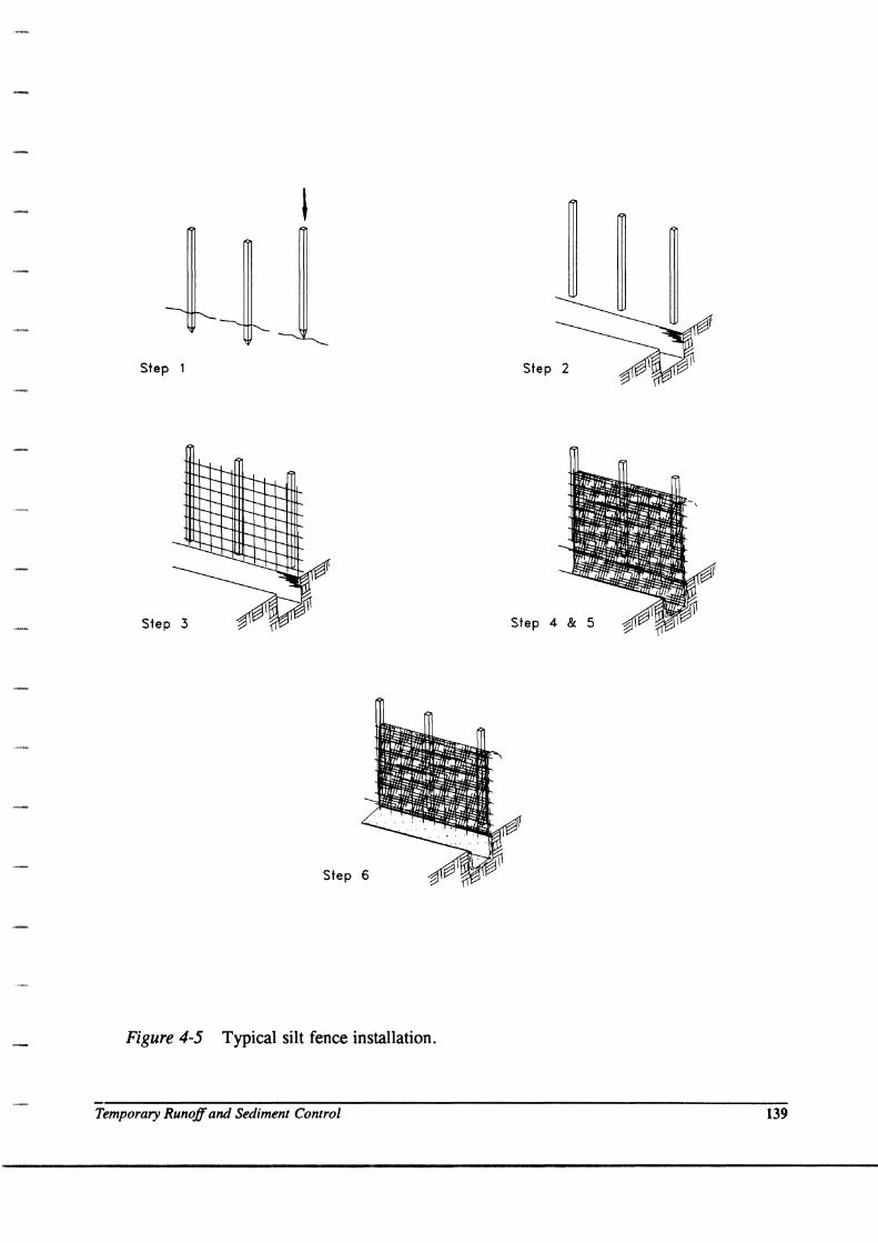
Step 1 Step 2
Step 3 Step 4 & 5
Step 6
Figure 4-5 Typical silt fence installation.
Temporary Runoff and Sediment Control 139
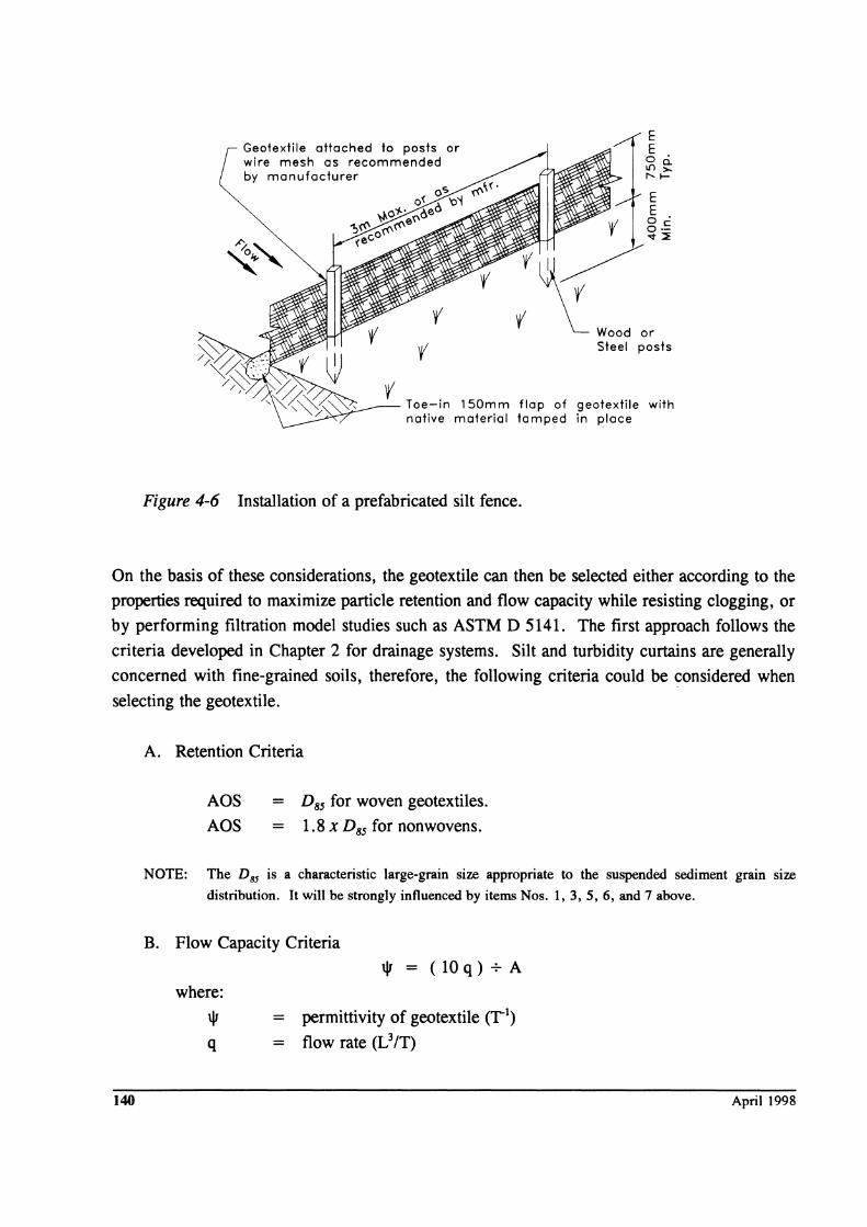
Geotextile atta ched to posts or wire mesh as recommended by manufacturer
E E o· Lf)~ r"-I-
E E o·
\1/ o.!:: r """ ~
:~o, Steel posts
Toe-in 150mm flap of geotextile with native material tamped in place
Figure 4-6 Installation of a prefabricated silt fence.
On the basis of these considerations, the geotextile can then be selected either according to the
properties required to maximize particle retention and flow capacity while resisting clogging, or
by performing filtration model studies such as ASTM D 5141. The first approach follows the
criteria developed in Chapter 2 for drainage systems. Silt and turbidity curtains are generally
concerned with fine-grained soils, therefore, the following criteria could be considered when
selecting the geotextile.
140
A. Retention Criteria
AOS = D85 for woven geotextiles.
AOS = 1.8 X D85 for nonwovens.
NOTE: The DS5 is a characteristic large-grain size appropriate to the suspended sediment grain size
distribution. It will be strongly influenced by items Nos. 1,3,5,6, and 7 above.
B. Flow Capacity Criteria
where:
\j1
q
\j1=(lOq)+A
= permittivity of geotextile (1, .. 1)
= flow rate (L3/T)
April 1998
A = cross-sectional area silt curtain (L2)
10 = factor of safety
C. Clogging Resistance
Maximize ADS requirements using largest opening possible from criterion A above.
For silt and turbidity curtain construction, the geotextile forming the curtain is held vertical by
flotation segments at the top and a ballast along the bottom (Bell and Hicks, 1980). A tension
cable is often built into the curtain immediately above or below the flotation segments to absorb
stress imposed by currents, wave action, and wind. Barrier sections are usually about 30 m long
and of any required width. Curtains can also be constructed within shallow bodies of water using
silt fence-type construction methods. Geotextiles have also been attached to soldier piles and
draped across riprap barriers as semipermanent curtains.
The U.S. Army Corps of Engineers (1977) indicates that silt and turbidity curtains are not
appropriate for certain conditions, such as:
• operations in open ocean;
• operations in currents exceeding 0.5 m/s;
• in areas frequently exposed to high winds and large breaking waves; and
• near hopper or cutter head dredges where frequent curtain movement would be
necessary.
4.8 EROSION CONTROL BLANKETS
In freshly graded areas, the soil is susceptible to erosion by rainfall and runoff. Temporary,
degradable blankets are used to enhance the establishment of vegetation. These products are used
where vegetation alone provides sufficient site protection after the temporary products degrade.
Such products are usually evaluated by field trial sections, and, therefore, are empirically
designed. There are very few published records of comparative use, so the user must decide on
the preferable system, usually based on local experience. You should be aware that a variety of
products and systems exist. As an aid to selecting the best system, consult manufacturers and
other agencies about their experiences.
Erosion protection must be provided for three distinct phases, namely:
1. prior to vegetation growth;
2. during vegetation growth; and
3. after vegetation is fully established.
Temporary Runoff and Sediment Control 141
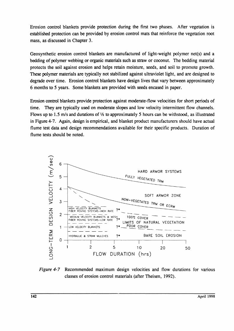
Erosion control blankets provide protection during the first two phases. After vegetation is
established protection can be provided by erosion control mats that reinforce the vegetation root
mass, as discussed in Chapter 3.
Geosynthetic erosion control blankets are manufactured of light-weight polymer net(s) and a
bedding of polymer webbing or organic materials such as straw or coconut. The bedding material
protects the soil against erosion and helps retain moisture, seeds, and soil to promote growth.
These polymer materials are typically not stabilized against ultraviolet light, and are designed to
degrade over time. Erosion control blankets have design lives that vary between approximately
6 months to 5 years. Some blankets are provided with seeds encased in paper.
Erosion control blankets provide protection against moderate-flow velocities for short periods of
time. They are typically used on moderate slopes and low velocity intermittent flow channels.
Flows up to 1.5 mls and durations of 1/2 to approximately 5 hours can be withstood, as illustrated
in Figure 4-7. Again, design is empirical, and blanket product manufacturers should have actual
flume test data and design recommendations available for their specific products. Duration of
flume tests should be noted.
142
'--" 5 >I--
U o -1 W > Z C)
(f) w o
:::E 0:::
4
3
2
HARD ARMOR SYSTEMS
TRM
SOFT ARMOR ZONE
NON-VEGETATED TRM OR ECRM
HIGH VELOCITY BLANKETS FIBER ROVING SYSTEMS-HIGH RATE ? ------
MEDIUM VELOCITY BLANKETS & MESH 100% COVER - --FIBER ROVING SYSTEMS-LOW RATE 7*
LIMITS OF NATURAL VEGETATION LOW VELOCITY BLANKETS 7. -"OOR COVER
------HYDRAULIC &: STRAW MULCHES ?* BARE SOIL EROSION
W I--I
C)
o -+-------~I------~--------~------~------~
z o -1
2 5 10
FLOW DURATION (hrs) 20 50
Figure 4-7 Recommended maximum design velocities and flow durations for various
classes of erosion control materials (after Theisen, 1992).
April 1998
Since the design of erosion control blankets is empirical, specification by index properties is not
easily accomplished. Also, relatively few test methods have been standardized for erosion control
blankets. Therefore, it is recommended that specifications use an approved products list.
Construction plans and specifications should detail and note installation requirements. Details
such as anchoring in trenches, use of pins, pin length, pin spacing, roll overlap requirements, and
roll termination should be addressed.
The following example specification for erosion control blankets is after the Texas Department
of Transportation specification for RECP (rolled erosion control products). This agency tests
candidate erosion control materials and categorizes them into classes and types in an approved
materials list.
SOIL EROSION CONTROL BLANKETS (after Texas Department of Transportation, Special Specification, Item 1225, February 1993)
1. DESCRIPTION.
This item shall govern for providing and placing wood, straw, or coconut fiber mat, synthetic mat, jute mesh
or other material as a soil erosion control blankets on slopes or ditches or for short-term or long-term protection
of seeded areas as shown on the plans or as specified by the Engineer.
2. MATERIALS.
(1) Soil Erosion Control Blankets. All soil erosion control blankets must be prequalified by the Director of
Maintenance and Operations prior to use.
Prequalification procedures and a current list of prequalified materials may be obtained by writing to the
Director of Maintenance and Operations. A 0.3 m x 0.3 m sample of the material may be required by the
Engineer in order to verify prequa1ification. Samples taken, accompanied by the manufacturer's literature,
will be sent, properly wrapped and identified, to the Division of Maintenance and Operations for
verification.
The soil erosion control blanket shall be one (I) of the following classes and types as shown on the plans:
(a) Class 1. "SIQpe Protection"
(i) Type A. Slopes of 3: 1 or flatter - Clay soils
Prequalified Type A products are:
Temporary Runoff and Sediment Control 143
(ii) Type B. Slopes of 3: 1 or flatter - Sandy soils
Prequalified Type B products are:
(iii) Type C. Slopes steeper than 3: 1 - Clay soils
Prequalified Type C products are:
(iv) Type D. Slopes steeper than 3: 1 - Sandy soils
Prequalified Type D products are:
(b) Class 2. "Flexible Channel Liner"
(i) Type E. Short-term duration (Up to 2 Years)
Shear Stress (td) < 50 Pa
Prequalified Type E products are:
(ii) Type F. Short-term duration (Up to 2 Years)
Shear Stress (tJ 50 to 95 Pa
Prequalified Type F products are:
(2) ~. Staples for anchoring the soil erosion control mat shall be U-shaped, made of 3 mm or large
diameter steel wire, or other approved material, have a width of 25 to 50 mm, and a length of not less than
150 mm for firm soils and not less than 300 mm for loose soils.
3. CONSTRUCTION METHODS.
144
(1) General. The soil erosion control blanket shall conform to the class and type shown on the plans. The
Contractor has the option of selecting an approved soil erosion control blanket conforming to the class and
type shown on the plans, and according to the current approved material list.
April 1998
(2) Installation. The soil erosion control blanket, whether installed as slope protection or as flexible channel
liner in accordance with the approved materials list, shall be placed within 24 hours after seeding or
sodding operations have been completed, or as approved by the Engineer. Prior to placing the blanket,
the area to be covered shall be relatively free of all rocks or clods over 38 mm in maximum dimension and
all sticks or other foreign material which will prevent the close contact of the blanket with the soil. The
area shall be smooth and free of ruts or depressions exist for any reason, the Contractor shall be required
to rework the soil until it is smooth and to reseed or resod the area at the Contractor's expense.
Installation and anchorage of the soil erosion control mat shall be in accordance with the project
construction drawings unless otherwise specified in the contract or directed by the Engineer.
(3) Literature. The Contractor shall submit one (1) full set of manufacturer's literature and manufacturer's
installation recommendations for the soil erosion control blanket selected in accordance with the approved
material list.
4. MEASUREMENT.
This Item will be measured by the square meter of surface area covered.
s. PAYMENT.
The work performed and materials furnished in accordance with this Item and measured as provided under
"Measurement" will be paid for at the unit price bid for "Soil Erosion Control Blanket" of the class and type
shown on the plans. This price shall be full compensation for furnishing all materials, labor, tools, equipment
and incidentals necessary to complete the work. Anchors, checks, terminals or junction slots, and wire staples
or wood stakes will not be paid for directly but will be considered subsidiary to this Item.
4.9 REFERENCES
AASHTO, SttuuiIlrd SpedjicoJions Jor Geotextiks - M 288, Standard Specifications for TlllWIportation Materials and MetJJock of SamPIinK and Teitina, IS111 Edition, American Association of State Transportation and Highway Officials, Washington, D.C., 1997.
Allen, personal communication, 1994.
ASTM (1997), Soil and Rock (//): D 4943 - latest,· Geosynthetics, Annual Book of ASIM Standards, Section 4, Volume 04.09, American Society for Testing and Materials, West Conshohocken, PA, 1246 p.
ASIM Test Methods - see Appendix E.
Bell, J.R. and Hicks, R.G, Eyaluation of Test Methods and Use Criteria for Geotechnical Fabrics in HiKhwaY APJllications - Interim Report, Report No. FHWAIRD-80/021, Federal Highway Administration, Washington, D.C., June 1980, 190 p.
HydroDynamics Incorporated, Identifyina and Controllina ErosioQ and SedimentatioQ, FHW A Project No. DTnI61-C-97-OOO13, U.S. Department of Transportation, Federal Highway Administration, Washington, D.C., Nov 1997, DRAFT, 264 p.
Temporary Runoff and Sediment Control 145
Mallard, P. and Bell, J.R., Use of Fabrics in Erosion Control, Transportation Research &;port 81-4, Federal Highway Administration, Washington, D.C., January, 1981.
Renard, K.G., Foster, G.R., Weesies, G.A., McCool, D.K., and Yoder, D.C., Predicting SoU Erosion by Water: A GuNk to ConseTWJtion Planning with the Revised Universal Soil Loss EqUlJlion (RUSLE), USDA Agricultural Handbook No, 703, U.S. Department or Agriculture, Washington, D.C., 1997,384 p.
Richardson, G.N. and Middlebrooks, P., A Simplified Design Method for Silt Fences, ProceediDlS or the Geosyntbetjgi '91 Conference, Industrial Fabrics Association International, St. Paul, MN, 1991, pp. 879-888.
Richardson, G.N. and Koerner, R.M., Editors, A DesilW Primer: Geotextiles and Related Materials, Industrial Fabrics Association International, St. Paul, MN, 1990, 166 p.
Soil Conservation Service, National EO&ineeriO& Handbook, Sections 11 and 14, U.S. Department of Agriculture, Washington, D.C., 1977.
Theisen, M.S., Geosynihetics in Erosion Control and Sediment Control, Geotecbnjcal Fabrics Report, Industrial Fabrics Association International, St. Paul, MN, May/June 1992, pp. 26-35.
U.S. Army Corps of Engineers , Civil Workr Construction Guide Specificationfor Plastic Filter Fabric, Corps of Engineer Specifications No. CW-02215, Office, Chief of Engineers, U.S. Army Corps of Engineers, Washington, D.C., 1977.
Wyant, D.C., Evaluation of Filter Fabricsfor Use as Silt Fences, Report No. VHTRC 80-R49, Virginia Highway and Transportation Research Council, Charlottesville, VA, 1980.
146 April 1998