geotec gv – series high efficiency geothermal/water · pdf file ·...
TRANSCRIPT

Form No. S3546-518Supersedes S3546-318 Page 1 of 16
TYPICAL INSTALLATIONUnit installs upright and hooks up conveniently to supply water system. Ideal for closet, basement, or utility room installation. Requires very little floor space. Can be installed with or without return air duct.
Steel Cabinet:Galvanized 20 gauge zinc coated steel cabinet with baked-on, textured enamel which allows it to withstand 1000 hours of salt spray exposure.
Multi-Capacity Two-Stage:Simple thermostatic control seamlessly stages the compressor and indoor airflow rate between full and part load capacity operation without cycling the compressor. This helps to maximize comfort, humidity control, energy efficiency and overall reduction in compressor cycling for improved system life.
Step Capacity Compressor:Copeland step-capacity (2-stage) scroll compressors are designed for increased efficiency, quieter operation and improved reliability for longer life.
R-410A Refrigerant:Designed with R-410A (HFC) non-ozone depleting refrigerant in compliance with the Montreal protocol and 2010 EPA requirements.
Liquid Line Drier:Protects system against moisture.
Lockout Circuit:Built-in lockout circuit resets from the room thermostat. Provides commercial quality protection to the compressor.
High Pressure Switch:Provides additional protection for the system.
Control Panel:Mid-level for easy access can be reversed to other side for installation flexibility.
Fluid Flow Switches:Provided for both source and load coils to assure proper flow for safe operation.
The Bard GEOTEC® Geothermal/Water Source Packaged Heat Pump delivers economical year-round comfort by utilizing nature’s most abundant and efficient solar energy collector – the earth. The GV Series heat pumps are designed for low water flow rates and offer cooling efficiencies up to 30.2 EER and heating efficiencies up to 5.1 COP on ground water, and cooling efficiencies up to 26.2 EER and heating efficiencies up to 3.9 COP on ground loop.
All units are shipped prewired for fast, easy installation in residential or commercial buildings. They are available in five popular, vertical, self-contained models. Left hand or right hand option in same cabinet. Unit shipped as right hand and can be field converted to left hand.
Ground Water Application: Water Temp 45° to 75°
Ground Loop Application: Temp Range 25° to 110°
Engineered FeaturesLow Pressure Switch:Two switches provided. Factory wired switch is for ground water applications, alternate switch is field connected for ground loop applications.
High Efficiency Coaxial Water Coil in either Copper or Cupronickel:Water to refrigerant coil is completely insulated to prevent frost build-up at low temperature operation. NOTE: Copper water coils are not warranted for ground water/open loop installations.
Indoor Air Coil:Grooved copper tubing and enhanced louvered aluminum fin for maximum heat transfer and energy efficiency.Coil coating is black E-Coat electrostatic coating on complete coil.
Service Access Ports:Permits service pressure check of discharge and suction pressures.
Filter Rack:Factory installed with 2" MERV 6 pleated filter (reversible for left or right side access).
Thermostatic Expansion Valve:For wide range refrigerant control (2-way operation).
Optional Accessories:Room thermostat - Water accessory kit - Waterflow controls.
Isolated Compressor Base:The compressor is mounted to an isolated mounting plate for sound and vibration reduction.
Domestic Hot Water Heat Exchanger:Double wall vented heat exchanger, factory installed on all models - optional GVDM26 pump kit required for hot water heating.
Water Connections:All water connections on outside of cabinet with dual side connections. Brass full swivel double o-ring connection with 1" full flow ports.
Electric Heat:Slide in Electric Heater Package - up to 18KW can be field installed with circuit breakers as standard (reversible for left or right side access).
Variable Speed ECM Blower Motor:• High Efficiency• Soft starting - low noise on start up• Continuous fan - will operate at 50% of rated Stage 2 airflow
Mild Weather Operation:Part Load Cooling Operation will operate at 20% reduced airflow for the first 5 minutes of operation. This results in 32% increased applied moisture removal during this 5-minute period, and helps humidity control during short-run conditions. This is seamlessly controlled internal of the unit controls with no required user intervention.
Condensate Drain Connection:Centered side-to-side under indoor coil with integral trap and 4-installer selectable outlet connection points. Installer connection is 3/4" PVC Glue Fitting. Outlet is elevated for allowing condensate pump installation.
Service Ports:On the cabinet exterior for easy access.
Geothermal Logic Control:With diagnostic lights for ease of troubleshooting.
Discharge Muffler:Installed to reduce compressor pulsations to improve sound level and quality.
GV Model Shown with Optional GVDM-26Desuperheater Pump Module (Field Installed)
GEOTEC® GV – Series High Efficiency Geothermal/Water Source Packaged Step-Capacity Heat Pump — R-410A
External Service Ports

Form No. S3546-518Supersedes S3546-318Page 2 of 16
+75°C copper wire ++ HACR type circuit breaker* C - for copper / N for Cupro-Nickel water coil Heat pump only. Optional field-installed heaters are separate circuit.
Specifications
Copper water coils are not warranted for ground water/open loop installations.
MODEL GV27S3AA* GV38S3AA* GV51S3AA* GV61S3AA* GV71S3AA*
Electrical Rating (Volts/Hertz/Phase) 230/208-1
Operating Voltage Range 253-197 VAC
Minimum Circuit Ampacity 19 24 32 40 44
+Field Wire Size #12 #10 #8 #6 #6
+ Ground Wire Size 12 10 10 10 8
++Delay Fuse of Circuit Breaker Max. 30 40 50 60 70
COMPRESSOR
Volts 230/208
Rated Load Amps (230/208) 7.5/8.6 12.0/13.65 15.8/17.6 21.9/24.2 26.3/28.9
Branch Circuit Selection Current 11.7 15.3 21.2 27.2 29.7
Locked Rotor Amps (230/208) 58.3/58.3 83.0/83.0 104.0/104.0 152.9/152.9 179.2/179.2
BLOWER MOTOR AND EVAPORATOR
Blower Motor - HP/Speed/Type 1/3 / 5 / ECM 1/2 / 5 / ECM 1/2 / 5 / ECM 3/4 / 5 / ECM 3/4 / 5 / ECM
Blower Motor - Amps 1.5 / 1.6 2.5 / 2.95 2.8 / 3.0 3.8 / 4.1 4.1 / 4.2
Face Area Sq. Ft./Row/Fins Per Inch 3.16 / 4 / 11 3.16 / 4 / 11 5.33 / 3 / 11 5.33 / 4 / 11 5.33 / 5 / 10
AIR FILTERS
2" Pleated MERV 6 20 x 25 x 2 (1) 20 x 25 x 2 (1) 16 x 25 x 2 (2) 16 x 25 x 2 (2) 16 x 25 x 2 (2)
SHIPPING WEIGHT LBS.
Shipping Weight 340 345 390 440 450
G V 38 S 3 A A C
Electrical CharacteristicsA = 230/208-60-1
Modification CodeApproximate
Capacity Size on Full Load
S = Step Capacity Compressor
V = Vertical
GeothermalHeat Pump C = Copper Water Coil
(for Closed Loop Applications Only)
N = Cupronickel Water Coil(for Open or Closed Loop Applications)
GEOTEC® GV-Series Geothermal / Water Source Heat Pump Nomenclature
• Intertek ETL Listed to Standard for Safety Heating and Cooling Equipment ANSI/UL 1995/CSA 22.2 No. 236-05, Fourth Edition.
A = Black E-Coated Air Coil
Bard is anISO 9001:2008
Certified Manufacturer

Form No. S3546-518Supersedes S3546-318 Page 3 of 16
ISO Standard 13256-1:1998, “Water to Air and Brine to Air Heat Pumps”, which includes watt allowance for water pumping. Cooling capacity based on 80.6°F DB, 66.2°F WB entering air temperature. Heating capacity based on 68°F DB entering air temperature.
ISO 13256-1 Performance Data
All Models are Energy Star Tier 3 Qualified for Ground Loop and Ground Water Applications.
MODELSYSTEM
CAPACITY MODULATION
FLUID FLOW
RATE GPM
AIRFLOW CFM
GROUND LOOP HEAT PUMPTested & Certified to ISO 13256-1:1998
Cooling BrineFull Load 77°FPart Load 68°F
Heating BrineFull Load 32°FPart Load 41°F
CAPACITYBTUH
EERBTU/W
Energy Star Rating
CAPACITYBTUH COP Energy Star
Rating
GV27 Full LoadPart Load
7.007.00
1000800
26,60020,800
18.1026.00
22.0520,20017,100
4.104.60
4.35
GV38 Full LoadPart Load
9.009.00
1300900
38,50028,600
17.1024.90
21.0031,40024,200
4.054.45
4.25
GV51 Full LoadPart Load
12.0012.00
15001150
49,50038,600
17.1023.80
20.4539,50032,000
3.754.15
3.95
GV61 Full LoadPart Load
15.0015.00
16001300
60,50046,500
16.5021.50
19.0049,00039,000
3.603.90
3.75
GV71 Full LoadPart Load
16.0016.00
17501450
69,50056,500
15.3019.80
17.5557,00048,450
3.654.00
3.83
MODELSYSTEM
CAPACITY MODULATION
FLUID FLOW
RATE GPM
AIRFLOW CFM
GROUND WATER HEAT PUMPTested & Certified to ISO 13256-1:1998
Cooling – 59°F EWT Heating – 50°F EWT
CAPACITYBTUH
EERBTU/W
Energy Star Rating
CAPACITYBTUH COP Energy Star
Rating
GV27 Full LoadPart Load
7.007.00
1000800
26,60022,200
24.5030.20
27.3526,20019,800
5.205.35
5.28
GV38 Full LoadPart Load
9.009.00
1300900
41,40030,200
22.0029.50
25.7538,60027,600
4.704.95
4.83
GV51 Full LoadPart Load
12.0012.00
15001150
53,50040,500
21.7029.10
25.4049,50036,000
4.454.60
4.53
GV61 Full LoadPart Load
15.0015.00
16001300
65,50049,500
20.5025.80
23.1562,50045,500
4.104.30
4.20
GV71 Full LoadPart Load
16.0016.00
17501450
75,50059,000
19.9023.50
21.7073,50056,000
4.204.40
4.30

Form No. S3546-518Supersedes S3546-318Page 4 of 16
GV27S3
EnteringFluidTemp. (°F)
EnteringAir Temp.
(°F)
Total Capacity(MBtuH)
SensibleCapacity(MBtuH)
Sensibleto TotalRatio
PowerInput(KW)
Heat ofRejection(MBtuH)
EER
50°
70° DB59° WB
29.5 22.9 0.77 1.05 33.1 24.260° 27.9 22.2 0.79 1.21 32.0 21.770° 26.3 21.5 0.82 1.37 30.8 19.280° 24.8 20.8 0.84 1.54 29.6 16.790° 23.2 20.0 0.87 1.70 28.5 14.2
100° 21.7 19.3 0.89 1.86 27.3 11.7110° 20.1 18.6 0.92 2.02 26.1 9.250°
75° DB63° WB
31.6 23.8 0.74 1.07 35.6 25.660° 30.0 23.1 0.76 1.23 34.3 23.070° 28.3 22.4 0.79 1.39 33.1 20.480° 26.7 21.7 0.81 1.55 31.9 17.790° 25.0 20.9 0.84 1.71 30.7 15.1
100° 23.4 20.2 0.86 1.87 29.4 12.5110° 21.7 19.5 0.89 2.03 28.2 9.850°
80° DB67° WB
33.9 24.7 0.71 1.09 38.1 27.160° 32.2 23.9 0.74 1.25 36.9 24.470° 30.4 23.2 0.76 1.41 35.6 21.680° 28.7 22.5 0.79 1.57 34.3 18.890° 26.9 21.8 0.81 1.73 33.0 16.1
100° 25.2 21.1 0.84 1.89 31.7 13.3110° 23.4 20.4 0.86 2.05 30.4 10.550°
85° DB71° WB
36.3 25.5 0.69 1.11 40.8 28.660° 34.5 24.7 0.71 1.27 39.5 25.770° 32.6 24.0 0.74 1.43 38.1 22.880° 30.7 23.3 0.76 1.59 36.8 19.990° 28.9 22.6 0.79 1.75 35.4 17.0
100° 27.0 21.9 0.81 1.91 34.0 14.1110° 25.1 21.2 0.84 2.07 32.7 11.3
EnteringFluidTemp. (°F)
EnteringAir Temp.
(°F)
Total Capacity(MBtuH)
Leaving Air
Temp. (°F)
PowerInput(KW)
Heat ofAbsorption(MBtuH)
COP
25°
65°
19.3 82.9 1.41 14.9 4.1
30° 21.1 84.5 1.44 16.6 4.3
40° 24.5 87.7 1.51 19.9 4.7
50° 28.0 90.9 1.58 23.2 5.2
60° 32.0 94.6 1.69 26.9 5.5
70° 36.0 98.3 1.79 30.5 5.9
80° 39.9 102.0 1.90 34.2 6.2
25°
70°
18.9 87.5 1.45 14.5 3.9
30° 20.6 89.1 1.48 16.1 4.1
40° 24.0 92.2 1.55 19.3 4.6
50° 27.4 95.4 1.62 22.6 5.0
60° 31.3 99.0 1.73 26.1 5.3
70° 35.2 102.6 1.84 29.7 5.6
80° 39.0 106.2 1.95 33.2 5.9
25°
75°
19.1 92.7 1.62 14.0 3.5
30° 20.8 94.3 1.66 15.6 3.7
40° 24.3 97.5 1.74 18.7 4.1
50° 27.7 100.6 1.82 21.9 4.5
60° 31.6 104.3 1.94 25.3 4.8
70° 35.5 107.9 2.07 28.8 5.0
80° 39.5 111.6 2.19 32.2 5.3
EnteringFluidTemp. (°F)
EnteringAir Temp.
(°F)
Total Capacity(MBtuH)
SensibleCapacity(MBtuH)
Sensibleto TotalRatio
PowerInput(KW)
Heat ofRejection(MBtuH)
EER
50°
70° DB59° WB
22.3 17.9 0.79 0.52 24.3 32.060° 21.1 17.4 0.82 0.67 23.5 28.270° 19.9 16.8 0.85 0.82 22.7 24.380° 18.7 16.3 0.88 0.97 21.8 20.590° 17.4 15.7 0.90 1.12 21.0 16.7
100° 16.2 15.2 0.93 1.27 20.2 12.8110° 15.0 14.6 0.96 1.42 19.4 9.050°
75° DB63° WB
23.9 18.6 0.76 0.53 26.1 34.060° 22.6 18.0 0.79 0.68 25.2 29.970° 21.4 17.5 0.82 0.83 24.4 25.980° 20.1 17.0 0.85 0.98 23.5 21.890° 18.8 16.4 0.88 1.13 22.6 17.8
100° 17.5 15.9 0.91 1.28 21.8 13.7110° 16.2 15.3 0.94 1.43 20.9 9.650°
80° DB67° WB
25.7 19.2 0.73 0.54 28.0 35.960° 24.3 18.7 0.76 0.69 27.1 31.770° 22.9 18.2 0.79 0.84 26.2 27.480° 21.6 17.6 0.82 0.99 25.3 23.190° 20.2 17.1 0.85 1.14 24.4 18.9
100° 18.9 16.6 0.88 1.29 23.5 14.6110° 17.5 16.0 0.91 1.44 22.5 10.350°
85° DB71° WB
27.5 19.9 0.71 0.55 29.9 37.960° 26.0 19.3 0.74 0.70 29.0 33.470° 24.6 18.8 0.76 0.85 28.0 28.980° 23.1 18.3 0.79 1.00 27.1 24.590° 21.7 17.7 0.82 1.15 26.1 20.0
100° 20.2 17.2 0.85 1.30 25.2 15.5110° 18.8 16.7 0.88 1.45 24.2 11.1
EnteringFluidTemp. (°F)
EnteringAir Temp.
(°F)
Total Capacity(MBtuH)
Leaving Air
Temp. (°F)
PowerInput(KW)
Heat ofAbsorption(MBtuH)
COP
25°
65°
14.5 81.8 1.07 11.2 4.0
30° 16.0 83.5 1.08 12.6 4.3
40° 18.8 86.7 1.10 15.5 5.0
50° 21.6 90.0 1.12 18.4 5.7
60° 24.2 93.0 1.14 20.9 6.2
70° 26.8 96.0 1.17 23.5 6.7
80° 29.4 99.0 1.19 26.0 7.3
25°
70°
14.2 86.5 1.10 10.9 3.8
30° 15.6 88.1 1.11 12.3 4.1
40° 18.4 91.3 1.13 15.1 4.8
50° 21.1 94.4 1.15 17.9 5.4
60° 23.7 97.4 1.18 20.3 5.9
70° 26.2 100.3 1.20 22.8 6.4
80° 28.8 103.3 1.23 25.3 6.9
25°
75°
14.4 91.6 1.24 10.6 3.4
30° 15.8 93.3 1.25 11.9 3.7
40° 18.6 96.5 1.27 14.6 4.3
50° 21.4 99.7 1.29 17.3 4.8
60° 23.9 102.7 1.32 19.7 5.3
70° 26.5 105.7 1.35 22.1 5.8
80° 29.1 108.6 1.38 24.5 6.2
COOLING FULL LOAD HEATING FULL LOAD
Full Load Capacities based upon rated flow of 7 GPM at 1000 CFM airflow.
Part Load Capacities based upon rated flow of 7 GPM at 800 CFM airflow.COOLING PART LOAD HEATING PART LOAD

Form No. S3546-518Supersedes S3546-318 Page 5 of 16
GV38S3
COOLING FULL LOAD HEATING FULL LOAD
Full Load Capacities based upon rated flow of 9 GPM at 1300 CFM airflow.
Part Load Capacities based upon rated flow of 9 GPM at 900 CFM airflow.COOLING PART LOAD HEATING PART LOAD
EnteringFluidTemp. (°F)
EnteringAir Temp.
(°F)
Total Capacity(MBtuH)
SensibleCapacity(MBtuH)
Sensibleto TotalRatio
PowerInput(KW)
Heat ofRejection(MBtuH)
EER
50°
70° DB59° WB
38.3 29.0 0.75 1.59 43.5 21.160° 36.6 28.3 0.77 1.83 42.5 19.070° 35.0 27.6 0.79 2.07 41.5 16.980° 33.3 27.0 0.81 2.30 40.6 14.990° 31.6 26.3 0.84 2.54 39.6 12.8
100° 29.9 25.6 0.86 2.78 38.7 10.8110° 28.2 25.0 0.88 3.02 37.7 8.750°
75° DB63° WB
41.2 30.1 0.72 1.62 46.7 22.360° 39.4 29.4 0.74 1.85 45.7 20.270° 37.6 28.8 0.77 2.09 44.7 18.080° 35.8 28.1 0.79 2.33 43.7 15.890° 34.0 27.5 0.81 2.57 42.7 13.7
100° 32.2 26.8 0.83 2.80 41.7 11.5110° 30.4 26.2 0.85 3.04 40.7 9.350°
80° DB67° WB
44.2 31.2 0.70 1.65 50.0 23.660° 42.3 30.5 0.72 1.88 49.0 21.470° 40.4 29.9 0.74 2.12 48.0 19.180° 38.5 29.2 0.76 2.36 47.0 16.890° 36.6 28.6 0.78 2.59 45.9 14.5
100° 34.7 28.0 0.81 2.83 44.9 12.3110° 32.8 27.3 0.83 3.07 43.9 10.050°
85° DB71° WB
47.3 32.2 0.67 1.68 53.6 24.960° 45.3 31.5 0.69 1.91 52.5 22.570° 43.3 30.9 0.71 2.15 51.4 20.180° 41.3 30.3 0.74 2.39 50.4 17.890° 39.2 29.7 0.76 2.62 49.3 15.4
100° 37.2 29.0 0.78 2.86 48.2 13.0110° 35.2 28.4 0.80 3.09 47.1 10.7
EnteringFluidTemp. (°F)
EnteringAir Temp.
(°F)
Total Capacity(MBtuH)
Leaving Air
Temp. (°F)
PowerInput(KW)
Heat ofAbsorption(MBtuH)
COP
25°
65°
26.1 83.6 2.06 19.7 3.7
30° 28.5 85.3 2.11 21.9 4.0
40° 33.1 88.6 2.21 26.3 4.4
50° 37.8 91.9 2.31 30.7 4.8
60° 42.6 95.3 2.45 35.0 5.1
70° 47.3 98.7 2.60 39.4 5.3
80° 52.1 102.1 2.75 43.8 5.6
25°
70°
25.5 88.2 2.11 19.1 3.5
30° 27.8 89.8 2.17 21.2 3.7
40° 32.4 93.1 2.27 25.5 4.2
50° 37.0 96.3 2.37 29.8 4.6
60° 41.6 99.6 2.52 34.0 4.8
70° 46.3 102.9 2.67 38.3 5.1
80° 50.9 106.3 2.82 42.5 5.3
25°
75°
25.8 93.4 2.37 18.5 3.2
30° 28.1 95.0 2.43 20.6 3.4
40° 32.8 98.3 2.55 24.7 3.8
50° 37.4 101.6 2.66 28.9 4.1
60° 42.1 105.0 2.83 33.0 4.3
70° 46.8 108.3 3.00 37.1 4.6
80° 51.5 111.7 3.17 41.2 4.8
EnteringFluidTemp. (°F)
EnteringAir Temp.
(°F)
Total Capacity(MBtuH)
SensibleCapacity(MBtuH)
Sensibleto TotalRatio
PowerInput(KW)
Heat ofRejection(MBtuH)
EER
50°
70° DB59° WB
27.8 21.1 0.75 0.71 30.4 29.460° 26.4 20.5 0.77 0.91 29.6 26.070° 25.1 20.0 0.80 1.11 28.8 22.580° 23.7 19.4 0.82 1.31 28.0 19.190° 22.4 18.8 0.84 1.52 27.2 15.7
100° 21.0 18.3 0.87 1.72 26.4 12.2110° 19.7 17.7 0.89 1.92 25.6 8.850°
75° DB63° WB
29.9 21.9 0.72 0.72 32.6 31.260° 28.4 21.4 0.75 0.92 31.8 27.570° 27.0 20.8 0.77 1.12 30.9 23.980° 25.6 20.2 0.79 1.33 30.1 20.390° 24.1 19.7 0.82 1.53 29.3 16.7
100° 22.7 19.1 0.84 1.73 28.4 13.1110° 21.3 18.6 0.87 1.94 27.6 9.550°
80° DB67° WB
32.0 22.7 0.70 0.73 35.0 33.060° 30.5 22.1 0.72 0.94 34.1 29.270° 29.0 21.6 0.74 1.14 33.2 25.480° 27.5 21.0 0.77 1.34 32.3 21.690° 25.9 20.5 0.79 1.55 31.5 17.7
100° 24.4 19.9 0.82 1.75 30.6 13.9110° 22.9 19.4 0.84 1.95 29.7 10.150°
85° DB71° WB
34.3 23.4 0.67 0.75 37.4 34.860° 32.7 22.9 0.70 0.95 36.5 30.870° 31.1 22.3 0.72 1.16 35.6 26.880° 29.4 21.8 0.74 1.36 34.7 22.890° 27.8 21.3 0.77 1.56 33.8 18.8
100° 26.2 20.7 0.79 1.77 32.9 14.8110° 24.6 20.2 0.81 1.97 31.9 10.8
EnteringFluidTemp. (°F)
EnteringAir Temp.
(°F)
Total Capacity(MBtuH)
Leaving Air
Temp. (°F)
PowerInput(KW)
Heat ofAbsorption(MBtuH)
COP
25°
65°
18.2 83.7 1.49 13.7 3.6
30° 19.9 85.5 1.50 15.5 3.9
40° 23.5 89.1 1.53 19.0 4.5
50° 27.0 92.8 1.56 22.5 5.1
60° 30.1 96.0 1.59 25.5 5.5
70° 33.2 99.2 1.62 28.5 6.0
80° 36.3 102.3 1.65 31.5 6.5
25°
70°
17.8 88.3 1.53 13.3 3.4
30° 19.5 90.0 1.54 15.1 3.7
40° 22.9 93.6 1.57 18.5 4.3
50° 26.4 97.1 1.60 21.9 4.8
60° 29.4 100.3 1.63 24.8 5.3
70° 32.5 103.4 1.66 27.7 5.7
80° 35.5 106.5 1.69 30.5 6.1
25°
75°
18.0 93.5 1.72 12.9 3.1
30° 19.7 95.3 1.73 14.6 3.3
40° 23.2 98.9 1.77 17.9 3.8
50° 26.7 102.4 1.80 21.2 4.3
60° 29.7 105.6 1.83 24.0 4.8
70° 32.8 108.8 1.86 26.8 5.2
80° 35.9 111.9 1.90 29.6 5.6

Form No. S3546-518Supersedes S3546-318Page 6 of 16
GV51S3
COOLING FULL LOAD HEATING FULL LOAD
Full Load Capacities based upon rated flow of 12 GPM at 1500 CFM airflow.
Part Load Capacities based upon rated flow of 12 GPM at 1150 CFM airflow.COOLING PART LOAD HEATING PART LOAD
EnteringFluidTemp. (°F)
EnteringAir Temp.
(°F)
Total Capacity(MBtuH)
SensibleCapacity(MBtuH)
Sensibleto TotalRatio
PowerInput(KW)
Heat ofRejection(MBtuH)
EER
50°
70° DB59° WB
50.9 37.7 0.74 2.14 58.2 28.060° 48.8 36.7 0.75 2.44 56.8 24.670° 46.7 35.7 0.76 2.75 55.4 21.280° 44.6 34.6 0.78 3.05 54.0 17.890° 42.5 33.6 0.79 3.36 52.6 14.4
100° 40.4 32.6 0.81 3.66 51.1 11.0110° 38.3 31.5 0.82 3.97 49.7 7.650°
75° DB63° WB
54.6 39.2 0.71 2.17 62.5 29.760° 52.4 38.1 0.73 2.48 61.0 26.170° 50.2 37.1 0.74 2.78 59.6 22.580° 48.0 36.1 0.75 3.09 58.1 18.990° 45.7 35.1 0.77 3.39 56.6 15.4
100° 43.5 34.1 0.78 3.70 55.2 11.8110° 41.3 33.0 0.80 4.00 53.7 8.250°
80° DB67° WB
58.6 40.5 0.69 2.21 67.0 31.460° 56.2 39.5 0.70 2.52 65.5 27.770° 53.9 38.5 0.71 2.82 64.0 23.980° 51.5 37.5 0.73 3.12 62.4 20.190° 49.2 36.5 0.74 3.43 60.9 16.3
100° 46.8 35.5 0.76 3.73 59.4 12.6110° 44.5 34.5 0.77 4.03 57.8 8.850°
85° DB71° WB
62.7 41.8 0.66 2.26 71.8 33.160° 60.2 40.9 0.68 2.56 70.2 29.270° 57.8 39.9 0.69 2.86 68.6 25.280° 55.3 38.9 0.70 3.16 66.9 21.390° 52.8 37.9 0.72 3.47 65.3 17.3
100° 50.3 36.9 0.73 3.77 63.7 13.3110° 47.8 35.9 0.75 4.07 62.1 9.4
EnteringFluidTemp. (°F)
EnteringAir Temp.
(°F)
Total Capacity(MBtuH)
Leaving Air
Temp. (°F)
PowerInput(KW)
Heat ofAbsorption(MBtuH)
COP
25°
65°
35.1 86.7 2.87 26.4 3.6
30° 38.0 88.5 2.93 29.0 3.8
40° 43.7 92.0 3.06 34.3 4.2
50° 49.5 95.5 3.19 39.5 4.5
60° 55.9 99.5 3.41 45.3 4.8
70° 62.4 103.5 3.62 51.0 5.0
80° 68.9 107.5 3.84 56.8 5.3
25°
70°
34.3 91.2 2.95 25.6 3.4
30° 37.2 92.9 3.01 28.2 3.6
40° 42.8 96.4 3.15 33.3 4.0
50° 48.4 99.9 3.28 38.3 4.3
60° 54.7 103.8 3.5 43.9 4.6
70° 61.0 107.7 3.72 49.6 4.8
80° 67.3 111.6 3.94 55.2 5.1
25°
75°
34.7 96.4 3.31 24.9 3.1
30° 37.6 98.2 3.38 27.3 3.3
40° 43.2 101.7 3.53 32.3 3.6
50° 48.9 105.2 3.68 37.2 3.9
60° 55.3 109.1 3.93 42.6 4.1
70° 61.7 113.1 4.18 48.1 4.3
80° 68.1 117.0 4.42 53.5 4.5
EnteringFluidTemp. (°F)
EnteringAir Temp.
(°F)
Total Capacity(MBtuH)
SensibleCapacity(MBtuH)
Sensibleto TotalRatio
PowerInput(KW)
Heat ofRejection(MBtuH)
EER
50°
70° DB59° WB
37.6 28.1 0.74 1.17 41.6 26.060° 35.9 27.4 0.76 1.43 40.6 23.270° 34.3 26.7 0.78 1.69 39.6 20.480° 32.6 26.0 0.80 1.95 38.5 17.590° 30.9 25.3 0.82 2.21 37.5 14.7
100° 29.3 24.6 0.84 2.47 36.5 11.9110° 27.6 23.9 0.86 2.73 35.5 9.150°
75° DB63° WB
40.4 29.2 0.71 1.19 44.7 27.660° 38.6 28.5 0.73 1.45 43.6 24.670° 36.9 27.8 0.75 1.71 42.5 21.680° 35.1 27.1 0.77 1.97 41.5 18.790° 33.3 26.4 0.79 2.23 40.4 15.7
100° 31.5 25.7 0.81 2.49 39.3 12.7110° 29.8 25.0 0.84 2.75 38.3 9.750°
80° DB67° WB
43.3 30.2 0.69 1.21 47.9 29.260° 41.5 29.5 0.71 1.47 46.8 26.170° 39.6 28.9 0.73 1.73 45.7 22.980° 37.7 28.2 0.75 1.99 44.6 19.890° 35.8 27.5 0.77 2.25 43.5 16.7
100° 34.0 26.8 0.79 2.51 42.3 13.5110° 32.1 26.1 0.81 2.77 41.2 10.450°
85° DB71° WB
46.4 31.2 0.66 1.23 51.3 30.860° 44.4 30.5 0.68 1.49 50.1 27.570° 42.4 29.9 0.70 1.75 49.0 24.280° 40.4 29.2 0.72 2.02 47.8 20.990° 38.4 28.5 0.74 2.28 46.6 17.7
100° 36.5 27.9 0.76 2.54 45.5 14.4110° 34.5 27.2 0.78 2.80 44.3 11.1
EnteringFluidTemp. (°F)
EnteringAir Temp.
(°F)
Total Capacity(MBtuH)
Leaving Air
Temp. (°F)
PowerInput(KW)
Heat ofAbsorption(MBtuH)
COP
25°
65°
24.7 84.9 2.10 18.2 3.5
30° 26.9 86.7 2.13 20.4 3.7
40° 31.4 90.3 2.18 24.8 4.2
50° 35.9 93.9 2.23 29.1 4.7
60° 40.6 97.7 2.31 33.7 5.1
70° 45.3 101.5 2.39 38.2 5.6
80° 50.0 105.3 2.46 42.8 6.0
25°
70°
24.1 89.4 2.16 17.7 3.3
30° 26.3 91.2 2.18 19.8 3.5
40° 30.7 94.7 2.24 24.0 4.0
50° 35.1 98.2 2.29 28.3 4.4
60° 39.7 101.9 2.37 32.7 4.9
70° 44.3 105.7 2.45 37.1 5.3
80° 48.9 109.4 2.53 41.5 5.7
25°
75°
24.4 94.6 2.42 17.1 3.0
30° 26.6 96.4 2.45 19.2 3.2
40° 31.0 100.0 2.51 23.3 3.6
50° 35.4 103.5 2.58 27.4 4.0
60° 40.1 107.3 2.66 31.7 4.4
70° 44.8 111.1 2.75 36.0 4.8
80° 49.4 114.8 2.84 40.3 5.1

Form No. S3546-518Supersedes S3546-318 Page 7 of 16
GV61S3
COOLING FULL LOAD HEATING FULL LOAD
Full Load Capacities based upon rated flow of 15 GPM at 1600 CFM airflow.
Part Load Capacities based upon rated flow of 15 GPM at 1300 CFM airflow.COOLING PART LOAD HEATING PART LOAD
EnteringFluidTemp. (°F)
EnteringAir Temp.
(°F)
Total Capacity(MBtuH)
SensibleCapacity(MBtuH)
Sensibleto TotalRatio
PowerInput(KW)
Heat ofRejection(MBtuH)
EER
50°
70° DB59° WB
63.4 44.3 0.69 2.67 71.9 20.860° 60.5 42.9 0.71 3.06 70.0 18.770° 57.6 41.5 0.72 3.44 68.2 16.780° 54.7 40.1 0.73 3.83 66.3 14.790° 51.8 38.7 0.75 4.22 64.4 12.6
100° 48.9 37.2 0.76 4.61 62.5 10.6110° 46.0 35.8 0.78 4.99 60.7 8.650°
75° DB63° WB
68.1 46.0 0.67 2.71 77.2 22.060° 65.0 44.6 0.68 3.10 75.3 19.970° 61.9 43.2 0.70 3.49 73.3 17.880° 58.9 41.8 0.71 3.87 71.4 15.690° 55.8 40.4 0.73 4.26 69.4 13.5
100° 52.7 39.0 0.74 4.65 67.4 11.4110° 49.7 37.6 0.75 5.03 65.5 9.250°
80° DB67° WB
73.0 47.6 0.65 2.76 82.8 23.360° 69.7 46.2 0.66 3.15 80.8 21.170° 66.5 44.8 0.67 3.53 78.7 18.880° 63.2 43.4 0.69 3.92 76.7 16.690° 60.0 42.0 0.70 4.30 74.6 14.3
100° 56.7 40.6 0.72 4.68 72.6 12.1110° 53.5 39.2 0.73 5.07 70.5 9.950°
85° DB71° WB
78.1 49.2 0.62 2.82 88.7 24.560° 74.7 47.8 0.64 3.20 86.5 22.270° 71.3 46.4 0.65 3.58 84.4 19.980° 67.8 45.0 0.66 3.97 82.2 17.590° 64.4 43.6 0.68 4.35 80.1 15.2
100° 60.9 42.2 0.69 4.74 77.9 12.9110° 57.5 40.8 0.71 5.12 75.8 10.5
EnteringFluidTemp. (°F)
EnteringAir Temp.
(°F)
Total Capacity(MBtuH)
Leaving Air
Temp. (°F)
PowerInput(KW)
Heat ofAbsorption(MBtuH)
COP
25°
65°
44.4 90.7 3.62 33.0 3.6
30° 48.0 92.8 3.73 36.3 3.8
40° 55.2 97.0 3.96 43.0 4.1
50° 62.5 101.1 4.19 49.6 4.4
60° 70.0 105.5 4.48 56.1 4.6
70° 77.5 109.9 4.78 62.6 4.8
80° 85.0 114.2 5.07 69.1 4.9
25°
70°
43.4 95.1 3.71 32.0 3.5
30° 47.0 97.2 3.83 35.3 3.6
40° 54.0 101.3 4.06 41.7 3.9
50° 61.0 105.3 4.30 48.2 4.2
60° 68.4 109.6 4.60 54.5 4.3
70° 75.8 113.8 4.90 60.7 4.5
80° 83.1 118.1 5.21 67.0 4.7
25°
75°
43.9 100.4 4.17 31.1 3.1
30° 47.5 102.5 4.30 34.2 3.2
40° 54.6 106.6 4.56 40.5 3.5
50° 61.7 110.7 4.83 46.7 3.7
60° 69.2 115.0 5.17 52.8 3.9
70° 76.6 119.3 5.51 58.9 4.1
80° 84.0 123.6 5.85 65.0 4.2
EnteringFluidTemp. (°F)
EnteringAir Temp.
(°F)
Total Capacity(MBtuH)
SensibleCapacity(MBtuH)
Sensibleto TotalRatio
PowerInput(KW)
Heat ofRejection(MBtuH)
EER
50°
70° DB59° WB
46.8 33.6 0.71 1.46 51.3 25.360° 44.5 32.5 0.73 1.80 50.0 22.570° 42.2 31.5 0.75 2.15 48.7 19.780° 39.9 30.5 0.76 2.49 47.4 16.890° 37.6 29.4 0.78 2.83 46.1 14.0
100° 35.4 28.4 0.80 3.17 44.8 11.2110° 33.1 27.3 0.82 3.51 43.5 8.350°
75° DB63° WB
50.2 34.9 0.69 1.49 55.1 26.860° 47.8 33.8 0.70 1.83 53.7 23.970° 45.4 32.8 0.72 2.17 52.4 20.980° 43.0 31.8 0.74 2.51 51.0 17.990° 40.5 30.7 0.76 2.86 49.6 14.9
100° 38.1 29.7 0.78 3.20 48.3 11.9110° 35.7 28.6 0.80 3.54 46.9 8.950°
80° DB67° WB
53.9 36.1 0.66 1.52 59.1 28.460° 51.3 35.1 0.68 1.86 57.6 25.370° 48.7 34.0 0.70 2.20 56.2 22.180° 46.2 33.0 0.72 2.54 54.8 19.090° 43.6 32.0 0.74 2.89 53.4 15.9
100° 41.0 30.9 0.75 3.22 52.0 12.7110° 38.5 29.9 0.77 3.57 50.5 9.650°
85° DB71° WB
57.7 37.3 0.64 1.55 63.2 29.960° 55.0 36.3 0.66 1.89 61.7 26.770° 52.2 35.2 0.67 2.23 60.2 23.480° 49.5 34.2 0.69 2.58 58.8 20.190° 46.8 33.2 0.71 2.92 57.3 16.8
100° 44.1 32.1 0.73 3.26 55.8 13.5110° 41.3 31.1 0.75 3.60 54.3 10.2
EnteringFluidTemp. (°F)
EnteringAir Temp.
(°F)
Total Capacity(MBtuH)
Leaving Air
Temp. (°F)
PowerInput(KW)
Heat ofAbsorption(MBtuH)
COP
25°
65°
32.5 88.1 2.77 24.0 3.4
30° 35.1 90.0 2.80 26.6 3.7
40° 40.4 93.8 2.87 31.8 4.1
50° 45.7 97.5 2.93 36.9 4.6
60° 50.8 101.2 3.01 41.8 4.9
70° 56.0 104.9 3.10 46.7 5.3
80° 61.1 108.5 3.19 51.6 5.6
25°
70°
31.7 92.6 2.85 23.3 3.3
30° 34.3 94.4 2.88 25.8 3.5
40° 39.5 98.1 2.94 30.8 3.9
50° 44.6 101.8 3.01 35.8 4.4
60° 49.7 105.4 3.10 40.6 4.7
70° 54.7 109.0 3.19 45.3 5.0
80° 59.7 112.5 3.28 50.1 5.4
25°
75°
32.1 97.9 3.20 22.6 3.0
30° 34.7 99.7 3.23 25.1 3.1
40° 39.9 103.4 3.30 29.9 3.5
50° 45.1 107.1 3.37 34.7 3.9
60° 50.2 110.8 3.48 39.3 4.2
70° 55.3 114.4 3.58 44.0 4.5
80° 60.4 118.0 3.68 48.6 4.8

Form No. S3546-518Supersedes S3546-318Page 8 of 16
GV71S3
COOLING FULL LOAD HEATING FULL LOAD
Full Load Capacities based upon rated flow of 16 GPM at 1750 CFM airflow.
Part Load Capacities based upon rated flow of 16 GPM at 1450 CFM airflow.COOLING PART LOAD HEATING PART LOAD
EnteringFluidTemp. (°F)
EnteringAir Temp.
(°F)
Total Capacity(MBtuH)
SensibleCapacity(MBtuH)
Sensibleto TotalRatio
PowerInput(KW)
Heat ofRejection(MBtuH)
EER
50°
70° DB59° WB
68.7 49.0 0.71 3.27 76.2 18.860° 65.3 47.2 0.72 3.68 74.4 17.070° 62.0 45.4 0.73 4.09 72.5 15.280° 58.6 43.6 0.75 4.50 70.7 13.490° 55.2 41.8 0.76 4.91 68.8 11.5
100° 51.8 40.0 0.77 5.32 67.0 9.7110° 48.4 38.2 0.78 5.73 65.1 7.950°
75° DB63° WB
73.8 50.9 0.68 3.32 81.9 19.960° 70.2 49.1 0.70 3.73 79.9 18.070° 66.6 47.3 0.71 4.14 78.0 16.180° 63.1 45.5 0.72 4.55 76.1 14.290° 59.5 43.6 0.74 4.96 74.1 12.3
100° 55.9 41.8 0.75 5.36 72.2 10.4110° 52.3 40.0 0.76 5.77 70.3 8.550°
80° DB67° WB
79.2 52.7 0.66 3.38 87.8 21.060° 75.4 50.9 0.67 3.79 85.8 19.070° 71.6 49.1 0.69 4.19 83.7 17.180° 67.8 47.2 0.70 4.60 81.7 15.190° 63.9 45.4 0.71 5.01 79.7 13.1
100° 60.1 43.6 0.72 5.41 77.7 11.1110° 56.3 41.8 0.74 5.82 75.7 9.150°
85° DB71° WB
84.8 54.4 0.64 3.45 94.0 22.260° 80.7 52.6 0.65 3.85 91.9 20.170° 76.7 50.8 0.66 4.25 89.8 18.080° 72.7 49.0 0.68 4.66 87.7 15.990° 68.6 47.1 0.69 5.06 85.6 13.9
100° 64.6 45.3 0.70 5.47 83.5 11.8110° 60.5 43.5 0.71 5.87 81.3 9.7
EnteringFluidTemp. (°F)
EnteringAir Temp.
(°F)
Total Capacity(MBtuH)
Leaving Air
Temp. (°F)
PowerInput(KW)
Heat ofAbsorption(MBtuH)
COP
25°
65°
50.4 91.7 4.10 37.7 3.6
30° 54.3 93.7 4.21 41.2 3.8
40° 62.0 97.8 4.44 48.1 4.1
50° 69.8 101.9 4.66 55.0 4.4
60° 79.0 106.8 4.96 63.2 4.6
70° 88.2 111.7 5.26 71.5 4.9
80° 97.4 116.5 5.56 79.8 5.2
25°
70°
49.3 96.1 4.21 36.6 3.4
30° 53.1 98.1 4.33 40.0 3.6
40° 60.7 102.1 4.56 46.7 3.9
50° 68.2 106.1 4.79 53.4 4.2
60° 77.2 110.8 5.09 61.4 4.4
70° 86.2 115.6 5.40 69.4 4.7
80° 95.2 120.4 5.71 77.5 4.9
25°
75°
49.8 101.4 4.73 35.5 3.1
30° 53.7 103.4 4.86 38.8 3.2
40° 61.3 107.4 5.12 45.3 3.5
50° 69.0 111.5 5.37 51.8 3.8
60° 78.1 116.3 5.72 59.6 4.0
70° 87.1 121.1 6.07 67.4 4.2
80° 96.2 125.9 6.41 75.2 4.4
EnteringFluidTemp. (°F)
EnteringAir Temp.
(°F)
Total Capacity(MBtuH)
SensibleCapacity(MBtuH)
Sensibleto TotalRatio
PowerInput(KW)
Heat ofRejection(MBtuH)
EER
50°
70° DB59° WB
53.9 38.5 0.70 1.95 59.4 22.860° 51.4 37.4 0.72 2.34 57.9 20.470° 48.8 36.2 0.74 2.72 56.4 18.080° 46.3 35.1 0.76 3.10 54.9 15.590° 43.7 34.0 0.78 3.48 53.4 13.1
100° 41.1 32.9 0.80 3.87 51.8 10.6110° 38.6 31.8 0.82 4.25 50.3 8.250°
75° DB63° WB
57.9 39.9 0.68 1.99 63.8 24.260° 55.2 38.8 0.70 2.37 62.2 21.670° 52.5 37.7 0.72 2.75 60.7 19.180° 49.8 36.6 0.74 3.14 59.1 16.590° 47.1 35.5 0.76 3.52 57.5 13.9
100° 44.4 34.4 0.78 3.90 55.9 11.4110° 41.7 33.3 0.79 4.28 54.3 8.850°
80° DB67° WB
62.1 41.3 0.66 2.03 68.4 25.660° 59.3 40.2 0.68 2.41 66.8 22.970° 56.4 39.2 0.69 2.79 65.1 20.280° 53.5 38.1 0.71 3.17 63.5 17.590° 50.6 37.0 0.73 3.55 61.8 14.8
100° 47.8 35.9 0.75 3.94 60.2 12.1110° 44.9 34.8 0.77 4.32 58.5 9.450°
85° DB71° WB
66.5 42.7 0.63 2.07 73.3 27.060° 63.5 41.6 0.65 2.45 71.5 24.270° 60.4 40.5 0.67 2.83 69.8 21.380° 57.4 39.5 0.69 3.21 68.1 18.590° 54.3 38.4 0.71 3.59 66.3 15.7
100° 51.3 37.3 0.73 3.98 64.6 12.9110° 48.2 36.2 0.75 4.36 62.9 10.1
EnteringFluidTemp. (°F)
EnteringAir Temp.
(°F)
Total Capacity(MBtuH)
Leaving Air
Temp. (°F)
PowerInput(KW)
Heat ofAbsorption(MBtuH)
COP
25°
65°
38.5 89.6 3.19 28.5 3.5
30° 41.8 91.7 3.25 31.6 3.8
40° 48.3 95.8 3.35 37.8 4.2
50° 54.8 100.0 3.45 44.0 4.7
60° 61.5 104.3 3.58 50.4 5.0
70° 68.2 108.5 3.72 56.8 5.4
80° 74.9 112.8 3.86 63.1 5.7
25°
70°
37.6 94.0 3.28 27.7 3.4
30° 40.8 96.1 3.33 30.7 3.6
40° 47.2 100.2 3.44 36.7 4.0
50° 53.6 104.2 3.54 42.7 4.4
60° 60.1 108.4 3.68 48.9 4.8
70° 66.7 112.6 3.82 55.1 5.1
80° 73.2 116.7 3.96 61.3 5.5
25°
75°
38.1 99.3 3.68 26.8 3.0
30° 41.3 101.4 3.74 29.8 3.2
40° 47.7 105.5 3.86 35.6 3.6
50° 54.2 109.6 3.98 41.4 4.0
60° 60.8 113.8 4.13 47.4 4.3
70° 67.4 118.0 4.29 53.5 4.6
80° 74.0 122.3 4.45 59.5 4.9

Form No. S3546-518Supersedes S3546-318 Page 9 of 16
Motor will automatically step through the various airflows with thermostatic control ESP = External Static Pressure (inches of water) Maximum allowable duct static Continuous airflow is the CFM being circulated with manual fan operation without any additional function occurring. Will occur automatically for first 5 minutes of Part Load Cooling Operation. Will occur automatically after five minutes of Part Load Cooling Operation. This is a field option for noisy installations to de-rate Full Load airflow (requires change in control panel). Will occur automatically with control signal input (will not be defeated for electric heat operation).
Indoor Blower Performance (CFM)
Airflow Corrections
Correction Factors @ Increased Water Flows
MODEL MOTORHP
RATED
ESP
MAXESP
Speed #1 Speed #2 Speed #3 Speed #4 Speed #5
Continuous
Airflow
Mild Weather
Operation in 1st Stage Cooling Mode (5-Min.)
Part Load Operation
Airflow
-10% Full
Load Airflow (Optional)
Full Load Airflow
and Electric Heat Mode
GV27S3 1/3 0.15 0.50 500 650 800 900 1000
GV38S3 1/2 0.15 0.50 650 725 900 1175 1300
GV51S3 1/2 0.20 0.50 750 925 1150 1350 1500
GV61S3 3/4 0.20 0.50 800 1050 1300 1450 1600
GV71S3 3/4 0.25 0.50 875 1150 1450 1575 1750
% of Rated Airflow
Total Capacity (MBtuH)
Sensible Capacity (MBtuH)
Power Input(KW)
Heat of Rejection (MBtuH)
Total Capacity (MBtuH)
Power Input(KW)
Heat of Absorption (MBtuH)
88% 0.982 0.782 0.973 0.979 0.985 1.037 0.973
90% 0.985 0.844 0.978 0.983 0.988 1.030 0.978
92% 0.989 0.905 0.982 0.987 0.990 1.023 0.983
94% 0.992 0.967 0.987 0.991 0.993 1.016 0.988
96% 0.995 0.978 0.991 0.994 0.995 1.011 0.992
98% 0.997 0.989 0.996 0.997 0.998 1.005 0.996
RATED 1.000 1.000 1.000 1.000 1.000 1.000 1.000
102% 1.002 1.011 1.005 1.003 1.002 0.997 1.004
104% 1.005 1.023 1.011 1.006 1.005 0.993 1.007
106% 1.007 1.034 1.016 1.009 1.007 0.99 1.011
108% 1.009 1.042 1.020 1.011 1.009 0.989 1.013
110% 1.010 1.050 1.025 1.013 1.010 0.988 1.015
112% 1.012 1.057 1.029 1.015 1.012 0.986 1.017
Rated FlowPlus
Cooling Heating
BtuH Watts BtuH Watts
2 GPM 1.005 0.988 1.006 1.002
3 GPM 1.007 0.984 1.009 1.003
4 GPM 1.008 0.979 1.011 1.003

Form No. S3546-518Supersedes S3546-318Page 10 of 16
Pump output (feet of head) @ GPM at top of column.
Water Coil Pressure Drop (Fresh Water)
Minimum Required Flow Rates for Ground Water Installations
Loop Pump Modules and Pump Outputs for Ground Loop Installations
Required Flow Rates for Ground Loop Installations
Loop antifreeze protection must be determined based on loop design and geographic location. Must not be denatured with any petroleum based product.
See Antifreeze table below.
Antifreeze Percentages by Volume for Ground Loop Installations
MODEL GV27S3 GV38S3 / GV51S3 GV61S3 GV71S3
GPM PSID Ft. Hd. PSID Ft. Hd. PSID Ft. Hd. PSID Ft. Hd.
3 0.1 0.23
4 0.5 1.15 0.9 2.08
5 1.2 2.77 1.4 3.23
6 1.7 3.92 2.3 5.31
7 2.3 5.31 3.2 7.38 2 4.61
8 3.1 7.15 4.1 9.46 2.5 5.77 2 4.61
9 4.1 9.46 5.1 11.77 3.2 7.38 2.4 5.54
10 6.1 14.07 3.9 9.00 2.8 6.46
11 7.1 16.38 4.7 10.84 3.4 7.84
12 8.2 18.92 5.5 12.69 3.9 9.00
13 9.4 21.69 6.4 14.76 4.5 10.38
14 10.6 24.45 7.3 16.84 5.2 12.00
15 8.1 18.69 5.9 13.61
16 9 20.76 6.7 15.46
17 9.9 22.84 7.4 17.07
18 8.4 19.38
Pump Models No. of PumpsWATER FLOW RATE REQUIRED IN GPM
7 9 12 15 16
DORFC-1 1 28.5 27.5 25 22.5 22
DORFC-2 2 57 55 50 45 44
GV27S3 GV38S3 GV51S3 GV61S3 GV71S3
Flow rate required GPM fresh water (Rated) 5 (7) 6 (9) 7 (12) 9 (15) 10 (16)
GV27S3 GV38S3 GV51S3 GV61S3 GV71S3
Flow rate required GPM Propylene Glycol, Methanol or Ethanol
7 9 12 15 16
TypeMinimum Temperature for Freeze Protection
10°F (-12.2°C) 15°F (-9.4°C) 20°F (-6.7°C) 25°F (-3.9°C)
Methanol 25% 21% 16% 10%
Ethanol 29% 25% 20% 14%
100% USP Food Grade Propylene Glycol 27% 24% 20% 13%
Form No. S3546-518Supersedes S3546-318 Page 11 of 16
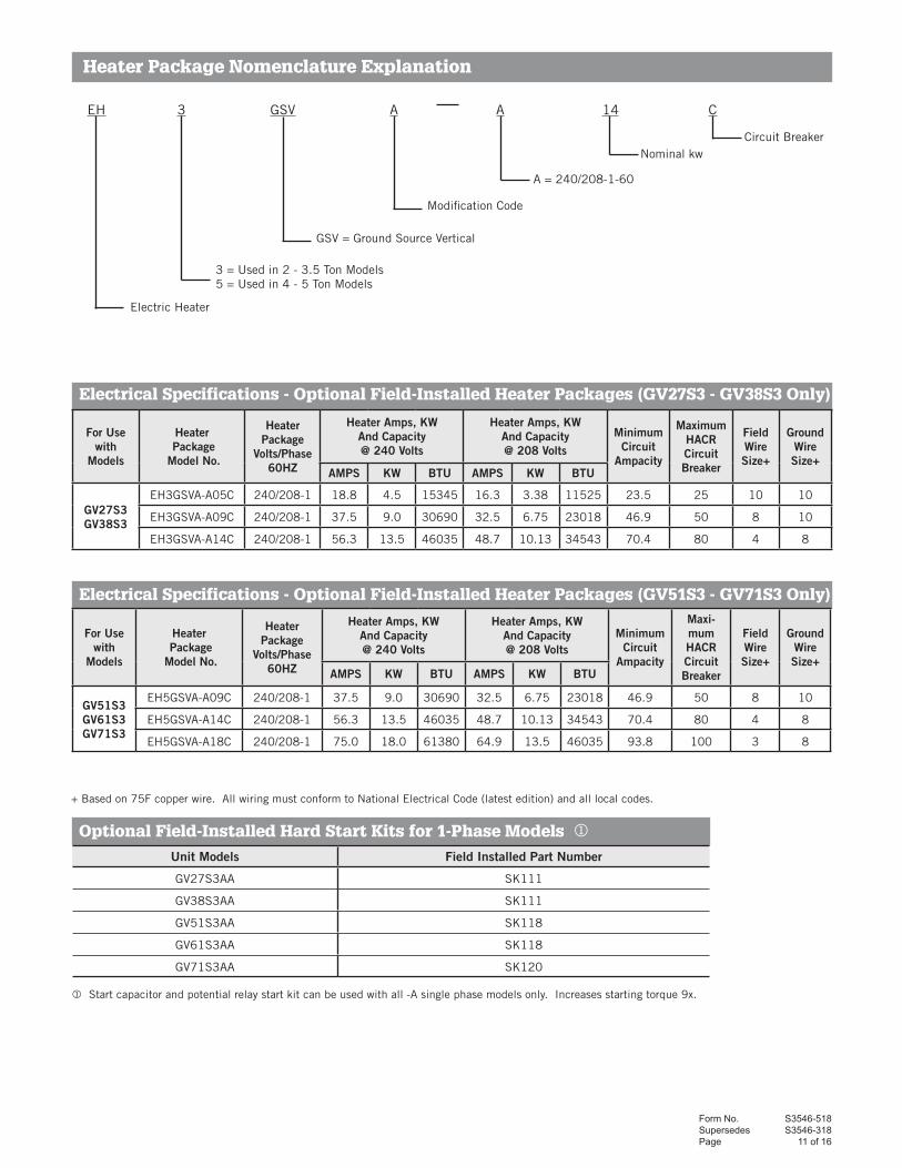
EH 3 GSV A A 14 C
+ Based on 75F copper wire. All wiring must conform to National Electrical Code (latest edition) and all local codes.
Nominal kw
Modification Code
GSV = Ground Source Vertical
3 = Used in 2 - 3.5 Ton Models5 = Used in 4 - 5 Ton Models
Electric Heater
A = 240/208-1-60
Circuit Breaker
Electrical Specifications - Optional Field-Installed Heater Packages (GV27S3 - GV38S3 Only)
Electrical Specifications - Optional Field-Installed Heater Packages (GV51S3 - GV71S3 Only)
Heater Package Nomenclature Explanation
Start capacitor and potential relay start kit can be used with all -A single phase models only. Increases starting torque 9x.
Optional Field-Installed Hard Start Kits for 1-Phase Models
For Usewith
Models
Heater Package
Model No.
HeaterPackage
Volts/Phase60HZ
Heater Amps, KWAnd Capacity@ 240 Volts
Heater Amps, KWAnd Capacity@ 208 Volts
Minimum Circuit
Ampacity
MaximumHACRCircuitBreaker
FieldWireSize+
Ground Wire Size+
AMPS KW BTU AMPS KW BTU
GV27S3GV38S3
EH3GSVA-A05C 240/208-1 18.8 4.5 15345 16.3 3.38 11525 23.5 25 10 10
EH3GSVA-A09C 240/208-1 37.5 9.0 30690 32.5 6.75 23018 46.9 50 8 10
EH3GSVA-A14C 240/208-1 56.3 13.5 46035 48.7 10.13 34543 70.4 80 4 8
For Usewith
Models
Heater Package
Model No.
HeaterPackage
Volts/Phase60HZ
Heater Amps, KWAnd Capacity@ 240 Volts
Heater Amps, KWAnd Capacity@ 208 Volts
Minimum Circuit
Ampacity
Maxi-mumHACRCircuitBreaker
FieldWireSize+
Ground Wire Size+
AMPS KW BTU AMPS KW BTU
GV51S3GV61S3GV71S3
EH5GSVA-A09C 240/208-1 37.5 9.0 30690 32.5 6.75 23018 46.9 50 8 10
EH5GSVA-A14C 240/208-1 56.3 13.5 46035 48.7 10.13 34543 70.4 80 4 8
EH5GSVA-A18C 240/208-1 75.0 18.0 61380 64.9 13.5 46035 93.8 100 3 8
Unit Models Field Installed Part Number
GV27S3AA SK111
GV38S3AA SK111
GV51S3AA SK118
GV61S3AA SK118
GV71S3AA SK120

Form No. S3546-518Supersedes S3546-318Page 12 of 16
Ground Loop Accessories
Ground Loop Service Accessories
DORFC-2(Shown)
Elbow, 1" Hose Barb X DoubleO-ring with 1/4" Port and Pressure/
Temperature Test Plugs
DORB1-90-4HC
1" Hose Barb XDouble O-ring
DORB1-S-4HC
1-1/4" Socket Fusion X Double O-ring
DORF125-S
1" Cam Lever Male X Double O-ring
DORCL1-90
Garden Hose Male X O-ring (single) Adapter
DORGHMT
CLB1-SGGK-1
DORGPT-1
Heat PumpModel Bard Part Number Required
Quantity Description
NOTE: Order 1 loop flow center based on required GPM for heat pump and feet of head required for loop:
All DORFC-1 1 Loop Flow Center with Cabinet, 230V-60Hz-1Ph, 1 pump, 22 Ft. Hd. @ 16 GPM, double o-ring fittings
All DORFC-2 1 Loop Flow Center with Cabinet, 230V-60Hz-1Ph, 2 pump, 44 Ft. Hd. @ 16 GPM, double o-ring fittings
All DORGPT-1 1Geo-Prime non-pressurized tank with double o-ring fittings; designed for use with DORFC Loop Flow Centers to create a non-pressurized flow center system.
All DORLFCK-1 1
Loop Flow Center Kit containing:(2) 1" barbed 90° double o-ring elbows with 1/4" FPT ports and 8603-026 pressure/temperature test plugs (for heat pump connection). See DORB1-90-4HC for reference(2) 1" barbed straight double o-ring fittings (for loop flow center connection on heat pump side) See DORB1-S-4HC for reference(1) 12' section of 1" ID 150 PSI hose(8) 1" SS hose clamps
NOTE: Order 1 of the following for loop-side connections to loop flow center:
All DORB1-S-4HC 1 (2) 1" barbed straight double o-ring fittings with (4) 1" SS hose clamps
All DORF125-S 1 (2) 1.25" fusion straight double o-ring fittings
Additional accessory items available:
HK1-25 Each (1) 25' section of 1" ID 150 PSI hose
Heat PumpModel
Bard Part Number RequiredQuantity Description
DORCL1-90 Each (2) 90° double o-ring quick-connect cam-lever male fittings for flush attachment to loop flow center
CLB1-S Each (2) 1" straight barbed quick-connect cam-lever female fittings to connect to DORCL1-90 fittings above
GGK-1 Each (1) Geo-Gooser w/shut-off valve, 0-100 PSI gauge, garden hose connection, P/T fitting 1/8" probe
DORGHMT Each (1) Double o-ring x male garden hose adapter fitting for loop flow center (to burp/boost loop)

Form No. S3546-518Supersedes S3546-318 Page 13 of 16
Ground Water/Water Loop Accessories
Ground Water/Water Loop Service Accessories
Elbow, 1" MPT X DoubleO-ring wtih 1/4" Port & Pressure/Temperature
Test Plugs DORMP1-90
8603-033 (3/4" FPT) 8603-038 (1" FPT)
1" MPT X Double O-ringDORMP1-S
1" FPT X Double O-ringDORFP1-S
1" Copper Sweat X Double O-ring with 1/4"FPT Port & Pressure/Temperature Test Plugs
DORS1-S
8603-006
8603-026 8603-027 8603-0288603-012 8603-029
All 8603-012 Each Flow Meter, 1-10 GPM, 3/4 MPT
All 8603-017 Each Flow Meter, 1-17 GPM, 1" MPT
All 8603-026 Each 1/4" pressure/temperature test plug
All 8603-027 Each 1/4" FPT gauge adapter w/ 1/8" heavy duty probe
All 8603-028 Each 1/4" MPT 0-100 PSI gauge
All 8603-029 Each Pocket thermometer, 1/8" probe, 0 to +220F
Heat PumpModel Bard Part Number Required
Quantity Description
All GWK-1 1
Ground Water Kit containing:(2) 1" MPT 90° double o-ring elbows with 1/4" FPT ports and 8603-026 pressure/temperature test plugs (for heat pump connection). See DORMP1-90 for reference(1) 3/4" FPT 24V brass motorized slow open/close ball valve w/end switch–See 8603-033 for reference.
NOTE: Order correct constant flow valve for rated GPM of heat pump, 1 required per unit
GV27 CFV-5 1 Constant flow valve, 5 GPM, 3/4" FPT
GV38 CFV-6 1 Constant flow valve, 6 GPM, 3/4" FPT
GV51 CFV-7 1 Constant flow valve, 7 GPM, 3/4" FPT
GV61 CFV-9 1 Constant flow valve, 9 GPM, 3/4" FPT
GV71
CFV-10 1 Constant flow valve, 10 GPM, 3/4" FPT
CFV-12 1 Constant flow valve, 12 GPM, 3/4" FPT
CFV-15 1 Constant flow valve, 15 GPM, 3/4" FPT
CFV-16 1 Constant flow valve, 16 GPM, 3/4" FPT
Water Supply Valves
8603-033 Each 3/4" FPT 24V brass slow open/close ball valve with end switch
8603-038 Each 1" FPT 24V brass slow open/close ball valve with end switch
8603-006 Each 1" FPT 24V PVC solenoid valve with flow control and internal manual bleed lever
Freeze Stat Accessory Kit
8620-241 Each GV Freeze Stat Accessory Kit
Individual Double O-Ring Fitting Packs (Qty. 2 per pack)
DORB1-90-4HC (2) 1" barbed 90° double o-ring elbows with 1/4" FPT ports, 8603-026 pressure/temperature test plugs, and (4) SS 1" hose clamps
DORB1-S-4HC (2) 1" barbed straight double o-ring fittings with (4) 1" SS hose clamps
DORMP1-90 (2) 1" MPT 90° double o-ring elbows with 1/4" FPT ports and 8603-026 pressure/temperature test plugs
DORMP1-S (2) 1" MPT straight double o-ring fittings
DORFP1-S (2) 1" FPT straight double o-ring fittings
DORS1-S (2) 1" copper sweat straight double o-ring fittings with 1/4" FPT ports and 8603-026 pressure/temperature test plugs

Form No. S3546-518Supersedes S3546-318Page 14 of 16
GV-Series Optional Domestic Water Heating Pump Module
Hot Water Heating Operating Cost Savings: The amount of annual operating cost savings depends on the amount of hot water consumed. The more used, the greater the savings. In the summer months when the heat pump is operating in the cooling mode, the heat recovery system can supply most of the your hot water needs for free, offering a 100% energy savings over conventional electric water heaters. During the winter months when the heat pump is operating in the heating mode, less hot water is available, but at the same time, the electric water heater will consume less electricity.
Hot Water Heating Performance: The actual amount of hot water (gallons of hot water per day) generated can vary greatly because of several factors: heat pump system size, hours per day of operation of the heat pump, mode of operation (cooling vs. heating), hot water usage patterns, heat pump water supply system (ground water, ground or pond loop, etc.), and climatic conditions. The gallons of hot water per day are dependent upon the above variables, and in general can range up to 125 gallons per day for a nominal 24,000 BTU heat pump system, and up to 375 gallons per day for a nominal 60,000 BTU heat pump system.
Domestic Hot Water Desuperheater Pump Module (For Either Ground Loop or Ground Water Applications)
All GVDM-26Hot water desuperheater pump module with ECM motor, 115V-60Hz-1Ph, 6' cord w/115V grounded plug, 5/8" OD copper water line connections, designed to be mounted on GV heat pump cabinet or can be mounted on adjacent wall
GV Unit with optional GVDM-26 Domestic Hot Water Desuperheater Pump Module (Field-Installed)
External Service Ports
GVDM-26

Form No. S3546-518Supersedes S3546-318 Page 15 of 16
GEOTEC® GV-Series Geothermal / Water Source Heat Pump
NOTE: For field installation of electric heater package, the blower assembly slides out, heater package installs inside cabinet and blower package slides back in. Heater package can be installed from either side for installation flexibility.
NOTE: Main control panel can be easily reversed to this side without disconnecting any factory wiring.
Access panel removed for compressor and control panel section. Blower compartment still sealed for normal operation of unit.
Both upper and lower section access panels removed for easy access to all components.
Full length access panel removed on side opposite control panel location.
External Service Ports
External Service Ports

Form No. S3546-518Supersedes S3546-318Page 16 of 16
Dimensions
MO
DE
LW
IDTH
(W)
DE
PTH
(D)
HE
IGH
T(H
)S
UP
PLY
RE
TUR
N
Duc
tFl
ange
Wid
thH
eigh
t
AB
CD
EF
GH
IJ
KL
MN
OP
QR
ST
UV
WX
Y
GV2
7 -
38
S3
27
-5/8
26
48
13
-7/8
13
-7/8
18
22
-3/4
6-7
/82
-7/1
61
-1/2
45
-1/4
31
-5/8
1-5
/82
-1/4
3-1
/42
9-1
/16
25
-13
/16
8-3
/16
19
-1/2
15
-1/2
2-1
/16
7-3
/82
3-1
/82
5-7
/16
1-1
/4
GV5
1 -
71
S3
32
-5/8
27
55
-5/8
17
-7/8
17
-7/8
23
-1/2
29
-7/8
72
-7/1
61
-1/2
52
-7/8
32
-1/4
1-5
/82
-1/2
3-1
/22
9-3
/42
6-1
3/1
68
-1/1
61
9-5
/16
15
-5/1
62
-1/1
69
-7/8
25
-5/8
30
-7/1
61
-5/1
6
Bard Manufacturing Company, Inc. Bryan, Ohio 43506 www.bardhvac.com
Due to our continuous product improvement policy, all specifications subject to change without notice. Before purchasing this appliance, read important energy cost and efficiency information available from your retailer.
LOW
ENTR
ANCE
COND
ENSA
TEDR
AIN
LOCA
TION
VOLT
AGE
WAT
ER C
ONNE
CTIO
NS
DOM
ESTI
C HO
TW
ATER
HEAT
EXCH
ANGE
R
REFR
IGER
ANT
LOW
-SID
ESE
RVIC
EPO
RTW
R
Y
X
Y
VU
REFR
IGER
ANT
HIGH
-SID
ESE
RVIC
EPO
RT
FILT
ER R
ACK
RETU
RNAI
R
NOTE
A
SUPP
LYAI
R
NOTE
ASE
E
SEE
WAT
ERCO
NNEC
TION
S
COND
ENSA
TEDR
AIN
LOCA
TION
SEE
NOTE
A
IJ
TS
B
C
E
G
R
F
LEFT
SIDE
VIEW
FRON
TVI
EWRI
GHT
SIDE
VIEW
BACK
VIEW
TOP
VIEW
NOTE
A:PA
NELS
ARE
REVE
RSIB
LEAL
ONG
WIT
H
CONT
ROL
PANE
LSFO
R HE
ATPU
MP
AND
ELEC
TRIC
HEA
TER
PACK
AGE
FOR
BEST
IN
STAL
LATI
ONPO
SITI
ON.
MIS
-261
6 A
FLOW
CEN
TER
ELEC
TRIC
ALEN
TRAN
CE
LOW
VOLT
AGE
ENTR
ANCE
UNIT
ELEC
TRIC
ALEN
TRAN
CE
OPTI
ONAL
HEAT
ERPA
CKAG
EEL
ECTR
ICAL
ENTR
ANCE
H
N
QP
L
A
M
D
OK
WAT
ERCO
NNEC
TION
S
COND
ENSA
TEDR
AIN
LOCA
TION
R
TS
C
G
AIR
FIL
TER
S (
Fact
ory
Sup
plie
d)
Uni
tsS
ize
Qua
ntit
yE
ffici
ency
R
atin
g
GV2
7 -
38
20
x 2
5 x
21
ME
RV
6
GV5
1 -
71
16
x 2
5 x
22
ME
RV
6
Form No. S3546
May 2018
Supersedes: S3546-318