geotechnical engineering assessment report
TRANSCRIPT

DISTRICT OF SUMMERLAND
SUMMERLAND SOLAR ARRAY
GEOTECHNICAL ENGINEERING ASSESSMENT REPORT
MARCH 13, 2020

WSP Canada Inc.
SUMMERLAND SOLAR ARRAY
GEOTECHNICAL ENGINEERING ASSESSMENT REPORT
DISTRICT OF SUMMERLAND
DRAFT REPORT (REVISION 1)
PROJECT NO.: 191-15279-00
DATE: MARCH 13, 2020
WSP
LANDMARK 6, SUITE 700
1631 DICKSON AVENUE
KELOWNA, BC
CANADA V1Y 0B5
T: +1 250 980-5500
F: +1 250-980-5511
WSP.COM

WSP Canada Inc.
LANDMARK 6, SUITE 700
1631 DICKSON AVENUE
KELOWNA, BC
CANADA V1Y 0B5
T: +1 250 980-5500
F: +1 250-980-5511
wsp.com
March 13, 2020
DISTRICT OF SUMMERLAND
13211 Henry Avenue
Summerland, BC V0H 1Z0
Attention: Ms. Tami Rothery, Sustainability/Alternative Energy Coordinator
Dear Madam:
Subject: Geotechnical Engineering Assessment Report
13500 Prairie Valley Road, 12591 Morrow Avenue, and Ottley Avenue Future
Road Right-of-Way
As requested, WSP Canada Inc. (WSP) has prepared this geotechnical engineering assessment
report for the above-referenced project in Summerland, BC. Our geotechnical scope of services
for this project did not include assessment of the site soil or groundwater with respect to
environmental considerations, or assessment/recommendations for any off-site works required as
part of the proposed development. An environmental report is being provided under separate
cover.
This report has been prepared in general accordance with our proposal number P19-11042-61
dated November 1, 2019. Authorization to proceed with the scope of work discussed in the
proposal was received from District of Summerland (the Client) on November 25, 2019.
Yours truly,
WSP Canada Inc.
Per: Andrew Van Dyk, P.Eng., PMP
Senior Geotechnical Engineer, Environment
ML/AVD/PRE
WSP ref.: 191-15279-00

SUMMERLAND SOLAR ARRAY Project No. 191-15279-00 DISTRICT OF SUMMERLAND
WSP February 2020
Page i
R E V I S I O N H I S T O R Y
FIRST ISSUE
February 11, 2020 Draft - Issued for Review.
Prepared by Reviewed and Approved by
Andrew Van Dyk, P.Eng., PMP Paul R. Ell, P.Eng.
REVISION 1
February 28, 2020 Draft – Issued for Review
Revised by Reviewed and Approved by
Andrew Van Dyk, P.Eng., PMP Paul R Ell., P.Eng.
REVISION 2
March 13, 2020 Draft – Issued for Review
Revised by Reviewed and Approved by
Andrew Van Dyk, P.Eng., PMP Paul R Ell., P.Eng.

SUMMERLAND SOLAR ARRAY Project No. 191-15279-00 DISTRICT OF SUMMERLAND
WSPFebruary 2020
Page ii
S I G N A T U R E S
PREPARED BY
Per: Andrew Van Dyk, P.Eng., PMP
Senior Geotechnical Engineer
Environment
March 13, 2020
REVIEWED AND APPROVED1 BY (must be reviewed for technical accuracy prior to approval)
Per: Paul R. Ell, P.Eng.
Senior Geotechnical Engineer
March 13, 2020
WSP Canada Inc. prepared this report solely for the use of the intended recipient, DISTRICT OF SUMMERLAND,
in accordance with the professional services agreement. The intended recipient is solely responsible for the
disclosure of any information contained in this report. The content and opinions contained in the present report are
based on the observations and/or information available to WSP Canada Inc. at the time of preparation. If a third
party makes use of, relies on, or makes decisions in accordance with this report, said third party is solely responsible
for such use, reliance or decisions. WSP Canada Inc. does not accept responsibility for damages, if any, suffered by
any third party as a result of decisions made or actions taken by said third party based on this report. The report is
intended to be used in its entirety. No excerpts may be taken to be representative of the findings in the assessment.
This limitations statement is considered an integral part of this report.
The original of this digital file will be conserved by WSP Canada Inc. for a period of not less than 10 years. As the
digital file transmitted to the intended recipient is no longer under the control of WSP Canada Inc., its integrity
cannot be assured. As such, WSP Canada Inc. does not guarantee any modifications made to this digital file
subsequent to its transmission to the intended recipient.
1 Approval of this document is an administrative function indicating readiness for release and does not impart legal liability on to the Approver
for any technical content contained herein. Technical accuracy and fit-for-purpose of this content is obtained through the review process. The
Approver shall ensure the applicable review process has occurred prior to signing the document.

SUMMERLAND SOLAR ARRAY Project No. 191-15279-00 DISTRICT OF SUMMERLAND
WSP February 2020
Page iii
C O N T R I B U T O R S
CLIENT
Client Contact Tami Rothery – District of Summerland
WSP
Project Manager Jason Newington, M.Sc., PMP, P.Ag., EP
Project Geotechnical Engineer Andrew Van Dyk, P.Eng.
Review Geotechnical Engineer Paul R. Ell, P.Eng.
SUBCONSULTANTS
Utility Locating Contractor Quadra Utility Locating Ltd.
Drilling Contractor Mud Bay Drilling (2015) Ltd.

SUMMERLAND SOLAR ARRAY Project No. 191-15279-00 DISTRICT OF SUMMERLAND
WSPFebruary 2020
Page iv
TABLE OF CONTENTS
1 SITE AND PROJECT DESCRIPTION ............. 1
2 SUBSURFACE EXPLORATIONS ................... 2
3 SOIL AND GROUNDWATER CONDITIONS .. 3
3.1 Surficial Geology ........................................................... 3
3.2 Subsurface Soil & Groundwater Conditions .............. 3
3.3 Laboratory Tests ........................................................... 4
4 GEOTECHNICAL ASSESSMENT ................... 6
4.1 General ........................................................................... 6
4.2 Site Suitability ................................................................ 6
4.3 Seismic Considerations ................................................ 7
4.4 Soil Corrosivity on Steel ............................................... 7
4.5 Concrete Exposure Class ............................................. 8
4.6 Deep Foundations (Piles) ............................................. 8 4.6.1 Geotechnical Feasibility of Deep Foundations ...................................... 8 4.6.2 Bearing Resistance of Deep Foundations at ULS ................................. 9 4.6.3 Serviceability of Deep Foundations ...................................................... 10
4.7 Shallow Foundations .................................................. 11 4.7.1 Bearing Resistance at ULS................................................................... 11 4.7.2 Serviceability of Shallow Foundations ................................................. 12
4.8 Raft Foundations ......................................................... 12
4.9 Drainage ....................................................................... 13 4.9.1 Foundation Drainage............................................................................. 13 4.9.2 Site Drainage ......................................................................................... 13
4.10 Slab-On-Grade ............................................................. 13
4.11 Access Road Pavement Structure ............................. 14
5 CONSTRUCTION CONSIDERATIONS ........ 15
5.1 General ......................................................................... 15

SUMMERLAND SOLAR ARRAY Project No. 191-15279-00 DISTRICT OF SUMMERLAND
WSPFebruary 2020
Page v
5.2 Pile Driving ................................................................... 15
5.3 Foundation Subgrade Preparation ............................ 15
5.4 Roadway Subgrade Preparation ................................ 16
5.5 Temporary Excavations .............................................. 16
5.6 Water Management During Construction ................. 17
5.7 Permanent Cut and Fill Slopes .................................. 17
5.8 SetBacks and Foresets Near Slopes ......................... 17
5.9 Engineered Fill / Foundation Backfill ........................ 18
5.10 Winter and Wet Weather Construction ..................... 18
5.11 Additional Work & Geotechnical Review .................. 18
6 CLOSURE ..................................................... 20

SUMMERLAND SOLAR ARRAY Project No. 191-15279-00 DISTRICT OF SUMMERLAND
WSPFebruary 2020
Page vi
TABLES
TABLE 2-1 BOREHOLE LOCATIONS AND ELEVATIONS ...................................... 2
TABLE 3-1 GRAIN SIZE ANALYSES .................... 4 TABLE 3-2 AWWA C105 TESTING ....................... 4 TABLE 3-3 WATER-SOLUBLE SULFATES .......... 5 TABLE 3-4 CHLORIDE CONTENT ........................ 5 TABLE 4-1 CORROSIVITY SEVERITY RATING .. 7 TABLE 4-2 PRELIMINARY FACTORED DESIGN
PARAMETERS FOR DRIVEN PILES . 9 TABLE 4-3 PRELIMINARY FACTORED DESIGN
PARAMETERS FOR HELICAL PILES ........................................................... 10
TABLE 4-4 SOIL PARAMETERS FOR LATERAL PILE CAPACITY ANALYSIS ............. 10
TABLE 4-5: ULS FACTORED BEARING RESISTANCE FOR SHALLOW FOUNDATIONS. .... 12
TABLE 4-6: SLS UNFACTORED FACTORED BEARING RESISTANCE FOR SHALLOW FOUNDATIONS. ................................ 12
APPENDICES
A FIGURE 1
B SOIL LOGS
C GRAIN SIZE ANALYSES ASTM C136/C136M-19
D SOIL RESISTIVITY TESTS
E SOIL ANALYTICAL TESTS
F 2015 NATIONAL BUILDING CODE SEISMIC HAZARD
VALUES
G TERMS OF REFERENCE FOR GEOTECHNICAL REPORT

SUMMERLAND SOLAR ARRAY Project No. 191-15279-00 DISTRICT OF SUMMERLAND
WSP February 2020
Page 1
1 SITE AND PROJECT DESCRIPTION The site is located at 13500 Prairie Valley Road, 12591 Morrow Avenue, and a future right-of-way at Ottley Avenue
in Summerland, BC. The subject portion of the site is an approximately 5-acre area of an overall 25.7-acre property
that was formerly a District of Summerland public works yard and storage area. The overall site slopes gently down
from north to south and is generally covered with low vegetation and sparse trees. The subject site area is centered
around a relatively flat portion of the site that has previously been partially cleared of vegetation where the ground
surface generally consists of exposed soils. There is an asphalt-surfaced access road that runs from the south-west
corner of the site toward the north, then east into the flat clearing area.
The site is shown on Figure 1, attached to this report.
We understand that a 1 megawatt (MW) solar array and battery storage facility is proposed to be constructed on the
site. The proposed foundation systems are not known at this time, but based on past experience on similar projects,
we anticipate that driven piles could be used to support the solar panels while shallow foundations would likely be
used to support other structures associated with the facility. The anticipated design of the project will likely include
12 m or 6 m long shipping containers, small electrical substations, concrete pads for electrical equipment, oil
containment for transformers, and perimeter fencing. The panel mounting system will be either directly anchored to
the ground or ballasted on the ground surface. The project is also expected to include an at grade driveway and
parking. No further information has been provided to us at this time.
Once the design concept has been finalized, the structural drawings should be forwarded to a professional
engineering firm such as WSP for review. Based on the nature of the proposed development and anticipated
foundation preparation and construction, interaction between a professional engineering firm such as WSP and the
Structural Engineer will be required.

SUMMERLAND SOLAR ARRAY Project No. 191-15279-00 DISTRICT OF SUMMERLAND
WSP February 2020
Page 2
2 SUBSURFACE EXPLORATIONS To assess the soil and groundwater conditions at the site, on December 2 to 4, 2019, WSP advanced a total of 10
boreholes (BH19-01 to BH19-10), using a track-mounted sonic drill rig. The boreholes were advanced to depths of
about 4.6 to 9.8 m below existing grade, Standard Penetration Tests (SPTs) were conducted at all of boreholes to
assess the in-situ relative density/consistency of the soils. The approximate locations of the boreholes are shown on
the attached site plan, Figure 1.
Groundwater monitoring wells were installed in three of the boreholes (BH19-01 to BH19-03).
The soil and groundwater conditions encountered at the boreholes were logged in the field by members of our
environmental and geotechnical staff. Disturbed soil samples were collected from the boreholes for visual
classification and laboratory index testing purposes. The boreholes were closed in conformance with provincial
groundwater protection requirements immediately upon completion of logging of the soils.
Detailed descriptions of the soil and groundwater conditions encountered at the boreholes are provided on the soil
logs in Appendix B. The soil logs also graphically illustrate the SPT blow counts, the moisture content of disturbed
soil samples collected from the sonic core sampled, and the percent fines (material passing the 0.075 mm sieve) of
the samples on which grain size analyses were conducted. The results of the grain size analyses can be found in
Appendix C. The Universal Transverse Mercator (UTM) Northing and Easting coordinates and geodetic surface
elevations of the borehole locations, as determined on site by survey, are recorded at the top of each soil log, and
summarized in Table 2-1.
Table 2-1 Borehole Locations and Elevations
BOREHOLE NORTHING EASTING SURFACE ELEVATION
BH19-01 5497055.746 304885.847 571.663
BH19-02 5497146.489 304886.399 568.453
BH19-03 5497134.719 304809.278 568.631
BH19-04 5497118.291 304917.082 572.397
BH19-05 / BH19-05B 5497167.232 304883.369 567.350
BH19-06 5497215.703 304827.987 568.510
BH19-07 / BH19-07B 5497233.696 304745.860 569.856
BH19-08 5497179.180 304792.285 569.166
BH19-09 5497119.538 304863.606 570.168
BH19-10 5497075.312 304847.611 572.500
A summary discussion of the soil and groundwater conditions at the boreholes is provided in the following section
of this report. The attached soil logs should be used in preference to the general summary of soil conditions
provided below.

SUMMERLAND SOLAR ARRAY Project No. 191-15279-00 DISTRICT OF SUMMERLAND
WSP February 2020
Page 3
3 SOIL AND GROUNDWATER
CONDITIONS
3.1 SURFICIAL GEOLOGY
The surficial geology map titled “Surficial Deposits of Late Glacial and Recent Age, Southern Okanagan Valley”
prepared by Hugh Nasmith to accompany BC Department of Mines and Petroleum Resources Bulletin 46, 1962, and
online map “Surficial geology of Canada” prepared by the Geological Survey of Canada, Canadian Geoscience Map
195, (ed. Prelim., Surficial Data Model v.2.0 conversion of Map 1880A), 2014, describe the soils at the site as
deposits consisting of glaciolacustrine / glacial lake sediments in the form of kame terraces and meltwater channels.
3.2 SUBSURFACE SOIL & GROUNDWATER CONDITIONS
The deposits encountered at the WSP boreholes were generally consistent with the description provided on the
surficial geology maps.
The general soil deposits encountered at the boreholes at the site were as follows:
— Asphalt (only encountered at BH19-03);
— Topsoil (only encountered at BH19-08);
— Fills (not encountered at BH19-01 and BH19-08);
— Native, mixed and interlayered granular and non-plastic fine-grained deposits;
— Till (only encountered in BH19-05B and BH19-10); and
— Possible bedrock or boulder (only encountered at BH19-10).
Asphalt measuring about 75 mm in thickness was encountered at the surface of BH19-03.
Topsoil consisting of sandy silt measuring about 75 mm in thickness was encountered at the surface of BH19-08.
Fills consisting of sand with varying amounts of gravel and silt (“and” gravel to trace gravel / trace silt to silty) or
sandy silt, some gravel were encountered at the surface or beneath the asphalt at all of the boreholes except BH19-
01 and BH19-08 and extended to a depth of about 0.2 to 1.5 m below existing grade. The fills were judged to range
from compact to very dense based on the SPT blow counts and drilling effort.
Beneath the surficial asphalt, topsoil, and/or fills (or at the surface of BH19-01), native mixed and interlayered
granular and non-cohesive fine-grained deposits were encountered to a depth of about 3.0 to 9.8 m below existing
grade (bottom of the boreholes, except BH19-05B and BH19-10). These deposits consisted of sand with varying
amounts of silt and gravel (“and” silt to trace silt / no gravel to “and” gravel), gravel, trace to some sand, trace silt or
silt with varying sand and gravel contents (some sand to “and” sand / no gravel to some gravel). These granular
deposits were judged to vary from loose to compact within the planned drilling depths (i.e., about 6 m) based on the
SPT blow counts and drilling effort. Boreholes BH19-01, BH19-03 and BH19-06, began to transition to a dense
compactness conditions around depths of about 5 m to 6 m below ground surface. Boreholes BH19-05B and BH19-
07B were extended to about 9.8 m below ground surface and found that the compactness condition of the soil
became dense to very dense around 7 m to 8 m.
Underlying the interlayered granular and non-cohesive fine-grained deposits, till consisting of sandy silt, some
gravel to silty sand and gravel was encountered at BH19-05B and BH19-10. The till was encountered at about 9.1
m below ground surface of BH19-05B and extended to the bottom of the borehole at a depth of about 9.8 m below
existing grade. In BH19-03, the till was inferred to be a thin seam at a depth of about 3.0 m below existing grade.
The till was judged to be very dense based on the SPT blow counts and drilling effort.

SUMMERLAND SOLAR ARRAY Project No. 191-15279-00 DISTRICT OF SUMMERLAND
WSP February 2020
Page 4
Possible bedrock or boulder was encountered at about 3.1 m below existing grade in BH19-10, and extended to the
bottom of the hole at about 4.5 m below existing grade.
Groundwater was not encountered in any of the boreholes at the site during the time they remained open.
Observations of the site topography and anecdotal evidence suggests that seasonal seepage areas occur around the
northern boundary of the development area. We expect that presence of groundwater will vary depending on
prevailing weather conditions as well as on a seasonal basis.
3.3 LABORATORY TESTS
Grain size analyses were conducted according ASTM C136/C136M-19 on five samples collected from the
boreholes. The grain size analysis results are attached to this report in Appendix C, and are summarized in Table
3-1:
Table 3-1 Grain Size Analyses
SAMPLE GRAVEL CONTENT SAND CONTENT *FINES CONTENT
BH19-01, G6 (3.0 m) 0.0% 22.7% 77.3%
BH19-03, SPT4 (2.3 m) 0.0% 65.5% 34.5%
BH19-05B, G10 (6.7 m) 0.0% 86.8% 13.2%
BH19-07, SPT4 (1.4 m) 0.0% 52.3% 47.7%
BH19-09, SPT5 (3.0 m) 0.0% 73.7% 26.3%
*Fines is material passing the 0.075 mm sieve.
Corrosivity testing for metal piles was conducted on selected samples collected from the boreholes. The test method
was based on the American Water Works Association method for assessment of corrosion of ductile iron pipe
(AWWA C105). The results of the AWWA C105 tests that were conducted on four samples are attached to this
report in Appendix D, and are summarized in Table 3-2:
Table 3-2 AWWA C105 Testing
SAMPLE RESISTIVITY PH REDOX SULFIDES
BH19-07 – 1.1-1.5 m 322050 Ohm-cm 7.1 244 mV None
BH19-08 – 1.1-1.4 m 305375 Ohm-cm 6.9 257 mV None
BH19-09 – 1.1-1.4 m 129375 Ohm-cm 7.7 273 mV None
BH19-10 – 0.8-1.1 m 131625 Ohm-cm 6.6 283 mV None
Tests to assess the potential for sulfate attack on concrete testing were conducted on three selected samples collected
from the boreholes. Likewise, the potential for degradation of concrete from chlorides in the soil was tested on
seven samples. These soil chemistry tests were conducted by a subcontracted analytical laboratory. The results are
attached to this report in Appendix E, and are summarized in Tables 3-3 and 3-4:

SUMMERLAND SOLAR ARRAY Project No. 191-15279-00 DISTRICT OF SUMMERLAND
WSP February 2020
Page 5
Table 3-3 Water-Soluble Sulfates
SAMPLE WATER-SOLUBLE SULFATES
BH19-04, SPT7 (4.6-5.2 m) <0.050%
BH19-05, SPT2 (0.6-1.2 m) <0.050%
BH19-06, SPT4 (2.3-2.9 m) <0.050%
Table 3-4 Chloride Content
SAMPLE CHLORIDES
BH19-01, SPT3 (1.2-1.8 m) 0.00026%
BH19-02, SPT3 (1.5-1.8 m) <0.00020%
BH19-03, SPT3 (1.5-1.8 m) 0.00026%
BH19-04, SPT3 (1.5-1.8 m) <0.00020%
BH19-05, SPT3 (1.5-1.8 m) <0.00020%
BH19-05, SPT4 (2.4-2.7 m) <0.00020%
BH19-06, SPT3 (1.5-1.8 m) <0.00020%

SUMMERLAND SOLAR ARRAY Project No. 191-15279-00 DISTRICT OF SUMMERLAND
WSP February 2020
Page 6
4 GEOTECHNICAL ASSESSMENT
4.1 GENERAL
The following sections of this report provides geotechnical design considerations based on WSP’s interpretation of
the field and laboratory test results. The discussion provided below is intended as preliminary guidance for planning
and design by qualified engineers.
Sections of this report may present comments that pertain to aspects of construction methodology that could affect
the project design. Contractors bidding on or undertaking any work at the site should examine the factual results of
the investigation, satisfy themselves as to the adequacy of the information and make their own interpretation of the
factual data as it affects their proposed construction techniques, schedule, equipment capabilities, costs, sequencing,
etc.
The geotechnical assessment provided in this section of the report are preliminary. WSP was not provided with
details regarding the proposed solar array layout or foundation design. Where required WSP has made assumptions.
At detail design, a qualified professional such as WSP should be retained to review the design and modify the
recommendations in the report as may be required to remain consistent with the design.
4.2 SITE SUITABILITY
Slopes around the proposed development area were generally inclined between about 20 and 30 degrees from
horizontal. Evidence of large-scale landslides were not observed. Assuming the soil conditions on the slopes are
generally comprised of compact granular soils with elevated fines content, typical of the area, these slopes are likely
to remain adequately stable throughout the life of the proposed solar array.
Two areas with over-steepened cut slopes exist along the access road and cleared portion of the site. Their locations
are shown on the attached Figure 1. These areas may be subject to localized sloughing and/or surface ravelling.
Bedrock outcrops occurred at some in localized areas outside of the cleared portion of the site area but were
generally less than 1 m high. Fractured rock and cobbles and/or boulders are present at the ground surface in
localized areas. Evidence of rockfall was not observed at the site, however loose rocks on the ground surface of the
slopes could roll into the development area. Upon confirming the site layout, the slopes above should be inspected
for potential rolling rock, and the necessity of rockfall catchment fencing evaluated.
Fine-grained soils encountered in the boreholes were judged to have a low susceptibility for shrinking, swelling or
collapse. Sinkholes or subsurface voids were not evident at the site.
Based on available climate data for the Summerland area, the anticipated depth of frost penetration for the site is
0.6 m below grade.
In our opinion, based on the soil and groundwater conditions encountered in our boreholes as well as the ground
conditions of the slopes around the proposed development area, the subject site is suitable to support the proposed
solar array from a geotechnical perspective.
These subjective comments are intended to identify potential concerns with the objective of providing an opinion
regarding site suitability. Detailed qualitative or quantitative analyses were not part of our scope of work. More
detailed assessment may be required if a landslide assessment assurance statement is required.

SUMMERLAND SOLAR ARRAY Project No. 191-15279-00 DISTRICT OF SUMMERLAND
WSP February 2020
Page 7
4.3 SEISMIC CONSIDERATIONS
The soils encountered at the boreholes generally consist of surficial fills overlying native deposits of interlayered
granular and fine-grained soils. The relative density/consistency of the underlying native soils ranged from loose to
very dense, and generally became denser with increasing depth. Groundwater levels were not encountered in any of
the boreholes to a maximum depth of about 9.8 m below grade at the time of our investigation. It is our preliminary
opinion that the overall site soils would be adequately resistant to liquefaction during a design seismic event defined
by the 2018 British Columbia Building Code.
For preliminary design purposes, Site Class “D” is assigned to the site due to the presence of loose soil conditions
within the upper 3 m of the site, however, reassigning a Site Class “C” to this site could be possible if in-situ seismic
shear wave measurements become available.
Based on Natural Resources Canada 2015 National Building Code seismic hazard calculation for the site
coordinates, the seismic hazard values for use in determining F(T) values are attached to this report in Appendix F.
The values provided in the appendix pertain Site Class “C” and must be adjusted to Site Class “D” using the Tables
4.1.8.4-B to 4.1.8.4-H of the 2018 BC Building Code and considering Site Class “D”, the PGA should be factored
by 1.29 to obtain the design PGA for this site.
It should be noted that the Site Class provided above should be reviewed at the time of detailed design and may need
to be revised if the Building Code has been updated at that time.
4.4 SOIL CORROSIVITY ON STEEL
The average laboratory resistivity of the soil is summarized in Section 3.3 (Laboratory Tests), and ranges from
129,375 to 322,050 Ohm-cm. Soil resistivity is often used in practice as a measure of the corrosion potential of a
soil. Roberge (2000)2 developed a corrosivity rating based on soil resistivity alone. The classification is
summarized in Table 4-1. Based on the Roberge criteria, laboratory electrical resistivity testing results suggest the
site soil is “essentially non-corrosive”.
Table 4-1 Corrosivity Severity Rating
SOIL RESISTIVITY (Ω.CM) CORROSIVITY RATING
>20,000 Essentially non-corrosive
10,000-20,000 Mildly corrosive
5,000-10,000 Moderately corrosive
3,000-5,000 Corrosive
1,000-3,000 Highly corrosive
<1,000 Extremely corrosive
By comparison AWWA C105 uses a 25-point scale based on five parameters to assess the potential of the soil to
corrode ductile iron, where 10 points or more is considered potentially corrosive. In this case, the samples tested per
the AWWA C105 method scored 1, suggesting that the soils at this site are unlikely to cause corrosion of iron-based
elements in the ground.
2 Roberge, P.R. (2000). Handbook of Corrosion Engineering, McGraw-Hill Companies Inc., New York, New York.

SUMMERLAND SOLAR ARRAY Project No. 191-15279-00 DISTRICT OF SUMMERLAND
WSP February 2020
Page 8
Australia/New Zealand Standard 2041.13 has guidance for expected metal loss rates based on resistivity and pH for
galvanized steel. For soils with resistivity near 10 and 50 Ohm-m and pH near 4 to 9 respectively the select soil may
be aggressive and the sulfate and chloride ion concentration shall be considered.
The results from the water-soluble sulfate content and chloride content laboratory tests are summarized in Section
3.3 (Laboratory Tests). Water-soluble sulfate concentrations in the selected soil samples collected from the
boreholes were all less than 0.05 percent (500 ppm). Chloride concentrations in the selected soil samples collected
from the boreholes were all less than 0.0025 percent (25 ppm).
Soils meeting the above resistivity and pH criteria, with a chloride ion content greater than 200 ppm or sulfate ion
content greater than1000 ppm, or both, loss rates are specified in Standard 2041.1. However, based on the
resistivity, sulfate ion content, and chloride ion content, the loss rates provided in the Standard are not applicable for
the site soils tested.
The lost rate shall be calculated from the worst-case loss based on the pH, chlorides, and resistivity.
4.5 CONCRETE EXPOSURE CLASS
The results from the water-soluble sulfate content laboratory tests are summarized in Section 3.3 (Laboratory Tests).
Water-soluble sulphate concentrations in the selected soil samples collected from the boreholes were all less than
0.05 percent. Table 3 of the CSA Group Standard Practices4 “Additional Requirements for Concrete Subjected to
Sulphate Attack” indicates that the degree of exposure is considered “moderate” for sulphate concentrations of 0.1 to
0.2 percent, and “severe” for concentrations of 0.2 to 2.0 percent. The test results indicate a negligible degree of
exposure to sulfate attack on concrete in contact with the soils. Any imported soils should be tested for water-
soluble sulfate concentration and associated sulfate exposure classification.
Concrete properties should be specified by the structural engineer to meet structural requirements and exposure to
freeze and thawing and/or chlorides.
4.6 DEEP FOUNDATIONS (PILES)
4.6.1 GEOTECHNICAL FEASIBILITY OF DEEP FOUNDATIONS
Generalized stratigraphy at the site for the purpose of designing deep foundations includes loose silt/sand mixtures
to a depth of about 4 m, underlain by compact silt/sand mixtures to a depth of about 7.5 m, underlain in turn by
dense silt/sand/gravel mixtures to about 10 m below ground surface. At depths greater than about 10 m, very dense
glacial till is assumed to persist until bedrock is encountered.
Granular soils are generally poor for developing large frictional resistances along the pile shaft but generally can
provide adequate end-bearing resistance. In addition, driven piles can develop higher resistances than bored piles.
At this site, we suggest that low to moderate end-bearing resistances can be achieved with driven piles founded
between about 4.0 and 7.5 m below existing ground surface, while significantly higher end-bearing resistances are
available below about 7.5 m.
Bored piles could be considered, however ground sloughing along the annulus of the bore shaft would be prevalent
in the loose silt/sand mixtures making it necessary to case the holes until concrete is in place.
3 Standards Australia Limited/Standards New Zealand (2011). Buried Corrugated Metal Structures, SAI Global Limited, Sydney, Australia. 4 CSA Group (2014). “Concrete materials and methods of concrete construction / Test methods and standard practices for concrete – A23.1-14 /
A23.2-14.” CSA Group.

SUMMERLAND SOLAR ARRAY Project No. 191-15279-00 DISTRICT OF SUMMERLAND
WSP February 2020
Page 9
Helical piles would be difficult to install to the depths generally required to develop higher end-bearing resistances,
due to the presence of coarse gravels and cobbles, particularly at greater depths. Further, the loose soils at shallow
depths are unlikely to develop adequate lateral resistance against the slender shafts common to this pile type. For
this reason, we suspect that use of helical piles should be limited to lightly loaded structures not subjected to lateral
loading, or for structures that require uplift resistance. Nonetheless, helical piles are economical so we suggest their
feasibility be reviewed once loading details become available.
Based on the foregoing discussion, we expect that driven piles, (e.g., open or close-end steel pipes, and H-piles) are
most suitable for the site, from a geotechnical perspective. Deeper piles bearing in the dense to very dense strata
encountered at depths below about 7.5 to 10 m are better suited for steel H-piles with hardened bearing points as
these are less likely to become hung on cobbles or boulders. Minimum pile sizes will depend on the axial and lateral
loading that they will be required to carry and should be determined during detailed design.
Construction considerations for pile driving at this site are discussed in Section 5.2 below.
4.6.2 BEARING RESISTANCE OF DEEP FOUNDATIONS AT ULS
Based on our interpretation of the subsurface soil and groundwater conditions at the site, we estimate the factored
shaft and end-bearing tip resistances at Ultimate Limit States (ULS) listed in Table 4-2 will be adequate for
preliminary design purposes. We recommend neglecting shaft resistance when calculating the end-bearing
resistance of piles loaded in compression. End-bearing tip resitances should be reduced by a resistance factor of 0.4
and uplift shaft resistances should be reduced by a resistance factor of 0.3; these factors are already considered in the
table below. Higher resistance factors can be used if in-situ pile load testing is conducted prior to construction.
Pile spacing should be at least three times the shaft diameter otherwise group efficiency reductions will be required.
Adfreeze stresses are anticipated to be negligible for piles installed at the site due to the shallow frost penetration
depth. However, the soil strength in the upper 0.6 m (the adfreeze stress zone) of the subgrade soils should be
ignored due to potential effects of frost action.
Table 4-2 Preliminary Factored Design Parameters for Driven Piles
PILE TIP DEPTH ANTICIPATED SOIL TYPE
FACTORED ULS UPLIFT RESISTANCE
=0.3
FACTORED ULS END-BEARING RESISTANCE
=0.4
4.0 m Fill or loose silt/sand mixtures 4 kPa 100 kPa
7.5 m Compact silt/sand mixtures 10 kPa 3,000 kPa
10.0 m Dense silt/sand/gravel mixtures 18 kPa 10,000 kPa
A preliminary estimate for the end-bearing and uplift capacity of a single helical pile is provided in Table 4-3. Our
preliminary estimate considers a 355 mm diameter helical pile installed to a depths of 4 m and 7.5 m. The soil
bearing capacity is applied to each individual helical plate. Provided that helical plates are spaced greater than three
times the diameter of the largest helix, the end-bearing capacity may be given as the summation of the capacity of
each plate. Estimates of uplift capacity is based on a single helical plate. Uplift capacity cannot be summed in the
same manner as end-bearing capacity. As is the case with driven piles, we recommend neglecting shaft resistance.
The same end bearing and uplift resistance factors used for driven piles are applicable to helical piles.

SUMMERLAND SOLAR ARRAY Project No. 191-15279-00 DISTRICT OF SUMMERLAND
WSP February 2020
Page 10
Table 4-3 Preliminary Factored Design Parameters for Helical Piles
ANTICIPATED SOIL TYPE
FACTORED ULS UPLIFT RESISTANCE
=0.3
FACTORED ULS END-BEARING RESISTANCE
=0.4
4.0 m Fill or loose silt/sand mixtures 50 kN 100 kN
7.5 m Compact silt/sand mixtures 150 kN 300 kN
10.0 m Dense silt/sand/gravel mixtures N/A N/A
4.6.3 SERVICEABILITY OF DEEP FOUNDATIONS
4.6.3.1 SETTLEMENT OF DEEP FOUNDATIONS
The Serviceability Limit State (SLS) of end-bearing piles was assumed to correspond to a maximum settlement of
20 mm. The applied load required to achieve that magnitude of settlement was calculated. The results indicate that
an unfactored axial compressive load of 700 kN yielded maximum settlement less than the assumed SLS settlement
limit.
4.6.3.2 LATERAL PILE RESISTANCE
Soil resistance lateral loading on a pile is dependent on the magnitude of loading, the stiffness of the pile and the
stiffness of the soil. One method for calculating the performance of a pile under lateral loading is by applying
empirical load-deflection formulae, known as p-y curves, and using those to calculate the soil-pile interaction at a
series of nodes along the pile length. These calculations are commonly performed using commercial software such
as Lpile by Ensoft, Inc.
Two soil models are available in Lpile that are considered applicable to the granular soils at the proposed
development site: the Reese model and the API RP 2A model. In either case, the absences of a groundwater level in
the boreholes indicates that the variants of these two models for sand above the water table are applicable. We
expect that either Reese or API models would be appropriate or both can be applied and used for verification of
results. Cyclic loading from sustained wind loading should be considered by the pile designers.
Soil parameters recommended for analysis of serviceability limits of a laterally loaded pile using the Reese and API
models are provided in Table 4-4. The lateral pile capacity should be confirmed by a lateral load test.
Table 4-4 Soil Parameters for Lateral Pile Capacity Analysis
SOIL TYPE UNIT WEIGHT,
(kN/m3)
ANGLE OF INTERNAL
FRICTION, (°)
COEFFICIENT OF HORIZONTAL SUBGRADE
REACTION, KS (MN/m3)
COEFFICIENTS C1, C2, AND C3 FOR API SAND
Loose Silt/sand
Mixtures 17 30 10 35, 55, 25
Compact Silt/Sand
Mixtures 18 34 30 55, 65, 45
Dense Silt/Sand/Gravel
Mixtures 21 38 55 75, 80, 80

SUMMERLAND SOLAR ARRAY Project No. 191-15279-00 DISTRICT OF SUMMERLAND
WSP February 2020
Page 11
4.7 SHALLOW FOUNDATIONS
4.7.1 BEARING RESISTANCE AT ULS
Bearing resistance estimates at Ultimate Limit States (ULS) that can be used to design auxiliary buildings associated
with the solar arrays are as listed in Table 4-4. Assumptions affecting the foundation design parameters are stated
below. Where the listed assumptions are inconsistent with the final design, the SLS and ULS bearing resistances
provided below should be revised.
— The footings will consist of shallow strip and spread footings.
— Strip footings are assumed to be at least 0.5 m wide.
— Spread footings are assumed to be at least 1.0 m square.
— The footings will bear on loose silt/sand mixtures after they have been compacted or on an engineered fill
bearing pad (see Section 5.9).
— The minimum foundation elevation will be at least 0.6 m below surrounding grade for confinement purposes
and frost protection.
— The foundations will be concentrically and vertically loaded.
— Footings will be stepped at no steeper than 2H:1V
— Footings will be located below a 2H:1V influence line taken up from the base of the adjacent excavations for
other footings, utilities, etc.

SUMMERLAND SOLAR ARRAY Project No. 191-15279-00 DISTRICT OF SUMMERLAND
WSP February 2020
Page 12
Table 4-5: ULS factored bearing resistance for shallow foundations.
SUBGRADE SOIL TYPE STRIP FOOTINGS
(=0.5) (1)
SPREAD FOOTINGS
(=0.5) (1)
Loose Silt/sand Mixtures (after compacting)
or Engineered Fill 150 kPa 200 kPa
(1) Geotechnical reduction factor, per the Building Code.
The bearing resistances provided will be heavily influenced by the quality of the subgrade preparation. Comments
on construction considerations as they may affect the design and/or performance of the as-constructed structure are
provided in Sections 5.3 and 5.9. Recommendations for geotechnical review are provided in Section 5.11.
4.7.2 SERVICEABILITY OF SHALLOW FOUNDATIONS
The Serviceability Limit State (SLS) of shallow strip and spread footings was assumed to correspond to a maximum
total settlement of 25 mm or less and maximum differential settlement of 20 mm over a 10 m length or less.
Bearing resistance estimates at SLS that can be used to design auxiliary buildings associated with the solar arrays
are as listed in Table 4-5. Assumptions affecting the foundation design parameters are stated in the previous section
of this report.
Table 4-6: SLS unfactored factored bearing resistance for shallow foundations.
SUBGRADE SOIL TYPE STRIP FOOTINGS
(=1.0) (1)
SPREAD FOOTINGS
(=1.0) (1)
Loose Silt/sand Mixtures (after compacting)
or Engineered Fill 150 kPa 200 kPa
(2) Geotechnical reduction factor, per the Building Code.
4.8 RAFT FOUNDATIONS
Raft foundations may be required for some aspects of the proposed solar array development. These types of
foundations are not typically governed by overall bearing capacity, but by the stiffness and settlement characteristics
of the slab or raft. In designing slab or raft foundations for deflection, the vertical modulus of subgrade reaction, kv,
is commonly used to represent the vertical stiffness of the soil below the foundation and is defined as follows:
𝑘𝑣 =𝑞
𝛿 Where 𝑘𝑣 = Modulus of vertical subgrade reaction (MPa/m)
𝑞 = Applied pressure acting on the footing (MPa)
𝛿 = Settlement of the footing by the applied pressure (m)
The modulus value changes with footing size; therefore, a 1 ft2 (300 mm by 300 mm) plate has been adopted as the
standard reference. The vertical modulus of subgrade reaction for a standard 1 ft2 (300 mm by 300 mm) plate is
denoted by 𝑘𝑣1. A typical value of 𝑘𝑣1 for the loose silt and sand mixtures is about 10 MPa/m. For foundations with
dimensions larger than the 1 ft2 (300 mm by 300 mm) reference area, the calculation is performed as follows.

SUMMERLAND SOLAR ARRAY Project No. 191-15279-00 DISTRICT OF SUMMERLAND
WSP February 2020
Page 13
𝑘𝑣𝑏 = 𝑘𝑣1 ∙ (3.28𝑏 + 1
6.56𝑏)
Where 𝑘𝑣𝑏 = Modulus of vertical subgrade reaction for actual foundation
dimension, 𝑏 (MPa/m)
𝑘𝑣1 = Modulus of vertical subgrade reaction for a 1 ft2 plate (MPa/m)
𝑏 = Width of loaded area
Modulus of vertical subgrade reaction is not an intrinsic material property but is dependent on the size and shape of
the raft or footing, as well as the load distribution throughout the raft. The values for modulus of vertical subgrade
reaction provided herein represents estimated empirical correlations based on interpretations of the available
geotechnical data collected during our geotechnical investigation at the Site.
4.9 DRAINAGE
4.9.1 FOUNDATION DRAINAGE
At this preliminary stage, we expect that lightly loaded structures founded at or slightly below grade will not require
perimeter foundation drainage, provided any building interior graded supported slabs are above surrounding grade
and grade slopes away from the building(s).
4.9.2 SITE DRAINAGE
Groundwater was not encountered in the test holes however seepage is expected to occur seasonally and following
periods of sustained precipitation. Exterior grades adjacent to proposed foundations should direct surface water
away from foundations, accounting for potential long-term settlement of foundation wall backfill, if any. Any
grading design that introduces water into engineered fills that are placed on the site to support structures could result
in unexpected settlements and should therefore be avoided.
The soil encountered in the boreholes within about 2 m of the ground surface was generally comprised of granular
soil with highly variable fines content, loose and dry. On-site stormwater disposal could be considered at this site
provided disposal areas are at least 5 m downgradient of foundation elements. The permeability of the soils will be
variable, with relatively low discontinuous layers of lower permeability soils. We recommend assessing the viability
of potential stormwater disposal areas once the site layout has been confirmed.
4.10 SLAB-ON-GRADE
The interior slab-on-grade of proposed buildings should be constructed on an under-slab drainage layer consisting of
a minimum of 150 mm of 25 mm minus crushed sand and gravel which contains less than 8 percent fines by weight.
The drainage layer should be compacted to at least 98 percent of the material’s SPMDD.
We recommend that polyethylene sheeting be provided below the interior slab-on-grade to inhibit moisture
migration through the concrete.
For areas that are not sensitive to settlement, a slab-on-grade system could be used for foundations of un-heated
structures. The subgrade should be prepared in accordance with our recommendations in Section 5.3 (Subgrade
Preparation). It is important that the subgrade surface be protected from moisture changes and freezing temperatures
both during and after construction to minimize the potential of frost heave/thaw and softening of the subgrade soils.
If a slab-on-grade system is used for foundations, the concrete slab should float independently of any load-bearing
walls and columns to minimize the potential damage from small differential settlement between these elements.
SUMMERLAND SOLAR ARRAY Project No. 191-15279-00 DISTRICT OF SUMMERLAND
WSP February 2020
Page 14
4.11 ACCESS ROAD PAVEMENT STRUCTURE
Where subgrade fill is required to establish the desired pavement grades, it should consist of engineered fill as
described in Section 5.9 (Engineered Fill / Foundation Backfill) and placed and compacted as described in that
section as well.
For asphalt-surfaced on-site access roadway and parking areas constructed as part of the proposed development, we
recommend the following:
— 65 mm of hot-mix asphaltic concrete, underlain by
— A minimum of 75 mm of 25 mm minus crushed gravel base course, underlain by
— A minimum of 300 mm of 75 mm minus pit run sand and gravel sub-base course, underlain by
— Inorganic subgrade or compacted subgrade fill placed over the inorganic subgrade.
For gravel-surfaced on-site roadway and parking areas, we recommend the following:
— A minimum of 200 mm of 25 mm minus crushed gravel base course, underlain by
— A minimum of 300 mm of 75 mm minus pit run sand and gravel sub-base course, underlain by
— Inorganic subgrade or compacted subgrade fill placed over the inorganic subgrade.
The subgrade should be compacted and proof-rolled under the review of the Geotechnical Engineer prior to
placement of subgrade and/or subbase fill or base course fill, areas that rut or deflect excessively would require
excavation to competent subgrade and replacement with compacted engineered fill. Subbase and base course fills
should be compacted to not less than 100 percent of their SPMDD, as confirmed by in-place soil density testing.
Comments on construction considerations as they may affect the design and/or performance of the as-constructed
structure are provided in Sections 5.4 and 5.9. Recommendations for geotechnical review are provided in Section
5.11.

SUMMERLAND SOLAR ARRAY Project No. 191-15279-00 DISTRICT OF SUMMERLAND
WSP February 2020
Page 15
5 CONSTRUCTION CONSIDERATIONS
5.1 GENERAL
This section of the report provides geotechnical considerations that pertain to aspects of construction methodology
that could affect the project design. The recommendations below should be incorporated into the project design as
they may affect assumptions used to develop recommendations provided in the previous section.
This section is not intended to provide instructions to contractors tasked with construction the proposed solar farm.
Contractors bidding on or undertaking any work at the site should examine the factual results of the investigation,
satisfy themselves as to the adequacy of the information and make their own interpretation of the factual data as it
affects their proposed construction techniques, schedule, equipment capabilities, costs, sequencing, etc.
5.2 PILE DRIVING
Set criteria for pile driving are based on empirical formulae and depend on the pile driving equipment, pile
compressibility and the ground resistance. These formulae are well known to have low reliability and should only
be used as a tool to assist with confirming that the pile is seated in an adequate bearing stratum. Using these
formuale to determine the bearing capacity of the pile is discouraged.
As an initial guideine set criteria given below are based on a 2250 kg diesel hammer dropped about 1.5 m, onto a
driving cap with a dolly of sufficient thickness made of greenheart timber. Where these assumptions differ from the
actual equipment used during construction, the set criterion should be revised. Based on the above, practical refusal
for the driven piles may be taken as about 2 blows per 25 mm of pile penetration. Piles should not be driven beyond
practical refusal unless proven by a pile load test in the field that higher hammer energy will not result in the damage
of the piles. Upon selection to the pile type and section, the structural capacity of the section should be confirmed
reative to the expected driving stresses associated with the above.
Ground conditions below about 7.5 m are expected to be dense to very dense, with presence of coarse gravel,
cobbles, bounders and possible bedrock. Piles should be fitted with a hardened cutting shoe to mitigate potential
damage to the pile tip when driving through these materials.
5.3 FOUNDATION SUBGRADE PREPARATION
Uncontrolled, unsuitable or otherwise deleterious materials (e.g. organic materials, topsoil, tree roots, random fill,
and frozen soils) should be stripped from proposed foundation footprints, interior slab-on-grade footprints, or
Engineered Fill areas. Based on the boreholes, stripping depth of about 0.5 to 1.5 m are expected to remove asphalt,
topsoil, and existing fills and expose native subgrade soils, but actual stripping depths may vary across the site.
These materials can be stockpiled separately for use as landscaping fill but may not necessarily be suitable for use as
engineered fill.
Where excavation deeper than the proposed footing depth is required to remove existing fills, buried structures, or
other subsurface obstructions, the grade should be reinstated using engineered fill as described in Section 5.9
(Engineered Fill / Foundation Backfill).
To reduce subgrade disturbance, excavation should be conducted with a smooth-mouth clean-out bucket as the
excavator retreats from the excavated area. The subgrade should be compacted with a large, smooth-drum vibratory
roller, and proof-rolled under the review of the geotechnical engineer prior to placing foundations or engineered fill.
Areas that rut or deflect excessively would require further excavation and replacement with compacted engineered
fill. Construction traffic should not travel directly on the exposed subgrade.

SUMMERLAND SOLAR ARRAY Project No. 191-15279-00 DISTRICT OF SUMMERLAND
WSP February 2020
Page 16
Construction traffic should not travel directly on the unprotected subgrade and should generally avoid travelling
across proposed building footprints.
The geotechnical engineer should review the prepared subgrade under foundations, and slabs-on-grade areas prior to
placing engineered fill or foundations.
5.4 ROADWAY SUBGRADE PREPARATION
Uncontrolled, unsuitable or otherwise deleterious materials (e.g. organic materials, topsoil, tree roots, random fill,
and frozen soils) should be stripped from proposed access roads and on-site driving areas. Existing fill at the site is
likely suitable to remain in place, pending confirmation of the subgrade conditions at the time of construction, and
some settlement and/or heave can be tolerated. In this case, stripping depths on the order of about 0.5 m in local
areas could suffice to remove asphalt and organic soils and expose a subgrade consisting of native soils or existing
fills.
To reduce subgrade disturbance, excavation should be conducted with a smooth-mouth clean-out bucket as the
excavator retreats from the excavated area. The subgrade should be compacted with a large, smooth-drum vibratory
roller, and proof-rolled under the review of the geotechnical engineer prior to placing pavement structure fills.
Areas that rut or deflect excessively would require further excavation and replacement with compacted engineered
fill. Construction traffic should not travel directly on the exposed subgrade.
Construction traffic should not travel directly on the unprotected subgrade and should generally avoid travelling
across the proposed building footprint. Depending on the contractor’s equipment and construction methods,
thickened haul roads may be required to preserve the subgrade integrity.
The geotechnical engineer should review the prepared subgrade under driving surface or exterior hard-surfaced
areas prior to placing pavement structure fill.
5.5 TEMPORARY EXCAVATIONS
Temporary excavations that are more than 1.2 m deep and require worker access should be conducted in accordance
with WorkSafe BC regulations. An allowable inclination of 1.5 Horizontal:1 Vertical (1.5H:1V) is considered
appropriate for unsupported temporary excavations in the site soils. Recommendations to reduce the inclination of
temporary excavations could be given by the geotechnical engineer at the time of construction if loose/soft soils
and/or groundwater seepage is encountered. All temporary excavations steeper than recommended above should be
approved in writing by a Geotechnical Engineer prior to workers entering the excavation or approaching the edge
the excavation in such areas.
Cobbles, boulders or other large debris that may be exposed at the face of temporary excavation slopes could
become dislodged and strike workers in the excavation. Such objects should be removed prior to worker entry. In
addition, stockpiles of material or machinery should be set back from the crest of the temporary slope a horizontal
distance equal to or greater than the depth of excavation.
Temporary excavations that are not sensitive to ground movement but require excavation slopes steeper than
described above can use temporary protection systems that permit lateral earth movement, or locally steeper
temporary cut slopes that have been approved in advance by the Geotechnical Engineer. Such options may not be
feasible where the foundations of adjacent structures are within about 2.5 times the depth of the excavation.
Temporary excavations adjacent to areas that are sensitive to ground movement, should use a shoring system
capable of limiting lateral soil movements. Additional design recommendations may be required to design
temporary protection or shoring systems.

SUMMERLAND SOLAR ARRAY Project No. 191-15279-00 DISTRICT OF SUMMERLAND
WSP February 2020
Page 17
5.6 WATER MANAGEMENT DURING CONSTRUCTION
Surface and groundwater management is advised during construction to allow excavation and construction to be
carried out in dry conditions.
Depending on seasonal conditions or precipitation events at the time of construction, shallow surface water
infiltration and run-off could enter open excavations. We anticipate that surface water ingress into open excavations
can be managed by implementing effective surface water management measures such as temporary grading, swales,
and interceptor ditches to direct surface water away from excavations and material stockpiles.
Groundwater was not encountered in the test holes. Depending on actual groundwater conditions the time of
construction, seasonal changes, and prevailing weather conditions, we expect that potential groundwater seepage
could be encountered in open excavations. We anticipate groundwater seepage can be adequately managed by
pumping from properly filtered sumps located at the base of excavations, if required.
All water discharged from water management activities during construction should be directed to a suitable
discharge point selected in consultation with the geotechnical engineer. Sediment controls should be incorporated
into the temporary water management plan to reduce the effects of sediment laden water at off-site locations.
Furthermore, potential contaminants at the site may require additional disposal requirements; these will not be
addressed in this report.
5.7 PERMANENT CUT AND FILL SLOPES
As an initial guideline, permanent cut and fill slopes may be developed at 2 Horizontal to 1 Vertical (2H:1V) or
flatter in the native deposits or imported fill that is consistent with the recommendations provided in this report.
Due to the variability of the existing fills on the site, we recommend permanent cut slopes in existing fills be
developed at 2.5H:1V or flatter. Where constructing a lateral extension to an existing slope, the fill should be placed
in horizontal lifts, regardless of the pre-existing site topography. The fill should be stepped into adjoining existing
slope areas. The steps should be not more than 0.6 m in height and have a horizontal length of not less than 2 times
the height of the adjacent step. The recommended stepping will create a staggered transition between the pre-
existing slope and the new fill that will provide the necessary stability at the interface between the existing slope
face and the new fill slope extension. The constructed fill slope should be over-built at least 500 mm beyond its
final position and then trimmed back to the final position after compaction.
Completed permanent cut and fill slopes should be protected from erosion by surface water runoff with suitable
plantings, erosion control mats, or by hydroseeding, immediately after they are constructed.
5.8 SETBACKS AND FORESETS NEAR SLOPES
Foundations should be located behind or below a set-back line when situated above the crest of a slopes. We
recommend a minimum set-back of at least 3 m from the crest of slopes on the site and a minimum of 2H:1V set-
back from the toe of the slope.
Structures should also be located beyond a fore-set line when below the toe of slopes. We also recommend a
minimum fore-set of at least 3 m from the toe of slopes inclined at 2H:1V or flatter, or for steeper slopes, beyond a
line projected from the crest of the slope at an incline of 2H:1V.
Where reduced setbacks or fore-sets are preferred, a case-specific assessment should be conducted.

SUMMERLAND SOLAR ARRAY Project No. 191-15279-00 DISTRICT OF SUMMERLAND
WSP February 2020
Page 18
5.9 ENGINEERED FILL / FOUNDATION BACKFILL
Engineered fill is defined in this report as fill soils and aggregates required to support foundations, slabs, pavements,
and, if required, sidewalks. Imported engineered fill should consist of 75 mm minus pit run or crushed aggregate
sand and gravel containing less than 8 percent fines by weight. It should be placed in discrete lifts a maximum of
300 mm in thickness and be compacted to not less than 100 percent of the material’s Standard Proctor Maximum
Dry Density (SPMDD).
In-place soil density testing and visual review should be conducted on the engineered fill by the Geotechnical
Engineer, as it is being placed and compacted, to confirm that adequate compaction is achieved.
Engineered fill below foundations should extend horizontally beyond the foundations a distance at least equal to its
thickness below the foundations.
Existing fills and native interlayered granular and non-cohesive fine-grained soils encountered in the boreholes
could be considered for use as structural fill however, we expect that these soils will require more effort to moisture
conditions and compact. Where soil is borrowed from on-site source, it should be moisture conditions to within 2%
of the optimum water content for construction purposes prior to placement. Lifts should be limited to 200 mm in
loose thickness and then compacted to 100% of the SPMDD. Full-time geotechnical review may be required during
placement of these soils in engineered fill pads.
5.10 WINTER AND WET WEATHER CONSTRUCTION
Construction that occurs during periods of cold or wet weather may encounter difficulties when preparing the
foundation subgrades or compacting fill where long-term settlement control is expected. Frozen soils, fill containing
snow, or subgrade surfaces that are snow-covered or frozen could experience excessive post-construction
settlements when the frozen soil thaws or the snow melts. Likewise, excessively wet subgrade or fill surfaces could
experience excessive post-construction settlements upon draining. Considerations for managing winter construction
and wet weather are provided below:
— Keep subgrade surfaces free of frost before, during, and after construction by using sacrificial lifts of fill or
other means to reduce exposure.
— Keep fill free of snow, ice, and other deleterious materials and avoid placing fill on frozen or snow-covered
surfaces.
— Cover fill stockpiles with tarpaulins to protect them from precipitation and to manage the soil water content.
— Place fill on surfaces that are free of standing water and that are not excessively wet (relative to the optimum
water content for compaction purposes).
— Reduce standing water on exposed surfaces where fill or foundation elements will be placed by using an
appropriate water management plan during construction, and/or by using sacrificial lifts of fill or other means to
reduce exposure.
— Pour concrete on ground that is not frozen. Protect the concrete and the subgrade from freezing until permanent
frost protection is in place.
5.11 ADDITIONAL WORK & GEOTECHNICAL REVIEW
When available, final site grading and structural design drawings should be provided to a qualified professional such
as WSP for review so that we can confirm that they incorporate the recommendations provided in this report, or so
that we can provide additional recommendations as necessary to meet the actual project requirements.
The Geotechnical Engineer should be retained to review the following during the design development and
construction stages of the project:

SUMMERLAND SOLAR ARRAY Project No. 191-15279-00 DISTRICT OF SUMMERLAND
WSP February 2020
Page 19
1 Preparation of the detailed specifications for pile foundations;
2 Review of pre-design pile load testing;
3 Review of contractor’s work plan including construction methodology and quality control practices;
4 Review of pile installation on full-time basis, as required by the Building Code;
5 Subgrade preparation for the footings and slab-on-grade;
6 All sources of engineered fill, slab-on-grade fill, and foundation backfill;
7 Compaction of engineered fill, slab-on-grade fill, and foundation backfill; and
8 Subgrade preparation and pavement structure fill selection and compaction for exterior slabs, on-site parking
areas, and on-site driveways.

SUMMERLAND SOLAR ARRAY Project No. 191-15279-00 DISTRICT OF SUMMERLAND
WSP February 2020
Page 20
6 CLOSURE This geotechnical engineering assessment report has been prepared by WSP Canada Inc. for the account of District
of Summerland in accordance with the professional services agreement. The disclosure of any information
contained in this report is the sole responsibility of the intended recipient. The material in it reflects WSP’s
judgement considering the information available at the time of preparation. Any use which a third party makes of
this report, or any reliance on or decisions made based on it, are the responsibility of such third parties. WSP
accepts no responsibility for damages, if any, suffered by any third party as a result of decisions made or actions
based on this report. The limitations statement is considered part of this report.
The soil logs attached to this report provide description of the soil and groundwater conditions encountered at
discrete test hole locations. Actual soil conditions in areas remote from the test holes may vary across the site.
Contractors should make their own interpretation of the soil logs and the site conditions for the purposes of bidding
and performing work at the site.
The original of the technology-based document sent herewith has been authenticated and will be retained by WSP
for a minimum of ten years. Since the file transmitted is now out of WSP’s control and its integrity can no longer be
ensured, no guarantee may be given to any modifications made to this document.
The Terms of Reference included in Appendix G form an integral part of this geotechnical report.
We trust this meets your immediate requirement. If you have any questions or require further information, please
contact our office.

APPENDIX
A FIGURE 1

Ottley Ave
Taylor
Pl
Prairie Valley Rd
Prairie
Valley
Rd
ApproximateSlope Cut
Areas
BH19-03
BH19-10
BH19-02
BH19-07 /BH19-07B
BH19-01
BH19-04
BH19-08BH19-05 /BH19-05B
BH19-06
BH19-09
Source: Esri, DigitalGlobe, GeoEye, Earthstar Geographics, CNES/Airbus DS, USDA, USGS, AeroGRID, IGN, and the GIS User Community
PROJECT: CLIENT:
TITLE: DATE:
GIS FILE:
PROJECT NO:
COORDINATE SYSTEM:
ANALYST: REVIEWED: Figure 1
Geotechnical InvestigationSolar Array and Battery Storage Facility
Site LocationSRMYFebruary 11, 2020
01-01-004_Geotech_Site_Location_v2.mxd
191-15279-00
NAD 1983 UTM Zone 11N
References:Data BC - BC Catalogue
Open Government License (http://www.data.gov.bc.ca/)
NRCAN GeogratisOpen Government License
(http://geogratis.cgdi.gc.ca/)
LegendBoreholeParcelProject AreaApproximate Slope Cut Areas
Y:\GIS\Projects\2019\191-15279-00 _Summerland_Solar_Array\Mapping\01_general\01_overview\01-01-004_Geotech_Site_Location_v2.mxd
0 10 20 30 40 50
Meters1:1,750Scale:
Fort St. John
Prince GeorgeKitimat
Kamloops
Vancouver
Victoria
Kelowna
NelsonFernie
ProjectLocation
District of Summerland

APPENDIX
B SOIL LOGS
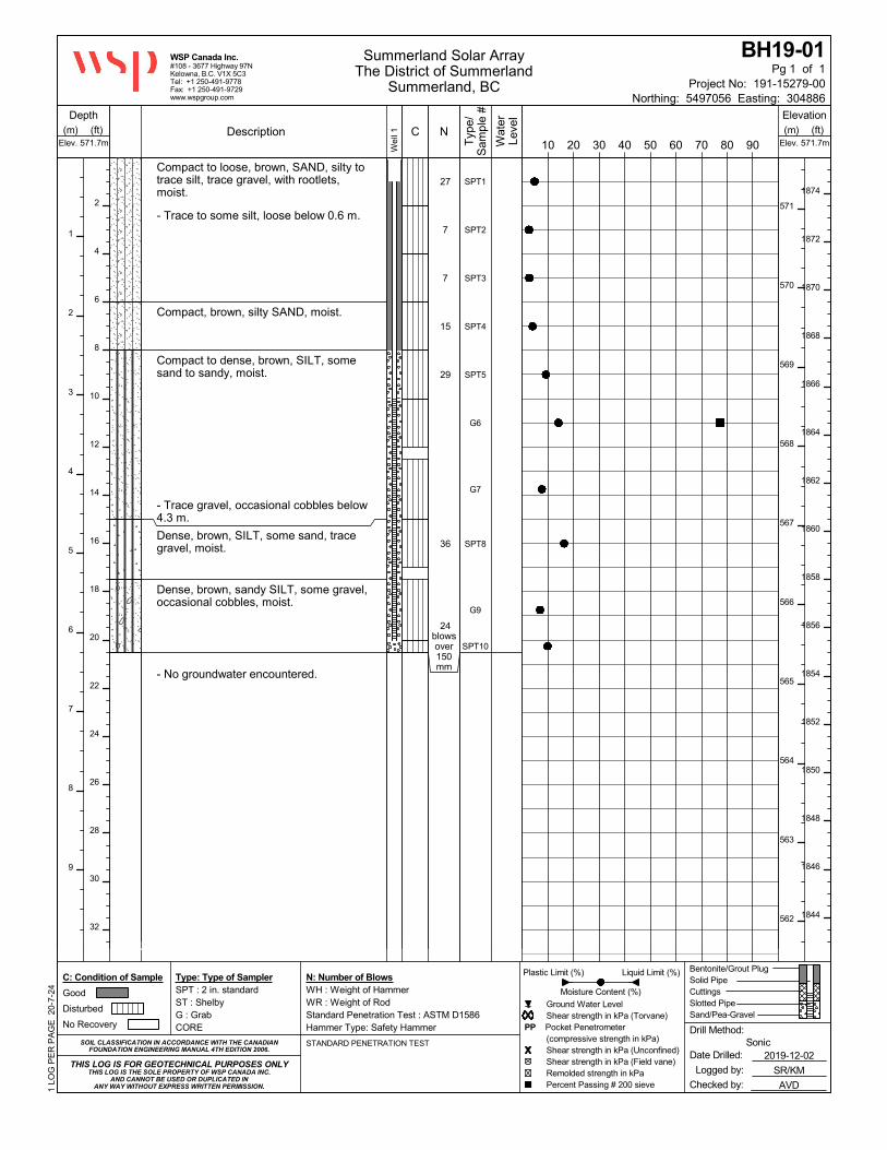
Compact to loose, brown, SAND, silty totrace silt, trace gravel, with rootlets,moist.
- Trace to some silt, loose below 0.6 m.
Compact, brown, silty SAND, moist.
Compact to dense, brown, SILT, somesand to sandy, moist.
- Trace gravel, occasional cobbles below4.3 m.
Dense, brown, SILT, some sand, tracegravel, moist.
Dense, brown, sandy SILT, some gravel,occasional cobbles, moist.
- No groundwater encountered.
SPT1
SPT2
SPT3
SPT4
SPT5
G6
G7
SPT8
G9
SPT10
27
7
7
15
29
36
24blowsover150mm
Elev. 571.7m Elev. 571.7m
BH19-01
Northing: 5497056 Easting: 304886
Pg 1 of 1
Depth Elevation
Type: Type of SamplerSPT : 2 in. standardST : ShelbyG : GrabCORE
SOIL CLASSIFICATION IN ACCORDANCE WITH THE CANADIANFOUNDATION ENGINEERING MANUAL 4TH EDITION 2006.
Checked by: AVD
Date Drilled: 2019-12-02
Logged by: SR/KM
Liquid Limit (%)Plastic Limit (%)
Moisture Content (%)
Ground Water Level Shear strength in kPa (Torvane)PP Pocket Penetrometer (compressive strength in kPa) Shear strength in kPa (Unconfined) Shear strength in kPa (Field vane) Remolded strength in kPa Percent Passing # 200 sieve
Summerland Solar ArrayThe District of Summerland
Summerland, BC
(ft)
2
4
6
8
10
12
14
16
18
20
22
24
26
28
30
32
THIS LOG IS THE SOLE PROPERTY OF WSP CANADA INC.AND CANNOT BE USED OR DUPLICATED IN
ANY WAY WITHOUT EXPRESS WRITTEN PERMISSION.
Drill Method:Sonic
Bentonite/Grout PlugSolid PipeCuttingsSlotted PipeSand/Pea-Gravel
THIS LOG IS FOR GEOTECHNICAL PURPOSES ONLY
C: Condition of Sample
Good
Disturbed
No Recovery
N: Number of BlowsWH : Weight of HammerWR : Weight of RodStandard Penetration Test : ASTM D1586Hammer Type: Safety Hammer
Project No: 191-15279-00
#108 - 3677 Highway 97NKelowna, B.C. V1X 5C3Tel: +1 250-491-9778Fax: +1 250-491-9729www.wspgroup.com
WSP Canada Inc.
(m)
1
2
3
4
5
6
7
8
9
Description
1 LO
G P
ER
PA
GE
20-
7-24
(m)
571
570
569
568
567
566
565
564
563
562
(ft)
1874
1872
1870
1868
1866
1864
1862
1860
1858
1856
1854
1852
1850
1848
1846
1844
Typ
e/S
ampl
e #
Wel
l 1 C10 20 30 40 50 60 70 80 90W
ater
Leve
l
N
STANDARD PENETRATION TEST

Very dense, brown, gravelly SAND FILL,trace silt, with rootlets, moist.
Compact, brown, SAND, trace silt, moist.
Compact, brown, sandy SILT, moist.
Compact, brown, SAND, some silt tosilty, moist.
- Silty below 2.1 m.
Compact, brown, sandy SILT, moist.
Compact, brown, silty SAND, containscobbles, moist.
- No groundwater encountered.
SPT1
SPT2
SPT3
SPT4
SPT5
G6
SPT7
G8
SPT9
68
13
12
11
15
21
25
Elev. 568.5m Elev. 568.5m
BH19-02
Northing: 5497146 Easting: 304886
Pg 1 of 1
Depth Elevation
Type: Type of SamplerSPT : 2 in. standardST : ShelbyG : GrabCORE
SOIL CLASSIFICATION IN ACCORDANCE WITH THE CANADIANFOUNDATION ENGINEERING MANUAL 4TH EDITION 2006.
Checked by: AVD
Date Drilled: 2019-12-02
Logged by: SR/KM
Liquid Limit (%)Plastic Limit (%)
Moisture Content (%)
Ground Water Level Shear strength in kPa (Torvane)PP Pocket Penetrometer (compressive strength in kPa) Shear strength in kPa (Unconfined) Shear strength in kPa (Field vane) Remolded strength in kPa Percent Passing # 200 sieve
Summerland Solar ArrayThe District of Summerland
Summerland, BC
(ft)
2
4
6
8
10
12
14
16
18
20
22
24
26
28
30
32
THIS LOG IS THE SOLE PROPERTY OF WSP CANADA INC.AND CANNOT BE USED OR DUPLICATED IN
ANY WAY WITHOUT EXPRESS WRITTEN PERMISSION.
Drill Method:Sonic
Bentonite/Grout PlugSolid PipeCuttingsSlotted PipeSand/Pea-Gravel
THIS LOG IS FOR GEOTECHNICAL PURPOSES ONLY
C: Condition of Sample
Good
Disturbed
No Recovery
N: Number of BlowsWH : Weight of HammerWR : Weight of RodStandard Penetration Test : ASTM D1586Hammer Type: Safety Hammer
Project No: 191-15279-00
#108 - 3677 Highway 97NKelowna, B.C. V1X 5C3Tel: +1 250-491-9778Fax: +1 250-491-9729www.wspgroup.com
WSP Canada Inc.
(m)
1
2
3
4
5
6
7
8
9
Description
1 LO
G P
ER
PA
GE
20-
7-24
(m)
568
567
566
565
564
563
562
561
560
559
(ft)
1864
1862
1860
1858
1856
1854
1852
1850
1848
1846
1844
1842
1840
1838
1836
1834
Typ
e/S
ampl
e #
Wel
l 1 C10 20 30 40 50 60 70 80 90W
ater
Leve
l
N
STANDARD PENETRATION TEST

ASPHALT (75 mm thick).
Dense, brown to black, sandy SILT FILL,some gravel, moist.
Loose, brown, silty SAND, trace gravel,moist.
- Black below 1.1 m.
Loose to compact, brown, silty SAND,moist.
- Becomes compact
Dense, brown, sandy SILT, some gravel,occasional cobbles, moist, non-cohesive.
- No groundwater encountered.
G1
SPT2
SPT3
SPT4
G5
G6
SPT7
G8
SPT9
8
5
6
41
50blows
over 75mm
Elev. 568.6m Elev. 568.6m
BH19-03
Northing: 5497135 Easting: 304809.3
Pg 1 of 1
Depth Elevation
Type: Type of SamplerSPT : 2 in. standardST : ShelbyG : GrabCORE
SOIL CLASSIFICATION IN ACCORDANCE WITH THE CANADIANFOUNDATION ENGINEERING MANUAL 4TH EDITION 2006.
Checked by: AVD
Date Drilled: 2019-12-02
Logged by: SR/KM
Liquid Limit (%)Plastic Limit (%)
Moisture Content (%)
Ground Water Level Shear strength in kPa (Torvane)PP Pocket Penetrometer (compressive strength in kPa) Shear strength in kPa (Unconfined) Shear strength in kPa (Field vane) Remolded strength in kPa Percent Passing # 200 sieve
Summerland Solar ArrayThe District of Summerland
Summerland, BC
(ft)
2
4
6
8
10
12
14
16
18
20
22
24
26
28
30
32
THIS LOG IS THE SOLE PROPERTY OF WSP CANADA INC.AND CANNOT BE USED OR DUPLICATED IN
ANY WAY WITHOUT EXPRESS WRITTEN PERMISSION.
Drill Method:Sonic
Bentonite/Grout PlugSolid PipeCuttingsSlotted PipeSand/Pea-Gravel
THIS LOG IS FOR GEOTECHNICAL PURPOSES ONLY
C: Condition of Sample
Good
Disturbed
No Recovery
N: Number of BlowsWH : Weight of HammerWR : Weight of RodStandard Penetration Test : ASTM D1586Hammer Type: Safety Hammer
Project No: 191-15279-00
#108 - 3677 Highway 97NKelowna, B.C. V1X 5C3Tel: +1 250-491-9778Fax: +1 250-491-9729www.wspgroup.com
WSP Canada Inc.
(m)
1
2
3
4
5
6
7
8
9
Description
1 LO
G P
ER
PA
GE
20-
7-24
(m)
568
567
566
565
564
563
562
561
560
559
(ft)
1864
1862
1860
1858
1856
1854
1852
1850
1848
1846
1844
1842
1840
1838
1836
1834
Typ
e/S
ampl
e #
Wel
l 1 C10 20 30 40 50 60 70 80 90W
ater
Leve
l
N
STANDARD PENETRATION TEST

Compact, brown, silty SAND FILL, tracegravel, moist.
Compact, brown, gravelly SAND, some silt,dry to moist.
Compact, brown, silty sandy GRAVEL,moist.
Compact, brown, SAND, trace silt, moist.
- Some gravel below 2.3 m.
Compact, brown, SAND, gravelly to somegravel, trace silt, moist.
Compact, brown, silty SAND, moist.
Compact, brown, sandy SILT, moist.
- No groundwater encountered.
SPT1
SPT2
SPT3
SPT4
G5
G6
SPT7
G8
SPT9
27
13
12
15
21
20
Elev. 572.4m Elev. 572.4m
BH19-04
Northing: 5497118 Easting: 304917
Pg 1 of 1
Depth Elevation
Type: Type of SamplerSPT : 2 in. standardST : ShelbyG : GrabCORE
SOIL CLASSIFICATION IN ACCORDANCE WITH THE CANADIANFOUNDATION ENGINEERING MANUAL 4TH EDITION 2006.
Checked by: AVD
Date Drilled: 2019-12-03
Logged by: SR/KM
Liquid Limit (%)Plastic Limit (%)
Moisture Content (%)
Ground Water Level Shear strength in kPa (Torvane)PP Pocket Penetrometer (compressive strength in kPa) Shear strength in kPa (Unconfined) Shear strength in kPa (Field vane) Remolded strength in kPa Percent Passing # 200 sieve
Summerland Solar ArrayThe District of Summerland
Summerland, BC
(ft)
2
4
6
8
10
12
14
16
18
20
22
24
26
28
30
32
THIS LOG IS THE SOLE PROPERTY OF WSP CANADA INC.AND CANNOT BE USED OR DUPLICATED IN
ANY WAY WITHOUT EXPRESS WRITTEN PERMISSION.
Drill Method:Sonic
THIS LOG IS FOR GEOTECHNICAL PURPOSES ONLY
C: Condition of Sample
Good
Disturbed
No Recovery
N: Number of BlowsWH : Weight of HammerWR : Weight of RodStandard Penetration Test : ASTM D1586Hammer Type: Safety Hammer
Project No: 191-15279-00
#108 - 3677 Highway 97NKelowna, B.C. V1X 5C3Tel: +1 250-491-9778Fax: +1 250-491-9729www.wspgroup.com
WSP Canada Inc.
(m)
1
2
3
4
5
6
7
8
9
Description
1 LO
G P
ER
PA
GE
20-
7-24
(m)
572
571
570
569
568
567
566
565
564
563
(ft)
1876
1874
1872
1870
1868
1866
1864
1862
1860
1858
1856
1854
1852
1850
1848
1846
Typ
e/S
ampl
e #
C10 20 30 40 50 60 70 80 90W
ater
Leve
l
N
STANDARD PENETRATION TEST

Dense, brown, SAND FILL, some gravel,some silt, moist.
Compact, brown, silty SAND, trace gravel,moist.
Compact to loose, brown, SAND and SILT,trace gravel, moist.
Compact, brown, SAND, some silt to silty,moist.
- Silty below 4.6 m.
- No groundwater encountered.
SPT1
SPT2
SPT3
SPT4
G5
G6
SPT7
G8
SPT9
39
10
9
11
22
25
Elev. 567.4m Elev. 567.4m
BH19-05
Northing: 5497167 Easting: 304883
Pg 1 of 1
Depth Elevation
Type: Type of SamplerSPT : 2 in. standardST : ShelbyG : GrabCORE
SOIL CLASSIFICATION IN ACCORDANCE WITH THE CANADIANFOUNDATION ENGINEERING MANUAL 4TH EDITION 2006.
Checked by: AVD
Date Drilled: 2019-12-03
Logged by: SR/KM
Liquid Limit (%)Plastic Limit (%)
Moisture Content (%)
Ground Water Level Shear strength in kPa (Torvane)PP Pocket Penetrometer (compressive strength in kPa) Shear strength in kPa (Unconfined) Shear strength in kPa (Field vane) Remolded strength in kPa Percent Passing # 200 sieve
Summerland Solar ArrayThe District of Summerland
Summerland, BC
(ft)
2
4
6
8
10
12
14
16
18
20
22
24
26
28
30
32
THIS LOG IS THE SOLE PROPERTY OF WSP CANADA INC.AND CANNOT BE USED OR DUPLICATED IN
ANY WAY WITHOUT EXPRESS WRITTEN PERMISSION.
Drill Method:Sonic
THIS LOG IS FOR GEOTECHNICAL PURPOSES ONLY
C: Condition of Sample
Good
Disturbed
No Recovery
N: Number of BlowsWH : Weight of HammerWR : Weight of RodStandard Penetration Test : ASTM D1586Hammer Type: Safety Hammer
Project No: 191-15279-00
#108 - 3677 Highway 97NKelowna, B.C. V1X 5C3Tel: +1 250-491-9778Fax: +1 250-491-9729www.wspgroup.com
WSP Canada Inc.
(m)
1
2
3
4
5
6
7
8
9
Description
1 LO
G P
ER
PA
GE
20-
7-24
(m)
567
566
565
564
563
562
561
560
559
558
(ft)
1860
1858
1856
1854
1852
1850
1848
1846
1844
1842
1840
1838
1836
1834
1832
1830
Typ
e/S
ampl
e #
C10 20 30 40 50 60 70 80 90W
ater
Leve
l
N
STANDARD PENETRATION TEST

Drilled out.
Compact, brown, SAND, some silt, moist.
Dense, light brown, SAND, some gravel,trace sand, moist.
Dense, light brown, SAND, some silt, moist.
Very dense, brown, SILT and SAND, tracegravel, moist.- Cobble at 8.7 m.
Very dense, brown to grey, sandy SILTTILL, some gravel, moist.
- No groundwater encountered.
G10
SPT11A
SPT11B
G12
G13
SPT14
38
89
Elev. 568.3m Elev. 568.3m
BH19-05B
Northing: 5497167 Easting: 304883
Pg 1 of 1
Depth Elevation
Type: Type of SamplerSPT : 2 in. standardST : ShelbyG : GrabCORE
SOIL CLASSIFICATION IN ACCORDANCE WITH THE CANADIANFOUNDATION ENGINEERING MANUAL 4TH EDITION 2006.
Checked by: AVD
Date Drilled: 2019-12-04
Logged by: SR
Liquid Limit (%)Plastic Limit (%)
Moisture Content (%)
Ground Water Level Shear strength in kPa (Torvane)PP Pocket Penetrometer (compressive strength in kPa) Shear strength in kPa (Unconfined) Shear strength in kPa (Field vane) Remolded strength in kPa Percent Passing # 200 sieve
Summerland Solar ArrayThe District of Summerland
Summerland, BC
(ft)
2
4
6
8
10
12
14
16
18
20
22
24
26
28
30
32
THIS LOG IS THE SOLE PROPERTY OF WSP CANADA INC.AND CANNOT BE USED OR DUPLICATED IN
ANY WAY WITHOUT EXPRESS WRITTEN PERMISSION.
Drill Method:Sonic
THIS LOG IS FOR GEOTECHNICAL PURPOSES ONLY
C: Condition of Sample
Good
Disturbed
No Recovery
N: Number of BlowsWH : Weight of HammerWR : Weight of RodStandard Penetration Test : ASTM D1586Hammer Type: Safety Hammer
Project No: 191-15279-00
#108 - 3677 Highway 97NKelowna, B.C. V1X 5C3Tel: +1 250-491-9778Fax: +1 250-491-9729www.wspgroup.com
WSP Canada Inc.
(m)
1
2
3
4
5
6
7
8
9
Description
1 LO
G P
ER
PA
GE
20-
7-24
(m)
568
567
566
565
564
563
562
561
560
559
(ft)
1864
1862
1860
1858
1856
1854
1852
1850
1848
1846
1844
1842
1840
1838
1836
1834
1832
Typ
e/S
ampl
e #
C10 20 30 40 50 60 70 80 90W
ater
Leve
l
N

Very dense, brown, SAND and GRAVELFILL, trace silt, moist.
Compact, light brown, SAND, silty to somesilt, trace gravel, moist.
- Some silt below 1.5 m.
Compact, brown, SAND, some gravel, tracesilt, moist.
Compact, brown, silty SAND, moist.
Compact, brown, SAND, some gravel, somesilt, moist.
Dense, brown, SAND, silty to some silt,some gravel to gravelly, moist.- Gravelly, some silt below 5.3 m.
- No groundwater encountered.
SPT1
SPT2
SPT3
SPT4
G5
G6
SPT7
G8
SPT9
59
11
11
21
32
44
Elev. 568.5m Elev. 568.5m
BH19-06
Northing: 5497216 Easting: 304828
Pg 1 of 1
Depth Elevation
Type: Type of SamplerSPT : 2 in. standardST : ShelbyG : GrabCORE
SOIL CLASSIFICATION IN ACCORDANCE WITH THE CANADIANFOUNDATION ENGINEERING MANUAL 4TH EDITION 2006.
Checked by: AVD
Date Drilled: 2019-12-03
Logged by: SR/KM
Liquid Limit (%)Plastic Limit (%)
Moisture Content (%)
Ground Water Level Shear strength in kPa (Torvane)PP Pocket Penetrometer (compressive strength in kPa) Shear strength in kPa (Unconfined) Shear strength in kPa (Field vane) Remolded strength in kPa Percent Passing # 200 sieve
Summerland Solar ArrayThe District of Summerland
Summerland, BC
(ft)
2
4
6
8
10
12
14
16
18
20
22
24
26
28
30
32
THIS LOG IS THE SOLE PROPERTY OF WSP CANADA INC.AND CANNOT BE USED OR DUPLICATED IN
ANY WAY WITHOUT EXPRESS WRITTEN PERMISSION.
Drill Method:Sonic
THIS LOG IS FOR GEOTECHNICAL PURPOSES ONLY
C: Condition of Sample
Good
Disturbed
No Recovery
N: Number of BlowsWH : Weight of HammerWR : Weight of RodStandard Penetration Test : ASTM D1586Hammer Type: Safety Hammer
Project No: 191-15279-00
#108 - 3677 Highway 97NKelowna, B.C. V1X 5C3Tel: +1 250-491-9778Fax: +1 250-491-9729www.wspgroup.com
WSP Canada Inc.
(m)
1
2
3
4
5
6
7
8
9
Description
1 LO
G P
ER
PA
GE
20-
7-24
(m)
568
567
566
565
564
563
562
561
560
559
(ft)
1864
1862
1860
1858
1856
1854
1852
1850
1848
1846
1844
1842
1840
1838
1836
1834
Typ
e/S
ampl
e #
C10 20 30 40 50 60 70 80 90W
ater
Leve
l
N
STANDARD PENETRATION TEST

Dense, brown, SAND and GRAVEL FILLsome silt, moist.
Compact, brown, SAND some silt, tracegravel, moist.
Loose, brown SAND, trace silt, moist.
- Fine to medium sand from 1.5 to 2.0 m.
- Medium to coarse sand below 2.0 m.
Loose, brown, SAND and SILT, moist.
Loose, light brown, SAND, trace to somegravel, trace silt, moist.
Compact, brown, GRAVEL, some sand,trace silt, moist.
- No groundwater encountered.
SPT1A
SPT1B
SPT2
SPT3A
SPT3B
SPT4
SPT5A
SPT5B
SPT6A
SPT6B
SPT7
41
9
7
10
7
17
20
Elev. 569.9m Elev. 569.9m
BH19-07
Northing: 5497234 Easting: 304746
Pg 1 of 1
Depth Elevation
Type: Type of SamplerSPT : 2 in. standardST : ShelbyG : GrabCORE
SOIL CLASSIFICATION IN ACCORDANCE WITH THE CANADIANFOUNDATION ENGINEERING MANUAL 4TH EDITION 2006.
Checked by: AVD
Date Drilled: 2019-12-03
Logged by: SR
Liquid Limit (%)Plastic Limit (%)
Moisture Content (%)
Ground Water Level Shear strength in kPa (Torvane)PP Pocket Penetrometer (compressive strength in kPa) Shear strength in kPa (Unconfined) Shear strength in kPa (Field vane) Remolded strength in kPa Percent Passing # 200 sieve
Summerland Solar ArrayThe District of Summerland
Summerland, BC
(ft)
2
4
6
8
10
12
14
16
18
20
22
24
26
28
30
32
THIS LOG IS THE SOLE PROPERTY OF WSP CANADA INC.AND CANNOT BE USED OR DUPLICATED IN
ANY WAY WITHOUT EXPRESS WRITTEN PERMISSION.
Drill Method:Sonic
THIS LOG IS FOR GEOTECHNICAL PURPOSES ONLY
C: Condition of Sample
Good
Disturbed
No Recovery
N: Number of BlowsWH : Weight of HammerWR : Weight of RodStandard Penetration Test : ASTM D1586Hammer Type: Safety Hammer
Project No: 191-15279-00
#108 - 3677 Highway 97NKelowna, B.C. V1X 5C3Tel: +1 250-491-9778Fax: +1 250-491-9729www.wspgroup.com
WSP Canada Inc.
(m)
1
2
3
4
5
6
7
8
9
Description
1 LO
G P
ER
PA
GE
20-
7-24
(m)
569
568
567
566
565
564
563
562
561
560
(ft)
1868
1866
1864
1862
1860
1858
1856
1854
1852
1850
1848
1846
1844
1842
1840
1838
Typ
e/S
ampl
e #
C10 20 30 40 50 60 70 80 90W
ater
Leve
l
N

Drilled out.
Compact, brown, GRAVEL, some sand,trace silt, occasional cobbles, moist.
Compact, grey and brown, SAND andGRAVEL, trace silt, moist.
Compact, brown, GRAVEL, trace sand,trace silt, occasional cobbles, moist
Dense, grey and brown, SAND andGRAVEL, trace silt, moist.
Compact, brown, SAND, some silt, moist.
Very dense, brown to grey, silty, sandyGRAVEL, moist.
- No groundwater encountered.
G8
SPT9
G10
G11
SPT12
45
58
Elev. 569.9m Elev. 569.9m
BH19-07B
Northing: 5497234 Easting: 304746
Pg 1 of 1
Depth Elevation
Type: Type of SamplerSPT : 2 in. standardST : ShelbyG : GrabCORE
SOIL CLASSIFICATION IN ACCORDANCE WITH THE CANADIANFOUNDATION ENGINEERING MANUAL 4TH EDITION 2006.
Checked by: AVD
Date Drilled: 2019-12-04
Logged by: SR
Liquid Limit (%)Plastic Limit (%)
Moisture Content (%)
Ground Water Level Shear strength in kPa (Torvane)PP Pocket Penetrometer (compressive strength in kPa) Shear strength in kPa (Unconfined) Shear strength in kPa (Field vane) Remolded strength in kPa Percent Passing # 200 sieve
Summerland Solar ArrayThe District of Summerland
Summerland, BC
(ft)
2
4
6
8
10
12
14
16
18
20
22
24
26
28
30
32
THIS LOG IS THE SOLE PROPERTY OF WSP CANADA INC.AND CANNOT BE USED OR DUPLICATED IN
ANY WAY WITHOUT EXPRESS WRITTEN PERMISSION.
Drill Method:Sonic
THIS LOG IS FOR GEOTECHNICAL PURPOSES ONLY
C: Condition of Sample
Good
Disturbed
No Recovery
N: Number of BlowsWH : Weight of HammerWR : Weight of RodStandard Penetration Test : ASTM D1586Hammer Type: Safety Hammer
Project No: 191-15279-00
#108 - 3677 Highway 97NKelowna, B.C. V1X 5C3Tel: +1 250-491-9778Fax: +1 250-491-9729www.wspgroup.com
WSP Canada Inc.
(m)
1
2
3
4
5
6
7
8
9
Description
1 LO
G P
ER
PA
GE
20-
7-24
(m)
569
568
567
566
565
564
563
562
561
560
(ft)
1868
1866
1864
1862
1860
1858
1856
1854
1852
1850
1848
1846
1844
1842
1840
1838
Typ
e/S
ampl
e #
C10 20 30 40 50 60 70 80 90W
ater
Leve
l
N

Compact, dark brown to black, sandy SILTTOPSOIL, moist.
Compact to loose, brown, SAND, trace tosome gravel, trace silt, moist.
- Loose below 0.8 m.
- Sandy GRAVEL below about 1.45 m
Compact to loose, brown, SAND, trace tosome gravel, trace silt, moist.
Loose, brown, SAND, trace to some silt,occasional cobbles, moist.
Compact, brown, SAND, some silt, moist.
Compact, brown, silty SAND, moist.
- Interlayed fine and medium sand below 6.1m.
- No groundwater encountered.
SPT1
SPT2
SPT3
SPT4A
SPT4B
SPT5A
SPT5B
G6
SPT7
G8
SPT9A
SPT9B
26
7
18
9
19
17
24
Elev. 569.2m Elev. 569.2m
BH19-08
Northing: 5497179 Easting: 304792
Pg 1 of 1
Depth Elevation
Type: Type of SamplerSPT : 2 in. standardST : ShelbyG : GrabCORE
SOIL CLASSIFICATION IN ACCORDANCE WITH THE CANADIANFOUNDATION ENGINEERING MANUAL 4TH EDITION 2006.
Checked by: AVD
Date Drilled: 2019-12-04
Logged by: SR
Liquid Limit (%)Plastic Limit (%)
Moisture Content (%)
Ground Water Level Shear strength in kPa (Torvane)PP Pocket Penetrometer (compressive strength in kPa) Shear strength in kPa (Unconfined) Shear strength in kPa (Field vane) Remolded strength in kPa Percent Passing # 200 sieve
Summerland Solar ArrayThe District of Summerland
Summerland, BC
(ft)
2
4
6
8
10
12
14
16
18
20
22
24
26
28
30
32
THIS LOG IS THE SOLE PROPERTY OF WSP CANADA INC.AND CANNOT BE USED OR DUPLICATED IN
ANY WAY WITHOUT EXPRESS WRITTEN PERMISSION.
Drill Method:Sonic
THIS LOG IS FOR GEOTECHNICAL PURPOSES ONLY
C: Condition of Sample
Good
Disturbed
No Recovery
N: Number of BlowsWH : Weight of HammerWR : Weight of RodStandard Penetration Test : ASTM D1586Hammer Type: Safety Hammer
Project No: 191-15279-00
#108 - 3677 Highway 97NKelowna, B.C. V1X 5C3Tel: +1 250-491-9778Fax: +1 250-491-9729www.wspgroup.com
WSP Canada Inc.
(m)
1
2
3
4
5
6
7
8
9
Description
1 LO
G P
ER
PA
GE
20-
7-24
(m)
569
568
567
566
565
564
563
562
561
560
(ft)
1866
1864
1862
1860
1858
1856
1854
1852
1850
1848
1846
1844
1842
1840
1838
1836
Typ
e/S
ampl
e #
C10 20 30 40 50 60 70 80 90W
ater
Leve
l
N
STANDARD PENETRATION TEST

Dense, brown, SAND AND GRAVEL FILL,some silt, moist.
Compact, brown, SAND FILL, some gravel,trace to some silt, moist.
- Some silt below 1.2 m.
Compact, brown, SAND, trace silt, moist.
Compact, light brown, SAND, trace silt tosilty, dry to moist
- Silty below 3.3 m.
- Interlayered silty sand and sand, some siltbelow 4.6 m.
Compact, brown, SAND and SILT, moist.
Compact, brown, SAND, some silt, moist.
- No groundwater encountered.
SPT1
SPT2
SPT3
SPT4
SPT5
G6
SPT7
G8
SPT9A
SPT9B
49
25
14
11
17
17
25
Elev. 570.2m Elev. 570.2m
BH19-09
Northing: 5497120 Easting: 304864
Pg 1 of 1
Depth Elevation
Type: Type of SamplerSPT : 2 in. standardST : ShelbyG : GrabCORE
SOIL CLASSIFICATION IN ACCORDANCE WITH THE CANADIANFOUNDATION ENGINEERING MANUAL 4TH EDITION 2006.
Checked by: AVD
Date Drilled: 2019-12-04
Logged by: SR
Liquid Limit (%)Plastic Limit (%)
Moisture Content (%)
Ground Water Level Shear strength in kPa (Torvane)PP Pocket Penetrometer (compressive strength in kPa) Shear strength in kPa (Unconfined) Shear strength in kPa (Field vane) Remolded strength in kPa Percent Passing # 200 sieve
Summerland Solar ArrayThe District of Summerland
Summerland, BC
(ft)
2
4
6
8
10
12
14
16
18
20
22
24
26
28
30
32
THIS LOG IS THE SOLE PROPERTY OF WSP CANADA INC.AND CANNOT BE USED OR DUPLICATED IN
ANY WAY WITHOUT EXPRESS WRITTEN PERMISSION.
Drill Method:Sonic
THIS LOG IS FOR GEOTECHNICAL PURPOSES ONLY
C: Condition of Sample
Good
Disturbed
No Recovery
N: Number of BlowsWH : Weight of HammerWR : Weight of RodStandard Penetration Test : ASTM D1586Hammer Type: Safety Hammer
Project No: 191-15279-00
#108 - 3677 Highway 97NKelowna, B.C. V1X 5C3Tel: +1 250-491-9778Fax: +1 250-491-9729www.wspgroup.com
WSP Canada Inc.
(m)
1
2
3
4
5
6
7
8
9
Description
1 LO
G P
ER
PA
GE
20-
7-24
(m)
570
569
568
567
566
565
564
563
562
561
(ft)
1870
1868
1866
1864
1862
1860
1858
1856
1854
1852
1850
1848
1846
1844
1842
1840
1838
Typ
e/S
ampl
e #
C10 20 30 40 50 60 70 80 90W
ater
Leve
l
N
STANDARD PENETRATION TEST

Dense, dark brown, silty SAND FILL, traceorganics, moist.
Compact, brown, silty SAND, moist.
Compact, brown, SAND, some silt, moist.
Loose to compact, brown, SAND, trace tosome silt, dry to moist.
Very dense, brown, silty, gravelly, SAND,dry to moist.- Boulder from 2.6 to 3.0 m.
Very dense, brown, silty SAND andGRAVEL TILL, moist.
Possible BEDROCK or BOULDER.
- No groundwater encountered.
SPT1A
SPT1B
SPT1C
SPT2
SPT3
G4
SPT5
SPT6
41
6
14
55
50
Elev. 572.5m Elev. 572.5m
BH19-10
Northing: 5497075 Easting: 304848
Pg 1 of 1
Depth Elevation
Type: Type of SamplerSPT : 2 in. standardST : ShelbyG : GrabCORE
SOIL CLASSIFICATION IN ACCORDANCE WITH THE CANADIANFOUNDATION ENGINEERING MANUAL 4TH EDITION 2006.
Checked by: AVD
Date Drilled: 2019-12-04
Logged by: SR
Liquid Limit (%)Plastic Limit (%)
Moisture Content (%)
Ground Water Level Shear strength in kPa (Torvane)PP Pocket Penetrometer (compressive strength in kPa) Shear strength in kPa (Unconfined) Shear strength in kPa (Field vane) Remolded strength in kPa Percent Passing # 200 sieve
Summerland Solar ArrayThe District of Summerland
Summerland, BC
(ft)
2
4
6
8
10
12
14
16
18
20
22
24
26
28
30
32
THIS LOG IS THE SOLE PROPERTY OF WSP CANADA INC.AND CANNOT BE USED OR DUPLICATED IN
ANY WAY WITHOUT EXPRESS WRITTEN PERMISSION.
Drill Method:Sonic
THIS LOG IS FOR GEOTECHNICAL PURPOSES ONLY
C: Condition of Sample
Good
Disturbed
No Recovery
N: Number of BlowsWH : Weight of HammerWR : Weight of RodStandard Penetration Test : ASTM D1586Hammer Type: Safety Hammer
Project No: 191-15279-00
#108 - 3677 Highway 97NKelowna, B.C. V1X 5C3Tel: +1 250-491-9778Fax: +1 250-491-9729www.wspgroup.com
WSP Canada Inc.
(m)
1
2
3
4
5
6
7
8
9
Description
1 LO
G P
ER
PA
GE
20-
7-24
(m)
572
571
570
569
568
567
566
565
564
563
(ft)
1878
1876
1874
1872
1870
1868
1866
1864
1862
1860
1858
1856
1854
1852
1850
1848
1846
Typ
e/S
ampl
e #
C10 20 30 40 50 60 70 80 90W
ater
Leve
l
N

APPENDIX
C GRAIN SIZE ANALYSES ASTM C136/C136M-19

#108, 3677 Hwy 97N #100, 20339 96 Ave. 12791 Clarke Pl.
Kelowna, BC V1X 5C3 Langley, BC V1M 0E4 Richmond, BC V6V 2H9
Tel: (250) 491-9778 Tel: (604) 533-2992 Tel: (604) 278-1411
Fax: (250) 491-9729 Fax: (604) 533-0768 Fax: (604) 278-1412
Client: File No.:
Project: Phase:
Site Address:
Sample Location: Sampled By:
Supplier: Tested By:
Material Type: Date Sampled:
Usage: Date Tested:
Specification: Sieve No.
5%
Upper
Limit
Lower
Limit
150.0
100.0
75.0
50.0
37.5
25.0
19.0
12.5
9.51
4.75
2.36 100.0%
1.18 99.9%
0.600 99.7%
0.425
0.300 98.9%
0.150 93.1%
0.075 77.3%
Remarks:
WSP Canada Inc.
Reporting of these results constitutes a testing service only.
No engineering interpretation of the results is expressed or implied.
Engineering review and interpretation of these results can be provided upon written request. Per:
Stephen Renner, EIT
Report of Grain Size Analysis
The District of Summerland
Summerland, BC
Screen
Opening
(mm):
%
Passing
Total:
Specification
Summerland Solar Array
December 2, 2019
BH19-01, G6 - 3.0 m
January 17, 2020
sandy SILT
SAR
191-15279-00
SF
Washed Sieve
1
Moisture Content (as received):
2.36 1.18 0.600 0.300
0.150
0.075
4.7
5
0.0
75
10
01
00
10
01
00
10
01
00
10
01
00
10
01
00
10
01
00
10
01
00
10
0
10
00
10
00
10
00
10
00
10
00
10
00
10
00
10
00
10
00
10
00
10
00
10
00
10
00
10
00
10
00
10
.01
0.0
10
.01
0.0
10
.01
0.0
10
.01
0.0
10
.01
0.0
10
.01
0.0
10
.01
0.0
10
.0
1.0
01
.00
1.0
01
.00
1.0
01
.00
1.0
01
.00
1.0
01
.00
1.0
01
.00
1.0
01
.00
1.0
0
0.0
10
0.0
10
0.0
10
0.0
10
0.0
10
0.0
10
0.0
10
0.0
10
0.0
10
0.0
10
0.0
10
0.0
10
0.0
10
0.0
10
0.0
10
0%
10%
20%
30%
40%
50%
60%
70%
80%
90%
100%
Pe
rce
nt P
assin
g
Sieve Opening (mm)
Gravel Sand Silt/Clay
% Passing Total Lower Limit Upper Limit

#108, 3677 Hwy 97N #100, 20339 96 Ave. 12791 Clarke Pl.
Kelowna, BC V1X 5C3 Langley, BC V1M 0E4 Richmond, BC V6V 2H9
Tel: (250) 491-9778 Tel: (604) 533-2992 Tel: (604) 278-1411
Fax: (250) 491-9729 Fax: (604) 533-0768 Fax: (604) 278-1412
Client: File No.:
Project: Phase:
Site Address:
Sample Location: Sampled By:
Supplier: Tested By:
Material Type: Date Sampled:
Usage: Date Tested:
Specification: Sieve No.
4%
Upper
Limit
Lower
Limit
150.0
100.0
75.0
50.0
37.5
25.0
19.0
12.5
9.51
4.75 100.0%
2.36 99.6%
1.18 98.8%
0.600 95.3%
0.425
0.300 82.4%
0.150 58.0%
0.075 34.5%
Remarks:
WSP Canada Inc.
Reporting of these results constitutes a testing service only.
No engineering interpretation of the results is expressed or implied.
Engineering review and interpretation of these results can be provided upon written request. Per:
Stephen Renner, EIT
Report of Grain Size Analysis
The District of Summerland
Summerland, BC
Screen
Opening
(mm):
%
Passing
Total:
Specification
Summerland Solar Array
December 2, 2019
BH19-03, SPT4 - 2.3 m
January 17, 2020
silty SAND
SAR
191-15279-00
SF
Washed Sieve
2
Moisture Content (as received):
4.75 2.36 1.18
0.600
0.300
0.150
0.075
4.7
5
0.0
75
10
01
00
10
01
00
10
01
00
10
01
00
10
01
00
10
01
00
10
01
00
10
0
10
00
10
00
10
00
10
00
10
00
10
00
10
00
10
00
10
00
10
00
10
00
10
00
10
00
10
00
10
00
10
.01
0.0
10
.01
0.0
10
.01
0.0
10
.01
0.0
10
.01
0.0
10
.01
0.0
10
.01
0.0
10
.0
1.0
01
.00
1.0
01
.00
1.0
01
.00
1.0
01
.00
1.0
01
.00
1.0
01
.00
1.0
01
.00
1.0
0
0.0
10
0.0
10
0.0
10
0.0
10
0.0
10
0.0
10
0.0
10
0.0
10
0.0
10
0.0
10
0.0
10
0.0
10
0.0
10
0.0
10
0.0
10
0%
10%
20%
30%
40%
50%
60%
70%
80%
90%
100%
Pe
rce
nt P
assin
g
Sieve Opening (mm)
Gravel Sand Silt/Clay
% Passing Total Lower Limit Upper Limit

#108, 3677 Hwy 97N #100, 20339 96 Ave. 12791 Clarke Pl.
Kelowna, BC V1X 5C3 Langley, BC V1M 0E4 Richmond, BC V6V 2H9
Tel: (250) 491-9778 Tel: (604) 533-2992 Tel: (604) 278-1411
Fax: (250) 491-9729 Fax: (604) 533-0768 Fax: (604) 278-1412
Client: File No.:
Project: Phase:
Site Address:
Sample Location: Sampled By:
Supplier: Tested By:
Material Type: Date Sampled:
Usage: Date Tested:
Specification: Sieve No.
6%
Upper
Limit
Lower
Limit
150.0
100.0
75.0
50.0
37.5
25.0
19.0
12.5
9.51
4.75
2.36
1.18 100.0%
0.600 99.3%
0.425
0.300 96.1%
0.150 64.0%
0.075 13.2%
Remarks:
WSP Canada Inc.
Reporting of these results constitutes a testing service only.
No engineering interpretation of the results is expressed or implied.
Engineering review and interpretation of these results can be provided upon written request. Per:
Stephen Renner, EIT
Report of Grain Size Analysis
The District of Summerland
Summerland, BC
Screen
Opening
(mm):
%
Passing
Total:
Specification
Summerland Solar Array
December 4, 2019
BH19-05B, G10 - 6.7 m
January 17, 2020
SAND, some silt
SLR
191-15279-00
SF
Washed Sieve
3
Moisture Content (as received):
1.18 0.600
0.300
0.150
0.075
4.7
5
0.0
75
10
01
00
10
01
00
10
01
00
10
01
00
10
01
00
10
01
00
10
01
00
10
0
10
00
10
00
10
00
10
00
10
00
10
00
10
00
10
00
10
00
10
00
10
00
10
00
10
00
10
00
10
00
10
.01
0.0
10
.01
0.0
10
.01
0.0
10
.01
0.0
10
.01
0.0
10
.01
0.0
10
.01
0.0
10
.0
1.0
01
.00
1.0
01
.00
1.0
01
.00
1.0
01
.00
1.0
01
.00
1.0
01
.00
1.0
01
.00
1.0
0
0.0
10
0.0
10
0.0
10
0.0
10
0.0
10
0.0
10
0.0
10
0.0
10
0.0
10
0.0
10
0.0
10
0.0
10
0.0
10
0.0
10
0.0
10
0%
10%
20%
30%
40%
50%
60%
70%
80%
90%
100%
Pe
rce
nt P
assin
g
Sieve Opening (mm)
Gravel Sand Silt/Clay
% Passing Total Lower Limit Upper Limit

#108, 3677 Hwy 97N #100, 20339 96 Ave. 12791 Clarke Pl.
Kelowna, BC V1X 5C3 Langley, BC V1M 0E4 Richmond, BC V6V 2H9
Tel: (250) 491-9778 Tel: (604) 533-2992 Tel: (604) 278-1411
Fax: (250) 491-9729 Fax: (604) 533-0768 Fax: (604) 278-1412
Client: File No.:
Project: Phase:
Site Address:
Sample Location: Sampled By:
Supplier: Tested By:
Material Type: Date Sampled:
Usage: Date Tested:
Specification: Sieve No.
8%
Upper
Limit
Lower
Limit
150.0
100.0
75.0
50.0
37.5
25.0
19.0
12.5
9.51
4.75
2.36
1.18
0.600 100.0%
0.425
0.300 100.0%
0.150 94.4%
0.075 47.7%
Remarks:
WSP Canada Inc.
Reporting of these results constitutes a testing service only.
No engineering interpretation of the results is expressed or implied.
Engineering review and interpretation of these results can be provided upon written request. Per:
Stephen Renner, EIT
Report of Grain Size Analysis
The District of Summerland
Summerland, BC
Screen
Opening
(mm):
%
Passing
Total:
Specification
Summerland Solar Array
December 3, 2019
BH19-07, SPT4 - 1.4 m
January 17, 2020
SAND and SILT
SLR
191-15279-00
SF
Washed Sieve
4
Moisture Content (as received):
0.600 0.300
0.150
0.075
4.7
5
0.0
75
10
01
00
10
01
00
10
01
00
10
01
00
10
01
00
10
01
00
10
01
00
10
0
10
00
10
00
10
00
10
00
10
00
10
00
10
00
10
00
10
00
10
00
10
00
10
00
10
00
10
00
10
00
10
.01
0.0
10
.01
0.0
10
.01
0.0
10
.01
0.0
10
.01
0.0
10
.01
0.0
10
.01
0.0
10
.0
1.0
01
.00
1.0
01
.00
1.0
01
.00
1.0
01
.00
1.0
01
.00
1.0
01
.00
1.0
01
.00
1.0
0
0.0
10
0.0
10
0.0
10
0.0
10
0.0
10
0.0
10
0.0
10
0.0
10
0.0
10
0.0
10
0.0
10
0.0
10
0.0
10
0.0
10
0.0
10
0%
10%
20%
30%
40%
50%
60%
70%
80%
90%
100%
Pe
rce
nt P
assin
g
Sieve Opening (mm)
Gravel Sand Silt/Clay
% Passing Total Lower Limit Upper Limit

#108, 3677 Hwy 97N #100, 20339 96 Ave. 12791 Clarke Pl.
Kelowna, BC V1X 5C3 Langley, BC V1M 0E4 Richmond, BC V6V 2H9
Tel: (250) 491-9778 Tel: (604) 533-2992 Tel: (604) 278-1411
Fax: (250) 491-9729 Fax: (604) 533-0768 Fax: (604) 278-1412
Client: File No.:
Project: Phase:
Site Address:
Sample Location: Sampled By:
Supplier: Tested By:
Material Type: Date Sampled:
Usage: Date Tested:
Specification: Sieve No.
5%
Upper
Limit
Lower
Limit
150.0
100.0
75.0
50.0
37.5
25.0
19.0
12.5
9.51
4.75 100.0%
2.36 99.4%
1.18 98.8%
0.600 98.2%
0.425
0.300 93.8%
0.150 50.2%
0.075 26.3%
Remarks:
WSP Canada Inc.
Reporting of these results constitutes a testing service only.
No engineering interpretation of the results is expressed or implied.
Engineering review and interpretation of these results can be provided upon written request. Per:
Stephen Renner, EIT
Report of Grain Size Analysis
The District of Summerland
Summerland, BC
Screen
Opening
(mm):
%
Passing
Total:
Specification
Summerland Solar Array
December 4, 2019
BH19-09, SPT5 - 3.0 m
January 17, 2020
silty SAND
SLR
191-15279-00
SF
Washed Sieve
5
Moisture Content (as received):
4.75 2.36 1.18 0.600
0.300
0.150
0.075
4.7
5
0.0
75
10
01
00
10
01
00
10
01
00
10
01
00
10
01
00
10
01
00
10
01
00
10
0
10
00
10
00
10
00
10
00
10
00
10
00
10
00
10
00
10
00
10
00
10
00
10
00
10
00
10
00
10
00
10
.01
0.0
10
.01
0.0
10
.01
0.0
10
.01
0.0
10
.01
0.0
10
.01
0.0
10
.01
0.0
10
.0
1.0
01
.00
1.0
01
.00
1.0
01
.00
1.0
01
.00
1.0
01
.00
1.0
01
.00
1.0
01
.00
1.0
0
0.0
10
0.0
10
0.0
10
0.0
10
0.0
10
0.0
10
0.0
10
0.0
10
0.0
10
0.0
10
0.0
10
0.0
10
0.0
10
0.0
10
0.0
10
0%
10%
20%
30%
40%
50%
60%
70%
80%
90%
100%
Pe
rce
nt P
assin
g
Sieve Opening (mm)
Gravel Sand Silt/Clay
% Passing Total Lower Limit Upper Limit

APPENDIX
D SOIL RESISTIVITY TESTS

Client: District of Summerland File No.: 191-15279-00Project: Summerland Solar Array Task: 03
Site Address: Summerland, BC
Sampled By: SLR
Tested By: ARP
Date Sampled: 3/4-Dec-2019
Date Tested: 24-Dec-2019
Sample ID Sample Description pHRedox(mV)
Sulfides MoistureAWWA C105
Appendix A ScoreBH19-07 (1.1-1.5 m) brown Sand 7.1 244 None Moist 1
BH19-08 (1.1-1.4 m) brown Sand 6.9 257 None Moist 1
BH19-09 (1.1-1.4 m) brown Sand 7.7 273 None Moist 1
BH19-10 (0.8 - 1.1 m) brown Sand 6.6 283 None Moist 1
Remarks:
WSP Canada Inc.Reporting of these results constitutes a testing service only.
No engineering interpretation of the results is expressed or implied.
Engineering review and interpretation of these results can be provided upon written request. Per:Anton Parsons, A.Sc.T.
Samples tested in as received condition.
WSP CANADA INC.
100-20339 96 AvenueLangley, BC V1M 0E4
T: 604.533.2992
Report of AWWA C105 Electrochemical Soil Corrosion
322050
305375
129375
131625
Resistivity(ohm-cm)

APPENDIX
E SOIL ANALYTICAL TESTS

[ T hi s r e p o rt s h all n ot b e r e p r o d u c e d e x c e pt i n f ull wit h o ut t h e w ritt e n a ut h o rit y of t h e L a b o r at o r y.]
1 0 - D E C - 1 9
L a b W o r k O r d e r #: L 2 3 9 4 2 0 4
D at e R e c ei v e d:W S P C a n a d a I n c.
U nit 1 0 8 - 3 6 7 7 Hi g h w a y 9 7 N
K el o w n a B C V 1 X 5 C 3
A T T N: St e p h e n R e n n e rFI N A L 0 6 -J A N - 2 0 1 7: 0 2 ( M T)R e p o rt D at e:
V e r si o n:
C e r ti fi c a t e o f A n al y si s
A L S C A N A D A L T D P a rt of t h e A L S G r o u p A n A L S Li mit e d C o m p a n y
_ _ _ _ _ _ _ _ _ _ _ _ _ _ _ _ _ _ _ _ _ _ _ _ _ _ _ _ _ _ _ _ _ _ _ _ _ _ _ _ _ _ _ _
C a rl a F u gi n s kiA c c o u nt M a n a g e r
A D D R E S S: 8 0 8 1 L o u g h e e d H w y, S uit e 1 0 0, B u r n a b y, B C V 5 A 1 W 9 C a n a d a | P h o n e: + 1 6 0 4 2 5 3 4 1 8 8 | F a x: + 1 6 0 4 2 5 3 6 7 0 0
Cli e nt P h o n e: 2 5 0 - 4 9 1 - 9 7 7 8
Pl e a s e fi n d s u bl et d at a att a c h e d at t h e b a c k of t hi s r e p o rt.C o m m e n t s:
1 9 1 - 1 5 2 7 7 - 0 0J o b R ef e r e n c e:
N O T S U B MI T T E DP r oj e ct P. O. #:
1 7 - 7 8 6 8 9 9C of C N u m b e r s:
L e g al Sit e D e s c:

0 6- J A N- 2 0 1 7: 0 2 ( M T)
S a m pl e I D
D e s cri pti o n
Cli e nt I D
S a m pl e d D at e
Gr o u pi n g A n al yt e
S a m pl e d Ti m e
A L S E N VI R O N M E N T A L A N A L Y TI C A L R E P O R T
L 2 3 9 4 2 0 4 C O N T D....
2P A G E of
V er si o n: FI N A L
3

R ef e r e n c e I nf o r m ati o n0 6- J A N- 2 0 1 7: 0 2 ( M T)
L 2 3 9 4 2 0 4 C O N T D....
3P A G E of
A L S T e st C o d e T e st D e s cri pti o n M et h o d R ef er e n c e**
** A L S t e st m et h o d s m a y i n c or p or at e m o difi c ati o n s fr o m s p e cifi e d r ef er e n c e m et h o d s t o i m pr o v e p erf or m a n c e.
M atri x
T h e l a st t w o l ett er s of t h e a b o v e t e st c o d e( s) i n di c at e t h e l a b or at or y t h at p erf or m e d a n al yti c al a n al y si s f or t h at t e st. R ef er t o t h e li st b el o w:
L a b or at or y D efi niti o n C o d e L a b or at or y L o c ati o n
G L O S S A R Y O F R E P O R T T E R M SS urr o g at e - A c o m p o u n d t h at i s si mil ar i n b e h a vi o ur t o t ar g et a n al yt e( s), b ut t h at d o e s n ot o c c ur n at ur all y i n e n vir o n m e nt al s a m pl e s. F ora p pli c a bl e t e st s, s urr o g at e s ar e a d d e d t o s a m pl e s pri or t o a n al y si s a s a c h e c k o n r e c o v er y.m g/ k g - milli gr a m s p er kil o gr a m b a s e d o n dr y w ei g ht of s a m pl e.m g/ k g w wt - milli gr a m s p er kil o gr a m b a s e d o n w et w ei g ht of s a m pl e.m g/ k g l wt - milli gr a m s p er kil o gr a m b a s e d o n li pi d- a dj u st e d w ei g ht of s a m pl e.m g/ L - milli gr a m s p er litr e.< - L e s s t h a n.D. L. - T h e r e p ort e d D et e cti o n Li mit, al s o k n o w n a s t h e Li mit of R e p orti n g ( L O R).N/ A - R e s ult n ot a v ail a bl e. R ef er t o q u alifi er c o d e a n d d efi niti o n f or e x pl a n ati o n.
T e st r e s ult s r e p ort e d r el at e o nl y t o t h e s a m pl e s a s r e c ei v e d b y t h e l a b or at or y.U N L E S S O T H E R WI S E S T A T E D, A L L S A M P L E S W E R E R E C EI V E D I N A C C E P T A B L E C O N DI TI O N.A n al yti c al r e s ult s i n u n si g n e d t e st r e p ort s wit h t h e D R A F T w at er m ar k ar e s u bj e ct t o c h a n g e, p e n di n g fi n al Q C r e vi e w.
T e st M et h o d R ef er e n c e s:
C h ai n of C u st o d y N u m b er s:
1 7- 7 8 6 8 9 9
V er si o n: FI N A L
3

REPORTED TO ALS Environmental (Burnaby)
Burnaby, BC V5A 1W9
Authorized By:
#110 4011 Viking Way Richmond, BC V6V 2K9 | #102 3677 Highway 97N Kelowna, BC V1X 5C3 | 17225 109 Avenue Edmonton, AB T5S 1H7
1-888-311-8846 | www.caro.ca
Suite 100 8081 Lougheed Highway
Junior Account Manager
Alana Crump
CERTIFICATE OF ANALYSIS
Introduction:
CARO Analytical Services is a testing laboratory full of smart, engaged scientists driven to make the world a safer and
healthier place. Through our clients' projects we become an essential element for a better world. We employ methods
conducted in accordance with recognized professional standards using accepted testing methodologies and quality
control efforts. CARO is accredited by the Canadian Association for Laboratories Accreditation (CALA) to ISO
17025:2005 for specific tests listed in the scope of accreditation approved by CALA.
Big Picture Sidekicks
You know that the sample you collected after
snowshoeing to site, digging 5 meters, and
racing to get it on a plane so you can submit it
to the lab for time sensitive results needed to
make important and expensive decisions
(whew) is VERY important. We know that too.
We've Got Chemistry
It�s simple. We figure the more you
enjoy working with our fun and
engaged team members; the more
likely you are to give us continued
opportunities to support you.
Ahead of the Curve
T h r o u g h r e s e a r c h , r e g u l a t i o n
knowledge, and instrumentation, we
are your analytical centre for the
technica l knowledge you need,
BEFORE you need it, so you can stay
up to date and in the know.
ATTENTION Carla Fuginski
PO NUMBER L2394204
PROJECT Soil Testing
RECEIVED / TEMP 2019-12-18 10:15 / 10°C
REPORTED 2020-01-06 14:45
PROJECT INFO COC NUMBER L2394204
WORK ORDER 9121653
If you have any questions or concerns, please contact me at [email protected]
Page 1 of 4Rev 2017-11-07 Caring About Results, Obviously. Page 1 of 4

REPORTED TO ALS Environmental (Burnaby)
REPORTED 2020-01-06 14:45
TEST RESULTS
PROJECT Soil Testing
WORK ORDER 9121653
Analyte Result RL Units Analyzed Qualifier
L2394204-1 (9121653-01) | Matrix: Soil | Sampled: 2019-12-03 08:40
General Parameters
%< 0.050Sulfate, Water-Soluble 2020-01-050.050
% wet11.1Moisture 2019-12-201.0 HT1
L2394204-2 (9121653-02) | Matrix: Soil | Sampled: 2019-12-03 09:55
General Parameters
%< 0.050Sulfate, Water-Soluble 2020-01-050.050
% wet3.8Moisture 2019-12-201.0 HT1
L2394204-3 (9121653-03) | Matrix: Soil | Sampled: 2019-12-03 10:50
General Parameters
%< 0.050Sulfate, Water-Soluble 2020-01-050.050
% wet2.9Moisture 2019-12-201.0 HT1
Sample Qualifiers:
HT1 The sample was prepared and/or analyzed past the recommended holding time.
Page 2 of 4Rev 2017-11-07 Caring About Results, Obviously. Page 2 of 4

REPORTED TO ALS Environmental (Burnaby)
REPORTED 2020-01-06 14:45
APPENDIX 1: SUPPORTING INFORMATION
PROJECT Soil Testing
WORK ORDER 9121653
Technique LocationAnalysis Description Method Ref.
Moisture in Soil ASTM D2974-87* Gravimetry (Dried at 105C) N/A
Sulfate, Water-Soluble in Soil CSA A23.2-3B / CSA
A23.2-2B
Extraction (HCl) / Gravimetry (Barium Sulfate Precipitation) Richmond
Note: An asterisk in the Method Reference indicates that the CARO method has been modified from the reference method
Glossary of Terms:
RL Reporting Limit (default)
Percent%
Percent (as received basis)% wet
Less than the specified Reporting Limit (RL) - the actual RL may be higher than the default RL due to various factors<
ASTM ASTM International Test Methods
CSA Canadian Standards Association Chemical Test Methods
The results in this report apply to the samples analyzed in accordance with the Chain of Custody document. This
analytical report must be reproduced in its entirety. CARO is not responsible for any loss or damage resulting directly or
indirectly from error or omission in the conduct of testing. Liability is limited to the cost of analysis. Samples will be
disposed of 30 days after the test report has been issued unless otherwise agreed to in writing.
Results in Bold indicate values that are above CARO's method reporting limits. Any results that are above regulatory
limits are highlighted red. Please note that results will only be highlighted red if the regulatory limits are included on the
CARO report. Any Bold and/or highlighted results do not take into account method uncertainty. If you would like method
uncertainty or regulatory limits to be included on your report, please contact your Account Manager:[email protected]
General Comments:
Page 3 of 4Rev 2017-11-07 Caring About Results, Obviously. Page 3 of 4

REPORTED TO ALS Environmental (Burnaby)
REPORTED 2020-01-06 14:45
APPENDIX 2: QUALITY CONTROL RESULTS
PROJECT Soil Testing
WORK ORDER 9121653
The following section displays the quality control (QC) data that is associated with your sample data. Groups of samples are prepared
in �batches� and analyzed in conjunction with QC samples that ensure your data is of the highest quality. Common QC types include:
� Method Blank (Blk): A blank sample that undergoes sample processing identical to that carried out for the test samples. Method
blank results are used to assess contamination from the laboratory environment and reagents.
� Duplicate (Dup): An additional or second portion of a randomly selected sample in the analytical run carried through the entire
analytical process. Duplicates provide a measure of the analytical method's precision (reproducibility).
� Blank Spike (BS): A sample of known concentration which undergoes processing identical to that carried out for test samples, a l so
referred to as a laboratory control sample (LCS). Blank spikes provide a measure of the analytical method's accuracy.
� Matrix Spike (MS): A second aliquot of sample is fortified with with a known concentration of target analytes and carried through
the entire analytical process. Matrix spikes evaluate potential matrix effects that may affect the analyte recovery.
� Reference Material (SRM): A homogenous material of similar matrix to the samples, certified for the parameter(s) listed.
Reference Materials ensure that the analytical process is adequate to achieve acceptable recoveries of the parameter(s) tested.
Each QC type is analyzed at a 5-10% frequency, i.e. one blank/duplicate/spike for every 10-20 samples. For all types of QC, the
specified recovery (% Rec) and relative percent difference (RPD) limits are derived from long-term method performance averages
and/or prescribed by the reference method.
Analyte Result RL UnitsSpike
Level
Source
Result% REC
REC
Limit% RPD
RPD
LimitQualifier
General Parameters, Batch B9L2178
Blank (B9L2178-BLK1) Prepared: 2019-12-30, Analyzed: 2020-01-05
%Sulfate, Water-Soluble < 0.050 0.050
Duplicate (B9L2178-DUP1) Prepared: 2019-12-30, Analyzed: 2020-01-05Source: 9121653-01
%Sulfate, Water-Soluble < 0.050< 0.050 190.050
Page 4 of 4Rev 2017-11-07 Caring About Results, Obviously. Page 4 of 4
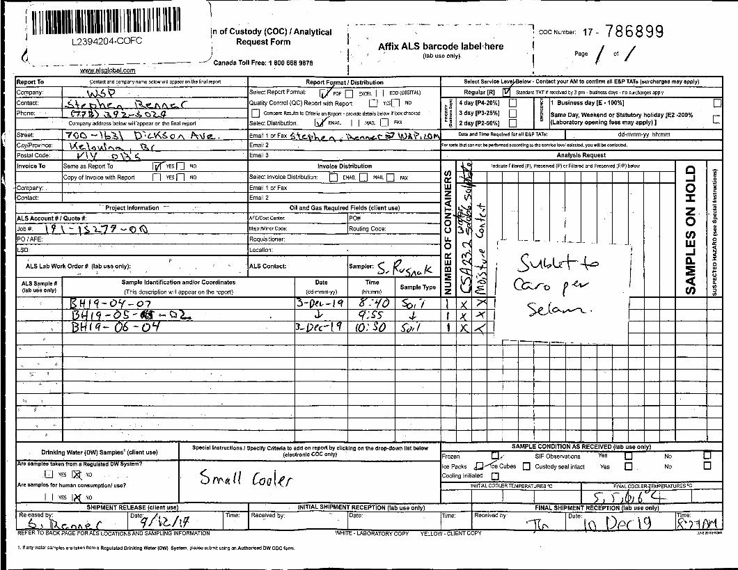

APPENDIX
F 2015 NATIONAL BUILDING CODE SEISMIC HAZARD VALUES

2015 National Building Code Seismic Hazard CalculationINFORMATION: Eastern Canada English (613) 995-5548 français (613) 995-0600 Facsimile (613) 992-8836
Western Canada English (250) 363-6500 Facsimile (250) 363-6565
Site: 49.595N 119.701W User File Reference: Summerland Solar Array
Requested by: Marisa Loude, WSP Canada Inc.
2020-02-02 05:51 UT
Probability of exceedance per annum 0.000404 0.001 0.0021 0.01
Probability of exceedance in 50 years 2 % 5 % 10 % 40 %
Sa (0.05) 0.086 0.053 0.035 0.012
Sa (0.1) 0.127 0.078 0.050 0.018
Sa (0.2) 0.162 0.104 0.070 0.028
Sa (0.3) 0.159 0.107 0.075 0.032
Sa (0.5) 0.141 0.097 0.069 0.030
Sa (1.0) 0.104 0.070 0.049 0.021
Sa (2.0) 0.072 0.046 0.031 0.013
Sa (5.0) 0.032 0.018 0.011 0.004
Sa (10.0) 0.010 0.006 0.004 0.002
PGA (g) 0.075 0.048 0.031 0.011
PGV (m/s) 0.133 0.083 0.055 0.021
Notes: Spectral (Sa(T), where T is the period in seconds) and peak ground acceleration (PGA) values aregiven in units of g (9.81 m/s2). Peak ground velocity is given in m/s. Values are for "firm ground"(NBCC2015 Site Class C, average shear wave velocity 450 m/s). NBCC2015 and CSAS6-14 values arehighlighted in yellow. Three additional periods are provided - their use is discussed in the NBCC2015Commentary. Only 2 significant figures are to be used. These values have been interpolated from a10-km-spaced grid of points. Depending on the gradient of the nearby points, values at thislocation calculated directly from the hazard program may vary. More than 95 percent ofinterpolated values are within 2 percent of the directly calculated values.
References
National Building Code of Canada 2015 NRCC no. 56190; Appendix C: Table C-3, Seismic DesignData for Selected Locations in Canada
Structural Commentaries (User's Guide - NBC 2015: Part 4 of Division B)Commentary J: Design for Seismic Effects
Geological Survey of Canada Open File 7893 Fifth Generation Seismic Hazard Model for Canada: Gridvalues of mean hazard to be used with the 2015 National Building Code of Canada
See the websites www.EarthquakesCanada.ca and www.nationalcodes.ca for more information

APPENDIX
G TERMS OF REFERENCE FOR GEOTECHNICAL REPORT

TERMS OF REFERENCE FOR GEOTECHNICAL REPORTS
ISSUED BY WSP CANADA INC.
Page 1© WSP Canada Inc., 2017 Rev.: GEO Lev May 2017
1 STANDARD OF CARE WSP Canada Inc. (“WSP”) prepared and issued this geotechnical report (the “Report”) for its client (the “Client”) in accordance with generally-accepted engineering consulting practices for the geotechnical discipline. No other warranty, expressed or implied, is made. Unless specifically stated in the Report, the Report does not address environmental issues.
The terms of reference for geotechnical reports issued by WSP (the “Terms of Reference”) contained in the present document provide additional information and caution related to standard of care and the use of the Report. The Client should read and familiarize itself with these Terms of Reference.
2 COMPLETENESS OF THE REPORT All documents, records, drawings, correspondence, data, files and deliverables, whether hard copy, electronic or otherwise, generated as part of the services for the Client are inherent components of the Report and, collectively, form the instruments of professional services (the “Instruments of Professional Services”). The Report is of a summary nature and is not intended to stand alone without reference to the instructions given to WSP by the Client, the communications between WSP and the Client, and to any other reports, writings, proposals or documents prepared by WSP for the Client relative to the specific site described in the Report, all of which constitute the Report.
TO PROPERLY UNDERSTAND THE INFORMATION, OBSERVATIONS, FINDINGS, SUGGESTIONS, RECOMMENDATIONS AND OPINIONS CONTAINED IN THE REPORT, REFERENCE MUST BE MADE TO THE WHOLE OF THE REPORT. WSP CANNOT BE RESPONSIBLE FOR USE BY ANY PARTY OF PORTIONS OF THE REPORT WITHOUT REFERENCE TO THE WHOLE REPORT AND ITS VARIOUS COMPONENTS.
3 BASIS OF THE REPORT WSP prepared the Report for the Client for the specific site, development, building, design or building assessment objectives and purpose that the Client described to WSP. The applicability and reliability of any of the information, observations, findings, suggestions, recommendations and opinions contained in the Report are only valid to the extent that there was no material alteration to or variation from any of the said descriptions provided by the Client to WSP unless the Client specifically requested WSP to review and revise the Report in light of such alteration or variation.
4 USE OF THE REPORT The information, observations, findings, suggestions, recommendations and opinions contained in the Report, or any component forming the Report, are for the sole use and benefit of the Client and the team of consultants selected by the Client for the specific project that the Report was provided. NO OTHER PARTY MAY USE OR RELY UPON THE REPORT OR ANY PORTION OR COMPONENT WITHOUT THE WRITTEN CONSENT OF WSP. WSP will consent to any reasonable request by the Client to approve the use of this Report by other parties designated by the Client as the “Approved Users”. As a condition for the consent of WSP to approve the use of the Report by an Approved User, the Client must provide a copy of these Terms of Reference to that Approved User and the Client must obtain written confirmation from that Approved User that the Approved User will comply with these Terms of Reference, such written confirmation to be provided separately by each Approved User prior to beginning use of the Report. The Client will provide WSP with a copy of the written confirmation from an Approved User when it becomes available to the Client, and in any case, within two weeks of the Client receiving such written confirmation.
The Report and all its components remain the copyright property of WSP and WSP authorises only the Client and the Approved Users to make copies of the Report, but only in such quantities as are reasonably necessary for the use of the Report by the Client and the Approved Users. The Client and the Approved Users may not give, lend, sell or otherwise disseminate or make the Report, or any portion thereof, available to any party without the written permission of WSP. Any use which a third party makes of the Report, or any portion of the Report, is the sole responsibility of such third parties. WSP accepts no responsibility for damages suffered by any third party resulting from the use of the Report. The Client and the Approved Users acknowledge and agree to indemnify and hold harmless WSP, its officers, directors, employees, agents, representatives or sub-consultants, or any or all of them, against any claim of any nature whatsoever brought against WSP by any third parties, whether in contract or in tort, arising or related to the use of contents of the Report.
5 INTERPRETATION OF THE REPORT a. Nature and Exactness of Descriptions: The classification and identification of soils, rocks and geological units, as well as
engineering assessments and estimates have been based on investigations performed in accordance with the standards set out in Paragraph 1 above. The classification and identification of these items are judgmental in nature and even comprehensive sampling and testing programs, implemented with the appropriate equipment by experienced personnel,

Page 2 © WSP Canada Inc., 2017 Rev.: GEO Lev May 2017
may fail to locate some conditions. All investigations or assessments utilizing the standards of Paragraph 1 involve an inherent risk that some conditions will not be detected and all documents or records summarizing such investigations will be based on assumptions of what exists between the actual points sampled. Actual conditions may vary significantly between the points investigated and all persons making use of such documents or records should be aware of, and accept, this risk. Some conditions are subject to changes over time and the parties making use of the Report should be aware of this possibility and understand that the Report only presents the conditions at the sampled points at the time of sampling. Where special concerns exist, or when the Client has special considerations or requirements, the Client must disclose them to WSP so that additional or special investigations may be undertaken, which would not otherwise be within the scope of investigations made by WSP or the purposes of the Report.
b. Reliance on information: The evaluation and conclusions contained in the Report have been prepared on the basis of conditions in evidence at the time of site investigation and field review and on the basis of information provided to WSP. WSP has relied in good faith upon representations, information and instructions provided by the Client and others concerning the site. Accordingly, WSP cannot accept responsibility for any deficiency, misstatement or inaccuracy contained in the report as a result of misstatements, omissions, misrepresentations or fraudulent acts of persons providing information.
c. Additional Involvement by WSP: To avoid misunderstandings, WSP should be retained to assist other professionals to explain relevant engineering findings and to review the geotechnical aspects of the plans, drawings and specifications of other professionals relative to the engineering issues pertaining to the geotechnical consulting services provided by WSP. To ensure compliance and consistency with the applicable building codes, legislation, regulations, guidelines and generally-accepted practices, WSP should also be retained to provide field review services during the performance of any related work. Where applicable, it is understood that such field review services must meet or exceed the minimum necessary requirements to ascertain that the work being carried out is in general conformity with the recommendations made by WSP. Any reduction from the level of services recommended by WSP will result in WSP providing qualified opinions regarding adequacy of the work.
6 ALTERNATE REPORT FORMAT When WSP submits both electronic and hard copy versions of the Instruments of Professional Services, the Client agrees that only the signed and sealed hard copy versions shall be considered final and legally binding upon WSP. The hard copy versions submitted by WSP shall be the original documents for record and working purposes, and, in the event of a dispute or discrepancy, the hard copy versions shall govern over the electronic versions; furthermore, the Client agrees and waives all future right of dispute that the original hard copy signed and sealed versions of the Instruments of Professional Services maintained or retained, or both, by WSP shall be deemed to be the overall originals for the Project.
The Client agrees that the electronic file and hard copy versions of Instruments of Professional Services shall not, under any circumstances, no matter who owns or uses them, be altered by any party except WSP. The Client warrants that the Instruments of Professional Services will be used only and exactly as submitted by WSP.
The Client recognizes and agrees that WSP prepared and submitted electronic files using specific software or hardware systems, or both. WSP makes no representation about the compatibility of these files with the current or future software and hardware systems of the Client, the Approved Users or any other party. The Client further agrees that WSP is under no obligation, unless otherwise expressly specified, to provide the Client, the Approved Users and any other party, or any or all of them, with specific software and hardware systems that are compatible with any electronic submitted by WSP. The Client further agrees that should the Client, an Approved User or a third party require WSP to provide specific software or hardware systems, or both, compatible with the electronic files prepared and submitted by WSP, for any reason whatsoever included but not restricted to an order from a court, then the Client will pay WSP for all reasonable costs related to the provision of the specific software or hardware systems, or both. The Client further agrees to indemnify and hold harmless WSP, its officers, directors, employees, agents, representative or sub-consultant, or any or all of them, against any claim or any nature whatsoever brought against WSP, whether in contract or in tort, arising or related to the provision or use or any specific software or hardware provided by WSP.