geotechnical engineering report - cityoflaredo.com engineering report ... additional geotechnical...
TRANSCRIPT

Reliable ■ Responsive ■ Convenient ■ Innovative i
Geotechnical Engineering Report
South Laredo WWTP Wet-Well Addition
Laredo, Texas
October 14, 2011
Terracon Project No.: 89115043
Prepared for:
CDM
San Antonio, Texas
Prepared by:
Terracon Consultants, Inc.
Laredo, Texas
October 14, 2011
COM
1777 NE Loop 410, Suite 500 San Antonio, Texas 7821 7
Attention : Mr. Don Vandertulip , P.E. P: [210] 826.3200 F: (210] 826.8876 M: [210] 426.5843
Re: Geotechnical Engineering Report
South Laredo WWTP Wet-Well Addition River Front Street Laredo, Texas Terracon Project No. : 8911 5043
Dear Mr. Vandertulip:
1rerracan
Terracon Consultants, Inc. (Terracon) is pleased to submit our Geotechnical Engineering Report for the South Laredo WWTP Wet-Well Addition in Laredo, Texas. We trust that th is report is responsive to your project needs. Please contact us if you have any questions or if we can be of further assistance.
We appreciate the opportunity to work with you on this project and look forward to provid ing additional Geotechnical Engineering and Construction Materials Testing services in the future.
Sincerely, Terracon Consulta (Firm Registration: T
;i€. OF\-';., -'"\l'- , ... . .. . _l:,r'. :~.-··*·· .. "'1.,d ,,.. .· ...... ' ,,.,..... · ... ,/,
~ ... · ..... ,. f ''iDGAR
0
A0
•
0 M0
LJl:ioz ·· ··: E~ 1· .. :··· ................. .. ... .... ; ,,~·-. 1 03673 /{),·"' Edgar A. Munoz, P.E.
Staff Ge _echnica_l Eng_ineer_ . . l~o~);·}:cENSI=-~-;.~/·'. Department Manager Geotechnical Eng1neenng D1v1s1on -•:f-s,0~:~·;·~ '.:J
APR reviewby JosephA.Waxse. P.E. - 8911 5043 ' tt>[ ltt{-z.o\\
Copies To: Addressee: (2) Bound & (1) Electronic
Terracon Cons ultants, Inc. 615 Gale Street, Bldg B. Laredo, Texas 78041 P [9561 729-1100 F [956) 791 -1071 Firm Registration No. F-3272 www.terracon.co m
Geotechnical a Environmental a Construction Materials a Facilities
Geotechnical Engineering Report South Laredo WWTP Wet-Well Addition ■ Laredo, Texas October 14, 2011 ■ Terracon Project No.: 89115043
Responsive ■ Resourceful ■ Reliable
TABLE OF CONTENTS
Page
EXECUTIVE SUMMARY ............................................................................................................. i
1.0 INTRODUCTION ............................................................................................................ 1
2.0 PROJECT INFORMATION ............................................................................................. 1
2.1 Project Description ................................................................................................. 1
2.2 Site Location and Description ................................................................................. 2
3.0 SUBSURFACE CONDITIONS ........................................................................................ 2
3.1 Geology ................................................................................................................. 2
3.2 Typical Profile ........................................................................................................ 2
3.3 Groundwater .......................................................................................................... 2
3.3.1 Dewatering ................................................................................................. 3
4.0 RECOMMENDATIONS FOR DESIGN AND CONSTRUCTION ........................................ 4
4.1 General Foundation Considerations ....................................................................... 4
4.2 Shoring Methods .................................................................................................... 5
4.3 Earthwork ............................................................................................................... 6
4.3.1 General Site Preparation ............................................................................ 6
4.3.2 Mat Subgrade Preparation .......................................................................... 7
4.3.3 Fill Materials and Placement ....................................................................... 8
4.3.4 Compaction Requirements ......................................................................... 8
4.3.5 Grading and Drainage ................................................................................ 8
4.3.6 Construction Considerations ....................................................................... 9
4.4 Foundations ........................................................................................................... 9
4.5 Mat Foundation ...................................................................................................... 9
4.5.1 Buoyant Uplift ........................................................................................... 10
4.6 Lateral Earth Pressures for Below Grade Structures ............................................ 10
4.7 Seismic Considerations ........................................................................................ 11
4.8 Excavations ......................................................................................................... 11
4.8.1 Trench Shoring ......................................................................................... 11
4.8.2 Trenches .................................................................................................. 12
4.8.3 Occupational Safety and Health Administration (OSHA) Guidelines ......... 12
4.9 Other Design/Construction Considerations .......................................................... 13
4.9.1 Concrete Considerations .......................................................................... 13
5.0 GENERAL COMMENTS ............................................................................................... 14 TABLES Table 1 Soil Properties APPENDIX A – FIELD EXPLORATION
Exhibit A-1 Field Exploration Description
Exhibit A-2 Site Location Plan
Exhibit A-3 Bore Location Plan
Exhibit A-4 Boring Log

Geotechnical Engineering Report South Laredo WWTP Wet-Well Addition ■ Laredo, Texas October 14, 2011 ■ Terracon Project No.: 89115043
Responsive ■ Resourceful ■ Reliable
APPENDIX B – LABORATORY TESTING
Exhibit B-1 Laboratory Testing
APPENDIX C – SUPPORTING DOCUMENTS
Exhibit C-1 General Notes
Exhibit C-2 Unified Soil Classification System

Geotechnical Engineering Report South Laredo WWTP Wet-Well Addition ■ Laredo, Texas October 14, 2011 ■ Terracon Project No.: 89115043
Responsive ■ Resourceful ■ Reliable i
EXECUTIVE SUMMARY
This summary should be used in conjunction with the entire report for design purposes. It should
be recognized that details were not included or fully developed in this section, and the report must
be read in its entirety for a comprehensive understanding of the items contained herein. The
section titled GENERAL COMMENTS should be read for an understanding of the report
limitations.
A geotechnical investigation has been performed for the proposed Wet-Well Addition to be located
at South Laredo Waste Water Treatment Plant (WWTP) on River Front Street in Laredo, Texas.
One (1) boring was drilled to a depth of approximately 80 feet below the existing grade within the
proposed structure area. Groundwater was encountered during and after completion of the
drilling operations. Groundwater conditions are discussed in the report.
Based on the information obtained from our subsurface exploration, the subsurface soil conditions
appear to be suitable to support the proposed structure provided the structure excavation is
properly shored and the foundation is properly designed. The following geotechnical
considerations were identified:
Multiple options are feasible for shoring of the deep excavation required for the wet well.
The shoring methods selected are critical with respect to the costs and performance of
the project.
A mat foundation system would be appropriate to support the structural loads of the
proposed wet-well structure.
A mat foundation system may be designed for a net allowable bearing pressure of 7,500
psf based on total load or 5,000 psf based on dead load plus long-term live load,
whichever results in a larger bearing surface.
Based on the 2009 International Building Code, Tables 1613.5.6 (1) and 1613.5.6 (2),
IBC seismic site classification for this site is D.

Responsive ■ Resourceful ■ Reliable 1
GEOTECHNICAL ENGINEERING REPORT
SOUTH LAREDO WWTP WET-WELL ADDITION
RIVER FRONT STREET
LAREDO, TEXAS TERRACON PROJECT NO.: 89115043
OCTOBER 14, 2011
1.0 INTRODUCTION
Terracon is pleased to submit our Geotechnical Engineering Report for the South Laredo
WWTP Wet-Well Addition in Laredo, Texas. This project was authorized by Ms. Mari Garza Bird
of CDM, through signature of our “Agreement for Services” on August 8, 2011. The project
scope was performed in general accordance with Terracon Proposal No. P89110057 dated
June 9, 2011.
The purpose of this report is to describe the subsurface conditions observed at boring locations
drilled for this study, analyze and evaluate the test data, and provide recommendations with
respect to:
subsurface soil conditions groundwater conditions
foundation design and construction earthwork
seismic considerations
2.0 PROJECT INFORMATION
2.1 Project Description
Item Description
Site Layout See Exhibits A-2 & A-3, Site Location Plan & Bore Location Plan.
Structure
Reinforced concrete wet-well to house up to 6 large submersible
pumps. Water levels inside the wet-well will range between 2 and
15 feet.
Structure Construction
Based on previous communication with CDM personnel, the wet-
well structure will be reinforced concrete with a diameter of about
30 feet, a depth of about 55 feet below grade, and about 24-inch
thick walls supported by a mat foundation system. The alternative
of building several smaller diameter wet wells may also be
considered
Finished Floor Elevation Information not provided at this time.

Geotechnical Engineering Report South Laredo WWTP Wet-Well Addition ■ Laredo, Texas October 14, 2011 ■ Terracon Project No.: 89115043
Responsive ■ Resourceful ■ Reliable 2
2.2 Site Location and Description
Item Description
Location This project will be located within South Laredo Waste Water
Treatment Plant facilities at River Front Street in Laredo, Texas.
Existing Improvements Existing WWTP facilities surround the proposed wet-well structure.
Current Ground Cover Bare soils.
Existing Topography Relatively flat and level.
3.0 SUBSURFACE CONDITIONS
3.1 Geology
The Laredo Sheet (1976) of the Geologic Atlas of Texas published by the Bureau of Economic
Geology at the University of Texas at Austin has mapped the Fluviatile Terrace Deposits in the
area of this project. The Fluviatile Terrace Deposits is of the Pleistocene period and consists of
gravel, sand, silt and clay; composed of materials similar to those present in contiguous
alluvium.
3.2 Typical Profile
Based on the results of the boring, subsurface conditions on the project site can be generalized as
follows:
Description Approximate Depth
of Stratum (feet) Material Encountered Consistency/Density
Stratum I 0 to 10 SANDY LEAN CLAY 1 ;
brown Stiff to hard
Stratum IA 10 to 48 LEAN CLAY with SAND 1 ; brown Stiff to hard
Stratum II 48 to 80 CLAYSTONE 2 ; dark bluish gray Hard, cemented
1 The SANDY LEAN CLAY (CL) and LEAN CLAY with SAND (CL) materials could undergo low
volumetric changes (shrink/swell) should they experience changes in their in-place moisture
content.
2 The CLAYSTONE is expected to undergo moderate to high volumetric changes (shrink/swell) with
fluctuations in its moisture content. However, the depth at which this stratum was encountered will
lessen its potential to undergo significant volumetric changes.
Conditions encountered at the boring location are indicated on the individual boring log.
Stratification boundaries on the boring log represent the approximate location of changes in soil
types; in-situ, the transition between materials may be gradual. Details for the boring can be found
on the boring log in Appendix A of this report.
3.3 Groundwater
The boring was drilled using a combination of dry (from 0 to 50 feet depth) and wet (from 50 to
80 feet depth) rotary drilling techniques. Drilling fluid within the boring inhibited further

Geotechnical Engineering Report South Laredo WWTP Wet-Well Addition ■ Laredo, Texas October 14, 2011 ■ Terracon Project No.: 89115043
Responsive ■ Resourceful ■ Reliable 3
groundwater observations. The borehole was backfilled with cutting upon completion. The short-
term field observations simply do not permit an accurate evaluation of the groundwater levels at
this location. Groundwater levels are influenced by seasonal and climatic conditions, which can
and will change. If an accurate determination of the groundwater table is necessary, long term
observations in piezometers or observation wells sealed from the influence of surface water are
often required to define groundwater levels in materials of this type. The foundation contractor
should check the subsurface water conditions just prior to foundation excavation activities.
It is recommended that piezometers be installed since it appears the structure will extend below
the groundwater level noted when drilling. Piezometer installation or long term groundwater
observations were not included in our scope of work for this project.
The groundwater measurements obtained for this study are considered approximate and are
short-term, since the borings are open for a short time period. On a long-term basis, the
groundwater levels will vary and may be present at shallower depths. The water levels observed
in the borehole are noted on the attached boring log presented in Appendix A of this report, and
are summarized below:
Boring No. Depth to Groundwater
While Drilling, ft
Depth to Groundwater
While Drilling (after 15 minutes), ft
B-1 46.0 43.5
Note: Depths measured from existing ground surface at time of measurement. Groundwater
observations were measured during dry drilling operations only. Groundwater levels have been
rounded to the nearest one-half (1/2) foot.
3.3.1 Dewatering
Dewatering operations will likely be required during foundation excavation and wet-well
construction. Dewatering requirements will be affected by the type of excavation and shoring
methods selected for the project. The samples obtained in the boring below the observed water
level consisted of lean clay with sand and claystone materials that would not generally be
expected to be highly porous or cause rapid seepage rates. However, sandier and more porous
layers capable of producing higher seepage rates and piping instability could be present.
If porous sandy zones are not encountered, or if a relatively impervious shoring barrier is
installed, a perimeter trench sump system installed at the bottom of the excavation may provide
an effective means of dewatering. However, the dewatering operations will be dependent upon
the actual groundwater conditions present, and the shoring system used, during construction.
Dewatering operations could vary from open-pumping at graded low point(s) in the excavations
to the installation of pump wells or a well point system.
Geotechnical Engineering Report South Laredo WWTP Wet-Well Addition ■ Laredo, Texas October 14, 2011 ■ Terracon Project No.: 89115043
Responsive ■ Resourceful ■ Reliable 4
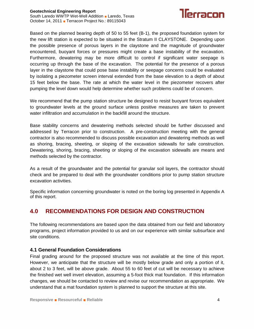
Based on the planned bearing depth of 50 to 55 feet (B-1), the proposed foundation system for
the new lift station is expected to be situated in the Stratum II CLAYSTONE. Depending upon
the possible presence of porous layers in the claystone and the magnitude of groundwater
encountered, buoyant forces or pressures might create a base instability of the excavation.
Furthermore, dewatering may be more difficult to control if significant water seepage is
occurring up through the base of the excavation. The potential for the presence of a porous
layer in the claystone that could pose base instability or seepage concerns could be evaluated
by isolating a piezometer screen interval extended from the base elevation to a depth of about
15 feet below the base. The rate at which the water level in the piezometer recovers after
pumping the level down would help determine whether such problems could be of concern.
We recommend that the pump station structure be designed to resist buoyant forces equivalent
to groundwater levels at the ground surface unless positive measures are taken to prevent
water infiltration and accumulation in the backfill around the structure.
Base stability concerns and dewatering methods selected should be further discussed and
addressed by Terracon prior to construction. A pre-construction meeting with the general
contractor is also recommended to discuss possible excavation and dewatering methods as well
as shoring, bracing, sheeting, or sloping of the excavation sidewalls for safe construction.
Dewatering, shoring, bracing, sheeting or sloping of the excavation sidewalls are means and
methods selected by the contractor.
As a result of the groundwater and the potential for granular soil layers, the contractor should
check and be prepared to deal with the groundwater conditions prior to pump station structure
excavation activities.
Specific information concerning groundwater is noted on the boring log presented in Appendix A of this report.
4.0 RECOMMENDATIONS FOR DESIGN AND CONSTRUCTION
The following recommendations are based upon the data obtained from our field and laboratory
programs, project information provided to us and on our experience with similar subsurface and
site conditions.
4.1 General Foundation Considerations
Final grading around for the proposed structure was not available at the time of this report.
However, we anticipate that the structure will be mostly below grade and only a portion of it,
about 2 to 3 feet, will be above grade. About 55 to 60 feet of cut will be necessary to achieve
the finished wet well invert elevation, assuming a 5-foot thick mat foundation. If this information
changes, we should be contacted to review and revise our recommendation as appropriate. We
understand that a mat foundation system is planned to support the structure at this site.
Geotechnical Engineering Report South Laredo WWTP Wet-Well Addition ■ Laredo, Texas October 14, 2011 ■ Terracon Project No.: 89115043
Responsive ■ Resourceful ■ Reliable 5
The foundation type being considered to provide support for the planned structure must satisfy
several completely independent engineering criteria with respect to the subsurface conditions
encountered at the site. One criterion is the foundation system must be designed with an
appropriate factor of safety to reduce the possibility of a bearing capacity failure of the soils
underlying the foundation when subjected to axial and lateral load conditions. The other
criterion is movement of the foundation system due to compression (consolidation) or expansion
(swell) of the underlying soils must be within tolerable limits for the structure. In addition to the
criteria affecting the performance of the foundations, consideration must also be given to the
effects of lateral earth pressures and hydrostatic pressures that may develop on the buried
portion of the structure.
The suitability and performance of a soil supported foundation for a structure depends on many
factors including the magnitude of soil movement expected, the type of structure, the intended
use of the structure, the construction methods available to stabilize the soils, and our
understanding of the owner’s expectations of the completed structure's performance. Based on
the soil data a mat foundation is considered appropriate for support the anticipated wet-well
structure. Recommendations for a mat foundation are provided in this report. A mat foundation
system may be used at this site provided the bearing surface and foundation are designed and
constructed as recommended in this report.
4.2 Shoring Methods
The primary issue in design and construction of the wet well structure at this site is the selected
method of excavation and shoring. A sloped, open-cut excavation would not be considered
feasible at this site due to the resulting size of the excavation and the presence of adjacent
structures. A vertical shoring system is therefore expected to be required and may consist of a
variety of methods, including, but not limited to:
1. Circular secant or tangent pile wall system.
2. Designing the wet well wall structure with a beveled bottom “cutting edge”, constructing
segments at grade and then internally excavating so that the structure is caused to sink
progressively, in a controlled manner, into the ground as a self-braced caisson.
3. Opting to install multiple wet wells of a diameter that can be drilled with a large diameter
auger (up to ~ 14 feet) into the claystone stratum and stabilizing the excavation with
slurry drilling techniques. This would require lowering pre-fabricated wet well structures
into slurry-filled holes followed by tremmie placement of a wet well bottom/rock socket
concrete mass that is adequate for foundation support and uplift resistance.
4. Tied-back or internally braced sheet pile or soldier pile and lagging system.
5. Progressively installed soil-nailed wall with a reinforced grouted face.
For option No.1, the secant piles could be advanced to the full structure depth and the internal
soils and claystone excavated with a clam shell. The internal secant pile wall surface could be
cleaned and used as the external form for the wet well wall. The secant pile wall would be
designed to carry full lateral soil loads, removing that load from the wet well wall design. The

Geotechnical Engineering Report South Laredo WWTP Wet-Well Addition ■ Laredo, Texas October 14, 2011 ■ Terracon Project No.: 89115043
Responsive ■ Resourceful ■ Reliable 6
secant pile system would also develop large uplift resistance equal to the weight of the secant
piles plus an allowable uplift average skin friction of 1,000 psf times the exterior secant pile wall
surface area. This should minimize the bottom slab thickness required to resist buoyant uplift
forces.
For option No.2, enabling penetration of the caisson into the claystone is expected to pose
potential problems. It would technically be feasible to pre-drill the claystone with a circle of
secant pile excavations backfilled with sand. However, the cost of the drilling would likely
approach the cost of installing an actual secant pile shoring system. An average side friction of
750 psf could be assumed for uplift resistance of a caisson installed in non-pre-drilled soils. If
the perimeter soils are pre-drilled and backfilled with sand, the average side friction assumed for
uplift resistance should be reduced to 300 psf.
Options No.4 and 5 may or may not engage uplift resistance against the shoring or allow use of
the shoring as an exterior wall form.
4.3 Earthwork
The following presents recommendations for site preparation, structure pad preparation and
placement of engineered fills on the project. The recommendations presented for design and
construction of earth supported elements including foundations and slabs are contingent upon
following the recommendations outlined in this section.
Earthwork on the project should be observed and evaluated by Terracon. The evaluation of
earthwork should include observation and testing of engineered fill, mat subgrade preparation,
foundation bearing soils, and other geotechnical conditions exposed during the construction of
the project.
4.3.1 General Site Preparation
If formation of a stabilized working pad is desired, construction areas around the wet well should
be stripped of vegetation and any deleterious material. After site stripping, the exposed
subgrade should be proofrolled with appropriate construction equipment weighing at least 20
tons. The purpose of this recommendation is to check the subgrade for weak, loose, or soft
areas prior to fill placement and compaction of a stabilized working surface, such as crushed
limestone. This operation should be observed and evaluated by Terracon’s qualified
geotechnical personnel experienced in earthwork operations.
If weak, loose, or soft areas are evidenced during proofrolling operations, the soil in the subject
area should be removed to expose competent subgrade soils in both horizontal and vertical
limits. The excavated soils provided they are not contaminated with deleterious materials, or
clean imported fill soils can be used to restore grade at these isolated areas. Any imported fill
should meet the requirements for select fill as presented in the “Fill Materials and Placement”
section of this report.

Geotechnical Engineering Report South Laredo WWTP Wet-Well Addition ■ Laredo, Texas October 14, 2011 ■ Terracon Project No.: 89115043
Responsive ■ Resourceful ■ Reliable 7
The resulting subgrade in cut areas should be scarified to a depth of 8 inches; moisture
conditioned, and compacted to the requirements given in this report. Fill and backfill soils
should be placed; moisture conditioned, and compacted as noted in this report. Soils within
structure area should not be allowed to dry out or become excessively wet after compaction is
completed. Placement and compaction of soil is discussed below:
Structure Area: Refer to the “Fill Materials and Placement” section of this
report.
General and Common Areas (not requiring structural support): Compact to at
least 95 percent of the maximum dry density as evaluated by ASTM D 698
(Standard Compaction) at compaction moisture contents between -2 and +3
percentage points of optimum moisture content.
4.3.2 Mat Subgrade Preparation
We understand that the mat subgrade will be about 50 to 55 feet below grade. Various shoring
options were discussed in the “Shoring Methods” section of this report.
For options No.1, 2, 4 and 5, typical downhole excavation methods are likely to leave a
somewhat uneven surface in the claystone bearing surface. The bearing surface should be
cleaned of all loose materials and observed by a Terracon representative. A leveling course of
poured concrete or compacted clean crushed stone should then be placed to design mat
bearing elevation. Compaction of crushed stone should be as described later in this section of
the report. Due to the presence of highly cemented claystone at the site, rock excavation
equipment will be required.
If the wet well foundation is to be placed in the dry, the bearing surface should be formed with a
slight slope to create an internal sump for seepage water collection and removal. If water in
excess of 2 inches accumulates at the bottom of the excavation, it should be pumped out prior
to concrete placement. Under no circumstances should water be allowed to adversely affect the
quality of the bearing surface.
Backfill around the structure, if required, should consist of select fill soils. Backfill soils should
be compacted to at least 100 percent of the maximum dry density as evaluated by ASTM D 698
(Standard Compaction) at moisture contents between -2 and +3 percentage points of optimum
moisture content. The backfill should be placed in thin, loose lifts not to exceed 8 inches, with
compacted thickness not to exceed 6 inches.
Geotechnical Engineering Report South Laredo WWTP Wet-Well Addition ■ Laredo, Texas October 14, 2011 ■ Terracon Project No.: 89115043
Responsive ■ Resourceful ■ Reliable 8
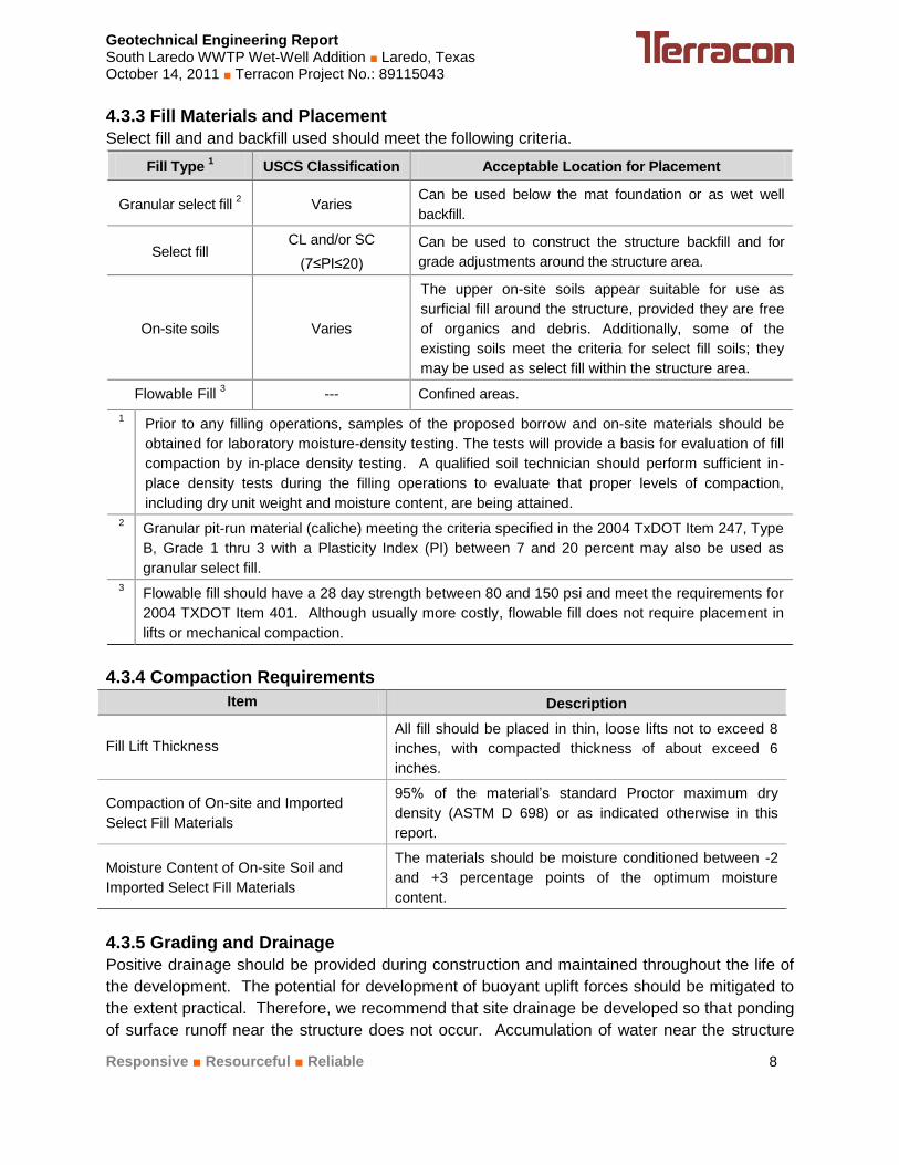
4.3.3 Fill Materials and Placement
Select fill and and backfill used should meet the following criteria.
Fill Type 1 USCS Classification Acceptable Location for Placement
Granular select fill 2 Varies
Can be used below the mat foundation or as wet well
backfill.
Select fill CL and/or SC
(7≤PI≤20)
Can be used to construct the structure backfill and for
grade adjustments around the structure area.
On-site soils Varies
The upper on-site soils appear suitable for use as
surficial fill around the structure, provided they are free
of organics and debris. Additionally, some of the
existing soils meet the criteria for select fill soils; they
may be used as select fill within the structure area.
Flowable Fill 3 --- Confined areas.
1 Prior to any filling operations, samples of the proposed borrow and on-site materials should be
obtained for laboratory moisture-density testing. The tests will provide a basis for evaluation of fill
compaction by in-place density testing. A qualified soil technician should perform sufficient in-
place density tests during the filling operations to evaluate that proper levels of compaction,
including dry unit weight and moisture content, are being attained.
2 Granular pit-run material (caliche) meeting the criteria specified in the 2004 TxDOT Item 247, Type
B, Grade 1 thru 3 with a Plasticity Index (PI) between 7 and 20 percent may also be used as
granular select fill.
3 Flowable fill should have a 28 day strength between 80 and 150 psi and meet the requirements for
2004 TXDOT Item 401. Although usually more costly, flowable fill does not require placement in
lifts or mechanical compaction.
4.3.4 Compaction Requirements
Item Description
Fill Lift Thickness
All fill should be placed in thin, loose lifts not to exceed 8
inches, with compacted thickness of about exceed 6
inches.
Compaction of On-site and Imported
Select Fill Materials
95% of the material’s standard Proctor maximum dry
density (ASTM D 698) or as indicated otherwise in this
report.
Moisture Content of On-site Soil and
Imported Select Fill Materials
The materials should be moisture conditioned between -2
and +3 percentage points of the optimum moisture
content.
4.3.5 Grading and Drainage
Positive drainage should be provided during construction and maintained throughout the life of
the development. The potential for development of buoyant uplift forces should be mitigated to
the extent practical. Therefore, we recommend that site drainage be developed so that ponding
of surface runoff near the structure does not occur. Accumulation of water near the structure

Geotechnical Engineering Report South Laredo WWTP Wet-Well Addition ■ Laredo, Texas October 14, 2011 ■ Terracon Project No.: 89115043
Responsive ■ Resourceful ■ Reliable 9
may cause significant moisture variations in the soils adjacent to the wet-well walls, thus
increasing the potential for structural distress. Special care should be taken such that
underground utilities do not develop leaks with time.
4.3.6 Construction Considerations
It is anticipated that shallow excavations for the proposed construction can be accomplished
with conventional earthmoving equipment. Rock excavation equipment and methods will be
required for excavations extending into the claystone.
Based upon the subsurface conditions determined from the geotechnical exploration, near
surface subgrade soils exposed during construction are anticipated to be relatively unstable.
The stability of the subgrade may be affected by precipitation, repetitive construction traffic or
other factors. If unstable conditions develop, workability may be improved by scarifying and
drying. Overexcavation of wet zones and replacement with granular materials may be
necessary. Lightweight excavation equipment may be required to reduce subgrade pumping.
The contractor is responsible for designing and constructing stable, temporary excavations as
required to maintain the stability of both the excavation sides and bottom. Excavations should
be sloped or shored as required for safety following local and federal regulations, including
current OSHA excavation and trench safety standards.
4.4 Foundations
We understand that a mat foundation system will support the structural loads of the proposed
wet-well structure. Recommendations for this type of foundation system are provided in the
following sections, along with other geotechnical considerations for this project.
4.5 Mat Foundation
The mat should be analyzed using a soil-structure interaction program to identify areas of high
contact stresses, excessive movements and large moments. If a Winkler-type subgrade
modulus model is utilized to model the mat response to load, a subgrade modulus (k) of 100
pounds per cubic inch (pci) can be utilized. Contact stresses should be distributed so that yield
does not occur. The indicated bearing pressure includes a factor of safety against a bearing
capacity failure of at least 3. A value of 0.50 may be used as the ultimate coefficient of friction
between the mat and underlying soil.
If the structure being supported is subjected to uplift loading due to buoyancy or other induced
loads, an over-sized mat, extending beyond the wet well walls would provide more resistance to
uplift since the weight of the soil overlying the mat would also be included in the uplift resistance
computations. Therefore, in addition to the weight of the foundation and structure, the soil
directly overlying the foundation can be considered. A soil unit weight of 100 pounds per cubic
foot (pcf) may be assumed for the on-site soils placed above the footing, provided the fill is
properly compacted. This value should be limited to an allowable maximum passive upward
bearing pressure of 4,000 psf for properly compacted select fill.

Geotechnical Engineering Report South Laredo WWTP Wet-Well Addition ■ Laredo, Texas October 14, 2011 ■ Terracon Project No.: 89115043
Responsive ■ Resourceful ■ Reliable 10
Post construction settlements for the mat foundation designed for the indicated contact pressure
should be less than 1 inch, with differential settlements between the center and edge of the mat
foundation on the order of ½ to ¾ of an inch assuming proper construction. All piping leading to
the structure should be desiged with flexible connections to reduce potential damage due to
differential movements between the structure and the piping.
The mat may bear on a claystone subgrade prepared as recommended as shown below:
Bearing Stratum
Net Allowable End
Bearing Pressure, psf 1
Total Load Dead Load
Undisturbed Claystone 7,500 5,000 1
These bearing pressures include factors of safety of approximately 2 and 3 respectively.
4.5.1 Buoyant Uplift
The wet-well structure should be designed to withstand buoyant uplift forces. The level of
groundwater level recorded at the time of our field investigation was about 43.5 to 46 feet deep.
However, if water infiltrates and accumulates in the backfill around the structure, buoyancy
forces can develop to whatever height the water rises. We recommend that the wet-well
structure be designed to resist buoyant forces equivalent to groundwater levels at the ground
surface unless positive measures are taken to prevent water infiltration and accumulation in the
backfill around the structure.
4.6 Lateral Earth Pressures for Below Grade Structures
The design lateral earth pressure for a 30-foot diameter circular structure could be calculated as
an equivalent fluid pressure using unit weights of 80 pcf from the ground surface to a depth of
15 feet (0 to 1,200 psf) and then increasing at 12 pcf from 15 feet to a depth of 60 feet (1200 to
1,750 psf).
Depending on the type of shoring system used, the wet-well may or may not require external
backfill materials. The pressure exerted by a “veneer” layer of select backfill will be dependent
on the section thickness and material type. We should be consulted to evaluate lateral
pressures from external fill sections, if required.
If the ground surface surrounding the well is to remain open to the elements, then a protective
cover of at least 24-inches should be placed over the granular backfill to reduce surface run-off
infiltration into the backfill materials. The protective cover should consist of relatively impervious
compacted clayey soils (CL or CH) and be sloped to drain away from the structure. The on-site
sandy lean clay or lean clay with sand can be used to construct the protective cover. This
clayey soils cover should be moisture conditioned between optimum and +4 percentage points
of the optimum moisture content. The clayey soils should then be compacted to at least 95

Geotechnical Engineering Report South Laredo WWTP Wet-Well Addition ■ Laredo, Texas October 14, 2011 ■ Terracon Project No.: 89115043
Responsive ■ Resourceful ■ Reliable 11
percent of the maximum dry density determined in accordance with ASTM D 698. The clayey
soils should be placed in thin, loose lifts not to exceed 8 inches, with compacted thickness not to
exceed 6 inches.
4.7 Seismic Considerations
Description Value
2009 International Building Code Site Classification (IBC) 1 D
2
Site Latitude (wet well center) 27.44483°
Site Longitude (wet well center) -99.49250°
Maximum Considered Earthquake 0.2 second Spectral (SS) Acceleration 0.066g
Maximum Considered Earthquake 1.0 second Spectral Acceleration (S1) 0.017g
1 The site class definition was determined using SPT N-values in conjunction with Table 1613.5.2 in the 2009
IBC. The Spectral Acceleration values were determined using publicly available information provided on the
United States Geological Survey (USGS) website. The above criteria can be used to determine the Seismic
Design Category using Tables 1613.5.6 (1) and 1613.5.6 (2) in the 2006 IBC.
2 The 2009 International Building Code (IBC) requires a site soil profile determination extending to a depth of 100
feet for seismic site classification. The current scope does not include the required 100 foot soil profile
determination. The boring extended to a maximum depth of 80 feet, and this seismic site class definition
considers that hard soil continues below the maximum depth of the subsurface exploration. Additional exploration
to deeper depths would be required to confirm the conditions below the current depth of exploration.
4.8 Excavations
The comments and suggestions in this section are provided for planning and informational
purposes so that project specifications can be prepared, and to indicate conventional methods
that can be used to achieve the intent of our design recommendations. Details regarding
excavation, dewatering, selection of equipment/machinery, trafficability, project site safety,
shoring and other similar construction techniques that require "means and methods" to
accomplish the work are the sole responsibility of the project contractor. Construction means
and methods selected by the contractor may differ from those described in this report. Any
variations may significantly impact the anticipated behavior of the subsurface conditions during
the construction process.
Ancillary excavations less than 20 feet in depth should meet the requirements presented in the
following “OSHA Guidelines” section of this report. All excavation should follow OSHA, state
and federal standards and guidelines.
4.8.1 Trench Shoring
Most of the soil encountered throughout the site generally consisted of Sandy Lean Clay and
Clay with Sand materials. The soils encountered at this site were low in plasticity and moisture
content. We anticipate that caving of these soils may occur during excavation operations. The
contractor should be prepared to shore the excavation walls during construction. Safety,

Geotechnical Engineering Report South Laredo WWTP Wet-Well Addition ■ Laredo, Texas October 14, 2011 ■ Terracon Project No.: 89115043
Responsive ■ Resourceful ■ Reliable 12
trenching, and shoring are the responsibility of the contractor. The information presented in this
section provides a general guideline for the contractor.
4.8.2 Trenches
We anticipate that the trenches for the pipelines related to the wet-well will extend to depths of
approximately 50 feet below the ground surface. Groundwater was encountered at depths
shallower than the proposed excavations. Groundwater may be present at a shallower depth
after significant amount of rain fall. We anticipate that it may be difficult to effectively dewater
the Sandy Lean Clay and Lean Clay with Sand soils due to the high content of fine material (i.e.
silt and/or clay). Where excavations extend below the groundwater level in these soils, some
sloughing and/or “running” soil conditions could occur as previously discussed in this report.
Shoring will likely be necessary as discussed in the previous section.
4.8.3 Occupational Safety and Health Administration (OSHA) Guidelines
OSHA Safety and Health Standards (29 CFR Part 1926 Revised, 1989) require that all trenches
in excess of 5 feet deep be shored or appropriately sloped unless the trench sidewalls are
comprised of “solid” rock. State of Texas legislation requires that detailed plans and
specifications for trench retention systems meet OSHA standards for a safe construction
environment during utilities installation. Our recommendations are intended for use in
conjunction with OSHA safety regulations and not as a replacement of those regulations. Based
on the laboratory tests results, the soils encountered at this site should be considered as Type B
soils according to OSHA soil classification guidelines. As stated previously, OSHA requires all
soil trenches in excess of 5 feet be shored or appropriately sloped. Currently available and
practiced methods for achieving slope and/or trench wall stability includes sloping, benching,
combinations of sloping and benching, and installation of shoring systems (hydraulic, timber,
etc.). Trench shields may also be considered for use. However, these shields only provide
protection to workers; they are not a means for providing slope or trench wall stability. OSHA
addresses construction slopes in large excavations that are less than 20 feet deep. The table
shown below is a reproduction of the OSHA. The OSHA regulations define short-term as a
period of 24 hours or less.
OSHA Table
Maximum Allowable Slopes, Short-term (24 Hours or Less)
Soil or Rock Type Maximum Allowable Slopes (H:V)
1
for Excavations Less than 20 Feet Deep2
Stable Rock Vertical 90°
Type A ¾ : 1 53°
Type B 1 : 1 45°
Type C 1½ : 1 34°
1 Numbers shown in parentheses next to maximum allowable slopes are angles expressed in degrees from the horizontal. Angles have been rounded off.
2 A short-term maximum allowable slope of ½H:1V (63°) is allowed in excavations in Type A soil that are 12 feet or less in depth. Short-term maximum allowable slopes for excavations greater than 12

Geotechnical Engineering Report South Laredo WWTP Wet-Well Addition ■ Laredo, Texas October 14, 2011 ■ Terracon Project No.: 89115043
Responsive ■ Resourceful ■ Reliable 13
OSHA Table
Maximum Allowable Slopes, Short-term (24 Hours or Less)
Soil or Rock Type Maximum Allowable Slopes (H:V)
1
for Excavations Less than 20 Feet Deep2
feet in depth shall be ¾H:1V (53°).
3 Sloping or benching for excavations greater than 20 feet shall be designed by a licensed professional engineer. The OSHA regulations define short-term as a period of 24 hours or less.
4.9 Other Design/Construction Considerations
If corrosivity is critical to construction, it is recommended that laboratory testing be performed on
soil samples collected from the site.
4.9.1 Concrete Considerations
Additional testing on selected soil samples from the project site should be required to determine
chlorides, PH and sulfate content. The sulfate levels in the soil should be compared to the
criteria presented in ACI 318 Table 4.3.1. Provisions should be made to address the potential
sulfate attack when designing the concrete structures. However, Type II Portland Cement or
any other approved by ACI should be used to resist sulfate attack. Recommendations for
water-cement ratio and minimum design compressive strength are also provided by the above
mentioned ACI table.
Additionally, a source of aggregates that is known to be reactive with alkalis shall not be used in
the concrete. If a reactive aggregate must be used, measures should be taken to mitigate the
chances for alkali silica reaction. One method to achieve this is the use of a lithium nitrate
admixture along with a low alkali cement.

Geotechnical Engineering Report South Laredo WWTP Wet-Well Addition ■ Laredo, Texas October 14, 2011 ■ Terracon Project No.: 89115043
Responsive ■ Resourceful ■ Reliable 14
5.0 GENERAL COMMENTS Terracon should be retained to review the final design plans and specifications so comments
can be made regarding interpretation and implementation of our geotechnical recommendations
in the design and specifications. Terracon also should be retained to provide observation and
testing services during grading, excavation, foundation construction and other earth-related
construction phases of the project.
The analysis and recommendations presented in this report are based upon the data obtained
from the boring performed at the indicated location and from other information discussed in this
report. This report does not reflect variations that may occur at the boring, or due to the
modifying effects of weather. The nature and extent of such variations may not become evident
until during or after construction. If variations appear, we should be immediately notified so that
further evaluation and supplemental recommendations can be provided.
The scope of services for this project does not include either specifically or by implication any
environmental or biological (e.g., mold, fungi, bacteria) assessment of the site or identification or
prevention of pollutants, hazardous materials or conditions. If the owner is concerned about the
potential for such contamination or pollution, other studies should be undertaken.
This report has been prepared for the exclusive use of our client for specific application to the
project discussed and has been prepared in accordance with generally accepted geotechnical
engineering practices. No warranties, either express or implied, are intended or made. Site
safety, excavation support, and dewatering requirements are the responsibility of others. In the
event that changes in the nature, design, or location of the project as outlined in this report are
planned, the conclusions and recommendations contained in this report shall not be considered
valid unless Terracon reviews the changes and either verifies or modifies the conclusions of this
report in writing.

Geotechnical Engineering Report South Laredo WWTP Wet-Well Addition ■ Laredo, Texas October 14, 2011 ■ Terracon Project No.: 89115043
Responsive ■ Resourceful ■ Reliable Table 1
TABLE 1
SOIL PROPERTIES SOUTH LAREDO WWTP WET-WELL ADDITION
RIVER FRONT STREET
LAREDO, TEXAS
TERRACON PROJECT NO. 89115043
Layer Depth, ft. Cohesion,
psf
Total Unit
Weigth, pcf
Effective
Unit Weight,
pcf
Friction
Angle,
degrees
In-Situ
Modulus E’n
,psi
1 0 – 5 1,000 115 115 --- 450
2 5 – 10 2,000 115 115 --- 750
3 10 – 20 3,000 120 120 --- 1,500
4 20 – 43 3,000 120 120 --- 1,500
5 43 – 50 4,000 120 58 --- 2,000
6 50 – 80 5,000 125 63 --- 2,000
1. Design depth to groundwater is assumed to be at 43 feet.

Geotechnical Engineering Report South Laredo WWTP Wet-Well Addition ■ Laredo, Texas October 14, 2011 ■ Terracon Project No.: 89115043
Responsive ■ Resourceful ■ Reliable
APPENDIX A
FIELD EXPLORATION

Geotechnical Engineering Report South Laredo WWTP Wet-Well Addition ■ Laredo, Texas October 14, 2011 ■ Terracon Project No.: 89115043
Responsive ■ Resourceful ■ Reliable Exhibit A-1
Field Exploration Description
Terracon personnel used the site plan provided by the client to identify the bore location in the
field. A copy of the Bore Location Plan indicating the approximate boring location is included in
Appendix A. The boring location was staked by others prior to our arriving at the site.
A truck-mounted, rotary drill rig equipped with continuous flight augers was used to advance the
borehole. Soil samples were obtained by the split-barrel sampling procedure. In the split-barrel
sampling procedure, a standard 2-inch O.D. split-barrel sampling spoon is driven into the
ground with a 140-pound hammer falling a height of 30 inches. The number of blows required to
advance the sampling spoon the last 12 inches of a normal 18-inch penetration is recorded as
the standard penetration resistance value. These values are indicated on the boring log at the
depth of occurrence. The samples were sealed and transported to our laboratory for testing and
classification.
Our field representative prepared the field log as part of the drilling operations. The field log
included visual classifications of the materials encountered during drilling and our field
representative interpretation of the subsurface conditions between samples. The boring log
included with this report represent the engineer’s interpretation of the field log and include
modifications based on visual observations and testing of the samples in the laboratory.
The scope of services for our geotechnical engineering services does not include addressing
any environmental issues pertinent to the site.

i i i
1i I i i I
i
I i I i i i i
,\ i I!
I
i I ; i I ; I
; ; ! I
! I
f I ; i I ; ; ; i ;
I I
\
! m ~ l
!
\
PROJECT SITE l
Project Mngr: MMR
Project No. 89115043
Drawn By: Scale: LS(90) N.T.S.
Checked By: File No. 89115043 EAM
Approved Br. Date:
EAM 09-20-11
n :r: m /./1
if 0 O ~ J~ L RIVEIU RONT ST i
{
llerracon ~ ---Ind 8clenlllla
61 5 GALE STREET, BUILDING B LAREDO, TX 78041
PH. (956) 729,1100 FAX. (956) 791-1071
LJ I
l
N
II
SITE LOCATION PLAN EXHIBIT
Wet Well Addition South Laredo WWTP
Laredo, Texas A-2

I "
j i "
r "
I i ><
I i ~Fenceline X
I i i i i i i i i "
I i i
LEGEND:
-0 . Af'f'IIOJCIMAlE BOIE LOCAllON
Transfonner 1 c~~,,~; Tank , ~ MCC
J,_, ""' _.,O Building
Sewer Manhole_/
Pump Station
wi1h Cone. Apron ., ·.-,,'>:;: Sewer Manhole ~
'{ ss 1:. ·:::~ - •;:~.
N ProjectMngr:
t Drawn By:
Checked By.
Approved By:
MMR
LS(90)
EAM
EAM
~ [ >
·~
•>
.di
,. " LJ
CJ
""'ii
•->
.J'
J
iJ ~
Sewer Manhole~
"®
Gravel Drive and Parking
I I I
\ \_: Concrete Fooling
\_ Partially Oemolishecl Bar Screens
IT~ Co«c,ts FoOl'll
?artially Demolished P ur,-? Station
.. ..
Project No. 89115043 llerracon
BORE LOCATION PLAN Scale:
N.T.S. Wet Well Addition Fi~No.
89115043 ~ --.111c18clenlllll South Laredo WWTP Date: 61 5 GALE STREET, BUILDING B LAREDO, TX 78041 Laredo, Texas
09-20-11 PH. (956) 729-1100 FAX. (956) 791-1071
D
K
EXHIBIT
A-3

10.0
STRATUM ISANDY LEAN CLAY; brown, stiff to hard,silty sand with gravel to 2 feet.
- with SANDY SILT (ML) layers at 8.5feet.STRATUM IALEAN CLAY with SAND; brown, stiff tohard
- with LEAN CLAY (CL) layers at 33.5feet.
6
9
NP
13
65
78
89
SS
SS
SS
SS
SS
SS
SS
SS
SS
SS
SS
19
17
19
N=41
N=31
N=25
N=14
N=12
N=10
N=10
N=19
N=17
N=26
N=37
3
6
6
6
4
9
11
12
16
18
18
25
26
32
CL
CL
Approx. Surface Elevation: Existing GradeGra
phic
Log
Continued Next Page
DESCRIPTION
CDMSan Antonio,, Texas
46 ft
See Bore Location Plan
Thi
s Lo
g is
not
val
id if
sep
erat
ed fr
om o
rigi
nal r
epor
t.
EXHIBIT
A-4PROJECT NUMBER
89115043
LOG OF BORING NO. B-1
BORINGLOCATION:
Remarks - Dry augered to 50 feet, wet rotary techniques thereafter. Free water wasencountered at 46 feet. The borehole was backfilled with cuttings after the groundwaterobservations were completed.NP: Non Plastic140 lbs. SPT manual hammer.
STRATIFICATION LINES REPRESENT APPROXIMATEBOUNDARIES BETWEEN SOIL TYPES. IN SITU, THETRANSITION BETWEEN STRATA MAY BE MOREGRADUAL.
CLIENT:
43.5 ft
WATER LEVEL OBSERVATIONS Page 1 of 2DATE DRILLED
8/29/2011
US
CS
SY
MB
OL
PLA
ST
ICIT
Y I
ND
EX
CO
MP
RE
SS
IVE
ST
RE
NG
TH
, T
SF
DE
PT
H,
FE
ET
SITE:
PROJECT:
FA
ILU
RE
ST
RA
IN,
%
CO
NF
ININ
GP
RE
SS
UR
E,
PS
I
TESTS
DR
Y D
EN
SIT
Y,
PC
F
MIN
US
#20
0S
IEV
E,
%
Laredo, TexasSAMPLES
5
10
15
20
25
30
35
40
PLA
ST
IC L
IMIT
, %
South Laredo WWTP Wet-Well Addition
LIQ
UID
LIM
IT,
%
River Front Street
TY
PE
MO
IST
UR
EC
ON
TE
NT
, %
N:
BLO
WS
/FT
P:
TO
NS
/SQ
FT
T:
TO
NS
/SQ
FT

48.5
80.0
STRATUM IALEAN CLAY with SAND; brown, stiff tohard
- with ferrous stains at 43.5 feet.
STRATUM IICLAYSTONE; dark bluish gray, hard,highly cemented
Boring Terminated at about 80 feet.
14
5
10
21
30
SS
SS
SS
SS
SS
SS
SS
SS
20
23
23
16
N=19
N=ref/1"
N=ref/2"
N=ref/2"
N=ref/4"
N=ref/4"
N=ref/3"
N=ref/3"
23
17
31
20
28
31
19
34
28
33
37
Approx. Surface Elevation: Existing GradeGra
phic
Log DESCRIPTION
CDMSan Antonio,, Texas
46 ft
See Bore Location Plan
Thi
s Lo
g is
not
val
id if
sep
erat
ed fr
om o
rigi
nal r
epor
t.
EXHIBIT
A-4PROJECT NUMBER
89115043
LOG OF BORING NO. B-1
BORINGLOCATION:
Remarks - Dry augered to 50 feet, wet rotary techniques thereafter. Free water wasencountered at 46 feet. The borehole was backfilled with cuttings after the groundwaterobservations were completed.NP: Non Plastic140 lbs. SPT manual hammer.
STRATIFICATION LINES REPRESENT APPROXIMATEBOUNDARIES BETWEEN SOIL TYPES. IN SITU, THETRANSITION BETWEEN STRATA MAY BE MOREGRADUAL.
CLIENT:
43.5 ft
WATER LEVEL OBSERVATIONS Page 2 of 2DATE DRILLED
8/29/2011
US
CS
SY
MB
OL
PLA
ST
ICIT
Y I
ND
EX
CO
MP
RE
SS
IVE
ST
RE
NG
TH
, T
SF
DE
PT
H,
FE
ET
SITE:
PROJECT:
FA
ILU
RE
ST
RA
IN,
%
CO
NF
ININ
GP
RE
SS
UR
E,
PS
I
TESTS
DR
Y D
EN
SIT
Y,
PC
F
MIN
US
#20
0S
IEV
E,
%
Laredo, TexasSAMPLES
45
50
55
60
65
70
75
80
PLA
ST
IC L
IMIT
, %
South Laredo WWTP Wet-Well Addition
LIQ
UID
LIM
IT,
%
River Front Street
TY
PE
MO
IST
UR
EC
ON
TE
NT
, %
N:
BLO
WS
/FT
P:
TO
NS
/SQ
FT
T:
TO
NS
/SQ
FT

Geotechnical Engineering Report South Laredo WWTP Wet-Well Addition ■ Laredo, Texas October 14, 2011 ■ Terracon Project No.: 89115043
Responsive ■ Resourceful ■ Reliable
APPENDIX B
LABORATORY TESTING

Geotechnical Engineering Report South Laredo WWTP Wet-Well Addition ■ Laredo, Texas October 14, 2011 ■ Terracon Project No.: 89115043
Responsive ■ Resourceful ■ Reliable Exhibit B-1
Laboratory Testing
Samples retrieved during the field exploration were taken to the laboratory for further
observation by the project geotechnical engineer and were classified in accordance with the
Unified Soil Classification System (USCS) described in this Appendix. At that time, the field
descriptions were confirmed or modified as necessary and an applicable laboratory testing
program was formulated to determine engineering properties of the subsurface materials.
Laboratory tests were conducted on selected soil samples and the test results are presented in
this appendix. The laboratory test results were used for the geotechnical engineering analyses,
and the development of foundation and earthwork recommendations. Laboratory tests were
performed in general accordance with the applicable ASTM, local or other accepted standards.
Selected soil samples obtained from the site were tested for the following engineering
properties:
In-situ Water Content
Atterberg Limits
Amount of Material In-Soil Finer than the No 200 Mesh (75-µm) Sieve
Sample Disposal
All samples were returned to our laboratory. The samples not tested in the laboratory will be
stored for a period of 30 days subsequent to submittal of this report and will be discarded after
this period, unless other arrangements are made prior to the disposal period.
Geotechnical Engineering Report South Laredo WWTP Wet-Well Addition ■ Laredo, Texas October 14, 2011 ■ Terracon Project No.: 89115043
Responsive ■ Resourceful ■ Reliable
APPENDIX C
SUPPORTING DOCUMENTS

Exhibit C-1
GENERAL NOTES
DRILLING & SAMPLING SYMBOLS:
SS: Split Spoon – 1-3/8" I.D., 2" O.D., unless otherwise noted HS: Hollow Stem Auger
ST: Thin-Walled Tube - 2" O.D., unless otherwise noted PA: Power Auger
RS: Ring Sampler - 2.42" I.D., 3" O.D., unless otherwise noted HA: Hand Auger
DB: Diamond Bit Coring - 4", N, B RB: Rock Bit
BS: Bulk Sample or Auger Sample WB: Wash Boring or Mud Rotary
The number of blows required to advance a standard 2-inch O.D. split-spoon sampler (SS) the last 12 inches of the total 18-inch
penetration with a 140-pound hammer falling 30 inches is considered the “Standard Penetration” or “N-value”.
WATER LEVEL MEASUREMENT SYMBOLS:
WL: Water Level WS: While Sampling N/E: Not Encountered
WCI: Wet Cave in WD: While Drilling
DCI: Dry Cave in BCR: Before Casing Removal
AB: After Boring ACR: After Casing Removal
Water levels indicated on the boring logs are the levels measured in the borings at the times indicated. Groundwater levels at other times and other locations across the site could vary. In pervious soils, the indicated levels may reflect the location of groundwater. In low permeability soils, the accurate determination of groundwater levels may not be possible with only short-term observations.
DESCRIPTIVE SOIL CLASSIFICATION: Soil classification is based on the Unified Classification System. Coarse Grained Soils
have more than 50% of their dry weight retained on a #200 sieve; their principal descriptors are: boulders, cobbles, gravel or sand. Fine Grained Soils have less than 50% of their dry weight retained on a #200 sieve; they are principally described as clays if they are plastic, and silts if they are slightly plastic or non-plastic. Major constituents may be added as modifiers and minor constituents may be added according to the relative proportions based on grain size. In addition to gradation, coarse-grained soils are defined on the basis of their in-place relative density and fine-grained soils on the basis of their consistency.
CONSISTENCY OF FINE-GRAINED SOILS RELATIVE DENSITY OF COARSE-GRAINED SOILS
Unconfined
Compressive
Strength, Qu, psf
Standard Penetration or N-value (SS)
Blows/Ft. Consistency
Standard Penetration or N-value (SS)
Blows/Ft.
Ring Sampler (RS) Blows/Ft.
Relative Density
< 500 <2 Very Soft 0 – 3 0-6 Very Loose
500 – 1,000 2-3 Soft 4 – 9 7-18 Loose
1,001 – 2,000 4-6 Medium Stiff 10 – 29 19-58 Medium Dense
2,001 – 4,000 7-12 Stiff 30 – 49 59-98 Dense
4,001 – 8,000 13-26 Very Stiff 50+ 99+ Very Dense
8,000+ 26+ Hard
RELATIVE PROPORTIONS OF SAND AND GRAVEL GRAIN SIZE TERMINOLOGY
Descriptive Term(s) of other
Constituents
Percent of
Dry Weight
Major Component
of Sample Particle Size
Trace < 15 Boulders Over 12 in. (300mm)
With 15 – 29 Cobbles 12 in. to 3 in. (300mm to 75 mm)
Modifier > 30 Gravel 3 in. to #4 sieve (75mm to 4.75 mm)
Sand
Silt or Clay
#4 to #200 sieve (4.75mm to 0.075mm)
Passing #200 Sieve (0.075mm)
RELATIVE PROPORTIONS OF FINES PLASTICITY DESCRIPTION
Descriptive Term(s) of other
Constituents
Percent of
Dry Weight Term
Plasticity
Index
Trace < 5 Non-plastic 0
With 5 – 12 Low 1-10
Modifiers > 12 Medium 11-30
High 30+

Exhibit C-2
UNIFIED SOIL CLASSIFICATION SYSTEM
Criteria for Assigning Group Symbols and Group Names Using Laboratory Tests A
Soil Classification
Group
Symbol Group Name
B
Coarse Grained Soils:
More than 50% retained
on No. 200 sieve
Gravels:
More than 50% of
coarse
fraction retained on
No. 4 sieve
Clean Gravels:
Less than 5% fines C
Cu 4 and 1 Cc 3 E
GW Well-graded gravel F
Cu 4 and/or 1 Cc 3 E
GP Poorly graded gravel F
Gravels with Fines:
More than 12% fines C
Fines classify as ML or MH GM Silty gravel F,G, H
Fines classify as CL or CH GC Clayey gravel F,G,H
Sands:
50% or more of coarse
fraction passes
No. 4 sieve
Clean Sands:
Less than 5% fines D
Cu 6 and 1 Cc 3 E
SW Well-graded sand I
Cu 6 and/or 1 Cc 3 E
SP Poorly graded sand I
Sands with Fines:
More than 12% fines D
Fines classify as ML or MH SM Silty sand G,H,I
Fines Classify as CL or CH SC Clayey sand G,H,I
Fine-Grained Soils:
50% or more passes the
No. 200 sieve
Silts and Clays:
Liquid limit less than 50
Inorganic: PI 7 and plots on or above “A” line
J CL Lean clay
K,L,M
PI 4 or plots below “A” line J ML Silt
K,L,M
Organic: Liquid limit - oven dried
0.75 OL Organic clay
K,L,M,N
Liquid limit - not dried Organic silt K,L,M,O
Silts and Clays:
Liquid limit 50 or more
Inorganic: PI plots on or above “A” line CH Fat clay
K,L,M
PI plots below “A” line MH Elastic Silt K,L,M
Organic: Liquid limit - oven dried
0.75 OH Organic clay
K,L,M,P
Liquid limit - not dried Organic silt K,L,M,Q
Highly organic soils: Primarily organic matter, dark in color, and organic odor PT Peat
A Based on the material passing the 3-in. (75-mm) sieve
B If field sample contained cobbles or boulders, or both, add “with cobbles
or boulders, or both” to group name. C
Gravels with 5 to 12% fines require dual symbols: GW-GM well-graded
gravel with silt, GW-GC well-graded gravel with clay, GP-GM poorly
graded gravel with silt, GP-GC poorly graded gravel with clay. D
Sands with 5 to 12% fines require dual symbols: SW-SM well-graded
sand with silt, SW-SC well-graded sand with clay, SP-SM poorly graded
sand with silt, SP-SC poorly graded sand with clay
E Cu = D60/D10 Cc =
6010
2
30
DxD
)(D
F If soil contains 15% sand, add “with sand” to group name.
G If fines classify as CL-ML, use dual symbol GC-GM, or SC-SM.
H If fines are organic, add “with organic fines” to group name.
I If soil contains 15% gravel, add “with gravel” to group name.
J If Atterberg limits plot in shaded area, soil is a CL-ML, silty clay.
K If soil contains 15 to 29% plus No. 200, add “with sand” or “with
gravel,” whichever is predominant. L
If soil contains 30% plus No. 200 predominantly sand, add “sandy”
to group name. M
If soil contains 30% plus No. 200, predominantly gravel, add
“gravelly” to group name. N
PI 4 and plots on or above “A” line. O
PI 4 or plots below “A” line. P
PI plots on or above “A” line. Q
PI plots below “A” line.