geotechnical engineering report - oklahoma … · geotechnical engineering report ... of piles...
TRANSCRIPT
Geotechnical Engineering Report SH-82 Bridge Over Locust Creek
Craig County, Oklahoma
Project No. STPY-255F (191) EC
Job Piece No. 30308 (06)
April 1, 2015
Terracon Project No. 04155007
Prepared for:
Oklahoma Department of Transportation
Oklahoma City, Oklahoma
Prepared by:
Terracon Consultants, Inc.
Tulsa, Oklahoma
April 1, 2015
Oklahoma Department of Transportation Bridge Division 200 N.E. 21 st Room 3-C9
Oklahoma City, Oklahoma 73105
Attn: Mr. Steve Jacobi, P.E. E: [email protected]
Re: Geotechnical Engineering Report SH-82 Bridge Over Locust Creek Craig County, Oklahoma Project No. STPY-255F (191) EC Job Piece No. 30308 (06) Terracon Project Number: 04155007
Dear Mr. Jacobi:
llerracan
Terracon Consultants, Inc. (Terracon) has completed the geotechnical engineering services for the above referenced project. This study was performed in general accordance with our proposal number P04140709 dated December 23, 2014 and ODOT Engineering Contract EC-1445C, Task Order No. 5. This report presents the findings of the subsurface exploration and provides geotechnical recommendations for the design and construction of bridge foundations as related to the subsurface conditions encountered at the borings.
We appreciate the opportunity to be of service to you on this project. If you have any questions concerning this report, or if we may be of further service, please contact us.
Sincerely, Terracon Consultants, Inc. Cert. of Auth. #CA-4531 exp. 6/30/15
Fernando L. Aponte-Rivera, E.l.T. Staff Geotechnical Engineer
Enclosures Addressee (1 via US Mail and 1 via email)
Terracon Consultants, Inc. 9522 East 4 71h Place, Uni t D Tulsa, Oklahoma 7 4145 P [918] 250 0461 F [918] 250 4570 terracon.com
Geotechnical • Environmental • Construction Materials • Facilities
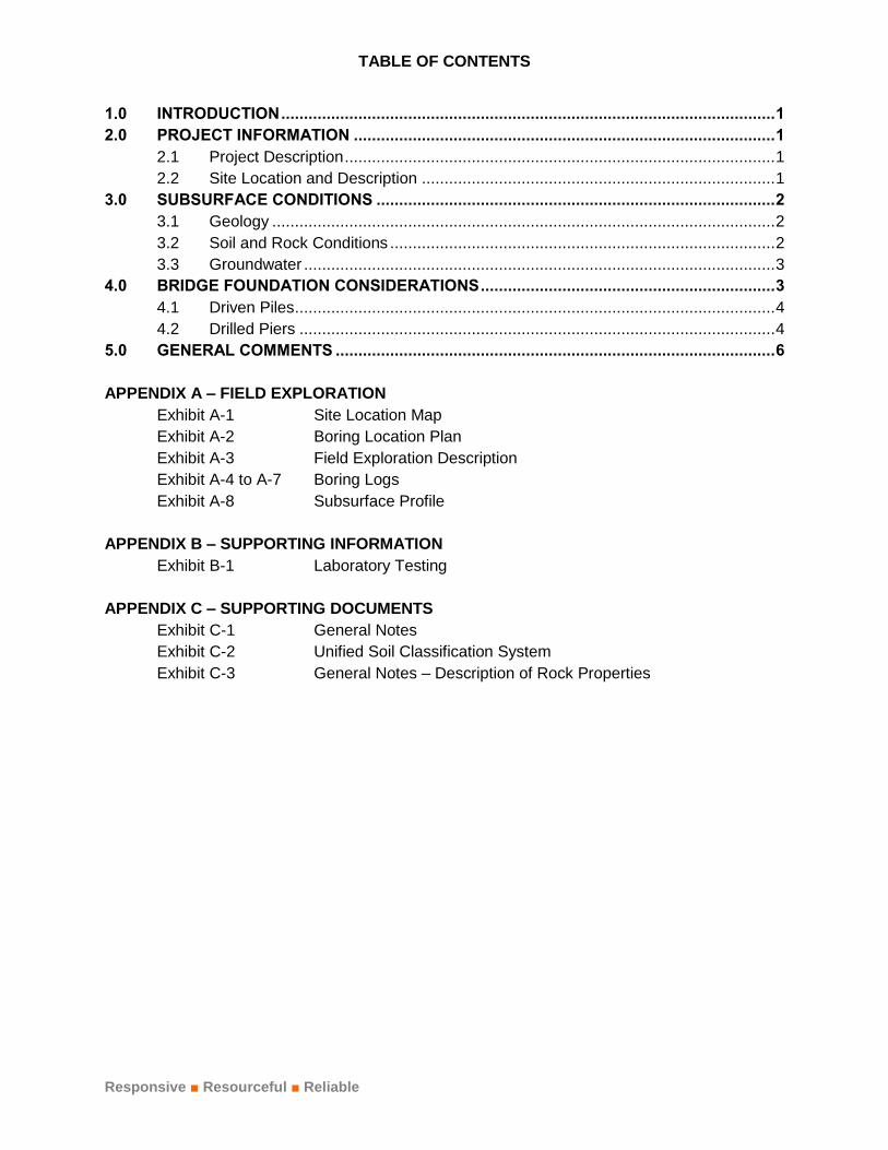
TABLE OF CONTENTS
Responsive ■ Resourceful ■ Reliable
INTRODUCTION ............................................................................................................. 1 1.0
PROJECT INFORMATION ............................................................................................. 1 2.0
2.1 Project Description ............................................................................................... 1
2.2 Site Location and Description .............................................................................. 1
SUBSURFACE CONDITIONS ........................................................................................ 2 3.0
3.1 Geology ............................................................................................................... 2
3.2 Soil and Rock Conditions ..................................................................................... 2
3.3 Groundwater ........................................................................................................ 3
BRIDGE FOUNDATION CONSIDERATIONS ................................................................. 3 4.0
4.1 Driven Piles .......................................................................................................... 4
4.2 Drilled Piers ......................................................................................................... 4
GENERAL COMMENTS ................................................................................................. 6 5.0
APPENDIX A – FIELD EXPLORATION
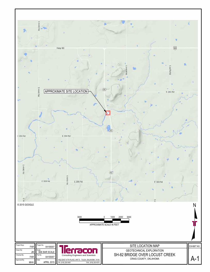
Exhibit A-1 Site Location Map
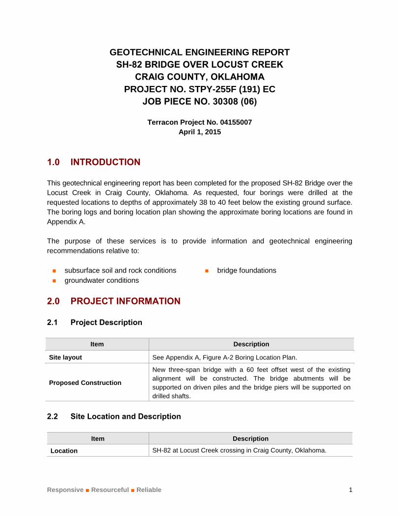
Exhibit A-2 Boring Location Plan
Exhibit A-3 Field Exploration Description
Exhibit A-4 to A-7 Boring Logs
Exhibit A-8 Subsurface Profile
APPENDIX B – SUPPORTING INFORMATION
Exhibit B-1 Laboratory Testing
APPENDIX C – SUPPORTING DOCUMENTS
Exhibit C-1 General Notes
Exhibit C-2 Unified Soil Classification System
Exhibit C-3 General Notes – Description of Rock Properties
Responsive ■ Resourceful ■ Reliable 1
GEOTECHNICAL ENGINEERING REPORT
SH-82 BRIDGE OVER LOCUST CREEK
CRAIG COUNTY, OKLAHOMA
PROJECT NO. STPY-255F (191) EC
JOB PIECE NO. 30308 (06)
Terracon Project No. 04155007
April 1, 2015
INTRODUCTION 1.0
This geotechnical engineering report has been completed for the proposed SH-82 Bridge over the
Locust Creek in Craig County, Oklahoma. As requested, four borings were drilled at the
requested locations to depths of approximately 38 to 40 feet below the existing ground surface.
The boring logs and boring location plan showing the approximate boring locations are found in
Appendix A.
The purpose of these services is to provide information and geotechnical engineering
recommendations relative to:
subsurface soil and rock conditions bridge foundations
groundwater conditions
PROJECT INFORMATION 2.0
2.1 Project Description
Item Description
Site layout See Appendix A, Figure A-2 Boring Location Plan.
Proposed Construction
New three-span bridge with a 60 feet offset west of the existing
alignment will be constructed. The bridge abutments will be
supported on driven piles and the bridge piers will be supported on
drilled shafts.
2.2 Site Location and Description
Item Description
Location SH-82 at Locust Creek crossing in Craig County, Oklahoma.

Geotechnical Engineering Report SH-82 Bridge Over Locust Creek ■ Craig County, Oklahoma April 1, 2015 ■ Terracon Project No. 04155007
Responsive ■ Resourceful ■ Reliable 2
SUBSURFACE CONDITIONS 3.0
3.1 Geology
Based on the results of our borings and information published in the Oklahoma Department of
Transportation manual, “Engineering Classification of Geologic Materials: Division 8”, the site
appears to be underlain the Chester-Meramec Unit. This unit consists of limestone, chert, shale,
sandstone and siltstone, with the lithology of the unit varying locally.
In Craig and Mayes Counties, the limestone thickens to 40 feet locally but generally is about 30
feet thick and contains some green shale stringers. The overlying black shale contains
numerous thin beds of limestone and siltstone.
3.2 Soil and Rock Conditions
The subsurface conditions encountered in the borings are shown on the boring logs and are
briefly described below. The stratification lines shown on the boring logs represent the
approximate boundary between soil and rock types; in-situ, the transition between materials may
be gradual and indistinct. Classification of bedrock materials was made from disturbed samples
and rock cores. Petrographic analysis may reveal other rock types.
Description
Approximate Depth
to Bottom of
Stratum
Material Encountered Consistency/Density
Surface 3 inches Topsoil N/A
Stratum 1 5 to 9 feet Lean clay, lean to fat clay, fat clay Soft to stiff
Stratum 21
8 to 10 feet Sandy lean clay, sandstone
Clay: Medium stiff
Sandstone: Poorly
cemented to well
cemented
Stratum 32
Encountered to
boring termination
depths of 38 to 40
feet
Limestone Hard
1. Sandstone was encountered in borings B-1, B-2 and B-3 at depths of 9, 8.5 and 6 feet,
respectively.
2. Auger refusal was encountered in boring B-3 at 8 feet.
Geotechnical Engineering Report SH-82 Bridge Over Locust Creek ■ Craig County, Oklahoma April 1, 2015 ■ Terracon Project No. 04155007
Responsive ■ Resourceful ■ Reliable 3
Laboratory tests were conducted on selected soil and rock core samples. The test results are
presented on the boring logs in Appendix A.
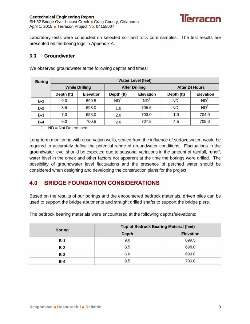
3.3 Groundwater
We observed groundwater at the following depths and times:
Boring Water Level (feet)
While Drilling After Drilling After 24 Hours
Depth (ft) Elevation Depth (ft) Elevation Depth (ft) Elevation
B-1 9.0 699.5 ND1
ND1
ND1
ND1
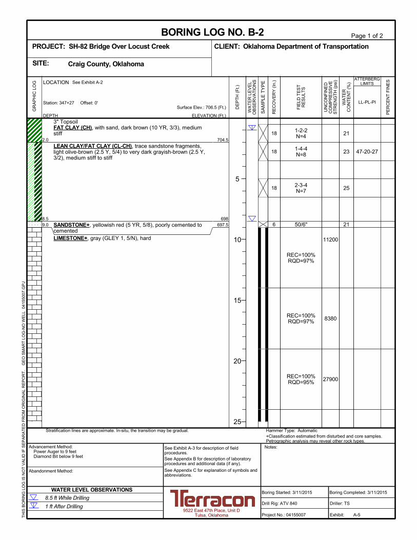
B-2 8.5 698.0 1.0 705.5 ND1
ND1
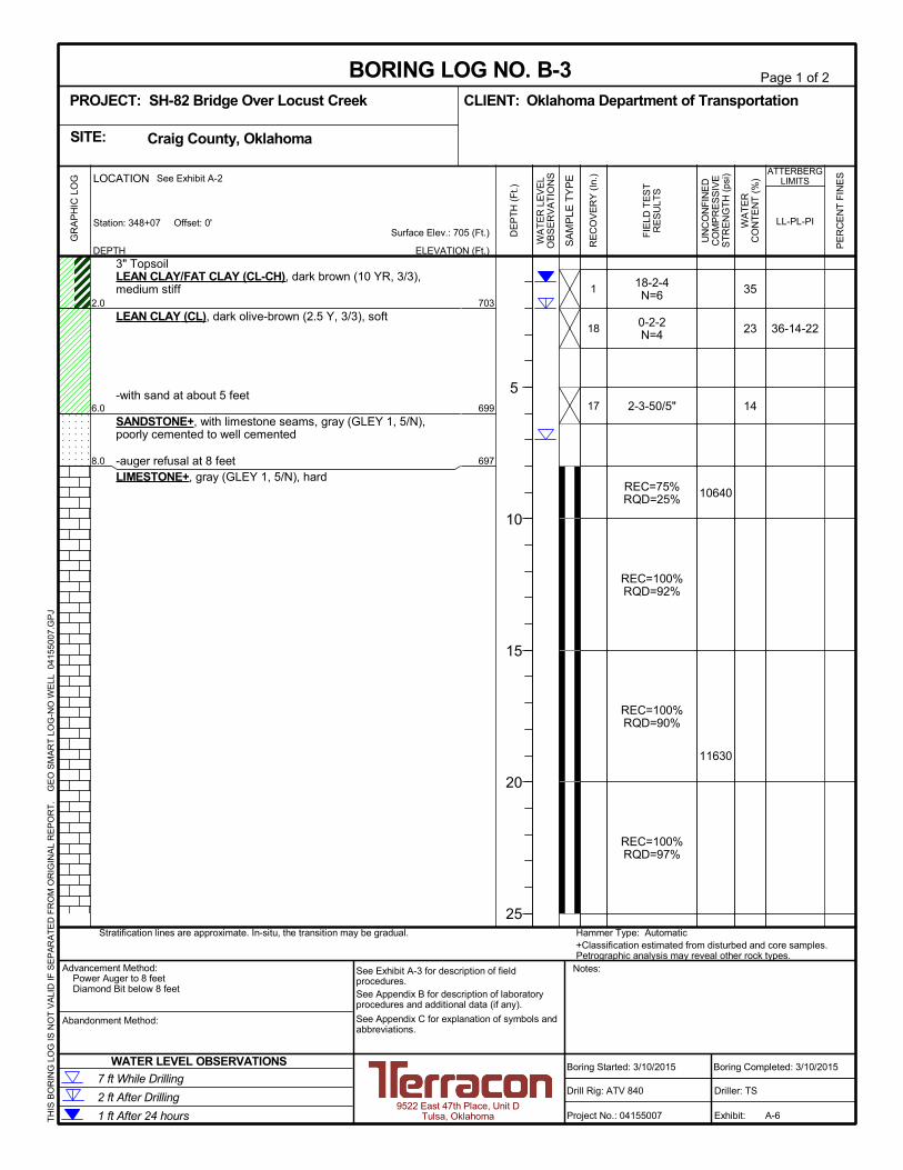
B-3 7.0 698.0 2.0 703.0 1.0 704.0
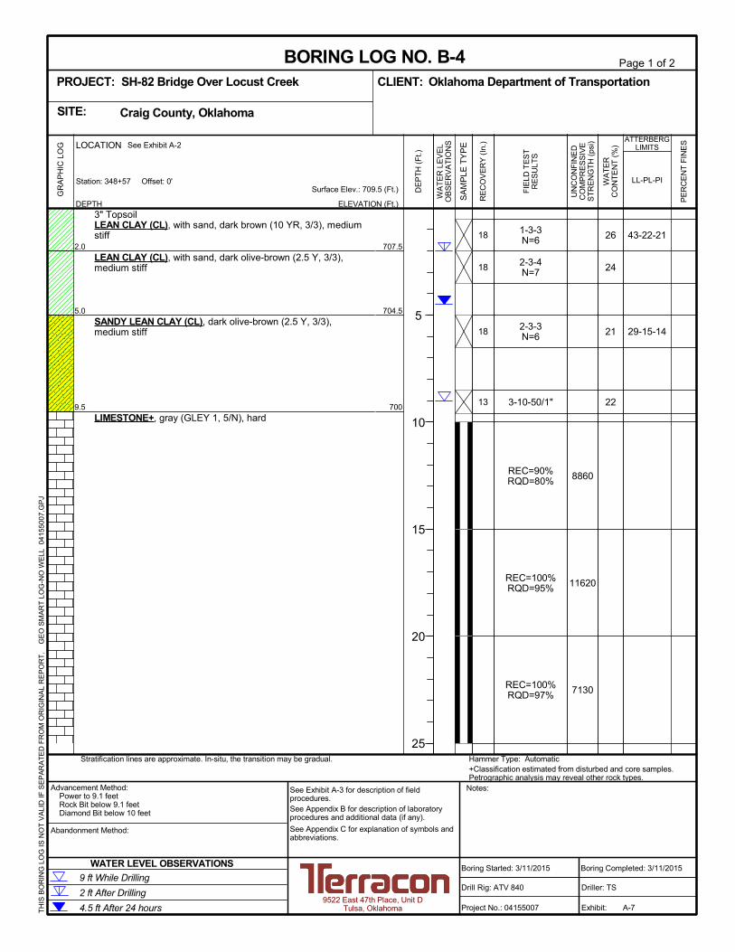
B-4 9.0 700.5 2.0 707.5 4.5 705.0
1. ND = Not Determined
Long-term monitoring with observation wells, sealed from the influence of surface water, would be
required to accurately define the potential range of groundwater conditions. Fluctuations in the
groundwater level should be expected due to seasonal variations in the amount of rainfall, runoff,
water level in the creek and other factors not apparent at the time the borings were drilled. The
possibility of groundwater level fluctuations and the presence of perched water should be
considered when designing and developing the construction plans for the project.
BRIDGE FOUNDATION CONSIDERATIONS 4.0
Based on the results of our borings and the encountered bedrock materials, driven piles can be
used to support the bridge abutments and straight drilled shafts to support the bridge piers.
The bedrock bearing materials were encountered at the following depths/elevations:
Boring Top of Bedrock Bearing Material (feet)
Depth Elevation
B-1 9.0 699.5
B-2 8.5 698.0
B-3 6.0 699.0
B-4 9.5 700.0

Geotechnical Engineering Report SH-82 Bridge Over Locust Creek ■ Craig County, Oklahoma April 1, 2015 ■ Terracon Project No. 04155007
Responsive ■ Resourceful ■ Reliable 4
4.1 Driven Piles
Driven steel HP piles driven to practical refusal in the bedrock can be used to support the
abutments. According to AASHTO’s LRFD Bridge Design Specifications, the nominal resistance
of piles driven to bear on hard rock where pile penetration into the rock formation is minimal is
controlled by the structural limit state of the pile. Pile capacity will depend on the cross-section
and the steel grade. The piles should be designed using a maximum working stress in the pile
of 25 percent of the steel’s yield strength.
Pile driving through the native overburden soils is not expected to be difficult based on the
results of the borings. However, variations can occur in the density and strength of the soil and
the depth and quality of the bedrock. Because of the high driving resistance anticipated in the
bedrock materials, we recommend that the piles be equipped with driving tips that can endure
high driving stresses.
Piles should be installed in accordance with Section 514 of ODOT’s Standard Specifications for
Highway Construction. All piles should be driven until satisfactory driving resistance is
developed for the design load bearing capacity using an appropriate pile driving formula
approved by ODOT. In the event sufficient driving resistance is encountered before reaching the
anticipated tip elevations, pile driving could be terminated provided it appears the pile has
penetrated approximately 1 to 2 feet into the bedrock.
Driven pile foundations designed and constructed as recommended above are expected to
experience total settlements less than 1 inch.
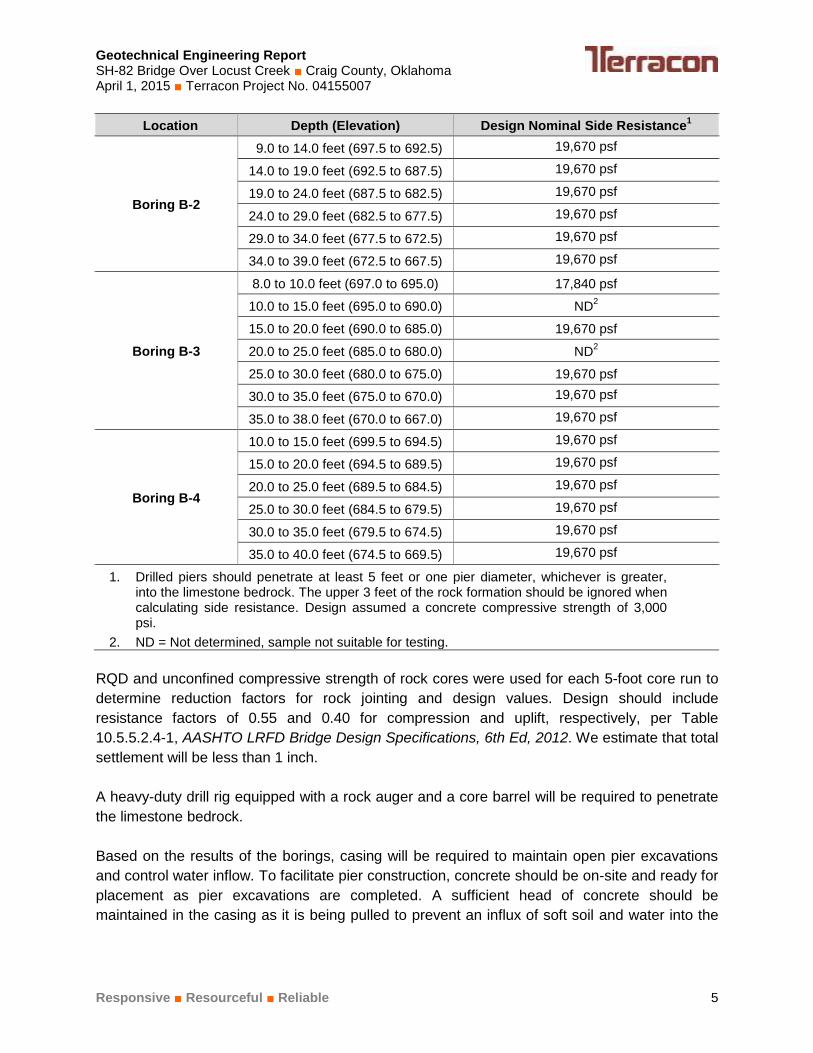
4.2 Drilled Piers
Straight shaft drilled piers bearing in the limestone bedrock can be used to support the interior
bents. We estimate drilled shafts properly socketed into the bedrock will not move downward
enough to fully develop end bearing resistance. Therefore, we recommend that drilled shafts be
designed using only side resistance. Drilled pier design recommendations are presented in the
following paragraphs.
Location Depth (Elevation) Design Nominal Side Resistance1
Boring B-1
10.0 to 15.0 feet (698.5 to 693.5) 19,670 psf
15.0 to 20.0 feet (693.5 to 688.5) 19,670 psf
20.0 to 25.0 feet (688.5 to 683.5) 19,670 psf
25.0 to 30.0 feet (683.5 to 678.5) 19,670 psf
30.0 to 35.0 feet (678.5 to 673.5) 19,670 psf
35.0 to 39.0 feet (673.5 to 669.5) 19,670 psf
Geotechnical Engineering Report SH-82 Bridge Over Locust Creek ■ Craig County, Oklahoma April 1, 2015 ■ Terracon Project No. 04155007
Responsive ■ Resourceful ■ Reliable 5
Location Depth (Elevation) Design Nominal Side Resistance1
Boring B-2
9.0 to 14.0 feet (697.5 to 692.5) 19,670 psf
14.0 to 19.0 feet (692.5 to 687.5) 19,670 psf
19.0 to 24.0 feet (687.5 to 682.5) 19,670 psf
24.0 to 29.0 feet (682.5 to 677.5) 19,670 psf
29.0 to 34.0 feet (677.5 to 672.5) 19,670 psf
34.0 to 39.0 feet (672.5 to 667.5) 19,670 psf
Boring B-3
8.0 to 10.0 feet (697.0 to 695.0) 17,840 psf
10.0 to 15.0 feet (695.0 to 690.0) ND2
15.0 to 20.0 feet (690.0 to 685.0) 19,670 psf
20.0 to 25.0 feet (685.0 to 680.0) ND2
25.0 to 30.0 feet (680.0 to 675.0) 19,670 psf
30.0 to 35.0 feet (675.0 to 670.0) 19,670 psf
35.0 to 38.0 feet (670.0 to 667.0) 19,670 psf
Boring B-4
10.0 to 15.0 feet (699.5 to 694.5) 19,670 psf
15.0 to 20.0 feet (694.5 to 689.5) 19,670 psf
20.0 to 25.0 feet (689.5 to 684.5) 19,670 psf
25.0 to 30.0 feet (684.5 to 679.5) 19,670 psf
30.0 to 35.0 feet (679.5 to 674.5) 19,670 psf
35.0 to 40.0 feet (674.5 to 669.5) 19,670 psf
1. Drilled piers should penetrate at least 5 feet or one pier diameter, whichever is greater, into the limestone bedrock. The upper 3 feet of the rock formation should be ignored when calculating side resistance. Design assumed a concrete compressive strength of 3,000 psi.
2. ND = Not determined, sample not suitable for testing.
RQD and unconfined compressive strength of rock cores were used for each 5-foot core run to
determine reduction factors for rock jointing and design values. Design should include
resistance factors of 0.55 and 0.40 for compression and uplift, respectively, per Table
10.5.5.2.4-1, AASHTO LRFD Bridge Design Specifications, 6th Ed, 2012. We estimate that total
settlement will be less than 1 inch.
A heavy-duty drill rig equipped with a rock auger and a core barrel will be required to penetrate
the limestone bedrock.
Based on the results of the borings, casing will be required to maintain open pier excavations
and control water inflow. To facilitate pier construction, concrete should be on-site and ready for
placement as pier excavations are completed. A sufficient head of concrete should be
maintained in the casing as it is being pulled to prevent an influx of soft soil and water into the

Geotechnical Engineering Report SH-82 Bridge Over Locust Creek ■ Craig County, Oklahoma April 1, 2015 ■ Terracon Project No. 04155007
Responsive ■ Resourceful ■ Reliable 6
excavations. Also, concrete having a slump of at least 5 inches should be used to prevent the
concrete from arching in the casing.
GENERAL COMMENTS 5.0
Terracon should be retained to review the final design plans and specifications so comments
can be made regarding interpretation and implementation of our geotechnical recommendations
in the design and specifications. Terracon also should be retained to provide observation and
testing services during grading, excavation, foundation construction and other earth-related
construction phases of the project.
The analysis and recommendations presented in this report are based upon the data obtained
from the borings performed at the indicated locations and from other information discussed in
this report. This report does not reflect variations that may occur between borings, across the
site, or due to the modifying effects of construction or weather. The nature and extent of such
variations may not become evident until during or after construction. If variations appear, we
should be immediately notified so that further evaluation and supplemental recommendations
can be provided.
The scope of services for this project does not include either specifically or by implication any
environmental or biological (e.g., mold, fungi, bacteria) assessment of the site or identification or
prevention of pollutants, hazardous materials or conditions. If the owner is concerned about the
potential for such contamination or pollution, other studies should be undertaken.
This report has been prepared for the exclusive use of our client for specific application to the
project discussed and has been prepared in accordance with generally accepted geotechnical
engineering practices. No warranties, either express or implied, are intended or made. Site
safety, excavation support, and dewatering requirements are the responsibility of others. In the
event that changes in the nature, design, or location of the project as outlined in this report are
planned, the conclusions and recommendations contained in this report shall not be considered
valid unless Terracon reviews the changes and either verifies or modifies the conclusions of this
report in writing.
APPENDIX A
FIELD EXPLORATION
Project Mngr:
Approved By:
Checked By:
Drawn By:
Project No.
Scale:
Date:
File No.Consulting Engineers and Scientists
EXHIBIT NO.
9522 EAST 47TH PLACE, UNIT D TULSA, OKLAHOMA 74145FAX. (918) 250-4570PH. (918) 250-0461
FAR
JM
FAR
MHH
04155007
SEE BAR SCALE
04155007
APRIL 2015
SITE LOCATION MAP
A-1GEOTECHNICAL EXPLORATION
SH-82 BRIDGE OVER LOCUST CREEKCRAIG COUNTY, OKLAHOMA
N© 2015 GOOGLE
APPROXIMATE SCALE IN FEET
3000 0 2000 30001000
APPROXIMATE SITE LOCATION

FAR JM FAR
MHH
0415
5007
SEE
BAR
SCAL
E
0415
5007
APRI
L 201
5
BORI
NG LO
CATI
ON P
LAN
A-2
GEOT
ECHN
ICAL
EXP
LORA
TION
SH-8
2 BRI
DGE
OVER
LOCU
ST C
REEK
CRAI
G CO
UNTY
, OKL
AHOM
A
BORI
NGST
ATIO
NOF
FSET
**EL
EV. (
FT)
B-1
346+
770'
708.5
B-2
347+
270'
706.5
B-3
348+
070'
705.0
B-4
348+
570'
709.5
** ST
ATIO
NS A
ND O
FFSE
TS B
ASED
ON
PROP
OSED
ROA
D CL
LEGE
NDBO
RING
LOCA
TION
DIAG
RAM
IS F
OR G
ENER
AL LO
CATI
ON O
NLY,
AN
D IS
NOT
INTE
NDED
FOR
CON
STRU
CTIO
N PU
RPOS
ES
N A
PPRO
XIMA
TE S
CALE
IN F
EET
400
2040
3010
© 2015 OKLAHOMA DEPT. OF TRANSPORTATION
B-1
B-2
B-3
B-4
Geotechnical Engineering Report SH-82 Bridge Over Locust Creek ■ Craig County, Oklahoma April 1, 2015 ■ Terracon Project No. 04155007
Responsive ■ Resourceful ■ Reliable Exhibit A-3
Field Exploration Description
The borings were performed at the approximate locations shown on the Boring Location Plan in
this Appendix. Terracon’s drill crew laid out the borings by measuring horizontal distances with a
tape. Surface elevations at the boring locations were obtained by the drill crew using a
surveyor's level and rod and were referenced to Benchmark 104 shown on the Plan and Profile
sheets provided by the Oklahoma Department of Transportation. An elevation of 716.67 feet
was used for the benchmark. The locations and elevations of the borings should be considered
accurate only to the degree implied by the means and methods used to define them.
The borings were advanced with an all-terrain rotary drill rig using wash boring techniques.
Representative samples were obtained by the split-barrel sampling procedure in which a
standard 2-inch, O.D. split-barrel sampling spoon is driven into the bottom of the boring with a
140-pound drive hammer falling 30 inches. The number of blows required to advance the
sampling spoon the last 12 inches, or less, of an 18-inch sampling interval or portion thereof, is
recorded as the standard penetration resistance value, N. The N value is used to estimate the
in-situ relative density of granular soils and, to a lesser degree of accuracy, the consistency of
cohesive soils and the hardness of weathered bedrock. The sampling depths, penetration
distances, and N values are reported on the boring logs. The samples were tagged for
identification, sealed to reduce moisture loss and returned to the laboratory for further
examination, testing and classification.
An automatic drive hammer was used to advance the split-barrel. A greater efficiency is
achieved with the automatic drive hammer compared to the conventional safety drive hammer
operated with a cathead and rope.
Core samples of bedrock materials were obtained using an NX-size diamond-bit core barrel.
The percentages of rock core recovered (%REC) and Rock Quality Designation (RQD) per
length of core run are shown on the boring logs. The RQD is an index obtained by summing the
lengths of rock core pieces that are 4 inches in length or longer divided by the total length of
core run. The percent recovery and RQD values are shown on the boring logs in Appendix A.
The drilling operation was supervised by a field engineer, who prepared field logs. The boring
logs include visual classifications of the materials encountered during drilling and the engineer’s
interpretation of subsurface conditions between samples. Based on the material’s texture, the
soil samples were described according to the attached General Notes and classified in
accordance with the Unified Soil Classification System. A brief description of the Unified System
is included in Appendix C. Rock descriptions are in general accordance with the General Notes
for Sedimentary Rock. Core samples and petrographic analysis may reveal other rock types.
As required by the Oklahoma Water Resources Board, any borings deeper than 20 feet, or
borings which encounter groundwater or contaminated materials must be grouted or plugged in
accordance with Oklahoma State statutes. One boring log must also be submitted to the
Geotechnical Engineering Report SH-82 Bridge Over Locust Creek ■ Craig County, Oklahoma April 1, 2015 ■ Terracon Project No. 04155007
Responsive ■ Resourceful ■ Reliable Exhibit A-3
Oklahoma Water Resources Board for each 10 acres of project site area. Terracon backfilled
the borings to comply with the Oklahoma Water Resources Board requirements.
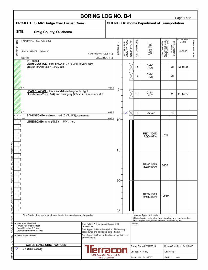
5.0
9.0
10.0
3" TopsoilLEAN CLAY (CL), dark brown (10 YR, 3/3) to very darkgrayish-brown (2.5 Y, 3/2), stiff
LEAN CLAY (CL), trace sandstone fragments, lightolive-brown (2.5 Y, 5/4) and dark gray (2.5 Y, 4/1), medium stiff
SANDSTONE+, yellowish red (5 YR, 5/8), cemented
LIMESTONE+, gray (GLEY 1, 5/N), hard
3-4-5N=9
2-4-4N=8
2-3-4N=7
3-50/4"
REC=100%RQD=97%
REC=100%RQD=100%
REC=100%RQD=100%
9750
8460
10560
21
21
23
19
42-16-26
41-14-27
703.5
699.5
698.5
18
18
18
10
Hammer Type: Automatic+Classification estimated from disturbed and core samples.Petrographic analysis may reveal other rock types.
Stratification lines are approximate. In-situ, the transition may be gradual.
LOCATION
DEPTH
GR
AP
HIC
LO
G
Station: 346+77 Offset: 0'
See Exhibit A-2
TH
IS B
OR
ING
LO
G IS
NO
T V
ALI
D IF
SE
PA
RA
TE
D F
RO
M O
RIG
INA
L R
EP
OR
T.
G
EO
SM
AR
T L
OG
-NO
WE
LL 0
415
500
7.G
PJ
Craig County, OklahomaSITE:
Page 1 of 2
Advancement Method:Power Auger to 9.3 feetRock Bit below 9.3 feetDiamond Bit below 10 feet
Abandonment Method:
9522 East 47th Place, Unit DTulsa, Oklahoma
Notes:
Project No.: 04155007
Drill Rig: ATV 840
Boring Started: 3/12/2015
BORING LOG NO. B-1Oklahoma Department of TransportationCLIENT:
Driller: TS
Boring Completed: 3/12/2015
Exhibit: A-4
See Exhibit A-3 for description of fieldprocedures.See Appendix B for description of laboratoryprocedures and additional data (if any).
See Appendix C for explanation of symbols andabbreviations.
PROJECT: SH-82 Bridge Over Locust Creek
FIE
LD T
ES
TR
ES
ULT
S
UN
CO
NF
INE
DC
OM
PR
ES
SIV
ES
TR
EN
GT
H (
psi)
PE
RC
EN
T F
INE
S
WA
TE
RC
ON
TE
NT
(%
)
ATTERBERGLIMITS
LL-PL-PISurface Elev.: 708.5 (Ft.)
ELEVATION (Ft.)
SA
MP
LE T
YP
E
WA
TE
R L
EV
EL
OB
SE
RV
AT
ION
S
DE
PT
H (
Ft.)
5
10
15
20
25
RE
CO
VE
RY
(In
.)
WATER LEVEL OBSERVATIONS
9 ft While Drilling
39.0
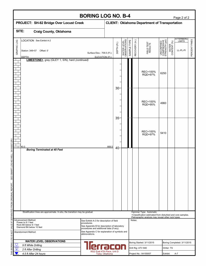
LIMESTONE+, gray (GLEY 1, 5/N), hard (continued)
Boring Terminated at 39 Feet
REC=100%RQD=90%
REC=100%RQD=100%
REC = 75%RQD = 75%
7030
13400
11600
669.5
Hammer Type: Automatic+Classification estimated from disturbed and core samples.Petrographic analysis may reveal other rock types.
Stratification lines are approximate. In-situ, the transition may be gradual.
LOCATION
DEPTH
GR
AP
HIC
LO
G
Station: 346+77 Offset: 0'
See Exhibit A-2
TH
IS B
OR
ING
LO
G IS
NO
T V
ALI
D IF
SE
PA
RA
TE
D F
RO
M O
RIG
INA
L R
EP
OR
T.
G
EO
SM
AR
T L
OG
-NO
WE
LL 0
415
500
7.G
PJ
Craig County, OklahomaSITE:
Page 2 of 2
Advancement Method:Power Auger to 9.3 feetRock Bit below 9.3 feetDiamond Bit below 10 feet
Abandonment Method:
9522 East 47th Place, Unit DTulsa, Oklahoma
Notes:
Project No.: 04155007
Drill Rig: ATV 840
Boring Started: 3/12/2015
BORING LOG NO. B-1Oklahoma Department of TransportationCLIENT:
Driller: TS
Boring Completed: 3/12/2015
Exhibit: A-4
See Exhibit A-3 for description of fieldprocedures.See Appendix B for description of laboratoryprocedures and additional data (if any).
See Appendix C for explanation of symbols andabbreviations.
PROJECT: SH-82 Bridge Over Locust Creek
FIE
LD T
ES
TR
ES
ULT
S
UN
CO
NF
INE
DC
OM
PR
ES
SIV
ES
TR
EN
GT
H (
psi)
PE
RC
EN
T F
INE
S
WA
TE
RC
ON
TE
NT
(%
)
ATTERBERGLIMITS
LL-PL-PISurface Elev.: 708.5 (Ft.)
ELEVATION (Ft.)
SA
MP
LE T
YP
E
WA
TE
R L
EV
EL
OB
SE
RV
AT
ION
S
DE
PT
H (
Ft.)
30
35
RE
CO
VE
RY
(In
.)
WATER LEVEL OBSERVATIONS
9 ft While Drilling
2.0
8.59.0
3" TopsoilFAT CLAY (CH), with sand, dark brown (10 YR, 3/3), mediumstiff
LEAN CLAY/FAT CLAY (CL-CH), trace sandstone fragments,light olive-brown (2.5 Y, 5/4) to very dark grayish-brown (2.5 Y,3/2), medium stiff to stiff
SANDSTONE+, yellowish red (5 YR, 5/8), poorly cemented tocementedLIMESTONE+, gray (GLEY 1, 5/N), hard
1-2-2N=4
1-4-4N=8
2-3-4N=7
50/6"
REC=100%RQD=97%
REC=100%RQD=97%
REC=100%RQD=95%
11200
8380
27900
21
23
25
21
47-20-27
704.5
698697.5
18
18
18
6
Hammer Type: Automatic+Classification estimated from disturbed and core samples.Petrographic analysis may reveal other rock types.
Stratification lines are approximate. In-situ, the transition may be gradual.
LOCATION
DEPTH
GR
AP
HIC
LO
G
Station: 347+27 Offset: 0'
See Exhibit A-2
TH
IS B
OR
ING
LO
G IS
NO
T V
ALI
D IF
SE
PA
RA
TE
D F
RO
M O
RIG
INA
L R
EP
OR
T.
G
EO
SM
AR
T L
OG
-NO
WE
LL 0
415
500
7.G
PJ
Craig County, OklahomaSITE:
Page 1 of 2
Advancement Method:Power Auger to 9 feetDiamond Bit below 9 feet
Abandonment Method:
9522 East 47th Place, Unit DTulsa, Oklahoma
Notes:
Project No.: 04155007
Drill Rig: ATV 840
Boring Started: 3/11/2015
BORING LOG NO. B-2Oklahoma Department of TransportationCLIENT:
Driller: TS
Boring Completed: 3/11/2015
Exhibit: A-5
See Exhibit A-3 for description of fieldprocedures.See Appendix B for description of laboratoryprocedures and additional data (if any).
See Appendix C for explanation of symbols andabbreviations.
PROJECT: SH-82 Bridge Over Locust Creek
FIE
LD T
ES
TR
ES
ULT
S
UN
CO
NF
INE
DC
OM
PR
ES
SIV
ES
TR
EN
GT
H (
psi)
PE
RC
EN
T F
INE
S
WA
TE
RC
ON
TE
NT
(%
)
ATTERBERGLIMITS
LL-PL-PISurface Elev.: 706.5 (Ft.)
ELEVATION (Ft.)
SA
MP
LE T
YP
E
WA
TE
R L
EV
EL
OB
SE
RV
AT
ION
S
DE
PT
H (
Ft.)
5
10
15
20
25
RE
CO
VE
RY
(In
.)
WATER LEVEL OBSERVATIONS
1 ft After Drilling
8.5 ft While Drilling
39.0
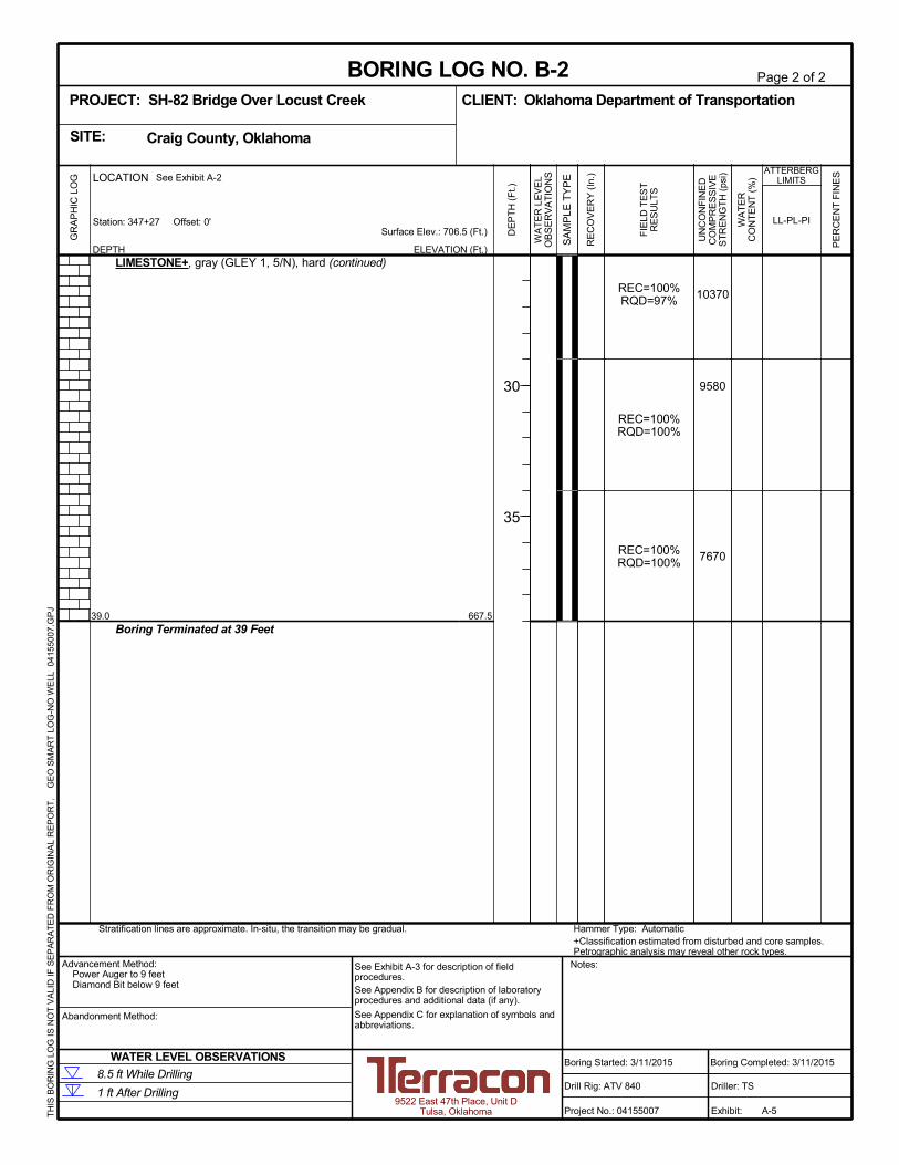
LIMESTONE+, gray (GLEY 1, 5/N), hard (continued)
Boring Terminated at 39 Feet
REC=100%RQD=97%
REC=100%RQD=100%
REC=100%RQD=100%
10370
9580
7670
667.5
Hammer Type: Automatic+Classification estimated from disturbed and core samples.Petrographic analysis may reveal other rock types.
Stratification lines are approximate. In-situ, the transition may be gradual.
LOCATION
DEPTH
GR
AP
HIC
LO
G
Station: 347+27 Offset: 0'
See Exhibit A-2
TH
IS B
OR
ING
LO
G IS
NO
T V
ALI
D IF
SE
PA
RA
TE
D F
RO
M O
RIG
INA
L R
EP
OR
T.
G
EO
SM
AR
T L
OG
-NO
WE
LL 0
415
500
7.G
PJ
Craig County, OklahomaSITE:
Page 2 of 2
Advancement Method:Power Auger to 9 feetDiamond Bit below 9 feet
Abandonment Method:
9522 East 47th Place, Unit DTulsa, Oklahoma
Notes:
Project No.: 04155007
Drill Rig: ATV 840
Boring Started: 3/11/2015
BORING LOG NO. B-2Oklahoma Department of TransportationCLIENT:
Driller: TS
Boring Completed: 3/11/2015
Exhibit: A-5
See Exhibit A-3 for description of fieldprocedures.See Appendix B for description of laboratoryprocedures and additional data (if any).
See Appendix C for explanation of symbols andabbreviations.
PROJECT: SH-82 Bridge Over Locust Creek
FIE
LD T
ES
TR
ES
ULT
S
UN
CO
NF
INE
DC
OM
PR
ES
SIV
ES
TR
EN
GT
H (
psi)
PE
RC
EN
T F
INE
S
WA
TE
RC
ON
TE
NT
(%
)
ATTERBERGLIMITS
LL-PL-PISurface Elev.: 706.5 (Ft.)
ELEVATION (Ft.)
SA
MP
LE T
YP
E
WA
TE
R L
EV
EL
OB
SE
RV
AT
ION
S
DE
PT
H (
Ft.)
30
35
RE
CO
VE
RY
(In
.)
WATER LEVEL OBSERVATIONS
1 ft After Drilling
8.5 ft While Drilling
2.0
6.0
8.0
3" TopsoilLEAN CLAY/FAT CLAY (CL-CH), dark brown (10 YR, 3/3),medium stiff
LEAN CLAY (CL), dark olive-brown (2.5 Y, 3/3), soft
-with sand at about 5 feet
SANDSTONE+, with limestone seams, gray (GLEY 1, 5/N),poorly cemented to well cemented
-auger refusal at 8 feetLIMESTONE+, gray (GLEY 1, 5/N), hard
18-2-4N=6
0-2-2N=4
2-3-50/5"
REC=75%RQD=25%
REC=100%RQD=92%
REC=100%RQD=90%
REC=100%RQD=97%
10640
11630
35
23
14
36-14-22
703
699
697
1
18
17
Hammer Type: Automatic+Classification estimated from disturbed and core samples.Petrographic analysis may reveal other rock types.
Stratification lines are approximate. In-situ, the transition may be gradual.
LOCATION
DEPTH
GR
AP
HIC
LO
G
Station: 348+07 Offset: 0'
See Exhibit A-2
TH
IS B
OR
ING
LO
G IS
NO
T V
ALI
D IF
SE
PA
RA
TE
D F
RO
M O
RIG
INA
L R
EP
OR
T.
G
EO
SM
AR
T L
OG
-NO
WE
LL 0
415
500
7.G
PJ
Craig County, OklahomaSITE:
Page 1 of 2
Advancement Method:Power Auger to 8 feetDiamond Bit below 8 feet
Abandonment Method:
9522 East 47th Place, Unit DTulsa, Oklahoma
Notes:
Project No.: 04155007
Drill Rig: ATV 840
Boring Started: 3/10/2015
BORING LOG NO. B-3Oklahoma Department of TransportationCLIENT:
Driller: TS
Boring Completed: 3/10/2015
Exhibit: A-6
See Exhibit A-3 for description of fieldprocedures.See Appendix B for description of laboratoryprocedures and additional data (if any).
See Appendix C for explanation of symbols andabbreviations.
PROJECT: SH-82 Bridge Over Locust Creek
FIE
LD T
ES
TR
ES
ULT
S
UN
CO
NF
INE
DC
OM
PR
ES
SIV
ES
TR
EN
GT
H (
psi)
PE
RC
EN
T F
INE
S
WA
TE
RC
ON
TE
NT
(%
)
ATTERBERGLIMITS
LL-PL-PISurface Elev.: 705 (Ft.)
ELEVATION (Ft.)
SA
MP
LE T
YP
E
WA
TE
R L
EV
EL
OB
SE
RV
AT
ION
S
DE
PT
H (
Ft.)
5
10
15
20
25
RE
CO
VE
RY
(In
.)
WATER LEVEL OBSERVATIONS
2 ft After Drilling
1 ft After 24 hours
7 ft While Drilling

38.0
LIMESTONE+, gray (GLEY 1, 5/N), hard (continued)
Boring Terminated at 38 Feet
REC=100%RQD=97%
REC=100%RQD=97%
REC=100%RQD=100%
8120
7530
8760
667
Hammer Type: Automatic+Classification estimated from disturbed and core samples.Petrographic analysis may reveal other rock types.
Stratification lines are approximate. In-situ, the transition may be gradual.
LOCATION
DEPTH
GR
AP
HIC
LO
G
Station: 348+07 Offset: 0'
See Exhibit A-2
TH
IS B
OR
ING
LO
G IS
NO
T V
ALI
D IF
SE
PA
RA
TE
D F
RO
M O
RIG
INA
L R
EP
OR
T.
G
EO
SM
AR
T L
OG
-NO
WE
LL 0
415
500
7.G
PJ
Craig County, OklahomaSITE:
Page 2 of 2
Advancement Method:Power Auger to 8 feetDiamond Bit below 8 feet
Abandonment Method:
9522 East 47th Place, Unit DTulsa, Oklahoma
Notes:
Project No.: 04155007
Drill Rig: ATV 840
Boring Started: 3/10/2015
BORING LOG NO. B-3Oklahoma Department of TransportationCLIENT:
Driller: TS
Boring Completed: 3/10/2015
Exhibit: A-6
See Exhibit A-3 for description of fieldprocedures.See Appendix B for description of laboratoryprocedures and additional data (if any).
See Appendix C for explanation of symbols andabbreviations.
PROJECT: SH-82 Bridge Over Locust Creek
FIE
LD T
ES
TR
ES
ULT
S
UN
CO
NF
INE
DC
OM
PR
ES
SIV
ES
TR
EN
GT
H (
psi)
PE
RC
EN
T F
INE
S
WA
TE
RC
ON
TE
NT
(%
)
ATTERBERGLIMITS
LL-PL-PISurface Elev.: 705 (Ft.)
ELEVATION (Ft.)
SA
MP
LE T
YP
E
WA
TE
R L
EV
EL
OB
SE
RV
AT
ION
S
DE
PT
H (
Ft.)
30
35
RE
CO
VE
RY
(In
.)
WATER LEVEL OBSERVATIONS
2 ft After Drilling
1 ft After 24 hours
7 ft While Drilling
2.0
5.0
9.5
3" TopsoilLEAN CLAY (CL), with sand, dark brown (10 YR, 3/3), mediumstiff
LEAN CLAY (CL), with sand, dark olive-brown (2.5 Y, 3/3),medium stiff
SANDY LEAN CLAY (CL), dark olive-brown (2.5 Y, 3/3),medium stiff
LIMESTONE+, gray (GLEY 1, 5/N), hard
1-3-3N=6
2-3-4N=7
2-3-3N=6
3-10-50/1"
REC=90%RQD=80%
REC=100%RQD=95%
REC=100%RQD=97%
8860
11620
7130
26
24
21
22
43-22-21
29-15-14
707.5
704.5
700
18
18
18
13
Hammer Type: Automatic+Classification estimated from disturbed and core samples.Petrographic analysis may reveal other rock types.
Stratification lines are approximate. In-situ, the transition may be gradual.
LOCATION
DEPTH
GR
AP
HIC
LO
G
Station: 348+57 Offset: 0'
See Exhibit A-2
TH
IS B
OR
ING
LO
G IS
NO
T V
ALI
D IF
SE
PA
RA
TE
D F
RO
M O
RIG
INA
L R
EP
OR
T.
G
EO
SM
AR
T L
OG
-NO
WE
LL 0
415
500
7.G
PJ
Craig County, OklahomaSITE:
Page 1 of 2
Advancement Method:Power to 9.1 feetRock Bit below 9.1 feetDiamond Bit below 10 feet
Abandonment Method:
9522 East 47th Place, Unit DTulsa, Oklahoma
Notes:
Project No.: 04155007
Drill Rig: ATV 840
Boring Started: 3/11/2015
BORING LOG NO. B-4Oklahoma Department of TransportationCLIENT:
Driller: TS
Boring Completed: 3/11/2015
Exhibit: A-7
See Exhibit A-3 for description of fieldprocedures.See Appendix B for description of laboratoryprocedures and additional data (if any).
See Appendix C for explanation of symbols andabbreviations.
PROJECT: SH-82 Bridge Over Locust Creek
FIE
LD T
ES
TR
ES
ULT
S
UN
CO
NF
INE
DC
OM
PR
ES
SIV
ES
TR
EN
GT
H (
psi)
PE
RC
EN
T F
INE
S
WA
TE
RC
ON
TE
NT
(%
)
ATTERBERGLIMITS
LL-PL-PISurface Elev.: 709.5 (Ft.)
ELEVATION (Ft.)
SA
MP
LE T
YP
E
WA
TE
R L
EV
EL
OB
SE
RV
AT
ION
S
DE
PT
H (
Ft.)
5
10
15
20
25
RE
CO
VE
RY
(In
.)
WATER LEVEL OBSERVATIONS
2 ft After Drilling
4.5 ft After 24 hours
9 ft While Drilling
40.0
LIMESTONE+, gray (GLEY 1, 5/N), hard (continued)
Boring Terminated at 40 Feet
REC=100%RQD=97%
REC=100%RQD=95%
REC=100%RQD=97%
6250
4960
5410
669.5
Hammer Type: Automatic+Classification estimated from disturbed and core samples.Petrographic analysis may reveal other rock types.
Stratification lines are approximate. In-situ, the transition may be gradual.
LOCATION
DEPTH
GR
AP
HIC
LO
G
Station: 348+57 Offset: 0'
See Exhibit A-2
TH
IS B
OR
ING
LO
G IS
NO
T V
ALI
D IF
SE
PA
RA
TE
D F
RO
M O
RIG
INA
L R
EP
OR
T.
G
EO
SM
AR
T L
OG
-NO
WE
LL 0
415
500
7.G
PJ
Craig County, OklahomaSITE:
Page 2 of 2
Advancement Method:Power to 9.1 feetRock Bit below 9.1 feetDiamond Bit below 10 feet
Abandonment Method:
9522 East 47th Place, Unit DTulsa, Oklahoma
Notes:
Project No.: 04155007
Drill Rig: ATV 840
Boring Started: 3/11/2015
BORING LOG NO. B-4Oklahoma Department of TransportationCLIENT:
Driller: TS
Boring Completed: 3/11/2015
Exhibit: A-7
See Exhibit A-3 for description of fieldprocedures.See Appendix B for description of laboratoryprocedures and additional data (if any).
See Appendix C for explanation of symbols andabbreviations.
PROJECT: SH-82 Bridge Over Locust Creek
FIE
LD T
ES
TR
ES
ULT
S
UN
CO
NF
INE
DC
OM
PR
ES
SIV
ES
TR
EN
GT
H (
psi)
PE
RC
EN
T F
INE
S
WA
TE
RC
ON
TE
NT
(%
)
ATTERBERGLIMITS
LL-PL-PISurface Elev.: 709.5 (Ft.)
ELEVATION (Ft.)
SA
MP
LE T
YP
E
WA
TE
R L
EV
EL
OB
SE
RV
AT
ION
S
DE
PT
H (
Ft.)
30
35
40
RE
CO
VE
RY
(In
.)
WATER LEVEL OBSERVATIONS
2 ft After Drilling
4.5 ft After 24 hours
9 ft While Drilling
Consulting Engineers and Scientists
9522 EAST 47TH PLACE, UNIT D TULSA, OKLAHOMA 74145FAX. (918) 250-4570PH. (918) 250-0461
~ "! ~ c;:
Ii! "-... u ~ "' "' la "' "' ~ :ii "' ~ 0
"' g
~ ;:;: 0
"' "-
b Q
"" 0
~
~ ~ !2 ... 0
"' ~ 8 i ~ ... "' ~ 0 ::I ;!
b :z !!!
§
"' :z iiii 0
"' ]Z_ !!! j!:
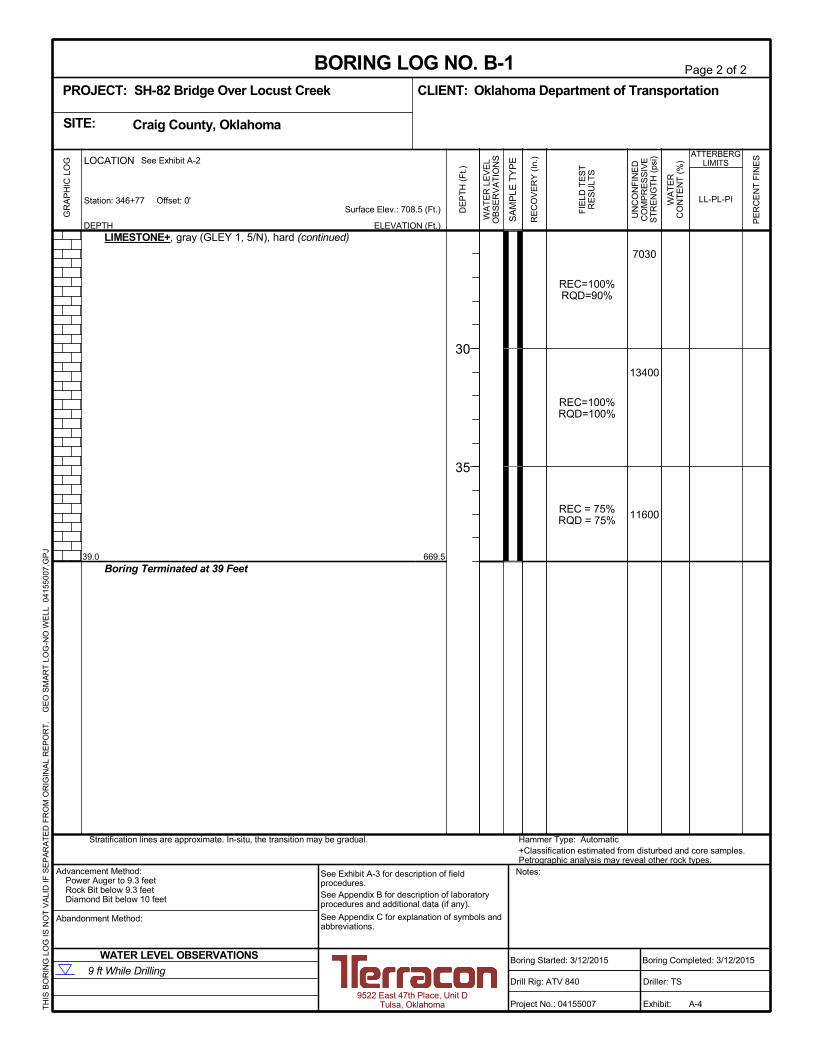
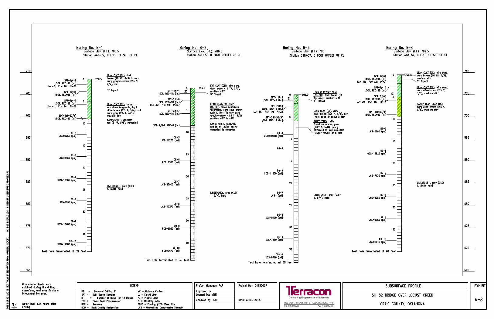
Boring No. B-1 Surface Elev. (rt.): 708.5 Station 346+ 77, 0 FOOT OFFSET OF CL
SPT-1;N=9 0 ;SOIL REC=l8 (In.) __
LL= 42; PL= 16; Pl=26
SPT-2;N=8 r;SOIL REC=18 (In.)
SPT-3;N=7 5 ;SOIL REC=18 (In.) __
LL= 41; PL= 14; Pl=27
SPT-4;N=50/ 4" ;SOIL REC=10 (In.)--¥- .
10
DB-5 UCS=9750 (psi)--
15
DB-6 UCS=8460 (psi)--
DB-7 UCS=10560 {psi)
DB-8 UCS=7030 (pst)
20
25
30
DB-9 UCS=13400 (psi)--
35
DB-10 UCS=l 1600 (psi)--
Test hole terminated at 39 feet
708.5 LEAN CLAY {CL), daric brown (10 YR, 3/3) to very dark grayish-brown (2.5 Y, 3/2), stiff
3" Topsoil
LEAN CLAY {CL), trace sandstone fragmenls, llQ.hl olive-brown (2.5 Y, 5/ 4 J and dark gray (2.5 Y, 4/1 ), medium stiff SANDSTONE+, ~llowtsh red {5 YR, 5/8), cemented
LIMESTONE+, gray {GLEY 1, 5/N), hard
Boring No. B-2 Surface Elev. (rt.): 706.5 Station 346+77, 0 FOOT OFFSET OF CL
0 SPT-1;N=4 JZ.
;SOIL REC=18 (In.)----
SPT-2;N=8 ;SOIL REC=18 (ln.)r
LL= 47; PL= 20; Pl=27
SPT-3;N=7 5 ;SOIL REC=18 (In.)--
SPT-4;SOIL REC=6 (In.) __ .
10
DB-5 UCS=11200 (psi)--
DB-6 UCS=8380 (psi)
15
20
DB-7 UCS=27900 (psi)--
25
DB-8 UCS=10370 (psi)--
DB-9 UCS=9580 (psi)
DB-10 UCS=7670 (psi)
30
35
Test hole terminated at 39 feet
706.5 FAT CLAY CH , wHh sand, daric brown 10 YR, 3/3), m1dium stiff 3" Topsoll
y CL-CH , trace sandstone
fragments, light olive-brown (2.5 Y, 5/4) lo very dark grayish-brown {2.5 Y, 3/2), medium stiff to sHff
SANDSTONE+, )'ellowlsh red {5 YR, 5/8), poorly cemented lo cemenled
LIMESTONE+, gray (GLEY 1, 5/N), hard
Borin~ No. B-3 u rface Elev. (rt.): 705
Station 348+07, 0 FOOT OFFSET OF CL
0 SPT-1;N=6 JZ.
;SOIL REC=1 (In.)----
SPT-2;N=4 ;SOIL REC=18 (ln.)r
LL= 36; PL= 14; Pl=22
SPT-3;N=50/5" 5 ;SOIL REC=17 {In.)--.
DB-4 UCS=10640 (psl)--
10
DB-5
DB-6 UCS= 11630 (psi)
15
20
25
DB-8 UCS=8120 (psi)--
DB-9 UCS=7530 (psi)
DB-10 UCS=8760 (psi)
30
35
Test hole terminated at 38 feet
705.0 LEAN CLAY/W CLAY .(Cl.::tlj), daric brown (10 YR, 3/3), medium stiff 3" TopllOll
LEAN CLAY (CIJ, dark olive-brown (2.5 Y, 3/3), soft -with sand at about 5 feel
SANDSTONE+, with limestone seams, gray (GLEY 1, 5/N), poorly cemenlad to wall cemented -auger refusal al 8 feel
LIMESTONE+, gray {GLEY 1, 5/N), hard
Groundwater levels were oblalnad during the drilling operations, and may fluctuate throughout the year.
LEGEND Project Manager: FAR Project No.: 04155007
llerracon Water level +24 houn after drilling
DB = Diamond Drilllng Bl! SPT = Split Spoon Sampler N Number of Blow1 for 12 Inches TCP = Texas Cone Penelromelar REC = Recovery RQD = Rock Quali Desi nation
MC = Moisture Content LL = Liquid Limit PL = Plasttc Limlt Pl = Plosttclly Index P200 = Passing #200 Steve Size UCS = Unconfined Com ressive Siren th
Approved or Lo ad b : MHH
Checked by: f AR Date: APRIL 2015
Boring No. B-4 Surface Elev. (rt.): 709.5 Station 348+57, 0 FOOT OFFSET OF CL
LEAN CLAY CL , wtth sand, SPT-l;N=6 0 """~-Aili.ii-- dar1c brown 10 YR, 3/3),
;SOIL REC=l8 (In.)__ medium stiff LL= 43; PL= 22; Pl=21 3• Topsoil
SPT-2;N=7 ~ LEAN CLAY (CL). wtth sand, ;SOIL REC=IB (lnY dar1c olive-brown (2.5 Y,
.¥ 3/3), medium still SPT-3;N=6 5
;SOIL REC=l8 {In.) __ LL= 29; PL= 15; Pl=l4
SPT-4;N=50/1" ;SOIL REC=l3 (ln.)--
DB-5 UCS=8860 {psi)
DB-6 UCS=11620 (psl)
10
15
20
DB-7 UCS=7130 (psi)--
DB-8 UCS=6250 (psi)--
DB-9 UCS=4960 {pst)
30
35
DB-10 UCS=5410 (psi)--
Test hole terminated at 40 feet
SANDY LEAN CLAY (CIJ, dar1c olive-brown (2.5 Y, 3/3), medium stllf
LIMESTONE+, gray (GLEY 1, 5/N), hard
SUBSURFACE PROFILE
SH-82 BRIDGE OVER LOCUST CREEK
CRAIG COUNTY, OKLAHO~A
EXHIBIT
A-8
APPENDIX B
SUPPORTING INFORMATION

Geotechnical Engineering Report SH-82 Bridge Over Locust Creek ■ Craig County, Oklahoma April 1, 2015 ■ Terracon Project No. 04155007
Responsive ■ Resourceful ■ Reliable Exhibit B-1
Laboratory Testing
Samples retrieved during the field exploration were taken to the laboratory for further
observation by the project geotechnical engineer and were classified in accordance with the
Unified Soil Classification System (USCS) described in Appendix C. After the testing was
completed, the field descriptions were confirmed or modified as necessary.
Selected soil and bedrock samples obtained from the site were tested for the following
engineering properties:
Water content
Atterberg limits
Unconfined compressive strength of rock cores
APPENDIX C
SUPPORTING DOCUMENTS

TraceWithModifier
Water Level Aftera Specified Period of Time
GRAIN SIZE TERMINOLOGYRELATIVE PROPORTIONS OF SAND AND GRAVEL
TraceWithModifier
Standard Penetration orN-Value
Blows/Ft.
Descriptive Term(Consistency)
Loose
Very Stiff
Exhibit C-1
Standard Penetration orN-Value
Blows/Ft.
Ring SamplerBlows/Ft.
Ring SamplerBlows/Ft.
Medium Dense
Dense
Very Dense
0 - 1 < 3
4 - 9 2 - 4 3 - 4
Medium-Stiff 5 - 9
30 - 50
WA
TE
R L
EV
EL
Auger
Shelby Tube
Ring Sampler
Grab Sample
8 - 15
Split Spoon
Macro Core
Rock Core
PLASTICITY DESCRIPTION
Term
< 1515 - 29> 30
Descriptive Term(s)of other constituents
Water InitiallyEncountered
Water Level After aSpecified Period of Time
Major Componentof Sample
Percent ofDry Weight
(More than 50% retained on No. 200 sieve.)Density determined by Standard Penetration Resistance
Includes gravels, sands and silts.
Hard
Very Loose 0 - 3 0 - 6 Very Soft
7 - 18 Soft
10 - 29 19 - 58
59 - 98 Stiff
less than 500
500 to 1,000
1,000 to 2,000
2,000 to 4,000
4,000 to 8,000> 99
LOCATION AND ELEVATION NOTES
SA
MP
LIN
G
FIE
LD
TE
ST
S
(HP)
(T)
(b/f)
(PID)
(OVA)
DESCRIPTION OF SYMBOLS AND ABBREVIATIONS
Descriptive Term(Density)
Non-plasticLowMediumHigh
BouldersCobblesGravelSandSilt or Clay
10 - 18
> 50 15 - 30 19 - 42
> 30 > 42
_
Hand Penetrometer
Torvane
Standard PenetrationTest (blows per foot)
Photo-Ionization Detector
Organic Vapor Analyzer
Water levels indicated on the soil boringlogs are the levels measured in theborehole at the times indicated.Groundwater level variations will occurover time. In low permeability soils,accurate determination of groundwaterlevels is not possible with short termwater level observations.
CONSISTENCY OF FINE-GRAINED SOILS
(50% or more passing the No. 200 sieve.)Consistency determined by laboratory shear strength testing, field
visual-manual procedures or standard penetration resistance
DESCRIPTIVE SOIL CLASSIFICATION
> 8,000
Unless otherwise noted, Latitude and Longitude are approximately determined using a hand-held GPS device. The accuracyof such devices is variable. Surface elevation data annotated with +/- indicates that no actual topographical survey wasconducted to confirm the surface elevation. Instead, the surface elevation was approximately determined from topographicmaps of the area.
Soil classification is based on the Unified Soil Classification System. Coarse Grained Soils have more than 50% of their dryweight retained on a #200 sieve; their principal descriptors are: boulders, cobbles, gravel or sand. Fine Grained Soils haveless than 50% of their dry weight retained on a #200 sieve; they are principally described as clays if they are plastic, andsilts if they are slightly plastic or non-plastic. Major constituents may be added as modifiers and minor constituents may beadded according to the relative proportions based on grain size. In addition to gradation, coarse-grained soils are definedon the basis of their in-place relative density and fine-grained soils on the basis of their consistency.
Plasticity Index
01 - 1011 - 30
> 30
RELATIVE PROPORTIONS OF FINES
Descriptive Term(s)of other constituents
Percent ofDry Weight
< 55 - 12> 12
No Recovery
RELATIVE DENSITY OF COARSE-GRAINED SOILS
Particle Size
Over 12 in. (300 mm)12 in. to 3 in. (300mm to 75mm)3 in. to #4 sieve (75mm to 4.75 mm)#4 to #200 sieve (4.75mm to 0.075mmPassing #200 sieve (0.075mm)
ST
RE
NG
TH
TE
RM
S Unconfined CompressiveStrength, Qu, psf
4 - 8
GENERAL NOTES
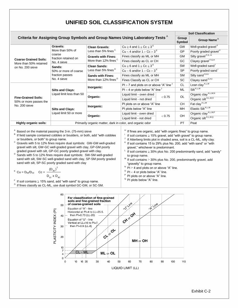
Exhibit C-2
UNIFIED SOIL CLASSIFICATION SYSTEM
Criteria for Assigning Group Symbols and Group Names Using Laboratory Tests A
Soil Classification
Group
Symbol Group Name
B
Coarse Grained Soils:
More than 50% retained
on No. 200 sieve
Gravels:
More than 50% of
coarse
fraction retained on
No. 4 sieve
Clean Gravels:
Less than 5% fines C
Cu 4 and 1 Cc 3 E
GW Well-graded gravel F
Cu 4 and/or 1 Cc 3 E
GP Poorly graded gravel F
Gravels with Fines:
More than 12% fines C
Fines classify as ML or MH GM Silty gravel F,G, H
Fines classify as CL or CH GC Clayey gravel F,G,H
Sands:
50% or more of coarse
fraction passes
No. 4 sieve
Clean Sands:
Less than 5% fines D
Cu 6 and 1 Cc 3 E
SW Well-graded sand I
Cu 6 and/or 1 Cc 3 E
SP Poorly graded sand I
Sands with Fines:
More than 12% fines D
Fines classify as ML or MH SM Silty sand G,H,I
Fines Classify as CL or CH SC Clayey sand G,H,I
Fine-Grained Soils:
50% or more passes the
No. 200 sieve
Silts and Clays:
Liquid limit less than 50
Inorganic: PI 7 and plots on or above “A” line
J CL Lean clay
K,L,M
PI 4 or plots below “A” line J ML Silt
K,L,M
Organic: Liquid limit - oven dried
0.75 OL Organic clay
K,L,M,N
Liquid limit - not dried Organic silt K,L,M,O
Silts and Clays:
Liquid limit 50 or more
Inorganic: PI plots on or above “A” line CH Fat clay
K,L,M
PI plots below “A” line MH Elastic Silt K,L,M
Organic: Liquid limit - oven dried
0.75 OH Organic clay
K,L,M,P
Liquid limit - not dried Organic silt K,L,M,Q
Highly organic soils: Primarily organic matter, dark in color, and organic odor PT Peat
A Based on the material passing the 3-in. (75-mm) sieve
B If field sample contained cobbles or boulders, or both, add “with cobbles
or boulders, or both” to group name. C
Gravels with 5 to 12% fines require dual symbols: GW-GM well-graded
gravel with silt, GW-GC well-graded gravel with clay, GP-GM poorly
graded gravel with silt, GP-GC poorly graded gravel with clay. D
Sands with 5 to 12% fines require dual symbols: SW-SM well-graded
sand with silt, SW-SC well-graded sand with clay, SP-SM poorly graded
sand with silt, SP-SC poorly graded sand with clay
E Cu = D60/D10 Cc =
6010
2
30
DxD
)(D
F If soil contains 15% sand, add “with sand” to group name.
G If fines classify as CL-ML, use dual symbol GC-GM, or SC-SM.
H If fines are organic, add “with organic fines” to group name.
I If soil contains 15% gravel, add “with gravel” to group name.
J If Atterberg limits plot in shaded area, soil is a CL-ML, silty clay.
K If soil contains 15 to 29% plus No. 200, add “with sand” or “with
gravel,” whichever is predominant. L
If soil contains 30% plus No. 200 predominantly sand, add “sandy”
to group name. M
If soil contains 30% plus No. 200, predominantly gravel, add
“gravelly” to group name. N
PI 4 and plots on or above “A” line. O
PI 4 or plots below “A” line. P
PI plots on or above “A” line. Q
PI plots below “A” line.

GENERAL NOTES Sedimentary Rock Classification
DESCRIPTIVE ROCK CLASSIFICATION:
LIMESTONE
DOLOMITE
CHERT
SHALE
SANDSTONE
CONGLOMERATE
Sedimentary rocks are composed of cemented clay, silt and sand sized particles. The most common minerals are clay, quartz and calcite. Rock composed primarily of calcite is called limestone; rock of sand size grains is called sandstone, and rock of clay and silt size grains is called mudstone or claystone, siltstone, or shale. Modifiers such as shaly, sandy, dolomitic, calcareous, carbonaceous, etc. are used to describe various constituents. Examples: sandy shale; calcareous sandstone.
Light to dark colored, crystalline to fine-grained texture, composed of CaCo,, reacts readily with HCI.
Light to dark colored, crystalline to fine-grained texture, composed of CaMg(C03)>, harder than limestone, reacts with HCI when powdered.
Light to dark colored, very fine-grained texture, composed of micro-crystalline quartz (Si02), brittle, breaks into angular fragments, will scratch glass.
Very fine-grained texture, composed of consolidated silt or clay, bedded in thin layers. The unlaminated equivalent is frequently referred to as siltstone, claystone or mudstone.
Usually light colored, coarse to fine texture, composed of cemented sand size grains of quartz, feldspar, etc. Cement usually is silica but may be such minerals as calcite, iron-oxide, or some other carbonate.
Rounded rock fragments of variable mineralogy varying in size from near sand to boulder size but usually pebble to cobble size (V2 inch to 6 inches). Cemented together with various cementing agents. Breccia is similar but composed of angular, fractured rock particles cemented together.
PHYSICAL PROPERTIES:
DEGREE OF WEATHERING
Slight
Moderate
High
Slight decomposition of parent material on joints. May be color change.
Some decomposition and color change throughout.
Rock highly decomposed, may be extremely broken.
HARDNESS AND DEGREE OF CEMENTATION
Limestone and Dolomite:
Hard Difficult to scratch with knife.
Moderately Hard
Soft
Can be scratched easily with knife, cannot be scratched with fingernail.
Can be scratched with fingernail.
Shale, Siltstone and Claystone
Hard
Moderately Hard
Soft
Can be scratched easily with knife, cannot be scratched with fingernail.
Can be scratched with fingernail.
Can be easily dented but not molded with fingers.
Sandstone and Conglomerate
Well Capable of scratching a knife blade. Cemented
Cemented
Poorly Cemented
Can be scratched with knife.
Can be broken apart easily with fingers.
BEDDING AND JOINT CHARACTERISTICS
Bed Thickness Very Thick
Thick Medium
Thin Very Thin Laminated
Joint Spacing Very Wide
Wide Moderately Close
Close Very Close
Dimensions >10'
3' - 10' 1' - 3' 2" - 1'
.4" - 2"
.1" - .4"
Bedding Plane A plane dividing sedimentary rocks of the same or different lithology.
Joint
Seam
Fracture in rock, generally more or less vertical or transverse to bedding, along which no appreciable movement has occurred.
Generally applies to bedding plane with an unspecified degree of weathering.
SOLUTION AND VOID CONDITIONS
Solid
Vuggy (Pitted)
Porous
Cavernous
Contains no voids.
Rock having small solution pits or cavities up to V2 inch diameter, frequently with a mineral lining.
Containing numerous voids, pores, or other openings, which may or may not interconnect.
Containing cavities or caverns, sometimes quite large.
__________ llerracon_ Form 110-6·85