geotechnical exploration report crosswinds church, lanvale...
TRANSCRIPT

Geotechnical Exploration Report
Crosswinds Church, Lanvale Road
Leland, North Carolina
S&ME Project No. 1306-15-047
Prepared for:
Crosswinds Church
485 Olde Waterford Way, Suite 101
Leland, NC 28451
Prepared by:
S&ME, Inc.
3006 Hall Waters Dr, Ste 100
Wilmington, NC 28405
January 27, 2016Reviewed For Code Compliance

Reviewed For Code Compliance
Reviewed For Code Compliance

Geotechnical Exploration Report
Crosswinds Church, Lanvale Road
Leland, North Carolina
S&ME Project No. 1306-15-047
January 27, 2016 ii
Table of Contents
1.0 Project Information ............................................................................................... 1
1.1 Information Sources .........................................................................................................1
1.2 Site Description.................................................................................................................1
1.3 Project Description ...........................................................................................................1
1.4 Assumptions......................................................................................................................1
2.0 Field Exploration Program................................................................................... 2
2.1 Cone Penetrometer Test Soundings...............................................................................2
2.2 Hand Auger Borings ........................................................................................................2
3.0 Subsurface Conditions ......................................................................................... 3
3.1 Physiography and Area Geology ...................................................................................3
3.2 Soil Survey.........................................................................................................................3
3.3 Soundings and Borings....................................................................................................4
3.3.1 Surface Materials ................................................................................................................4
3.3.2 Very Loose to Medium Dense Sand ....................................................................................4
3.3.3 Soft Clay ..............................................................................................................................4
3.3.4 Medium Dense to Dense Sand ............................................................................................4
3.3.5 Groundwater .......................................................................................................................5
4.0 Conclusions and Recommendations ................................................................. 5
4.1 Management of Shallow Groundwater .........................................................................5
4.2 Site Preparation.................................................................................................................5
4.3 Excavation Considerations..............................................................................................6
4.3.1 Temporary Sloping and/or Shoring.....................................................................................6
4.3.2 Construction Dewatering....................................................................................................7
4.4 Structural Fill and Backfill...............................................................................................7
4.4.1 Placement and Compaction .................................................................................................7
4.4.2 Use of On-Site Soil ..............................................................................................................8
4.5 Seismic Design ..................................................................................................................9
4.5.1 General ................................................................................................................................9
4.5.2 Seismic Site Class................................................................................................................9
Reviewed For Code Compliance

Geotechnical Exploration Report
Crosswinds Church, Lanvale Road
Leland, North Carolina
S&ME Project No. 1306-15-047
January 27, 2016 iii
4.5.3 Ground Motion Parameters ................................................................................................9
4.5.4 Liquefaction Evaluation ......................................................................................................9
4.6 Foundations.....................................................................................................................10
4.7 Ground Floor Slabs.........................................................................................................11
5.0 Limitations of Geotechnical Report................................................................. 11
List of FiguresFigure 3-1 - Physiography..........................................................................................................................3
List of TablesTable 3-1 - Soil Survey Soil Properties......................................................................................................4
Table 4-1 – Ground Motion Parameters...................................................................................................9
AppendicesAppendix I – Important Information about Your Geotechnical Report
Appendix II – Additional Figures
Appendix III – Field Testing Procedures and Legends
Appendix IV – Exploration Logs
Reviewed For Code Compliance
Geotechnical Exploration Report
Crosswinds Church, Lanvale Road
Leland, North Carolina
S&ME Project No. 1306-15-047
January 27, 2016 1
1.0 Project Information
1.1 Information Sources
This report is based on the following sources of information:
♦ Site meeting between John Loyd of Crosswinds Church and Tom Schipporeit of S&ME on
December 2, 2014, prior to the purchase of the site by Crosswinds Church.
♦ Emails and phone calls between Mr. Loyd of Crosswinds Church and Mr. Schipporeit of S&ME
between September 15 and October 8, 2015.
♦ Emails between Rick Vernon of Crosswinds Church, Jim Hinze of Zion Church Builders, Lonnie
Harvey of Zion Church Builders, Branch Smith of Paramounte Engineering, and Mr. Schipporeit
between December 14, 2015 and January 21, 2016.
♦ Preliminary site plan prepared by H. Burkert & Co. dated August 18, 2015, provided to S&ME on
January 19, 2016.
♦ Aerial photographic information obtained from Google EarthTM dated October 5, 2014.
♦ S&ME’s past experience with similar projects and general subsurface conditions in the project site
area.
1.2 Site Description
The proposed church site is located on Lanvale Road in Leland, North Carolina, at the approximate
location shown on Figure II-1 in Appendix II. At the time of our field work, the site was mostly
undeveloped and a mixture of cleared fields and wooded areas. The front portion of the site adjacent to
Lanvale Road was mostly clear, open, and grass-covered. It appeared to be used for outdoor church
services, with benches present. A drainage ditch was located between the front portion of the site and
the rest of the site. An upaved access road was present along the northern site boundary. The ground
surface across the site was relatively level.
1.3 Project Description
The proposed project consists of a new, single-story commercial building with a store-front appearance.
The building footprint is approximately 90 feet wide by 160 feet long.
1.4 Assumptions
We have made the following assumptions for this project:
♦ The structure will be lightly loaded and can likely be supported on shallow foundations.
♦ Service (i.e., unfactored) design foundation and slab loads for the proposed building(s) will be
relatively light(column compression loads less than 100 kips, load-bearing wall compression loads
less than 2 kips per foot, and floor loads less than 200 pounds per square foot).
♦ The tolerance for total post-construction static settlement magnitude to be 1 inch, and the
tolerance for differential post-construction static settlement to be ½ inch.
Reviewed For Code Compliance

Geotechnical Exploration Report
Crosswinds Church, Lanvale Road
Leland, North Carolina
S&ME Project No. 1306-15-047
January 27, 2016 2
♦ The building will be constructed at or near existing grade elevations, resulting in cuts or fills of 2
feet or less to achieve design grade elevations for construction.
We have made these assumptions based on the project information provided to us and our experience
with similar projects. The conclusions and recommendations in this report are applicable for the project
based on the background information provided to us and on our assumptions.
2.0 Field Exploration Program
2.1 Cone Penetrometer Test Soundings
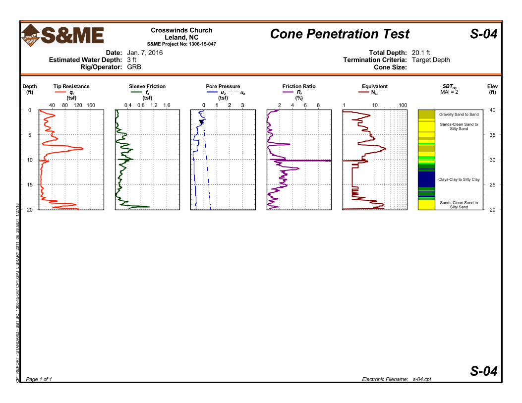
S&ME’s subcontract driller advanced six cone penetration test (CPT) soundings on January 7 and 26, 2016
in general accordance with the attached Field Testing Procedures. The approximate sounding locations
are shown on Figure II-2 in Appendix II. Since the soundings were located in the field by using a hand-
held GPS unit and approximating distances from stakes set by the project surveyors, their locations should
be considered approximate.
The soundings were advanced to depths ranging from approximately 20 to 60 feet beneath the existing
ground surface. In addition, the cone used for this exploration was instrumented with seismic sensors and
shear-wave velocities in Sounding S-02 at depth intervals of approximate 4 feet.
CPT sounding logs showing the soils encountered (based on soil behavior type) are attached in Appendix
IV. The ground surface elevations given on the CPT logs were estimated from Google EarthTM.
2.2 Hand Auger Borings
S&ME personnel advanced two hand auger borings (designated S-02 and S-03) to depths of 4.0 to 7.0
feet below the existing ground surface on December 17, 2015. The approximate boring locations are
shown in Figure II-2 in Appendix II. Since the borings were located in the field by our personnel by using
a hand-held GPS and approximating distances from stakes set by the project surveyors, their locations
should be considered approximate. The encountered soils were visually-manually classified in the field in
general accordance with the Unified Soil Classification System. At the completion of drilling operations,
the groundwater depths in the boreholes were measured. Hand auger boring logs are attached in
Appendix IV.
Reviewed For Code Compliance

Geotechnical Exploration Report
Crosswinds Church, Lanvale Road
Leland, North Carolina
S&ME Project No. 1306-15-047
January 27, 2016 3
3.0 Subsurface Conditions
3.1 Physiography and Area Geology
Figure 3-1 - Physiography
The site is located within the Coastal Plain Physiographic Province of North Carolina as shown in Figure 3-
1. The Coastal Plain Province is typically characterized by marine, alluvial, and aeolian sediments that were
deposited during periods of fluctuating sea levels and moving shorelines. The soils and basal formations
in the North Carolina Coastal Plain Physiographic Province are typical of those laid down in a shallow
sloping sea bottom; interbedded sands and clays with irregular deposits of shells and layers of limestone
and cemented sands. Alluvial sands, silts, and clays are typically present near rivers and creeks. Deposits
of peat, organic silt, and organic clay are also typically present in or near current or former tidal marsh
areas in the outer portion of the Coastal Plain.
3.2 Soil Survey
A map of the near-surface soils is given in Figure II-3 in Appendix II. The Soil Survey Report for Brunswick
County, North Carolina, (published by the United States Department of Agriculture Soil Conservation Service
in 1982) indicates that the proposed building area is underlain primarily by the soil series listed in the
following table. The following soil properties and characteristics are given in the Soil Survey Report for these
soils:
SITE
Reviewed For Code Compliance

Geotechnical Exploration Report
Crosswinds Church, Lanvale Road
Leland, North Carolina
S&ME Project No. 1306-15-047
January 27, 2016 4
Table 3-1 - Soil Survey Soil Properties
Soil Name
Typical
Depth
(inches)
Unified Soil
Classification
% Passing
No. 200
Sieve
Liquid
Limit
Plasticity
Index
High Water
Table
(feet)
Ly –
Lynchburg
0 – 16
6 – 80
SM, ML, SM-SC, CL-ML
SM-SC, SC, CL, CL-ML
25 – 55
25 – 67
< 30
15 – 40
NP -7
4 - 18
0.5 – 1.5
Apparent
Nov - Apr
NoA, NoB –
Norfolk
0 – 16
16 – 63
SM
SC, SM-SC, CL, CL-ML
13 – 30
30 – 63
< 20
20 – 38
NP
4 – 15
4.0 – 6.0
Apparent
Jan - Mar
3.3 Soundings and Borings
Subsurface conditions as indicated by the CPT soundings and hand auger borings generally consist of
topsoil over Coastal Plain soils. The generalized subsurface conditions at the site are described below.
For more detailed soil descriptions and stratifications at a particular location, the respective sounding or
boring log should be reviewed.
3.3.1 Surface Materials
The hand auger borings encountered topsoil (i.e., organic-laden soil) just below the ground surface.
Topsoil thicknesses were measured at 0.5 to 0.9 feet in the two hand auger borings.
3.3.2 Very Loose to Medium Dense Sand
Beneath the surface materials, very loose to medium dense sand was encountered to depths of 8 to 12
feet. CPT tip stress values ranged from approximately 10 to 120 tsf. The sand classified as silty sand (SM)
and clayey sand (SC) in the two hand auger borings.
3.3.3 Soft Clay
Beneath the very loose to medium dense sand stratum, soft clay was encountered to depths of 5 to 20
feet. CPT tip stress values ranged from approximately 5 to 10 tsf.
3.3.4 Medium Dense to Dense Sand
Beneath the soft clay stratum, medium dense sand was encountered to a depths of 60 feet. CPT tip stress
values ranged from approximately 80 to 200 tsf. The deepest sounding was terminated in this stratum at
a depth of 60 feet below the existing ground surface.
Reviewed For Code Compliance

Geotechnical Exploration Report
Crosswinds Church, Lanvale Road
Leland, North Carolina
S&ME Project No. 1306-15-047
January 27, 2016 5
3.3.5 Groundwater
Water levels were measured in the hand auger boreholes and estimated from the pore pressure
measurements made by the CPT soundings. The water levels varied from depths of approximately 2 to 5
feet below the existing ground surface, with an average depth of approximately 3 feet.
Groundwater levels have been measured or estimated in the CPT soundings at the times and under the
conditions stated on the logs in this report. Changes in the groundwater conditions and depths may
occur due to seasonal variations in rainfall, evaporation, construction activity, surface water runoff, and
other site specific factors.
4.0 Conclusions and Recommendations
4.1 Management of Shallow Groundwater
Based on the subsurface conditions indicated by the published soil survey and the field explorations, we
anticipate that relatively shallow groundwater could result in an unstable soil subgrade in the proposed
building area, especially during the wetter, cooler months of the year when seasonal high water table
conditions typically occur. Shallow groundwater can result in weakening of the building subgrades, and
consequent failure and/or loss of support in the building floor slab areas.
If site grades are raised at least 2 feet in the building area, we do not anticipate the need for permanent
dewatering measures, such as French drains. If design grades are between 1 to 2 feet above existing
grades, we recommend that the groundwater conditions be evaluated at the time of construction. If
shallow water is encountered during construction, temporary ditches or French drains should be installed
to remove the water. If design grades are lower than 1 foot above existing grades, we recommend that
permanent French drains be installed. We can provide additional recommendations for temporary and
permanent dewatering once a grading plan has been prepared and submitted for our review, and during
construction of the project if S&ME is retained to provide construction special inspections and materials
testing.
4.2 Site Preparation
Site preparation should be initiated by clearing, grubbing, and stripping the proposed construction areas
of any trees, shrubs, stumps, plants, topsoil, roots, organics, debris, trash, and other unsuitable material.
We anticipate an average stripping depth of 12 inches to remove the topsoil and rootmat across the
majority of the site. Excavations or cavities resulting from grubbing and demolition should be backfilled
with compacted structural backfill.
After clearing, grubbing, and stripping in proposed fill areas and after excavation to design subgrade
elevations in cut areas, we recommend that the exposed subgrade soils be proofrolled with a loaded
tandem-axle dump truck to locate any areas of soft or otherwise unsuitable surface conditions. Any area
that ruts or pumps should be disked, moisture conditioned to near the soil's optimum moisture content
by drying or wetting, and recompacted. Alternatively, unstable soils could be undercut and replaced with
compacted backfill. To decrease recommended undercut depths, geosynthetics such as woven geotextile
or geogrid could be used to achieve subgrade stability prior to structural fill placement.
Reviewed For Code Compliance

Geotechnical Exploration Report
Crosswinds Church, Lanvale Road
Leland, North Carolina
S&ME Project No. 1306-15-047
January 27, 2016 6
Based on the field explorations and our site observations, we anticipate potential undercutting of near-
surface soils in areas represented by S-03 and S-05, in addition to localized areas between and away from
the boring and sounding locations.
The total amount of undercutting will depend on the design grades and the weather conditions at the
time of proofrolling and site earthwork. It is typically more practical and economical to undercut and
replace soft, wet subgrades soils, rather than disk, dry, and re-compact them, especially during the
typically cooler, wetter months of the year (November through March).
Based on the geotechnical data and our experience with soils in this area, we recommend that the
construction contract include an allowance for the undercutting of unstable or unsuitable soils and
replacement with compacted structural fill. It could also include an allowance for the use of geotextiles, such
as a woven stabilization fabric (Mirafi 500X or equivalent).
Once the initial proofrolling and, if necessary, compaction or undercutting of the subgrade soils in the
building, pavement, and any other structural areas has been completed, the contractor should protect the
exposed soil subgrades by smooth-rolling and grading the site to promote surface water runoff. Exposure to
the environment and construction activities will likely weaken the exposed subgrade soils. If deterioration of
the soil occurs during the construction process due to the contractor’s failure to protect stable subgrades,
then disking and drying, re-compaction, densification, stabilization with geotextiles, and/or undercutting and
replacement with structural fill may be necessary, and should be performed by the contractor as
recommended by the geotechnical engineer’s representative.
4.3 Excavation Considerations
Temporary construction excavations 5 feet or more in depth that require entrance by personnel should be
sloped and/or temporarily shored. Also, temporary construction excavations below the groundwater level
at the time of construction should be dewatered.
4.3.1 Temporary Sloping and/or Shoring
Temporary construction slopes and excavation shoring should comply with local, state, and federal
governing regulations, including OSHA (29 CFR Part 1926) excavation trench safety standards. Temporary
excavations should be cut to a stable slope or the excavations should be temporarily braced, depending
upon the excavation depth, nearby site features, and encountered subsurface conditions. The
Contractor’s Competent Person will need to determine the soil type(s) encountered in excavations and the
appropriate excavation slope or bracing.
Stockpiles should be placed well away from the top edge of the excavations, and their heights should be
controlled so they do not surcharge the sides of the excavations. We recommend that stockpiles be set
back a minimum horizontal distance from the top edge of the excavation equal to the maximum depth of
the excavation.
The responsibility for excavation safety, stability of temporary construction excavations, and
deflections/settlement of existing site features lie solely with the contractor. This information is provided
only as a service and under no circumstance should S&ME be assumed to be responsible for constructionReviewed For Code Compliance

Geotechnical Exploration Report
Crosswinds Church, Lanvale Road
Leland, North Carolina
S&ME Project No. 1306-15-047
January 27, 2016 7
site safety, stability of temporary excavations, or the effectiveness of the contractor’s excavation support
system.
4.3.2 Construction Dewatering
Potential groundwater control methods for the temporary construction excavations include open
pumping. Open pumping utilizes submersible sump pumps in pits or trenches dug below the bottom of
the excavation and backfilled with No. 57 stone. Submersible sump pumps placed in perforated or slotted
plastic pipe installed in angled pits backfilled with No. 57 stone below the bottom of the excavation,
called “stingers”, are another type of open pumping. Pumping can be performed on an intermittent basis
to remove water from the construction excavation, but should be continuous (24 hours a day) to maintain
excavation bottom stability. Based on our experience with similar subsurface conditions and similar
projects in coastal North Carolina, we anticipate that open pumping will be necessary for temporary
foundation and utility construction excavations below the water table in the proposed building area.
The responsibility for dewatering of construction excavations should lie solely with the contractor. This
information is provided only as a service and under no circumstance should S&ME be assumed to be
responsible for the effectiveness of the construction dewatering method(s) selected by the contractor.
4.4 Structural Fill and Backfill
4.4.1 Placement and Compaction
Structural fill and structural backfill should be placed in building, slab, or other structural areas. Where
structural fill and structural backfill are required to reach finished grades, we recommend that a soil
having a Unified Soil Classification of GW, GP, GP-GM, GP-GC, GW-GM, GW-GC, GM, SW, SP, SP-SM, SP-
SC, SW-SM, SM, or SC be used. The satisfactory or unsatisfactory definition of the structural fill and
structural backfill materials should be based on soil classification determined by grain-size distribution
and plasticity, not by moisture content. Relatively dry or wet soils meeting the recommended
classifications can be used as structural fill and structural backfill, but may require wetting or drying to
achieve the recommended moisture content and compaction.
The structural fill and structural backfill should also be generally free of organics (less than 2% by weight
per ASTM D-2974) and free of deleterious materials. Pieces of inert debris, such as gravel, rock fragments,
brick and concrete, should be limited to no more than 3 inches in maximum dimension, and should be
blended with soil to prevent the formation of voids.
Structural fill and structural backfill should be placed in 10-inch maximum loose lifts in open site areas
(more than 10 feet wide and compacted with heavier equipment) and 6-inch maximum loose lifts in
trench areas (less than 10 feet wide and compacted with hand operated equipment). Structural fill and
structural backfill should be compacted to at least 95 percent of the standard Proctor maximum dry unit
weight (ASTM D-698) more than 12 inches below finish subgrade elevations. The upper 12 inches of
structural fill and structural backfill should be compacted to at least 98 percent of the material's standard
Proctor maximum dry unit weight. The moisture content of the material should be within +/- 3% of the
material’s standard Proctor optimum moisture content for most types of satisfactory soils. The
Reviewed For Code Compliance

Geotechnical Exploration Report
Crosswinds Church, Lanvale Road
Leland, North Carolina
S&ME Project No. 1306-15-047
January 27, 2016 8
acceptable moisture content range can be increased to +/- 5% for satisfactory sands and gravels with less
than 20% fines, provided the recommended compaction is still achieved.
Even though silty sand (SM) and clayey sand (SC) are satisfactory for use as compacted structural fill and
structural backfill, they are somewhat moisture sensitive and can be difficult to adequately dry and
compact, especially during the wetter, cooler times of the year. Even if the specified compaction is
achieved, the fill surface must be stable prior to placement of overlying lifts of fill, which can be difficult to
achieve for these somewhat moisture-sensitive soils.
To confirm that the specified degree of compaction is being obtained, field compaction testing should be
performed in each fill lift by the geotechnical engineer’s representative. We recommend that compaction
tests be performed at a minimum frequency of one test per 2,500 square feet per lift in building areas,
5,000 square feet in pavement areas, and one test per 100 linear feet per lift of utility trench backfill in
structural areas.
4.4.2 Use of On-Site Soil
The on-site soils meeting the classifications for recommended satisfactory structural fill and backfill, plus
meeting the restrictions on organic content and debris, may be used as structural fill and backfill. We
anticipate that the majority of sands encountered in the borings/soundings within the anticipated excavation
depths will be satisfactory for use as compacted structural fill and structural backfill. However, some lenses or
layers of unsatisfactory clay (CL) are anticipated in the upper 8 to 12 feet based on the Soil Survey Report.
The deeper soft clay stratum is unsuitable for use as structural fill and backfill.
On-site soils used as structural fill and structural backfill will require careful moisture control in order to
achieve compaction and stability. Any soils excavated from below the water table will require significant
drying to achieve the recommended moisture content and minimum compaction. Soils above the water table
may also be relatively dry at the time of construction and require wetting to achieve the recommended
moisture content and minimum compaction.
During excavation of on-site soils, the contractor should segregate satisfactory and unsatisfactory soils based
on their classifications and other recommended restrictions. Drier satisfactory soils (e.g., excavated from
above the water table) and wetter satisfactory soils (e.g., excavated from below the water table) should also
be segregated. The wetter soils may require spreading, disking, and drying. However, during the typically
cooler, wetter months of the year (typically November through March), it may be more economical to import
satisfactory soils from off site, rather than to attempt to dry and re-use wet to saturated on-site soils.
The use of on-site satisfactory soils, use of imported off-site soils, wasting of on-site soils, and quantities
required are subject to the project design grades and the contractor’s means and methods. These issues
should be accounted for by the contractor during the bid phase of the project. The use of imported off-site
soils to replace on-site satisfactory soils which may be excessively dry or excessively wet at the time of
construction is acceptable, but if chosen by the contractor, should be included in the contractor’s pricing for
the project.
Reviewed For Code Compliance

Geotechnical Exploration Report
Crosswinds Church, Lanvale Road
Leland, North Carolina
S&ME Project No. 1306-15-047
January 27, 2016 9
4.5 Seismic Design
4.5.1 General
There are no known, mapped faults in the area of the site. Five minor earthquakes with epicenters in the
Wilmington area with magnitudes of 3.0 to 3.9 occurred between 1871 and 19681. The historic
earthquake event which influences the design seismicity of the site the most is the 1886 Charleston, South
Carolina earthquake with a magnitude of approximately 7.3.
4.5.2 Seismic Site Class
Based on the shear wave velocities measured by the seismic CPT sounding (S-02), a Seismic Site Class D
designation is appropriate for seismic design in accordance with Section 1613 of the 2012 North Carolina
Building Code.
4.5.3 Ground Motion Parameters
We recommend that the project be designed using the ground motion parameters given in the following
table:
Table 4-1 – Ground Motion Parameters
Method
Site
Class SS S1 SDS SD1 PGA
Seismic
Design
Category
2012 North
Carolina Building
Code
D 0.31 g 0.10 g 0.32 g 0.16 g 0.13 g C (for OC I-III)
4.5.4 Liquefaction Evaluation
We performed a seismic liquefaction triggering evaluation using the method presented by Youd et. al.
(2001)2 and Boulanger and Idriss (2014)3 based on the design earthquake (M=7.3). The design earthquake
has a 2 percent probability of exceedance in a 50 year period. This is equivalent to an earthquake that has
the likelihood of occurring once every 2,475 years. Using the 2012 North Carolina Building Code (which is
based on the 2009 International Building Code), the design seismic event has a peak ground acceleration
(pga) of 0.13 g at this site. This value was calculated using Seismic Site Class D, calculating the five-
percent damped spectral response aacceleration at short periods, SDS, using the USGS website tool for U.S.
Seismic Design Maps, and dividing SDS by 2.5 per Section 1803.5.12 (2) of the 2012 North Carolina
Building Code. Based on the results of our analyses, we conclude that the site has a low liquefaction
1 Map of Earthquake Epicenters in North Carolina and Portions of Adjacent States (1698-2006), North Carolina Geologic Survey.2 Youd. T.L. et. al. (2001), “Liquefaction Resistance of Soils: Summary Report From the 1996 NCEER and 1998 NCEER/NSF Workshops
on Evaluation of Liquefaction Resistance of Soils”, J. Geotech. Geoenviron. Eng., 127(10), 817-833.3 Boulanger, R.W. and Idriss, I.M. (2014), CPT and SPT Based Liquefaction Triggering Procedures, Report No. UCD/CGM-14/01, Center
for Geotechnical Modeling, Department of Civil and Environmental Engineering, University of California, Davis, CA. Reviewed For Code Compliance

Geotechnical Exploration Report
Crosswinds Church, Lanvale Road
Leland, North Carolina
S&ME Project No. 1306-15-047
January 27, 2016 10
potential for the design earthquake, and no further consideration of liquefaction is necessary for the
design of the project.
4.6 Foundations
The proposed building can be supported on shallow spread footings. The footings should bear on sufficiently
stiff and strong natural soils or properly compacted structural fill.
If the Allowable Stress Design (ASD) method is used to estimate design foundation loads, footings can be
sized using a net allowable bearing pressure of 1,500 pounds per square foot (psf) and unfactored loads.
Since this value is a net bearing pressure, the weight of the footing concrete and any soil backfill above
the footing can be ignored when sizing the footings.
For this site and the proposed structure, we estimate the total settlement for the footings will be less than
1 inch, which is typically tolerable by structures similar to that proposed. If precautions are taken to avoid
dissimilar bearing conditions between consecutive foundations along column lines, differential settlement
between consecutive column footings (at least 20 feet apart) and along wall footings should also be
tolerable (less than about ½-inch between any two points approximately 20 to 30 feet apart).
Shallow foundations should be designed to bear at least 12 inches below finished grades for frost pro-
tection and protective embedment. In accordance with the North Carolina Building Code, column
footings should be at least 24 inches square and wall footings should be at least 16 inches wide to
prevent a punching shear failure of the foundation bearing soils. Turndown slabs should be at least 12
inches wide under walls in accordance with the North Carolina Building Code.
Footing excavations should be observed, probed, and tested (shallow hand auger borings with Dynamic Cone
Penetrometer tests) by the geotechnical engineer's representative to verify that suitable foundation bearing
materials are present at, and below, the proposed bearing elevation. If unsuitable foundation bearing
materials (e.g., very soft soil, very loose soil, excessively compressible soil, unstable soil, and deleterious
materials) are present below the bottom of the footing excavations, they should be excavated, removed, and
replaced (i.e., undercut) with concrete, flowable fill, or compacted structural fill. Washed crushed stone (e.g.,
No. 57 stone) should not be used unless it is wrapped in a non-woven filter fabric (Mirafi 140N or equivalent).
Relatively thin zones of very loose sand (SP, SP-SM) at the footing bearing elevation can typically be densified
in place using a jumping jack compactor or vibratory plate tamp.
Based on the hand auger borings and CPT soundings, we anticipate that undercutting of foundation bearing
soils will be required in the areas represented by CPT Soundings S-03 and S-05 to remove zones of very loose
silty sand and clayey sand. Also, localized undercutting of footings between and away from the hand auger
and CPT sounding locations may be necessary.
Prepared bearing surfaces for foundations should not be disturbed or left exposed during inclement weather.
Saturation of the footing subgrade can cause a loss of strength and increased compressibility. If construction
occurs during inclement weather and concreting of foundations is not possible at the time they are excavated,
the footing bearing conditions should be re-evaluated after removal of any water and wet, softened soils
prior to placement of reinforcing steel and concrete. Also, concrete should not be placed on frozen
subgrades.Reviewed For Code Compliance

Geotechnical Exploration Report
Crosswinds Church, Lanvale Road
Leland, North Carolina
S&ME Project No. 1306-15-047
January 27, 2016 11
4.7 Ground Floor Slabs
The building’s ground floor can be a concrete slab-on-grade. The slab-on-grade ground floor should be
constructed above satisfactory and stable existing soils or compacted structural fill. After site grading, we
anticipate that the majority of the near-surface soils in the proposed building areas will be silty sand (SM)
or clayey sand (SC). A modulus of subgrade reaction value of 140 psi/in may be used to design floor slabs
subjected to point loads and bearing on subgrades consisting of these soils compacted to at least 98 percent
of the soil’s standard Proctor maximum dry density.
We recommend that at least 6 inches of compacted select granular material be placed beneath all ground
floor slabs to provide a capillary break, provide more uniform slab support, and reduce damage to subgrade
soils during construction. The select granular fill should classify as SP, SP-SM, SW, or SW-SM in accordance
with the Unified Soil Classification System, which requires that these soils have less than 12 percent passing
the No. 200 sieve. Manufactured materials such as aggregate base course (ABC) or processed fill (i.e.,
screenings) meeting this specification can be used.
Based on the results of our exploration and our assumptions, the floor slab will not be below the exterior
grade and will not be subjected to hydrostatic pressure from groundwater. However, water vapor
transmission through the slab is still a design consideration. Evaluating the need for and design of a
vapor retarder or vapor barrier for moisture control is outside our scope of services and should be
determined by the project architect/structural engineer based on the planned floor coverings and the
corresponding design constraints, as outlined in ACI 302.1R-04 Guide for Concrete Floor and Slab
Construction. Further, health and environmental considerations with respect to any potentially harmful
vapor transmission are also outside of our scope.
5.0 Limitations of Geotechnical Report
This report has been prepared in accordance with generally accepted geotechnical engineering practice
for specific application to this project. The conclusions and recommendations contained in this report are
based upon applicable standards of our practice in this geographic area at the time this report was
prepared. No other representation or warranty either express or implied, is made.
We relied on project information given to us to develop our conclusions and recommendations. If project
information described in this report is not accurate, or if it changes during project development, we
should be notified of the changes so that we can modify our recommendations based on this additional
information if necessary.
Our conclusions and recommendations are based on limited data from a field exploration program.
Subsurface conditions can vary widely between explored areas. Some variations may not become evident
until construction. If conditions are encountered which appear different than those described in our
report, we should be notified. This report should not be construed to represent subsurface conditions for
the entire site.
Unless specifically noted otherwise, our field exploration program did not include an assessment of
regulatory compliance, environmental conditions or pollutants or presence of any biological materials
Reviewed For Code Compliance

Geotechnical Exploration Report
Crosswinds Church, Lanvale Road
Leland, North Carolina
S&ME Project No. 1306-15-047
January 27, 2016 12
(mold, fungi, bacteria). If there is a concern about these items, other studies should be performed. S&ME
can provide a proposal and perform these services if requested.
S&ME should be provided the opportunity to review the final plans and specifications to confirm that
earthwork, foundation, and other recommendations are properly interpreted and implemented. The
recommendations in this report are contingent on S&ME’s review of final plans and specifications
followed by observation and monitoring of earthwork and foundation construction activities.
Reviewed For Code Compliance

Appendices
Reviewed For Code Compliance

Appendix I – Important Information about Your Geotechnical
Report
Reviewed For Code Compliance

Appendix II – Additional Figures
Reviewed For Code Compliance

Appendix III – Field Testing Procedures and Legends
Reviewed For Code Compliance

Appendix IV – Exploration Logs
Reviewed For Code Compliance

Portion obtained with permission from “Important Information About Your Geotechnical Engineering Report”, ASFE, 2004 © S&ME, Inc. 2010
Important Information About Your
Geotechnical Engineering Report
Variations in subsurface conditions can be a principal cause of construction delays, cost overruns and claims. The following information is provided to assist you in understanding and managing the risk of these variations.
Geotechnical Findings Are Professional Opinions Geotechnical engineers cannot specify material properties as other design engineers do. Geotechnical material properties have a far broader range on a given site than any manufactured construction material, and some geotechnical material properties may change over time because of exposure to air and water, or human activity. Site exploration identifies subsurface conditions at the time of exploration and only at the points where subsurface tests are performed or samples obtained. Geotechnical engineers review field and laboratory data and then apply their judgment to render professional opinions about site subsurface conditions. Their recommendations rely upon these professional opinions. Variations in the vertical and lateral extent of subsurface materials may be encountered during construction that significantly impact construction schedules, methods and material volumes. While higher levels of subsurface exploration can mitigate the risk of encountering unanticipated subsurface conditions, no level of subsurface exploration can eliminate this risk.
Scope of Geotechnical Services Professional geotechnical engineering judgment is required to develop a geotechnical exploration scope to obtain information necessary to support design and construction. A number of unique project factors are considered in developing the scope of geotechnical services, such as the exploration objective; the location, type, size and weight of the proposed structure; proposed site grades and improvements; the construction schedule and sequence; and the site geology. Geotechnical engineers apply their experience with construction methods, subsurface conditions and exploration methods to develop the exploration scope. The scope of each exploration is unique based on available project and site information. Incomplete project information or constraints on the scope of exploration increases the risk of variations in subsurface conditions not being identified and addressed in the geotechnical report.
Services Are Performed for Specific Projects Because the scope of each geotechnical exploration is unique, each geotechnical report is unique. Subsurface conditions are explored and recommendations are made for a specific project. Subsurface information and recommendations may not be adequate for other uses. Changes in a proposed structure location, foundation loads, grades, schedule, etc. may require additional geotechnical exploration, analyses, and consultation. The geotechnical engineer should be consulted to determine if additional services are required in response to changes in proposed construction, location, loads, grades, schedule, etc. Geo-Environmental Issues The equipment, techniques, and personnel used to perform a geo-environmental study differ significantly from those used for a geotechnical exploration. Indications of environmental contamination may be encountered incidental to performance of a geotechnical exploration but go unrecognized. Determination of the presence, type or extent of environmental contamination is beyond the scope of a geotechnical exploration. Geotechnical Recommendations Are Not Final Recommendations are developed based on the geotechnical engineer’s understanding of the proposed construction and professional opinion of site subsurface conditions. Observations and tests must be performed during construction to confirm subsurface conditions exposed by construction excavations are consistent with those assumed in development of recommendations. It is advisable to retain the geotechnical engineer that performed the exploration and developed the geotechnical recommendations to conduct tests and observations during construction. This may reduce the risk that variations in subsurface conditions will not be addressed as recommended in the geotechnical report.
Reviewed For Code Compliance

SCALE:
DRAWN BY:
DATE: S&ME PROJECT NUMBER:
NOT TO SCALE
CHECKED BY: KCB
FIGURENUMBER
TMS
1306-15-0471/25/2016
SITE LOCATION PLANCROSSWIND CHURCH, LANVALE ROAD
LELAND, NORTH CAROLINA
SITE
Note: Drawing obtainedfrom Delorme Street AtlasUSA® 2013
II-1
Reviewed For Code Compliance

SCALE:
PREPARED BY:
DATE:
CHECKED BY:
FIGURE
NUMBER
KCB
TMS
1/27/2016
FIELD TEST LOCATION PLAN
CROSSWIND CHURCH, LANVALE ROAD
LELAND, NORTH CAROLINA
S&ME PROJECT NUMBER: 1306-15-047
LEGEND
S&ME CPT Soundings Advanced 1/7/2016.REFERENCE: SITE PLAN PREPARED BY H.
BURKERT & CO. DATED 8/18/2015S&ME CPT Soundings Advanced 1/26/2016.
S&ME Hand Auger Borings Advanced 12/17/2015.
II-2
NOT TO SCALE
S-04
S-03S-02
S-01
S-06S-05
Reviewed For Code Compliance

SCALE:
PREPARED BY:
DATE:
NOT TO SCALE
CHECKED BY:
FIGURENUMBER
KCB
TMS
1/23/2016
SOILS MAPCROSSWIND CHURCH, LANVALE ROAD
LELAND, NORTH CAROLINA
S&ME PROJECT NUMBER: 1306-15-047
II-3
REFERENCE: UNITED STATES DEPARTMENT OFAGRICULTURE WEB SOIL SURVEY WEBSITE,www.websoilsurvey.sc.egov.usda.gov
SITE

FIELD TESTING PROCEDURES
Soil Test Borings
All boring and sampling operations were conducted in accordance with ASTM Designation D-1586. Initially, the borings were advanced by either mechanically augering or wash boring through the soils.
Where necessary, a heavy drilling fluid is used below the water table to stabilize the side and bottom of
the drill hole. At regular intervals soil samples were obtained with a standard 1.4-inch I.D., 2-inch O.D., split-barrel sampler. The sampler was first seated 6 inches to penetrate any loose cuttings and then driven
an additional foot with blows of a 140 pound hammer falling 30 inches. The number of hammer blows
required to drive the sampler the final foot is designated the "Standard Penetration Resistance." The
penetration resistance, when properly evaluated, is an index to the soil strength.
Soil Classifications
Soil classifications provide a general guide to the engineering properties of various soil types and enable
the engineer to apply his past experience to current problems. In our exploration, samples obtained
during drilling operations are examined and visually classified according to color, texture, and relative density or consistency (based on standard penetration resistance). The consistency and relative density
designations are as follows:
SANDS SILTS AND CLAYS
N (SPT) Relative Density N (SPT) Consistency
0 - 4 Very Loose 0 - 2 Very Soft
5 - 10 Loose 3 - 4 Soft
5 - 8 Firm 11 - 30 Medium Dense
9 - 15 Stiff
31 - 50 Dense 16 - 30 Very Stiff
31 - 50 Hard 50+ Very Dense
50+ Very Hard
Reviewed For Code Compliance
Reviewed For Code Compliance

Silty Sand
Clayey Sand
Sandy Silt
HC
LEGEND TO SOIL CLASSIFICATION AND SYMBOLS
Silty Clay
Partially WeatheredRock
Cored Rock
(Shown in Water Level Column)
- Total Length of Rock Recovered in the CoreBarrel Divided by the Total Length of the CoreRun Times 100%.
- Total Length of Sound Rock SegmentsRecovered that are Longer Than or Equal to 4"(mechanical breaks excluded) Divided by theTotal Length of the Core Run Times 100%.
0 to 45 to 1011 to 3031 to 50Over 50
SOIL TYPES
RELATIVE DENSITY
Very LooseLoose
Medium DenseDense
Very Dense
SAMPLER TYPES(Shown in Samples Column)
TERMS
StandardPenetrationResistance
Clayey Silt
Sandy Clay
(Shown in Graphic Log)
WATER LEVELS
CONSISTENCY OF COHESIVE SOILS
CONSISTENCY
RQD
Asphalt
Concrete
Topsoil
Gravel
Sand
Silt
STD. PENETRATIONRESISTANCEBLOWS/FOOT
Very SoftSoftFirmStiff
Very StiffHard
Very Hard
REC
Clay
Organic
STD. PENETRATIONRESISTANCEBLOWS/FOOT
RELATIVE DENSITY OF COHESIONLESS SOILS
= Water Level At Termination of Boring= Water Level Taken After 24 Hours= Loss of Drilling Water= Hole Cave
- The Number of Blows of 140 lb. Hammer Falling30 in. Required to Drive 1.4 in. I.D. Split SpoonSampler 1 Foot. As Specified in ASTM D-1586.
0 to 23 to 45 to 89 to 1516 to 3031 to 50Over 50
Fill
Split Spoon
Rock Core
No Recovery
Reviewed For Code Compliance

FIELD TESTING PROCEDURES Cone Penetrometer Test (CPT) Sounding The cone penetrometer test soundings (ASTM D 5778) were performed by hydraulically pushing an electronically instrumented cone penetrometer through the soil at a constant rate. As the cone penetrometer tip was advanced through the soil, nearly continuous readings of point stress, sleeve friction and pore water pressure were recorded and stored in the on-site computers. Using theoretical and empirical relationships, CPT data can be used to determine soil stratigraphy and estimate soil properties and parameters such as effective stress, friction angle, Young’s Modulus and undrained shear strength. The consistency and relative density designations, which are based on the cone tip resistance, qt for sands and cohesive soils (silts and clays) are as follows:
SANDS SILTS AND CLAYS
Cone Tip Resistance, qt (tsf)
Relative Density Cone Tip Resistance, qt (tsf)
Consistency
<20 Very Loose <5 Very Soft
20 – 40 Loose 5 – 10 Soft
10 – 15 Firm 40 – 120 Medium Dense
15 – 30 Stiff
120 – 200 Dense 30 –60 Very Stiff
>200 Very Dense >60 Hard CPT Correlations References are in parenthesis next to the appropriate equation. General pa = atmospheric pressure (for unit normalization) qt = corrected cone tip resistance (tsf) fs = friction sleeve resistance (tsf) Rf = 100% * (fs/qt) u2 = pore pressure behind cone tip (tsf) u0 = hydrostatic pressure Bq = (u2-u0)/(qt-σv0) Qt = (qt-σv0)/ σ’v0 Fr = 100% * fs/(qt- σv0) Ic = ((3.47-logQt)2+(logFr+1.22)2)0.5 N-Value N60 = (qt/pa)/[8.5(1-Ic/4.6)] (6) (6) Jefferies, M.G. and Davies, M.P., (1993), “Use of CPTu to estimate equivalent SPT N60”, ASTM Geotechnical Testing Journal, Vol. 16, No. 4 Reviewed For Code Compliance

Min Max12 3.60 N/A3 2.95 3.604 2.60 2.955 2.05 2.606 1.31 2.057 N/A 1.318 Very stiff sand to clayey sand (High OCR or cemented)9
CPT Soil Classification Legend
Robertson's Soil Behavior Type (SBT), 1990
Group # Description Ic
Sensitive, fine grained N/AOrganic soils - peatsClays - silty clay to claySilt mixtures - clayey silt to silty claySand mixtures - silty sand to sandy siltSands - clean sand to silty sandGravelly sand to dense sand
N/AVery stiff, fine grained (High OCR or cemented) N/A
Soil behavior type is based on empirical data and may not be representative of soil classification based on plasticity and grain size distribution.
Relative Density and Consistency TableSANDS SILTS and CLAYS
Cone Tip Stress, qt (tsf) Relative Density Cone Tip Stress, qt (tsf) ConsistencyLess than 20 Very Loose Less than 5 Very Soft
20 - 40 Loose 5 - 15 Soft to Firm40 - 120 Medium Dense 15 - 30 Stiff120 - 200 Dense 30 - 60 Very Stiff
Greater than 200 Very Dense Greater than 60 Hard
Reviewed For Code Compliance

Gravelly Sand to Sand
Sands-Clean Sand toSilty Sand
Silt Mixtures-Clay Silt toSilty Clay
Electronic Filename: s-01.cpt
Depth(ft)
0
5
10
15
20
Tip Resistanceqt
(tsf)
40 80 120 160
5 ftCone Size:
Sleeve Frictionfs
(tsf)
0.4 0.8 1.2 1.6 0 1 2 3
Pore Pressureu2
(tsf)
0 1 2 3
u0
Friction RatioRf
(%)
2 4 6 8
SBTBq
MAI = 2
CP
T R
EP
OR
T -
ST
AN
DA
RD
- S
BT
BQ
130
6-15
-047
CP
T.G
PJ
LIB
RA
RY
201
1_0
6_2
8.G
DT
1/2
7/1
6
Jan. 7, 2016
GRB
Total Depth:Termination Criteria:
Date:Estimated Water Depth:
Rig/Operator:
Page 1 of 1
S&ME Project No: 1306-15-047
Crosswinds ChurchLeland, NC
S-01
20.1 ftTarget Depth
Elev(ft)
40
35
30
25
20
101 100
EquivalentN60
Cone Penetration Test S-01
Reviewed For Code Compliance

Gravelly Sand to Sand
Sands-Clean Sand toSilty Sand
Sands-Clean Sand toSilty Sand
Sand Mixtures-Silty Sandto Sandy Silt
Clays-Clay to Silty Clay
Sands-Clean Sand toSilty Sand
Sands-Clean Sand toSilty Sand
Sands-Clean Sand toSilty Sand
Gravelly Sand to Sand
Sands-Clean Sand toSilty Sand
Sands-Clean Sand toSilty Sand
Electronic Filename: s-02.cpt
Depth(ft)
0
5
10
15
20
25
30
35
40
45
50
Tip Resistanceqt
(tsf)
40 80 120 160
5 ftCone Size:
Sleeve Frictionfs
(tsf)
0.4 0.8 1.2 1.6 0 1 2 3
Pore Pressureu2
(tsf)
0 1 2 3
u0
Friction RatioRf
(%)
2 4 6 8
SBTBq
MAI = 2
CP
T R
EP
OR
T -
ST
AN
DA
RD
- S
BT
BQ
130
6-15
-047
CP
T.G
PJ
LIB
RA
RY
201
1_0
6_2
8.G
DT
1/2
7/1
6
Jan. 7, 2016
GRB
Total Depth:Termination Criteria:
Date:Estimated Water Depth:
Rig/Operator:
Page 1 of 2
S&ME Project No: 1306-15-047
Crosswinds ChurchLeland, NC
S-02
60.0 ftTarget Depth
Elev(ft)
40
35
30
25
20
15
10
5
0
-5
101 100
EquivalentN60
>>>>>>>>>>>>>>>>>>>>>>>>
>>>>>>>>>>>>>>>>
>>>>>>>>>>>>>>>>>>>>>>>>>>>>>>>>>>>>>>>>>>>>>>>>>>
>>>>>>>>
>>>>
Cone Penetration Test S-02
Reviewed For Code Compliance

Sand Mixtures-Silty Sandto Sandy Silt
Sands-Clean Sand toSilty Sand
Electronic Filename: s-02.cpt
Depth(ft)
50
55
60
Tip Resistanceqt
(tsf)
40 80 120 160
5 ftCone Size:
Sleeve Frictionfs
(tsf)
0.4 0.8 1.2 1.6 0 1 2 3
Pore Pressureu2
(tsf)
0 1 2 3
u0
Friction RatioRf
(%)
2 4 6 8
SBTBq
MAI = 2
CP
T R
EP
OR
T -
ST
AN
DA
RD
- S
BT
BQ
130
6-15
-047
CP
T.G
PJ
LIB
RA
RY
201
1_0
6_2
8.G
DT
1/2
7/1
6
Jan. 7, 2016
GRB
Total Depth:Termination Criteria:
Date:Estimated Water Depth:
Rig/Operator:
Page 2 of 2
S&ME Project No: 1306-15-047
Crosswinds ChurchLeland, NC
S-02
60.0 ftTarget Depth
Elev(ft)
-10
-15
101 100
EquivalentN60
>>>>>>>>
Cone Penetration Test S-02
Reviewed For Code Compliance

Sands-Clean Sand toSilty Sand
Gravelly Sand to Sand
Clays-Clay to Silty Clay
Electronic Filename: s-03.cpt
Depth(ft)
0
5
10
15
20
Tip Resistanceqt
(tsf)
40 80 120 160
3 ftCone Size:
Sleeve Frictionfs
(tsf)
0.4 0.8 1.2 1.6 0 1 2 3
Pore Pressureu2
(tsf)
0 1 2 3
u0
Friction RatioRf
(%)
2 4 6 8
SBTBq
MAI = 2
CP
T R
EP
OR
T -
ST
AN
DA
RD
- S
BT
BQ
130
6-15
-047
CP
T.G
PJ
LIB
RA
RY
201
1_0
6_2
8.G
DT
1/2
7/1
6
Jan. 7, 2016
GRB
Total Depth:Termination Criteria:
Date:Estimated Water Depth:
Rig/Operator:
Page 1 of 1
S&ME Project No: 1306-15-047
Crosswinds ChurchLeland, NC
S-03
20.1 ftTarget Depth
Elev(ft)
40
35
30
25
20
101 100
EquivalentN60
>>>>>>>>>>>>>>
Cone Penetration Test S-03
Reviewed For Code Compliance
Gravelly Sand to Sand
Sands-Clean Sand toSilty Sand
Clays-Clay to Silty Clay
Sands-Clean Sand toSilty Sand
Electronic Filename: s-04.cpt
Depth(ft)
0
5
10
15
20
Tip Resistanceqt
(tsf)
40 80 120 160
3 ftCone Size:
Sleeve Frictionfs
(tsf)
0.4 0.8 1.2 1.6 0 1 2 3
Pore Pressureu2
(tsf)
0 1 2 3
u0
Friction RatioRf
(%)
2 4 6 8
SBTBq
MAI = 2
CP
T R
EP
OR
T -
ST
AN
DA
RD
- S
BT
BQ
130
6-15
-047
CP
T.G
PJ
LIB
RA
RY
201
1_0
6_2
8.G
DT
1/2
7/1
6
Jan. 7, 2016
GRB
Total Depth:Termination Criteria:
Date:Estimated Water Depth:
Rig/Operator:
Page 1 of 1
S&ME Project No: 1306-15-047
Crosswinds ChurchLeland, NC
S-04
20.1 ftTarget Depth
Elev(ft)
40
35
30
25
20
101 100
EquivalentN60
>>
Cone Penetration Test S-04
Reviewed For Code Compliance

Sands-Clean Sand toSilty Sand
Sands-Clean Sand toSilty Sand
Gravelly Sand to Sand
Sand Mixtures-Silty Sandto Sandy Silt
Gravelly Sand to Sand
Electronic Filename: s-05.cpt
Depth(ft)
0
5
10
15
20
Tip Resistanceqt
(tsf)
40 80 120 160
2 ftCone Size:
Sleeve Frictionfs
(tsf)
0.4 0.8 1.2 1.6 0 1 2 3
Pore Pressureu2
(tsf)
0 1 2 3
u0
Friction RatioRf
(%)
2 4 6 8
SBTBq
MAI = 2
CP
T R
EP
OR
T -
ST
AN
DA
RD
- S
BT
BQ
130
6-15
-047
CP
T.G
PJ
LIB
RA
RY
201
1_0
6_2
8.G
DT
1/2
7/1
6
Jan. 26, 2016
GRB
Total Depth:Termination Criteria:
Date:Estimated Water Depth:
Rig/Operator:
Page 1 of 1
S&ME Project No: 1306-15-047
Crosswinds ChurchLeland, NC
S-05
20.1 ft
Elev(ft)
40
35
30
25
20
101 100
EquivalentN60
>>>>>>>>>>>>>>>>>>>>>>
Cone Penetration Test S-05
Reviewed For Code Compliance

Gravelly Sand to Sand
Sands-Clean Sand toSilty Sand
Sand Mixtures-Silty Sandto Sandy Silt
Clays-Clay to Silty Clay
Sands-Clean Sand toSilty Sand
Electronic Filename: s-06.cpt
Depth(ft)
0
5
10
15
20
Tip Resistanceqt
(tsf)
40 80 120 160
2 ftCone Size:
Sleeve Frictionfs
(tsf)
0.4 0.8 1.2 1.6 0 1 2 3
Pore Pressureu2
(tsf)
0 1 2 3
u0
Friction RatioRf
(%)
2 4 6 8
SBTBq
MAI = 2
CP
T R
EP
OR
T -
ST
AN
DA
RD
- S
BT
BQ
130
6-15
-047
CP
T.G
PJ
LIB
RA
RY
201
1_0
6_2
8.G
DT
1/2
7/1
6
Jan. 26, 2016
GRB
Total Depth:Termination Criteria:
Date:Estimated Water Depth:
Rig/Operator:
Page 1 of 1
S&ME Project No: 1306-15-047
Crosswinds ChurchLeland, NC
S-06
20.1 ft
Elev(ft)
40
35
30
25
20
101 100
EquivalentN60
Cone Penetration Test S-06
Reviewed For Code Compliance

TOPSOIL (SM)black to dark gray, silty sand, with organics, moist
SILTY SAND (SM)light gray and light brown, moist to wet
SILTY SAND (SM)gray, moist
SILTY SAND (SM)light gray, with clay lenses, saturated
Boring terminated at 7 ft
HAND AUGER BORING LOG: S-02
DATE FINISHED:
1306-15-047
DATE STARTED:
Leland, NC
12/17/15 12/17/15
T. Schipporeit
4.8 feet on 12/17/15
Cuttings
WATER LEVEL:
Crosswinds Church
SAMPLING METHOD:
PROJECT:
PERFORMED BY:
NOTES:
Page 1 of 1
GR
AP
HIC
LOG
Dep
th(f
eet)
1
2
3
4
5
6
7
WA
TE
RLE
VE
L
ELE
VA
TIO
N(f
eet)
40.00
39.00
38.00
37.00
36.00
35.00
34.00
MATERIAL DESCRIPTION
Reviewed For Code Compliance

TOPSOIL (SM)dark gray, silty sand, with organics, wet
SILTY SAND (SM)light gray and light brown, moist to wet
CLAYEY SAND (SC)gray and yellowish brown, saturated
Boring terminated at 4 ft
HAND AUGER BORING LOG: S-03
DATE FINISHED:
1306-15-047
DATE STARTED:
Leland, NC
12/17/15 12/17/15
T. Schipporeit
2.8 feet on 12/17/15
Cuttings
WATER LEVEL:
Crosswinds Church
SAMPLING METHOD:
PROJECT:
PERFORMED BY:
NOTES:
Page 1 of 1
GR
AP
HIC
LOG
Dep
th(f
eet)
1
2
3
4
WA
TE
RLE
VE
L
ELE
VA
TIO
N(f
eet)
39.00
38.00
37.00
36.00
MATERIAL DESCRIPTION
Reviewed For Code Compliance