geothermal power plant excellence
DESCRIPTION
best mhi productTRANSCRIPT

© 2012 MITSUBISHI HEAVY INDUSTRIES, LTD. All Rights Reserved.
Mitsubishi Geothermal Power Plant
December, 2012

© 2012 MITSUBISHI HEAVY INDUSTRIES, LTD. All Rights Reserved. 2
CONTENTS
1. Supply Record
2. What we can do for you
3. Technologies for higher performance and reliabilities
5. Collaboration with PEI

© 2012 MITSUBISHI HEAVY INDUSTRIES, LTD. All Rights Reserved. 3
1. Supply Record

4
Iceland 15-Units 565 MW
Greece 1-Unit 2 MW
Turkey 2-Unit
94.8 MW
Kenya 6-Units
149.8 MW
Indonesia 6-Units
386.3 MW
Phillipine 19-Units
702.7 MW
New Zealand 3-Units 113 MW
Costa Rica 2-Units 32 MW
El Salvador 3-Units
61.1 MW
Mexico 12-Units 210 MW
USA 18-Units 511.5 MW Japan
14-Units 272.3 MW
Portugal 1-Unit 3 MW
Total Output 3,103 MW Total Unit 102 Units Coped with Different Steam & Brine in 13 Countries
Supply Record of Mitsubishi Geothermal Power Plant
© 2012 MITSUBISHI HEAVY INDUSTRIES, LTD. All Rights Reserved.
As of 2012 December
© 2012 MITSUBISHI HEAVY INDUSTRIES, LTD. All Rights Reserved. 5
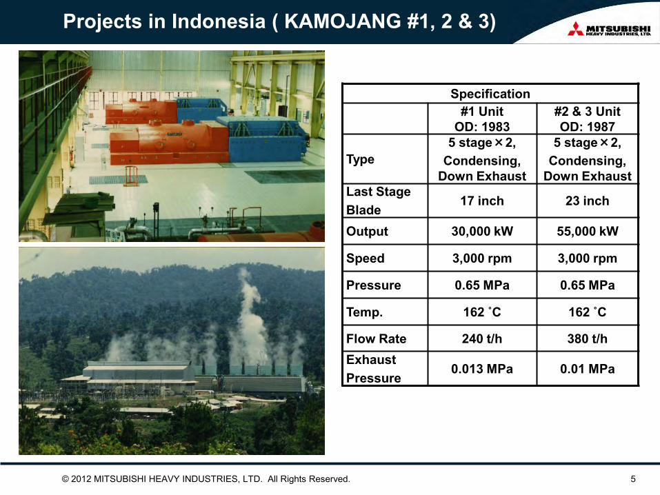
Projects in Indonesia ( KAMOJANG #1, 2 & 3)
Specification #1 Unit
OD: 1983 #2 & 3 Unit OD: 1987
Type 5 stage×2,
Condensing, Down Exhaust
5 stage×2, Condensing,
Down Exhaust Last Stage Blade
17 inch 23 inch
Output 30,000 kW 55,000 kW
Speed 3,000 rpm 3,000 rpm
Pressure 0.65 MPa 0.65 MPa
Temp. 162 ˚C 162 ˚C
Flow Rate 240 t/h 380 t/h Exhaust Pressure
0.013 MPa 0.01 MPa
© 2012 MITSUBISHI HEAVY INDUSTRIES, LTD. All Rights Reserved. 6
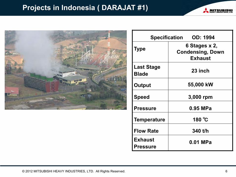
Projects in Indonesia ( DARAJAT #1)
Specification OD: 1994
Type 6 Stages x 2, Condensing, Down
Exhaust Last Stage Blade 23 inch
Output 55,000 kW
Speed 3,000 rpm
Pressure 0.95 MPa
Temperature 180 ℃
Flow Rate 340 t/h Exhaust Pressure
0.01 MPa
© 2012 MITSUBISHI HEAVY INDUSTRIES, LTD. All Rights Reserved. 7
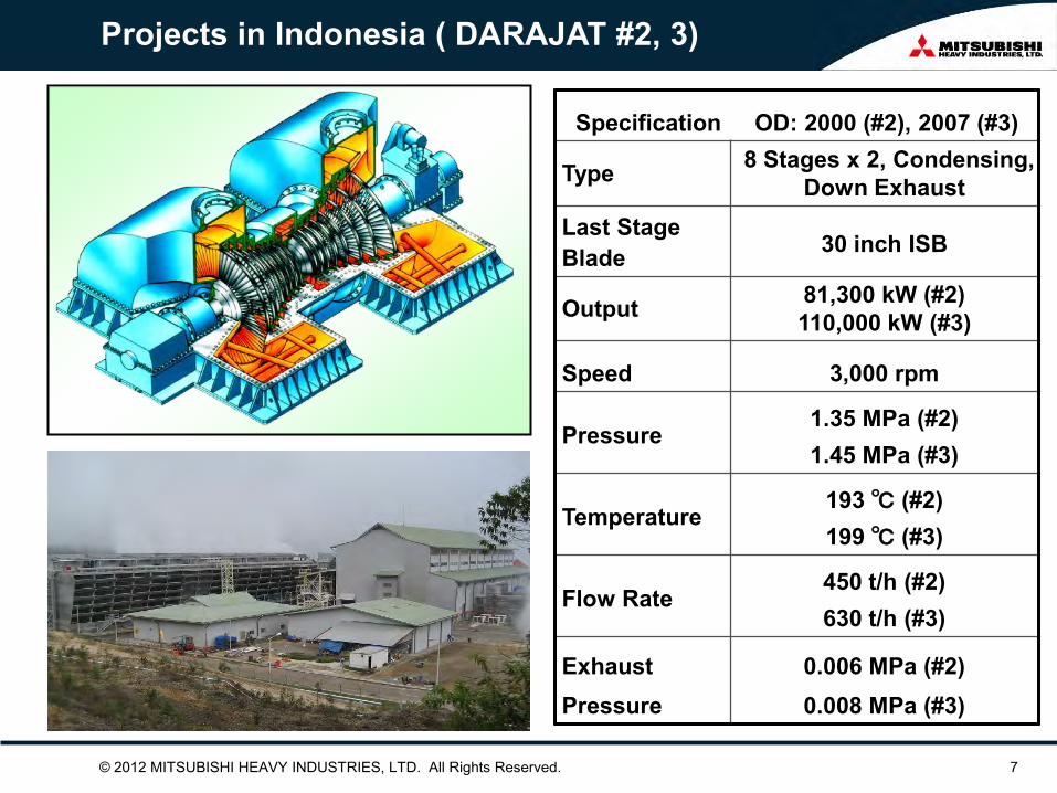
Projects in Indonesia ( DARAJAT #2, 3)
Specification OD: 2000 (#2), 2007 (#3)
Type 8 Stages x 2, Condensing, Down Exhaust
Last Stage Blade 30 inch ISB
Output 81,300 kW (#2) 110,000 kW (#3)
Speed 3,000 rpm
Pressure 1.35 MPa (#2) 1.45 MPa (#3)
Temperature 193 ℃ (#2) 199 ℃ (#3)
Flow Rate 450 t/h (#2) 630 t/h (#3)
Exhaust Pressure
0.006 MPa (#2) 0.008 MPa (#3)
© 2012 MITSUBISHI HEAVY INDUSTRIES, LTD. All Rights Reserved. 8
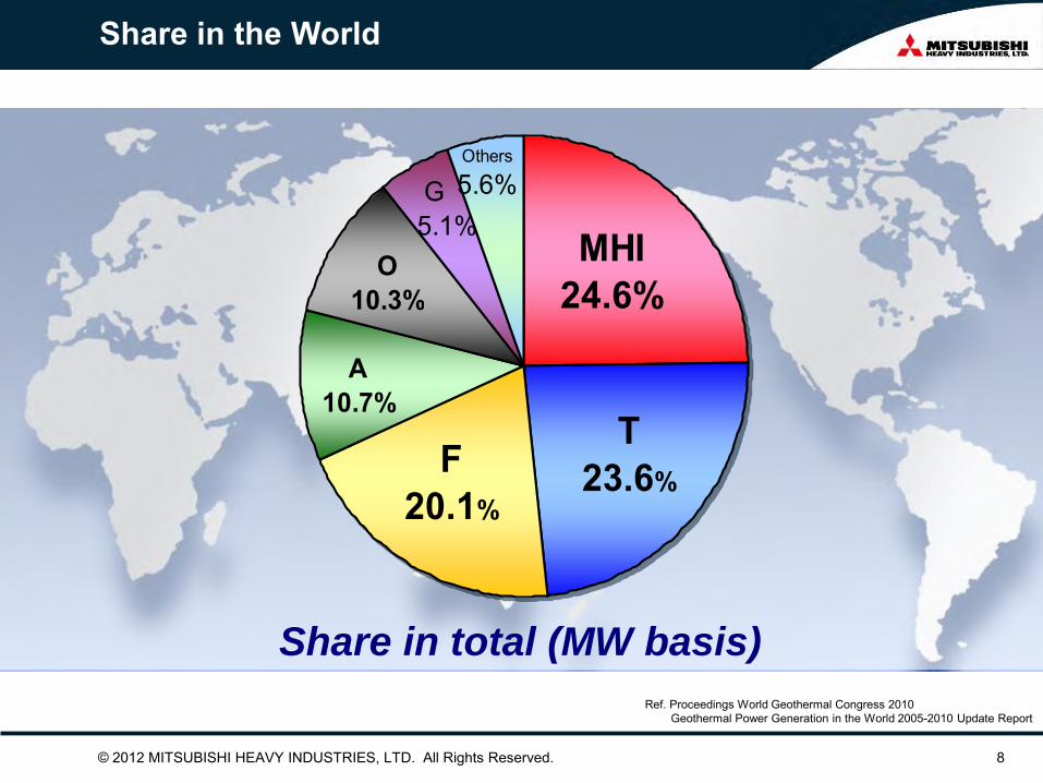
Share in the World
Share in total (MW basis)
MHI24.6%
T23.6%
F20.1%
A10.7%
O10.3%
5.1%
Others
5.6%G
Ref. Proceedings World Geothermal Congress 2010 Geothermal Power Generation in the World 2005-2010 Update Report

© 2012 MITSUBISHI HEAVY INDUSTRIES, LTD. All Rights Reserved. 9
Wide Output Range from 100kW to 151MW
UNITS
APPR
ICAT
ION
RAN
GE
(MW
)
SC1F
SC2F
TC4F
59
81414
181212
41111
0 5 10 15 20
~1
~10
~30
~50
~70
~90
~160
Approx. 60MW
Approx. 120MW

© 2012 MITSUBISHI HEAVY INDUSTRIES, LTD. All Rights Reserved. 10
Number of Casing (Exhaust Flow)
2
31
67
0 20 40 60 80
UNITS
TC4F
SC2F
SC1F
ST TYPE
© 2012 MITSUBISHI HEAVY INDUSTRIES, LTD. All Rights Reserved. 11
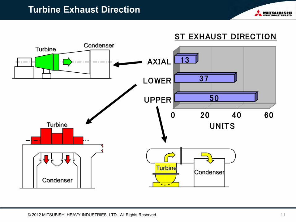
Turbine Exhaust Direction
Condenser
Turbine
Condenser
Condenser Turbine
50
37
13
0 20 40 60
UNITS
UPPER
LOWER
AXIAL
ST EXHAUST DIRECTION
Turbine
© 2012 MITSUBISHI HEAVY INDUSTRIES, LTD. All Rights Reserved. 12
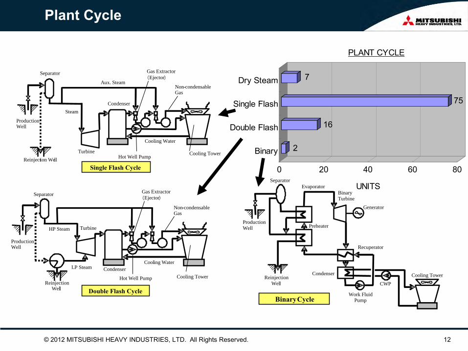
Plant Cycle
Aux. Steam
Turbine
Cooling Water
Cooling Tower
Non - condensable Gas
Hot Well Pump
Gas Extractor ( Ejector )
Steam
Separator
Production Well
Reinject ion We ll
Condenser
Single Flash Cycle
Turbine
Cool ing Water
Cooling Tower
Non - condensable Gas
Hot Well Pump
Gas Extractor ( Ejector )
HP Steam
Separator
Production Well
Condenser
Reinjection Wel l
LP Steam
Double Flash Cycle
Separator Evaporator
Production Well
Binary Turbine
Generator
R ecuperator
Cooling Tower CWP
Work Fluid Pump
Reinjection Wel l
Preheater
Condenser
Binary Cycle
2
16
75
7
0 20 40 60 80
UNITS
Binary
Double Flash
Single Flash
Dry Steam
PLANT CYCLE

© 2012 MITSUBISHI HEAVY INDUSTRIES, LTD. All Rights Reserved. 13
RECENT PROJECTS

© 2012 MITSUBISHI HEAVY INDUSTRIES, LTD. All Rights Reserved. 14
ICELAND HELLISHEIDI #1~#6

© 2012 MITSUBISHI HEAVY INDUSTRIES, LTD. All Rights Reserved. 15
ICELAND HELLISHEIDI #1~#6
FL 3300
FL 1925
FL 0
TURBINE GENERATOR
Specification #1 ~ 4(COD2006,2008) #5, 6(COD 2010)
Type 6 stage x 1, Condensing, Axial Exhaust
←
Last Stage Blade 30 inch ISB ← Output 40,000 kW ×4 units 45,000 kW ×2 units Speed 3,000 rpm ← Pressure 0.75 MPa ← Temperature 168 ˚C ← Exhaust Pressure 0.01 MPa ←
CONDENSER

© 2012 MITSUBISHI HEAVY INDUSTRIES, LTD. All Rights Reserved. 16
ICELAND HELLISHEIDI #1~#6
TURBINE SECTIONAL DRAWING

© 2012 MITSUBISHI HEAVY INDUSTRIES, LTD. All Rights Reserved. 17
ICELAND HELLISHEIDI #1~#6
Low Turbine House (Crane Level)
CRANE

© 2012 MITSUBISHI HEAVY INDUSTRIES, LTD. All Rights Reserved. 18
ICELAND HELLISHEIDI #1~#6
Complete Turbine Module fully assembled before Shipping

© 2012 MITSUBISHI HEAVY INDUSTRIES, LTD. All Rights Reserved. 19
ICELAND HELLISHEIDI #1~#6
Complete Turbine Module fully assembled before Shipping

© 2012 MITSUBISHI HEAVY INDUSTRIES, LTD. All Rights Reserved. 20
KENYA OLKARIA Ⅱ #1~#3
Specification OD: #1,2 2003, #3 2010
Type 6Stages x 1, Condensing,
Down Exhaust
Last Stage Blade 30 inch
Output 34,830 kW
Speed 3,000 rpm
Pressure 0.5 MPa
Temperature 150 ℃
Flow Rate 389 t/h
Exhaust Pressure 0.007 MPa

© 2012 MITSUBISHI HEAVY INDUSTRIES, LTD. All Rights Reserved. 21
TURKEY GERMENCIK
Specification OD: 2009
Type 6 Stages x 2, Condensing, Top Exhaust
Last Stage Blade 24 inch ISB
Output 47,400 kW
Speed 3,000 rpm
Pressure 0.588 MPa
Temperature 158 ℃
Exhaust Pressure
0.02 MPa
Feature
◆High Gas Content: 12.4% in HP steam ◆High Availability: 99.9% in first year

© 2012 MITSUBISHI HEAVY INDUSTRIES, LTD. All Rights Reserved. 22
ICELAND NESJAVELLIR #1~ #4
Specification OD: 1998 (Unit#1,2), 2001 (Unit#3), 2005 (Unit#4)
Type 8 Stages x 1, Condensing, Top Exhaust
Last Stage Blade
24 inch
Output 30,000 kW (Rated),
Speed 3,000 rpm
Pressure 1.2 MPa
Temperature 188 ℃
Flow Rate 206.1 t/h
Exhaust Pressure
0.02MPa

© 2012 MITSUBISHI HEAVY INDUSTRIES, LTD. All Rights Reserved. 23
JAPAN SUMIKAWA
Feature
◆Applied Top Exhaust Design to Double Flow
Turbine
◆Water Cooled Nozzle
Specification OD: 1995
Type 5Stages x 2,
Condensing, Top Exhaust
Last Stage Blade 23 inch Output 50,000 kW Speed 3,000 rpm Pressure 0.49 MPa Temperature 151 ℃ Flow Rate 389 t/h Exhaust Pressure 0.011 MPa
© 2012 MITSUBISHI HEAVY INDUSTRIES, LTD. All Rights Reserved. 24
2. What we can do for you

© 2012 MITSUBISHI HEAVY INDUSTRIES, LTD. All Rights Reserved. 25
Unit Output
・If you provide - Production Well Characteristic
- Atmospheric Conditions (Pressure and Wet Bulb Temperature)
・MHI propose ECONOMICAL Plant with - Optimum Cycle
- Optimum Design Conditions Main Steam Pressure Condenser Pressure Wet Bulb Temperature - Plant Output based on above conditions - Optimum Turbine Type with minimum exhaust loss

© 2012 MITSUBISHI HEAVY INDUSTRIES, LTD. All Rights Reserved. 26
Single Flash Cycle
Aux. Steam
Turbine
Cooling Water
Cooling Tower
Non-condensable Gas
Hot Well Pump
Gas Ejector
Steam
Separator
Production Well
Reinjection Well
Condenser
Vacuum Pump
© 2012 MITSUBISHI HEAVY INDUSTRIES, LTD. All Rights Reserved. 27
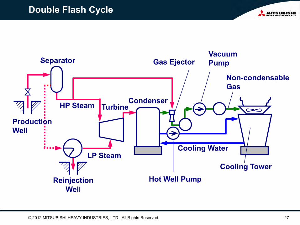
Double Flash Cycle
Turbine
Cooling Water
Cooling Tower Hot Well Pump
HP Steam
Separator
Production Well
Condenser
Reinjection Well
LP Steam
Non-condensable Gas
Vacuum Pump Gas Ejector

© 2012 MITSUBISHI HEAVY INDUSTRIES, LTD. All Rights Reserved. 28
10.0
15.0
20.0
25.0
30.0
150 200 250 300
Advantage Double Flash
Bottom Hole Temp. (℃)
ΔkW
(%)
*Calculated Conditions Brine flow rate of production well : Constant Turbine exhaust pressure : 0.1 bara HP main steam pressure : Optimized Pressure LP main steam pressure : Constant (1.2 bara)

© 2012 MITSUBISHI HEAVY INDUSTRIES, LTD. All Rights Reserved. 29
Main Steam Pressure
0
100
200
300
400
500
600
0 5 10 15Main Steam Pressure (bara.)
Stea
m F
low
(ton
/h)
40
50
60
70
80
0 5 10 15Main Steam Pressure (bara.)
Gen
erat
or O
utpu
t (M
W)
Conditions : ・Turbine Exhaust Press. = 0.1 bara ・Inlet Steam : Saturated
Steam Flow
Heat Drop in
Turbine
MW ∝ X

© 2012 MITSUBISHI HEAVY INDUSTRIES, LTD. All Rights Reserved. 30
Main Steam Pressure
5
10
15
20
0 5 10 15Main Steam Pressure (bara.)
Wet
ness
of T
urbi
ne E
xhau
st (%
) Exhaust Press. = 0.05 bara
0.10 bara
0.15 bara
© 2012 MITSUBISHI HEAVY INDUSTRIES, LTD. All Rights Reserved. 31
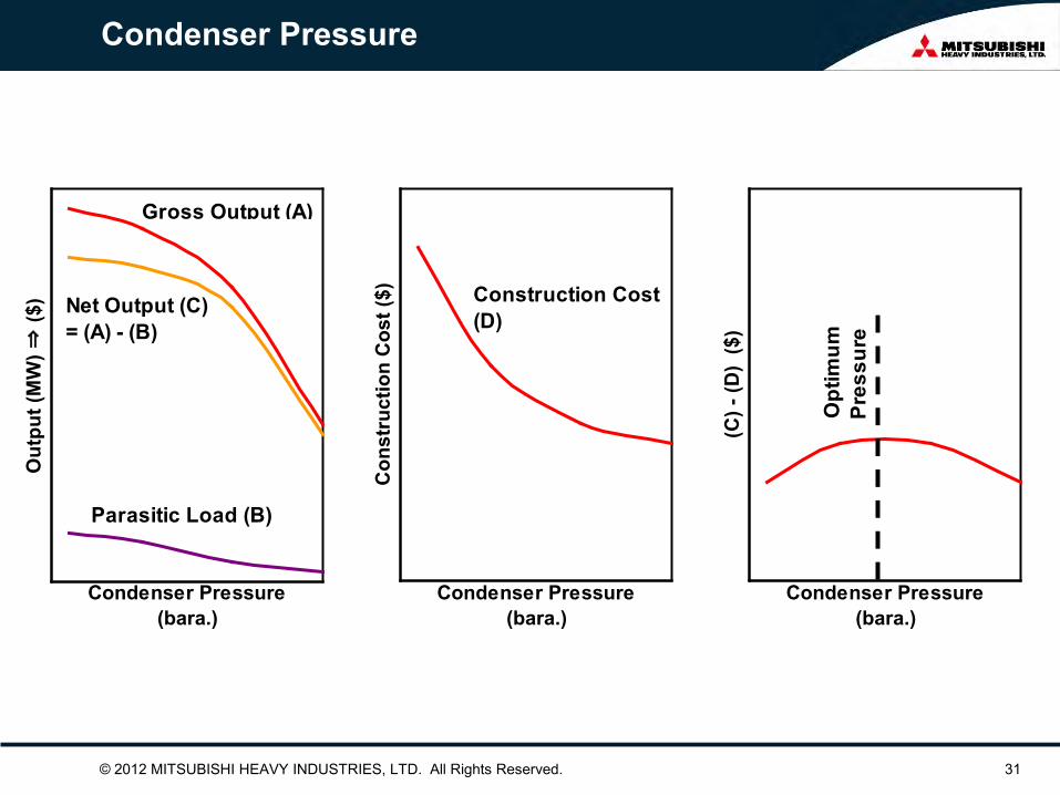
Condenser Pressure
Condenser Pressure(bara.)
Out
put (
MW
) ⇒ ($
)
Gross Output (A)
Net Output (C)= (A) - (B)
Parasitic Load (B)
Condenser Pressure(bara.)
Con
stru
ctio
n C
ost (
$) Construction Cost(D)
Condenser Pressure(bara.)
(C) -
(D)
($)
Opt
imum
Pres
sure

© 2012 MITSUBISHI HEAVY INDUSTRIES, LTD. All Rights Reserved. 32
Design Wet Bulb Temperature
Case-1 Case-2
Design Wet Bulb Temp. Low High
Generator Output Low High
Cost for Cooling Water System
Low High
Design Wet Bulb Temp.
Case-1
Case-2
Case-1
Case-2
90
100
110
Gen
erat
or O
utpu
t (%
)
(month)
0
10
20
30
0 2 4 6 8 10 12
Wet
Bul
b Te
mp.
(℃)

© 2012 MITSUBISHI HEAVY INDUSTRIES, LTD. All Rights Reserved. 33
3. Technologies for higher performance and reliabilities

40
Last Stage Stationary: Drain Groove/Hallow Blade
Last Stage Rotating Blade:Stelight Shield
Rotor Material:Low Sulfiur CrMoV Alloy Rotating Blade
Material:12Cr, 17-4PH
Nozzle Material:12Cr,18Cr-8Ni
High Stress Part in Rotor: Shot Peening
Rotor Disc: Low stress by Tapered Shape
Standard Feature for Geothermal Steam Turbine
Rotating Blade: Integral Shroud Blade
Drain Chatcher

41
Casing(Carbon Steel): Diaphragm Fitting Part : Stainless Welding
Rotor Material:12Cr Alloy
Rotor Gland:Inconel Coating (for Low Sulfur CrMoV Alloy)
Rotating Blade:Titanium Alloy
Diaphragm(Carbon Steel)Horizontal Surface and Fitting Part : Stainless Welding
Optional Feature for Dirty Steam

© 2012 MITSUBISHI HEAVY INDUSTRIES, LTD. All Rights Reserved. 42
Con
vent
iona
l 3-D Design Blade
3-D
Des
ign
Efficiency Improvement due to 3-D Nozzle
Conventional
F3-D Nozzle
Velocity Ratio 0.2 0.3 0.4 0.5 0.6 0.7 0.8
1.15
1.10
1.05
1.00
0.95
0.90
0.85 Inte
rnal
Effi
cien
cy R
atio

© 2012 MITSUBISHI HEAVY INDUSTRIES, LTD. All Rights Reserved. 43
Erosion Protection
Stellite Strip
Stellite Strip on Moving Blade
Hollow Nozzle
Drain Hole
Drain Hole
To Turbine Exhaust
Drain Ditch on Stationary Blade
Ditch
Ditch Drain

© 2012 MITSUBISHI HEAVY INDUSTRIES, LTD. All Rights Reserved. 44
Measures Against Scaling (at 1st Stage Nozzle)
: Clogged Condition
How to Supervise
Scaling
G: Flow Rate P: Pressure at Nozzle Inlet
A: Nozzle Flow Area
A
: Clean Condition
: Clogged
G ∝ P x A ∝
(P/G)0
1 A
Measures
Verification in Actual Turbine
Conventional Nozzle
Water Cooled Nozzle
After 9 Months Operation
Water Cooled Nozzle
To Water Cooler
Steam
Cooling Water
Cooling Water Hole
Nozzle
Width Convex
Concave
Steam (Inlet)
Steam (Outlet)
Flow Area
Steam Temp.
Nozzle Metal Temp.
Conventional Nozzle
Water Cooled Nozzle
Re- Evaporation
No Re-Evaporation
Temperature Distribution
0
1 目 2 目 3 目
1%の水噴射 2%の水噴射
Scrubber & Blade Washing
Scrubber
Geothermal Steam Clean Steam To Turbine
Separator
Injection Pump
Clean Water ( 10 % of Steam) ~ ~
Drain with Impurity
Clean Water ( 2 % of Steam) ~ ~
To Turbine
Geothermal Steam
Blade Washing
0 24 48 72 (Hour)
10
5
1 % Water Inject 2 % Water Inject
Test Results in Actual Turbine
(P/G
) 0
(P/G
) 0
(P/G
) -
Narrower Flow Area
Less Output

© 2012 MITSUBISHI HEAVY INDUSTRIES, LTD. All Rights Reserved. 45
PEEK LINING BEARING
0
20
40
60
80
100
120
従来軸受(ホワイトメタル) 次世代PEEK樹脂軸受
軸受損失比 %
62%減
PEEK : PolyEtherEtherKetone
Journal Bearing
Thrust Bearing
Higher allowable contact pressure - Downsizing - Lower mechanical loss
PEEK Conventional (White metal)
62% Reduction
0
20
40
60
80
100
Bea
ring
Loss
[%]
© 2012 MITSUBISHI HEAVY INDUSTRIES, LTD. All Rights Reserved. 46
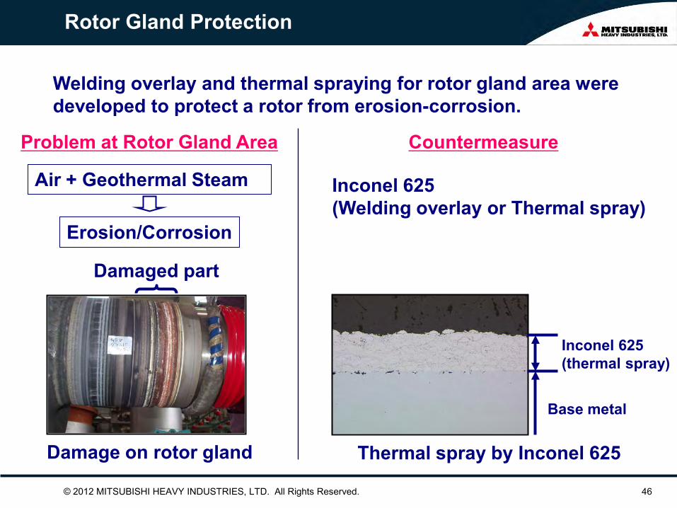
Rotor Gland Protection
Welding overlay and thermal spraying for rotor gland area were developed to protect a rotor from erosion-corrosion.
Inconel 625 (thermal spray)
Base metal
Thermal spray by Inconel 625
Damaged part
Damage on rotor gland
Air + Geothermal Steam
Erosion/Corrosion
Problem at Rotor Gland Area Countermeasure
Inconel 625 (Welding overlay or Thermal spray)

© 2012 MITSUBISHI HEAVY INDUSTRIES, LTD. All Rights Reserved. 47
Material Selection for Geothermal Turbine
*: Tested in Actual Geothermal Steam
_
Susceptibility against SCC*
0.0015 0.023 mm/Year Corrosion Rate* < 40 < 80 ℃ 50 % FATT
> 30 > 20 J Absorbed Impact Energy at 25 ℃
> 45 > 40 % Deduction in Area
> 16 > 15 % Elongation
> 740 > 740 MPa Tensile Strength
> 635 > 635 MPa 0.2 % Yield Stress
10325GSR1 10325MGB Unit Property
at σ0.2 x 3.3 at σ0.2 x 3.3
Moving Blade 1. Materials
12Cr (10705BA) ◆ For Intermediate Stages 17-4PH (10705BX, 10725BX, 10725DW) ◆ For 1st Stage and Last 2 ~ 3 Stages ◆ Tensile Strength, Corrosion Fatigue Strength: Higher ◆ Corrosion Rate: Lower Titanium Alloy (Ti-6A-4V) ◆ For 1st Stage in Very Corrosive Geothermal Steam ◆ Tensile Strength, Corrosion Fatigue Strength: Highest ◆ Corrosion Rate: Lowest
Ti-6A-4V
17-4PH
12Cr
Corrosion Fatigue Strength (in Geothermal Steam)
50 40 30 20
105 106 107 108
Failu
re S
tres
s (k
g/m
m2 )
Ti-6A-4V SUS 304
SUS 316
17-4PH
SS400
SB410
12CrMo
8
6 4 2
Corrosion Rate in Geothermal Steam
Material
Cor
rosi
on R
ate
(mg/
cm2 /3
Mon
ths)
Rotor 1. Materials
Low Sulfur CrMoV (10325MGB) ◆ Standard Material ◆ Low Susceptibility against SCC 12Cr (10325GSR) ◆ For Very Corrosive Geothermal Steam ◆ Low Susceptibility against SCC ◆ Low Corrosive Rate ◆ High Toughness 2. Mechanical Properties
© 2012 MITSUBISHI HEAVY INDUSTRIES, LTD. All Rights Reserved. 48
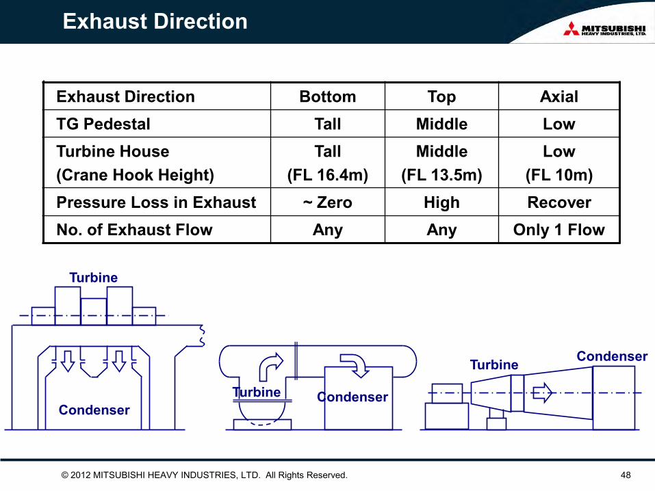
Exhaust Direction
Exhaust Direction Bottom Top Axial TG Pedestal Tall Middle Low Turbine House (Crane Hook Height)
Tall (FL 16.4m)
Middle (FL 13.5m)
Low (FL 10m)
Pressure Loss in Exhaust ~ Zero High Recover No. of Exhaust Flow Any Any Only 1 Flow
Condenser
Turbine
Condenser Turbine
Condenser Turbine
© 2012 MITSUBISHI HEAVY INDUSTRIES, LTD. All Rights Reserved. 49
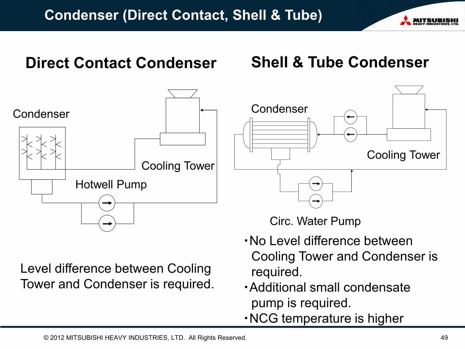
Condenser (Direct Contact, Shell & Tube)
Direct Contact Condenser Shell & Tube Condenser
Cooling Tower
Condenser
Hotwell Pump
Cooling Tower
Condenser
Circ. Water Pump
・No Level difference between Cooling Tower and Condenser is required. ・Additional small condensate pump is required. ・NCG temperature is higher
Level difference between Cooling Tower and Condenser is required.

© 2012 MITSUBISHI HEAVY INDUSTRIES, LTD. All Rights Reserved. 50
Condenser (Direct Contact vs. Shell & Tube)
Direct Contact Shell & Tube
Condenser at lower level than turbine.
Condenser at the same level as turbine.

© 2012 MITSUBISHI HEAVY INDUSTRIES, LTD. All Rights Reserved. 51
ICELAND HELLISHEIDI #1~#6
Shell & Tube Condenser

© 2012 MITSUBISHI HEAVY INDUSTRIES, LTD. All Rights Reserved. 52
Advanced Direct Contact Condenser (ADCC)

© 2012 MITSUBISHI HEAVY INDUSTRIES, LTD. All Rights Reserved. 53
Advanced Direct Contact Condenser (ADCC)
© 2012 MITSUBISHI HEAVY INDUSTRIES, LTD. All Rights Reserved. 54
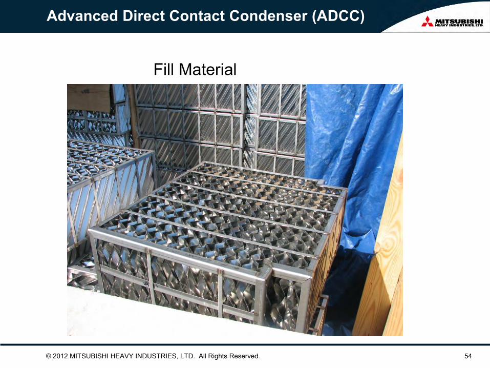
Advanced Direct Contact Condenser (ADCC)
Fill Material
© 2012 MITSUBISHI HEAVY INDUSTRIES, LTD. All Rights Reserved.
CONTROL SYSTEMS DEPARTMENT

© 2012 MITSUBISHI HEAVY INDUSTRIES, LTD. All Rights Reserved. 56
Installation Records of DIASYS ( for Power Plant )
© 2012 MITSUBISHI HEAVY INDUSTRIES, LTD. All Rights Reserved. 57
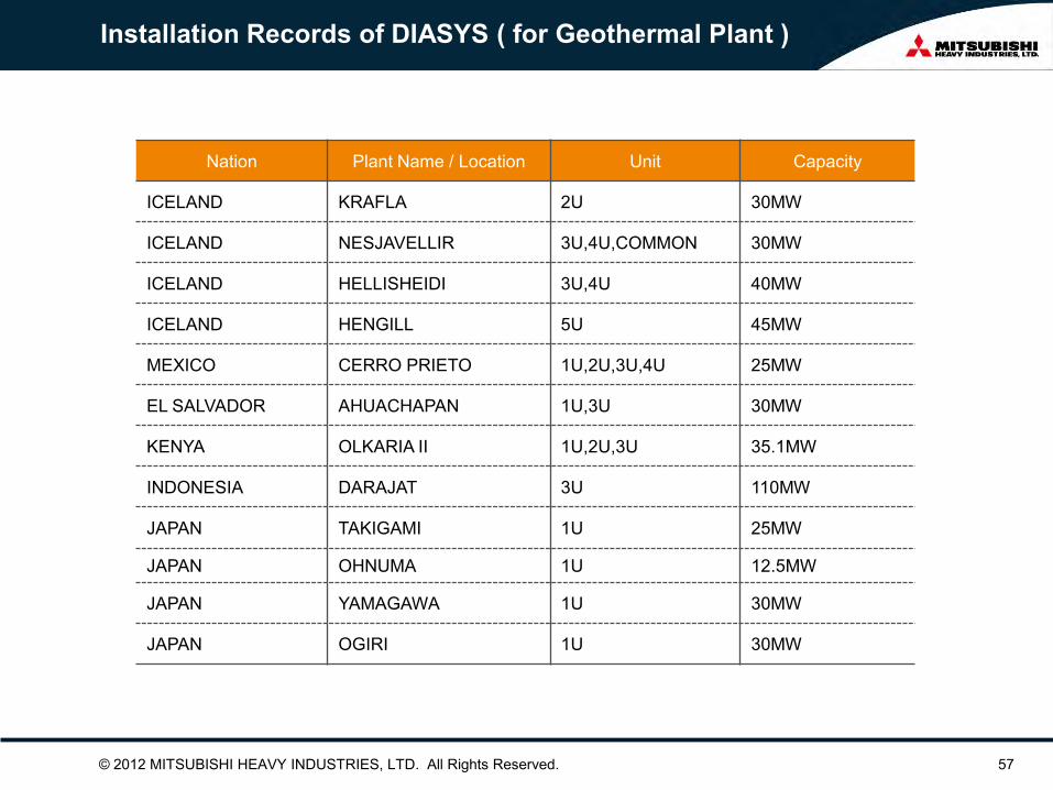
Installation Records of DIASYS ( for Geothermal Plant )
Nation Plant Name / Location Unit Capacity
ICELAND KRAFLA 2U 30MW
ICELAND NESJAVELLIR 3U,4U,COMMON 30MW
ICELAND HELLISHEIDI 3U,4U 40MW
ICELAND HENGILL 5U 45MW
MEXICO CERRO PRIETO 1U,2U,3U,4U 25MW
EL SALVADOR AHUACHAPAN 1U,3U 30MW
KENYA OLKARIA II 1U,2U,3U 35.1MW
INDONESIA DARAJAT 3U 110MW
JAPAN TAKIGAMI 1U 25MW
JAPAN OHNUMA 1U 12.5MW
JAPAN YAMAGAWA 1U 30MW
JAPAN OGIRI 1U 30MW

© 2012 MITSUBISHI HEAVY INDUSTRIES, LTD. All Rights Reserved. 58
High Speed , Critical and Scalability
For Total DCS Use -Combined Cycle / Conventional Power / Coal Gasification -Plant Coordination Control / Automatic Start & Shutdown Control, Training Simulator
For Critical Control Use -Steam/Gas Turbine Speed Control & Interlock System -Gas Engine / Turbine for Shipment -Super Critical Boiler
For Utility Control Use -Desulfurizing Plant -Coal Handling -Water Treatment
Applied to Wide Range of Power Plant