getting started ii - wirefusion 5 - demicron · this tutorial requires that you are familiar with...
TRANSCRIPT

Getting StartedVolume II: 3D in WireFusion 5
Tutorial


Contents INTRODUCTION..........................................................................................................................1 REQUIREMENTS ........................................................................................................................1
User Requirements .............................................................................................................1 System Requirements.........................................................................................................1
RESOURCE FILES......................................................................................................................1 GENERAL WORKFLOW...............................................................................................................2 PHOTOS ...................................................................................................................................5
PART I........................................................................................................................................6 3D MODELING IN 3DS MAX ........................................................................................................6
Image Reference ................................................................................................................6 Polygon Modeling ...............................................................................................................8 Materials............................................................................................................................18 Animations ........................................................................................................................21 Export................................................................................................................................22
PART II.....................................................................................................................................25 WIREFUSION ..........................................................................................................................25
Import the 3D model .........................................................................................................25 Tuning of the 3D model.....................................................................................................26 Interface ............................................................................................................................34 Navigation .........................................................................................................................36 Reset Camera...................................................................................................................40 Touch Sensors..................................................................................................................41 Animations I – Simple Logic..............................................................................................43 Animations II – Advanced Logic .......................................................................................44 Adding Hotspot Labels......................................................................................................48 Optimize Project................................................................................................................57 Publish ..............................................................................................................................62
PART III....................................................................................................................................64 HTML EDITING IN DREAMWEAVER ...........................................................................................64 SUMMARY...............................................................................................................................66


Introduction
1
Introduction Welcome to Getting Started, Volume II. This tutorial will guide you through the entire proc-ess of creating a WireFusion Web3D presentation - from 3D modeling to a final presentation running on the web. We will create an interactive product presentation of a tape rule, which will contain e.g. object animations, touch sensors, user interface and real-time shadows. The 3D modeling part in this tutorial is quite brief, as it is expected that you are already famil-iar with 3D modeling.
Requirements
User Requirements This tutorial requires that you are familiar with 3D modeling, using either Autodesk 3ds Max®, or any other 3D authoring tool capable of exporting to X3D or VRML (VRML2/VRML97). It is also highly recommended that you work through the WireFusion tutorial Getting Started, Volume I, in which you will learn the basics of WireFusion.
System Requirements You will need the following tools in order to complete this tutorial:
• A 3D authoring tool capable of exporting to X3D or VRML (VRML2/VRML97). In this tuto-rial we use Autodesk 3ds Max 7.
• A graphics software that can save pictures in JPEG, transparent GIF and transparent PNG. In this tutorial we use Adobe Photoshop®.
• Any edition of WireFusion 5.0.4 (or later).
• An HTML editor and FTP client. In this tutorial we use Adobe Dreamweaver®.
Resource Files The resource files for this tutorial can be found in:
[Path]/My Documents/WireFusion/resources/tutorials/tape_rule/

Getting Started – Volume II: 3D Tutorial
General Workflow The general workflow for this tutorial is: 1. Take photos of the tape rule (Figure 1).
Figure 1: Taking photos of the tape rule
2. Model, texture and animate the tape rule in Autodesk 3ds Max. Export from 3ds Max to VRML (Figure 2).
Figure 2: Modeling of the tape rule
2
General Workflow
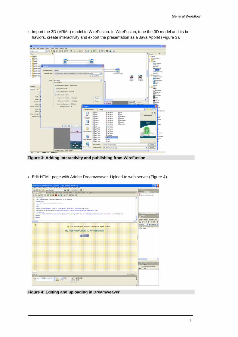
3. Import the 3D (VRML) model to WireFusion. In WireFusion, tune the 3D model and its be-haviors, create interactivity and export the presentation as a Java Applet (Figure 3).
Figure 3: Adding interactivity and publishing from WireFusion
4. Edit HTML page with Adobe Dreamweaver. Upload to web server (Figure 4).
Figure 4: Editing and uploading in Dreamweaver
3

Getting Started – Volume II: 3D Tutorial
5. Test online in a web browser (Figure 5).
Figure 5: Testing in the browser
4

Photos
5
Photos To create a nice realistic 3D model from a real physical object, we generally start by taking pictures of the object (Figure 1). We then use these pictures for the following purposes:
• As reference images in the 3D authoring tool while modeling. We take photos from the Front, Top, Back, Bottom, Left and Right views. Possibly also from different object con-figurations.
• As textures that we apply on the 3D model.
NOTE: The picture quality should be as good as possible, which means no barrel distortion and as little re-flections as possible. In order to capture small objects and details, and to get sharp pictures, we recommend using a macro lens. All the photos should be taken in the same light conditions. Image quality is a key factor for a good result.

Getting Started – Volume II: 3D Tutorial
Part I
3D Modeling in 3ds Max
NOTE: If you want to skip the 3D modeling part you can go directly to the WireFusion section and load a ready-made model. If you want to examine the final MAX file in 3ds Max, then load the following:
[Path]/My Documents/WireFusion/resources/tutorials//tape_rule/tape_rule.max
Image Reference In order to build the 3D model as exact as possible, we will use reference images of the tape rule as background images. However, rather than using the built-in Viewport Background function, found in 3ds Max, we will use another method instead:
1. From the Create panel, create a Box primitive.
2. Press M to open the Material Editor, and then load 'help-1-1.jpg' as diffuse material (Figure 6).
[Path]/My Documents/WireFusion/resources/tutorials/tape_rule/help-1-1.jpg
Figure 6: Loading a reference image
3. To display materials on the surfaces in the viewports, choose Material Editor > Material >
Select Map in Viewport
6
3D Modeling in 3ds Max
4. With the box selected, click the Assign Material to Selection button.
5. In the Modify panel, edit the size of the box. Set Width to 512 and Length to 415.
NOTE: In order to have no distortion, the box should have the same size (proportions) as the picture, i.e. 512x415.
6. Convert the box to polygon by right clicking the box, then choose Convert to: Convert to Editable Poly
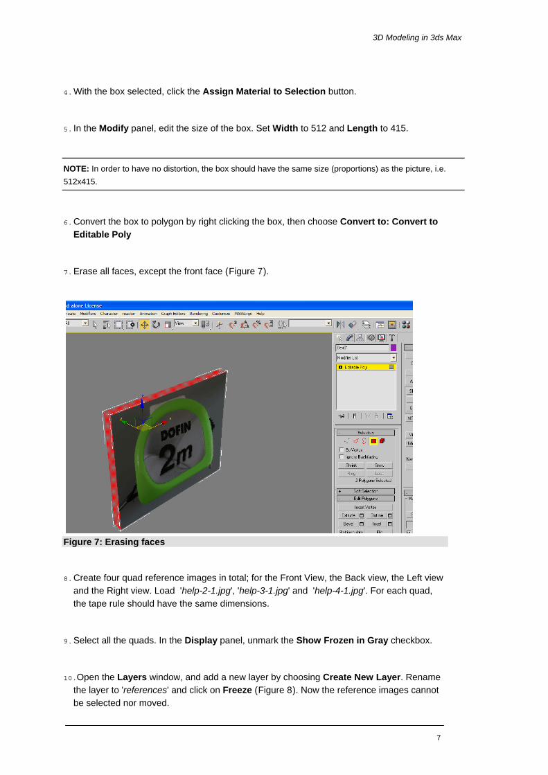
7. Erase all faces, except the front face (Figure 7).
Figure 7: Erasing faces
8. Create four quad reference images in total; for the Front View, the Back view, the Left view
and the Right view. Load 'help-2-1.jpg', 'help-3-1.jpg' and 'help-4-1.jpg'. For each quad, the tape rule should have the same dimensions.
9. Select all the quads. In the Display panel, unmark the Show Frozen in Gray checkbox.
10.Open the Layers window, and add a new layer by choosing Create New Layer. Rename the layer to 'references' and click on Freeze (Figure 8). Now the reference images cannot be selected nor moved.
7

Getting Started – Volume II: 3D Tutorial
Figure 8: Freezing the quads in a layer
Polygon Modeling 1. Select the Front View viewport and click on the Min/Max Toggle button (or press
ALT+W).
2. Most objects can be built from a box primitive. However, in this case we will start with a cylinder primitive. Create a Cylinder with only one height segment and 18 sides.
3. Press ALT+X to make the cylinder translucent, and press F4 to display the edges (Figure 9).
8

3D Modeling in 3ds Max
Figure 9: A translucent cylinder with edges
4. Convert the cylinder to Poly. With the help of the reference image, build the front side of
the tape rule by moving the vertices (Figure 10).
Figure 10: Vertices moved to fit the reference image
9

Getting Started – Volume II: 3D Tutorial
5. Bevel the front side and the backside of the tape rule, and arrange the vertices positions (Figure 11).
Figure 11: Bevel the front side
6. Use the Slice Plane command to cut the faces (Figure 12).
Figure 12: Cutting faces with the Slide Plane
10
3D Modeling in 3ds Max
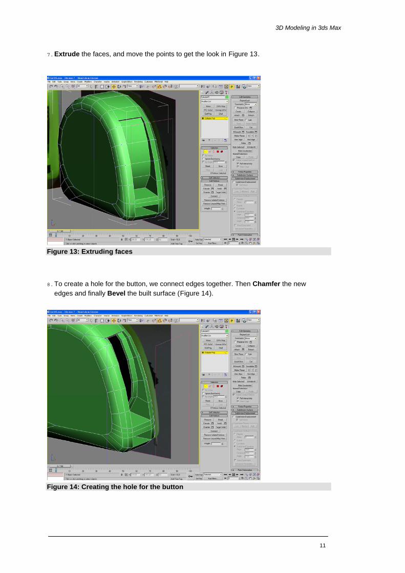
7. Extrude the faces, and move the points to get the look in Figure 13.
Figure 13: Extruding faces
8. To create a hole for the button, we connect edges together. Then Chamfer the new edges and finally Bevel the built surface (Figure 14).
Figure 14: Creating the hole for the button
11
Getting Started – Volume II: 3D Tutorial
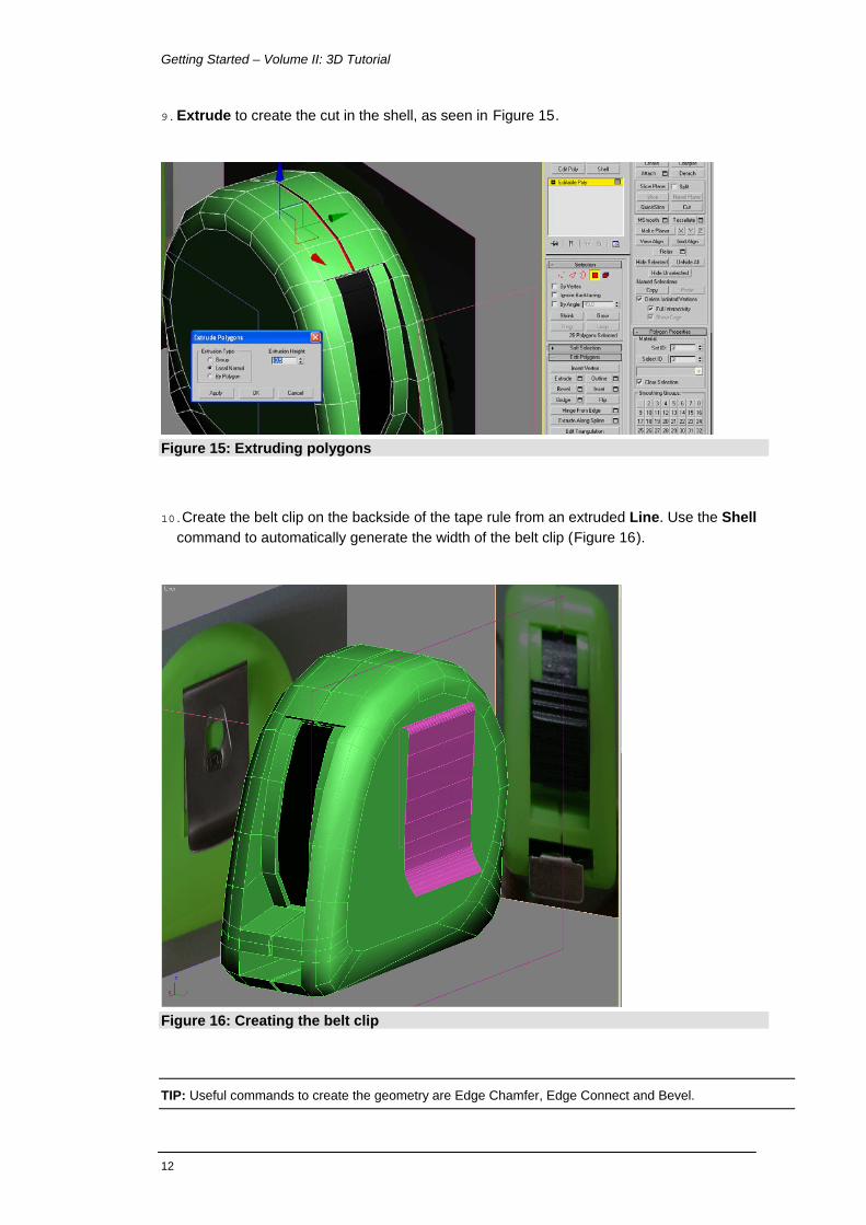
9. Extrude to create the cut in the shell, as seen in Figure 15.
Figure 15: Extruding polygons
10.Create the belt clip on the backside of the tape rule from an extruded Line. Use the Shell command to automatically generate the width of the belt clip (Figure 16).
Figure 16: Creating the belt clip
TIP: Useful commands to create the geometry are Edge Chamfer, Edge Connect and Bevel.
12
3D Modeling in 3ds Max
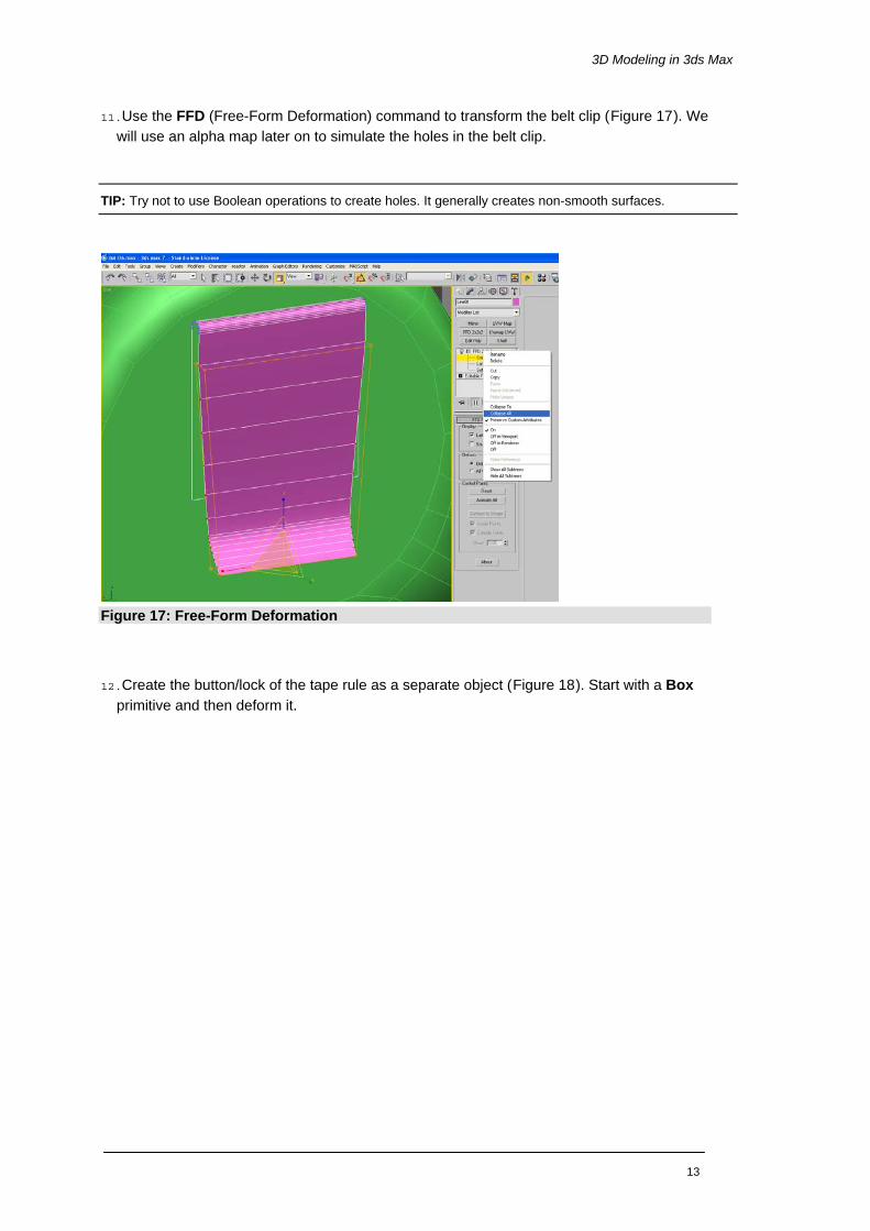
11.Use the FFD (Free-Form Deformation) command to transform the belt clip (Figure 17). We will use an alpha map later on to simulate the holes in the belt clip.
TIP: Try not to use Boolean operations to create holes. It generally creates non-smooth surfaces.
Figure 17: Free-Form Deformation
12.Create the button/lock of the tape rule as a separate object (Figure 18). Start with a Box primitive and then deform it.
13

Getting Started – Volume II: 3D Tutorial
Figure 18: Creating the button/lock
13.To create the cord, use Splines > Line (Figure 19) Then use Extrude and Shell to de-form it.
Figure 19: Creating the cord using a line spline
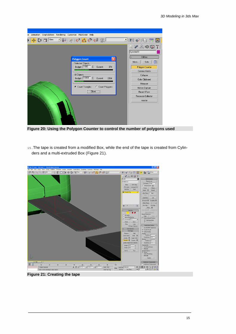
14.We are almost finished with the geometry process. Control the polygon counts, by choos-ing Utilities panel > Polygon Counter (Figure 20). The default polygon budget in 3ds Max is 10.000 polygons, which is a good guideline for Web3D presentations created with Wire-Fusion.
14
3D Modeling in 3ds Max
Figure 20: Using the Polygon Counter to control the number of polygons used
15.The tape is created from a modified Box, while the end of the tape is created from Cylin-ders and a multi-extruded Box (Figure 21).
Figure 21: Creating the tape
15

Getting Started – Volume II: 3D Tutorial
16.When assigning NURMS Subdivision, there are a lot of artifacts (Figure 22). To fix the artifacts, use the Separate by Smoothing Groups. In the Smoothing Groups panel, as-sign the same number to faces belonging to the same surface.
Figure 22: NURMS Subdivision with artifacts
After assigning the Smoothing Groups correctly you should get a result similar to Figure 23.
Figure 23: Smoothing groups assigned
16

3D Modeling in 3ds Max
The fact that we applied NURMS Subdivision has doubled the triangle count of the scene. We now have about 4 300 polygons in the scene. However, we are still in our initial budget, which is 10 000 polygons (Figure 24).
Figure 24: 4 300 polygons and smooth result
17

Getting Started – Volume II: 3D Tutorial
Materials Even though WireFusion is not limited to any specific texture size, you should always keep in mind that texture maps should be as small as possible. Large textures will slow down the presentation and increase initial startup time. WireFusion has no upper limit for the dimen-sions of the texture maps either, but we recommend using the power of 2, e.g. 512X128, 256x256 etc. This rule generally improves memory allocation, and speeds up the presenta-tion.
Figure 25: Creating a texture map of 512x128 in Adobe Photoshop
1. Use UVW Map or UnWrap UVW to arrange the position of the textures (Figure 26).
Figure 26: Using UVW Mapping
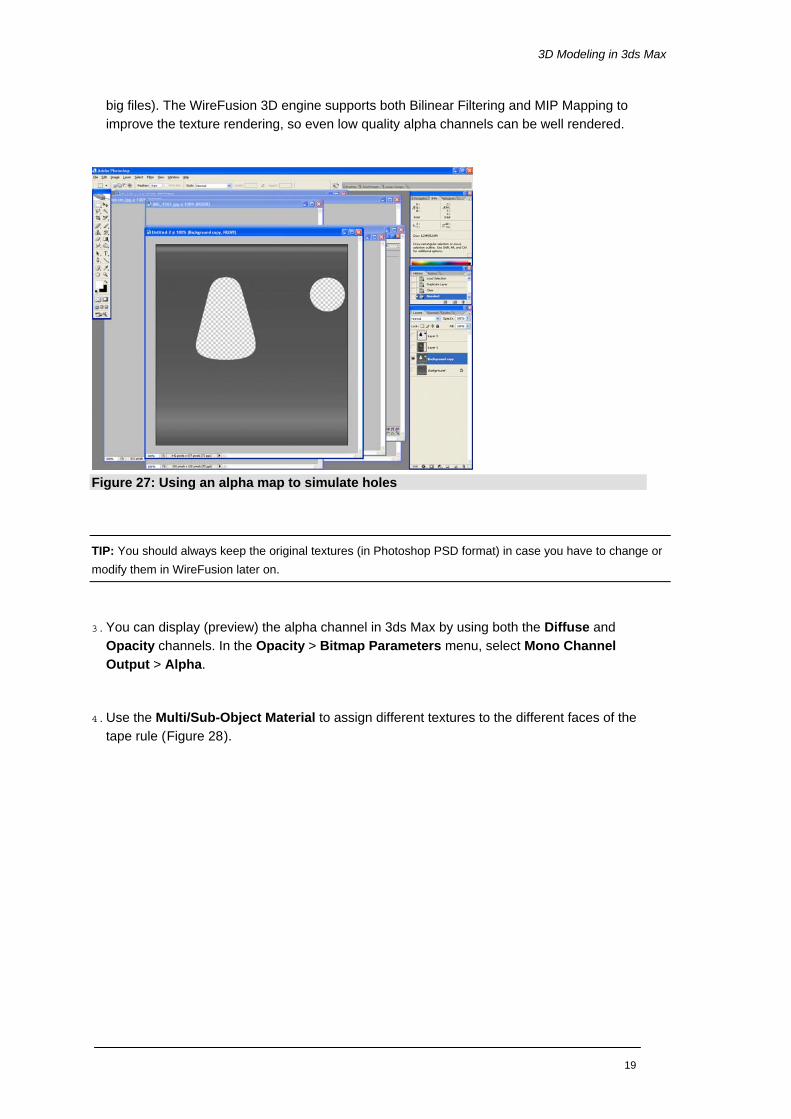
2. Instead of making a hole in the geometry of the belt clip, we will use a transparent texture map (Figure 27). Save the file as a transparent PNG-8 (8-bits) file (PNG-24 generates too
18
3D Modeling in 3ds Max
big files). The WireFusion 3D engine supports both Bilinear Filtering and MIP Mapping to improve the texture rendering, so even low quality alpha channels can be well rendered.
Figure 27: Using an alpha map to simulate holes
TIP: You should always keep the original textures (in Photoshop PSD format) in case you have to change or modify them in WireFusion later on.
3. You can display (preview) the alpha channel in 3ds Max by using both the Diffuse and Opacity channels. In the Opacity > Bitmap Parameters menu, select Mono Channel Output > Alpha.
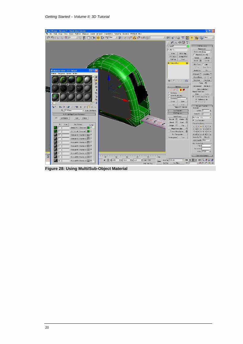
4. Use the Multi/Sub-Object Material to assign different textures to the different faces of the tape rule (Figure 28).
19
Getting Started – Volume II: 3D Tutorial
Figure 28: Using Multi/Sub-Object Material
20

3D Modeling in 3ds Max
Animations We will animate three elements in the scene using the Auto Key function; we will animate the button, the belt clip and the tape.
1. To create an animation, click the Auto Key button. Change the current frame on the Time Slider, then transform the object you want to animate (Figure 29).
Figure 29: Using Auto Key for animations
2. The button object is a simple translation, while the belt clip is a vertex animation.
3. For the tape animation we want both the tape object and the tape end object to be ani-mated. Instead of having two separate animations we link the objects together. We make the tape object a Parent to the tape end object, which becomes a Child. To link the ob-jects, use the Select and Link function (Figure 30). When you move the parent object, then the child object follows. If you move the child, then the parent is not affected.
21

Getting Started – Volume II: 3D Tutorial
Figure 30: Linking the tape and the tape end as child and parent
Export 1. Before exporting the final model, we center the objects according to the origin of the coor-
dinates, also known as Center of the Universe in 3ds Max (Figure 31).
Figure 31: Center the model
22
3D Modeling in 3ds Max
2. Rename the objects in your model to meaningful names. It will make it easier when working in WireFusion.
NOTE: We are not using light sources in this project. We will use reflection maps in WireFusion instead.
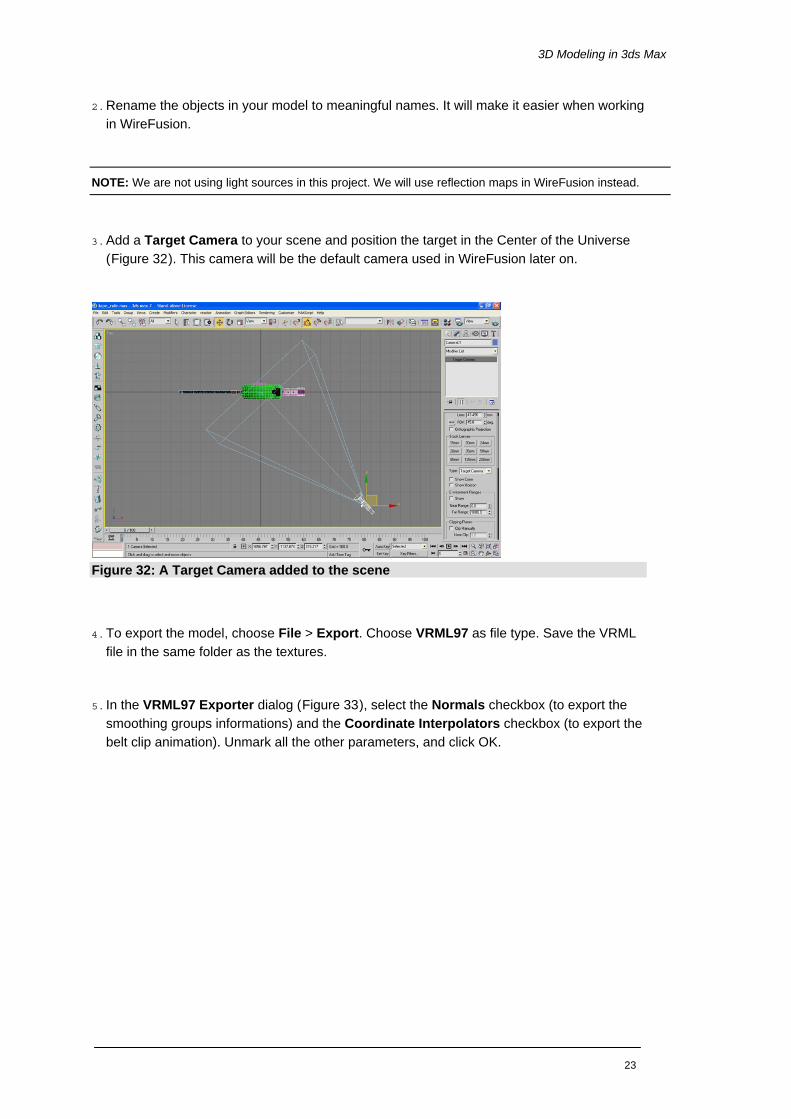
3. Add a Target Camera to your scene and position the target in the Center of the Universe (Figure 32). This camera will be the default camera used in WireFusion later on.
Figure 32: A Target Camera added to the scene
4. To export the model, choose File > Export. Choose VRML97 as file type. Save the VRML file in the same folder as the textures.
5. In the VRML97 Exporter dialog (Figure 33), select the Normals checkbox (to export the smoothing groups informations) and the Coordinate Interpolators checkbox (to export the belt clip animation). Unmark all the other parameters, and click OK.
23

Getting Started – Volume II: 3D Tutorial
Figure 33: VRML 97 Exporter dialog
Now the VRML file has been exported and it is time to start working in WireFusion.
24

WireFusion
Part II
WireFusion
Import the 3D model Now it is time to launch WireFusion. You can optionally keep 3ds Max open, as it is possible to re-import the 3D scene in case you would need to modify the original scene in 3ds Max. 1. From Objects > 3D, insert a 3D Scene object into the Script Area (Figure 34).
Figure 34: Inserting a 3D Scene object
2. When dropping the object you have to choose what type of 3D model you intend to import; either a 3D Object (Examine mode) or a 3D World (Walk mode). From the Load Option dialog, choose 3D Object and click OK (Figure 35).
25

Getting Started – Volume II: 3D Tutorial
Figure 35: Choosing the type of 3D model to load
3. Load the VRML file 'tape_rule.wrl':
[Path]/My Documents/WireFusion/resources/tutorials/tape_rule/tape_rule.wfp
Tuning of the 3D model When the 3D Scene dialog opens, you will find a Preview window in the middle of the dialog containing your 3D model (Figure 36).
NOTE: If you do not see anything in the Preview window, then you probably have not added a camera in 3ds Max before exporting. Make sure to add a camera before exporting, or let WireFusion add one for you when importing by selecting the Generate default camera checkbox.
26

WireFusion
Figure 36: 3D Scene dialog opened
4. In the toolbar, set the Target Area size for the 3D Scene object (and Preview window size). Set the Width to 400 and Height to 400 (Figure 37).
Figure 37: The 3D Scene toolbar
5. In the Navigation panel > Navigation Speed, set Zoom and Pan speed to 20, and the Friction slider to 30 (Figure 38). To test the settings, try navigating in the Preview window using the mouse.
27

Getting Started – Volume II: 3D Tutorial
Figure 38: Navigation settings
6. In the Rendering panel > Renderer, from the drop down menu, choose Reflection as ren-derer type. Then load and use 'ref4.jpg' as Reflection Map (Figure 39).
[Path]/My Documents/WireFusion/resources/tutorials/tape_rule/ref4.jpg
Figure 39: Choosing renderer
28

WireFusion
7. A nice feature in WireFusion is the real-time shadows. To add shadows to your scene, in the Rendering panel > Shadow, select the Shadow On checkbox. Then make the follow-ing settings for the shadows (Figure 40):
• Opacity = 70
• Blur = 5
• Quality = 3
• Height Intensity = 10
• Light Source > Height = 1400
• Light Source > X Position = 1500
• Light Source > Z Position = 3000
• Shadow Plane > Height = 0
• Shadow Plane > Size = 2500
Figure 40: Adding real-time shadows to the scene
8. In order to work with an object and to change settings for it you first have to select the ob-ject. In the Objects view, select the object 'belt_clip_0' (Figure 41).
29

Getting Started – Volume II: 3D Tutorial
Figure 41: Selecting an object from the Objects view
9. When the object is selected, in the Object panel, change the Glossiness value to 90 (Figure 42). This will increase the reflection on the belt clip.
Figure 42: Setting the glossiness value
10.For the 'belt_clip_1' object, set the Glossiness value to 50. We choose a lower reflection on the inner side of the belt clip.
11.To avoid that a user zooms in too much, i.e. so that the inside of the tape rule can be seen, we can set camera restrictions for a selected camera. In the Cameras view, select 'Camera01' (Figure 43).
30
WireFusion
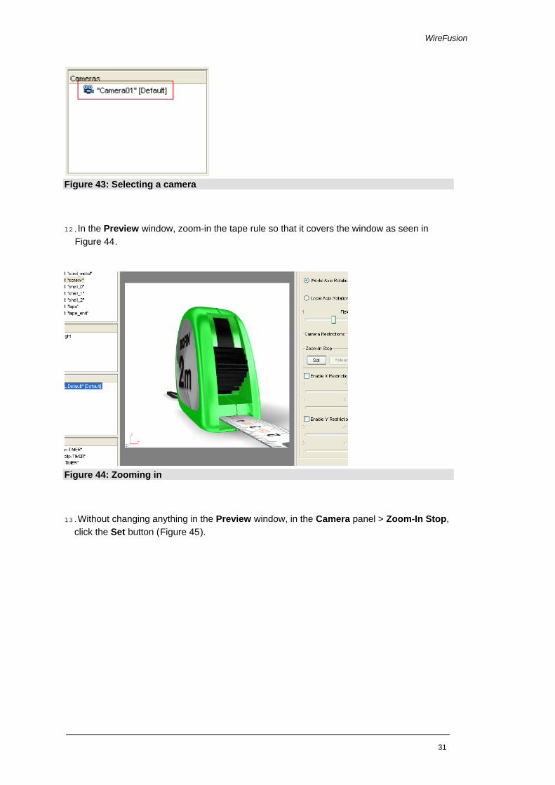
Figure 43: Selecting a camera
12.In the Preview window, zoom-in the tape rule so that it covers the window as seen in Figure 44.
Figure 44: Zooming in
13.Without changing anything in the Preview window, in the Camera panel > Zoom-In Stop, click the Set button (Figure 45).
31

Getting Started – Volume II: 3D Tutorial
Figure 45: Setting the zoom-in stop
14.In the Preview window, zoom-out the tape rule as seen in Figure 46.
Figure 46: Zooming out
15.Without changing anything in the Preview window, in the Camera panel > Zoom-Out Stop, click the Set button.
16.By default, all animations in the 3D scene will automatically start, and loop. To turn off the auto-run, we first have to select all the animations. In the Animations view, select all an-imations (Figure 47).
32

WireFusion
Figure 47: Selecting all animations in the Animations view
17. In the Animation panel, unmark the Loop at Startup checkbox (Figure 48).
Figure 48: The Animation panel
NOTE: You can at any time re-import the 3D model (the VRML file). This is useful e.g. if you have made changes or adjustments in 3ds Max. To do this, click the Replace button in the toolbar. In most situations the Replace function preserves all the parameters, but if you create new Multi/Sub Object materials the Replace function will not operate correctly. In those cases, uncheck the Keep old Object settings.
18. We are ready for now in the 3D Scene dialog. Click the OK button at the bottom of the dialog to close it. Position the 3D Scene Target Area in (0,0). This is done in the Proper-ties view > Target Area (Figure 49)
33
Getting Started – Volume II: 3D Tutorial
Figure 49: Setting X and Y position
Interface We will now set up the basic look and interface for our presentation.
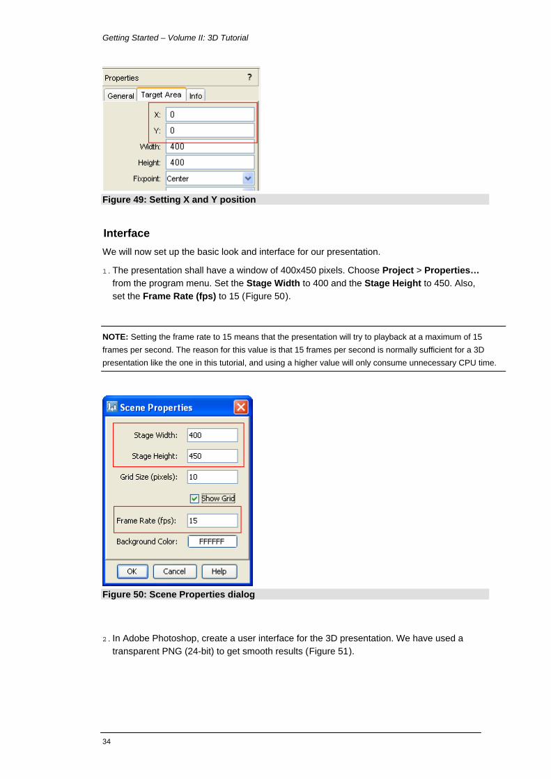
1. The presentation shall have a window of 400x450 pixels. Choose Project > Properties… from the program menu. Set the Stage Width to 400 and the Stage Height to 450. Also, set the Frame Rate (fps) to 15 (Figure 50).
NOTE: Setting the frame rate to 15 means that the presentation will try to playback at a maximum of 15 frames per second. The reason for this value is that 15 frames per second is normally sufficient for a 3D presentation like the one in this tutorial, and using a higher value will only consume unnecessary CPU time.
Figure 50: Scene Properties dialog
2. In Adobe Photoshop, create a user interface for the 3D presentation. We have used a transparent PNG (24-bit) to get smooth results (Figure 51).
34

WireFusion
Figure 51: Creating user interface in Photoshop
3. In WireFusion, insert an Image object. Load the user interface image 'nav.png':
[Path]/My Documents/WireFusion/resources/tutorials/tape_rule/nav.png
4. Rename 'Image 1' to 'Navigation' and position the image in (0,294) (Figure 52).
Figure 52: Navigation image inserted
5. Insert an Image object. Load the background image 'background.png':
35

Getting Started – Volume II: 3D Tutorial
[WireFusion Path]/resources/tutorials/tape_rule/background.png
6. Rename 'Image 1' to 'Background' and position the image in (0,0).
7. Reorder the layers in the Layers view. Position the 'Background' in the bottom layer. Un-mark the Activate checkbox and select the Stamp Background checkbox (Figure 53).
Figure 53: Changing the layer order
NOTE: The Background image will be static in your presentation and will not cover any moving graphics. Therefore you will save CPU time and increase the performance by deactivating the image and by stamping it in the background.
Navigation We normally use the mouse for navigating a 3D scene. However, in this presentation will give the user the option to use navigation buttons for rotating the scene.
•
TIP: Remember to save your project from time to time.
1. From the Objects > Widgets folder, insert a Button object. When the Button dialog opens, select the Advanced Mode checkbox. This allows you to load your own button graphics. In the Up panel, click the Change Graphics… button and load 'up1.png' (Figure 54):
[Path]/My Documents/WireFusion/resources/tape_rule/button_up1.png
36

WireFusion
Figure 54: The Button dialog
2. Still in the Button dialog, in the Down panel, select the Enable checkbox. Click the Change Graphics… button and load 'button_up2.png' (Figure 55). Click OK to close the Button dia-log.
Figure 55: The Button dialog
3. Rename 'Button 1' to 'Up'.
4. Insert a second Button object. In the Up panel, load 'button_down1.png'. In the Down panel, load 'button_down2.png'. Click OK to close the dialog.
5. Rename 'Button 1' to 'Down'.
37

Getting Started – Volume II: 3D Tutorial
6. Insert a third Button object. In the Up panel, load 'button_left1.png'. In the Down panel, load 'button_left2.png'. Click OK to close the dialog.
7. Rename 'Button 1' to 'Left'.
8. Insert a fourth Button object. In the Up panel, load 'button_right1.png'. In the Down panel, load 'button_right2.png'. Click OK to close the dialog.
9. Rename 'Button 1' to 'Right'.
10.Insert a fifth Button object. In the Up panel, load 'button_reset1.png'. In the Down panel, load 'button_reset2.png'. Click OK to close the dialog.
11.Rename 'Button 1' to 'Reset'.
12.Insert a sixth Button object. In the Up panel, load 'button_labels1.png'. In the Down panel, load 'button_labels2.png'. Click OK to close the dialog.
13.Rename 'Button 1' to 'Labels'.
14.Position the Target Areas for the Button objects as follows (Figure 56):
• 'Up' at X:39 and Y:389
• 'Down' at X:39 and Y:423
• 'Left' at X:21 and Y:407
• 'Right' at X:55 and Y:407
• 'Reset' at X:100 and Y:395
• 'Labels' at X:164 and Y:390
Figure 56: Button objects re-positioned
38

WireFusion
15.Connect (Figure 57):
• 'Up' > Out-ports > Button Clicked to '3D Scene 1' > In-ports > Navigation > Rotate > -X
• 'Down' > Out-ports > Button Clicked to '3D Scene 1' > In-ports > Navigation > Rotate > X
• 'Left' > Out-ports > Button Clicked to '3D Scene 1' > In-ports > Navigation > Rotate > -Y
• 'Right' > Out-ports > Button Clicked to '3D Scene 1' > In-ports > Navigation > Rotate > Y
TIP: Remember to use the Wire Creator when connecting objects. It speeds up the wiring process a lot.
Figure 57: Button objects connected to the 3D Scene object
16.For each navigation button; 'Up', 'Down', 'Left' and 'Right', in the Properties view, set the Repeat rate to 50 (Figure 58). This means that the Button object will send out 50 events per second when the button is clicked (and held). Change this value if you want to adjust the rotation speed.
39

Getting Started – Volume II: 3D Tutorial
Figure 58: Setting the button repeat rate
17.Press F7 to preview the presentation. You should now be able to use the navigation but-tons to rotate the tape rule.
Reset Camera We want to be able to reset the camera view in our presentation. There is an option in Wire-Fusion that allows you to have a glide (animation) from the current view to a preset camera view.
1. Open the 3D Scene dialog. Select 'Camera01' in the Cameras view, then open the Cam-era panel. In the Camera Animation section, set the Speed to 1500 (Figure 59). Click OK to close the 3D Scene dialog.
Figure 59: Setting the camera animation speed
40

WireFusion
NOTE: The camera animation speed, i.e. the speed with which the camera glides from the current view to a predefined view, depends on the size of your 3D scene. Therefore you might get different results on different 3D scenes, and you might need to try your way out.
2. Connect (Figure 60):
• 'Reset' > Out-ports > Button Clicked to '3D Scene 1' > In-ports > Camera > Set ''Camera01''
Figure 60: Reseting the camera view
3. Press F7 to preview the presentation. You should now be able to reset the camera by click-ing the Reset button.
Touch Sensors Our 3D scene contains animations and we will trigger those animations by clicking on touch sensors. Any object (shape) in your 3D model can be configured to be a touch sensor. This is done in the 3D Scene dialog. In our presentation we will have three touch sensors; the belt clip, the button, and the tape end.
1. Open the 3D Scene dialog. Select 'belt_clip_0' in the Objects view, then open the Object panel. Select the Show Touchsensor Ports checkbox and the Enable Touchsensor checkbox (Figure 61).
41

Getting Started – Volume II: 3D Tutorial
Figure 61: Making a touch sensor of the belt clip shape
2. Select 'button' in the Objects view, then open the Object panel. Select the Show Touch-
sensor Ports checkbox and the Enable Touchsensor checkbox.
3. Select 'tape_end' in the Objects view, then open the Object panel. This time, select only the Show Touchsensor Ports checkbox, and not the Enable Touchsensor checkbox. Click OK to close the 3D Scene dialog.
New in- and out-ports, for the newly created touch sensors, will now be available in the 3D Scene object (Figure 62). Both the 'belt_clip_0' and the 'button' touch sensors are enabled at presentation startup, while the 'tape_end' touch sensor is disabled.
Figure 62: New touch sensor out-ports added
42

WireFusion
Animations I – Simple Logic In the previous section we created touch sensors, which we will use to trigger our animations with. In this first animation section we will trigger and run the belt clip animation using a rather simple logic.
The logical scheme looks like this:
• Click the 'belt_clip_0' touch sensor with the mouse, which triggers a Progressor object to run.
• The Progressor object runs and counts from 0 to 100 in 1 second.
• The numbers (0-100) from the Progressor is sent to the 3D Scene object and runs the animation.
1. From the Objects > Logic folder, insert a Progressor object. When the Progressor dialog opens, select the Advanced Mode checkbox. Keep the default values, but change the At Startup option to Do nothing, and select the third Output Curve option by marking its ra-diobutton (Figure 63).
Figure 63: Progressor dialog
2. Rename 'Progressor 1' to 'Run belt_clip animation'.
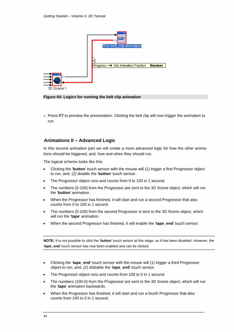
3. Connect (Figure 64):
• '3D Scene 1' > Out-ports > Touch Sensors > ''belt_clip_0'' > Mouse Press to 'Run belt_clip animation' > In-ports > Run
• 'Run belt_clip animation' > Out-ports > Progress [Number] to '3D Scene 1' > In-ports > Animations > ''belt_clip-TIMER'' > Set Animation Fraction [Num-ber]
43
Getting Started – Volume II: 3D Tutorial
Figure 64: Logics for running the belt clip animation
4. Press F7 to preview the presentation. Clicking the belt clip will now trigger the animation to run.
Animations II – Advanced Logic In this second animation part we will create a more advanced logic for how the other anima-tions should be triggered, and, how and when they should run.
The logical scheme looks like this:
• Clicking the 'button' touch sensor with the mouse will (1) trigger a first Progressor object to run, and, (2) disable the 'button' touch sensor.
• The Progressor object runs and counts from 0 to 100 in 1 second.
• The numbers (0-100) from the Progressor are sent to the 3D Scene object, which will run the 'button' animation.
• When the Progressor has finished, it will start and run a second Progressor that also counts from 0 to 100 in 1 second.
• The numbers (0-100) from the second Progressor is sent to the 3D Scene object, which will run the 'tape' animation.
• When the second Progressor has finished, it will enable the 'tape_end' touch sensor.
NOTE: It is not possible to click the 'button' touch sensor at this stage, as it has been disabled. However, the 'tape_end' touch sensor has now been enabled and can be clicked.
• Clicking the 'tape_end' touch sensor with the mouse will (1) trigger a third Progressor object to run, and, (2) disbable the 'tape_end' touch sensor.
• The Progressor object runs and counts from 100 to 0 in 1 second.
• The numbers (100-0) from the Progressor are sent to the 3D Scene object, which will run the 'tape' animation backwards.
• When the Progressor has finished, it will start and run a fourth Progressor that also counts from 100 to 0 in 1 second.
44
WireFusion
45
• The numbers (100-0) from the fourth Progressor is sent to the 3D Scene object, which will run the 'button' animation backwards.
• When the fourth Progressor has finished, it will enable the 'button' touch sensor.
1. Insert two Progressor objects. For both Progressor objects, keep the default values, but change the At Startup option to Do nothing.
2. Rename:
• 'Progressor 1' to 'Run button animation - up'
• 'Progressor 2' to 'Run tape animation - in'
3. Connect (Figure 65):
• '3D Scene 1' > Out-ports > Touch Sensors > ''button'' > Mouse Press to 'Run button animation - up' > In-ports > Run
• '3D Scene 1' > Out-ports > Touch Sensors > ''button'' > Mouse Release to '3D Scene 1' > In-ports > Touch Sensors > ''button'' > Disable
• 'Run button animation - up' > Out-ports > Progress [Number] to '3D Scene 1' > In-ports > Animations > ''button-TIMER'' > Set Animation Fraction [Num-ber]
• 'Run button animation - up' > Out-ports > Finished to 'Run tape animation - in' > In-ports > Run
• 'Run tape animation - in' > Out-ports > Progress [Number] to '3D Scene 1' > In-ports > Animations > ''tape-TIMER'' > Set Animation Fraction [Number]
• 'Run tape animation - in' > Out-ports > Finished to '3D Scene 1' > In-ports > Touch Sensors > ''tape_end'' > Enable
Getting Started – Volume II: 3D Tutorial
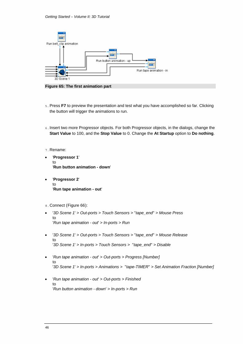
Figure 65: The first animation part
5. Press F7 to preview the presentation and test what you have accomplished so far. Clicking the button will trigger the animations to run.
6. Insert two more Progressor objects. For both Progressor objects, in the dialogs, change the Start Value to 100, and the Stop Value to 0. Change the At Startup option to Do nothing.
7. Rename:
• 'Progressor 1' to 'Run button animation - down'
• 'Progressor 2' to 'Run tape animation - out'
8. Connect (Figure 66):
• '3D Scene 1' > Out-ports > Touch Sensors > ''tape_end'' > Mouse Press to 'Run tape animation - out' > In-ports > Run
• '3D Scene 1' > Out-ports > Touch Sensors > ''tape_end'' > Mouse Release to '3D Scene 1' > In-ports > Touch Sensors > ''tape_end'' > Disable
• 'Run tape animation - out' > Out-ports > Progress [Number] to '3D Scene 1' > In-ports > Animations > ''tape-TIMER'' > Set Animation Fraction [Number]
• 'Run tape animation - out' > Out-ports > Finished to 'Run button animation - down' > In-ports > Run
46

WireFusion
• 'Run button animation - down' > Out-ports > Progress [Number] to '3D Scene 1' > In-ports > Animations > ''button-TIMER'' > Set Animation Fraction [Num-ber]
• 'Run button animation - down' > Out-ports > Finished to '3D Scene 1' > In-ports > Touch Sensors > ''button'' > Enable
Figure 66: The animation logic ready
9. Press F7 to preview the presentation. Try first to click the button, which will release the lock and have the tape moving in. Then, try to click the end of the tape, which will move the tape out again and then lock it by moving the button down.
47

Getting Started – Volume II: 3D Tutorial
Adding Hotspot Labels We will point out the hotspots (the touch sensors) in our presentation and will briefly describe what they do by showing a label next to them (Figure 67).
Figure 67: Hotspot labels added
1. Insert an Image object. Load the image 'arrows.png':
[Path]/My Documents/WireFusion/resources/tape_rule/arrows.png
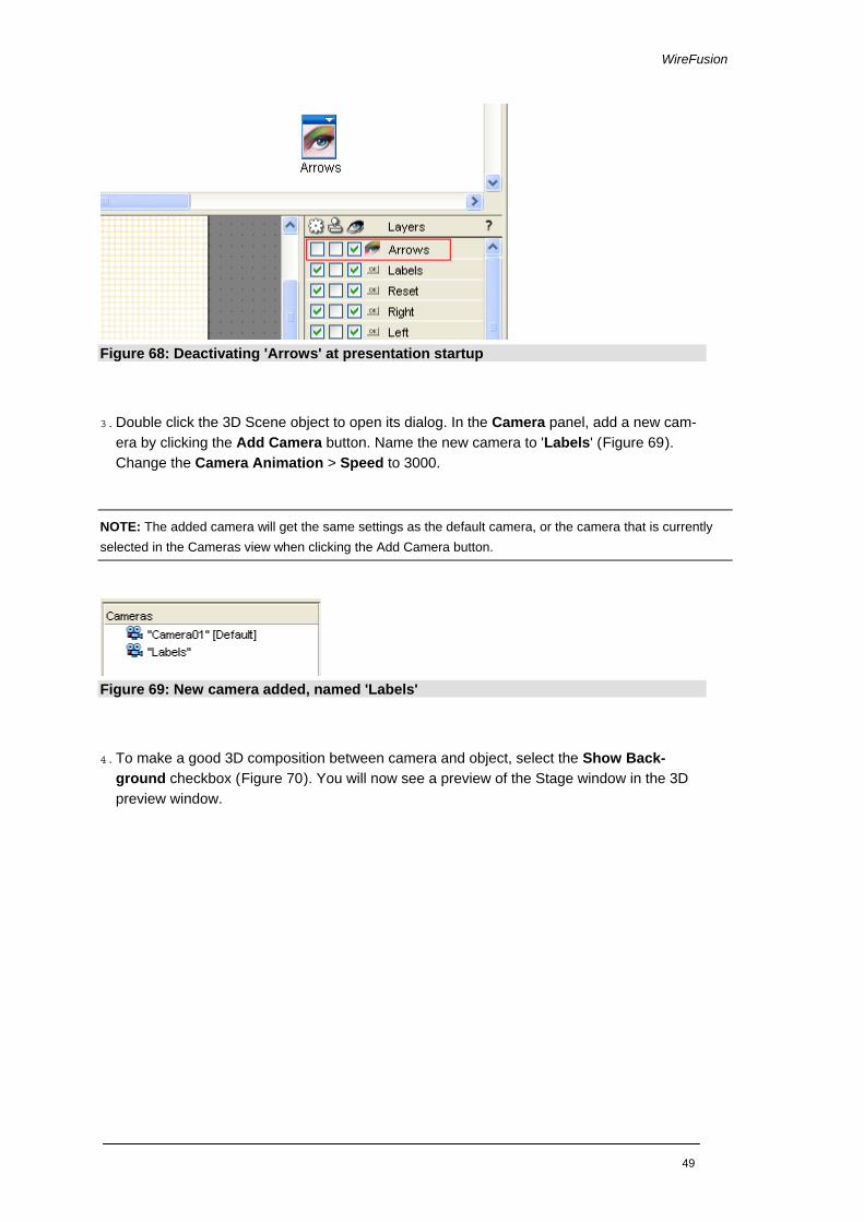
2. Rename 'Image 1' to 'Arrows', position the image in (0,0) and disable it by unmarking the Activate checkbox in the Layers view (Figure 68).
48
WireFusion
Figure 68: Deactivating 'Arrows' at presentation startup
3. Double click the 3D Scene object to open its dialog. In the Camera panel, add a new cam-era by clicking the Add Camera button. Name the new camera to 'Labels' (Figure 69). Change the Camera Animation > Speed to 3000.
NOTE: The added camera will get the same settings as the default camera, or the camera that is currently selected in the Cameras view when clicking the Add Camera button.
Figure 69: New camera added, named 'Labels'
4. To make a good 3D composition between camera and object, select the Show Back-ground checkbox (Figure 70). You will now see a preview of the Stage window in the 3D preview window.
49

Getting Started – Volume II: 3D Tutorial
Figure 70: Making the stage graphics visible in the 3D Scene preview
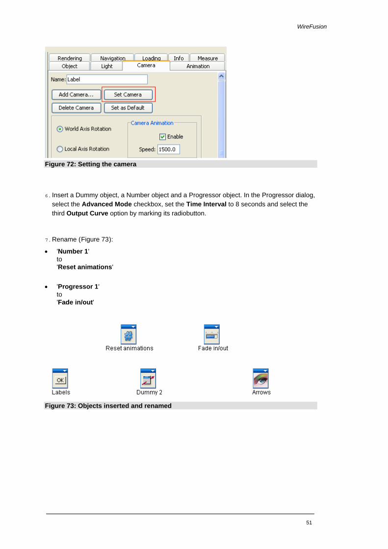
5. Use the mouse to rotate, zoom and pan the object into the right position (Figure 71). When you are satisfied, click the Set Camera button (Figure 72). Click the OK button to close the 3D Scene dialog.
Figure 71: Positioning the object
50
WireFusion
Figure 72: Setting the camera
6. Insert a Dummy object, a Number object and a Progressor object. In the Progressor dialog, select the Advanced Mode checkbox, set the Time Interval to 8 seconds and select the third Output Curve option by marking its radiobutton.
7. Rename (Figure 73):
• 'Number 1' to 'Reset animations'
• 'Progressor 1' to 'Fade in/out'
Figure 73: Objects inserted and renamed
51

Getting Started – Volume II: 3D Tutorial
8. When the Labels button is clicked, send a pulse to the Dummy object.
Connect (Figure 74):
• 'Labels' > Out-ports > Button Clicked to 'Dummy 1' > In-ports > Push Pulse
NOTE: The Dummy object works as a repeater, and only passes on the pulse coming from the Button object. We could optionally have connected the Button object directly to the other objects if we wanted, but the bene-fit of using the Dummy object in between is that we can then trigger the same function from elsewhere.
Figure 74: Sending a pulse to the Dummy object
9. From the Dummy object, have the 'Arrows' image activated and faded in.
Connect (Figure 75):
• 'Dummy 1' > Out-ports > Pulse Pushed to 'Arrows' > In-ports > Activate
• 'Dummy 1' > Out-ports > Pulse Pushed to 'Fade in/out' > In-ports > Run
• 'Fade in/out' > Out-ports > Progress [Number] to 'Arrows' > In-ports > Set Opacity [Number]
Figure 75: Activating and fading in the Image object
52
WireFusion
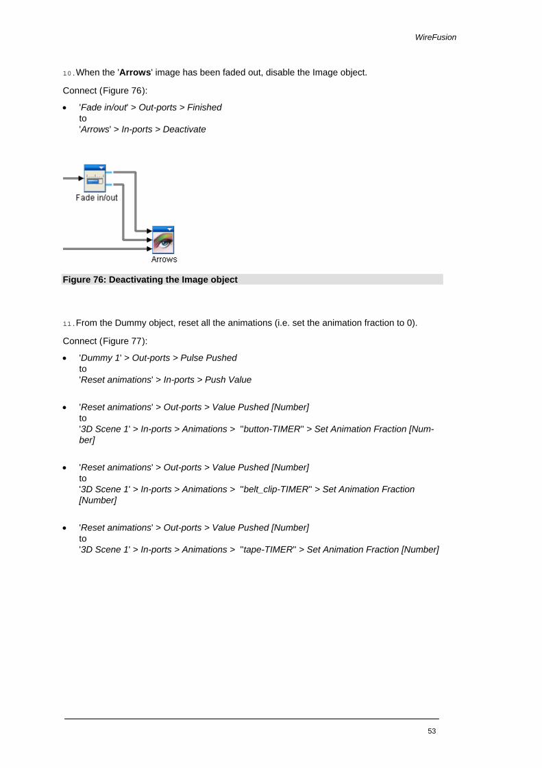
10.When the 'Arrows' image has been faded out, disable the Image object.
Connect (Figure 76):
• 'Fade in/out' > Out-ports > Finished to 'Arrows' > In-ports > Deactivate
Figure 76: Deactivating the Image object
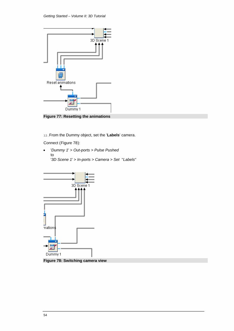
11.From the Dummy object, reset all the animations (i.e. set the animation fraction to 0).
Connect (Figure 77):
• 'Dummy 1' > Out-ports > Pulse Pushed to 'Reset animations' > In-ports > Push Value
• 'Reset animations' > Out-ports > Value Pushed [Number] to '3D Scene 1' > In-ports > Animations > ''button-TIMER'' > Set Animation Fraction [Num-ber]
• 'Reset animations' > Out-ports > Value Pushed [Number] to '3D Scene 1' > In-ports > Animations > ''belt_clip-TIMER'' > Set Animation Fraction [Number]
• 'Reset animations' > Out-ports > Value Pushed [Number] to '3D Scene 1' > In-ports > Animations > ''tape-TIMER'' > Set Animation Fraction [Number]
53
Getting Started – Volume II: 3D Tutorial
Figure 77: Resetting the animations
12.From the Dummy object, set the 'Labels' camera.
Connect (Figure 78):
• 'Dummy 1' > Out-ports > Pulse Pushed to '3D Scene 1' > In-ports > Camera > Set ''Labels''
Figure 78: Switching camera view
54

WireFusion
13.From the Dummy object, disable the 3D rendering by switching to Pause mode.
Connect (Figure 79):
• 'Dummy 1' > Out-ports > Pulse Pushed to '3D Scene 1' > In-ports > Pause
NOTE: Pause mode temporarily stops the 3D rendering, making it impossible to interact with the model. The Pause mode can also be used when you want to show, for example, animations in front or behind the 3D, as the 3D will not consume any CPU while paused.
Figure 79: Switching to Pause mode
14.From the Dummy object, reset the touch sensors to their initial states.
Connect (Figure 80):
• 'Dummy 1' > Out-ports > Pulse Pushed to '3D Scene 1' > In-ports > Touch Sensors > ''button'' > Enable
• 'Dummy 1' > Out-ports > Pulse Pushed to '3D Scene 1' > In-ports > Touch Sensors > ''tape_end'' > Enable
55

Getting Started – Volume II: 3D Tutorial
Figure 80: Resetting the touch sensors
15.When the 'Arrows' image has been faded out, set the 'Camera01' camera.
Connect (Figure 81):
• 'Fade in/out' > Out-ports > Finished to '3D Scene 1' > In-ports > Camera > Set ''Camera01''
Figure 81: Setting the default camera
16.When the 'Arrows' image has been faded out, enable the 3D rendering again by resuming it.
Connect (Figure 82):
• 'Fade in/out' > Out-ports > Finished to '3D Scene 1' > In-ports > Resume
56

WireFusion
Figure 82: Resuming from Pause mode
17.Press F7 to preview the presentation. Click the Labels button to test the newly added func-tion.
18.Press CTRL+F7 to preview the presentation in your default web browser. Make sure all function and features are working.
Optimize Project Before saving and publishing the project we will clean it up a bit, making it easier to navigate and to read the project.
1. Insert a Scene object. On the question to have a Target Area for your Scene object, an-swer Yes (Figure 83), then rename the object from 'Scene 1' to 'Buttons'.
Figure 83: Choosing to have a Target Area
2. Select all Button objects with the mouse (Figure 84). Press SHIFT on your keyboard and drag and drop the objects on the ‘Buttons’ object in order to group them.
57

Getting Started – Volume II: 3D Tutorial
Figure 84: Selecting objects to be grouping in the Buttons object
3. Double click the ‘Buttons’ Scene object to open it up. Then click the Stage tab to see the entire Stage window (Figure 85).
Figure 85: Switch tab
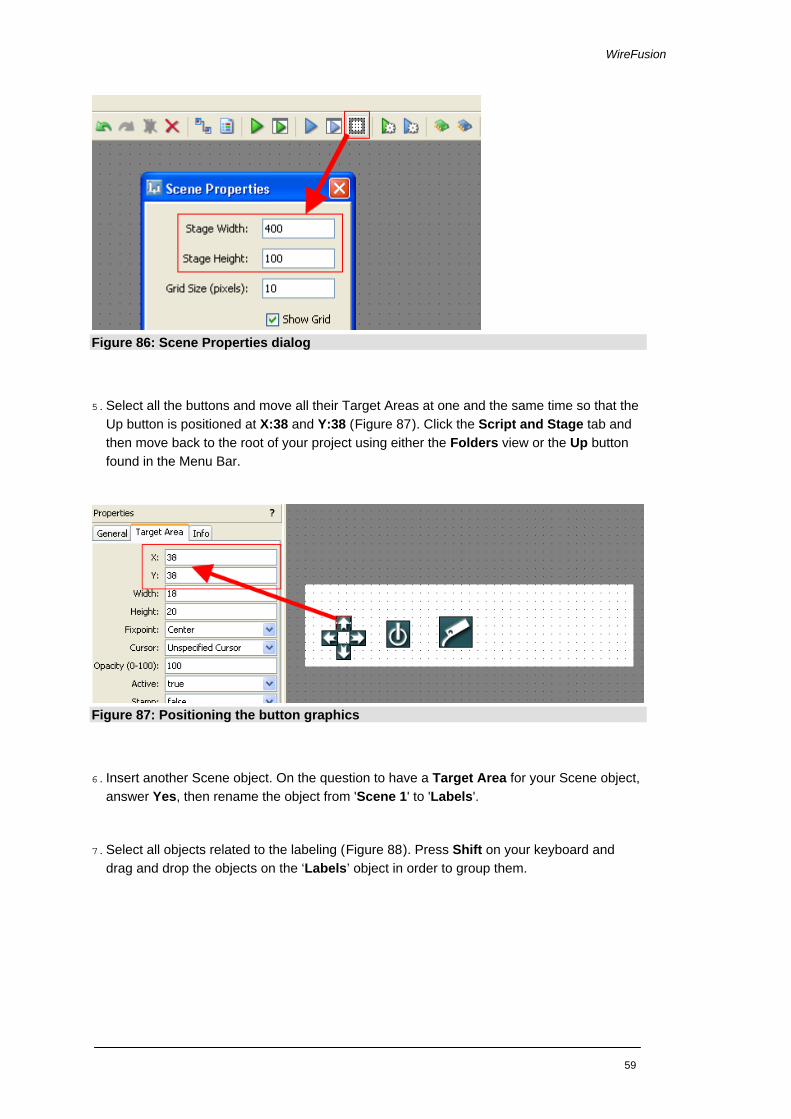
4. Click the Scene Properties button in the Menu Bar to open its dialog. Set the Stage Width
to 400 and the Stage Height to 100 (Figure 86). Click OK to close.
58
WireFusion
Figure 86: Scene Properties dialog
5. Select all the buttons and move all their Target Areas at one and the same time so that the Up button is positioned at X:38 and Y:38 (Figure 87). Click the Script and Stage tab and then move back to the root of your project using either the Folders view or the Up button found in the Menu Bar.
Figure 87: Positioning the button graphics
6. Insert another Scene object. On the question to have a Target Area for your Scene object, answer Yes, then rename the object from 'Scene 1' to 'Labels'.
7. Select all objects related to the labeling (Figure 88). Press Shift on your keyboard and drag and drop the objects on the ‘Labels’ object in order to group them.
59

Getting Started – Volume II: 3D Tutorial
Figure 88: Selecting objects to be grouping in the Labels object
8. Double click the ‘Labels’ Scene object to open it up. Click the Scene Properties button in
the Menu Bar to open its dialog. Set the Stage Width to 400 and the Stage Height to 100. Click OK to close. Move back to the root of your project using either the Folders view or the Up button found in the Menu Bar (Figure 89).
Figure 89: The grouping objects
9. Position the ‘Labels’ object at X:0 and at Y:0.
10.Insert a Folder object and rename it from 'Folder 1' to 'Animations'.
60
WireFusion
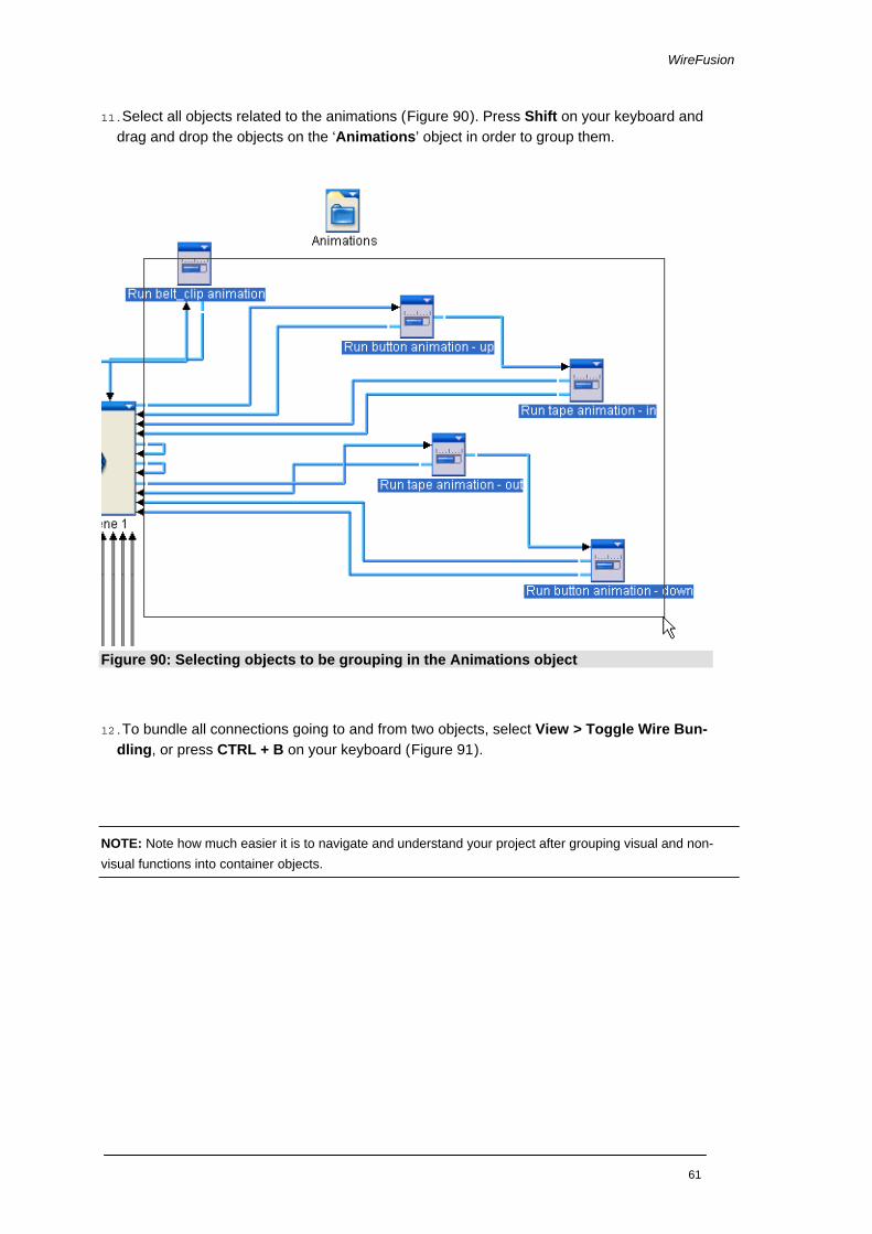
11.Select all objects related to the animations (Figure 90). Press Shift on your keyboard and drag and drop the objects on the ‘Animations’ object in order to group them.
Figure 90: Selecting objects to be grouping in the Animations object
12.To bundle all connections going to and from two objects, select View > Toggle Wire Bun-dling, or press CTRL + B on your keyboard (Figure 91).
NOTE: Note how much easier it is to navigate and understand your project after grouping visual and non-visual functions into container objects.
61

Getting Started – Volume II: 3D Tutorial
Figure 91: Bundled wires
Publish We are ready with our presentation and will now publish it. We have different options for pub-lishing a WireFusion presentation, however, in this tutorial we will publish it as a Java Applet, as we want it to run on a web page.
1. Choose File > Publish…
2. When the Publish dialog opens, choose a name for the presentation and a folder to publish it to. Choose the name 'My_tape_rule' (Figure 92).
Figure 92: Choosing name and location to publish the presentation
3. Make sure the Format is set to Java Applet. You can optionally also select the Download Java Plug-in if Java is missing checkbox (Figure 93).
Figure 93: Publishing the presentation as a Java Applet
62

WireFusion
NOTE: You can optionally choose to encrypt your resources by marking the Encrypt resource file option. This prevents other users from stealing your resources. Not available in the Standard edition.
4. Change the default loading graphics by marking the Custom Loader Graphics checkbox (Figure 94). Change the default Progress Bar Graphics, by clicking the Change… button. Load the image 'loading_bar.gif':
[Path]/My Documents/WireFusion/resources/tape_rule/loading_bar.gif
NOTE: The Custom Loader Graphics option is not available in the Standard edition.
5. Change the default Background Graphics, by clicking the Change… button. Load the image 'loading_background.gif':
[Path]/My Documents/WireFusion/resources/tape_rule/loading_background.gif
Figure 94: Changing loading graphics
6. Click Finish to publish the presentation. A dialog opens confirming that the presentation has been published. In the dialog, click the Open Folder button to go directly to your pub-lished presentation (Figure 95).
Figure 95: Publishing confirmed
7. Test the presentation by double clicking the HTML file. Your default browser should open and display the presentation.
63
Getting Started – Volume II: 3D Tutorial
Part III
HTML Editing in Dreamweaver The final step in this tutorial is to insert the published presentation into a HTML file of your choice, and, to upload the presentation to a web server. We use Adobe Dreamweaver, but any HTML editor and FTP client can be used.
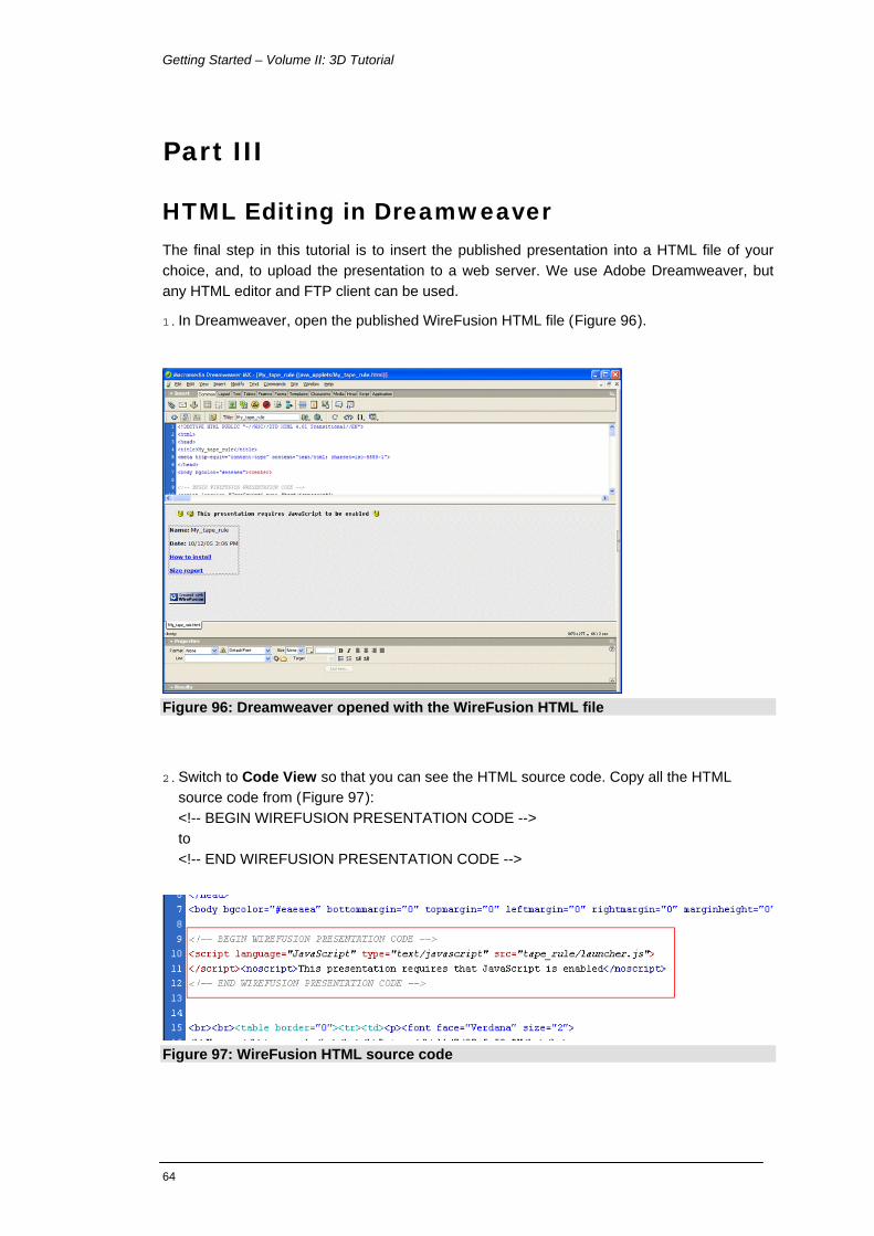
1. In Dreamweaver, open the published WireFusion HTML file (Figure 96).
Figure 96: Dreamweaver opened with the WireFusion HTML file
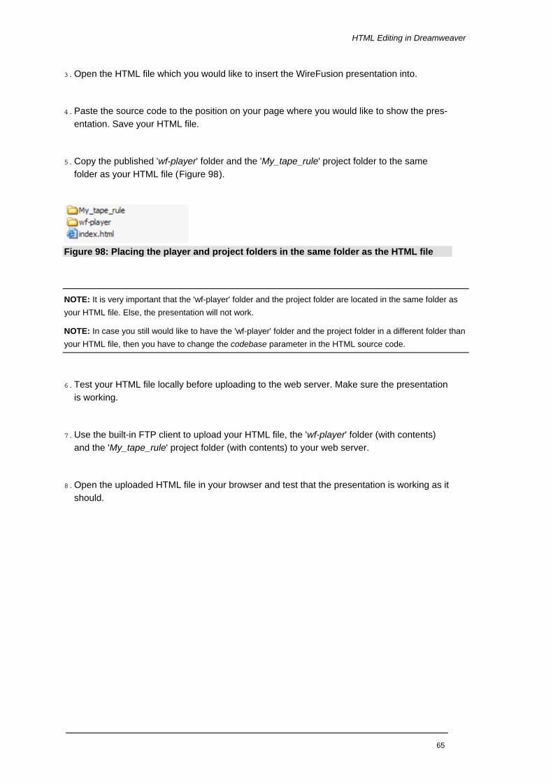
2. Switch to Code View so that you can see the HTML source code. Copy all the HTML source code from (Figure 97): <!-- BEGIN WIREFUSION PRESENTATION CODE --> to <!-- END WIREFUSION PRESENTATION CODE -->
Figure 97: WireFusion HTML source code
64
HTML Editing in Dreamweaver
3. Open the HTML file which you would like to insert the WireFusion presentation into.
4. Paste the source code to the position on your page where you would like to show the pres-entation. Save your HTML file.
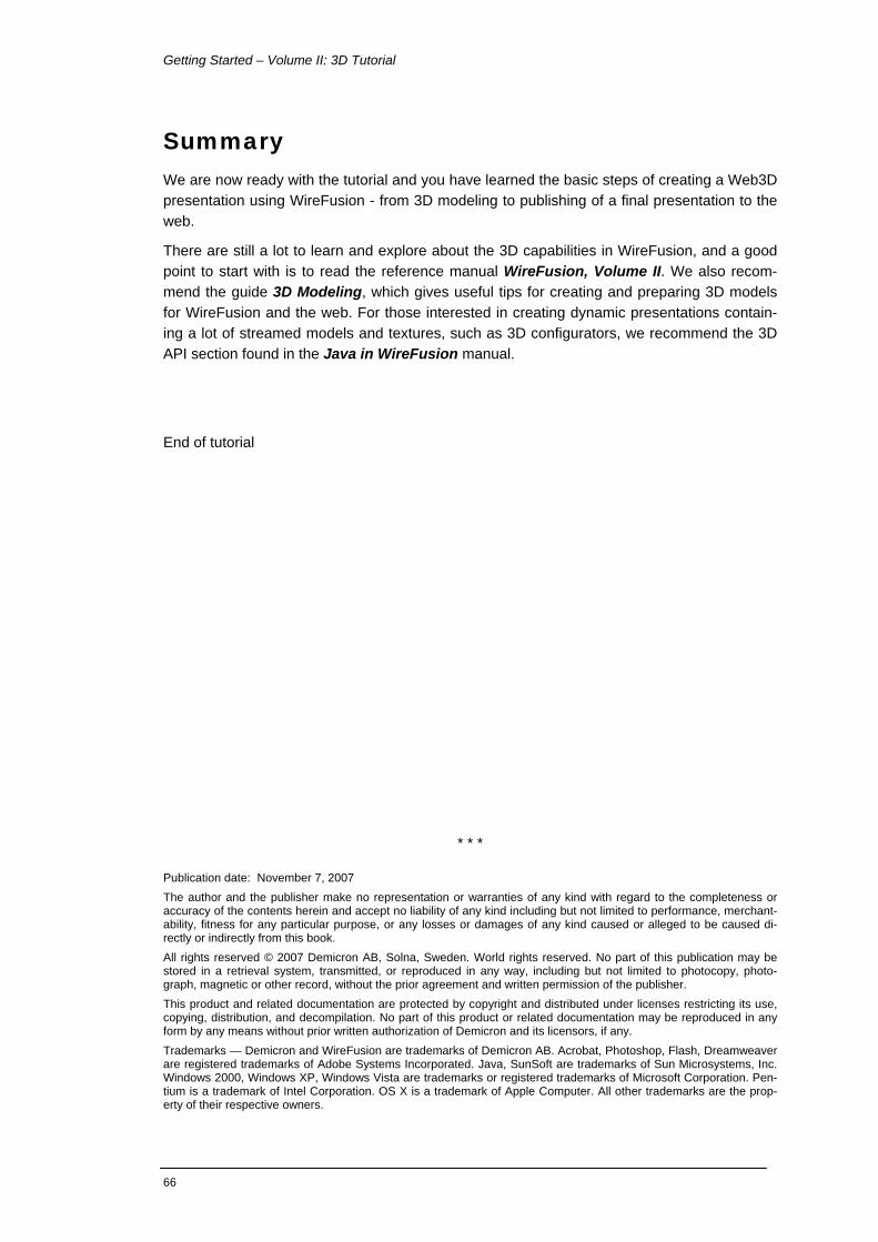
5. Copy the published 'wf-player' folder and the 'My_tape_rule' project folder to the same folder as your HTML file (Figure 98).
Figure 98: Placing the player and project folders in the same folder as the HTML file
NOTE: It is very important that the 'wf-player' folder and the project folder are located in the same folder as your HTML file. Else, the presentation will not work.
NOTE: In case you still would like to have the 'wf-player' folder and the project folder in a different folder than your HTML file, then you have to change the codebase parameter in the HTML source code.
6. Test your HTML file locally before uploading to the web server. Make sure the presentation is working.
7. Use the built-in FTP client to upload your HTML file, the 'wf-player' folder (with contents) and the 'My_tape_rule' project folder (with contents) to your web server.
8. Open the uploaded HTML file in your browser and test that the presentation is working as it should.
65
Getting Started – Volume II: 3D Tutorial
66
Summary We are now ready with the tutorial and you have learned the basic steps of creating a Web3D presentation using WireFusion - from 3D modeling to publishing of a final presentation to the web.
There are still a lot to learn and explore about the 3D capabilities in WireFusion, and a good point to start with is to read the reference manual WireFusion, Volume II. We also recom-mend the guide 3D Modeling, which gives useful tips for creating and preparing 3D models for WireFusion and the web. For those interested in creating dynamic presentations contain-ing a lot of streamed models and textures, such as 3D configurators, we recommend the 3D API section found in the Java in WireFusion manual.
End of tutorial
* * * Publication date: November 7, 2007 The author and the publisher make no representation or warranties of any kind with regard to the completeness or accuracy of the contents herein and accept no liability of any kind including but not limited to performance, merchant-ability, fitness for any particular purpose, or any losses or damages of any kind caused or alleged to be caused di-rectly or indirectly from this book. All rights reserved © 2007 Demicron AB, Solna, Sweden. World rights reserved. No part of this publication may be stored in a retrieval system, transmitted, or reproduced in any way, including but not limited to photocopy, photo-graph, magnetic or other record, without the prior agreement and written permission of the publisher. This product and related documentation are protected by copyright and distributed under licenses restricting its use, copying, distribution, and decompilation. No part of this product or related documentation may be reproduced in any form by any means without prior written authorization of Demicron and its licensors, if any. Trademarks — Demicron and WireFusion are trademarks of Demicron AB. Acrobat, Photoshop, Flash, Dreamweaver are registered trademarks of Adobe Systems Incorporated. Java, SunSoft are trademarks of Sun Microsystems, Inc. Windows 2000, Windows XP, Windows Vista are trademarks or registered trademarks of Microsoft Corporation. Pen-tium is a trademark of Intel Corporation. OS X is a trademark of Apple Computer. All other trademarks are the prop-erty of their respective owners.