getting started with ni 7340/7350 motion controllers and ... · getting started with ni 7340/7350...
TRANSCRIPT

Getting Started with NI 7340/7350 Motion Controllers and AKD Servo DrivesThis document explains how to install and configure the AKD servo drives for use with the NI 7340 and NI 7350 motion controllers.
Tip If you encounter any problems during setup, refer to the Tips and Troubleshooting section for assistance.
ContentsWhat You Need to Get Started ................................................................................................. 2
Hardware .......................................................................................................................... 2Software............................................................................................................................ 3Related Documentation .................................................................................................... 4
NI Motion Controller Configuration and Installation............................................................... 5Step 1: Install NI-Motion.................................................................................................. 5Step 2: Install the NI 7340/7350 Motion Controller......................................................... 5Step 3: Install Software on and Configure the
RT PXI Controller (PXI 7340/7350 Only).................................................................... 7NI UMI and AKD Servo Drive Configuration and Installation ............................................... 8
Step 1: Connect and Configure the NI UMI..................................................................... 8Step 2: Mount the Drive and Connect the Protective Earth ............................................. 14Step 3: Connect the NI UMI to AKD Cable to the AKD Servo Drive............................. 15Step 4: Connect the Logic Power Supply to the AKD Servo Drive................................. 16Step 5: Connect the Motor and Encoder to the Drive....................................................... 19Step 6: Connect the AC Input Power................................................................................ 20Step 7: Connect the Drive Communication...................................................................... 21Step 8: Confirm Drive Connections ................................................................................. 22
Software Installation and Configuration................................................................................... 23Step 1: Update Firmware on the Motion Controller......................................................... 23Step 2: Configure the NI Motion Controller .................................................................... 23Step 3: Install AKD WorkBench and Configure the Drive .............................................. 25Step 4: Test the Motor In MAX........................................................................................ 33
Tips and Troubleshooting......................................................................................................... 34The Drive Does Not Enable.............................................................................................. 34Cannot Communicate With the Drive Using Ethernet ..................................................... 34UMI-7772/74 Does Not Turn On ..................................................................................... 34Drive Does Not Turn On .................................................................................................. 34Connecting to the PC Using a Static IP............................................................................ 34

2 | ni.com | Getting Started with NI 7340/7350 Controllers and AKD Drives
The Motor Responds Poorly .............................................................................................35Using an EtherCAT AKD Drive in Analog Mode ...........................................................35Cannot See the AKD Servo Drive in the AKD WorkBench Software.............................36
Wiring Diagram ........................................................................................................................37Worldwide Support and Services .............................................................................................38
What You Need to Get Started
Caution Before installing the drive, review Chapter 2, Safety, in the AKD Installation Manual that came with your hardware or is available from ni.com/manuals. Failure to follow safety instructions may result in injury or damage to equipment.
You need the following items to get started.
Hardware A computer with an available PXI or PCI slot
NI 7340 or NI 7350 motion controller
UMI-7764 or UMI-7772/74
68-pin cable to connect your NI UMI and motion controller
– UMI-7764—SH68-C68-S
– UMI-7772/74—SHC68-C68-S
UMI to AKD drive cable appropriate for the UMI you are using
+24 VDC power supply for the NI UMI-7772/74 and AKD servo drive
+5 V power supply for the UMI-7764
Ethernet connection and cable for the AKD servo drive
AKD servo drive
NI or third-party servo motor and encoder
Note AKM series servo motors available from NI contain built-in encoders and come pre-wired for use with the AKD servo drive. National Instruments recommends using one of these motors for the best user experience and system performance.
Getting Started with NI 7340/7350 Controllers and AKD Drives | © National Instruments | 3
Software NI-Motion 7.6 or later driver software
One of the following software packages and documentation:
– LabVIEW 8.5 or later
– LabWindows™/CVI™ 8.5 or later
– Microsoft Visual C++
– Microsoft Visual Basic
AKD WorkBench software
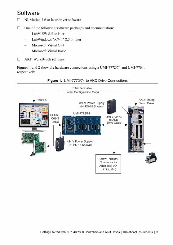
Figures 1 and 2 show the hardware connections using a UMI-7772/74 and UMI-7764, respectively.
Figure 1. UMI-7772/74 to AKD Drive Connections
Host PC
SHC68-C68-SCable
UMI-7772/74 to AKD
Drive Cable
Screw TerminalConnector forAdditional I/O (Limits, etc.)
Ethernet Cable(Initial Configuration Only)
+24 V Power Supply (NI PS-15 Shown)
UMI-7772/74
AKD AnalogServo Drive+24 V Power Supply
(NI PS-15 Shown)

4 | ni.com | Getting Started with NI 7340/7350 Controllers and AKD Drives
Figure 2. UMI-7764 to AKD Drive Connections
Related DocumentationThe following documents contain additional information that you may find helpful. All referenced documents ship with the product and are available at ni.com/manuals.
• NI 7340 User Manual or NI 7350 User Manual—Describes the electrical and mechanical aspects of the NI 7340/7350 motion controller, and contains information about installing and operating the device.
• Getting Started with NI-Motion for NI 73xx Motion Controllers—Provides instructions for installing and getting started with the NI-Motion driver software and NI motion controllers.
• AKD Installation Manual—Provides additional information about the electrical and mechanical aspects of the AKD servo drive, including important safety information and advanced configuration information.
• NI-Motion Help—Contains information about designing a basic move, designing a multi-axis move, incorporating image and data acquisition into motion applications, and working with common motion concepts, such as contouring and breakpoints. This document is task-based and takes you through each phase of designing and executing a motion application.
• NI-Motion Function Help—Contains function reference information for C and Visual Basic and provides details about each function, including a description of the function, a list of the function parameters, illustrations, and error codes.
• NI-Motion VI Help—Contains LabVIEW VI reference information and provides details about each VI, including VI descriptions, lists of VI parameters, usage, illustrations, and error codes.
• Measurement & Automation Explorer Help for Motion—Provides information about using MAX to configure the NI motion controller as well as advanced conceptual information about topics such as Bode analysis and control loop parameters.
Host PC
Ethernet Cable(Initial Configuration Only)
SH68-C68-SCable
+24 V Power Supply (NI PS-15 Shown)
UMI-7764 to AKD Drive Cable
AKD AnalogServo Drive
UMI-7764
+5 V Power Supply
Getting Started with NI 7340/7350 Controllers and AKD Drives | © National Instruments | 5
NI Motion Controller Configuration and Installation
Caution Before installing the NI 7340/7350 motion controller refer to the user manual appropriate to your controller for safety and specification information. Failure to follow safety instructions may result in damage to equipment.
Step 1: Install NI-MotionYou must install the NI-Motion driver software before installing an NI motion controller for the first time. If you are upgrading from a previous version of NI-Motion, it is not necessary to remove the NI motion controller before installing the upgrade. The upgrade does not affect the existing Microsoft Windows configuration.
Note If you are using a Real-Time OS, install LabVIEW Real-Time on the development computer before installing NI-Motion so that the RT support files install.
Complete the following steps to install the NI-Motion driver software:
1. Insert the NI-Motion CD into the CD-ROM drive to display the NI-Motion installation screen.
2. If you have autorun enabled, autorun.exe runs automatically. Otherwise, double-click autorun.exe.
3. Follow the onscreen instructions.
Note You must update the firmware on your NI motion controller(s) before you can use them with the corresponding version of NI-Motion. Refer to Step 1: Update Firmware on the Motion Controller in the Software Installation and Configuration section for detailed instructions.
Step 2: Install the NI 7340/7350 Motion ControllerThe following sections explain how to install PXI and PCI motion controllers.
Note When adding or removing the motion controller, you must be logged on with administrator-level access. After you have restarted the system, you may need to refresh Measurement & Automation Explorer (MAX) to view the new controller.
PXI Controllers1. Power off and unplug the chassis.
Caution To protect yourself and the computer from electrical hazards, the computer must remain unplugged until the installation is complete.

6 | ni.com | Getting Started with NI 7340/7350 Controllers and AKD Drives
2. Choose an unused peripheral slot and remove the filler panel.
3. Touch a metal part on the chassis to discharge any static electricity that might be on your clothes or body. Static electricity can damage the controller.
4. Insert the PXI controller into the chosen slot. Use the injector/ejector handle to fully secure the device into place.
5. Attach the front panel of the PXI controller to the front panel mounting rails of the chassis with the slot screws on the chassis.
Caution Make sure you have correctly connected all safety devices before you power on the motion system. Safety devices include inhibits, limit switches, and emergency shut down circuits.
Caution Always power on the computer containing the motion controller and initialize the controller before you power on the rest of the motion system. Power off the motion system in the reverse order.
6. Plug in and power on the chassis.
PCI Controllers1. Power off and unplug the computer.
Caution To protect yourself and the computer from electrical hazards, the computer must remain unplugged until the installation is complete.
2. Open the computer case to expose access to the PCI expansion slots.
3. Touch a metal part on the chassis to discharge any static electricity that might be on your clothes or body. Static electricity can damage the controller.
4. Choose an unused +3.3 V or +5 V PCI slot, and remove the corresponding expansion slot cover on the back panel of the computer.
5. Gently rock the controller into the slot. The connection may be tight, but do not force the controller into place.
Note Check that the bracket of the device aligns with the hole in the back panel rail of the computer chassis.
6. Secure the mounting bracket of the controller to the back panel rail of the computer.
7. Replace the cover.
Caution Make sure you have correctly connected all safety devices before you power on the motion system. Safety devices include inhibits, limit switches, and emergency shut down circuits.

Getting Started with NI 7340/7350 Controllers and AKD Drives | © National Instruments | 7
Caution Always power on the computer containing the motion controller, and then initialize the controller before you power on the rest of the motion system. Power off the motion system in the reverse order.
8. Plug in and power on the computer.
Step 3: Install Software on and Configure the RT PXI Controller (PXI 7340/7350 Only)
Note This step is only required if you are using a PXI-7340/7350 motion controller and an RT PXI controller. If you are not using an RT PXI controller, skip to the NI UMI and AKD Servo Drive Configuration and Installation section.
Complete the following steps to configure the controller and install software on it.
Note The Measurement & Automation Explorer (MAX) user interface may not match these steps exactly depending on which version of MAX you are using.
1. Boot the NI PXI embedded controller into the real-time operating system. The PXI controller automatically boots into LabVIEW RT Safe Mode when no software is installed. LabVIEW RT Safe Mode loads with the basic real-time operating system and automatically attempts to connect to the network using DHCP. If DHCP is not available, the controller connects to the network with a link-local IP address.
Tip You can connect a monitor to the PXI to display startup messages such as the IP address and MAC address.
2. Launch Measurement & Automation Explorer (MAX) on the development computer by clicking the MAX icon on the desktop ( ), or by selecting Start»All Programs»National Instruments»Measurement & Automation.
3. Expand the Remote Systems branch. MAX lists the PXI controller as the model name of the controller followed by the MAC address (for example, NI-PXI-8104 00802f108562).
Tip Record the PXI controller MAC address, located on the side of the controller, for use in identifying the controller. The label also can be removed and placed on the front of the controller for easier access. If you have connected the PXI controller to a monitor, the MAC address also appears when the PXI system boots up.
4. Select the System Settings tab and type a descriptive name for the system in the Name field.
5. (Optional) Complete this step only if the target has an empty IP address (0.0.0.0). Select the Network Settings tab and select DHCP or Link Local from the Configure IPv4 Address list to assign an IP address or select Static to specify a static IP address in the IPv4 Address section.
6. Click Save on the toolbar and let MAX reboot the system.

8 | ni.com | Getting Started with NI 7340/7350 Controllers and AKD Drives
7. When the new system name appears under Remote Systems, expand the controller item in the tree, right-click Software, and select Add/Remove Software.
8. Install the LabVIEW Real-Time software and NI-Motion on the RT target. Go to ni.com/info and enter etspc for the latest information about supported software.
9. Click Next to install the selected software on the controller. Click Help if you need information about installing recommended software sets.
10. Expand the Devices and Interfaces item under the PXI system.
11. Right-click the remote motion controller icon and select Map to Local Machine. This assigns a local board ID to the remote motion controller in the host system.
Mapping the remote controller into the local system allows you to configure the controller through MAX exactly as you would a controller that is in the host system. You can initialize the controller, download firmware, and use the interactive and configuration panels exactly as you would on a controller installed in the host machine. You also can write VIs using the remote motion controller through the local board ID assigned to it.
This allows you to write and debug your VIs on the host, and then download them to the remote system when you are ready. All you need to change is the board ID in your VI from the locally assigned Board ID to the ID assigned by the remote system.
12. Browse to Devices and Interfaces under My System, where there is a shortcut icon next to a new controller name.
For example, if the motion controller on the remote system is a PXI-7354, and the remote system has an IP address of 123.45.678.9, then the shortcut device would show a name like PXI-7354 (X) on 123.45.678.9 (Y).
X is the board ID assigned to the board by the remote system. Use this board ID for VIs that are downloaded to the remote system through LabVIEW RT.
Y is the board ID assigned to the remote motion controller by the local system. Use this board ID for any VIs that run on the host and use the remote motion controller.
13. Close MAX.
NI UMI and AKD Servo Drive Configuration and InstallationThis section covers the hardware setup for the NI UMI and AKD servo drive.
Step 1: Connect and Configure the NI UMI
Connecting a UMI-7772/74Complete the following steps to connect and configure the UMI-7772/74. If you are using a UMI-7764 refer to the Connecting a UMI-7764 section.
Tip For more information about connecting external power, encoders, and other motion I/O signals to the UMI-7772/74, refer to the National Instruments Universal Motion Interface (UMI)-7772/74 User Manual and Specifications.

Getting Started with NI 7340/7350 Controllers and AKD Drives | © National Instruments | 9
1. Connect the SHC68-C68-S 68-pin shielded cable between the Motion I/O connector on the NI 7340/7350 motion controller and the Motion I/O connector on the UMI-7772/74.
2. Connect the UMI-7772/74 to AKD Drive Cable to the Control and Feedback connectors on the UMI-7772/74.
Figure 3 shows the UMI-7772/74 to AKD Drive Cable connectors.
Figure 3. UMI-7772/74 to AKD Drive Cable Connectors
The UMI-7772/74 to AKD Drive Cable contains the following connections:
• UMI-7772/74 Feedback Connector—25-pin DSUB connector containing encoder, limit, and home sensor signals.
• UMI-7772/74 Control Connector—15-pin DSUB connector containing drive command and drive enable signals.
• X8 10-Pin Connector—10-pin connector containing the servo command, enable, and fault signals.
• X9 DSUB Connector—9-pin DSUB connector containing emulated encoder output signals from the AKD servo drive.
• X1 3-pin Connector—+24 V power supply connection for the AKD servo drive.
• Screw Terminal Connector—20-pin screw terminal connector for external I/O connections. Table 1 shows the UMI-7772/74 to AKD Drive Cable screw terminal pinout.
X9
Screw TerminalConnector
X1 3-Pin Connector
X8 10-Pin Connector
X9 DSUB Connector
UMI-7772/74FeedbackConnector
UMI-7772/74Control
Connector

10 | ni.com | Getting Started with NI 7340/7350 Controllers and AKD Drives
3. Configure the UMI-7772/74 DIP switches. You must set the UMI-7772/74 switches to the following settings to match the polarity configuration for the AKD servo drive:
• Fault—Active Low
• Enable—Active Low
Table 1. UMI-7772/74 to AKD Drive Cable Screw-Terminal Pinout
Pin Signal Name
1 Forward Limit
2 Home
3 Reverse Limit
4 COM†
5 +24 V OUT
6 COM†
7 NC‡
8 NC‡
9 NC‡
10 Digital Ground†
11 +5 V (Output)
12 Reserved
13 Reserved
14 Digital Ground†
15 Reserved
16 Reserved
17 Reserved
18 Reserved
19 Reserved
20 Reserved
† The COM and Digital Ground signals are tied together if you connect the C and Ciso terminals on the UMI-7772/74 as shown in Figure 5.
‡ NC = Not Connected

Getting Started with NI 7340/7350 Controllers and AKD Drives | © National Instruments | 11
The UMI-7772/74 DIP switch configuration is shown in Figure 4.
Figure 4. UMI-7772/74 Fault and Enable DIP Switch Settings
Note Configuring the limit and home status LEDs on the UMI-7772/74 does not configure the limit and home inputs themselves as active-high or active-low. You must configure the limit and home inputs separately on the National Instruments motion controller using MAX or the NI-Motion driver software. This DIP switch does not need to be configured when the UMI-7772/74 is used with the AKD servo drive.
4. Connect the positive lead of the +24 V external power supply to the V terminal and the negative lead to the C terminal, then connect the V terminal to the Viso terminal and the C terminal to the Ciso terminal.
Note You may use the same +24 V power supply to power both the UMI-7772/74 and the AKD drive. However, ensure that the power supply is capable of delivering enough current for the application. If you require more power, connect a separate +24 V power supply to the AKD drive X1 connector as described in Step 4: Connect the Logic Power Supply to the AKD Servo Drive.
18
19
20
21
22
23
24
25
17
16
15
141
6
7
8
9
10
11
12
13
5
4
3
2
AXIS 1
DISABLED
FAULT FWD HOME REV
ACTIVELOW
ACTIVEHIGH
LIMIT LEDFAULT ENABLE
CONTROL
FEEDBACK
1
2
3
4
5
6
7
8
9
10
11
12
13
14
15

12 | ni.com | Getting Started with NI 7340/7350 Controllers and AKD Drives
Figure 5 shows the power terminal block.
Figure 5. UMI-7772/74 Power Connection
Connecting a UMI-7764Complete the following steps to connect and configure your UMI-7764.
Tip For more information about connecting external power, encoders, and other motion I/O signals, refer to the Universal Motion Interface (UMI)-7764 User Guide and Specifications.
1. Connect the SH68-C68-S 68-pin shielded cable between the Motion I/O connector on the NI 7340/7350 motion controller and the Motion I/O connector on the UMI-7764.
2. Connect the UMI-7764 to AKD Drive cable to the UMI-7764 by connecting the leads from the cable to the correct screw terminal. The leads are labeled with the same signal names as the NI UMI-7764.
Figure 6 shows the UMI-7764 to AKD Drive Cable connectors.
Figure 6. UMI-7764 to AKD Drive Cable
CV
Viso
Ciso
+24 V ExternalSupply(+) Terminal
V
(24VDC±10%)
(5-30VDC)
Viso INHIBIT ALL
POWER
POWER
TRIGGER / BREAKPOINT
DIGITAL I/O
ANALOG INPUT
GLOBAL STOP
INTERLOCK
+24 V ExternalSupply(–) Terminal
V
Viso
Ciso
C
X1 3-Pin Connector
X8 10-Pin Connector
X9 DSUB Connector
UMI-7764 ScrewTerminal Leads
X9
+24V
GND+24V Power
Supply Leads

Getting Started with NI 7340/7350 Controllers and AKD Drives | © National Instruments | 13
The UMI-7764 to AKD Drive Cable contains the following connections:
• UMI-7764 Screw Terminal Leads—Pigtail wire leads labeled with UMI-7764 signal names.
• X8 10-Pin Connector—10-pin connector containing the servo command, enable, and fault signals.
• X9 DSUB Connector—9-pin DSUB connector containing emulated encoder output signals from the AKD servo drive.
• X1 3-pin Connector—+24 V power supply connection for the AKD servo drive.
• +24V Power Supply Leads—+24 V power supply leads.
3. Configure the UMI-7764 DIP switches. You must set the DIP switches to the following settings to match the polarity configuration for the AKD servo drive:
• Inhibit Input (S2)—Active High
• Inhibit Output (S1)—Active Low
The UMI-7764 DIP switch configuration is shown in Figure 7.
Figure 7. UMI-7764 Inhibit Input and Inhibit Output DIP Switch Settings
4. Connect an external +5 V power supply to the UMI-7764 Power Input Terminal Block. This connection is required to power the encoder circuitry that converts differential encoder signals to single-ended signals for the motion controller, as well as to power the UMI-7764 Inhibit Output signals.
1 Inhibit Input Polarity Switch (S2) 2 Inhibit Output Polarity Switch (S1)
1
BP
4
BP
3
BP
2
BP
1
GN
D
+5 V
TR
IG4
TR
IG3
TR
IG2
TR
IG1
ASSY186343A-01
UMI-7764
FWDLIM1
HOME1
REVLIM1
AXIS1
FWDLIM3
HOME3
REVLIM3
AXIS3
AIG
ND
AR
EF
AIN
4
AIN
3
AIN
2
AIN
1
FWDLIM2
HOME2
REVLIM2
AXIS2
FWDLIM4
HOME4
REVLIM4
AXIS4
GN
D
NC
1
SH
UT
DO
WN
INH
ALL
S2 S1
ACTIVE HIG
HLO
W
2

14 | ni.com | Getting Started with NI 7340/7350 Controllers and AKD Drives
Figure 8 shows the location of the UMI 7764 Power Input Terminal Block.
Figure 8. UMI-7764 Power Input Terminal Block
Step 2: Mount the Drive and Connect the Protective Earth1. Mount the drive to a conductive metal plate. Refer to the AKD Installation Manual for
dimensions and additional information specific to the drive model.
2. Connect the protective earth (PE) to either ground screw on the drive grounding lug. Figure 9 shows the location of the grounding lug on the drive.
BP
4
BP
3
BP
2
BP
1
GN
D
+5 V
TR
IG4
TR
IG3
TR
IG2
TR
IG1
ASSY186343A-01
UMI-7764
FWDLIM1
HOME1
REVLIM1
INHIN1
GND
AOUT1*
AOGND*
INHOUT1
STEP(CW)1
DIR(CCW)1
+5 V
GND
ENCA1
ENCA1
ENCB1
ENCB1
INDEX1
INDEX1
AXIS1
FWDLIM3
HOME3
REVLIM3
INHIN3
GND
AOUT3*
AOGND*
INHOUT3
STEP(CW)3
DIR(CCW)3
+5 V
GND
ENCA3
ENCA3
ENCB3
ENCB3
INDEX3
INDEX3
AXIS3
REQUIRED INPUTS+5V GND
AIG
ND
AR
EF
AIN
4
AIN
3
AIN
2
AIN
1
FWDLIM2
HOME2
REVLIM2
INHIN2
GND
AOUT2*
AOGND*
INHOUT2
STEP(CW)2
DIR(CCW)2
+5 V
GND
ENCA2
ENCA2
ENCB2
ENCB2
INDEX2
INDEX2
AXIS2
FWDLIM4
HOME4
REVLIM4
INHIN4
GND
AOUT4*
AOGND*
INHOUT4
STEP(CW)4
DIR(CCW)4
+5 V
GND
ENCA4
ENCA4
ENCB4
ENCB4
INDEX4
INDEX4
AXIS4
GN
D
NC
1
SH
UT
DO
WN
INH
ALL
S2 S1
ACTIVE
INH
OU
T
INH
IN
S1S2
HIG
HLO
W
Power InputTerminal Block

Getting Started with NI 7340/7350 Controllers and AKD Drives | © National Instruments | 15
Step 3: Connect the NI UMI to AKD Cable to the AKD Servo DriveConnect the NI UMI to AKD cable to the AKD servo drive. Refer to Figure 9 for the location of the connectors.
Figure 9. AKD Servo Drive Connectors
1 24 V Supply, STO (X1)2 Motor, Brake (X2)3 AC Input Power (X3)4 Encoder Emulation (X9)
5 Drive Grounding Lug6 Feedback (X10)7 I/O Connector (X8)8 I/O Connector (X7)
9 Static IP Addressing Switch (S2)10 Static IP Addressing Switch (S1)11 Drive Communication (X11)12 LED Indicators
1
2
3
11
7
8
9
10
6
54
12

16 | ni.com | Getting Started with NI 7340/7350 Controllers and AKD Drives
1. Connect the cable X9 DSUB connector to the AKD servo drive X9 DSUB connector.
2. Connect the cable X8 10-pin connector to the AKD servo drive X8 10-pin connector.
Note You can use the X7 I/O connector for additional I/O but it is not used for connection to the NI UMI.
Step 4: Connect the Logic Power Supply to the AKD Servo Drive
Using a UMI-7772/74
Note You may use the same +24 V power supply to power both the UMI-7772/74 and the AKD drive. However, ensure that the power supply is capable of delivering enough current for the application. If you require more power, connect a separate +24 V power supply to the AKD drive X1 connector as described in this section.
1. Connect the +24 V power supply (+) terminal to the +24V connection on the X1 3-pin connector.
2. Connect the +24 V power supply return (–) terminal to the GND connection on the X1 3-pin connector. The X1 connector is connected to the UMI-7772/74 cable by the GND wire. Do not remove this wire when connecting the +24 V power supply GND wire.
3. Connect the cable X1 3-pin connector to the AKD servo drive X1 3-pin connector.
4. Connect the STO input to the +24 V input, or connect it to the output of an external safety relay or security control.
Note The STO input must be powered by +24V for proper drive operation. If you need to use the STO functionality connect the STO terminal and GND terminal to the output of a safety relay or security control. The safety relay must comply with the requirements of the SIL 2 according to IEC 61800-5-2, PL d according to ISO 13849-1, or Category 3 according to EN-954. Refer to the AKD Installation Manual for more information.

Getting Started with NI 7340/7350 Controllers and AKD Drives | © National Instruments | 17
Figure 10 shows the X1 connector pin assignment and wire colors.
Figure 10. UMI-7772/74 to AKD Cable X1 Connector
Using a UMI-7764The +24 V power supply provides the logic power to the AKD servo drive.
Complete the following steps to connect the +24 V power supply to the UMI-7764 to AKD cable. Figure 6 shows the UMI-7764 to AKD Drive Cable +24V power supply leads.
Note Do not plug in or turn on the +24 V power supply until after you complete Step 7: Connect the Drive Communication in the NI UMI and AKD Servo Drive Configuration and Installation section.
1. Connect the +24 V power supply (+) terminal to the wire labeled +24V on the UMI-7764 to AKD cable.
2. Connect the +24 V power supply return (–) terminal to the wire labeled GND on the UMI-7764 to AKD cable.
X1 3-Pin Connector
+24 V
GND (Black)
STO

18 | ni.com | Getting Started with NI 7340/7350 Controllers and AKD Drives
The +24 V logic power supply also powers the safe torque output (STO) input on the X1 connector. The STO input must be powered by +24V for proper drive operation. If you need to use the STO functionality complete the following additional steps:
1. Disconnect the STO wire from UMI-7764 to AKD cable from the from the X1 connector and insulate it.
Note The STO and +24V wires are internally connected in the UMI-7774 to AKD cable. You must insulate the STO wire if you disconnect it from the X1 connector.
2. Connect the STO terminal and GND terminal to the output of a safety relay or security control. The safety relay must comply with the requirements of the SIL 2 according to IEC 61800-5-2, PL d according to ISO 13849-1, or Category 3 according to EN-954. Refer to the AKD Installation Manual for more information.
Figure 11 shows the X1 connector pin assignment and wire colors.
Figure 11. UMI-7764 to AKD Cable X1 Connector
+24 V (Red)
GND (Black)
STO (Brown)
X1 3-Pin Connector

Getting Started with NI 7340/7350 Controllers and AKD Drives | © National Instruments | 19
Step 5: Connect the Motor and Encoder to the DriveAll servo motors available from NI come pre-wired for direct connection to the AKD servo drive X2 motor connector and X10 feedback connector. Refer to Figure 12 for the location of the connectors.
1. Connect the motor 6-pin connector to the AKD servo drive X2 motor connector.
Note The X2 connector also provides connection for the drive to control the +24 V holding brake for motors that have a brake. Refer to the AKD Installation Manual for information about using the holding brake.
2. Connect the motor DSUB feedback connector to the AKD servo drive X10 feedback connector.
Figure 12. Motor and Encoder Connections
1 Motor Connector (X2) 2 Feedback Connector (X10)
1
2
20 | ni.com | Getting Started with NI 7340/7350 Controllers and AKD Drives
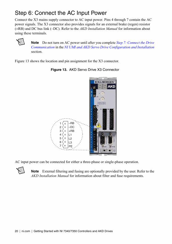
Step 6: Connect the AC Input PowerConnect the X3 mains supply connector to AC input power. Pins 4 through 7 contain the AC power signals. The X3 connector also provides signals for an external brake (regen) resistor (±RB) and DC bus link (–DC). Refer to the AKD Installation Manual for information about using these terminals.
Note Do not turn on AC power until after you complete Step 7: Connect the Drive Communication in the NI UMI and AKD Servo Drive Configuration and Installation section.
Figure 13 shows the location and pin assignment for the X3 connector.
Figure 13. AKD Servo Drive X3 Connector
AC input power can be connected for either a three-phase or single-phase operation.
Note External filtering and fusing are optionally provided by the user. Refer to the AKD Installation Manual for information about filter and fuse requirements.
1234567
–RB–DC+RBL1L2L3PE

Getting Started with NI 7340/7350 Controllers and AKD Drives | © National Instruments | 21
Figure 14 shows three-phase connection.
Figure 14. AC Input Power Three-Phase Connection
Figure 15 shows single-phase connection.
Figure 15. AC Input Power Single-Phase Connection
Step 7: Connect the Drive CommunicationComplete the following steps to set up the drive for software configuration using Ethernet. These steps assume you are connecting the AKD servo drive using a hub, switch, or router using DHCP. If you cannot use DHCP, refer to Connecting to the PC Using a Static IP in the Tips and Troubleshooting section for instructions about direct connection using a static IP address.
1. Set S1 and S2 on the drive to 0 to configure the drive for DHCP mode. The drive obtains an IP address from an external DHCP server if one exists on the network. If no DHCP server is present, the drive assumes an automatic private IP address in the form of 169.254.x.x. This process may take up to a minute to complete. Figure 9 shows the locations of S1 and S2.
2. Connect the AKD servo drive X11 service port to a hub, switch, or router using an Ethernet cable.
DC Out
L1
User-ProvidedFilter
(Optional)
L2
L3
AKD Servo Drive
ProtectiveEarth
L1
L2
L3
ProtectiveEarth
L1User-Provided
Filter(Optional)
L2
L3
L1
Neutral (L2)
ProtectiveEarth
ProtectiveEarth
DC Out
AKD Servo Drive

22 | ni.com | Getting Started with NI 7340/7350 Controllers and AKD Drives
Figure 16 shows the location of the X11 service port on the drive.
Figure 16. AKD Servo Drive X11 Connector
Step 8: Confirm Drive ConnectionsAfter all hardware connections have been made complete the following steps to confirm the AKD hardware setup.
1. Apply AC power.
2. Turn on the +24 V power supply. After logic power is supplied to the drive, the drive displays the following sequence of flashes in the LED indicators. Figure 9 shows the location of the LED indicators on the AKD servo drive.
a. – –
b. []
c. Drive IP address, flashed sequentially
d. Drive status, either current operation mode or the fault code if there is a fault condition. The operation modes are as follows:
• o0—torque mode (current mode)
• o1—velocity mode
• o2—position mode
Note If the drive shows a fault code, click the Clear Faults button on the AKD WorkBench software toolbar after you install the AKD WorkBench software in Step 3: Install AKD WorkBench and Configure the Drive in the Software Installation and Configuration section and connect to the drive to clear the fault state. If the fault
LED

Getting Started with NI 7340/7350 Controllers and AKD Drives | © National Instruments | 23
reappears, refer to the AKD Fault and Warning Messages Card that came with the drive for more information about the fault, including possible solutions. After resolving the cause of the fault, click the Clear Faults button on the toolbar again. Figure 19 shows the location of the Clear Faults toolbar button in the AKD WorkBench software.
Software Installation and ConfigurationThis section covers installing and configuring the software for the AKD servo drive and NI 7340/7350 motion controller.
Step 1: Update Firmware on the Motion ControllerFirmware is software that is loaded onto the motion controller. Firmware allows you to update the motion controller with new features and updates. The latest firmware is automatically installed on the computer when you install the latest version of NI-Motion. You must download the firmware to the motion controller.
Complete the following steps to download firmware to an NI motion controller:
1. Click the MAX icon on the desktop ( ), or select Start»All Programs»National Instruments»Measurement & Automation to open MAX.
2. Expand Devices and Interfaces, and then expand NI Motion Devices in the configuration tree.
3. Select the motion controller for which you want to download firmware. An exclamation point on the NI 7340/7350 motion controller icon ( ) indicates that the firmware is outdated and must be updated.
4. Click the Firmware tab at the bottom of the window. An exclamation point appears for each firmware sector that requires an update.
5. Click the Update Firmware button at the top of the window to update all the firmware files on your device.
Step 2: Configure the NI Motion ControllerComplete the following steps to configure the NI 7340/7350 motion controller for use with the AKD servo drive.
1. Open MAX, if it is not already open.
2. Expand Devices and Interfaces, expand NI Motion Devices, and then select the appropriate motion controller in the configuration tree.
3. Expand Default xxxx Settings, and then expand the axis associated with the AKD servo drive.
4. Click Axis Configuration and set Type to Servo.
5. Click Motion I/O Settings and select Disabled for the Forward Limit Switch, Reverse Limit Switch, and Home Switch.

24 | ni.com | Getting Started with NI 7340/7350 Controllers and AKD Drives
Note These configuration settings disable limits for initial setup and testing purposes. National Instruments recommends connecting and enabling limits in your final application.
6. Set the limit and home input active state. This prevents the limit active error from occurring when no limits are connected.
a. UMI-7764—Active Low Polarity
b. UMI-7772/74—Active High Polarity
7. Set Inhibit Output Settings to Active Low Polarity.
8. Click Control Loop Settings and make the following changes:
a. Set Kp to 50.
b. Set Kd to 300.
c. Set Ki to 0.
Note These values do not result in a properly tuned motor, but may allow you to perform a simple move for testing purposes. After connecting the other mechanical elements of the system, use the Servo Tune Main tab to tune the control loop settings and determine the relative stability of the servo axis. Refer to Manually Tuning a System From Scratch in the Measurement & Automation Explorer Help for Motion for information about using the Servo Tune tabs to tune your motor.
9. Click Encoder Settings.
a. In the Polarities section confirm that the Line State for A, B, and Index is set to Active High.
b. In the Index Reference Criteria section confirm that the Line State for A and B is set to Active.
c. Set Encoder counts per revolution to 8,000. This setting is the encoder resolution in quadrature counts per revolution and must correspond to the AKD WorkBench emulated encoder output Resolution setting in lines per revolution multiplied by four. You may want to choose a different resolution depending on your application needs.
Note You configure the emulated encoder output Resolution setting in Step 3: Install AKD WorkBench and Configure the Drive in the Software Installation and Configuration section.

Getting Started with NI 7340/7350 Controllers and AKD Drives | © National Instruments | 25
When you are finished the Encoder Settings page will look similar to Figure 17.
Figure 17. MAX Encoder Settings Page
10. Click Initialize on the toolbar to send the updated settings to the motion controller. Initializing the motion controller resets it to a known starting state so that it is ready for commands.
Step 3: Install AKD WorkBench and Configure the DriveAKD WorkBench is available on the CD that came with the AKD servo drive and is also available from ni.com/updates. Complete the following steps to install AKD WorkBench.
1. Insert the AKD WorkBench CD in the CD-ROM drive.
2. Double-click Full Setup.exe to launch the installer.
3. Follow the onscreen instructions to complete the installation.
Complete the following steps to configure the drive settings with AKD WorkBench.
1. Launch the AKD WorkBench software by clicking the AKD WorkBench icon on the desktop ( ), or by selecting Start»All Programs»Kollmorgen»AKD WorkBench.
2. Select the drive to configure from the list and click Connect.
Note If the drive is not in the list, refer to the Tips and Troubleshooting section of this document for possible solutions.

26 | ni.com | Getting Started with NI 7340/7350 Controllers and AKD Drives
Figure 18 shows the AKD WorkBench start page.
Figure 18. AKD WorkBench Start Page
1 Available Drives 2 Specify Address 3 Connect to Drive
1 32

Getting Started with NI 7340/7350 Controllers and AKD Drives | © National Instruments | 27
3. (Optional) Change the name of the drive from the default name of no_name on the AKD Overview page to a more descriptive name.
Figure 19 shows the AKD Overview page.
Figure 19. AKD WorkBench Overview Page
4. Configure the command source and operation mode.
a. Open the Settings page and set the Command Source to 3 - Analog.
b. Set the Operation Mode to 0 - Torque Mode.
1 Software Enable/Disable2 Command Source3 Operation Mode4 Clear Faults5 Save Configuration Settings to Drive
6 Software Enable/Disable7 Drive Active Indicator8 Software Enable Status Indicator9 Hardware Enable Status Indicator10 Fault Indicator
1 2 4 53
7 8 109
6

28 | ni.com | Getting Started with NI 7340/7350 Controllers and AKD Drives
When you have updated these settings the Settings page should look similar to the following figure.
Figure 20. AKD WorkBench Settings Page
5. Configure the emulated encoder output.
a. Expand the Settings tree item and open the Encoder Emulation page.
b. Select 1 - Output - With once per rev index pulse from the Function dropdown list.
c. Set the Resolution to 2,000 lines/rev.
Note The encoder resolution output value determines the equivalent resolution of an incremental encoder in pulses per revolution (PPR). A resolution of 2,000 lines/rev is the same as 8,000 quadrature counts per revolution. You may want to choose a different value depending on your application needs. In general, higher resolution values result in more difficult servo loop tuning; lower resolution values provide less accuracy. If you select a different value for Resolution, remember to update the Encoder counts per revolution setting in MAX.
d. Set the Index Offset to 0.
1 Command Source Setting 2 Operation Mode Setting
1 2

Getting Started with NI 7340/7350 Controllers and AKD Drives | © National Instruments | 29
Figure 21 shows the AKD WorkBench Encoder Emulation page.
Figure 21. AKD WorkBench Encoder Emulation Page
6. Configure the analog input command scaling.
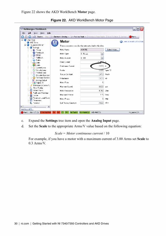
a. Expand the Settings tree item and open the Motor page.
b. Write down the motor Continuous Current value.
Note Motor continuous current is in Arms.
1 Function Setting 2 Resolution Setting
1 2
30 | ni.com | Getting Started with NI 7340/7350 Controllers and AKD Drives
Figure 22 shows the AKD WorkBench Motor page.
Figure 22. AKD WorkBench Motor Page
c. Expand the Settings tree item and open the Analog Input page.
d. Set the Scale to the appropriate Arms/V value based on the following equation:
Scale = Motor continuous current / 10
For example, if you have a motor with a maximum current of 3.00 Arms set Scale to 0.3 Arms/V.

Getting Started with NI 7340/7350 Controllers and AKD Drives | © National Instruments | 31
Figure 23 shows the analog input scaling setting.
Figure 23. AKD WorkBench Analog Input Scale Setting
7. Configure the software enable signal:
a. Click the Parameters tree icon to list all configurable drive parameters.
b. Expand the Drive section.
c. Set the Software enable default parameter to 1.

32 | ni.com | Getting Started with NI 7340/7350 Controllers and AKD Drives
Figure 24 shows the AKD WorkBench parameters page.
Figure 24. AKD WorkBench Parameters Page
Note If you are using an EtherCAT AKD drive in analog mode, refer to Using an EtherCAT AKD Drive in Analog Mode in the Tips and Troubleshooting section for additional settings you may need to apply.
8. Activate the software enable on the drive by clicking the Enable button on the AKD Overview page or on the toolbar. Figure 19 shows the location of the Enable button.
9. Save all configuration changes to the drive by clicking the Save to Drive toolbar button shown in Figure 19.

Getting Started with NI 7340/7350 Controllers and AKD Drives | © National Instruments | 33
Step 4: Test the Motor In MAXYou will now move the motor using the NI motion controller and MAX. Select the 1-D Interactive panel in the Configuration tree and change the settings to match those shown in Figure 25. Change the axis if you are not using Axis 1.
Figure 25. 1-D Interactive Panel Settings
10. Click Start. Your motor should rotate 25 times at 60 rpm.
11. Finalize your motion system setup by connecting and configuring additional I/O such as limits as required by your application.
• If using the UMI-7764, use the available screw-terminal connections on the same axis terminal block as the AKD servo drive connections.
• If using the UMI-7772/74, use the screw-terminal connections on the UMI-7772/74 to AKD drive cable. Table 1 shows the screw-terminal connector pinout.
12. Tune the motor with a load connected using the Servo Tune Main tab in MAX. Refer to Manually Tuning a System From Scratch topic in the Measurement & Automation Explorer Help for Motion for information about using the Servo Tune tabs to tune your motor.

34 | ni.com | Getting Started with NI 7340/7350 Controllers and AKD Drives
Tips and Troubleshooting
The Drive Does Not EnableIf, after going through all steps in this document, the AKD servo drive does not enable, verify the following settings:
• The Inhibit Output from the NI 7340/7350 must not be active. Figure 19 shows the location of the hardware enable indicator in the AKD WorkBench software.
• The software enable must be enabled. This setting is available on the upper toolbar in the AKD WorkBench software. Figure 19 shows the location of the software enable indicator and toolbar button.
• The drive must not be in a fault state. Click the Clear Faults button on the toolbar to clear the fault state after determining and fixing the source of the fault. Figure 19 shows the location of the Fault indicator and Clear Faults toolbar button.
Tip Refer to the AKD Fault and Warning Messages card that came with the drive for fault information and solutions.
Cannot Communicate With the Drive Using EthernetConfirm that the link LEDs on the drive and PC are both illuminated. Figure 16 shows the location of the link LED on the drive.
UMI-7772/74 Does Not Turn On Confirm that the V terminal is connected to the Viso terminal and the C terminal is connected to the Ciso terminal. Figure 5 shows the power terminal block.
Drive Does Not Turn OnConfirm that the +24 power supply is properly connected and that the STO input is powered by either +24 V or connected to an external safety relay. Refer to Step 4: Connect the Logic Power Supply to the AKD Servo Drive for more information.
Connecting to the PC Using a Static IP1. Use the S1 and S2 rotary switches on the drive to set a static IP address. The IP address is
192.168.0.S1S2. For example, if S1 is set to 2 and S2 is set to 3 the IP address is 192.168.0.23.
Note If you change S1 or S2 when the +24 V power supply is powered on, you must unplug the network cable from the drive for at least three seconds to reset the IP address.
2. Connect the AKD servo drive to the computer directly using an Ethernet cable. Figure 16 shows the location of the X11 service port on the drive.

Getting Started with NI 7340/7350 Controllers and AKD Drives | © National Instruments | 35
3. Complete the following steps to configure the static IP based on your operating system version.
(Windows XP)a. Select Start»Control Panel»Network Connections to open the Network
Connections dialog box.
b. Select the network connection type corresponding to the port you used to connect the AKD servo drive. This will most likely be Local Area Connection x, where x corresponds to the number of the connection.
c. Click Properties to open the Local Area Connection Properties dialog box.
d. Select Internet Protocol (TCP/IP) from the list and click Properties.
e. In the Internet Protocol (TCP/IP) dialog box, select Use the following IP address.
f. Change IP address to 198.168.0.100.
g. Change Subnet mask to 255.255.255.0.
(Windows Vista or Later)a. Select Start»Control Panel»Network and Sharing Center.
b. Select the network connection type corresponding to the port you used to connect the AKD servo drive. This will most likely be Local Area Connection x, where x corresponds to the number of the connection.
c. Click Properties to open the Local Area Connection Properties dialog box.
d. Select Internet Protocol Version 4 (TCP/IPv4) from the list and click Properties.
e. In the Internet Protocol Version 4 (TCP/IPv4) dialog box, select Use the following IP address.
f. Change IP address to 198.168.0.100.
g. Change Subnet mask to 255.255.255.0.
Verify that S1 and S2 are set to non-zero values.
The Motor Responds PoorlyUse the Servo Tune tabs in MAX to change the control loop settings for the motor. Refer to Manually Tuning a System From Scratch topic in the Measurement & Automation Explorer Help for Motion for information about using the Servo Tune tabs to tune your motor.
Using an EtherCAT AKD Drive in Analog ModeIf you are using an EtherCAT AKD drive in Analog mode with firmware version M_01-04-00-003 or later, you must set FBUS.PARAM05 to 4. Complete the following steps to set this parameter.
1. Click the Parameters tree icon to list all configurable drive parameters.
2. Expand the Fieldbuses section.
3. Set the FBUS.PARAM05 parameter to 4.
4. Save all configuration changes to the drive by clicking the Save to Drive toolbar button shown in Figure 19.

36 | ni.com | Getting Started with NI 7340/7350 Controllers and AKD Drives
Figure 26 shows the Fieldbuses section of the AKD WorkBench parameters page.
Figure 26. AKD WorkBench Fieldbuses Section
Cannot See the AKD Servo Drive in the AKD WorkBench SoftwareManually enter the drive IP address by enabling the Specify Address checkbox on the AKD WorkBench software Start Page shown in Figure 18. To obtain the drive IP address either press the B1 button on the top of the drive or disconnect and reconnect the Ethernet cable. In either case, the LED displays the digits and dots of the IP address in sequence. Figure 27 shows the location of the B1 button.
Figure 27. AKD Servo Drive B1 Button
X11
B1

Getting Started with NI 7340/7350 Controllers and AKD Drives | © National Instruments | 37
Wiring Diagram
Figure 28. AKD Wiring Diagram
M
Shield Connection Via Plug
X11
7
6
5
4
6
5
4
3
2
1
3
2
8
7
9
10
4
3
2
1
5
6
8
7
6
5
4
3
2
1
9
10
1
B–
B+
PE
U1
V1
W1
FB1
FB2
FN1 FN2 FN3 FH1 FH2 FH3
3
2
X8
X7X10
X2
X3
Analog–In +
Analog–Out +
DIGITAL–IN5(PSTOP)
DIGITAL–IN1
DIGITAL–IN7
DIGITAL–IN3
DIGITAL–IN4
DIGITAL–IN2
DIGITAL–OUT1+
DIGITAL–OUT2+
DIGITAL–OUT2–
DIGITAL–OUT1–
DIGITAL–IN6(NSTOP)
AGND
DGND
DGND
Fault
Feedback
Thermal ControlIncluded
Reference Safety Instructionsand Use As Directed
– Br
– RB
– DC
L1
L2
L3
PE
+ 24V
STO
GND
+ RB
+
(+ DC)
+ Br
PE
U
V
W
ENABLE
Analog–In –
+ Referred toI/O–GND
I/O–GND
EmergencyStop Circuit
Digital1
Digital2
+/– 10V SpeedSetpoint
+/– 10V
+ 24V Referredto I/O GND
+ 24V Referredto I/O GNDI/O–GND
Control
+
TachometerVoltage
+
–
–
Chassis Ground Connection (Panel)
PE–Connection (Protective Earth)
Feedback
RegenerationResistor
Filter Supply Unit24V DC
L1 L2 L3 PE
MainsContactor
+ –
X9Encoder
Emulation
9 EncoderEvaluation
X11
TCP/IP
Service8

38 | ni.com | Getting Started with NI 7340/7350 Controllers and AKD Drives
Worldwide Support and ServicesThe National Instruments Web site is your complete resource for technical support. At ni.com/support you have access to everything from troubleshooting and application development self-help resources to email and phone assistance from NI Application Engineers.
Visit ni.com/services for NI Factory Installation Services, repairs, extended warranty, calibration, and other services.
Visit ni.com/register to register your National Instruments product. Product registration facilitates technical support and ensures that you receive important information updates from NI.
A Declaration of Conformity (DoC) is our claim of compliance with the Council of the European Communities using the manufacturer’s declaration of conformity. This system affords the user protection for electromagnetic compatibility (EMC) and product safety. You can obtain the DoC for your product by visiting ni.com/certification. If your product supports calibration, you can obtain the calibration certificate for your product at ni.com/calibration.
National Instruments corporate headquarters is located at 11500 North Mopac Expressway, Austin, Texas, 78759-3504. National Instruments also has offices located around the world to help address your support needs. For telephone support in the United States, create your service request at ni.com/support and follow the calling instructions or dial 512 795 8248. For telephone support outside the United States, visit the Worldwide Offices section of ni.com/niglobal to access the branch office Web sites, which provide up-to-date contact information, support phone numbers, email addresses, and current events.

© 2010–2012 National Instruments. All rights reserved. Printed in Hungary.
325543C-01 Sep12 *325543C-01*
CVI, LabVIEW, National Instruments, NI, ni.com, the National Instruments corporate logo, and the Eagle logo are trademarks of National Instruments Corporation. Refer to the Trademark Information at ni.com/trademarks for other National Instruments trademarks. The mark LabWindows is used under a license from Microsoft Corporation. Windows is a registered trademark of Microsoft Corporation in the United States and other countries. Other product and company names mentioned herein are trademarks or trade names of their respective companies. For patents covering National Instruments products/technology, refer to the appropriate location: Help»Patents in your software, the patents.txt file on your media, or the National Instruments Patents Notice at ni.com/patents. You can find information about end-user license agreements (EULAs) and third-party legal notices in the NI-Motion Readme. Refer to the Export Compliance Information at ni.com/legal/export-compliance for the National Instruments global trade compliance policy and how to obtain relevant HTS codes, ECCNs, and other import/export data.