getting the most out of your osa (open systems adapter ... · getting the most out of your osa...
TRANSCRIPT

Getting the most out of your OSA(Open Systems Adapter) with z/OSComm Server
David Herr – [email protected]
IBM Raleigh, NC
Friday, February 16th, 8:00am
Session: 12862

Trademarks, notices, and disclaimers
• Advanced Peer-to-PeerNetworking®
• AIX®• alphaWorks®• AnyNet®• AS/400®• BladeCenter®• Candle®• CICS®• DataPower®• DB2 Connect• DB2®• DRDA®• e-business on demand®• e-business (logo)• e business(logo)®• ESCON®• FICON®
• GDDM®• GDPS®• Geographically Dispersed
Parallel Sysplex• HiperSockets• HPR Channel Connectivity• HyperSwap• i5/OS (logo)• i5/OS®• IBM eServer• IBM (logo)®• IBM®• IBM zEnterprise™ System• IMS• InfiniBand ®• IP PrintWay• IPDS• iSeries• LANDP®
• Language Environment®• MQSeries®• MVS• NetView®• OMEGAMON®• Open Power• OpenPower• Operating System/2®• Operating System/400®• OS/2®• OS/390®• OS/400®• Parallel Sysplex®• POWER®• POWER7®• PowerVM• PR/SM• pSeries®• RACF®
• Rational Suite®• Rational®• Redbooks• Redbooks (logo)• Sysplex Timer®• System i5• System p5• System x®• System z®• System z9®• System z10• Tivoli (logo)®• Tivoli®• VTAM®• WebSphere®• xSeries®• z9®• z10 BC• z10 EC
• zEnterprise• zSeries®• z/Architecture• z/OS®• z/VM®• z/VSE
The following terms are trademarks or registered trademarks of International Business Machines Corporation in the United States or other countries or both:• Adobe, the Adobe logo, PostScript, and the PostScript logo are either registered trademarks or trademarks of Adobe Systems Incorporated in the United States, and/or other countries.• Cell Broadband Engine is a trademark of Sony Computer Entertainment, Inc. in the United States, other countries, or both and is used under license there from.• Java and all Java-based trademarks are trademarks of Sun Microsystems, Inc. in the United States, other countries, or both.• Microsoft, Windows, Windows NT, and the Windows logo are trademarks of Microsoft Corporation in the United States, other countries, or both.• InfiniBand is a trademark and service mark of the InfiniBand Trade Association.• Intel, Intel logo, Intel Inside, Intel Inside logo, Intel Centrino, Intel Centrino logo, Celeron, Intel Xeon, Intel SpeedStep, Itanium, and Pentium are trademarks or registered trademarks of Intel
Corporation or its subsidiaries in the United States and other countries.• UNIX is a registered trademark of The Open Group in the United States and other countries.• Linux is a registered trademark of Linus Torvalds in the United States, other countries, or both.• ITIL is a registered trademark, and a registered community trademark of the Office of Government Commerce, and is registered in the U.S. Patent and Trademark Office.• IT Infrastructure Library is a registered trademark of the Central Computer and Telecommunications Agency, which is now part of the Office of Government Commerce.Notes:
• Performance is in Internal Throughput Rate (ITR) ratio based on measurements and projections using standard IBM benchmarks in a controlled environment. The actual throughput that anyuser will experience will vary depending upon considerations such as the amount of multiprogramming in the user's job stream, the I/O configuration, the storage configuration, and the workloadprocessed. Therefore, no assurance can be given that an individual user will achieve throughput improvements equivalent to the performance ratios stated here.
• IBM hardware products are manufactured from new parts, or new and serviceable used parts. Regardless, our warranty terms apply.
• All customer examples cited or described in this presentation are presented as illustrations of the manner in which some customers have used IBM products and the results they may haveachieved. Actual environmental costs and performance characteristics will vary depending on individual customer configurations and conditions.
• This publication was produced in the United States. IBM may not offer the products, services or features discussed in this document in other countries, and the information may be subject tochange without notice. Consult your local IBM business contact for information on the product or services available in your area.
• All statements regarding IBM's future direction and intent are subject to change or withdrawal without notice, and represent goals and objectives only.
• Information about non-IBM products is obtained from the manufacturers of those products or their published announcements. IBM has not tested those products and cannot confirm theperformance, compatibility, or any other claims related to non-IBM products. Questions on the capabilities of non-IBM products should be addressed to the suppliers of those products.
• Prices subject to change without notice. Contact your IBM representative or Business Partner for the most current pricing in your geography.
Refer to www.ibm.com/legal/us for further legal information.
The following terms are trademarks or registered trademarks of International Business Machines Corporation in the United States or other countries or both:
* All other products may betrademarks or registeredtrademarks of theirrespective companies.
© 2013 SHARE and IBM Corporation

Agenda
Disclaimer: All statements regarding IBM future direction or intent, including current product plans, are subject tochange or withdrawal without notice and represent goals and objectives only. All information is provided forinformational purposes only, on an “as is” basis, without warranty of any kind.
What is QDIO?
OSA inbound “routing”
Overview of selected recent OSAenhancements
Appendix
© 2013 SHARE and IBM Corporation

What is QDIO?

Queued Direct IO (QDIO) – How System z accesses a LAN
ControlUnit
NIC
Channel
HostMemory
Channel-attacheddevice
NIC
HostMemory
Store and forward
NIC
HostMemory
Datarouter
OSE: LCS or LSAOSA
OSD: QDIOOSA-Express(2)
OSD: QDIOOSA-
Express3/4S
OSA
OSA OSA
OSA-Express3/4S usesdirect memory access(DMA) technologies andhardware data router –allowing data to flowthrough OSA withoutslow store and forwardprocessing.
The OSA adapter andSystem z can accessshared memory. OSAinterrupts System z usingPCI, while System z“interrupts” OSA viaSignaling (SIGAinstruction)
The same way a mainframeconnected to an old IBM3172, or a Cisco CIP
© 2013 SHARE and IBM Corporation

OSA and QDIO work together
QDIO Layer 3 (z/OS)– for TCP/IP traffic only (IPv4 and IPv6)– z/OS, z/VM, z/VSE, z/TPF, and Linux on System z– OSA IP Processing Assist (IPA) offloads many TCP/IP functions
to the OSA adapter, of which some are:– Performs all ARP processing (IPv4 only)– Provides Multicast support– Builds MAC and LLC headers– Performs checksum processing– Performs outbound TCP segmentation
– For SNA/APPN/HPR traffic with QDIO layer 3: use TN3270 andEnterprise Extender
QDIO Layer 2 – network protocol agnostic– z/VM V5.2 with PTFs and Linux on System z
– z/OS does not support QDIO Layer 2– Network protocol may be TCP/IP, SNA LLC2, NetBIOS, etc. (no IP Assist)– Linux uses QDIO Layer 2 for SNA LLC2 traffic in/out of Linux
– IBM Communications Server for Linux and Communications Controller for Linux OSA and QDIO are designed for high speed communication between System z and the Local Area
Network– Reduced TCP/IP path length– QDIO IP Processing Assist– LPAR-to-LPAR communication with port sharing– Direct Memory Access (DMA) Protocol
– Memory-to-memory communication– I/O interrupts minimized– Continuous direct data exchanges
– Dynamic customization 10 Gigabit Ethernet, Gigabit Ethernet, 1000BASE-T Ethernet (1000, 100, and 10 Mbit)
NIC
HostMemory
Datarouter
OSA
© 2013 SHARE and IBM Corporation

A little more on QDIO and devices
Control data between z/OS CS and the OSA port is exchanged over one readdevice and one write device (READ even address, WRITE odd address)
– The READ and WRITE device pair is shared among all the IP interface definitions in anLPAR that use the same OSA port
Data is exchanged over data devices One data device is used per:
– A set of exactly one IPv4 and one IPv6 interface– IPv4: DEVICE+LINK, IPv6: INTERFACE
– One IPv4 interface defined with INTERFACE– One IPv6 interface
One data device is used by OSAENTA trace,if that trace is activated
VTAM/DLC
TCP/IP DEVICE+LINK 1 IPv4TCP/IP INTERFACE 2 IPv6
TCP/IP INTERFACE 3 IPv4
TCP/IP INTERFACE 4 IPv6
OSA Port
WRITE Control
READ Control
Data dev 1
Data dev 2
Data dev 3
LNCTL=MPC,READ=(2FD6),WRITE=(2FD7),MPCLEVEL=QDIO,DATAPATH=(2FD8,2FD9,2FDA,2FDB),PORTNAME=(O3ETHB1P),PORTNUM=(1)
TCPIP1
TCPIP2
TRLE
© 2013 SHARE and IBM Corporation

OSA inbound “routing”

• Frame CheckSequence (FCS)
• Dest MAC addr• Src MAC addr• Next header
• VLAN ID• VLAN priority• Payload protocol
• Dest IP addr• Src IP addr• Type Of Service• Transport protocol
• Dest port number• Src port number
Some basic LAN technology overview
The LAN infrastructure transports “Frames” between Network Interface Cards (NICs)that are attached to the LAN media (Copper or fiber optic)
– Ethernet II (DIX) – MTU 1500 and jumbo frame MTU 9000 (most common)
Each NIC has a physical hardware address– A Media Access Control (MAC) address
– Burned in (world-wide unique by vendors) or alternatively locally administered
Every frame comes from a MAC and goes to a MAC– There are special MAC values for broadcast and multicast frames
Every frame belongs to the physical LAN or to one of multiple Virtual LANs (VLAN) onthe physical LAN
– A VLAN ID is in the IEEE801.Q header if VLAN technologies are in use
A frame carries a payload of a specified protocol type, such as ARP, IPv4, IPv6, SNALLC2, etc.
Ethernet II Hdr IEEE801.Q Hdr IP Hdr. TCP Hdr. Data Trailer
Ethernet II (DIX) LAN Frame
IP PacketTCP Segmentoptional
© 2013 SHARE and IBM Corporation

IP address MAC
10.1.1.2 MAC2
3.
1.
2.
Correlation of IPv4 addresses and MAC addresses on a LAN –Address Resolution Protocol (ARP)
An IPv4 node uses the ARP protocol to discover the MAC address of anotherIPv4 address that belongs to the same IPv4 subnet as it does itself.
ARP requests are broadcasted to all NICs on the LAN The one NIC that has a TCP/IP stack with the requested IPv4 address responds
directly back to the IPv4 node that sent out the broadcast Each IPv4 node maintains a cache of IPv4 addresses and associated MAC
addresses on their directly connected LANs
TCP/IP10.1.1.1
MAC1
MAC2
MAC3
TCP/IP10.1.1.3
TCP/IP10.1.1.2
IP address MAC
10.1.1.2 MAC2
10.1.1.3 MAC3
ARP Cache
Who ownsIPv4 address10.1.1.3 ??
I do and myMAC addressis MAC3 !!
Here is a unicastpacket for10.1.1.3 at MAC3
OSANIC
OSANIC
NIC
IPv6 uses a similarmethod, but based onuse of multicast. TheIPv6 protocol is knownas ND for NeighborDiscovery.
© 2013 SHARE and IBM Corporation

An example – formatted by Wireshark(http://www.wireshark.org)
A sample Address Resolution Request frame
© 2013 SHARE and IBM Corporation

So how does this work in a System z environment with shared(virtualized) OSA adapters?
An OSA NIC has a physical MACaddress, just like all NICs
An OSA NIC is often used by multipleLPARs and TCP/IP stacks– The NIC is virtualized so it functions as
the NIC for multiple TCP/IP stacks,each with their own IP address
If someone ARPs for 10.0.1.1 inLPAR1, OSA will return MAC1
If someone ARPs for 10.0.1.2 inLPAR2, OSA will also return MAC1
So what does OSA then do when aunicast frame arrives with adestination MAC address of MAC1?– It peeks into the IP header inside the
frame, and consults a table known asthe OSA Address Table (OAT) to seewhich LPAR the IP address inside theframe belongs to
IP address LPAR / Device
192.168.1.1 LPAR1/Dx
192.168.2.1 LPAR2/Dy
10.0.1.1 LPAR1/Dx
10.0.1.2 LPAR2/Dy
Primary LPAR2/Dy
Secondary LPAR1/Dx
LPAR1VIPA 192.168.1.1
OSA 10.0.1.1
LPAR2VIPA 192.168.2.1
OSA 10.0.1.2
EMIF(PR/SM)
OSA
10.0.1.010.0.1.0
10.0.3.010.0.3.0
10.0.4.010.0.4.0
Physical MAC: MAC1
OSADefaultRouter
OSA AddressTable (OAT)
Dest_MAC Dest_IPv4 Who gets it? Why?
MAC1 10.0.1.1 LPAR1 Registered
MAC1 192.168.1.1 LPAR1 Registered
MAC1 10.0.1.2 LPAR2 Registered
MAC1 192.168.2.1 LPAR2 Registered
MAC1 10.0.3.5 LPAR2 Default router
MAC1 10.0.4.6 LPAR2 Default router
If the destination IP address in aframe that arrives at the OSAadapter doesn't belong to any of theLPARs that share the adapter, thatIP packet is given to the LPAR thatacts as the Default OSA router.There are separate IPv4 and IPv6default OSA router specifications.
LAN frames
© 2013 SHARE and IBM Corporation

Setting a few facts straight about OSA and “routing”
OSA is not a full-function IP router.– OSA can analyze a destination IP address in a LAN frame to decide which LPAR an
incoming IP packet belongs to.– OSA does not participate in dynamic routing updates.– OSA does not act as a general IP router
– Depends on the TCP/IP stacks to do that and handle all IP routing issues.
By default, the OSA NIC has a single physical MAC address that is shared among allthe LPARs that share the OSA port.– All IP packets to all LPARs can be destined for one and the same MAC address– In that case, OSA selects correct stack based on destination IP address and the OSA
Address Table
If z/OS acts as an IP router to IP networks behind z/OS, the destination address maybe any IP address on those networks behind z/OS.– LPAR designated as default router will receive such packets– Can become extremely cumbersome to set up if LPARs that share an OSA port are
connected to different back-end networks
When a port is defined as an OSE/LCS port, the content of the OAT must bemaintained manually through OSA/SF interaction.
When a port is defined as a OSD/QDIO port, the content of the OAT is maintainedautomatically by the sharing TCP/IP stacks.
© 2013 SHARE and IBM Corporation

QDIO layer-3: less administration, more dynamics – but OATremains an important element of OSA inbound routing
LPAR1VIPA 192.168.1.1
OSA 10.0.1.1 Primary
LPAR2VIPA 192.168.2.1
OSA 10.0.1.2 Secondary
EMIF(PR/SM)
OSA
10.0.1.010.0.1.0
Physical MAC: MAC1
OSA AddressTable (OAT)
SetIP
SetPrimary
QDIO Layer 3 - the OSAadapter is IP-aware andoffloads certainfunctions from theTCP/IP stacks – check-summing, ARPprocessing, TCPsegmentation, etc.
QDIO device definitions in the TCP/IP stacks are used to dynamically establish the stack as the OATdefault router, secondary router, or non-router.
Whenever a QDIO device is activated or the TCP/IP home list is modified (through OBEYFILE commandprocessing or through dynamic changes, such as dynamic VIPA takeover), the TCP/IP stack updates theOAT configuration dynamically with the HOME list IP addresses of the stack.
The OAT includes all (non-LOOPBACK) HOME IP addresses of all the stacks that share the OSAadapter.
The fact that the OSA microcode is IP address-aware (as it is in this scenario) is the reason for referringto this as QDIO layer 3 processing (layer 3 is generally the networking layer in an OSI model - the IPnetworking layer when using TCP/IP)
IP address LPAR / Device
192.168.1.1 LPAR1/Dx
192.168.2.1 LPAR2/Dy
10.0.1.1 LPAR1/Dx
10.0.1.2 LPAR2/Dy
Primary LPAR1/Dx
Secondary LPAR2/Dy
OAT is maintaineddynamically by TCP/IP
OAT Updates:– LCS: operator intervention via OSA/SF commands– QDIO: dynamic by software via QDIO control channel
© 2013 SHARE and IBM Corporation
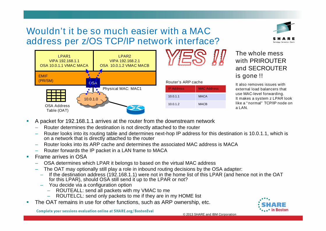
Wouldn’t it be so much easier with a MACaddress per z/OS TCP/IP network interface?
A packet for 192.168.1.1 arrives at the router from the downstream network– Router determines the destination is not directly attached to the router– Router looks into its routing table and determines next-hop IP address for this destination is 10.0.1.1, which is
on a network that is directly attached to the router– Router looks into its ARP cache and determines the associated MAC address is MACA– Router forwards the IP packet in a LAN frame to MACA
Frame arrives in OSA– OSA determines which LPAR it belongs to based on the virtual MAC address– The OAT may optionally still play a role in inbound routing decisions by the OSA adapter:
– If the destination address (192.168.1.1) were not in the home list of this LPAR (and hence not in the OATfor this LPAR), should OSA still send it up to the LPAR or not?
– You decide via a configuration option– ROUTEALL: send all packets with my VMAC to me– ROUTELCL: send only packets to me if they are in my HOME list
The OAT remains in use for other functions, such as ARP ownership, etc.
LPAR1VIPA 192.168.1.1
OSA 10.0.1.1 VMAC MACA
LPAR2VIPA 192.168.2.1
OSA 10.0.1.2 VMAC MACB
EMIF(PR/SM)
OSA
10.0.1.010.0.1.0
Physical MAC: MAC1
OSA AddressTable (OAT)
IP Address MAC Address
10.0.1.1 MACA
10.0.1.2 MACB
Router’s ARP cache
The whole messwith PRIROUTERand SECROUTERis gone !!
It also removes issues withexternal load balancers thatuse MAC-level forwarding.It makes a system z LPAR looklike a “normal” TCP/IP node ona LAN.
© 2013 SHARE and IBM Corporation

OSA-Express virtual MAC while operating in QDIO layer-3mode OSA MAC sharing problems do not exist if each stack has its own MAC
– A "virtual" MAC
– To the network, each stack appears to have a dedicated OSA port (NIC)
MAC address selection
– Coded in the TCP/IP profile
– Generated and assigned by the OSA adapter
All IP addresses for a stack are advertised with the virtual MAC
– by OSA using ARP for IPv4
– by the stack using ND for IPv6
All external routers now forward frames to the virtual MAC
– OSA will “route” to an LPAR/Stack by virtual MAC instead of IP address
– All stacks can be "routing" stacks instead of 1 PRIROUTER stack
Simplifies configuration greatly
– No PRIROUTER/SECROUTER!
Supported on System z10, z196, and EC12
No reasons not touse VMACs. Use
them!!!
© 2013 SHARE and IBM Corporation

What is a Virtual LAN (a VLAN)?
Wikipedia:
A virtual LAN, commonly known as a VLAN, is a group of hosts with acommon set of requirements that communicate as if they were attached to thesame broadcast domain, regardless of their physical location.
A VLAN has the same attributes as a physical LAN, but it allows for end stationsto be grouped together even if they are not located on the same network switch.
Network reconfiguration can be done through software instead of physicallyrelocating devices.
zOS-A zOS-B
OSA
zOS-C
OSA
VLAN 1 – IP Subnet10.0.1.0/24
VLAN 2 – IP Subnet10.0.2.0/24
L2TP may beused over longer
distancesLayer-2switch
Layer-2switch
Layer-2switch
Router Router
Hosts
Networkhardware
© 2013 SHARE and IBM Corporation

z/OS and VLANs
Depending on switch configuration, the switchmay interconnect the VLANs using a layer-3 IProuter function.
The subnets may belong to different routingdomains or OSPF areas:– Test, production, demo
The subnets may belong to different securityzones:– Intranet, DMZ
LPAR1VLAN ID 2
LPAR2VLAN ID 3
LPAR3VLAN ID 3
LPAR4VLAN ID 4
OSA
Trunk mode
Access modeVLAN ID 2
Access modeVLAN ID 3
Access modeVLAN ID 4
Switch
One OSA port, one fiber/cable,three LANs (three subnets)
Trunk connection for VLAN ID 2,VLAN ID 3, and VLAN ID 4
VLANID 2
VLANID 2
VLANID 3
VLANID 3
VLANID 4
VLANID 4
LPAR1 LPAR2 LPAR3 LPAR4
Physical network diagram Logical network diagram
Each frame on the trunk mode connectioncarries a VLAN ID in the IEEE802.3 headerthat allows the network equipment toclearly identify which virtual LAN eachframe belongs to.
On an access mode connection, theswitch will transport frames belonging tothe configured VLAN ID for that accessmode connection only.
VLAN is a LAN media virtualization technology that allowsmultiple independent IP networks (IP subnets) to shareone physical media, such as a cable, an adapter, or alayer-2 switch. Connectivity between VLANs is under
control of IP routers.
© 2013 SHARE and IBM Corporation

Multiple network interfaces (VLANs) per OSA port perstack per IP protocol version As installations consolidate multiple OSA Gigabit Ethernet ports to a smaller
number of 10 Gigabit Ethernet ports, low limits on VLANs has become toorestrictive:
– Not possible to retain existing network interface and IP subnet topology– Consolidating multiple LANs to one LAN requires IP renumbering
z/OS V1R10 added support for eight VLANs per IP protocol per OSA port:– Each VLAN on the same OSA port must use unique, non-overlapping IP
subnets or prefixes– Will be enforced by the TCP/IP stack
– Each VLAN must be defined using the INTERFACE configuration statement– IPv4 INTERFACE statement only supports QDIO interfaces
– Each VLAN must use layer-3 virtual MAC addresses with ROUTEALL, andeach VLAN must have a unique MAC address
z/OS V1R13 raised the number of VLANs to 32 per IP protocol per OSA port
DEV1LINK110.1.1.0/24
DEV1LINK110.1.2.0/24
DEV1LINK110.1.3.0/24
OSA1 GbE
OSA1 GbE
OSA1 GbE
INTERFACE1VLAN1VMAC110.1.1.0/24
OSA10 GbE
INTERFACE2VLAN2VMAC210.1.2.0/24
INTERFACE3VLAN3VMAC310.1.3.0/24
LAN1 LAN2 LAN3 VLAN1+VLAN2+VLAN3
Consolidatemultiple low-capacity LAN
interfaces to fewerhigh-capacity LANinterfaces withoutnetwork topology
impact.
© 2013 SHARE and IBM Corporation

A few more words on VLANs with z/OS CS
z/OS Communications Server supports one VLAN ID per defined network interface
– This is known as a global VLAN ID– Remember: z/OS CS now supports up to 32 interfaces per OSA port – each with its own
VLAN ID
– OSA performs inbound routing based on VLAN IDs in the incoming frames and only sendsframes to z/OS with the global VLAN ID z/OS has registered
Linux on System z supports multiple VLAN IDs per interface
– OSA sends multiple VLAN IDs up to Linux and Linux then de-multiplexes the different virtualLANs
Some interfaces that share an OSA port may select to not specify a VLAN ID, while othersdo specify a VLAN ID (a mixed VLAN environment)
– Warning: be very careful - mixed VLAN environments are not recommended due tocomplexities with OSA default router selection and other functional issues. Use VLAN IDs onall TCP/IP interfaces that share an OSA port - or not at all.
LPAR1No VLANNo VMAC
PRIROUTER
LPAR2VLAN ID 2No VMAC
PRIROUTER
LPAR3VLAN ID 2No VMAC
SECROUTER
LPAR4VLAN ID 3No VMAC
PRIROUTER
OSA
• LPAR1 acts as PriRouter for:• Untagged frames• Frames tagged with a null VLAN ID• Frames tagged with an unregistered (anything but VLAN 2 or
3) VLAN ID• Frames tagged with a registered VLAN ID, an unknown
destination IP address but no VLAN Pri/SecRrouter• LPAR2 acts as PriRouter for frames tagged with VLAN 2 while LPAR3
acts as SecRouter for that same VLAN.• LPAR4 acts as PriRouter for frames tagged with VLAN 3
Mixed VLAN environment without VMAC
Try to avoid this!
© 2013 SHARE and IBM Corporation

OSA inbound routing as of late 2012
Dest MAC– VMACs are unique
across all interfacesand VLANs that sharean OSA port
– z/OS CS registers VMACwith the OSA port
VLAN ID– If z/OS CS has set a global
VLAN ID for an interface,OSA verifies the frameVLAN ID matches theglobal VLAN ID
Dest IP address– Without VMAC, the OAT is
always used– With VMAC, the OAT is used if
ROUTELCL is specified Default OSA router
– If OAT is used and dest IPaddress is not in OAT, theinterface currently registeredas default router is selected
VLAN ID inFrame?
Yes No
Give it to selectedNetwork interface
AnyVLAN IDMatch?
Any VMACMatch?
Yes, continue withmatching subset ofnetwork interfaces
ROUTEALL?
Yes, continue withthe one matchingnetwork interface
Dest IPMatch in
OAT?
Yes
Any activedefault OSA
router?
No
No
Yes
YesYes
No
No
This is correct if all interfacesthat share the OSA port useVLAN IDs or none of them do. Ifsome do and others do not, thisbecomes utterly complex, ratherugly, and somewhat scary !!!!
Dest IPMatch in
OAT?
No
No
Dropit
Start
© 2013 SHARE and IBM Corporation

This elusive Maximum Transmission Unit – what is thesize really? Interface MTU
– Configured on the INTERFACE statement or learnedfrom the device
– For IPv4, OSA reports 1492/8992 – even whenyou use Ethernet II frames
– For IPv6, OSA reports 1500/9000 – because IPv6always uses Ethernet II frames
– Reported as ActMtu: in a DEVLINKS netstat report Configured route MTU
– For static routes: the value coded in the BEGINROUTESsection for the destination
– For dynamic routes: the MTU value from theOMPROUTE interface over which the route was learned
– If no MTU size defined in OMPROUTE, a default of 576will be used for IPv4
Actual route MTU– Minimum of the interface MTU and the configured route
MTU– If path MTU is not enabled, this is the MTU that will be
used for that route Path MTU
– With path MTU enabled, TCP/IP starts out trying to usethe actual route MTU and may then lower the MTU towhat is discovered
– With path MTU enabled, all frames are sent withthe Do Not Fragment bit
– Path MTU values are cached, but will timeoutafter a certain amount of time to accommodatetopology changes that allows a higher MTU
OSA
MTU: 1500
MTU: 896
MTU: 1500
Gigabit Ethernet MTUcapability 8992
INTERFACE .. MTU 8992
PROFILE
OSPF_Interface .. MTU 1500
OMPROUTE
MTU type MTU value
Interface MTU 8992
Configured route MTU 1500
Actual route MTU 1500
Path MTU to this destination 896
IPv6 alwaysuses pathMTU.
© 2013 SHARE and IBM Corporation

Some examples on MTU specifications
MTU 1500 configured on an IPv4 INTERFACE stmt:
– CfgMtu: 1500 ActMtu: 1500
– OSA reports 8992 in this case, but our configured MTU overrides that and determinesthe actual MTU
No MTU configured on an IPv4 INTERFACE stmt:
– CfgMtu: None ActMtu: 8992
– We have no configured MTU to override what OSA reports, so the actual MTU endsup being 8992 as reported by OSA for an IPv4 interface
No MTU configured on an IPv6 INTERFACE stmt:
– CfgMtu: None ActMtu: 9000
– Since this is an IPv6 interface, OSA reports the full jumbo frame size of 9000 bytes asthe MTU it supports. Since we did not override that with a configured MTU, the 9000ends up being the actual MTU size.
In the sample setup, an MTU of 1500 is coded in the OMPROUTE configuration file, so allactual route MTUs end up being 1500
– Default 9.42.105.65 UGO 0000000002 QDIO4A
– Metric: 00000001 MTU: 1500
© 2013 SHARE and IBM Corporation

Overview of selected recent OSAenhancements

Inbound OSA/QDIO performance: Dynamic LANidle timer Dynamic LAN idle timer is designed to reduce latency and improve network performance by
dynamically adjusting the inbound blocking algorithm.– When enabled, the z/OS TCP/IP Stack is designed to adjust the inbound blocking algorithm to best
match the application requirements.
For latency sensitive applications, the blocking algorithm is modified to be "latency sensitive." Forstreaming (throughput sensitive) applications, the blocking algorithm is adjusted to maximizethroughput. In all cases, the z/OS TCP/IP stack dynamically detects the application requirements,making the necessary adjustments to the blocking algorithm.
– The monitoring of the application and the blocking algorithm adjustments are made in real-time,dynamically adjusting the application's LAN performance.
System administrators can authorize the z/OS TCP/IP stack to enable a dynamic setting, whichwas previously a static setting.
– The z/OS TCP/IP stack is designed to dynamically determine the best setting for the current runningapplication based on system configuration, inbound workload volume, CPU utilization, and trafficpatterns.
For an OSA Express port in OSD/QDIO mode the z/OS TCP/IP profile INBPERF parameter canbe specified with one of the following options:
– MINCPU - a static interrupt-timing value, selected to minimize host interrupts without regard tothroughput
– MINLATENCY - a static interrupt-timing value, selected to minimize latency
– BALANCED (default) - a static interrupt-timing value, selected to achieve reasonably high throughputand reasonably low CPU
– DYNAMIC - implements the new dynamic LAN idle algorithm recommended!
© 2013 SHARE and IBM Corporation

Dynamic LAN Idle Timer: Performance Data
Dynamic LAN Idle improved RR1 TPS 50% and RR10 TPS by 88%. Response Time forthese workloads is improved 33% and 47%, respectively.
1h/8h indicates 100 bytes in and 800 bytes out
z10 (4 CP LPARs),z/OS V1R13, OSA-E31Gbe
-60-40
-200
20
4060
80
100
Dy
na
mic
LA
NId
lev
s.
Ba
lan
ce
d
RR1(1h/8h) RR10(1h/8h)
RR1 and RR10 Dynamic LAN Idle
Trans/Sec
Resp Time
© 2013 SHARE and IBM Corporation
Note: The performance measurements discussed in this presentation are z/OS V1R13 Communications Server numbers and were collected using adedicated system environment. The results obtained in other configurations or operating system environments may vary.

OSA-Express Network Traffic Analyzer (OSAENTA) function
Diagnosing OSA-Express QDIOproblems can be somewhat difficult
– TCP/IP stack (CTRACE and/orpacket trace)
– VTAM (VIT)
– OSA (hardware trace)
– Network (sniffer trace)
Often not clear where the problem is andwhich trace(s) to collect
– Offloaded functions and shared OSAscan complicate the diagnosis
– ARP frames– Segmentation offload
Supported with OSA-2, OSA-3, and OSA-4
Allows z/OS Communications Server to collect Ethernet data frames from the OSA adapter– Not a sniffer trace (but similar in some aspects)
– No promiscuous mode
– Minimizes the need to collect and coordinate multiple traces for diagnosis
– Minimizes the need for traces from the OSA Hardware Management Console (HMC)
– Formatted with the standard z/OS CS packet trace formatter– Including the ability to convert to Sniffer/Wireshark format
z/VM, Linux,z/VSE, z/TPF
z/OS
VTAM
TCPIPA TCPIPB TCPIPC TCPIPD
OSA-E2
Sniffer
Router/Switch
LAN
HMC Hardware
Trace
VIT
CTRACE
Packet Trace
Which trace
should I use?
© 2013 SHARE and IBM Corporation
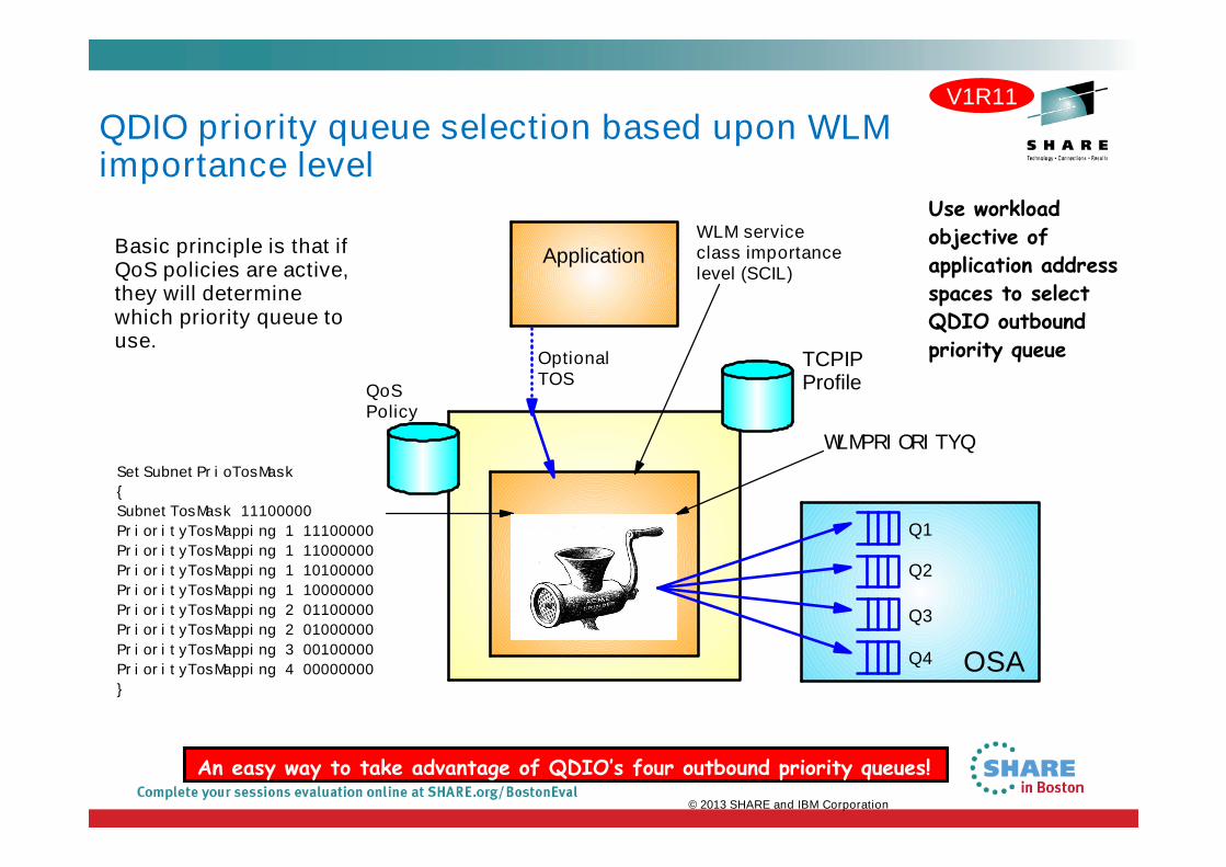
QDIO priority queue selection based upon WLMimportance level
QoSPolicy
Application
SetSubnetPrioTosMask
{
SubnetTosMask 11100000
PriorityTosMapping 1 11100000
PriorityTosMapping 1 11000000
PriorityTosMapping 1 10100000
PriorityTosMapping 1 10000000
PriorityTosMapping 2 01100000
PriorityTosMapping 2 01000000
PriorityTosMapping 3 00100000
PriorityTosMapping 4 00000000
}
WLM serviceclass importancelevel (SCIL)
TCPIPProfile
WLMPRIORITYQ
OptionalTOS
Basic principle is that ifQoS policies are active,they will determinewhich priority queue touse.
Use workload
objective of
application address
spaces to select
QDIO outbound
priority queue
Q1
Q2
OSA
Q3
Q4
V1R11
An easy way to take advantage of QDIO’s four outbound priority queues!
© 2013 SHARE and IBM Corporation

OSA Express (QDIO) WLM Outbound PriorityQueuing
29.56
-2.99
49.3
-1.76
RR1 STR10 RR5 STR10
RR1/STR10 RR5/STR10
-100
-50
0
50
100
%(R
ela
tiv
eto
no
WL
MP
rio
rity
Q)
Transactions / Second
-22.81
12.09
-32.8
0.87
RR1 STR10 RR5 STR10
RR1/STR10 RR5/STR10
-50
-25
0
25
50
%(R
ela
tive
ton
oW
LM
Pri
ori
tyQ
)
Latency
Note: The performance measurements discussed in this presentation are preliminary z/OS Communications Server numbers and were collected using a dedicated systemenvironment. The results obtained in other configurations or operating system environments may vary.
V1R11
Request-Response and Streaming mixed workload RR1/STR10: 1 RR session, 100 / 800 and 10 STR sessions, 1 / 20 MB RR5/STR10: 5 RR sessions, 100 / 800 and 10 STR sessions, 1 / 20 MB WLMPRIORITYQ assigned importance level 2 to interactive workloads and level 3 to streaming workloads The z/OS Workload Manager (WLM) system administrator assigns each job a WLM service class Software: z/OS V1R11 z/OS V1R11 with WLM I/O Priority provides 30 to 50% higher throughput for interactive workloads compared to
V1R11 without WLM I/O Priority z/OS V1R11 with WLM I/O Priority provides 23 to 33% lower latency compared to V1R11 without WLM I/O Priority
© 2013 SHARE and IBM Corporation

OSA-Express optimized latency mode (OLM)
OSA-Express3 has significantly better latency characteristics than OSA-Express2
The z/OS software and OSA microcode can further reduce latency:– If z/OS Communications Server knows that latency is the most critical factor
– If z/OS Communications Server knows that the traffic pattern is not streaming bulk data
Inbound– OSA-Express signals host if data is “on its way” (“Early Interrupt”)
– Host looks more frequently for data from OSA-Express
Outbound– OSA-Express does not wait for SIGA to look for outbound data (“SIGA reduction”)
Enabled via PTFs for z/OS V1R11– PK90205 (PTF UK49041) and OA29634 (UA49172)
Applicationclient
Applicationserver
TCP/IPStack
TCP/IPStack
OSA OSANetworkNetwork
SIGA-write PCI
SIGA-writePCI
Request
Response
V1R11
© 2013 SHARE and IBM Corporation

Performance indications of OLM for interactive workloads
Client and Server– Has close to no application logic
RR1– 1 session (1 byte in 1 byte out)
RR20– 20 sessions (128 bytes in, 1024 bytes
out)
RR40– 40 sessions (128 bytes in, 1024 bytes
out)
RR80– 80 sessions (128 bytes in, 1024 bytes
out)
OSA-E3 OSA-E3
TCPIP
Server
TCPIP
Client
End-to-end latency (response time) in Micro seconds
Transaction rate – transactions per second
z10 (4 CPLPARs),z/OS V1R13,OSA-E3
Note: The performance measurements discussed in this presentation are preliminary z/OS Communications Server numbers andwere collected using a dedicated system environment. The results obtained in other configurations or operating system environments may vary.
V1R11
© 2013 SHARE and IBM Corporation
0
100
200
300
400
500
600
700
800
900
RR1 RR20 RR40 RR80
DYNAMIC
DYN+OLM
0
20000
40000
60000
80000
100000
120000
RR1 RR20 RR40 RR80
DYNAMIC
DYN+OLM

OSA interface isolation
New function added to the OSAadapter
– z/OS Communications Server addssupport for this new function in z/OSV1R11
Allow customers to disable sharedOSA local routing functions
– ISOLATE/NOISOLATE option on QDIOnetwork INTERFACE definition
OSA local routing can in somescenarios be seen as a securityexposure
LPAR1 LPAR2
OSA
IP@1 IP@2
Next IP: IP@2
If you enableISOLATE,packets with anexthop IPaddress ofanother stackthat share theOSA port, willbe discarded.
Router orswitch
(optionallywith access
rules)
Be careful using ISOLATE if you use OSPF and share asubnet between stacks that share an OSA port.
Next IP: IP@3
IP@3
V1R11
© 2013 SHARE and IBM Corporation

OSA multiple inbound queue support: improved bulktransfer and Sysplex Distributor connection routingperformance
Allow inbound QDIO traffic separation by supportingmultiple read queues
– “Register” with OSA which traffic goes to which queue– OSA-Express Data Router function routes to the correct
queue
Each input queue can be serviced by a separate process– Primary input queue for general traffic– One or more ancillary input queues (AIQs) for specific
traffic types
Supported traffic types– Bulk data traffic queue
– Serviced from a single process - eliminates any outof order delivery issues
– Sysplex distributor traffic queue– SD traffic efficiently accelerated or presented to
target application– All other traffic not backed up behind bulk data or SD traffic
Dynamic LAN idle timer updated per queue
1 2 3 4
ApplicationApplication
Applicationz/OS
OSA
CP CP CP CP
TCP/IP
zCPCP
bu
lk
SD
oth
er
TCP/IP defines and assigns traffic to queuesdynamically based on local IP address and port
Bulk traffic– Application predominately sends/receives data
in one direction– Registered per connection (5-tuple)
SD traffic– Based on active VIPADISTRIBUTE definitions– Registered on DVIPA address
V1R12
© 2013 SHARE and IBM Corporation

Inbound Workload Queuing: Performance Data
z10(3 CPLPARs)
OSA-Express3’sIn Dynamicor IWQ mode
Aix 5.3p570
z/OS V1R12 z/OS V1R12
1GBeor 10GBenetwork
For z/OS outbound streaming to anotherplatform, the degree of performance boost(due to IWQ) is relative to receiving platform’ssensitivity to out-of-order packet delivery. Forstreaming INTO z/OS, IWQ will be especiallybeneficial for multi-CP configurations.
IWQ: Mixed Workload Results vs DYNAMIC:
–z/OS<->AIX R/R Throughput improved 55% (ResponseTime improved 36%)
–Streaming Throughput also improved in this test: +5%
01000020000300004000050000600007000080000
RR
tra
ns
/se
co
rS
TR
KB
/se
cRR30 STR1
RR (z/OS to AIX)
STR (z/OS to z/OS)
Mixed Workload (IWQ vs Dynamic)
DYNAMIC
IWQ
© 2013 SHARE and IBM Corporation

Operator command to query and display OSAinformation OSA/SF (Support Facility) has been used for years to configure OSA and display the configuration.
OSA/SF has played a more central role for OSE devices (pre-QDIO) than for today’s OSD devices(QDIO).
OSD devices exclusively use IPA signals exchanged with the host to enable and configure features andregister IP addresses to OSA.
However, there was no mechanism to display the information directly from OSA without OSA/SF.
z/OS V1R12 implements a new D TCPIP,,OSAINFO command for use with OSA-3 and OSA-4:– Base OSA information
– OSA address table information
– Information related to the new multiple inbound queues
D TCPIP,,OSAINFO,INTFN=V6O3ETHG0,MAX=100
EZZ0053I COMMAND DISPLAY TCPIP,,OSAINFO COMPLETED SUCCESSFULLYEZD0031I TCP/IP CS V1R12 TCPIP Name: TCPSVT 15:39:52Display OSAINFO results for Interface: V6O3ETHG0PortName: O3ETHG0P PortNum: 00 DevAddr: 2D64 RealAddr: 0004PCHID: 0270 CHPID: D6 CHPID Type: OSD OSA code level: 5D76Gen: OSA-E3 Active speed/mode: 10 gigabit full duplexMedia: Singlemode Fiber Jumbo frames: Yes Isolate: NoPhysicalMACAddr: 001A643B887C LocallyCfgMACAddr: 000000000000Queues defined Out: 4 In: 3 Ancillary queues in use: 2Connection Mode: Layer 3 IPv4: No IPv6: YesSAPSup: 00010293…
V1R12
© 2013 SHARE and IBM Corporation

TCP Segmentation Offload
Segmentation consumes (high cost) host CPU cycles in the TCP stack
New OSA-Express (QDIO mode) feature called Segmentation Offload (alsoreferred to as “Large Send”)
– Offload most IPv4 TCP segmentation processing to OSA
– Decrease host CPU utilization
– Increase data transfer efficiency for IPv4 packets
– Configured in IPCONFIG statement
HostHost
1-41-4
OSAOSA
11 22 33 44
LANLAN
Single Large Segment Individual Segments
TCP SegmentationPerformed In the OSA
TCP SegmentationPerformed In the OSA
© 2013 SHARE and IBM Corporation

z/OS V1R13 segmentation offloadperformance measurements
Note: The performancemeasurements discussed in thispresentation were collected using adedicated system environment. Theresults obtained in otherconfigurations or operating systemenvironments may vary.
Segmentation
offload isgenerallyconsidered safeto enable at thispoint in time.Please alwayscheck latestPSP buckets forOSA driverlevels.
© 2013 SHARE and IBM Corporation
-50
-40
-30
-20
-10
0
10
Re
lati
ve
ton
oo
fflo
ad
STR-3
OSA-Express3 10Gb
CPU/MB
Throughput
-50
-40
-30
-20
-10
0
10
Re
lati
ve
ton
oo
fflo
ad
STR-3
OSA-Express4 10Gb
CPU/MB
Throughput
Send buffer size: 180K for streaming workloads
Segmentation offload may significantly reduce CPUcycles when sending bulk data from z/OS!

OSA Express 4 Enhancements
Improved on-card processor speed and memory bus provides better utilization of10GB network
Enterprise Extender inbound workload queue provides internal optimizations
– EE traffic processed quicker
– Avoids memory copy of data
Checksum Offload support for IPv6 traffic
Segmentation Offload support for IPv6 traffic
© 2013 SHARE and IBM Corporation
z196 (4 CPLPARs), z/OSV1R13, OSA-E3/OSA-E410Gbe
489
874
0
200
400
600
800
1000
Th
rou
gh
pu
t(M
B/s
ec
)
OSA-E3 OSA-E4
OSA 10GBe - Inbound Bulk traffic

Please fill out your session evaluation
Getting the most out of your OSA Adapter with z/OSComm Server
Session # 13222
QR Code:
© 2013 SHARE and IBM Corporation

Appendix A:OSA-3 dual port definitions

OSA-Express3 IOCP definitions
CHPID PATH=(CSS(0,1),FD),SHARED, *PCHID=581,TYPE=OSD
CNTLUNIT CUNUMBR=2FD0,PATH=((CSS(0),FD),(CSS(1),FD)),UNIT=OSA
IODEVICE ADDRESS=(2FD0,14),CUNUMBR=2FD0,UNIT=OSA, *UNITADD=00
IODEVICE ADDRESS=(2FDE,1),CUNUMBR=2FD0,UNIT=OSAD, *UNITADD=FE
10.37.39 d m=chp(fd)10.37.39 IEE174I 10.37.39 DISPLAY M 825 CCHPID FD: TYPE=11, DESC=OSA DIRECT EXPRESS, ONLINEDEVICE STATUS FOR CHANNEL PATH FD
0 1 2 3 4 5 6 7 8 9 A B C D E F02FD + + + + + + + + + + + + + + + .SWITCH DEVICE NUMBER = NONEPHYSICAL CHANNEL ID = 0581************************ SYMBOL EXPLANATIONS ************************+ ONLINE @ PATH NOT VALIDATED - OFFLINE . DOES NOT EXIST* PHYSICALLY ONLINE $ PATH NOT OPERATIONAL
© 2013 SHARE and IBM Corporation

OSA Express3 TRLE definitions
O3ETHB0T TRLE LNCTL=MPC, XREAD=(2FD0), XWRITE=(2FD1), XMPCLEVEL=QDIO, XDATAPATH=(2FD2,2FD3,2FD4,2FD5), XPORTNAME=(O3ETHB0P), XPORTNUM=(0)
O3ETHB1T TRLE LNCTL=MPC, XREAD=(2FD6), XWRITE=(2FD7), XMPCLEVEL=QDIO, XDATAPATH=(2FD8,2FD9,2FDA,2FDB), XPORTNAME=(O3ETHB1P), XPORTNUM=(1)
© 2013 SHARE and IBM Corporation

OSA Express3 TCP/IP Interface definitionsINTERFACE O3ETHB0 DEFINE IPAQENETPORTNAME O3ETHB0PIPADDR 16.11.16.105/20SOURCEVIPAINT LGEVIPA1MTU 1500VLANID 3READSTORAGE GLOBALINBPERF BALANCEDIPBCASTMONSYSPLEXDYNVLANREGOLMVMAC 0204100B1069 ROUTEALL
INTERFACE O3ETHB1 DEFINE IPAQENETPORTNAME O3ETHB1PIPADDR 16.11.17.105/20SOURCEVIPAINT LGEVIPA1MTU 1500VLANID 3READSTORAGE GLOBALINBPERF BALANCEDIPBCASTMONSYSPLEXDYNVLANREGOLMVMAC 0204100B1169 ROUTEALL
© 2013 SHARE and IBM Corporation