ghost imaging: open secrets and puzzles for...
TRANSCRIPT
Ghost imaging: Open secrets and puzzles for undergraduatesLorenzo Basanoa� and Pasquale OttonelloDipartimento di Fisica, Università di Genova, Via Dodecaneso 33, 16146 Italy
�Received 8 June 2006; accepted 5 January 2007�
Ghost imaging, a novel technique in which the object and the image system are on separate opticalpaths, was first demonstrated using entangled photon pairs. This demonstration caused it to beregarded as a purely quantum effect, but subsequent work gave wide support to a classicalexplanation. We provide an introduction to ghost imaging based more on intuition than onformalism and discuss several experiments that can be implemented in a university physicslaboratory. © 2007 American Association of Physics Teachers.
�DOI: 10.1119/1.2437745�
I. INTRODUCTION
The history of ghost imaging began shortly after the birthof ghost interference. Although we will consider only theformer technique, our discussion will be clearer if we beginwith the latter. In 1995 Klyshko and co-workers published anintriguing paper on two-photon ghost interference anddiffraction.1 A pair of entangled photons �conventionallycalled the signal and the idler� are produced by spontaneousparametric down conversion2,3 and sent along two differentpaths. A double slit is placed only in the signal arm, and thetwo photons of each pair are eventually revealed by twodistant pointlike detectors. As expected, no first order inter-ference pattern can be detected behind the double slit, due tothe insufficient spatial coherence of the individual beams.Nevertheless, an interference pattern can be observed bycounting coincidences between the fixed detector and theidler detector as the latter is moved in a transverse direction.The amazing aspect of this result is that the interference pat-tern is revealed by moving the detector in the path that doesnot contain the double slit �hence the name ghost�. Becausethe explanation of this surprising result is related to the non-local correlations of entangled photons, the experiment wasclassified as a purely quantum effect belonging to the EPR�Einstein-Podolsky-Rosen� type.
In ghost imaging4 the apparatus differs slightly from theinterference setup we just described. A double slit is placedin the signal arm, but now the purpose of the experiment is toretrieve a ghost image of the double slit rather than the in-terference pattern produced by it. To achieve this goal, allphotons passing through the double slit are conveyed onto a“bucket” detector located in the focal plane of a collectinglens. The bucket detector can only reveal photon arrivals andcannot gain any information on the aperture shape. The de-tector placed in the other arm �the idler� cannot acquire anyinformation about the aperture because photons arriving at itfollowed the path where the double slit was absent. It isremarkable that an image of the double slit can be retrievedby correlating the outputs of two detectors, neither of whichconveys information about the shape of the aperture. In thiscase, too, the use of the term “ghost” is appropriate.
More recently the results of these experiments on ghostinterference and ghost imaging were described as purelynonlocal quantum effects, not amenable to a classicalinterpretation.4,5
Bennink et al.6 have realized a conceptually remarkableexperiment that satisfied the protocol of ghost imaging and
was based on a classical source of light. Their apparatus343 Am. J. Phys. 75 �4�, April 2007 http://aapt.org/ajp
creates a pair of very thin rays whose propagation directionsare individually random but spatially correlated and thusmimic the spatial behavior of an entangled photon pair.7
Their experiment is able to emulate the imaging capability ofthe spontaneous parametric down conversion apparatus be-cause the latter exploits only the spatial correlation of thebeams �while correlations linking other properties of en-tangled photons such as phase, energy, and polarization arenot used�. Later, Lugiato and co-workers showed that classi-cal ghost imaging can be produced not only by needlelikebeams but also by speckle beams of extended crosssection.8–10 This result confirmed that the essential nature ofghost imaging is in the mutual spatial correlation of thebeams, whose nature might be quantum �entangled photonpairs� or classical �correlated needlelike rays or pairs ofbeams endowed with random internal speckles�. In eithercase a ghost image can be retrieved using a suitable dataprocessing technique.
We begin our introduction to ghost imaging by discussingthe needlelike beam pair because it lets us use elementaryclassical reasoning without losing sight of the essential ele-ments of ghost imaging. Although our description is initiallysimple, it later involves more complex ideas such as the sta-tistical features of speckle patterns and the basic elements ofconvolution. We have tried to meet the needs of a wide read-ership by describing the main mathematical tools that willenable as many readers as possible to follow our presenta-tion.
The paper is organized as follows. In Sec. II we describehow a ghost image arises from the use of the apparatus inRef. 6. The discussion of this experiment is very informativebecause it emphasizes the fundamental role played in ghostimaging by the mutual spatial correlation of the beams. InSec. III we follow Refs. 8–10 and ask if needlelike rays arereally necessary and what the consequences are of usingbeam pairs of extended and internally structured cross sec-tion, such as those produced by quasi-thermal light sources.11
We will see that two main cases, which require distinct treat-ments, should be considered according to whether the aver-age speckle size is comparable to the details of the object tobe imaged �Sec. III A� or much smaller �Sec. III B�. At thispoint, we will have described the relevant classical proce-dures for obtaining ghost imaging, but we will still lack aninterpretation of the original ghost imaging experimentsbased on entangled photon pairs. This gap is filled in Sec. IV.Appendix A is a brief primer on the main statistical features
of speckle patterns, and Appendix B offers a detailed de-343© 2007 American Association of Physics Teachers
scription of the experimental apparatus. Appendix C explainsthe much debated case of ghost imaging produced by quasi-thermal light.
II. AN ELEMENTARY IMPLEMENTATIONOF GHOST IMAGING (RANDOMLY DEFLECTEDNEEDLELIKE CLASSICAL BEAMS)
As mentioned in Sec. I, the apparatus described in Ref. 6created a true ghost image of a mask and required only aclassical description. Ghost imaging was described as “anovel imaging method in which the object and imaging sys-tem are on different optical paths and are illuminated sepa-rately by correlated optical fields.”6
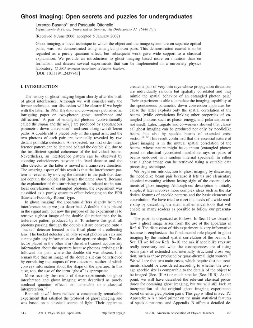
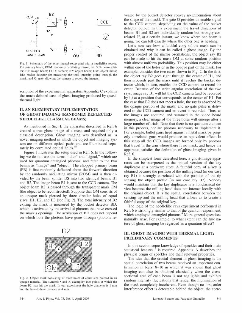
Figure 1 illustrates the setup used in Ref. 6. In the follow-ing we do not use the terms “idler” and “signal,” which areused for quantum entangled photons, and refer to the twobeams as “image” and “object.” The chopped primary beam�PB� is first randomly deflected about the forward directionby the randomly oscillating mirror �ROM� and is then di-vided by the beam splitter BS into two identical beams B1and B2. The image beam B1 is sent to the CCD camera. Theobject beam B2 is passed through the transparent mask OM�the object to be reconstructed�. Suppose that OM consists ofan opaque mask pierced by three circular holes of equalsizes, H1, H2, and H3 �see Fig. 2�. The total intensity of B2exiting the mask is measured by the bucket detector BD,which is activated by the arrival of photons that have crossedthe mask’s openings. The activation of BD does not dependon which hole the photons have gone through �photons re-
Fig. 1. Schematic of the experimental setup used with a needlelike source.PB: primary beam; ROM: randomly oscillating mirror; BS: 50% beam split-ter; B1: image beam; CCD: camera; B2: object beam; OM: object mask;BD: bucket detector for measuring the total intensity going through themask; and G: gate allowing the camera to record the images.
Fig. 2. Object mask consisting of three holes of equal size pierced in anopaque material. The symbols • and � exemplify two points at which thebeam B2 may hit the mask. In our experiment the hole diameter is 1 mm
and the hole-to-hole distance is 4 mm.344 Am. J. Phys., Vol. 75, No. 4, April 2007
vealed by the bucket detector convey no information aboutthe shape of the mask�. The gate G provides an enable signalto the CCD camera, depending on the value of the bucketdetector output. In this experiment the travel directions ofbeams B1 and B2 are individually random but strongly cor-related. If, at a certain instant, we know where one beam isgoing, we can tell exactly where the other one is heading.
Let’s now see how a faithful copy of the mask can beobtained and why it can be called a ghost image. By theproper control of the mirror oscillations, the object ray B2can be made to hit the mask OM at some random positionwith almost uniform probability. This position may lie eitherwithin one of the holes or in the opaque part of the mask. Forexample, consider the two cases shown in Fig. 2. In the first,the object ray B2 goes right through the center of H1, andthen proceeds past the mask until it reaches the bucket de-tector which, in turn, enables the CCD camera to record theevent. Because of the strict angular correlation of the tworays, image ray B1 will hit the CCD camera �and be recordedby it� at a position that corresponds to the center of H1. Forthe case that B2 does not meet a hole, the ray is absorbed bythe opaque portion of the mask, and no gate pulse is deliv-ered to the CCD camera and no event is recorded. Thus, asthe images are acquired and summed in the video boardmemory, a clear image of the three holes will emerge after alarge number of trials. Note that there is no quantum elementin this process, nor are photons necessary to implement it.For example, bullet pairs fired against a metal mask by prop-erly correlated guns would produce an equivalent effect. Inthis setup all the CCD images are formed only by photonsthat travel in the arm where there is no mask, and hence theapparatus satisfies the definition of ghost imaging given inRef. 6.
In the simplest form described here, a ghost-image appa-ratus can be interpreted as the optical version of the keyduplicator at a hardware store. A faithful copy of a key isobtained because the position of the milling head �in our caseray B1� is strongly correlated with the position of the tipsensing the object profile �in our case ray B2�. Nobodywould maintain that the key duplicator is a nonclassical de-vice because the milling head does not interact locally withthe original object. It is the spatial correlation between thesensing tip and the milling head that allows us to create afaithful copy of the original key.
The logic of the needlelike rays experiment performed inRef. 6 is strikingly similar to that of the quantum experiment,which employed entangled photons.4 More general questionsnaturally arise. For example, to what extent can the true na-ture of ghost imaging be regarded as a quantum effect?
III. GHOST IMAGING WITH THERMAL LIGHT:PRELIMINARY COMMENTS
In this section some knowledge of speckles and their mainstatistical features12 is required. Appendix A describes thephysical origin of speckles and their relevant properties.
The idea that the crucial element in ghost imaging is thespatial correlation of two beams received an important con-firmation in Refs. 8–10 in which it was shown that ghostimaging can also be obtained classically when the cross-sectional area of each beam is not negligible and exhibitsrandom intensity fluctuations that render the illumination ofthe mask completely incoherent. Even though no first order
interference effect is detectable behind the object, the corre-344Lorenzo Basano and Pasquale Ottonello
lation of the two beams lets a faithful image of the apertureemerge by properly designed processing, as explained in thefollowing.
At first sight, the goal of obtaining a ghost image usingextended incoherent beams might seem hopeless. Recall thatthe success of the experiment in Ref. 6 relies on the fact thatthe beam pairs in their apparatus are pointlike and correlated.So even though the CCD camera does not receive photonsthat went through the mask, it records the position of theirtwins that are translated with respect to the former by a fixedamount �which is also the secret of ghost imaging producedby entangled photon pairs�. This explanation of ghost imag-ing is simple as the key duplicator analogy reveals. If theneedlelike rays of Sec. II are replaced by beams of nonzerocross section, each beam’s cross section exhibits a randomintensity structure �speckles�, and the beam cross sections arelarger than the object to be copied. In this case the pointreconstruction of the image that is justified in Ref. 6 can nolonger be invoked.
We emphasize the essential change that takes place whenwe shift from needlelike rays to extended speckle beams.With needlelike rays, each frame contributes to the final im-age with a single bright dot whose position is inside an areathat corresponds geometrically to one of the holes. Brightdots falling outside the three hole areas cannot activate thecamera gate �see Fig. 2�. Ideally, the camera accumulatesbright dots according to a noiseless reconstruction, that is,there will be light inside the hole images and dark outsidethem.
With speckle beams, each frame grabbed by the CCDcamera is a random collection of bright and dark patches�speckles� covering an area larger than the mask. In eachframe there may be light where the mask image necessitatesdark, which implies the occurrence of a large amount ofnoise; it is difficult to visualize how the sum of such randomand noisy images will be able to reproduce the ordered pat-tern of the mask. An explanation of this successful reproduc-tion requires subtle statistical considerations that we willnow describe.
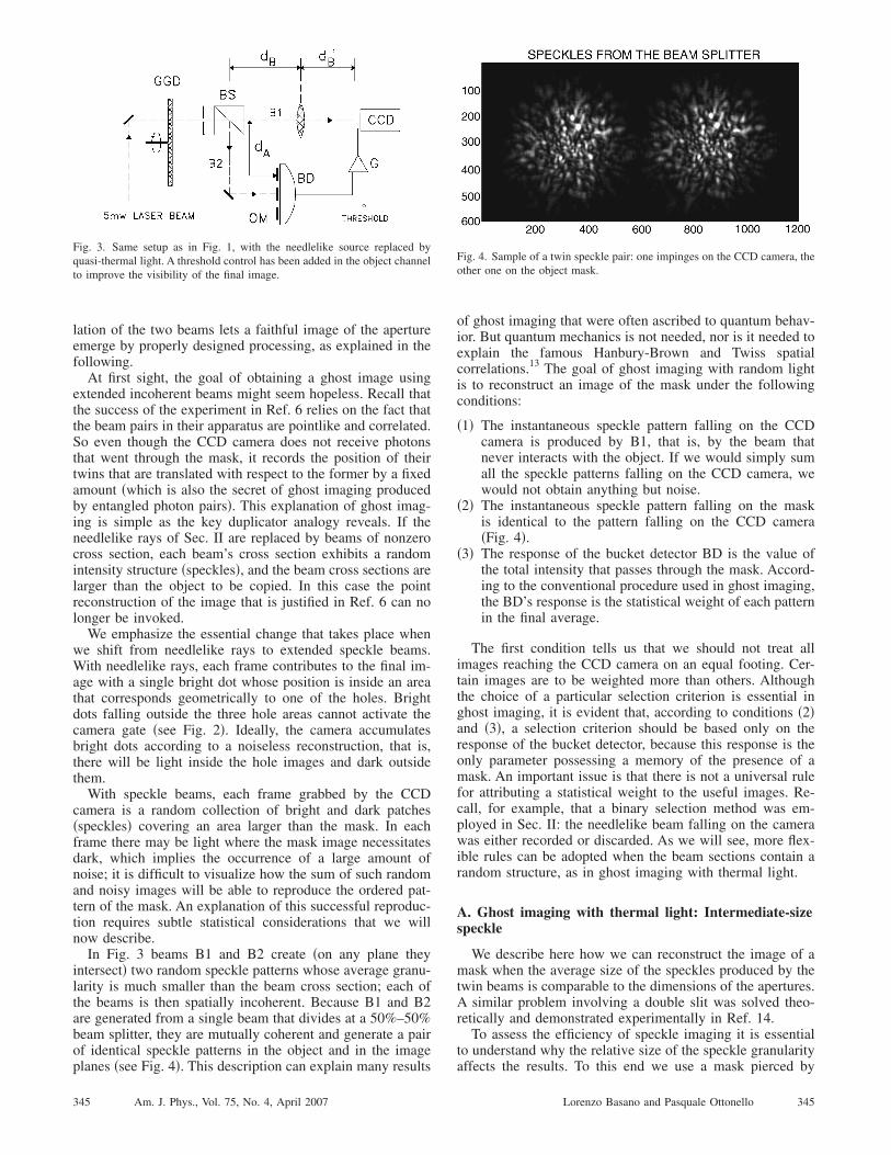
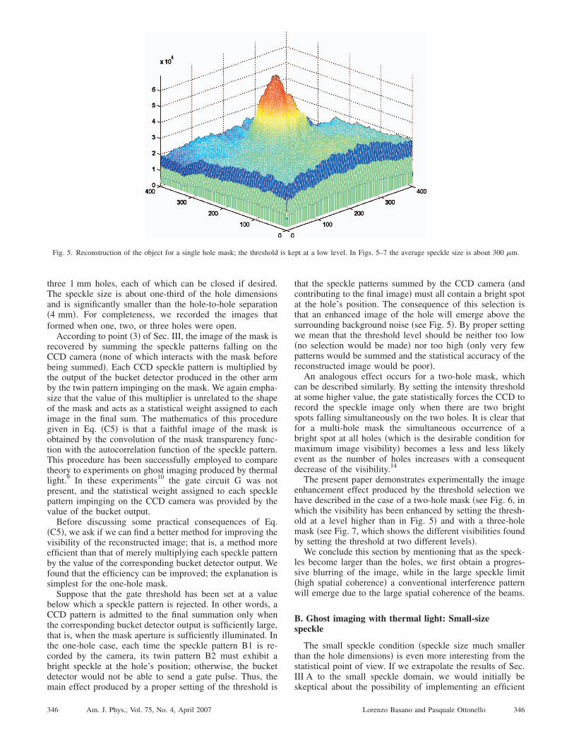
In Fig. 3 beams B1 and B2 create �on any plane theyintersect� two random speckle patterns whose average granu-larity is much smaller than the beam cross section; each ofthe beams is then spatially incoherent. Because B1 and B2are generated from a single beam that divides at a 50%–50%beam splitter, they are mutually coherent and generate a pairof identical speckle patterns in the object and in the image
Fig. 3. Same setup as in Fig. 1, with the needlelike source replaced byquasi-thermal light. A threshold control has been added in the object channelto improve the visibility of the final image.
planes �see Fig. 4�. This description can explain many results
345 Am. J. Phys., Vol. 75, No. 4, April 2007
of ghost imaging that were often ascribed to quantum behav-ior. But quantum mechanics is not needed, nor is it needed toexplain the famous Hanbury-Brown and Twiss spatialcorrelations.13 The goal of ghost imaging with random lightis to reconstruct an image of the mask under the followingconditions:
�1� The instantaneous speckle pattern falling on the CCDcamera is produced by B1, that is, by the beam thatnever interacts with the object. If we would simply sumall the speckle patterns falling on the CCD camera, wewould not obtain anything but noise.
�2� The instantaneous speckle pattern falling on the maskis identical to the pattern falling on the CCD camera�Fig. 4�.
�3� The response of the bucket detector BD is the value ofthe total intensity that passes through the mask. Accord-ing to the conventional procedure used in ghost imaging,the BD’s response is the statistical weight of each patternin the final average.
The first condition tells us that we should not treat allimages reaching the CCD camera on an equal footing. Cer-tain images are to be weighted more than others. Althoughthe choice of a particular selection criterion is essential inghost imaging, it is evident that, according to conditions �2�and �3�, a selection criterion should be based only on theresponse of the bucket detector, because this response is theonly parameter possessing a memory of the presence of amask. An important issue is that there is not a universal rulefor attributing a statistical weight to the useful images. Re-call, for example, that a binary selection method was em-ployed in Sec. II: the needlelike beam falling on the camerawas either recorded or discarded. As we will see, more flex-ible rules can be adopted when the beam sections contain arandom structure, as in ghost imaging with thermal light.
A. Ghost imaging with thermal light: Intermediate-sizespeckle
We describe here how we can reconstruct the image of amask when the average size of the speckles produced by thetwin beams is comparable to the dimensions of the apertures.A similar problem involving a double slit was solved theo-retically and demonstrated experimentally in Ref. 14.
To assess the efficiency of speckle imaging it is essentialto understand why the relative size of the speckle granularity
Fig. 4. Sample of a twin speckle pair: one impinges on the CCD camera, theother one on the object mask.
affects the results. To this end we use a mask pierced by
345Lorenzo Basano and Pasquale Ottonello
three 1 mm holes, each of which can be closed if desired.The speckle size is about one-third of the hole dimensionsand is significantly smaller than the hole-to-hole separation�4 mm�. For completeness, we recorded the images thatformed when one, two, or three holes were open.
According to point �3� of Sec. III, the image of the mask isrecovered by summing the speckle patterns falling on theCCD camera �none of which interacts with the mask beforebeing summed�. Each CCD speckle pattern is multiplied bythe output of the bucket detector produced in the other armby the twin pattern impinging on the mask. We again empha-size that the value of this multiplier is unrelated to the shapeof the mask and acts as a statistical weight assigned to eachimage in the final sum. The mathematics of this proceduregiven in Eq. �C5� is that a faithful image of the mask isobtained by the convolution of the mask transparency func-tion with the autocorrelation function of the speckle pattern.This procedure has been successfully employed to comparetheory to experiments on ghost imaging produced by thermallight.9 In these experiments10 the gate circuit G was notpresent, and the statistical weight assigned to each specklepattern impinging on the CCD camera was provided by thevalue of the bucket output.
Before discussing some practical consequences of Eq.�C5�, we ask if we can find a better method for improving thevisibility of the reconstructed image; that is, a method moreefficient than that of merely multiplying each speckle patternby the value of the corresponding bucket detector output. Wefound that the efficiency can be improved; the explanation issimplest for the one-hole mask.
Suppose that the gate threshold has been set at a valuebelow which a speckle pattern is rejected. In other words, aCCD pattern is admitted to the final summation only whenthe corresponding bucket detector output is sufficiently large,that is, when the mask aperture is sufficiently illuminated. Inthe one-hole case, each time the speckle pattern B1 is re-corded by the camera, its twin pattern B2 must exhibit abright speckle at the hole’s position; otherwise, the bucketdetector would not be able to send a gate pulse. Thus, the
Fig. 5. Reconstruction of the object for a single hole mask; the threshold
main effect produced by a proper setting of the threshold is
346 Am. J. Phys., Vol. 75, No. 4, April 2007
that the speckle patterns summed by the CCD camera �andcontributing to the final image� must all contain a bright spotat the hole’s position. The consequence of this selection isthat an enhanced image of the hole will emerge above thesurrounding background noise �see Fig. 5�. By proper settingwe mean that the threshold level should be neither too low�no selection would be made� nor too high �only very fewpatterns would be summed and the statistical accuracy of thereconstructed image would be poor�.
An analogous effect occurs for a two-hole mask, whichcan be described similarly. By setting the intensity thresholdat some higher value, the gate statistically forces the CCD torecord the speckle image only when there are two brightspots falling simultaneously on the two holes. It is clear thatfor a multi-hole mask the simultaneous occurrence of abright spot at all holes �which is the desirable condition formaximum image visibility� becomes a less and less likelyevent as the number of holes increases with a consequentdecrease of the visibility.14
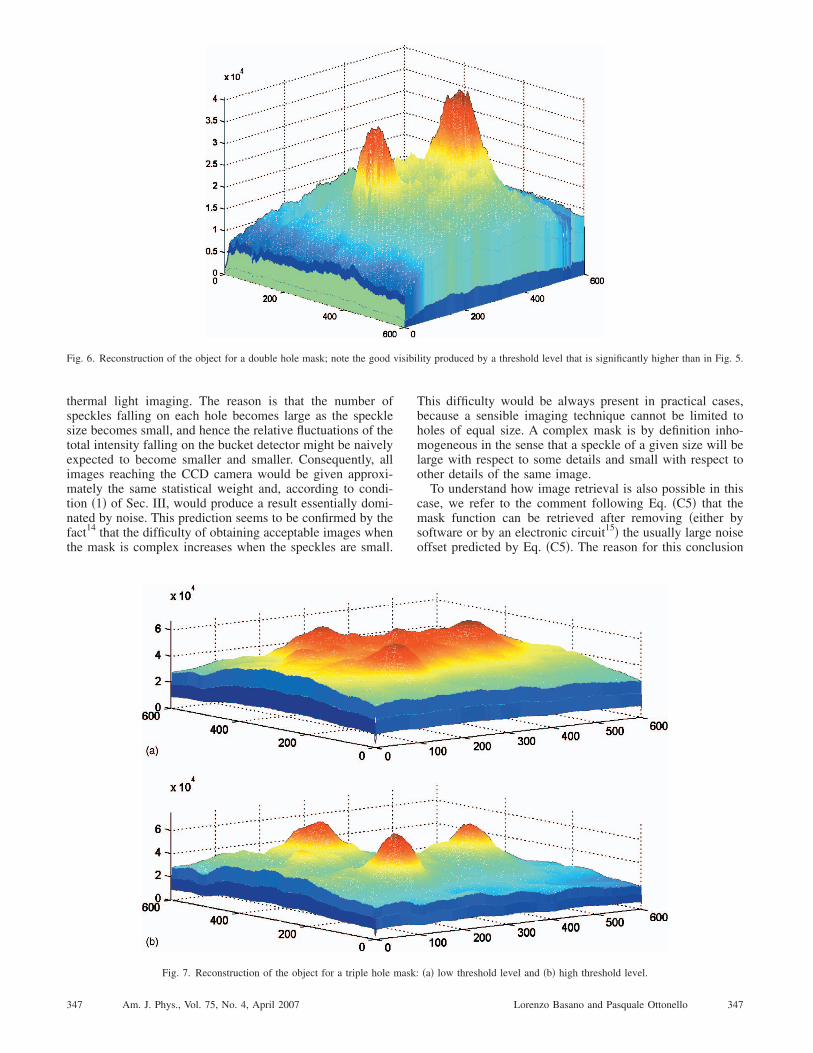
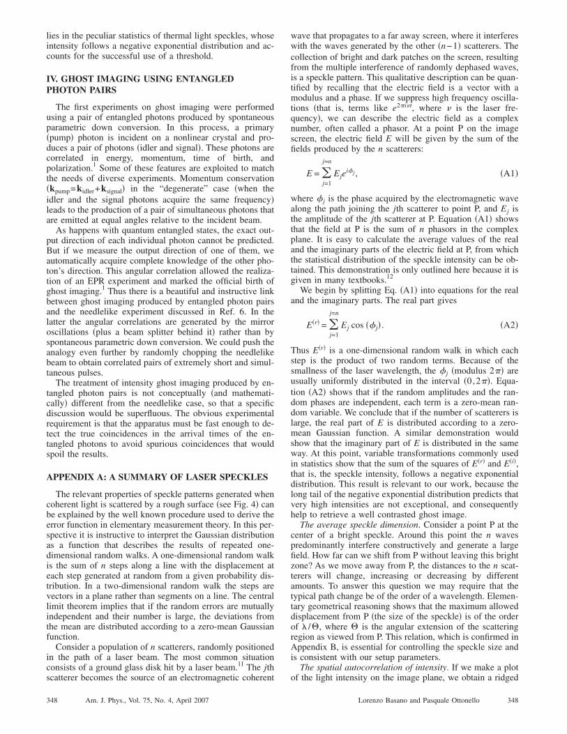
The present paper demonstrates experimentally the imageenhancement effect produced by the threshold selection wehave described in the case of a two-hole mask �see Fig. 6, inwhich the visibility has been enhanced by setting the thresh-old at a level higher than in Fig. 5� and with a three-holemask �see Fig. 7, which shows the different visibilities foundby setting the threshold at two different levels�.
We conclude this section by mentioning that as the speck-les become larger than the holes, we first obtain a progres-sive blurring of the image, while in the large speckle limit�high spatial coherence� a conventional interference patternwill emerge due to the large spatial coherence of the beams.
B. Ghost imaging with thermal light: Small-sizespeckle
The small speckle condition �speckle size much smallerthan the hole dimensions� is even more interesting from thestatistical point of view. If we extrapolate the results of Sec.III A to the small speckle domain, we would initially be
pt at a low level. In Figs. 5–7 the average speckle size is about 300 �m.
is keskeptical about the possibility of implementing an efficient
346Lorenzo Basano and Pasquale Ottonello
isibi
thermal light imaging. The reason is that the number ofspeckles falling on each hole becomes large as the specklesize becomes small, and hence the relative fluctuations of thetotal intensity falling on the bucket detector might be naivelyexpected to become smaller and smaller. Consequently, allimages reaching the CCD camera would be given approxi-mately the same statistical weight and, according to condi-tion �1� of Sec. III, would produce a result essentially domi-nated by noise. This prediction seems to be confirmed by thefact14 that the difficulty of obtaining acceptable images whenthe mask is complex increases when the speckles are small.
Fig. 6. Reconstruction of the object for a double hole mask; note the good v
Fig. 7. Reconstruction of the object for a triple hole mask:
347 Am. J. Phys., Vol. 75, No. 4, April 2007
This difficulty would be always present in practical cases,because a sensible imaging technique cannot be limited toholes of equal size. A complex mask is by definition inho-mogeneous in the sense that a speckle of a given size will belarge with respect to some details and small with respect toother details of the same image.
To understand how image retrieval is also possible in thiscase, we refer to the comment following Eq. �C5� that themask function can be retrieved after removing �either bysoftware or by an electronic circuit15� the usually large noiseoffset predicted by Eq. �C5�. The reason for this conclusion
lity produced by a threshold level that is significantly higher than in Fig. 5.
�a� low threshold level and �b� high threshold level.
347Lorenzo Basano and Pasquale Ottonello
lies in the peculiar statistics of thermal light speckles, whoseintensity follows a negative exponential distribution and ac-counts for the successful use of a threshold.
IV. GHOST IMAGING USING ENTANGLEDPHOTON PAIRS
The first experiments on ghost imaging were performedusing a pair of entangled photons produced by spontaneousparametric down conversion. In this process, a primary�pump� photon is incident on a nonlinear crystal and pro-duces a pair of photons �idler and signal�. These photons arecorrelated in energy, momentum, time of birth, andpolarization.1 Some of these features are exploited to matchthe needs of diverse experiments. Momentum conservation�kpump=kidler+ksignal� in the “degenerate” case �when theidler and the signal photons acquire the same frequency�leads to the production of a pair of simultaneous photons thatare emitted at equal angles relative to the incident beam.
As happens with quantum entangled states, the exact out-put direction of each individual photon cannot be predicted.But if we measure the output direction of one of them, weautomatically acquire complete knowledge of the other pho-ton’s direction. This angular correlation allowed the realiza-tion of an EPR experiment and marked the official birth ofghost imaging.1 Thus there is a beautiful and instructive linkbetween ghost imaging produced by entangled photon pairsand the needlelike experiment discussed in Ref. 6. In thelatter the angular correlations are generated by the mirroroscillations �plus a beam splitter behind it� rather than byspontaneous parametric down conversion. We could push theanalogy even further by randomly chopping the needlelikebeam to obtain correlated pairs of extremely short and simul-taneous pulses.
The treatment of intensity ghost imaging produced by en-tangled photon pairs is not conceptually �and mathemati-cally� different from the needlelike case, so that a specificdiscussion would be superfluous. The obvious experimentalrequirement is that the apparatus must be fast enough to de-tect the true coincidences in the arrival times of the en-tangled photons to avoid spurious coincidences that wouldspoil the results.
APPENDIX A: A SUMMARY OF LASER SPECKLES
The relevant properties of speckle patterns generated whencoherent light is scattered by a rough surface �see Fig. 4� canbe explained by the well known procedure used to derive theerror function in elementary measurement theory. In this per-spective it is instructive to interpret the Gaussian distributionas a function that describes the results of repeated one-dimensional random walks. A one-dimensional random walkis the sum of n steps along a line with the displacement ateach step generated at random from a given probability dis-tribution. In a two-dimensional random walk the steps arevectors in a plane rather than segments on a line. The centrallimit theorem implies that if the random errors are mutuallyindependent and their number is large, the deviations fromthe mean are distributed according to a zero-mean Gaussianfunction.
Consider a population of n scatterers, randomly positionedin the path of a laser beam. The most common situationconsists of a ground glass disk hit by a laser beam.11 The jth
scatterer becomes the source of an electromagnetic coherent348 Am. J. Phys., Vol. 75, No. 4, April 2007
wave that propagates to a far away screen, where it interfereswith the waves generated by the other �n−1� scatterers. Thecollection of bright and dark patches on the screen, resultingfrom the multiple interference of randomly dephased waves,is a speckle pattern. This qualitative description can be quan-tified by recalling that the electric field is a vector with amodulus and a phase. If we suppress high frequency oscilla-tions �that is, terms like e2�i�t, where � is the laser fre-quency�, we can describe the electric field as a complexnumber, often called a phasor. At a point P on the imagescreen, the electric field E will be given by the sum of thefields produced by the n scatterers:
E = �j=1
j=n
Ejei�j , �A1�
where � j is the phase acquired by the electromagnetic wavealong the path joining the jth scatterer to point P, and Ej isthe amplitude of the jth scatterer at P. Equation �A1� showsthat the field at P is the sum of n phasors in the complexplane. It is easy to calculate the average values of the realand the imaginary parts of the electric field at P, from whichthe statistical distribution of the speckle intensity can be ob-tained. This demonstration is only outlined here because it isgiven in many textbooks.12
We begin by splitting Eq. �A1� into equations for the realand the imaginary parts. The real part gives
E�r� = �j=1
j=n
Ej cos �� j� . �A2�
Thus E�r� is a one-dimensional random walk in which eachstep is the product of two random terms. Because of thesmallness of the laser wavelength, the � j �modulus 2�� areusually uniformly distributed in the interval �0,2��. Equa-tion �A2� shows that if the random amplitudes and the ran-dom phases are independent, each term is a zero-mean ran-dom variable. We conclude that if the number of scatterers islarge, the real part of E is distributed according to a zero-mean Gaussian function. A similar demonstration wouldshow that the imaginary part of E is distributed in the sameway. At this point, variable transformations commonly usedin statistics show that the sum of the squares of E�r� and E�i�,that is, the speckle intensity, follows a negative exponentialdistribution. This result is relevant to our work, because thelong tail of the negative exponential distribution predicts thatvery high intensities are not exceptional, and consequentlyhelp to retrieve a well contrasted ghost image.
The average speckle dimension. Consider a point P at thecenter of a bright speckle. Around this point the n wavespredominantly interfere constructively and generate a largefield. How far can we shift from P without leaving this brightzone? As we move away from P, the distances to the n scat-terers will change, increasing or decreasing by differentamounts. To answer this question we may require that thetypical path change be of the order of a wavelength. Elemen-tary geometrical reasoning shows that the maximum alloweddisplacement from P �the size of the speckle� is of the orderof � /�, where � is the angular extension of the scatteringregion as viewed from P. This relation, which is confirmed inAppendix B, is essential for controlling the speckle size andis consistent with our setup parameters.
The spatial autocorrelation of intensity. If we make a plot
of the light intensity on the image plane, we obtain a ridged348Lorenzo Basano and Pasquale Ottonello
surface containing hills �bright speckles� and valleys �darkspeckles�. Because the cause of these corrugations is the in-terference of many waves coming from randomly locatedradiators, we cannot expect any regularity in the positions ofthe hills. This impossibility suggests that the only relevantspatial correlation is between a hill and itself. Thus if wedefine a correlation function by evaluating the average of theproduct I�x�I�x+�� as a function of �, we will obtain a hillcentered around �=0, which decreases to a noisy constant. Itis also obvious that the horizontal extension of the centralhill is the average size of the speckle grains. It is for thisreason that when the speckles become very small, the spatialautocorrelation of the intensity reduces to a pronounced andnarrow peak around �=0. In ghost imaging this result isimportant for obtaining well defined images �see Sec. III B�.
The temporal coherence of fluctuating speckle patterns.Suppose that the ground glass disk we have mentioned isinitially nonrotating and thus the speckle pattern in the imageplane is still. We now set the disk in motion. Some of thescatterers will begin exiting the laser spot and will be re-placed by other scatterers that were initially outside it. Thischange alters the values of some of the random phases.When most of the original scatterers have been replaced bynew ones, the new speckle pattern will be completely unre-lated to the initial pattern. As the speckle pattern evolves, thelight intensity at a given point P fluctuates with a character-istic time that is the time required for a relevant fraction ofthe scatterers to move out of the laser spot. This time is thecoherence time c of the process, a measure of the temporalextent over which we can predict the future values of thelight intensity at a given point.
APPENDIX B: DESCRIPTION OF THE APPARATUS
It is convenient to fix the values of the optical parametersstarting from the spatial resolution of the camera. The spatialresolution will be good if the mask apertures �in our case, thehole diameters� are larger than the pixel size. To obtain afinal image of good visibility, a speckle size should be usedthat is about three times smaller than the width of the maskaperture. It is easy to satisfy the latter condition because thespeckle size is related to the diameter of the laser beam im-pinging on the ground glass disk and to the distance of themask from the disk;11 both parameters can be varied withinwide ranges.
In our experiment the choices of about 0.3 mm for thespeckle size and 1 mm for the hole diameter were a conse-quence of the low spatial resolution of the only camera avail-able to us at that time �18 lines/mm�. The camera is a Prox-itronic BV2561 intensifier optically coupled to a ThomsonTH79KA96A. The light intensity generated by a 5 mW laserlets us use any common inexpensive camera with identicalresults. In a typical student laboratory the camera with a PCinterfaced digitizing board is the most expensive component.The bucket detector BD is a common photodiode with anactive area larger than the whole object mask OM.
After adjusting the speckle size to obtain good visibility,we required the distances dA, dB, and dB� to satisfy
1
dB − dA+
1
dB�=
1
F, �B1�
where F is the focal length of the lens in Fig. 3. The elec-
tronic circuit allows the detector to gate the image intensifier349 Am. J. Phys., Vol. 75, No. 4, April 2007
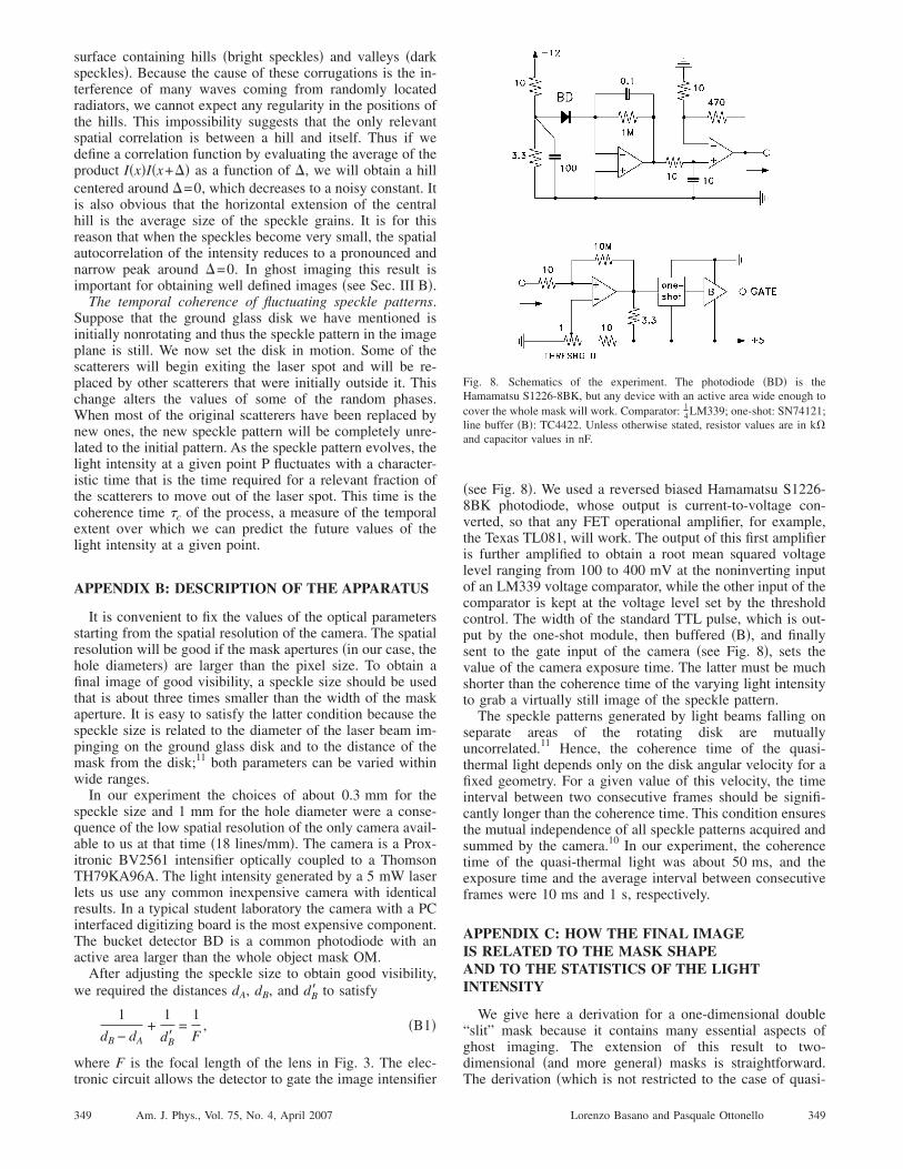
�see Fig. 8�. We used a reversed biased Hamamatsu S1226-8BK photodiode, whose output is current-to-voltage con-verted, so that any FET operational amplifier, for example,the Texas TL081, will work. The output of this first amplifieris further amplified to obtain a root mean squared voltagelevel ranging from 100 to 400 mV at the noninverting inputof an LM339 voltage comparator, while the other input of thecomparator is kept at the voltage level set by the thresholdcontrol. The width of the standard TTL pulse, which is out-put by the one-shot module, then buffered �B�, and finallysent to the gate input of the camera �see Fig. 8�, sets thevalue of the camera exposure time. The latter must be muchshorter than the coherence time of the varying light intensityto grab a virtually still image of the speckle pattern.
The speckle patterns generated by light beams falling onseparate areas of the rotating disk are mutuallyuncorrelated.11 Hence, the coherence time of the quasi-thermal light depends only on the disk angular velocity for afixed geometry. For a given value of this velocity, the timeinterval between two consecutive frames should be signifi-cantly longer than the coherence time. This condition ensuresthe mutual independence of all speckle patterns acquired andsummed by the camera.10 In our experiment, the coherencetime of the quasi-thermal light was about 50 ms, and theexposure time and the average interval between consecutiveframes were 10 ms and 1 s, respectively.
APPENDIX C: HOW THE FINAL IMAGEIS RELATED TO THE MASK SHAPEAND TO THE STATISTICS OF THE LIGHTINTENSITY
We give here a derivation for a one-dimensional double“slit” mask because it contains many essential aspects ofghost imaging. The extension of this result to two-dimensional �and more general� masks is straightforward.
Fig. 8. Schematics of the experiment. The photodiode �BD� is theHamamatsu S1226-8BK, but any device with an active area wide enough tocover the whole mask will work. Comparator: 1
4LM339; one-shot: SN74121;line buffer �B�: TC4422. Unless otherwise stated, resistor values are in kand capacitor values in nF.
The derivation �which is not restricted to the case of quasi-
349Lorenzo Basano and Pasquale Ottonello
thermal light� assumes the conventional ghost imaging re-trieval based on the raw output of the bucket detector, with-out recourse to the threshold-based statistical weightdiscussed in Sec. III A.
Denote by M�x� the transparency function of the mask,that is, M�x�=1 where the mask is transparent and M�x�=0elsewhere. Now consider a sequence �Si
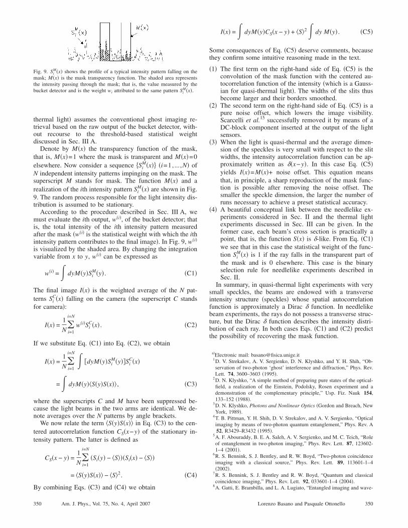
M�x�� �i=1, ... ,N� ofN independent intensity patterns impinging on the mask. Thesuperscript M stands for mask. The function M�x� and arealization of the ith intensity pattern Si
M�x� are shown in Fig.9. The random process responsible for the light intensity dis-tribution is assumed to be stationary.
According to the procedure described in Sec. III A, wemust evaluate the ith output, w�i�, of the bucket detector; thatis, the total intensity of the ith intensity pattern measuredafter the mask �w�i� is the statistical weight with which the ithintensity pattern contributes to the final image�. In Fig. 9, w�i�
is visualized by the shaded area. By changing the integrationvariable from x to y, w�i� can be expressed as
w�i� =� dyM�y�SiM�y� . �C1�
The final image I�x� is the weighted average of the N pat-terns Si
C�x� falling on the camera �the superscript C standsfor camera�:
I�x� =1
N�i=1
i=N
w�i�SiC�x� . �C2�
If we substitute Eq. �C1� into Eq. �C2�, we obtain
I�x� =1
N�i=1
i=N � �dyM�y�SiM�y��Si
C�x�
=� dyM�y�S�y�S�x� , �C3�
where the superscripts C and M have been suppressed be-cause the light beams in the two arms are identical. We de-note averages over the N patterns by angle brackets.
We now relate the term S�y�S�x� in Eq. �C3� to the cen-tered autocorrelation function CS�x−y� of the stationary in-tensity pattern. The latter is defined as
CS�x − y� =1
N�i=1
i=N
�Si�y� − S��Si�x� − S�
= S�y�S�x� − S2. �C4�
Fig. 9. SiM�x� shows the profile of a typical intensity pattern falling on the
mask; M�x� is the mask transparency function. The shaded area representsthe intensity passing through the mask; that is, the value measured by thebucket detector and is the weight wi attributed to the same pattern Si
M�x�.
By combining Eqs. �C3� and �C4� we obtain
350 Am. J. Phys., Vol. 75, No. 4, April 2007
I�x� =� dyM�y�CS�x − y� + S2� dy M�y� . �C5�
Some consequences of Eq. �C5� deserve comments, becausethey confirm some intuitive reasoning made in the text.
�1� The first term on the right-hand side of Eq. �C5� is theconvolution of the mask function with the centered au-tocorrelation function of the intensity �which is a Gauss-ian for quasi-thermal light�. The widths of the slits thusbecome larger and their borders smoothed.
�2� The second term on the right-hand side of Eq. �C5� is apure noise offset, which lowers the image visibility.Scarcelli et al.15 successfully removed it by means of aDC-block component inserted at the output of the lightsensors.
�3� When the light is quasi-thermal and the average dimen-sion of the speckles is very small with respect to the slitwidths, the intensity autocorrelation function can be ap-proximately written as ��x−y�. In this case Eq. �C5�yields I�x�=M�x�+ noise offset. This equation meansthat, in principle, a sharp reproduction of the mask func-tion is possible after removing the noise offset. Thesmaller the speckle dimension, the larger the number ofruns necessary to achieve a preset statistical accuracy.
�4� A beautiful conceptual link between the needlelike ex-periments considered in Sec. II and the thermal lightexperiments discussed in Sec. III can be given. In theformer case, each beam’s cross section is practically apoint, that is, the function S�x� is �-like. From Eq. �C1�we see that in this case the statistical weight of the func-tion Si
M�x� is 1 if the ray falls in the transparent part ofthe mask and is 0 elsewhere. This case is the binaryselection rule for needlelike experiments described inSec. II.
In summary, in quasi-thermal light experiments with verysmall speckles, the beams are endowed with a transverseintensity structure �speckles� whose spatial autocorrelationfunction is approximately a Dirac � function. In needlelikebeam experiments, the rays do not possess a transverse struc-ture, but the Dirac � function describes the intensity distri-bution of each ray. In both cases Eqs. �C1� and �C2� predictthe possibility of recovering the mask function.
a�Electronic mail: [email protected]. V. Strekalov, A. V. Sergienko, D. N. Klyshko, and Y. H. Shih, “Ob-servation of two-photon ‘ghost’ interference and diffraction,” Phys. Rev.Lett. 74, 3600–3603 �1995�.
2D. N. Klyshko, “A simple method of preparing pure states of the optical-field, a realization of the Einstein, Podolsky, Rosen experiment and ademonstration of the complementary principle,” Usp. Fiz. Nauk 154,133–152 �1988�.
3D. N. Klyshko, Photons and Nonlinear Optics �Gordon and Breach, NewYork, 1989�.
4T. B. Pittman, Y. H. Shih, D. V. Strekalov, and A. V. Sergienko, “Opticalimaging by means of two-photon quantum entanglement,” Phys. Rev. A52, R3429–R3432 �1995�.
5A. F. Abouraddy, B. E. A. Saleh, A. V. Sergienko, and M. C. Teich, “Roleof entanglement in two-photon imaging,” Phys. Rev. Lett. 87, 123602-1–4 �2001�.
6R. S. Bennink, S. J. Bentley, and R. W. Boyd, “Two-photon coincidenceimaging with a classical source,” Phys. Rev. Lett. 89, 113601-1–4�2002�.
7R. S. Bennink, S. J. Bentley and R. W. Boyd, “Quantum and classicalcoincidence imaging,” Phys. Rev. Lett. 92, 033601-1–4 �2004�.
8
A. Gatti, E. Brambilla, and L. A. Lugiato, “Entangled imaging and wave-350Lorenzo Basano and Pasquale Ottonello
particle duality: from the microscopic to the macroscopic realm,” Phys.Rev. Lett. 90, 133603-1–4 �2003�.
9A. Gatti, E. Brambilla, M. Bache, and L. A. Lugiato, “Correlated imag-ing, quantum and classical,” Phys. Rev. A 70, 013802-1–10 �2004�.
10F. Ferri, D. Magatti, A. Gatti, M. Bache, E. Brambilla, and L. A. Lugiato,“High-resolution ghost image and ghost diffraction experiments withthermal light,” Phys. Rev. Lett. 94, 183602-1–4 �2005�.
11
W. Martienssen and E. Spiller, “Coherence and fluctuations in light351 Am. J. Phys., Vol. 75, No. 4, April 2007
beams,” Am. J. Phys. 32, 919–926 �1964�.12See for example, J. W. Goodman, Statistical Optics �Wiley, New York,
1985�, pp. 44–50.13P. W. Milonni and J. H. Eberly, Lasers �Wiley, New York, 1988�, p. 577.14A. Valencia, G. Scarcelli, M. D’Angelo, and Y. Shih, “Two-photon im-
aging with thermal light,” Phys. Rev. Lett. 94, 063601-1–4 �2005�.15G. Scarcelli, V. Berardi, and Y. Shih, “Phase-conjugate mirror via two-
photon thermal light imaging,” Appl. Phys. Lett. 88, 061106-1–3 �2006�.
351Lorenzo Basano and Pasquale Ottonello