giant scour-fills in ancient channel-lobe transition zones
TRANSCRIPT

This is a repository copy of Giant scour-fills in ancient channel-lobe transition zones: Formative processes and depositional architecture.
White Rose Research Online URL for this paper:http://eprints.whiterose.ac.uk/91390/
Version: Accepted Version
Article:
Hofstra, M, Hodgson, DM, Peakall, J et al. (1 more author) (2015) Giant scour-fills in ancient channel-lobe transition zones: Formative processes and depositional architecture. Sedimentary Geology, 329. 98 - 114. ISSN 0037-0738
https://doi.org/10.1016/j.sedgeo.2015.09.004
© 2015. This manuscript version is made available under the CC-BY-NC-ND 4.0 license http://creativecommons.org/licenses/by-nc-nd/4.0/
[email protected]://eprints.whiterose.ac.uk/
Reuse
Unless indicated otherwise, fulltext items are protected by copyright with all rights reserved. The copyright exception in section 29 of the Copyright, Designs and Patents Act 1988 allows the making of a single copy solely for the purpose of non-commercial research or private study within the limits of fair dealing. The publisher or other rights-holder may allow further reproduction and re-use of this version - refer to the White Rose Research Online record for this item. Where records identify the publisher as the copyright holder, users can verify any specific terms of use on the publisher’s website.
Takedown
If you consider content in White Rose Research Online to be in breach of UK law, please notify us by emailing [email protected] including the URL of the record and the reason for the withdrawal request.

Giant scour-fills in ancient channel-lobe transition zones: formative 1
processes and depositional architecture 2
M. Hofstra1*, D.M. Hodgson1, J. Peakall
1 and S.S. Flint
2 3
1 Stratigraphy Group, Department of Earth and Environment, 4
University of Leeds, Leeds, LS2 9JT, UK 5
2 Stratigraphy Group, School of Earth, Atmospheric and 6
Environmental Sciences, University of Manchester, Manchester, 7
Oxford Road, M13 9PL, UK 8
*Corresponding author: Menno Hofstra; [email protected]; phone: 9
+44 (0) 7979 870 252 7 10
Co-authors emails: [email protected]; [email protected]; 11
Abstract 13
Scours are common features of modern deep-marine seascapes, 14
particularly downstream of the mouths of slope channels within 15
channel-lobe transition zones (CLTZs). Their dimensions can exceed 16
hundreds of metres in width and length, and tens of metres in 17
depth. However, the stratigraphic architecture of the infill of these 18
erosional bedforms is rarely described from the rock record and no 19
large (>100 m width) scours have been described in detail from 20
exhumed CLTZs. Here, the infill of two erosional features (0.5-1 km 21
long and 15-20 m thick) from the Permian Karoo Basin succession, 22
South Africa, are presented from palaeogeographically well-23
constrained CLTZs; one from Fan 3 in the Tanqua depocentre and 24
one from Unit A5 in the Laingsburg depocentre. The basal erosion 25

surfaces of the features are asymmetric with steep, undulating, and 26
composite upstream margins, and low gradient simple downstream 27
margins. The basal infill consists of thin-bedded siltstone and 28
sandstone beds cut by closely-spaced scours; these beds are 29
interpreted as partially reworked fine grained tails of bypassing 30
flows with evidence for flow deflection. The erosional features are 31
interpreted as giant scour-fills. The internal architecture suggests 32
different evolutionary histories for each case. The Unit A5 scour-fill 33
shows a simple cut-and-fill history with lateral and upward 34
transitions from siltstone- to sandstone-prone deposits. In contrast, 35
the Fan 3 scour-fill shows headward erosion and lengthening of the 36
scour surface suggesting temporal changes in the interaction 37
between turbidity currents and the scour surface. This relationship 38
could support the occurrence of a hydraulic jump during part of the 39
fill history, while the majority of the fill represents deposition from 40
subcritical flows. Diversity in scour preservation mechanisms could 41
explain the variety in depositional histories. The architecture, 42
sedimentary facies and palaeoflow patterns of the scour-fills are 43
distinctly different to well documented adjacent basin-floor 44
channel-fills at the same stratigraphic levels. The recognition of 45
scour-fills helps to constrain their sedimentological and stratigraphic 46
expression in the subsurface, and to improve our understanding of 47
the stratigraphic architecture of channel-lobe transition zones. 48
Keywords 49
channel-lobe transition; base-of-slope; giant scours; scour-fill; 50
bypass; facies characteristics; Karoo Basin 51

52
1. Introduction 53
Large scours are readily recognised erosional bedforms on modern 54
deep-marine seabeds (e.g., Palanques et al., 1995; Morris et al., 55
1998; Wynn et al., 2002a; Bonnel et al., 2005; Fildani et al., 2006; 56
Macdonald et al., 2011a; Maier et al., 2011; Shaw et al., 2013; 57
Covault et al., 2014; Paul et al., 2014). Commonly, these scours are 58
concentrated within channel-lobe transition zones (CLTZs), a 59
relatively unconfined area dominated by sediment bypass that 60
separates the mouths of channel feeder systems from lobes (Mutti 61
and Normark, 1987, 1991; Kenyon et al., 1995; Wynn et al., 2002a). 62
Scours commonly form fields consisting of many individual and 63
coalesced scours (e.g., Wynn et al., 2002a; Macdonald et al., 2011a; 64
Shaw et al., 2013). The occurrence of scours is commonly 65
interpreted (Komar, 1971; Mutti and Normark, 1987, 1991; Garcia 66
and Parker, 1989; Garcia, 1993; Macdonald et al., 2011a; Ito et al., 67
2014), and occasionally demonstrated (Sumner et al., 2013), to be 68
related to flows that have undergone a hydraulic jump 69
(transformation from supercritical to subcritical flow conditions), 70
triggered by changes in flow velocity and/or density. These changes 71
in flow behaviour are predicted to occur in base-of-slope to basin 72
floor transitions where there are abrupt change in gradient and 73
degree of confinement (e.g. Alexander et al., 2008; Ito et al., 2008). 74
While observations of small-scale scours and megaflutes in ancient 75
systems are abundant (e.g. Macdonald et al., 2011a), large-scale 76

features are not well documented. Megascours associated with 77
Mass Transport Deposits (MTDs) have been constrained by various 78
seismic examples (e.g., Moscardelli, 2006; Sawyer et al., 2009; Ortiz-79
Karpf et al., 2015) on slope settings and in some outcrop examples 80
from lower slope to base-of-slope deposits (Pickering and Hilton, 81
1998, their Fig.63; Lee et al., 2004; Dakin et al., 2012). In these 82
cases, erosional depressions are tens of metres deep and filled with 83
chaotic deposits. In contrast, large scour-fills in turbidite systems are 84
rarely identified in outcrop, therefore their evolution and 85
architecture are poorly constrained. Dimensions of turbidite-filled 86
scours reported from outcrop-related studies include the Ross 87
Formation (Ireland) with typical dimensions of 0.3-3.5 m in depth 88
and 1 to 45 m in length (Chapin et al., 1994; Elliott, 2000a, 2000b; 89
Lien et al., 2003; Macdonald et al., 2011b), the Albian Black Flysch 90
(Spain) with 1-5 m deep 5-50 m wide scours (Vicente-Bravo and 91
Robles, 1995), the Cerro Toro Formation (Chile) with scour depths of 92
metres and widths of tens of metres (Winn and Dott, 1979; Jobe et 93
al.,2009) and the Windermere Group with scours up to several 94
decimetres deep and several tens of centimetres to many tens of 95
metres wide (Terlaky et al., 2015); composite scours up to several 96
metres deep are reported in the Macigno Costiero Fm., Italy 97
(Eggenhuisen et al., 2011) and the Boso Pensinsula (Japan) with 98
erosional features filled with backset bedding up to 140 m wide and 99
10 m deep (Ito et al., 2014). These dimensions are an order of 100
magnitude smaller than the scour dimensions described from 101
modern systems (> 10 m depth and > 100 m width) (e.g. Wynn et al., 102

2002a; Macdonald et al., 2011a). Scour-fills may be 103
underrepresented in the rock record because outcrop limitations 104
mean that they may have been misidentified as channel-fills due to 105
cross-sectional similarity (Mutti and Normark, 1987, 1991; Wynn et 106
al., 2002a; Normark et al., 2009). Furthermore, the stratigraphic 107
expression of the CLTZ, including scour-fills, is rarely fully exposed or 108
well-constrained in ancient systems (Mutti and Normark, 1987, 109
1991; Gardner et al., 2003; Ito et al., 2014; van der Merwe et al., 110
2014). 111
Here, the morphology and depositional architecture of two 112
exhumed large-scale erosional scours from the Permian succession 113
of the Karoo Basin, South Africa, are described in detail: one 114
example from Fan 3 of the Tanqua depocentre and the other from 115
Unit A within the Laingsburg depocentre. Previous mapping has 116
constrained the palaeogeographic context of both locations to areas 117
where there is a down-dip architectural change from channel- to 118
lobe-dominated deposits (Morris et al., 2000; Van der Werff and 119
Johnson, 2003; Sixsmith et al., 2004; Hodgson et al., 2006; Jobe et 120
al., 2012; Prélat and Hodgson, 2013). The presented examples 121
exhibit different sedimentological and architectural characteristics 122
compared to basin floor channel-fills in adjacent stratigraphy. The 123
objectives of this paper are to: i) evaluate the origin of these 124
distinctive erosional features, ii) compare the erosional and 125
depositional history to channel-fills, iii) develop recognition criteria 126
for scour-fills in outcrop, iv) discuss the role of erosional bedforms in 127
improving our understanding of the stratigraphic expression of 128

CLTZs within ancient submarine systems, and v) aid investigations 129
into the role of hydraulic jumps in deep-water bedform 130
development. Accurate recognition and description of large-scale 131
erosional architectural elements has important implications for the 132
robust application of outcrop studies to improve reservoir models 133
and reduce uncertainty in subsurface investigations. 134
135
2. Regional Setting 136
The Karoo Basin is one of a number of Late Palaeozoic to Mesozoic 137
basins that formed at the southern margin of Gondwana (De Wit 138
and Ransome, 1992; Veevers et al., 1994; López-Gamundi and 139
Rossello, 1998). The Karoo Basin has been interpreted traditionally 140
as a retroarc foreland basin withsubsidence purely caused by the 141
loading of the Cape Fold Belt (e.g., Johnson, 1991; Cole, 1992; 142
Visser, 1993; Veevers et al., 1994; Catuneanu et al., 1998). More 143
recent interpretations suggest that subsidence during the Permian 144
was caused by dynamic topography effects due to subduction 145
(Tankard et al., 2009) in a pre-foreland basin stage. The southwest 146
Karoo Basin is subdivided into the Laingsburg and the Tanqua 147
depocentres (Fig. 1) of which the deepwater fill of both depocentres 148
is represented by the Ecca Group. The Ecca Group (Fig. 2) comprises 149
a 2 km-thick shallowing-upward succession from distal basin-floor 150
through submarine slope to shelf-edge and shelf deltaic settings 151
(Wickens, 1994; Flint et al., 2011). 152

2.1 Tanqua depocentre 153
This study focuses on part of Fan 3 of the Skoorsteenberg 154
Formation, which is one of four sand-rich basin-floor fan systems 155
(Fig. 2) (Bouma and Wickens, 1991, 1994; Wickens and Bouma, 156
2000; Johnson et al., 2001). Fan 3 is the most extensively studied fan 157
system of the Skoorsteenberg Formation, as it shows the most 158
complete outcrop extent (Hodgson et al., 2006). The Fan 3 study 159
area (Kleine Riet Fontein) is located in the southwestern corner of 160
the Fan 3 outcrop, which is the most updip location (Fig. 1,3A). An 161
integrated outcrop and research borehole dataset has established 162
the isopach thickness of Fan 3, and the relative spatial and temporal 163
distribution of sedimentary facies, architectural elements and 164
palaeocurrents (Johnson et al., 2001; Hodgson et al., 2006; Prélat et 165
al., 2009; Groenenberg et al., 2010). The axis of the system is 166
located farther to the east along depositional strike in the 167
Ongeluksriver area (Fig. 3A) and is characterised by distributive 168
basin floor channel systems with overall palaeocurrent to the 169
north/north-east(Van der Werff and Johnson, 2003; Sullivan et al., 170
2004; Hodgson et al., 2006; Luthi et al. 2006).The distributive 171
character of the channel-systems at Ongeluksriver (Fig. 3A), the 172
more deeply erosional character of the channelsin overlying Fan 4 173
and Unit 5, and the thinning to the south (Oliveira et al., 2009), all 174
suggest that the southwestern outcrop-limit of Fan 3 is a proximal 175
off-axis base-of-slope setting setting (Johnson et al., 2001, Van der 176
Werff and Johnson, 2003; Luthi et al., 2006; Hodgson et al., 2006; 177
Jobe et al., 2012). The Kleine Riet Fontein area was previously 178

studied in detail by Jobe et al. (2012) and interpreted as an area 179
receiving unconfined flows, supported by the wide spatial 180
distribution of numerous metre-scale scour features. 181
2.2 Laingsburg depocentre 182
The proximal basin floor system of the Laingsburg Formation is 183
divided into Units A and B (Sixsmith et al., 2004; Brunt et al., 2013) 184
(Fig.2). The 350 m thick Unit A comprises sand-prone sub-units A1-185
A7, which are separated by regionally extensive mudstones 186
(Sixsmith et al., 2004; Flint et al., 2011; Prélat and Hodgson, 2013). 187
TエW ゲデ┌SキWS ラ┌デIヴラヮ キゲ キミ デエW けWキノェWヴエラ┌デげ ;ヴW; within Unit A5, a 100 188
m thick and tens of km-long package of sandstones and siltstones on 189
the northern limb of the post-depositional Baviaans syncline (Figs. 1, 190
3B), close to the town of Laingsburg. Palaeogeographically, the 191
study area is located in the axis of the A5 system on the basin floor 192
(Sixsmith et al. 2004) (Fig.1). The large number of sand-rich channel-193
fills that characterise the upper part of A5 in this area point to a 194
location close to the base-of-slope and/or close to the mouths of 195
large distributary channels (Sixsmith et al., 2004; Prélat and 196
Hodgson, 2013). 197
198
3. Methodology and datasets 199
Stratigraphic correlations were completed in the field using closely-200
spaced sedimentary logs, photomontages, and walking out key 201
surfaces with a handheld GPS to construct architectural panels. In 202

the Fan 3 KRF study area (4.6 km2), a total of 20 sedimentary logs 203
was collected (Fig. 3A). More than 550 palaeocurrent 204
measurements, primarily from ripple cross-lamination, were 205
collected and tied to specific stratigraphic units. Due to the inherent 206
variability in direction of ripple cross-laminations, a high number of 207
measurements was needed and only surfaces with a clear dominant 208
orientation were measured. The dip direction of ripple foresets was 209
measured where possible to ensure an accurate palaeoflow 210
direction. The main outcrop face consists of a 3.5 km long N-S 211
depositional dip section. Several E-W orientated gullies to the east 212
of the main outcrop face provide additional depositional strike 213
control (Fig. 3A). Thin siltstone packages within the regional 214
claystones between Fan 2 and Fan 3 provide local correlation 215
datums. 216
Within the Wilgerhout area of Unit A5 a total of 17 sedimentary logs 217
along a ~ 500m depositional dip (W-E) section was collected (Fig. 218
3B). The regional A5 to A6 mudstone (Sixsmith et al., 2004; Flint et 219
al., 2011; Cobain et al., 2015) was used as the datum for all 220
correlations. A total of 44 palaeocurrents was measured solely from 221
ripple cross-laminations and give an average eastward directed 222
palaeoflow (082°). Where the tectonic tilt was significant(> 20°) the 223
azimuth of well exposed planar foresets was measured and 224
restored. 225
Facies associations have been determined based on previous Karoo 226
Basin studies (Johnson et al., 2001; Van der Werff and Johnson 227

2003; Grecula et al., 2003; Hodgson et al., 2006; Brunt et al., 2013) 228
and extensive study of the Fan 3 and Unit A system. Bounding and 229
erosion surfaces have been identified with the help of bed 230
truncation and the absence of normal-grading structures at bed 231
tops. 232
4. Facies associations 233
The deep-water deposits of the Karoo Basin show a limited grain 234
size distribution ranging from claystone to fine-grained sandstones. 235
Both Fan 3 and Unit A consist of mainly thin-bedded siltstones and 236
very fine- to fine-grained sandstones. Flow conditions were 237
interpreted from the described facies characteristics. A total of six 238
distinct facies associations was identified based on field 239
observations and are described in detail below. 240
4.1 Thick structureless sandstones (Fa1) 241
Thick (>1 m) fine-grained sandstone beds with little to no internal 242
structure can form amalgamated sandstone packages up to 5 m 243
thick and tens to hundreds metres wide/long, that are commonly 244
tabular. Weak normal grading is observed at bed tops, where 245
planar- and ripple-cross lamination may be preserved. Locally, bed 246
bases and/or tops can show planar laminations and/or banding 247
(alternating lighter and darker bands, see section 4.3). The 248
sandstone beds can contain a minor amount of dispersed sub-249
angular mudclasts (Fig. 4A). Flame structures and tool (drag) marks 250
are observed at bed bases. 251

These deposits are interpreted as rapid fall-out from sand rich high-252
density turbidity currents (Kneller and Branney, 1995; Stow and 253
Johansson, 2002) with clasts representing traction-transported 254
bedload (See section 4.2 and 4.3 for interpretation of planar 255
laminated and banded intervals). Flame structures are associated 256
with syn-depositional dewatering (Stow and Johansson, 2002). 257
4.2 Medium-bedded laminated sandstones (Fa2) 258
These medium- to thick-bedded (0.2 to 3 m thick), very fine-grained 259
to fine-grained, sandstones show various sedimentary structures. 260
Ripple lamination, in particular climbing ripple lamination, is 261
abundant (25-70% of all laminated sandstones), showing high angles 262
of climb with stoss-side preserved lamination (>45° on stoss-side 263
preserved laminae) (Fig. 4B). Some beds show a clear upward 264
increase in the angle of climb and proportion of stoss-side laminae 265
preservation. Where planar lamination is present it is commonly at 266
bed bases. Bases of thicker-bedded structured beds are sharp and 267
the basal part, in comparison to the remaining laminated part of the 268
bed, is commonly structureless. Bed tops always show abrupt 269
normal grading to fine siltstone. Bed geometries can show lateral 270
thickness variations on 10-s of metres scale. 271
High angles of climb and stoss-side preservation in ripple-laminated 272
sandstones are indicative of rapid unidirectional aggradation rates 273
(Jopling and Walker, 1968; Allen, 1973; Jobe et al., 2012; Morris et 274
al., 2014). When sedimentation rate exceeds the rate of erosion at 275
the ripple reattachment point, the stoss-side deposition is preserved 276

and aggradational bedforms develop (Allen, 1973). This style of 277
tractional deposition is attributed to rapid deceleration of the flow 278
and deposition from moderate-to low-concentration turbidity 279
currents (Allen, 1973; Jobe et al., 2012). The planar laminations 280
within the structured sandstones are interpreted to be deposited 281
under upper stage plane bed conditions (Allen, 1984; Talling et al., 282
2012). 283
4.3 Banded sandstones (Fa3) 284
This facies association comprises medium- to thick-bedded fine-285
grained sandstones (20 to 200 cm, on average 40 cm), with diffuse 286
laminae of over 1 cm thickness (Fig. 4C,5A2). This style of lamination 287
is characterised by an alternation between lighter and darker bands, 288
and is referred to as banded sandstones. Lighter bands are well 289
sorted and quartz-rich, whereas plant fragments and/or mudstone 290
clasts and micaceous materials are commonly found within the 291
poorly sorted darker bands. The banding is dominantly planar and 292
parallel to sub-parallel, but can be mildly wavy. Internal cm-scale 293
scour surfaces are common, as is loading at the bases of lighter 294
bands. Within thicker beds dominated by banded sandstone beds, 295
the bases are structureless and sharp. 296
Banded sandstones differ from planar-laminated sandstones due to 297
the thickness of the laminae (>1 cm), the thickness of the laminated 298
interval within individual event beds (>1 m) and the absence of any 299
major grain size differences between laminae. The observations 300
indicate highly concentrated, aggradational but fluctuating flow 301

conditions. These conditions are present during deposition in 302
traction carpets under high-density turbidity currents (Lowe, 1982; 303
Sumner et al., 2008, 2012; Talling et al., 2012; Cartigny et al., 2013) 304
and have not been linked to a generic flow regime. This is 305
comparable to the H2 division of Haughton et al. (2009) and the 306
Type 2 tractional structures of Ito et al. (2014). The internal 307
truncations that have been observed can be explained by quasi-308
steady behaviour within a stratified flow, however the extent and 309
size of these truncations (up to m-scale) support more drastically 310
waxing and waning flow behaviour. Combined with the thickness of 311
individual beds within this facies group, these deposits support an 312
interpretation of high aggradation rate and/or possibly long-313
duration of individual events. 314
4.4 Thin-bedded sandstones and siltstones (Fa4) 315
Thin (<20 cm) very fine-grained sandstones are interbedded with 316
laminated siltstones (<1 cm to 5 cm). Ripple lamination, including 317
low-angle climbing ripple lamination, is common within the 318
sandstone beds. This facies group can be subdivided into 1) tabular 319
sandstones with planar and ripple laminations (Fa4-1), and 2) 320
lenticular sandstones and siltstones associated with numerous 321
centimetre-scale erosion surfaces (Fa4-2; Figs. 4D, 5A1,5A4). Locally, 322
Fa4-2 sandstone beds contain mudstone clasts (<1 cm) (Fig. 5A3) 323
and can be associated with mudstone and siltstone clast 324
conglomerates (max 0.5 m thick, 1-2 m long) that are clast-325
supported with a fine-grained sandstone matrix (Fig. 5B3). Within 326

Unit A5, thin (<5 cm) medium-grained, poorly sorted lenticular 327
sandstone beds that are at least 10 m long (Fig. 5B1) are associated 328
with Fa4-2 siltstones. The Fa4-2 siltstones of Unit A5 are thicker 329
bedded (>3 cm) (Fig. 5B1). 330
The tabular bed geometry and predominance of current ripple 331
lamination in Fa 4-1 are interpreted to indicate deposition from 332
lower phase flow conditions within sluggish dilute turbidity currents 333
(e.g., Allen, 1984). The occasional planar laminated sandstone 334
indicates upper phase flow conditions (Best and Bridge, 1992) but 335
with a transition to lower phase flow conditions due to ripple-336
laminated tops. 337
The Fa 4-2 group supports a higher energy environment compared 338
to the FA4-1 group, which is interpreted based on the local presence 339
of mudstone clasts and the numerous erosion surfaces. This facies 340
association is interpreted to represent a period dominated by 341
sediment bypass (e.g., Stevenson et al., 2015). The fine-grained 342
siltstone deposits of the Fa4-2 group are interpreted to represent 343
the tails of bypassing turbidity currents and continued reworking of 344
the substrate by long lived turbidity currents, similar to channel-345
margin deposits (Grecula et al., 2003, Brunt et al., 2013). The 346
mudstone clast conglomerates are interpreted as bedload material, 347
derived from a mud-rich substrate, and therefore represent lag 348
deposits of highly energetic bypassing turbidity currents. Sediment 349
bypass zones can show fluctuations between depositional, erosional 350
and bypass processes when being around the erosion-deposition 351

threshold (e.g., Wynn et al., 2002a; Ito et al., 2014; Stevenson et al., 352
2015). This facies association shares many similarities to the 353
ゲWSキマWミデ H┞ヮ;ゲゲ a;IキWゲ キSWミデキaキWS ┘キデエキミ デエW CLTZげゲ ラa ゲ;ミS-detached 354
lobe systems in the Laingsburg area (van der Merwe et al., 2014). 355
These fluctuations might result in the interbedding of siltstones and 356
sandstones, including thin and lenticular medium-grained sandstone 357
beds, and multiple erosion surfaces. The presence of unusually thick 358
siltstone beds, and medium-grained sandstones, which are very rare 359
in the Ecca Group, within the Unit A5 Fa4-2 facies group is evidence 360
of localised deposition. The climbing ripple lamination within thin-361
bedded sandstones indicates rapid aggradation rates (Allen, 1973; 362
Jobe et al., 2012). 363
4.5 Soft sediment deformed (SSD) deposits (Fa5) and claystones 364
(Fa6) 365
The Fa5 facies group is represented by localised tightly folded and 366
contorted heterolithic units (0.2-0.5 m thick) of thin-bedded 367
siltstones and sandstones (Fig. 5B2). Fa5 represents a minor portion 368
of the infill (<1%) and occurs only within the basal infill towards the 369
margins of both features, and in close association with Fa4-2, rarely 370
exceeding 2 m in length. Thick, regionally extensive units of Fa6 371
claystones occur as drapes to the deepwater sandstone units in both 372
depocetres. 373
Due to their marginal location and limited proportions, the 374
contorted thin bed units are interpreted to represent local 375
remobilisations, above erosional relief. Fa 6 represents condensed 376

intervals of hemipelagic deposition, during periods of regional 377
shutdown in coarse-grained sediment supply (Hodgson et al., 2006; 378
Luthi et al., 2006; Flint et al., 2011; van der Merwe et al., 2014). 379
380
5. Depositional Architecture 381
Both features are defined by composite and asymmetric basal 382
erosion surfaces that exceed the extent of the exposures (>350 m 383
long in A5; >1000 m long in Fan 3) and incise 15-20 m into 384
underlying deposits. The consistent palaeoflow directions of 385
underlying and overlying deposits indicate that the updip margins 386
are highly irregular, undulating and orientated sub-parallel to 387
regional palaeoflow directions. The Fan 3 exposure is orientated 388
150-330° with a 340° average palaeoflow at this location (n = 435). 389
The Unit A5 exposure is orientated 075-255° with a 082° average 390
palaeoflow (n = 44). The type and distribution of sedimentary facies 391
and internal stacking patterns differ between the two cases, and are 392
discussed separately. 393
5.1 Fan 3 feature; Tanqua depocentre 394
The location of the Fan 3 erosional feature (Fig. 6) is in the middle of 395
a north-south orientated outcrop of proximal off-axis deposits in the 396
Kleine Riet Fontein area (Figs. 1, 6). Mapping of thickness, facies, 397
and system-scale sedimentary architecture with the lack of channel-398
fills in this area compared to the Ongeluks river area to the south-399
east supports this as a proximal off-axis environment (Johnson et al., 400

2001; Hodgson et al., 2006; Jobe et al., 2012) (Fig.3A). The overall 401
palaeoflow is northwards (Fig. 7). The underlying deposits can be 402
subdivided into a sandstone-prone package dominated by Fa2 and 403
an overlying siltstone-prone package dominated by Fa4 (Figs. 6 and 404
7). A minor stratigraphic change in mean palaeoflow is identified 405
between these two packages, from NNE (033°) to NNW (336°) (Fig. 406
7). The feature in the Kleine Riet Fontein area shows an erosional 407
cut into the siltstone-prone package. All deposits within Fan 3 below 408
the basal erosion surface of the studied feature extend beyond the 409
study area and are therefore more laterally extensive . The basal 410
erosion surface forms a series of metre-scale steps on the steep 411
(max. 50°) updip southern margin (Figs. 5A5, 6). The full geometry of 412
the northern margin is obscured, but the overall thinning of the fill 413
suggests a low-angle confining surface (Fig. 6). Sedimentary sections 414
taken towards the east (Fig. 3A) of the main N-S profile (Fig. 6) 415
indicate eastward shallowing of the basal erosion surface and infill 416
directed perpendicular to regional palaeoflow (Fig. 8A). 417
The architecture of the fill is characterised by abrupt changes in bed 418
thickness and multiple truncation surfaces (Figs. 6, 9,10), and can be 419
subdivided into two distinct infill packages based on changes in 420
facies proportions and architecture across key bounding surfaces 421
(Fig. 6, 8B). The lower package is up to 6.5m thick and is subdivided 422
into two distinct elements (1 and 2) based on an internal truncation 423
surface and abrupt changes in bed thickness (Fig. 6). Both elements 424
comprise (Fig. 8B) thin-bedded siltstones and climbing ripple 425
laminated sandstones (Fa4-2) containing small (1-4 cm) mudstone-426

chips and minor (20-40 cm thick) folded thin-bedded deposits (Fa5). 427
The lower package is only present in the northern part of the fill. 428
The upper package is up to 12 m thick and is subdivided into five 429
different infill elements (3-7) (Figs. 6, 9, 10) based on abrupt 430
stratigraphic facies transitions and internal erosion surfaces. The 431
upper package elements are predominantlymedium- to thick-432
bedded structured sandstones (Fig. 8B) with upward steepening 433
climbing ripple-lamination and increased stoss-side preservation 434
(Fa2) (Fig. 4B). Each of these elements, varying between 2 and 7.5 m 435
in thickness, shows lateral thickness and facies changes. Within the 436
individual elements there are no clear vertical trends, however the 437
combination of the upper and lower packages together forms a 438
stepped coarsening and thickening upward profile (Fig. 8B) within 439
the axis of the feature. The lower elements in the upper package (3, 440
4,5) are more laterally restricted (Figs. 9,10) and show more 441
substantial bed thickness variability compared to the upper 442
elements (6 and 7). Element 4, and to a lesser extent element 6, 443
thicken where the underlying elements thin (Fig. 6 and 9). Facies 444
within the upper package are uniform with a dominance of climbing-445
ripple laminated sandstone (Fa2) and a transition to more thinly-446
bedded deposits (Fa4) towards the margins of all elements (Fig. 6) 447
where not truncated. Elements 5 and 7 contain some banded 448
sandstones (Fa3) directly overlying the basal erosion surface at the 449
southern margin (Fig. 5A2), which show a northward facies 450
transition to structureless sandstone (Fa1). Elements 3, 4 and 5 451
(Figs. 9 and 10) show bedsets (3-7 m thick) that comprise four to five 452

metre-thick (0.5 to 2.0 m) dominantly climbing-ripple laminated 453
sandstone beds, which are interbedded with thin siltstones (<0.1 m). 454
They are thickest near the southern margin, and pinch or taper out 455
into thin siltstones (<5 cm) in a northward direction (over 50-150 m). 456
Successive pinchouts occur southward, such that the beds shingle 457
updip. Where normally graded sandstone beds thicken they 458
amalgamate, as can be seen in element 5 (Fig. 10B). Due to 459
accessibility issues, the exact orientation of the bedding is difficult 460
to measure directly, but outcrop sections of element 3 and 5 (Fig. 9 461
and 10) indicate a shallow southward (updip) depositional dip (a few 462
degrees). In addition, beds in element 3 dip upstream approximately 463
2-4° relative to the basal erosional surface (Fig. 9). Elements 6 and 7 464
do not preserve clear bed stacking patterns, although lateral 465
variability in bed thickness is observed. 466
The palaeoflow patterns within the erosional feature in the Kleine 467
Riet Fontein area are diverse and show lateral and stratigraphic 468
variations. The lower package preserves a dominant south-easterly 469
orientation (134°) within element 1 at its most southern limit, which 470
becomes more eastward (093°) within element 2 (Fig. 6, K7). 471
Severalhundred metres to the north, element 2 has a dominant NNE 472
to NE (025° に K8, 035° に K9; Figs. 6 and 7) palaeoflow direction. In 473
the upper package, there is a general NE to SE trend (096°) except 474
for element 7, which shows an overall NE direction (028°) at its 475
northern limit and a more NNW direction (345°) near its 476
southernmost limit (Fig. 6). The thin-bedded deposits above the 477

upper package have a NNE palaeoflow (028°, n = 57), consistent 478
with the underlying deposits and the regional trend. 479
A second large-scale erosional feature 800 m to the north (around 480
K13, Fig. 3A) is situated at the same stratigraphic level in Fan 3, and 481
shares many similarities in architecture and infill facies. The infill of 482
this erosive feature exhibits an average NNW-directed (330°) (n=17) 483
palaeoflow, similar to the underlying thin-bedded deposits. An 484
irregular erosion surface(~15°) has a measured ENE orientation 485
(070°), perpendicular to palaeoflow and overlain by structured 486
sandstones. Three hundred metres to the east, another erosion 487
surface (~6°) is approximately orientated NNW (335°), which is 488
parallel to the palaeoflow, and is evident from discordance in bed 489
dips within the thin-bedded deposits. The basal surface has a 490
minimum length of 500 m perpendicular to palaeoflow and cuts at 491
least 10 m into underlying deposits. Close to the western margin the 492
fill consists solely of Fa2 facies, but eastwards where the fill 493
thickens, it consists of a lower package of thin-bedded siltstones and 494
sandstones (Fa4-2) and an upper package of structured sandstones 495
(Fa2), that are locally amalgamated. 496
5.2 Unit A5 feature; Laingsburg depocentre 497
The erosional feature at Wilgerhout lies in the upper half of Unit A5 498
(60-70 m from the base) within a succession of stacked lobes locally 499
cut by sand-rich channel-forms (Prélat and Hodgson, 2013). A large 500
channel (>600 m wide and >15 m deep) filled by amalgamated 501
structureless sandstones (Fa1) is present at the top of the A5 502

succession in this location. The association of channels and lobes in 503
this area supports a base-of-slope setting, within the upper part of 504
the Unit A5 system based on regional mapping (Sixsmith et al., 2004; 505
Prélat and Hodgson, 2013). The exposure is limited to a 1 km long E-506
W orientated section. Regional palaeoflow patterns are towards the 507
ENE (Sixsmith et al., 2004), which is consistent with measurements 508
from the infill deposits (Fig. 11). The section shows a steep (2-50°) 509
and stepped western (updip) margin. 510
The fill consists of three distinct sedimentary packages. A lower 511
package (1.5-5 m thick) comprises thin-bedded siltstones with rare 512
banded or ripple laminated fine-grained sandstone beds (Fa4-2) (Fig. 513
11). Locally, thin (<30 cm) mudstone clast conglomerates directly 514
overlie the basal erosion surface. Multiple small-scale (<20 cm deep) 515
cross-cutting erosional surfaces incise into thin-bedded siltstones in 516
the basal ~0.5 m of the fill, but decrease towards the top. Thin (2-3 517
cm) and lenticular moderately sorted medium-grained sandstones 518
are present within the siltstones and individual normally graded 519
siltstone beds are thick (> 3 cm) (Fig. 5B1). The middle package (0.5-520
10 m thick) comprises medium-bedded banded (Fa3) and 521
structureless sandstones (Fa1) interbedded with siltstones, which 522
pass abruptly from sandstone-dominated to siltstone-dominated 523
(Fa4-2) at the western margin (Fig. 5B4). Some minor tightly folded 524
deposits (Fa5) (Fig. 5B2) occur within the siltstone dominated 525
western margin succession. The upper package (3-8.5 m thick) 526
comprises thick-bedded sharp-based structureless partially 527
amalgamated fine-grained sandstones (Fa1) interbedded with the 528

occasional banded sandstone and thin-bedded siltstone (Fig. 11). 529
This package extends beyond the limits of erosional confinement, 530
but increases in thickness above the deepest point of the basal 531
erosion surface. Within all three infill packages no clear vertical 532
stratigraphic trends have been observed. However, the combination 533
of the three infill packages together (Fig. 11B にW15) shows a step-534
wise coarsening- and thickening-upward trend above the basal 535
surface. Above the upper package a 4 metre thick fining- and 536
thinning-upwards unit can be observed (Fig. 11) from thick- to 537
medium-bedded dominantly structureless sandstones (Fa1) to thin-538
bedded sandstone and siltstone deposits (Fa 4). As these deposits 539
are tabular, they are not considered to be part of the fill. Up to 500 540
m west (updip) of the basal erosional surface at the same 541
stratigraphic level, a fine-grained thin-bedded package (1-2 m thick) 542
is characterised by multiple small-scale (10-20 cm) erosion surfaces, 543
thin sandstone beds, and abrupt bed thickness changes. 544
545
6. Discussion 546
6.1 Origin and infill of erosional features 547
The average palaeocurrents from underlying and overlying deposits 548
indicate that the large asymmetric erosion surfaces described from 549
Fan 3 (Tanqua) and Unit A5 (Laingsburg) are dip-sections (Figs. 3, 550
6,11). The steeper upstream surfaces dip at angles of 4-50° (Fan 3) 551
and 2-50° (Unit A5), with prominent metre-scale steps and multiple 552
erosion surfaces indicating the composite nature of the basal 553

surface. In the Kleine Riet Fontein area (Fan 3), the transverse to 554
downstream section is shallow (~3.5°) and smooth (Fig. 6), and 555
shows prominent asymmetry in three dimensions with shallowing of 556
the basal surface perpendicular to the regional palaeoflow (Fig. 557
10A). Palaeocurrents within the basal are diverse and at a high angle 558
(orientated N to SE) to underlying and overlying deposits (orientated 559
NNW), with palaeoflow differences of up to 180° (Fig. 7). 560
An asymmetric and composite basal erosional surface with stacked 561
smaller-scale elements could support an interpretation of a sinuous 562
submarine channel-fill. However, in a cut through a sinuous channel-563
fill the palaeocurrents would be expected to be dominantly parallel 564
to channel banks (dip sections) (Parsons et al., 2010; Wei et al., 565
2013; Sumner et al., 2014) and are only rarely described at high 566
angles to the basal surface (Pyles et al., 2012). Known exhumed 567
examples of outer bank deposits have relatively higher energy facies 568
such as conglomerates, and coarse-grained and/or amalgamated 569
sandstones (e.g., Young et al., 2003; Labourdette et al., 2007; 570
Hodgson et al., 2011; Janocko et al., 2013) compared to inner bank 571
deposits, which does not match with the observed distribution of 572
facies and the relatively low-energy character of the Kleine Riet 573
Fontein infill. Furthermore, channel sinuosity is predicted to be low 574
for the slope gradients of base-of-slope and basin-floor channel 575
bends (e.g., Clark et al., 1992 に close to 1.0 sinuosity at 1:1000 slope 576
angles), especially in sand-prone systems without levees and at mid-577
high palaeolatitudes (50-60°S) at which the Karoo system formed 578
(Peakall et al., 2012, 2013; Morris et al., 2014; Cossu et al., 2015). 579

Consequently, given the low predicted sinuosities it is unlikely that 580
channel bend facies would be at high angles to the regional slope. In 581
contrast, the morphology of the basal surface, the palaeocurrent 582
pattern, and distribution of sedimentary facies support an 583
interpretation of large-scale scour-fills, with prominent steep 584
headwalls and lower-angle downstream margins. In addition, 585
coarsening- and thickening-upwards trends as identified within both 586
features, considering the complete infill, are more readily explained 587
as a progradational trend (e.g., Macdonald et al., 2011b) than 588
channel-fills. Basin-floor channel-fills in the Ecca Group have been 589
described by several authors (e.g., Johnson et al., 2001; Sixsmith et 590
al., 2004; Sullivan et al., 2004; Brunt et al., 2013), and are 591
dominantly characterised by structureless sandstone, highly 592
amalgamated in the axis of the fills and more thin-bedded towards 593
the margins and top of the fills . Where well preserved, the basal 594
erosion surface and facies distribution of basin-floor channels are 595
symmetrical (Sullivan et al., 2004; Luthi et al., 2006), and typically 596
~250-350 m wide and 15-20 m thick (Pringle et al., 2010; Brunt et 597
al., 2013). The large-scale scour-fills described, therefore, are 598
distinctly different to the published examples of basin-floor channel 599
fills from the Karoo Basin in terms of their architecture, facies types 600
and distributions, and relationship of palaeoflow to the bounding 601
surface, as well as to sinuous channels from other settings. The 602
erosional feature within the Kleine Riet Fontein area of Fan 3 has 603
been previously interpreted as a channel-fill. Morris et al. (2000) 604
classified it as a crevasse channel-fill, while Van der Werff and 605
Johnson (2003) interpreted it as the distal depositional part of an 606
overbank channel-fill with a SE-NW orientation. Implicit in both 607
interpretations was that the depositional architecture is different to 608
the basin-floor channel-fills at the same stratigraphic level 7-8 km to 609
the east (e.g., Sullivan et al., 2004; Luthi et al., 2006). 610
The basal fine-grained fill (Fa4-2) in both scour-fills is interpreted to 611
indicate sediment bypass and the deposition of low-energy tails of 612
flows. The interpretation of thin-bedded deposits indicating 613
sediment bypass has been previously made for channel-fills (e.g., 614
Beaubouef and Friedmann, 2000; Grecula et al., 2003; Brunt et al., 615
2013; Stevenson et al., 2015). However the thicknesses of individual 616
siltstone beds (>3 cm) within the Unit A5 fill is distinctive, and is 617
interpreted to reflect the capture of flow tails in a scour depression, 618
in a similar manner to thick siltstones in internal levee successions 619
(Kane and Hodgson, 2011). In the Kleine Riet Fontein feature (Fan 3), 620
the diverse palaeoflow directions in the basal siltstone units 621
suggests deflection and spreadingl of flow at the upstream end. 622
Complex flow patterns are known to be associated with flutes and 623
scours (e.g., Eggenhuisen et al., 2011) with flows exhibiting a 624
recirculating separation cell that forms downstream of the scour lip 625
as the basal high velocity part of the flow is jetted over the 626
depression (Allen, 1971; Farhoudi and Smith, 1985; Karim and Ali, 627
2000). This may occur in both subcritical and supercritical flows. 628
When the palaeoflow patterns of element 2 (at K7, K8, and K9) are 629
compared with the streamline patterns of the spindle-shaped 630
erosional marks of Allen (1971), and assuming a scour orientated 631

with the flow direction of the underlying deposits (336°), there is a 632
close fit in terms of variance and spread (Fig. 12). Therefore, the 633
observed palaeoflow patterns can be explained by the presence of a 634
flow separation cell and the generation of reversed bedload 635
transport at the bottom of the flow when passing through the 636
depression (Fig. 12). 637
The second erosional feature located 800 m downstream of the 638
Kleine Riet Fontein scour is similar in architecture and fill. It shows 639
erosion and downcutting surfaces both perpendicular (10° cut to 640
330° palaeoflow) and parallel (335° cut to 330° palaeoflow) to 641
regional palaeoflow. The morphology suggests this second erosional 642
feature is also a large composite scour-fill (>300 m wide). As this 643
northern scour is atthe same stratigraphic level, it indicates there 644
may be a larger area of erosional bedforms present. This fits with 645
the interpretations of Jobe et al. (2012) defining the Kleine Riet 646
Fontein area as an area receiving unconfined flows. A spatial 647
distribution of multiple scour-fills in this proximal off-axis area 648
adjacent to distributive channels in Ongeluks River (Fig. 3) supports 649
the interpretation of a channel-lobe transition zone close to the 650
base-of-slope. 651
6.2 Flow-scour dynamics 652
The merging of multiple erosion surfaces at the steep and stepped 653
upstream margin of both scour-fills point to their composite origin, 654
with multiple flows shaping the morphology of the basal surface. 655
The basal successions of both scour-fills are similar. However, bed 656

architecture, stacking patterns, erosion surfaces, and facies of the 657
upper elements (3-7) in the Kleine Riet Fontein featurepoint to a 658
more complicated interaction between flow and seabed relief in a 659
later stage of scour evolution. 660
In the Unit A5 feature, the irregular basal surface suggests that after 661
initial development of the scour, the upstream margin was weakly 662
modified, with little evidence of headward erosion. Minor internal 663
erosion surfaces exist, but generally beds taper towards the 664
upstream margin. The stratigraphic transition from the siltstone- to 665
sandstone-prone deposits points to initial sediment bypass (multiple 666
erosion surfaces and medium-grained sandstone lenses) followed by 667
a period of aggradation (structureless Fa1 and banded sandstones 668
Fa3) as the depression filled. The passive depositional character of 669
these packages and the lack of supercritical bedforms, suggests a 670
subcritical nature for the infill. 671
In the case of the Kleine Riet Fontein scour, the evolution of the 672
scour is assessed from the architecture and stacking patterns of the 673
elements (Fig. 13).. The position of the upstream margin of the 674
scour during deposition of element 1 was downstream of the 675
current position of element 2, being deposited after another phase 676
of erosion, evident from the stepped basal erosional surface (Fig.6). 677
Element 3 shows a similar southward migration after reshaping of 678
the updip margin and only partially filled the depression. Element 4 679
is interpreted to have largely filled the accommodation in the 680
downstream and lateral part of the scour. This was truncated by 681

another erosional event that reshaped the updip margin and 682
removed large parts of element 2 and 3. Element 5 and 6 have 683
slightly erosional bases, but mostly infill available accommodation 684
by stacking in a downstream direction. Element 7 has a more 685
uniform thickness but modified the updip margin (Figs. 6 and 13). 686
The interpreted evolution of the basal surface suggests that the 687
initial scouring phase(s) may not be preserved due to sequential 688
deepening and widening of the scour.. The stacking of the elements 689
and internal erosion surfaces in the Kleine Riet Fontein scour-fill 690
indicate upstream migration (Fig. 13) and lengthening of the original 691
scour surface through headward erosion. Headward erosion, or 692
backward incision, occurs in both supercritical and subcritical flows 693
(e.g., Izumi and Parker, 2000; Hoyal and Sheets, 2009). The 694
sedimentary facies and bed geometries of the elements in the upper 695
package are characterised by stoss-side preserved steep climbing-696
ripple dominated sandstones that indicate rapid localised fallout 697
from relatively low-concentration turbidity currents. Climbing ripple 698
lamination extends across almost the whole length of the scour-fill 699
until in close proximity of the upstream head of the scour. The 700
shallow (a few degrees) upstream depositional dip observed in a 701
number of the infill elements (3, 4, 5)resemble backset bedding (Fig. 702
9). Backset bedding has been linked to abrupt changes in 703
confinement (Ito et al., 2014), associated with the occurrence of a 704
hydraulic jump (Jopling and Richardson, 1966; Lang and Winsemann, 705
2013; Cartigny et al., 2014; Ito et al. 2014). The backset deposits, 706
and the majority of the scour-fill, are characterised almost 707

exclusively by climbing ripple-lamination (Fa 2).These deposits may 708
be either the product of rapid settling from the downstream parts of 709
hydraulic jumps as the scour migrated headward, or the products of 710
subsequent infill by subcritical currents after being previously cut by 711
flows that underwent a hydraulic jump. The measurements of 712
hydraulic jumps over giant scours in a natural gravity current 713
demonstrate, however, that the hydraulic jump enhances upward 714
fluid movement for large distances downstream of the hydraulic 715
jump (Sumner et al., 2013), and therefore minimises sedimentation 716
within the scour. Additionally, the presence of climbing ripple 717
lamination very close to the head of the scour suggests that this 718
final phase was the product of depositional subcritical flows. In 719
combination with the lack of evidence for any depositional features 720
typical of supercritical conditions (supercritical bedforms), other 721
than the backset bedding in elements 3-5, this suggests that the 722
predominant fill of the scour was by subcritical flows. Thus the 723
inception, deepening, and sediment bypass phases of these giant 724
scours may well have been associated with hydraulic jumps in 725
supercritical flows, whilst their infill was dominantly the product of 726
later subcritical flows. This contrasts to the supercritical deposits 727
interpreted in other examples of backset bedding (Jopling and 728
Richardson, 1966; Lang and Winsemann, 2013; Cartigny et al., 2014; 729
Ito et al., 2014). 730
The infill character of the scour to the north of the main Kleine Riet 731
Fontein scour is very similar, with a lower siltstone-prone package 732
and an abrupt change into an upper climbing-ripple dominated 733

sandstone package. This suggests both features share a similar 734
depositional history, which could be due to an internal control 735
linked to an updip avulsion or an external control such as a 736
substantial change in turbidity current energy and/or size. Existing 737
local seabed depressions consisting of partially filled scours could 738
have triggered hydraulic jumps and subsequently reshaped their 739
morphology in a similar manner in both scours, followed by lower 740
energy subcritical flows, explaining the similarity in infill character. 741
6.3 Preservation of giant scour-fills 742
Within scour fields in modern systems, amalgamation or 743
coalescence of scours is a common phenomenon (e.g., Parker, 1982; 744
Macdonald et al., 2011a; Fildani et al., 2013; Shaw et al., 2013). It 745
has been emphasized that changes in the behaviour of flows as they 746
pass over the erosional relief of small-scale scours leads to the 747
development of larger depressions (e.g., Shaw et al., 2013). This 748
could be due either to the development of flow separation zones, 749
enhancing erosion, or to the triggering of a hydraulic jump (Sumner 750
et al., 2013). A gap remains, however, in scale between scours 751
documented from the modern seabed and megaflutes and scours 752
interpreted from outcrop studies (Fig. 14). Exhumed scours of the 753
scale described here, and filled with turbidites, have not been 754
described in detail previously. However, the scale of these scour-fills 755
coincides with the range known from modern-day scours (Fig. 14) in 756
CLTZs (e.g., Kenyon et al., 1995; Wynn et al., 2002a; Macdonald et 757
al., 2011a). Due to their composite character and upstream 758

migration, these scour bodies are able to reach significant 759
dimensions. This study shows that within sand-rich turbidite 760
systems, such as in the Karoo Basin, scour-fills of dimensions 761
documented from modern system can be expected to be preserved, 762
and care is needed to discriminate them from submarine channel-763
fills. 764
Possible explanations for the preservation of large-scale composite 765
scour-fills within CLTZs include i) large scale avulsion of the main 766
feeder system prior to channel propagation into the scoured CLTZ 767
area, ii) the presence of scours at the maximum extent of channel 768
propagation into the basin, and/or iii) lateral position during channel 769
progradation. Differences can however be expected in the character 770
of scour fills between the different preservation mechanisms (Fig. 771
15). Aゲ CLTZげゲ ;ヴW ニミラ┘ミ デラ HW W┝デWミゲキ┗W ;ミS ┘キSWゲヮヴW;S ;ヴW;ゲ ふキミ 772
modern systems ~500km - >10,000 km2) (Wynn et al., 2002a) and 773
channel systems are limited in cross-sectional dimensions, it implies 774
that not all scour remnants, including larger coalescent ones, will be 775
reworked by a period of channel propagation (Macdonald et al., 776
2011a) through a lobe environment (Jegou et al., 2008; Macdonald 777
et al., 2011b; Morris et al., 2014). In the case of a channel 778
progradation adjacent to the scour, the infill signal will depend on 779
the nature of the channel (A1 and B1). In the case the channel is 780
purely erosionally confined (A1), it is expected to show a coarsening- 781
and thickening-upward profile due to the sand-rich nature of 782
overbank deposits (Johnson et al., 2001;Grecula et al., 2003; Van der 783
Werff et al., 2003; Brunt et al., 2012). Progradation of a levee-784

confined (B1) system could however lead to the reverse infill 785
pattern, as more fine-grained (levee) materials would be deposited 786
inside the scour when the channel-levee system matures. In the 787
case of maximum channel progradation (B2), the overall initial 788
sedimentary signal would be coarsening- and thinning upwards as 789
the scour would have been filled by axial lobe sands during 790
retrogradation. In the case of avulsion of the main feeder channel 791
before complete fill of the scour, the depositional signal would be 792
characterized by a fining- and thinning profile as fringe materials 793
from adjacent lobes are likely to be deposited within the abandoned 794
scours. As the infill signal of both examples here presented fit with 795
infill signal A (coarsening- and thickening-upward) of Figure 15, their 796
depositional history is most likely related to (one of) the two 797
presented preservation mechanisms (B1 and B2). 798
7. Conclusions 799
This study reports the first detailed documentation of exhumed 800
giant (>1000-1500 m long) turbidite-filled scours from ancient deep-801
marine settings. Palaeogeographically, both scour-fills are 802
constrained to base-of-slope channel-lobe transition zone settings. 803
The scour-fills exhibit composite and downstream assymetric basal 804
erosion surfaces, with internal erosion surfaces and, in one case, 805
evidence for extensive headward erosion. The sedimentary infills 806
show stepped coarsening- and thickening-upwards trends, with the 807
basal fine-grained deposits being associated with low-energy tails of 808
bypassing turbidity currents and subsequent reworking. Palaeoflow 809
patterns within the Fan3 Kleine Riet Fontein scour indicate 810
complicated deflected flow patterns, which supports interpretation 811
of headward recirculation and downstream flow expansion. The 812
simple infill architecture of the Unit A5 scour suggests a rather 813
straightforward cut-and-fill history. The facies and architecture of 814
the Fan 3 Kleine Riet Fontein scour-fill, however, points to a more 815
dynamic history of interactions between flows and the relief of the 816
scour, resulting in a more complicated architecture with evidence 817
for headward erosion and a series of large internal erosion surfaces. 818
The contrast in depositional architecture of the two scour-fills 819
demonstrates that these erosional bedforms can develop diverse 820
depositional histories, presumably as a function of the interaction 821
between the character of the turbidity currents and evolving 822
geometry of the scour surfaces. The steep updip margins, stepped 823
coarsening- and thickening upward successions of dominantly 824
subcritical flow deposits, and internal palaeocurrent dispersal 825
patterns contrast with laterally and stratigraphically adjacent basin-826
floor channel-fills. Despite their palaeogeographic setting and 827
evidence for formation by hydraulic jumps, their fills, including 828
backset deposits, do not correspond with deposition from 829
supercritical flows. Documenting the facies and architecture of 830
scour-fills is important for the identification and description of areas 831
dominated by sediment bypass in the rock record, and has 832
consequences for the accurate geological modelling of CLTZs. 833
Acknowledgements 834

This work was carried out as part of the LOBE 2 consortium research 835
project. We are grateful for the financial support from: Anadarko, 836
Bayerngas Norge, BG Group, BHP Billiton, BP, Chevron, Dong Energy, 837
E.ON, GDF Suez, Maersk Oil, Marathon Oil, Shell, Statoil, Total, VNG 838
Norge, and Woodside. We also acknowledge the landowners from 839
both the Tanqua and the Laingsburg areas for access to their land. 840
Finally, Renée de Bruijn and Nienke Lips are thanked for their 841
assistance in the field. 842

References 843
Alexander, J., McLelland, S.J., Gray, T.E., Vincent, C.E., Leeder, M.R., 844
Ellett, S., 2008. Laboratory sustained turbidity currents form 845
elongate ridges at channel mouths. Sedimentology 55, 845-868. 846
Allen, J.R.L., 1971. Transverse erosional marks of mud and rock: 847
their physical basis and geological significance. Sedimentary Geology 848
5, 167-385. 849
Allen, J.R.L., 1973. A classification of climbing-ripple cross-850
lamination. Journal of the Geological Society of London 129, 537-851
541. 852
Allen, J.R.L., 1984. Parallel lamination developed from upper-stage 853
plane beds: a model based on the larger coherent structures of the 854
turbulent boundary layer. Sedimentary Geology 39, 227-242. 855
Beaubouef, R., Friedmann, S., 2000. High resolution 856
seismic/sequence stratigraphic framework for the evolution of 857
Pleistocene intra slope basins, western Gulf of Mexico: depositional 858
models and reservoir analogs. In: Weimer, P., Slatt, R.M., Coleman, 859
J., Rosen, N.C., Nelson, H., Bouma, A.H., Styzen, M.J., Lawrence, D.T. 860
(Eds.), Deep Water Reservoirs of the World. GCSSEPM Foundation, 861
Houston, pp. 40-60. 862
Best, J., Bridge, J., 1992. The morphology and dynamics of low 863
amplitude bedwaves upon upper stage plane beds and the 864
preservation of planar laminae, Sedimentology 39, 737-752. 865

Bonnel, C., Dennielou, B., Droz, L., Mulder, T., Berné, S., 2005. 866
Architecture and depositional pattern of the Rhône Neofan and 867
recent gravity activity in the Gulf of Lions (western Mediterranean). 868
Marine and Petroleum Geology 22, 827-843. 869
Bouma, A.H., Wickens, H.deV., 1991. Permian passive margin 870
submarine fan complex, Karoo basin, South Africa: possible model to 871
Gulf of Mexico. Gulf Coast Association of Geological Societies 872
Transactions 41, 30-42. 873
Bouma, A.H., Wickens, H.deV., 1994. Tanqua Karoo, ancient analog 874
for fine-grained submarine fans. In: Weimer, P., Bouma. A.H., 875
Perkins, B.F. (Eds.), Submarine Fans and Turbidite Systems: 876
Sequence Stratigraphy, Reservoir Architecture, and Production 877
Characteristics. Gulf Coast Section SEPM Foundation 15th Research 878
Conference Proceedings, pp. 23-34. 879
Brunt, R.L., Hodgson, D.M., Flint, S.S., Pringle, J.K., Di Celma, C., 880
Prélat, A., Grecula, M., 2013. Confined to unconfined: Anatomy of a 881
base of slope succession, Karoo Basin, South Africa. Marine and 882
Petroleum Geology 41, 206-221. 883
Cartigny, M.J., Eggenhuisen, J.T., Hansen, E.W., Postma, G., 2013. 884
Concentration-dependent flow stratification in experimental high-885
density turbidity currents and their relevance to turbidite facies 886
models. Journal of Sedimentary Research 83, 1047-1065. 887
Cartigny, M.J., Ventra, D., Postma, G., Den Berg, J.H., 2014. 888
Morphodynamics and sedimentary structures of bedforms under 889

supercritical-flow conditions: New insight from flume experiments. 890
Sedimentology 61, 712-748. 891
Catuneanu, O., Hancox, P., Rubidge, B., 1998. Reciprocal flexural 892
behaviour and contrasting stratigraphies: a new basin development 893
model for the Karoo retroarc foreland system, South Africa. Basin 894
Research 10, 417-439. 895
Chapin, M., Davies, P., Gibson, J., Pettingill, H., 1994. Reservoir 896
architecture of turbidite sheet sandstones in laterally extensive 897
outcrops, Ross Formation, western Ireland. In: Weimer, P., Bouma, 898
A.H., Perkins, B.F. (Eds.), Submarine Fans and Turbidite Systems: 899
Sequence Stratigraphy, Reservoir Architecture, and Production 900
Characteristics. Gulf Coast Section SEPM Foundation 15th Research 901
Conference Proceedings, pp. 53-68. 902
Clark, J.D., Pickering, K.T., 1996. Submarine channels; Processes and 903
Architecture, Vallis Press, London, 231 p. 904
Clark, J.D., Kenyon, N.H., Pickering, K.T., 1992. Quantitative analysis 905
of the geometry of submarine channels: implications for 906
classification of submarine fans. Geology 20, 633-636. 907
Cobain, S.L., Peakall, J., Hodgson, D.M., (2015). Indicators of 908
propagation direction and relative depth in clastic injectites: 909
implications for laminar versus turbulent flow processes. GSA 910
Bulletin. DOI:10.1130/B31209.1 911
Cole, D., 1992. Evolution and development of the Karoo Basin. In: De 912
Wit, M.J., Ransome, I.G.D. (Eds.), Inversion Tectonics of the Cape 913
Fold Belt, Karoo and Cretaceous Basins of Southern Africa. Balkema, 914
Rotterdam, pp. 87-99. 915
Cossu, R., Wells, M.G., Peakall, J., 2015. Latitudinal variations in 916
submarine channel sedimentation patterns: the role of the Coriolis 917
forces. Journal of the Geological Society 172, 161-174. 918
Covault, J.A., Kostic, S., Paull, C.K., Ryan, H.F., Fildani, A. 2014. 919
Submarine channel initiation, filling and maintenance from sea-floor 920
geomorphology and morphodynamic modelling of cyclic steps. 921
Sedimentology 61, 1031-1054.Dakin, N., Pickering, K.T., Mohrig, D., 922
Bayliss, N.J., 2012. Channel-like features created by erosive 923
submarine debris flows: Field evidence from the Middle Eocene 924
Ainsa Basin, Spanish Pyrenees. Marine and Petroleum Geology 41, 925
62-71. 926
De Wit, M.J., Ransome, I.G., 1992. Regional inversion tectonics along 927
the southern margin of Gondwana. In: De Wit, M.J., Ransome, I.G.D. 928
(Eds.), Inversion Tectonics of the Cape Fold Belt, Karoo and 929
Cretaceous Basins of Southern Africa. Amsterdam, Balkema, pp. 15-930
22. 931
Eggenhuisen, J.T., McCaffrey, W.D., Haughton, P.D., Butler, R.W. 932
2011. Shallow erosion beneath turbidity currents and its impact on 933
the architectural development of turbidite sheet systems. 934
Sedimentology 58, 936-959. 935
Elliott, T., 2000a. Depositional architecture of a sand-rich, 936
channelized turbidite system: the Upper Carboniferous Ross 937

Sandstone Formation, western Ireland. In: Weimer, P., Slatt, R.M., 938
Coleman, J., Rosen, N.C., Nelson, H., Bouma, A.H., Styzen, M.J., 939
Lawrence, D.T. (Eds.), Deep Water Reservoirs of the World. 940
GCSSEPM Foundation, Houston, pp. 342-373. 941
Elliott, T., 2000b. Megaflute erosion surfaces and the initiation of 942
turbidite channels. Geology 28, 119-122. 943
Farhoudi, J., Smith, K.V., 1985. Local scour profiles downstream of 944
hydraulic jump. Journal of Hydraulic Research 23, 343-358. 945
Fildani, A., Normark, W.R., Kostic, S., Parker, G. 2006. Channel 946
formation by flow stripping: Large-scale scour features along the 947
Monterey East Channel and their relation to sediment waves. 948
Sedimentology 53, 1265-1287. 949
Fildani, A., Hubbard, S.M., Covault, J.A., Maier, K.L., Romans, B.W., 950
Traer, M., Rowland, J.C., 2013. Erosion at inception of deep-sea 951
channels. Marine and Petroleum Geology 41, 48-61. 952
Flint, S.S., Hodgson, D.M., Sprague, A., Brunt, R.L., Van der Merwe, 953
W.C., Figueiredo, J., Prélat, A., Box, D., Di Celma, C., Kavanagh, J.P., 954
2011. Depositional architecture and sequence stratigraphy of the 955
Karoo basin floor to shelf edge succession, Laingsburg depocentre, 956
South Africa. Marine and Petroleum Geology 28, 658-674. 957
Garcia, M.H. 1993. Hydraulic jumps in sediment-driven bottom 958
currents. Journal of Hydraulic Engineering 119, 1094-1117. 959
Garcia, M., Parker, G., 1989. Experiments on hydraulic jumps in 960
turbidity currents near a canyon-fan transition. Science 245, 393-961
396. 962
Gardner, M.H., Borer, J.M., Melick, J.J., Mavilla, N., Dechesne, M., 963
Wagerle, R.N., 2003. Stratigraphic process-response model for 964
submarine channels and related features from studies of Permian 965
Brushy Canyon outcrops, West Texas. Marine and Petroleum 966
Geology 20, 757-787. 967
Grecula, M., Flint, S.S., Wickens, H.DeV., Johnson, S.D., 2003. 968
Uヮ┘;ヴSどデエキIニWミキミェ ヮ;デデWヴミゲ ;ミS ノ;デWヴ;ノ Iラミデキミ┌キデ┞ ラa PWヴマキ;ミ ゲ;ミSど969
rich turbidite channel fills, Laingsburg Karoo, South Africa. 970
Sedimentology 50, 831-853. 971
Groenenberg, R.M., Hodgson, D.M., Prélat, A., Luthi, S.M., Flint, S.S., 972
2010. Flow-deposit interaction in submarine lobes: insights from 973
outcrop observations and realizations of a process-based numerical 974
model. Journal of Sedimentary Research 80, 252-267. 975
Haughton, P., Davis, C., McCaffrey, W., Barker, S., 2009. Hybrid 976
sediment gravity flow deposits-classification, origin and significance. 977
Marine and Petroleum Geology 26, 1900-1918. 978
Hodgson, D.M., Flint, S.S., Hodgetts, D., Drinkwater, N.J., 979
Johannessen, E.P., Luthi, S.M., 2006. Stratigraphic evolution of fine-980
grained submarine fan systems, Tanqua Depocenter, Karoo Basin, 981
South Africa. Journal of Sedimentary Research 76, 20-40. 982

Hodgson, D.M., Di Celma, C.N., Brunt, R.L., Flint, S.S., 2011. 983
Submarine slope degradation and aggradation and the stratigraphic 984
evolution of channel-levee systems. Journal of the Geological 985
Society of London 168, 625-628. 986
Hoyal, D.C.J.D., Sheets, B.A. 2009. Morphodynamic evolution of 987
experimental cohesive deltas. Journal of Geophysical Research: 988
Earth Surface 114, 2003-2012. 989
Ito, M., 2008. Downfan transformation from turbidity currents to 990
debris flows at a channel-to-lobe transitional zone: the lower 991
Pleistocene Otadai Formation. Journal of Sedimentary Research 78, 992
668-682. 993
Ito, M., Ishikawa, K., Nishida, N., 2014. Distinctive erosional and 994
depositional structures formed at a canyon mouth: A lower 995
Pleistocene deep-water succession in the Kasuza forearc basin on 996
the Boso Peninsula, Japan. Sedimentology 61, 2042-2062. 997
Izumi, N., Parker, G., 2000. Linear stability analysis of channel 998
inception: downstream-driven theory. Journal of Fluid Mechanics 999
419, 239-262. 1000
Janocko, M., Nemec, W., Henriksen, S., Warchol, M., 2013. The 1001
diversity of deep-water sinuous channel belts and slope valley-fill 1002
complexes. Marine and Petroleum Geology 41, 7-34. 1003
Jegou, I., Savoye, B., Pirmez, C., Droz, L., 2008. Channel-mouth lobe 1004
complex of the recent Amazon Fan: The missing piece. Marine 1005
Geology 252, 62-77. 1006

Jobe, Z.R., Lowe, D.R., Morris, W.R., 2012. Climbing-ripple 1007
successions in turbidite systems: depositional environments, 1008
sedimentation rates and accumulation times. Sedimentology 59, 1009
867-898. 1010
Jobe, Z.R., Bernhardt, A., Fosdick, J.C., Lowe, D.R., 2009. Cerro Toro 1011
channel margins, Sierra del Toro. In: Fildani, A., Hubbard, S.M., 1012
Romans, B.W. (Eds.). Stratigraphic Evolution of Deep-Water 1013
Architecture: Examples of Controls and Depositional Styles from the 1014
Magallanes Basin, Southern Chile 2009. SEPM Field Trip Guidebook 1015
10, pp. 31-33. 1016
Johnson, M., 1991. Sandstone petrography, provenance and plate 1017
tectonic setting in Gondwana context of the southeastern Cape-1018
Karoo Basin. South African Journal of Geology 94, 137-154. 1019
Johnson, S.D., Flint, S.S., Hinds, D., Wickens, H.DeV., 2001. Anatomy, 1020
geometry and sequence stratigraphy of basin floor to slope turbidite 1021
systems, Tanqua Karoo, South Africa. Sedimentology 48, 987-1023. 1022
Jopling, A. V., Richardson, E. V., 1966. Backset bedding developed in 1023
shooting flow in laboratory experiments: NOTES. Journal of 1024
Sedimentary Research 36, 821-825. 1025
Jopling, A.V., Walker, R.G. 1968. Morphology and origin of ripple-1026
drift cross-lamination, with examples from the Pleistocene of 1027
Massachusetts. Journal of Sedimentary Research 38, 971-984. 1028
Kane, I.A., Hodgson, D.M., 2011. Sedimentological criteria to 1029
differentiate submarine channel levee subenvironments: exhumed 1030

examples from the Rosario Fm. (Upper Cretaceous) of Baja 1031
California, Mexico, and the Fort Brown Fm. (Permian), Karoo basin, 1032
S. Africa. Marine and Petroleum Geology 28, 807-823. 1033
Karim, O., Ali, K., 2000. Prediction of flow patterns in local scour 1034
holes caused by turbulent water jets. Journal of Hydraulic Research 1035
38, 279-287. 1036
Kenyon, N.H., Millington, J., Droz, L., Ivanov, M.K., 1995. Scour holes 1037
in a channel-lobe transition zone on the Rhône Cone. In: Pickering, 1038
K.T., Hiscott, R.N., Kenyon, N.H., Ricci-Lucchi, F., Smith, R.D.A (Eds), 1039
Atlas of Deep Water Environments; Architectural Style in Turbidite 1040
Systems. Chapman & Hall, London, pp. 212-215. 1041
Kneller, B.C., Branney, M.J., ヱΓΓヵく S┌ゲデ;キミWS エキェエどSWミゲキデ┞ デ┌ヴHキSキデ┞ 1042
currents and the deposition of thick massive sands. Sedimentology 1043
42, 607-616. 1044
Komar, P.D., 1971. Hydraulic Jumps in turbidity currents. Geological 1045
Society of America Bulletin 82, 1477. 1046
Labourdette, R. 2007., Integrated three-dimensional modelling 1047
approach of stacked turbidite channels. AAPG bulletin 91, 1603-1048
1618. 1049
Lang, J., Winsemann, J., 2013. Lateral and vertical facies 1050
relationships of bedforms deposited by aggrading supercritical 1051
flows: from cyclic steps to humback dunes. Sedimentary Geology 1052
296, 36-54. Lee, S.E., Amy, L.A., Talling, P.J., 2004. The character and 1053
origin of thick base-of-slope sandstone units of the Peïra Cava 1054

outlier, SE France. In: Joseph, P., Lomas, S.A. (Eds.), Deep-Water 1055
Sedimentation in the Alpine Foreland Basin of SE France: New 1056
PWヴゲヮWIデキ┗Wゲ ラミ デエW GヴXゲ SげAミミラデ ;ミS ‘Wノ;デWS S┞ゲデWマゲく GWラノラェキI;ノ 1057
Society London, Special Publications 221, pp. 331-347. 1058
Lien, T., Walker, R.G., Martinsen, O.J., 2003. Turbidites in the Upper 1059
Carboniferous Ross Formation, western Ireland: reconstruction of a 1060
channel and spillover system. Sedimentology, 50, 113-148. 1061
Lòpez-Gamundi, O.R., Rossello, E.A., 1998. Basin fill evolution and 1062
paleotectonic patterns along the Samfrau geosyncline: the Sauce 1063
Grande basin-Ventana foldbelt (Argentina) and Karoo basin-Cape 1064
foldbelt (South Africa) revisited. Geologische Rundschau 86, 819-1065
834. 1066
Lowe, D.R., 1982. Sediment gravity flows: II Depositional models 1067
with special reference to the deposits of high-density turbidity 1068
currents. Journal of Sedimentary Research 52, 279-297. 1069
Luthi, S.M., Hodgson, D.M., Geel, C.R., Flint, S.S., Goedbloed, J.W., 1070
Drinkwater, N.J., Johannessen, E.P., 2006. Contribution of research 1071
borehole data to modelling fine-grained turbidite reservoir 1072
analogues, Permian TanquaにKaroo basin-floor fans (South Africa). 1073
Petroleum Geoscience 12, 175-190. 1074
Macdonald, R.G., Alexander, J., Bacon, J.C., Cooker, M.J., 2009. Flow 1075
patterns, sedimentation and deposit architecture under a hydraulic 1076
テ┌マヮ ラミ ; ミラミどWヴラSキミェ HWSぎ SWaキミキミェ エ┞Sヴ;┌ノキIどテ┌マヮ ┌ミキデ H;ヴゲく 1077
Sedimentology 56, 1346-1367. 1078
Macdonald, H.A., Wynn, R.B., Huvenne, V.A., Peakall, J., Masson, 1079
D.G., Weaver, P.P., McPhail, S.D., 2011a. New insights into the 1080
morphology, fill, and remarkable longevity (>0.2 m.y.) of modern 1081
deep-water erosional scours along the northeast Atlantic margin. 1082
Geosphere 7, 845-867. 1083
Macdonald, H.A., Peakall, J., Wignall, P.B., Best, J., 2011b. 1084
Sedimentation in deep-sea lobe-elements: Implications for the 1085
origin of thickening-upward sequences. Journal of the Geological 1086
Society of London 168, 319-331. 1087
Maier, K.L., Fildani, A., Paull, C.K., Graham, S.A., McHargue, T.R., 1088
Caress, D.W., McGann, M., 2011. The elusive character of 1089
discontinuous deep-water channels: New insights from Lucia Chica 1090
channel system, offshore California. Geology 39, 327-330. 1091
Morris, S.A., Kenyon, N.H., Limonov, A.F., Alexander, J., 1998. 1092
Downstream changes of large-scale bedforms in turbidites around 1093
the Valencia channel mouth, north-west Mediterranean implications 1094
for palaeoflow reconstruction. Sedimentology 45, 365-377. 1095
Morris, W.R., Normark, W.R., 2000. Sedimentologic and geometric 1096
criteria for comparing modern and ancient sandy turbidite elements. 1097
In: Weimer, P., Slatt, R.M., Coleman, J., Rosen, N.C., Nelson, H., 1098
Bouma, A.H., Styzen, M.J., Lawrence, D.T. (Eds.), Deep Water 1099
Reservoirs of the World. GCSSEPM Foundation, Houston, pp. 606-1100
628. 1101

Morris, W.R., Scheihing, M.H., Wickens, H.DeV., Bouma, A.H., 2000. 1102
Reservoir architecture of deepwater sandstones: examples from the 1103
Skoorsteenberg Formation, Tanqua Karoo Sub-basin, South Africa. 1104
In: Weimer, P., Slatt, R.M., Coleman, J., Rosen, N.C., Nelson, H., 1105
Bouma, A.H., Styzen, M.J., Lawrence, D.T. (Eds.), Deep Water 1106
Reservoirs of the World. GCSSEPM Foundation, Houston, pp. 629-1107
666. 1108
Morris, E.A., Hodgson, D.M., Brunt, R.L., Flint, S.S., 2014. Origin, 1109
evolution and anatomy of silt-prone submarine external levees. 1110
Sedimentology 61, 1734-1763. 1111
Moscardelli, L., Wood, L., Mann. P., 2006. Mass-transport complexes 1112
and associated processes in the offshore area of Trinidad and 1113
Venezuela. American Association of Petroleum Geology Bulletin 90, 1114
1059-1088. 1115
Mutti, E., Normark, W.R., 1987. Comparing examples of modern and 1116
ancient turbidite systems: problems and concepts. In: Leggett, J.K., 1117
Zuffa, G.G. (Eds.), Marine Clastic Sedimentology: Concepts and Case 1118
Studies). Graham & Trotman, Oxford, pp. 1-38. 1119
Mutti, E., Normark, W.R., 1991. An integrated approach to the study 1120
of turbidite systems. In: Weimer, P., Link, M.H. (Eds.), Seismic Facies 1121
and Sedimentary Processes of Submarine Fans and Turbidite 1122
Systems. Springer, New York, pp. 75-106. 1123
Normark, W.R., Paull, C.K., Caress, D.W., Ussler, W., Sliter, R., 2009. 1124
Fine-scale relief related to late Holocene channel shifting within the 1125

floor of the upper Redondo Fan, offshore Southern California. 1126
Sedimentology 56, 1690-1704. 1127
Oliveira, C.M., Hodgson, D.M., Flint, S.S., 2009. Aseismic controls on 1128
キミ ゲキデ┌ ゲラaデどゲWSキマWミデ SWaラヴマ;デキラミ ヮヴラIWゲゲWゲ ;ミS ヮヴラS┌Iデゲ キミ 1129
submarine slope deposits of the Karoo Basin, South Africa. 1130
Sedimentology 56, 1201-1225 1131
Ortiz-Karpf, A., Hodgson, D.M., McCaffrey, W.D., 2015. The role of 1132
mass-transport complexes in controlling channel avulsion and the 1133
subsequent sediment dispersal patterns on an active margin: The 1134
Magdalena Fan, offshore Colombia. Marine and Petroleum Geology 1135
64, 58-75. 1136
Palanques, A., Kenyon, N.H., Alonso, B. Limonov, A., 1995. Erosional 1137
and depositional patterns in the Valencia mouth: An example of a 1138
modern channel-lobe transition zone channel. Marine Geophysical 1139
Researches 17, 503-517. 1140
Parker, G., 1982. Conditions for the ignition of catastrophically 1141
erosive turbidity currents. Marine Geology 46, 307-327. 1142
Parsons, D.R., Peakall, J., Aksu, A.E., Flood, R.D., Hiscott, R. N., 1143
BWズキニデWヮWが Şくが Mラ┌ノ;ミSが Dくが ヲヰヱヰく Gヴ;┗キデ┞-driven flow in a submarine 1144
channel bend: direct field evidence of helical flow reversal. Geology 1145
38, 1063-1066. 1146
Paull, C.K., McGann, M., Sumner, E.J., Barnes, P.M., Lundsten, E.M., 1147
Anderson, K., Gwiazda, R., Edwards, B., Caress, D.W., 2014. Sub-1148

decadal turbidite frequency during the early Holocene: Eel Fan, 1149
offshore northern California. Geology 42, 885-858. 1150
Peakall, J., Kane, I.A., Masson, D.G., Keevil, G., McCaffrey, W., 1151
Corney, R., 2012. Global (latitudinal) variation in submarine channel 1152
sinuosity. Geology 40, 11-14. 1153
Peakall, J., Wells, M.G., Cossu, R., Kane, I. A., Masson, D. G., Keevil, 1154
G.M., McCaffrey, W., Corney, R., 2013. Global (latitudinal) variation 1155
in submarine channel sinuosity: reply. Geology 41, e288. 1156
Pickering, K.T., Hilton, V.C., 1998. Turbidite systems of southeast 1157
France, Vallis Press, London, 229 pp. 1158
Prélat, A., Hodgson, D.M., Flint, S.S., 2009. Evolution, architecture 1159
and hierarchy of distributary deep-water deposits: a high-resolution 1160
outcrop investigation from the Permian Karoo Basin, South Africa. 1161
Sedimentology 56, 2132-2154. 1162
Prélat, A., Hodgson, D.M., 2013. The full range of turbidite bed 1163
thickness patterns in submarine lobes: controls and implications. 1164
Journal of the Geological Society of London 170, 209-214. 1165
Pringle, J., Brunt, R.L., Hodgson, D.M., Flint, S.S., 2010. Capturing 1166
stratigraphic and sedimentological complexity from submarine 1167
channel complex outcrops to digital 3D models, Karoo Basin, South 1168
Africa. Petroleum Geoscience 16, 307-330. 1169

Pyles, D.R., Tomasso, M., Jennette, D.C., 2012. Flow processes and 1170
sedimentation associated with erosion and filling of sinuous 1171
submarine channels. Geology 40, 143-146. 1172
Sawyer, D.E., Flemings, P.B., Dugan, B., Germaine, J.T., 2009. 1173
Retrogressive failures recorded in mass transport deposits in the 1174
Ursa Basin, Northern Gulf of Mexico. Journal of Geophysical 1175
Research: Solid Earth 114, 1978-2012. 1176
Shaw, J., Puig, P., Han, G. 2013. Megaflutes in a continental shelf 1177
setting, Placentia Bay, Newfoundland. Geomorphology 189, 12-25. 1178
Sixsmith, P., Flint, S.S., Wickens, H. D., Johnson, S., 2004. Anatomy 1179
and stratigraphic development of a basin floor turbidite system in 1180
the Laingsburg Formation, main Karoo Basin, South Africa. Journal of 1181
Sedimentary Research 74, 239-254. 1182
Stevenson, C., Jackson, C.A-L., Hodgson, D.M., Hubbard, S., 1183
Eggenhuisen, J., 2015. Deep-water sediment bypass. Journal of 1184
Sedimentary Research. DOI: 10.2110/jsr.2015.63 1185
Stow, D.A., Johansson, M., 2000. Deep-water massive sands: nature, 1186
origin and hydrocarbon implications. Marine and Petroleum Geology 1187
17, 145-174. 1188
Sullivan, M.D., Foreman, J.L., Jennette, D.C., Stern, D., Jensen, G.N., 1189
Goulding, F.J., 2004. An integrated approach to characterization and 1190
modeling of deep-water reservoirs, Diana field, western Gulf of 1191
Mexico. In: Grammer, G.M., Harris, P.M., Eberli, G.P. (Eds.), 1192
Integration of outcrop and modern analogs in reservoir modelling. 1193
AAPG Memoir 80, pp. 215-234. 1194
Sumner, E.J., Amy, L.A., Talling, P.J., 2008. Deposit structure and 1195
processes of sand deposition from decelerating sediment 1196
suspensions. Journal of Sedimentary Research 78, 529-547. 1197
Sumner, E.J., Talling, P.J., Amy, L.A., Wynn, R.B., Stevenson, C.J., 1198
Frenz, M., 2012. Facies architecture of individual basin-plain 1199
turbidites: Comparison with existing models and implications for 1200
flow processes. Sedimentology 59, 1850-1887. 1201
Sumner, E.J., Peakall, J., Parsons, D., Wynn, R., Darby, S., Dorrell, R., 1202
McPhail, S., Perrett, J., Webb, A., White, D., 2013. First direct 1203
measurements of hydraulic jumps in an active submarine density 1204
current. Geophysical Research Letters 40, 5904-5908. 1205
Sumner, E.J., Peakall, J., Dorrell, R.M., Parsons, D.R., Darby, S.E., 1206
Wynn, R.B., McPhail, S.D., Perrett, J., Webb, A., White, D., 2014. 1207
Driven around the bend: Spatial evolution and controls on the 1208
orientation of helical bend flow in a natural submarine gravity 1209
current. Journal of Geophysical Research: Oceans 119, 898-913. 1210
Talling, P.J., Masson, D.G., Sumner, E.J., Malgesini, G., 2012. 1211
Subaqueous sediment density flows: Depositional processes and 1212
deposit types. Sedimentology 59, 1937-2003. 1213
Tankard, A., Welsink, H., Aukes, P., Newton, R., Stettler, E., 2009. 1214
Tectonic evolution of the Cape and Karoo basins of South Africa. 1215
Marine and Petroleum Geology 26, 1379-1412. 1216

Terlaky, V., Rocheleau, J., Arnott, R.W.C., 2015 Stratal composition 1217
and stratigraphic organization of stratal elements in an ancient 1218
deep-marine basin-floor succession, Neoproterozoic Windermere 1219
Supergroup, British Columbia, Canada Sedimentology. 1220
DOI:10.1111/sed.12222 1221
van der Merwe, W.C., Hodgson, D.M., Brunt, R.L., Flint, S.S., 2014. 1222
Depositional architecture of sand-attached and sand-detached 1223
channel-lobe transition zones on an exhumed stepped slope 1224
mapped over a 2500 km2 area. Geosphere 10, 1076-1093. 1225
Van Der Werff, W., Johnson, S. 2003. High resolution stratigraphic 1226
analysis of a turbidite system, Tanqua Karoo Basin, South Africa. 1227
Marine and Petroleum Geology 20, 45-69. 1228
Veevers, J., Cole, D., Cowan, E. 1994. Southern Africa: Karoo basin 1229
and Cape fold belt. In: Veevers, J.J., Powell, C.Mc.A. (Eds.), Permian-1230
Triassic Pangean basins along the Panthalassan margin of 1231
Gondwanaland. Geological Society of America Memoir 184, pp. 223-1232
279. 1233
Vicente-Bravo, J.V., Robles, S., 1995. Large-scale mesotopographic 1234
bedforms from the Albian Black Flysch, northern Spain: 1235
characterization, setting and comparison with recent analogues. In: 1236
Pickering, K.T., Hiscott, R.N., Kenyon, N.H., Ricci-Lucchi, F., Smith, 1237
R.D.A. (Eds), Atlas of Deep Water Environments; Architectural Style 1238
in Turbidite Systems. Chapman & Hall, London, pp. 282-286. 1239

Visser, J.N.J., 1993. Sea-level changes in a back-arc-foreland 1240
transition: the late Carboniferous-Permian Karoo Basin of South 1241
Africa. Sedimentary Geology 83, 115-131. 1242
Wei, T., Peakall, J., Parsons, D.R., Chen, Z., Zhao, B., Best, J., 2013. 1243
Three-dimensional gravity-current flow within a subaqueous bend: 1244
Spatial evolution and force balance variations. Sedimentology 60, 1245
1668-1680. 1246
Wickens H.DeV., 1994. Basin floor fan building turbidites of the 1247
southwestern Karoo Basin, Permian Ecca Group, South Africa. PhD-1248
Thesis, University of Port Elizabeth. 1249
Wickens, H.DeV., Bouma, A.H., 2000. The Tanqua fan complex, 1250
Karoo Basin, South Africa-outcrop analog for fine-grained, 1251
deepwater deposits. In: Bouma, A.H., Stone, C.G. (Eds.), Fine-grained 1252
Turbidite Systems. AAPG Memoir 72, pp. 153-164. 1253
Winn, R.D., Dott, R.H., 1979. Deep-water fan-channel conglomerates 1254
of Late Cretaceous age, southern Chile. Sedimentology 26, 203-228. 1255
Wynn, R.B., Kenyon, N.H., Masson, D.G., Stow, D.A., Weaver, P.P., 1256
2002a. Characterization and recognition of deep-water channel-lobe 1257
transition zones. AAPG Bulletin 86, 1441-1462. 1258
Wynn, R.B., Piper, D.J.W., Gee, M.J.R., 2002b. Generation and 1259
migration of coarse-grained sediment waves in turbidity current 1260
channels and channel-lobe transition zones. Marine Geology 192, 1261
59-78. 1262

Young, R.A., Slatt, R.M., Staggs, J.G., 2003. Application of ground 1263
penetrating radar imaging to deepwater (turbidite) outcrops. 1264
Marine and Petroleum Geology 20, 809-821. 1265
1266
Figure captions 1267
Fig. 1. Location map of the Laingsburg and Tanqua depocentres 1268
within the Western Cape (South Africa) and schematic 1269
interpretations of the Fan 3 and Unit A5 fan systems (based on 1270
Sixsmith et al. (2004) and Hodgson et al. (2006)). Imaged from 1271
Google Earth. 1272
Fig. 2. Stratigraphic column of the deep-water deposits from the 1273
Laingsburg depocentre and the Tanqua depocentre, based on Prélat 1274
et al. (2009) and Flint et al. (2011). The fan systems discussed in this 1275
paper (Fan 3 and Unit A5) are highlighted. 1276
Fig. 3. Detailed maps of case study areas with locations of 1277
sedimentary logs, and outlines of Fan3 (A) and Unit A5 (B). Solid line 1278
in A indicates the main profile illustrated in Fig. 6, while the dotted 1279
lines indicate the additional profiles of Fig. 10A. Image from Google 1280
Earth. 1281
Fig. 4. Main sedimentary facies in the case study areas, with (A) 1282
structureless fine-grained sandstone with floating siltstone clast 1283
(Fa1) に Unit A5; (B) Steepening of angle of climb within climbing 1284
ripple-laminated sandstone bed tostoss-side preserved climbing 1285
ripples (Fa2)に Fan 3; (C) Banded sandstone (Fa3) に Unit A5; (D) 1286

Lateral discontinuous thin-bedded siltstones and sandstones with 1287
small-scale erosive marks に UnitA5 (Fa4-2). 1288
Fig. 5. (A) Representative facies photographs from the Fan 3 feature. 1289
(A1) Thin-bedded sandstone and siltstone deposits showing the 1290
difference in character below (Fa4-1) and above (Fa4-2) the basal 1291
erosion surface. (A2) Internal truncation within medium-bedded 1292
banded sandstone. (A3) Truncation surface on top of thin-bedded 1293
fine-grained deposits with structured (rippled) sandstone on top and 1294
mudstone clast conglomerate at the base. (A4) Undulating basal 1295
erosion surface truncating thin-bedded deposits. (A5) Photopanel of 1296
the steep stepped southern margin with the locations of A1 and A2 1297
indicated. (B) Representative facies photographs of Unit A5 feature 1298
indicated in Fig.11C with (B1) Thin-bedded siltstones interbedded 1299
with occasional thin coarse-grained sandstone (indicated by white 1300
arrows). Individual siltstone beds show thicknesses >3cm (Fa4-2). 1301
(B2) Small scale soft-sediment deformed sandstones (Fa6). Folds are 1302
indicated y white lines. (B3) Composite erosion surface with initial 1303
mudstone clast conglomerate and banded sandstones, with laminae 1304
parallel to the erosion surface, on top. (B4) Pinchout of sandstone 1305
bed within siltstone thin-beds of the western margin indicated by 1306
the white line. 1307
Fig. 6. Facies correlation panel of main section (solid line in Fig. 3A) 1308
of the erosional feature at Kleine Riet Fontein in Fan 3 with 1309
palaeocurrents shown, with n = number of measurements, ´ Э マW;ミ 1310
palaeoflow ;ミS ゝ Э ゲデ;ミS;ヴS SW┗キ;デキラミく Solid white lines indicate bed 1311

boundaries. The fill is divided into a lower (LP) and upper package 1312
(UP) and a total of seven infill elements as indicated in the bottom 1313
right cartoon. The boundary between the lower and upper package 1314
is indicated by a light blue dashed line. Facies association 1 (Fa1) has 1315
been subdivided into structureless and banded and/or planar 1316
laminated facies; Facies association 2 (Fa2) has been subdivided into 1317
ripple and planar laminated facies. 1318
Fig. 7. Palaeocurrent distribution within the Kleine Riet Fontein area 1319
(Fan 3) subdivided into underlying, fill and overlying deposits.. The 1320
asterisk shows the more detailed stratigraphic change in palaeoflow 1321
direction as also indicated in the main correlation panel of Fig. 6 1322
(K7). 1323
Fig. 8. (A) Fence diagram showing the 3D architecture of the Kleine 1324
Riet Fontein (Fan3) erosional feature. Palaeoflow of the underlying 1325
thin-bedded deposits is indicated (336°). The infill thins-out both in 1326
the eastward and southward directions. See Fig. 3A for log locations. 1327
(B) Detailed log of the fill (K8) showing the division in infill elements 1328
(IE). IE 3 is pinching-out at K8, but is possibly represented by a thin 1329
by-pass interval separating IE2 and IE4. 1330
Fig. 9. Panoramic view of infill element 3 (C), with (C1) Truncation of 1331
elements in southern direction, and (C2) Abrupt bed pinch-out in 1332
the northern direction. Solid white lines indicate bed boundaries, 1333
solid red line indicates the basal erosional surface, and the dashed 1334
red line an internal truncation surface. 1335

Fig. 10. Panoramic photopanel and division in infill elements, 1336
displaying the internal architecture within the Kleine Riet Fontein 1337
erosional feature (Fan 3). The top figure shows seven discrete 1338
sedimentary packages defined as different infill elements. The boxes 1339
show the locations of Inset A & B and Inset C (Fig. 9). The internal 1340
architecture of these elements shows complicated bed architectures 1341
and stacking patterns with abrupt pinch-out of beds in both 1342
southwards and northwards directions. Element 4 (Inset A) and 5 1343
(Inset B) both show stacked bedsets with depositional dips in an 1344
overall southern (updip) direction. 1345
Fig. 11. (A) Panoramic view of the Unit A5 case study showing the 1346
undulating western (updip) margin. (B) Facies correlation panel of 1347
the Unit A5 feature and W15 sedimentary log of scour-fill showing a 1348
coarsening/thickening upward pattern within the infill and a 1349
fining/thinning upward trend on top of the fillThe overlying A5-A6 1350
mud is used as the datum for the sedimentary logs, but is not 1351
included in this panel. (C) Zoomed-in section of the western margin. 1352
Locations of the Unit A5 facies photos within Fig. 5 are indicated. 1353
See Fig. 6 for additional explanatory information. 1354
Fig. 12. Streamlines based on Allen (1971) and possible linkage to 1355
lateral and stratigraphic variance observed at K7, K8 and K9 with n = 1356
ミ┌マHWヴ ラa マW;ゲ┌ヴWマWミデゲが ´ Э マW;ミ ヮ;ノ;Wラaノラ┘ ;ミS ゝ Э ゲデ;ミdard 1357
deviation. These streamlines account for an idealised megaflute 1358
morphology with an orientation of 336° (based on underlying 1359
deposits). See Fig. 6 for log location and exact stratigraphic intervals. 1360

Fig. 13. Depositional history interpretation of infill elements based 1361
on the main profile given in Fig. 6 of the Kleine Riet Fontein (Fan 3) 1362
erosional feature. It is unknown how far the deposits of element 1, 2 1363
and 3 extended on the southern margin as the basal surface of 1364
element 5 has removed a substantial part of this. The palaeocurrent 1365
distribution of the underlying thin-beds is oriented to the NNW 1366
(336°). It must be noted that this section includes a significant 1367
change in orientation around log K6from 345° (almost parallel to the 1368
underlying palaeoflow) to 030° (transverse to the underlying 1369
palaeoflow), indicated within the map at the bottom right. Imaged 1370
from Google Earth. 1371
Fig. 14. Cross plot of width and depth data of scours and megaflutes 1372
from ancient (outcrop) and modern systems. Scour data from 1373
Macdonald (2011a). Channel trendline is based on Clark and 1374
Pickering (1996). 1375
Fig. 15. Simplified conceptual model to explain alternative ways of 1376
preservation of long-lived composite scours from the initial (T1) to 1377
final depositional setting (T2), divided by vertical infill patterns に 1378
Coarsening and thickening (A) or fining and thinning (B). Two 1379
scenarios are proposed for infill pattern A: A1 に Scour preservation 1380
adjacent to erosionally-confined channel progradation and 1381
successive increase in overbank deposition; A2 に Scour preservation 1382
at the maximum extent of channel progradation followed by lobe 1383
retrogradation. Two alternative scenarios are proposed for infill 1384
pattern B: B1 に Scour preservation adjacent to depositionally-1385

confined channel progradation and successive development of the 1386
levee; B2 に Scour preservation due to channel avulsion and 1387
successive infill of scours by lobe fringe materials. The けゅげ キミSキI;デWゲ 1388
initial position of the middle scour at T1. 1389
1390

1391
1392
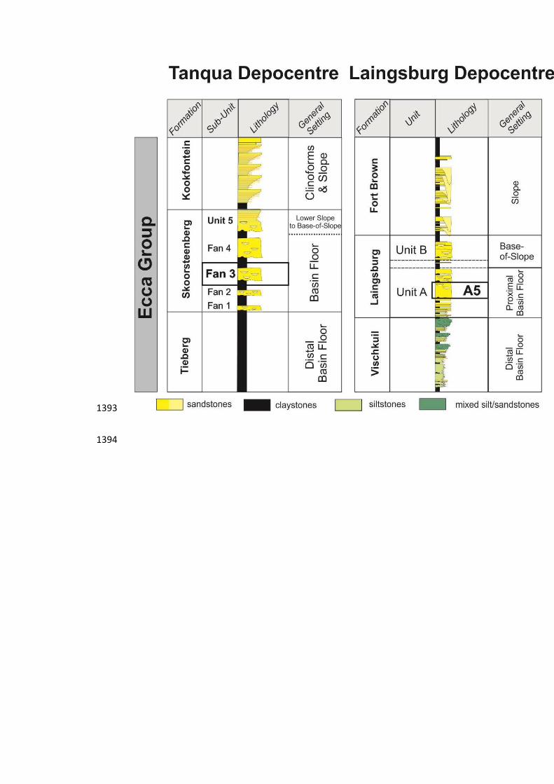
1393
1394

1395
1396

1397
1398

1399

1400

1401
1402
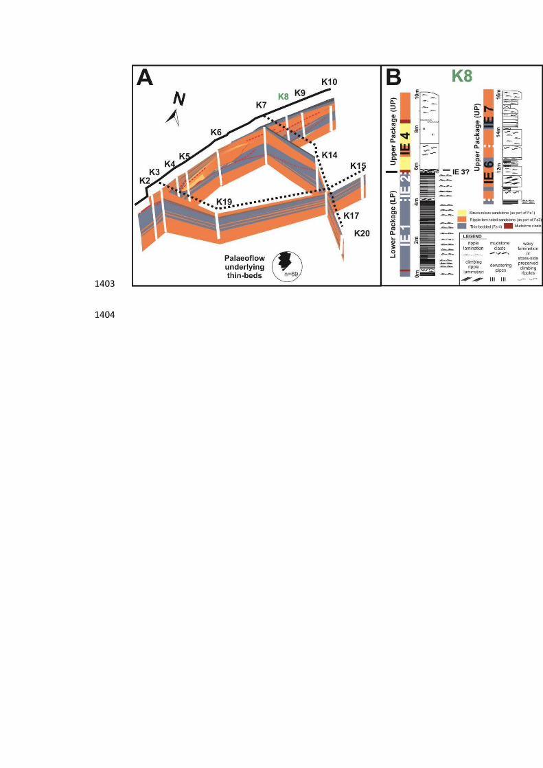
1403
1404

1405
1406

1407
1408

1409
1410
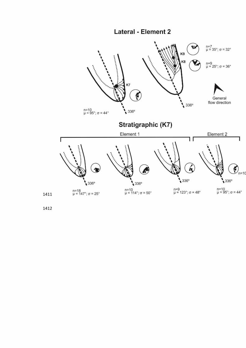
1411
1412
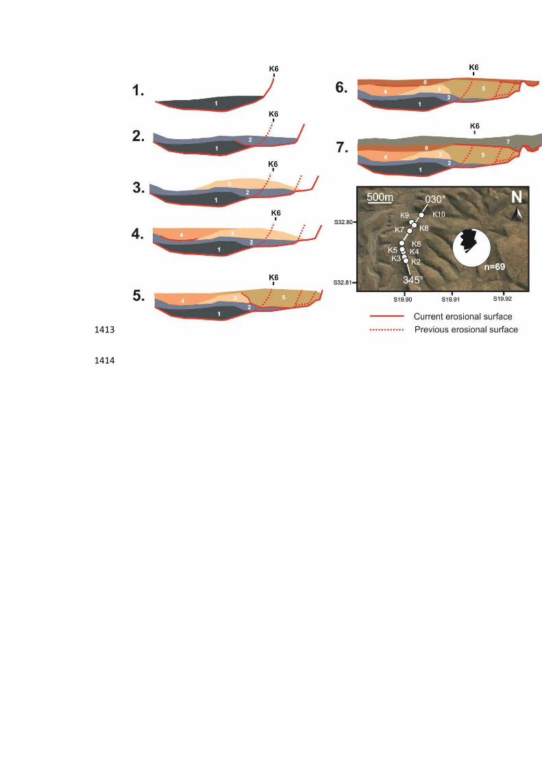
1413
1414

1415
1416

1417
1418