giant spider construction
TRANSCRIPT
O
btaine
d Fro
m
Omarsh
aunte
dtrail
.com
HauntMaven.com - Wolfstone's Haunted Halloween Site
http://wolfstone.halloweenhost.com/HalloweenTech/spimak_SpiderConstruction.html
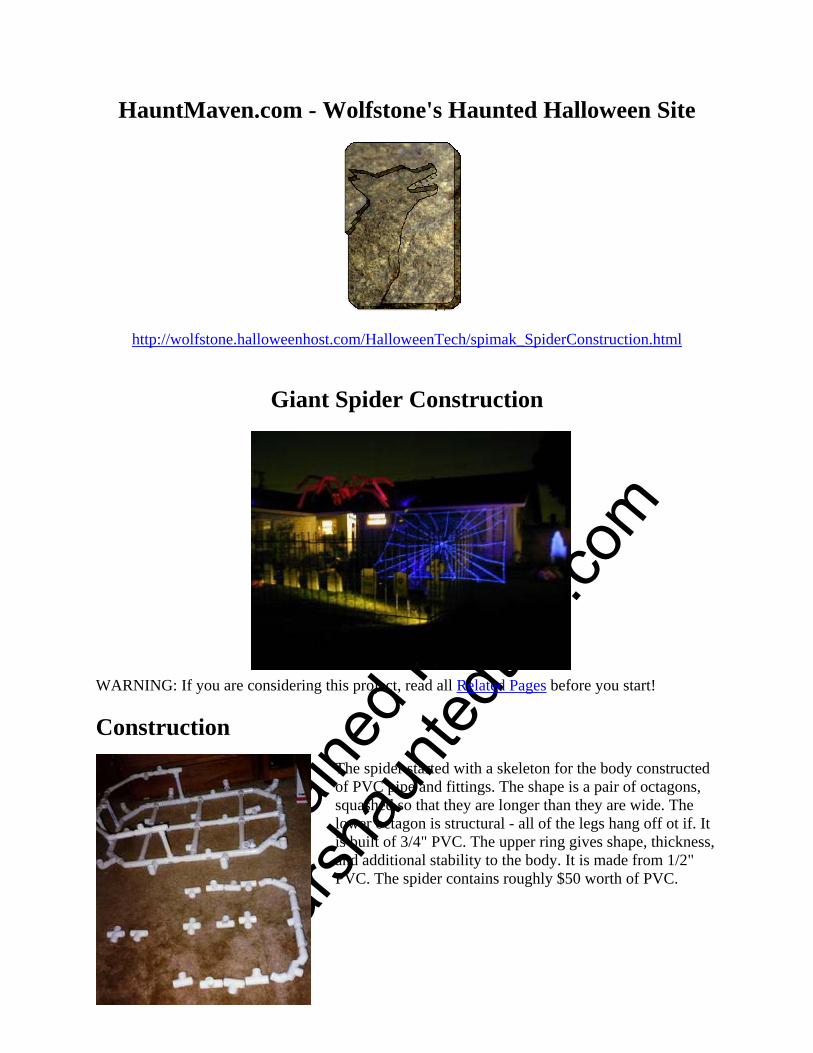
Giant Spider Construction
WARNING: If you are considering this project, read all Related Pages before you start!
Construction The spider started with a skeleton for the body constructed of PVC pipe and fittings. The shape is a pair of octagons, squashed so that they are longer than they are wide. The lower octagon is structural - all of the legs hang off ot if. It is built of 3/4" PVC. The upper ring gives shape, thickness, and additional stability to the body. It is made from 1/2" PVC. The spider contains roughly $50 worth of PVC.

O
btaine
d Fro
m
Omarsh
aunte
dtrail
.com
All of the parts are dry‐fit. Only after everything is known to fit together properly is PVC cement used to permanently assemble the spider skeleton. The body will be glued up into a single unit. The legs are pinned into place, and can be removed and broken down for storage.
The builders pose with the spider's skeletal body. Only the two front legs are installed, making them look more like antennae. The fellow in blue is David, Chief Architect of The Spider Project. The white bundle behind him consists of the additional PVC pipes that form the rest of the legs.
The spider is animated, because the only thing more terrifying than a giant spider is a giant spider lunging at you! The body is made to rock back and forth on a central pivot. Up front is an air cylinder that provides the motion. Although there is only one air cylinder in the spider, the rocking of the body causes all of the legs to move. When the spider lunges down at the victims, the front legs wave up and down.
The compressor in the photo is a small unit used only for testing.
The air cylinder is made from a screen door closer. This clever trick has been used for years by budget imagineers.
Also visible is the Haunt Air Manager (HAM) unit, consisting of air tank, pressure regulator, solenoid valve, and exhaust valve.
O
btaine
d Fro
m
Omarsh
aunte
dtrail
.com
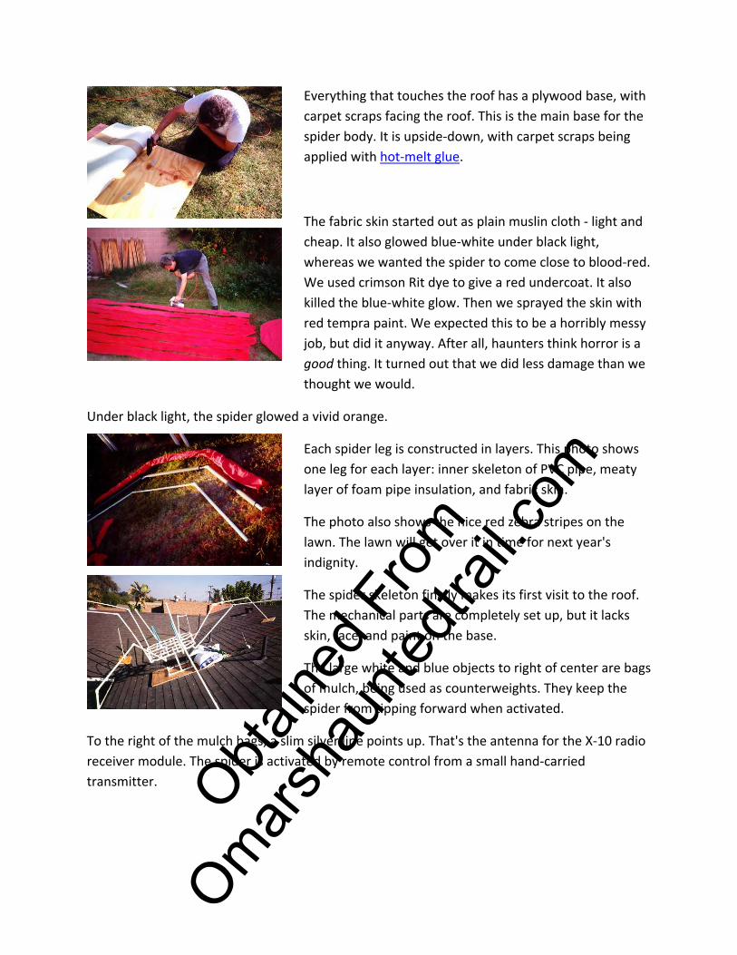
Everything that touches the roof has a plywood base, with carpet scraps facing the roof. This is the main base for the spider body. It is upside‐down, with carpet scraps being applied with hot‐melt glue.
The fabric skin started out as plain muslin cloth ‐ light and cheap. It also glowed blue‐white under black light, whereas we wanted the spider to come close to blood‐red. We used crimson Rit dye to give a red undercoat. It also killed the blue‐white glow. Then we sprayed the skin with red tempra paint. We expected this to be a horribly messy job, but did it anyway. After all, haunters think horror is a good thing. It turned out that we did less damage than we thought we would.
Under black light, the spider glowed a vivid orange.
Each spider leg is constructed in layers. This photo shows one leg for each layer: inner skeleton of PVC pipe, meaty layer of foam pipe insulation, and fabric skin.
The photo also shows the nice red zebra stripes on the lawn. The lawn will get over it in time for next year's indignity.
The spider skeleton finally makes its first visit to the roof. The mechanical parts are completely set up, but it lacks skin, face, and paint on the base.
The large white and blue objects to right of center are bags of mulch, being used as counterweights. They keep the spider from tipping forward when activated.
To the right of the mulch bags, a slim silver line points up. That's the antenna for the X‐10 radio receiver module. The spider is activated by remote control from a small hand‐carried transmitter.

O
btaine
d Fro
m
Omarsh
aunte
dtrail
.com
Six of the spider's feet touch the roof. Those legs don't need to be terribly strong, because they are supported at both ends. This is a foot pad, which anchors the far end of the legs.
The pad is plywood, with carpet scraps glued to the back. The PVC pipe of the leg catches on a bolt, projecting up through the plywood. A small bungie cord holds the leg down to the plywood pad.
With a little black paint, the foot pad will be invisible on the roof.
Once on the roof, the spider undergoes dynamic testing: the air cylinder is actuated to make the spider rear up and drop down. Down below, David judges the effectiveness and offers advice, such as "Not threatening enough! Move his left leg a little closer to the porch!"
Note that the two front legs reach out over the edge of the roof ‐ towards the Trick‐Or‐Treaters. Since these legs are only supported on one end, they are constructed to be light at the hanging end, and well‐anchored at the body end.
Here is Master Haunter Dennis, posing with the spider to give you an idea of how big that thing really is. It might help to know that each leg is 10 feet long!
The spider was given a pair of eyes, made from faceted plastic "gems". Behind each gem was a pile of self‐flashing LEDs, some yellow, some green. When activated, the LEDs twinkled, casting light through various facets.
The overall effect was a glowing, twinkling, moving kind of thing.
O
btaine
d Fro
m
Omarsh
aunte
dtrail
.com
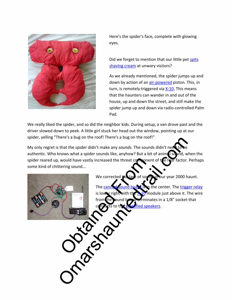
Here's the spider's face, complete with glowing eyes.
Did we forget to mention that our little pet spits shaving cream at unwary visitors?
As we already mentioned, the spider jumps up and down by action of an air‐powered piston. This, in turn, is remotely triggered via X‐10. This means that the haunters can wander in and out of the house, up and down the street, and still make the spider jump up and down via radio‐controlled Palm Pad.
We really liked the spider, and so did the neighbor kids. During setup, a van drove past and the driver slowed down to peek. A little girl stuck her head out the window, pointing up at our spider, yelling "There's a bug on the roof! There's a bug on the roof!"
My only regret is that the spider didn't make any sounds. The sounds didn't need to be authentic. Who knows what a spider sounds like, anyhow? But a bit of animal sound, when the spider reared up, would have vastly increased the threat component of the fear factor. Perhaps some kind of chittering sound...
We corrected the lack of sound in our year 2000 haunt.
The canned sound board is in the center. The trigger relay is lower right with the X‐10 module just above it. The wire from the sound board terminates in a 1/8" socket that connects to the amplified speakers.
O
btaine
d fro
m
Omarsh
aunte
dtrail
.com
Did we forget to mention that our little pet spits shaving cream at unwary visitors?
Spider Spitter
Mechanism Did we forget to mention that our little pet spits shaving cream at unwary visitors? We actually had two of these. The one on the small tripod attacked from the side. The other one was on the roof, near the front of the spider.
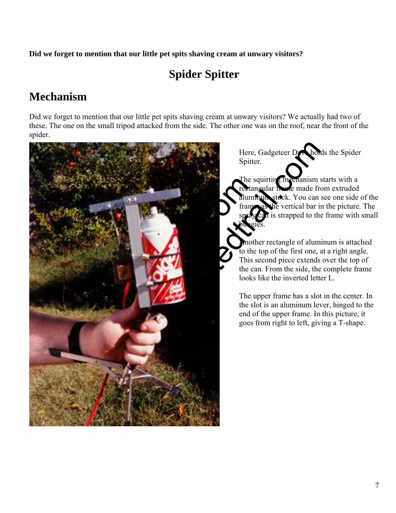
Here, Gadgeteer Dave holds the Spider Spitter.
7
The squirting mechanism starts with a rectangular frame made from extruded aluminum stock. You can see one side of the frame, as the vertical bar in the picture. The spray can is strapped to the frame with small bungies.
Another rectangle of aluminum is attached to the top of the first one, at a right angle. This second piece extends over the top of the can. From the side, the complete frame looks like the inverted letter L.
The upper frame has a slot in the center. In the slot is an aluminum lever, hinged to the end of the upper frame. In this picture, it goes from right to left, giving a T-shape.
O
btaine
d fro
m
Omarsh
aunte
dtrail
.com
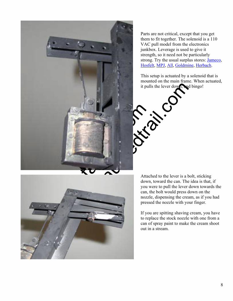
Parts are not critical, except that you get them to fit together. The solenoid is a 110 VAC pull model from the electronics junkbox. Leverage is used to give it strength, so it need not be particularly strong. Try the usual surplus stores: Jameco, Hosfelt, MPJ, All, Goldmine, Herbach.
This setup is actuated by a solenoid that is mounted on the main frame. When actuated, it pulls the lever down, and bingo!
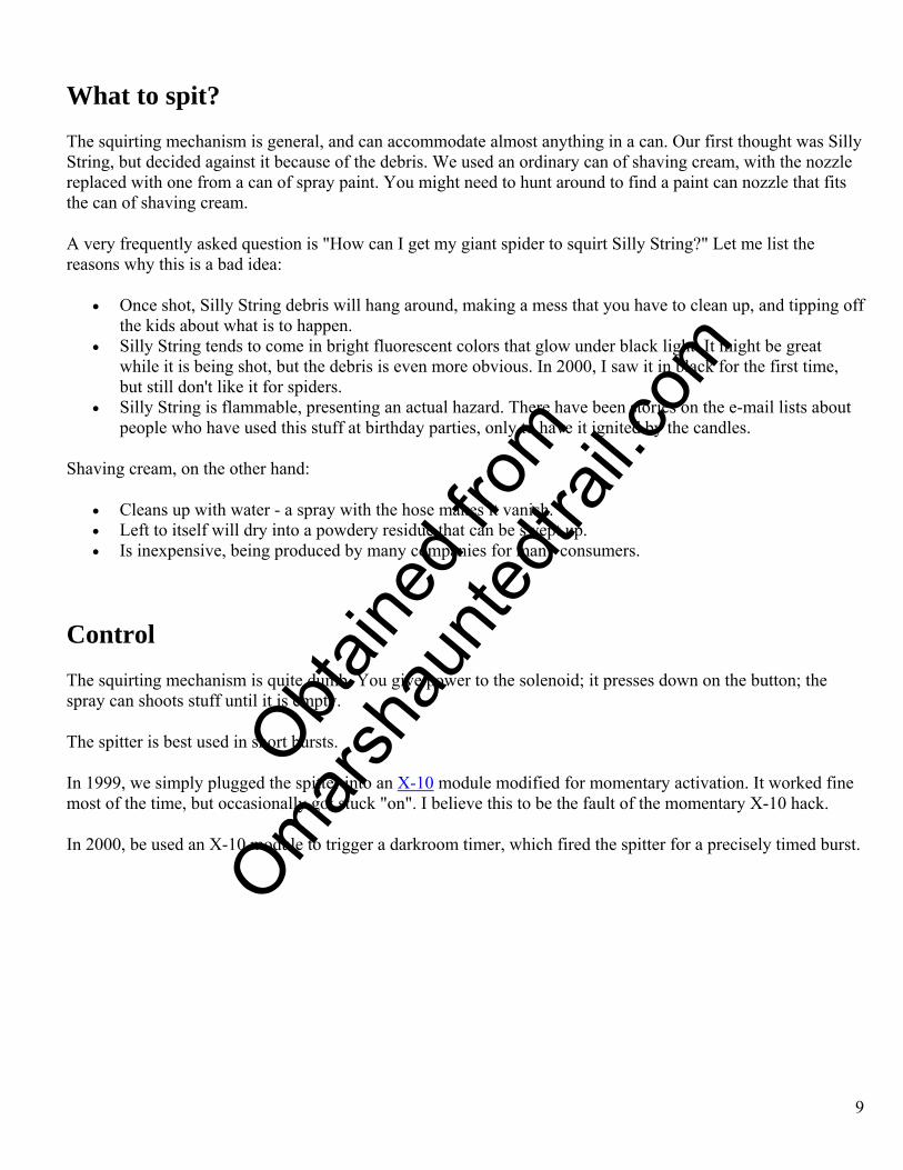
Attached to the lever is a bolt, sticking down, toward the can. The idea is that, if you were to pull the lever down towards the can, the bolt would press down on the nozzle, dispensing the cream, as if you had pressed the nozzle with your finger.
8
If you are spitting shaving cream, you have to replace the stock nozzle with one from a can of spray paint to make the cream shoot out in a stream.
O
btaine
d fro
m
Omarsh
aunte
dtrail
.com
9
What to spit? The squirting mechanism is general, and can accommodate almost anything in a can. Our first thought was Silly String, but decided against it because of the debris. We used an ordinary can of shaving cream, with the nozzle replaced with one from a can of spray paint. You might need to hunt around to find a paint can nozzle that fits the can of shaving cream.
A very frequently asked question is "How can I get my giant spider to squirt Silly String?" Let me list the reasons why this is a bad idea:
• Once shot, Silly String debris will hang around, making a mess that you have to clean up, and tipping off the kids about what is to happen.
• Silly String tends to come in bright fluorescent colors that glow under black light. It might be great while it is being shot, but the debris is even more obvious. In 2000, I saw it in black for the first time, but still don't like it for spiders.
• Silly String is flammable, presenting an actual hazard. There have been stories on the e-mail lists about people who have used this stuff at birthday parties, only to have it ignited by the candles.
Shaving cream, on the other hand:
• Cleans up with water - a spray with the hose makes it vanish. • Left to itself will dry into a powdery residue that can be swept up. • Is inexpensive, being produced by many companies for many consumers.
Control The squirting mechanism is quite dumb. You give power to the solenoid; it presses down on the button; the spray can shoots stuff until it is empty.
The spitter is best used in short bursts.
In 1999, we simply plugged the spitter into an X-10 module modified for momentary activation. It worked fine most of the time, but occasionally got stuck "on". I believe this to be the fault of the momentary X-10 hack.
In 2000, be used an X-10 module to trigger a darkroom timer, which fired the spitter for a precisely timed burst.
O
btaine
d fro
m
Omarsh
aunte
dtrail
.com
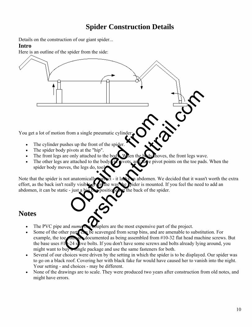
Spider Construction Details Details on the construction of our giant spider... Intro Here is an outline of the spider from the side:
You get a lot of motion from a single pneumatic cylinder:
• The cylinder pushes up the front of the spider. • The spider body pivots at the "hip". • The front legs are only attached to the body. When the body moves, the front legs wave. • The other legs are attached to the body via pivots, and have pivot points on the toe pads. When the
spider body moves, the legs do, too!
Note that the spider is not anatomically correct - it lacks an abdomen. We decided that it wasn't worth the extra effort, as the back isn't really visible given the way the spider is mounted. If you feel the need to add an abdomen, it can be static - just a big bag positioned at the back of the spider.
Notes • The PVC pipe and numerous couplers are the most expensive part of the project. • Some of the other parts can be scavenged from scrap bins, and are amenable to substitution. For
example, the toe pads are documented as being assembled from #10-32 flat head machine screws. But the base uses #10-24 stove bolts. If you don't have some screws and bolts already lying around, you might want to buy a single package and use the same fasteners for both.
• Several of our choices were driven by the setting in which the spider is to be displayed. Our spider was to go on a black roof. Covering her with black fake fur would have caused her to vanish into the night. Your setting - and choices - may be different.
• None of the drawings are to scale. They were produced two years after construction from old notes, and might have errors.
10
O
btaine
d fro
m
Omarsh
aunte
dtrail
.com
CAUTIONS • We aren't mechanical engineers. We built something that seems to work well for us, but might not work
for you. We are merely documenting what we did. Use your own judgement in building something like this.
• The animated spider throws a lot of weight around, and might not be stable on your roof if the pitch is steep. In our situation, she was solid when reared up, but in the relaxed position showed a slight tendency to tip forwards. We solved this with a counterweight on the back of the base, consisting of a bag of mulch.
• Watch the weather! The spider skeleton won't be harmed by rain. The electronics and pneumatics can be protected from foul weather with a bit of work. The biggest rain worry that we have is that the fabric covering will absorb water and get heavy. This will strain the skeleton in the areas that are marginally designed.
• Know your materials and tools; use them properly and safely.
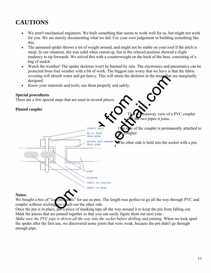
Special procedures There are a few special steps that are used in several places: Pinned coupler
This is a cutaway view of a PVC coupler and the two pipes it joins.
One side of the coupler is permanently attached to the coupler. The other side is held into the socket with a pin.
Notes: We bought a box of "concrete nails" for use as pins. The length was perfect to go all the way through PVC and coupler without sticking too much out the other side. Once the pin is in place, put a piece of masking tape all the way around it to keep the pin from falling out. Mark the pieces that are pinned together so that you can easily figure them out next year. Make sure the PVC pipe is driven all the way into the socket before drilling and pinning. When we took apart the spider after the first use, we discovered some joints that were weak, because the pin didn't go through enough pipe.
11

O
btaine
d fro
m
Omarsh
aunte
dtrail
.com
These are the nails we used for the pins.
Bored tee The standard PVC tee has a "shoulder" inside that keeps the pipe from being driven too deep into it. This is visible as the gray area in this cutaway view. In some cases, we need to run a single length of pipe all the way through a tee. Think of using the pipe as an axel, with the tee rotating on it. This requires that the material in gray be bored out.
Notes:
• This is probably something you can't do with a drill bit! • We used a small lathe. Ask friends and neighbors if they work with power tools as a hobby. • Reader Thanh Quach used a different method. "Instead of boring out a 3/4' tee, I just used a 1 inch tee
with step down sizers to connect to the legs."
12
O
btaine
d fro
m
Omarsh
aunte
dtrail
.com
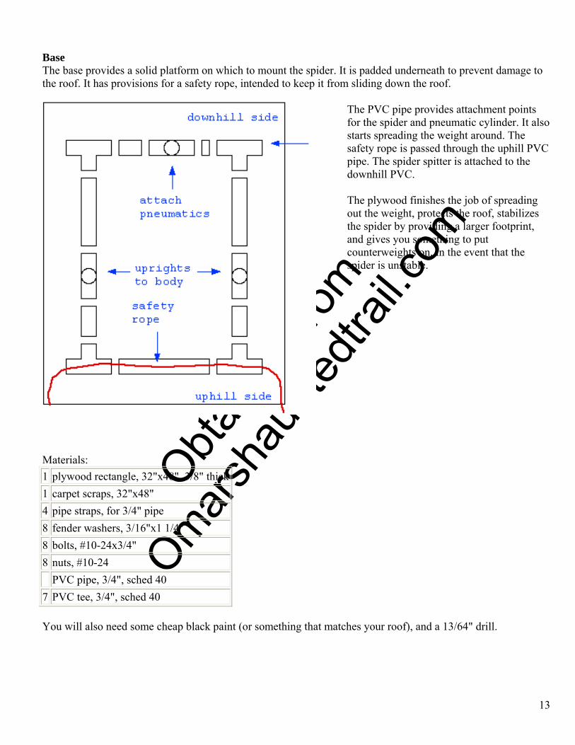
Base The base provides a solid platform on which to mount the spider. It is padded underneath to prevent damage to the roof. It has provisions for a safety rope, intended to keep it from sliding down the roof.
The PVC pipe provides attachment points for the spider and pneumatic cylinder. It also starts spreading the weight around. The safety rope is passed through the uphill PVC pipe. The spider spitter is attached to the downhill PVC.
The plywood finishes the job of spreading out the weight, protects the roof, stabilizes the spider by providing a larger footprint, and gives you something to put counterweights on, in the event that the spider is unstable.
Materials: 1 plywood rectangle, 32"x48", 3/8" thick 1 carpet scraps, 32"x48" 4 pipe straps, for 3/4" pipe 8 fender washers, 3/16"x1 1/4" 8 bolts, #10-24x3/4" 8 nuts, #10-24 PVC pipe, 3/4", sched 40 7 PVC tee, 3/4", sched 40 You will also need some cheap black paint (or something that matches your roof), and a 13/64" drill.
13
O
btaine
d fro
m
Omarsh
aunte
dtrail
.com
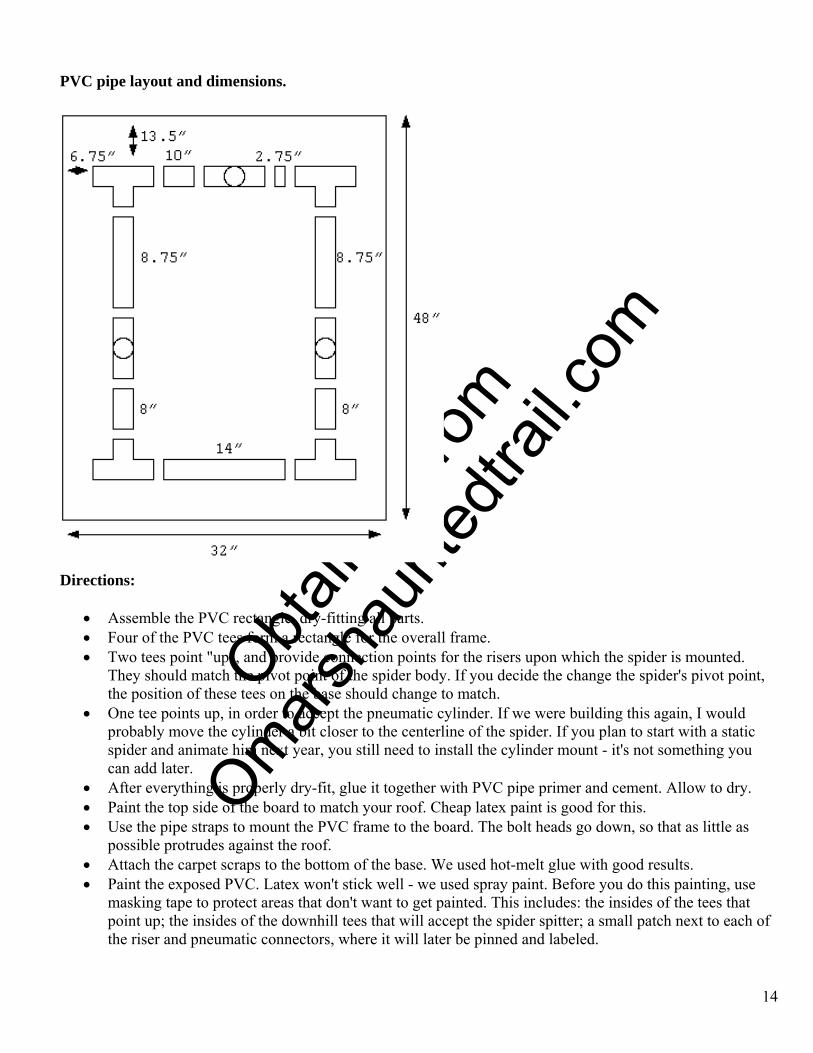
PVC pipe layout and dimensions.
Directions:
• Assemble the PVC rectangle, dry-fitting all parts. • Four of the PVC tees form a rectangle for the overall frame. • Two tees point "up", and provide connection points for the risers upon which the spider is mounted.
They should match the pivot point of the spider body. If you decide the change the spider's pivot point, the position of these tees on the base should change to match.
• One tee points up, in order to accept the pneumatic cylinder. If we were building this again, I would probably move the cylinder a bit closer to the centerline of the spider. If you plan to start with a static spider and animate him next year, you still need to install the cylinder mount - it's not something you can add later.
• After everything is properly dry-fit, glue it together with PVC pipe primer and cement. Allow to dry. • Paint the top side of the board to match your roof. Cheap latex paint is good for this. • Use the pipe straps to mount the PVC frame to the board. The bolt heads go down, so that as little as
possible protrudes against the roof. • Attach the carpet scraps to the bottom of the base. We used hot-melt glue with good results. • Paint the exposed PVC. Latex won't stick well - we used spray paint. Before you do this painting, use
masking tape to protect areas that don't want to get painted. This includes: the insides of the tees that point up; the insides of the downhill tees that will accept the spider spitter; a small patch next to each of the riser and pneumatic connectors, where it will later be pinned and labeled.
14
O
btaine
d fro
m
Omarsh
aunte
dtrail
.com
Body The body is composed of:
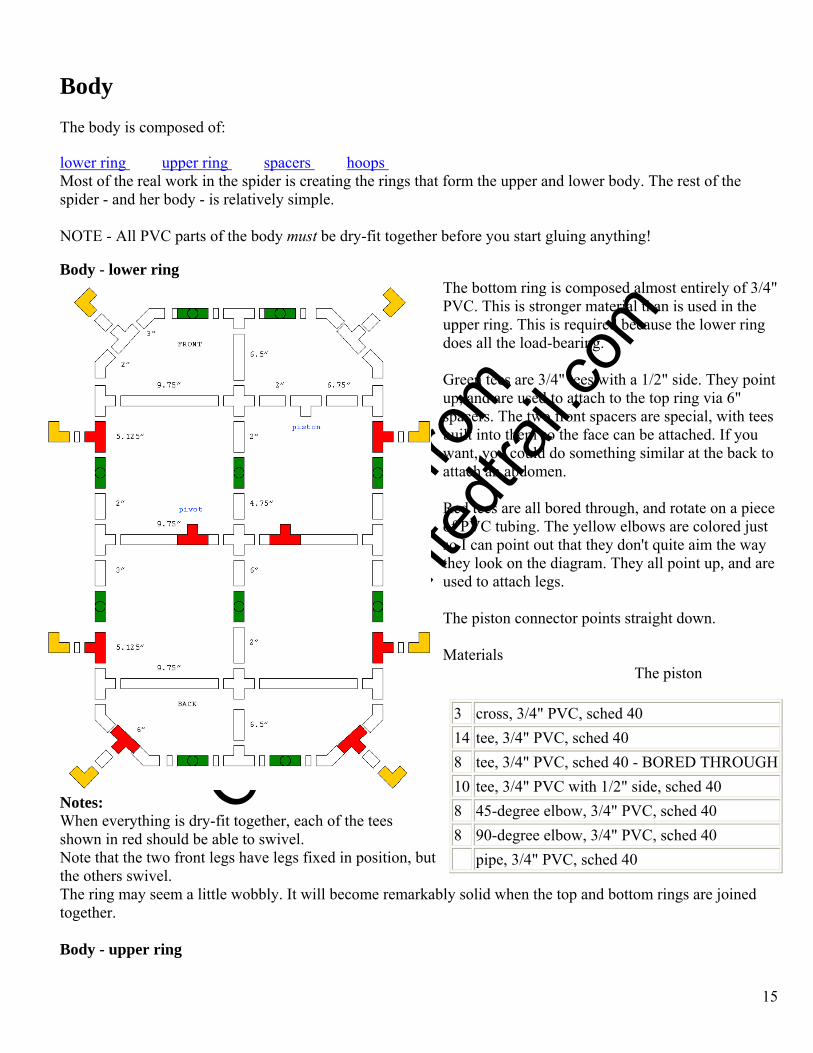
lower ring upper ring spacers hoops Most of the real work in the spider is creating the rings that form the upper and lower body. The rest of the spider - and her body - is relatively simple. NOTE - All PVC parts of the body must be dry-fit together before you start gluing anything! Body - lower ring
The bottom ring is composed almost entirely of 3/4" PVC. This is stronger material than is used in the upper ring. This is required because the lower ring does all the load-bearing.
15
Green tees are 3/4" tees with a 1/2" side. They point up, and are used to attach to the top ring via 6" spacers. The two front spacers are special, with tees built into them so the face can be attached. If you want, you could do something similar at the back to attach an abdomen. Red tees are all bored through, and rotate on a piece of PVC tubing. The yellow elbows are colored just so I can point out that they don't quite aim the way they look on the diagram. They all point up, and are used to attach legs.
Materials: The piston connector points straight down. Materials
The piston
3 cross, 3/4" PVC, sched 40
Notes: When everything is dry-fit together, each of the tees shown in red should be able to swivel. Note that the two front legs have legs fixed in position, but the others swivel. The ring may seem a little wobbly. It will become remarkably solid when the top and bottom rings are joined together. Body - upper ring
14 tee, 3/4" PVC, sched 40 8 tee, 3/4" PVC, sched 40 - BORED THROUGH10 tee, 3/4" PVC with 1/2" side, sched 40 8 45-degree elbow, 3/4" PVC, sched 40 8 90-degree elbow, 3/4" PVC, sched 40 pipe, 3/4" PVC, sched 40
O
btaine
d fro
m
Omarsh
aunte
dtrail
.com
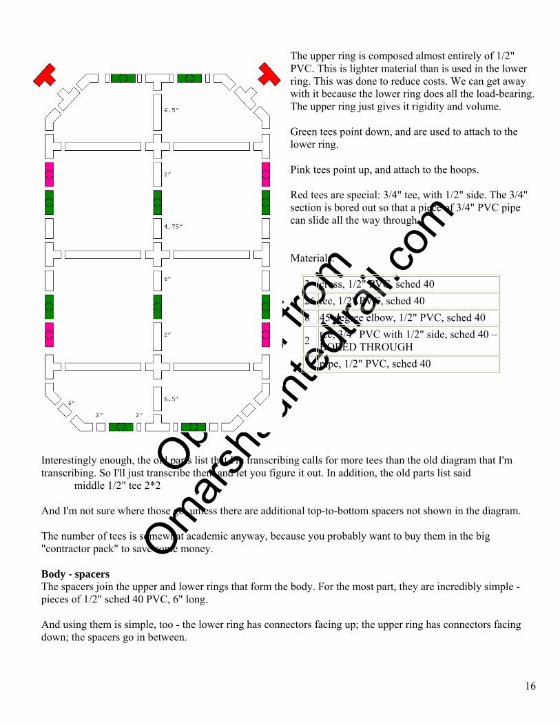
The upper ring is composed almost entirely of 1/2" PVC. This is lighter material than is used in the lower ring. This was done to reduce costs. We can get away with it because the lower ring does all the load-bearing. The upper ring just gives it rigidity and volume. Green tees point down, and are used to attach to the lower ring. Pink tees point up, and attach to the hoops. Red tees are special: 3/4" tee, with 1/2" side. The 3/4" section is bored out so that a piece of 3/4" PVC pipe can slide all the way through. Materials:
3 cross, 1/2" PVC, sched 40 26 tee, 1/2" PVC, sched 40 8 45-degree elbow, 1/2" PVC, sched 40
2 tee, 3/4" PVC with 1/2" side, sched 40 –BORED THROUGH
pipe, 1/2" PVC, sched 40
Interestingly enough, the old parts list that I'm transcribing calls for more tees than the old diagram that I'm transcribing. So I'll just transcribe them and let you figure it out. In addition, the old parts list said
middle 1/2" tee 2*2 And I'm not sure where those go, unless there are additional top-to-bottom spacers not shown in the diagram. The number of tees is somewhat academic anyway, because you probably want to buy them in the big "contractor pack" to save some money. Body - spacers The spacers join the upper and lower rings that form the body. For the most part, they are incredibly simple - pieces of 1/2" sched 40 PVC, 6" long. And using them is simple, too - the lower ring has connectors facing up; the upper ring has connectors facing down; the spacers go in between.
16
O
btaine
d fro
m
Omarsh
aunte
dtrail
.com
There is a minor exception to the simplicity of the spacers: two of the spacers are lengths of 1/2" PVC with a tee near the middle. [We actually used a 2" and a 3" piece with the tee between.] The overall length is still 6". These special spacers go in the front of the spider, and are used to attach the face. If I count them right, we need 8 regular spacers, and 2 of the specials. Body - hoops The upper and lower body rings provide structure, strength, and volume. But if we stopped here, the spider body would be more of a geometric shape than an organic thing. We need to round it out a little ... and do so inexpensively. We chose to have a pair of semicircular "hoops" arcing over the spider, from side to side. When covered by a fabric "skin", the spider looks much larger and more organic. But if you look too close, it has somewhat of a "covered wagon" effect - especially from the side. You could solve this with more hoops; a layer over the hoops to support the cloth; or more rigid and/or textured body. We chose to limit the view of the spider to the front - where it looks very good. The hoops are formed by cutting a "Hula Hoop" in half. Legs Our giant spider has two slightly different kinds of legs:
front and others All the legs, no matter what type, are composed of three sections of PVC pipe, each piece approximately 3.3 feet long, being 1/3 of a 10' stick of PVC. So, each leg totals 10 feet in length. Although long and bulky in operation, the legs store easily in sections. We mark every leg part with a two-character designation. A legger indicates which leg, and a number tells which joint in the leg. We mark both sides of a joint to make sure that we know how everything goes together next year.
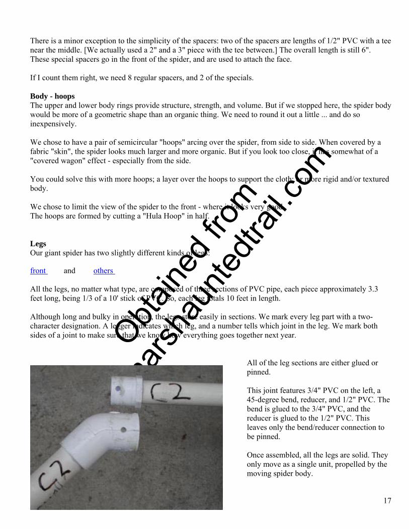
All of the leg sections are either glued or pinned.
This joint features 3/4" PVC on the left, a 45-degree bend, reducer, and 1/2" PVC. The bend is glued to the 3/4" PVC, and the reducer is glued to the 1/2" PVC. This leaves only the bend/reducer connection to be pinned. Once assembled, all the legs are solid. They only move as a single unit, propelled by the moving spider body.
17
O
btaine
d fro
m
Omarsh
aunte
dtrail
.com
18
Legs - front The front legs are supported only where they connect to the body. In use, they project out over the edge of the roof, reaching out at visitors. It is important to make them strong enough to be support their full span by holding one end, and lighter out towards the unsupported end. The leg section nearest the body is 3/4" PVC. The outer sections are 1/2" PVC. The front legs use 45-degree bends everywhere. Their setup is:
• body coupling | 3/4" pipe | 45-degree | reducer | 1/2" pipe | 45-degree | 1/2" pipe The reducer is glued on to the 1/2" pipe. Each bend is glued to one piece of pipe. This yields the following three assemblies per leg:
• 3/4" pipe | 45-degree • reducer | 1/2" pipe • 45-degree | 1/2" pipe
To use, these three assemblies are tightly pushed together, drilled, and pinned. Legs - others The other legs are similar in construction to the front legs, except:
• Use a mix of 90-degree bends and 45, in order to get some random leg positions. • Are supported at both ends (spider body and toe pad).
This yields the following three assemblies per leg:
• 3/4" pipe | 45-degree (or maybe 90) • reducer | 1/2" pipe • 45-degree (or maybe 90) | 1/2" pipe
To use, these three assemblies are tightly pushed together, drilled, and pinned. Toe pads Each spider leg that touches the roof does so through a "toe pad". This provides protection for the roof and gives the leg a pivot point. Materials: 1 plywood rectangle, 12"x12", 3/8" thick 1 carpet scraps, 12"x12" 1 machine screw, flat head, #10-32x1 1/4 1 nut, #10-32 1 S-hook, 1" 1 cut washer, 1/4" 1 lock washer, #10 1 fender washer, 1/4"x1 1/4" 1 bungie cord, small
O
btaine
d fro
m
Omarsh
aunte
dtrail
.com
You will also need some cheap black paint (or something that matches your roof), and a 13/64" drill. Directions:
• Dang! That's a lot of washers! Did we really use all of those? • Start by drilling a hole in the middle of the plywood. • Put the fender washer on the machine screw and put it through the hole. • Using a pair of pliars, squeeze the S-hook on each side, closing up the ends. It's now more of a figure 8. • Then start adding other things on the protruding end of the screw: cut washer; S-hook; lock washer; nut. • Tighten down this mess and put a dab of thread-lock on it. • Bend the S hook up from the board a little. Put the bungie on it. Crimp that end of the bungie so it won't
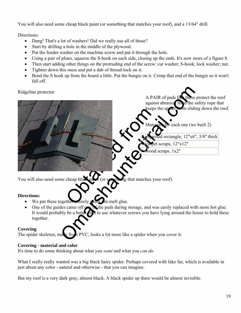
fall off. Ridgeline protector
A PAIR of pads like these protect the roof against abrasion from the safety rope that keeps the spider from sliding down the roof.
19
Materials for each one (we built 2) plywood rectangle, 12"x6", 3/8" thick
Materials fo r each one (we built two):
2
You will also need some cheap black paint (or something that matches your roof). Directions:
• We put these together entirely using hot-melt glue. • One of the guides came off one of the pads during storage, and was easily replaced with more hot glue.
It would probably be a better idea to use whatever screws you have lying around the house to hold these together.
Covering The spider skeleton, made from PVC, looks a lot more like a spider when you cover it: Covering - material and color It's time to do some thinking about what you want and what you can do. What I really really wanted was a big black hairy spider. Perhaps covered with fake fur, which is available in just about any color - natural and otherwise - that you can imagine. But my roof is a very dark gray, almost black. A black spider up there would be almost invisible.
1 carpet scraps, 12"x12" wood scraps, 1x2"
O
btaine
d fro
m
Omarsh
aunte
dtrail
.com
20
Dave wanted a blood-red spider, so we did that instead. We still could have used fake fur, and doing so would have given the spider a texture that hides wrinkles and structural elements like the hoops on the top of the body. But fake fur can be expensive. We settled on $.99/yard muslin, dyed in scarlet RIT fabric dye. The red spider is quite impressive, and brightly colored spiders can be found in nature. But sometimes I still wish he could have been black. If I reroof with something lighter, I can always recover the spider. You should also consider how the spider is to be lit. We wanted that spider to glow red. Naturally, this brings to mind black light. The muslin, from the store, glowed under black light with the standard blue/white of optical brighteners. The scarlet RIT didn't glow under black light. We intended the scarlet dye to do two things: kill some of the blue/white glow; and make the spider red. Then we planned a top-coat of a paint that did have a red glow. The scarlet dye was much more effective than we had planned. It killed every bit of glow. In retrospect, if we could have just killed some of the blue/white, that which remained might be colored by the scarlet dye. But we never had a chance to try that. The other problem, and we knew it going in, is that it is extremely difficult to find a paint or dye that glows an honest red under black light. Oh, there are plenty of glow paints that look red in normal light. Some are even marked "red", and sold as red fluorescent paint. But when the black light goes on, they glow orange. We wound up using a top-coat of a day-glow tempera paint mix. It looks very nice under white light, but certainly looks more orange under black light. Which brings up yet another topic - Don't use black light unless you have adjacent objects that you don't want to glow.Think about it for a minute. We put that spider on a nearly black roof. Even if we hit him with a halogen light, or a spotlight, the dark color and rough texture of the shingles would drink up any spilled light! Only the spider would be visible! The place to use black light is where you want to illuminate an object that is near other light colored objects or backgrounds, such as a Flying Crank Ghost in front of a red brick wall. In that case, use of a white light would illuminate ghost and red bricks, but black light would only pick up the fluorescent ghost. This is a cost-saving tip, because even the cheapest black light costs more than a white light. Covering - structure The spider is covered with a cloth bag. That's basically it. There are several pieces, each to suit a different part of the spider. But you can think of each as a cloth bag.
• body - This bag even has a drawstring sewn into the hem! Pulling on it tightens the bag around the PVC framework of the body and encloses all but a small area on the bottom, where the risers connect the body to the base.
• 6 legs - Just cylinders. • 2 front legs - Cylinders with one end sewn shut. • "face" - This is a bag with a roughly oval shape (more human than spider), with "fangs" sewn in.
Pneumatic assembly This isn't really a good place to go into the details of how to improvise a pneumatic cylinder from a screen door closer. (See below)
O
btaine
d fro
m
Omarsh
aunte
dtrail
.com
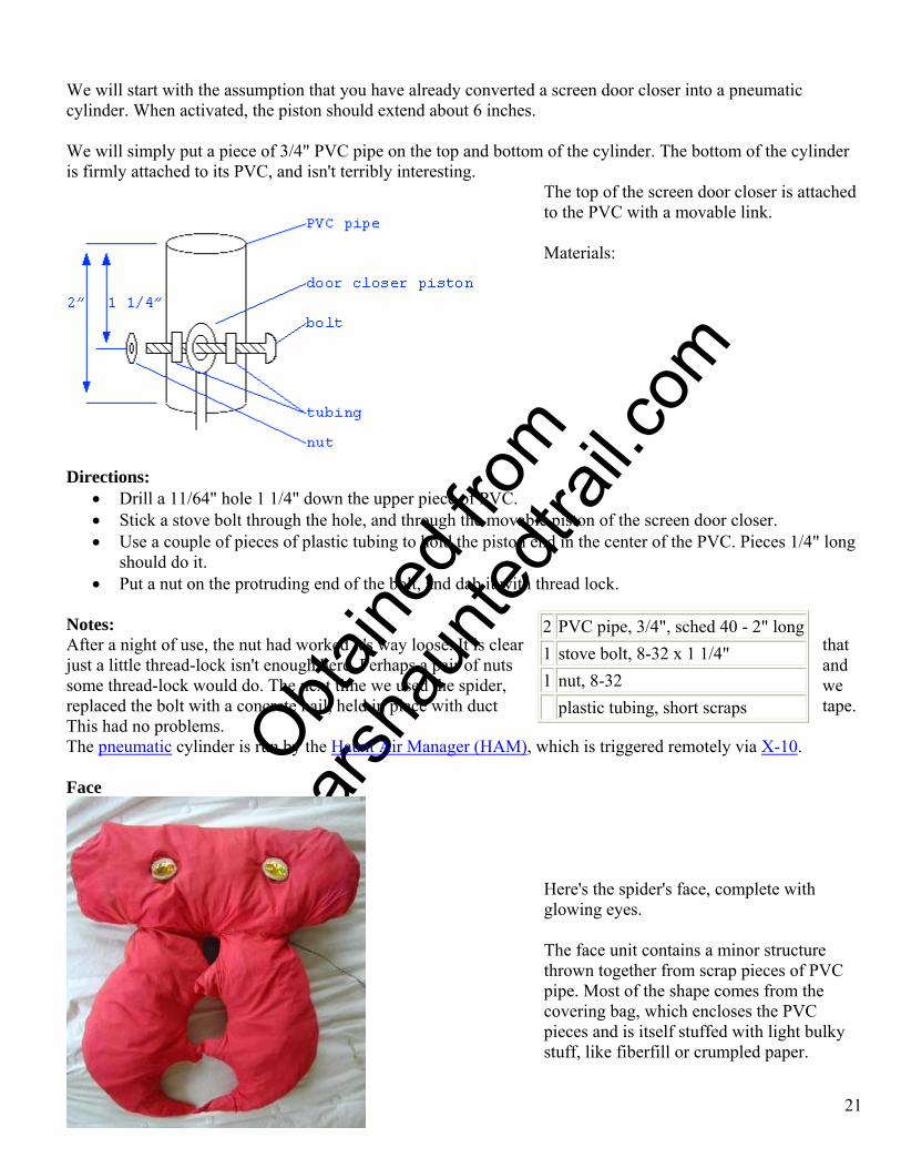
We will start with the assumption that you have already converted a screen door closer into a pneumatic cylinder. When activated, the piston should extend about 6 inches. We will simply put a piece of 3/4" PVC pipe on the top and bottom of the cylinder. The bottom of the cylinder is firmly attached to its PVC, and isn't terribly interesting.
The top of the screen door closer is attached to the PVC with a movable link.
21
Materials: Directions:
• Drill a 11/64" hole 1 1/4" down the upper piece of PVC. • Stick a stove bolt through the hole, and through the movable piston of the screen door closer. • Use a couple of pieces of plastic tubing to hold the piston end in the center of the PVC. Pieces 1/4" long
should do it. • Put a nut on the protruding end of the bolt, and dab it with thread lock.
Notes: After a night of use, the nut had worked it's way loose. It is clear that just a little thread-lock isn't enough here. Perhaps a pair of nuts and some thread-lock would do. The next time we used the spider, we replaced the bolt with a concrete nail, held in place with duct tape. This had no problems.
2 PVC pipe, 3/4", sched 40 - 2" long1 stove bolt, 8-32 x 1 1/4" 1 nut, 8-32 plastic tubing, short scraps
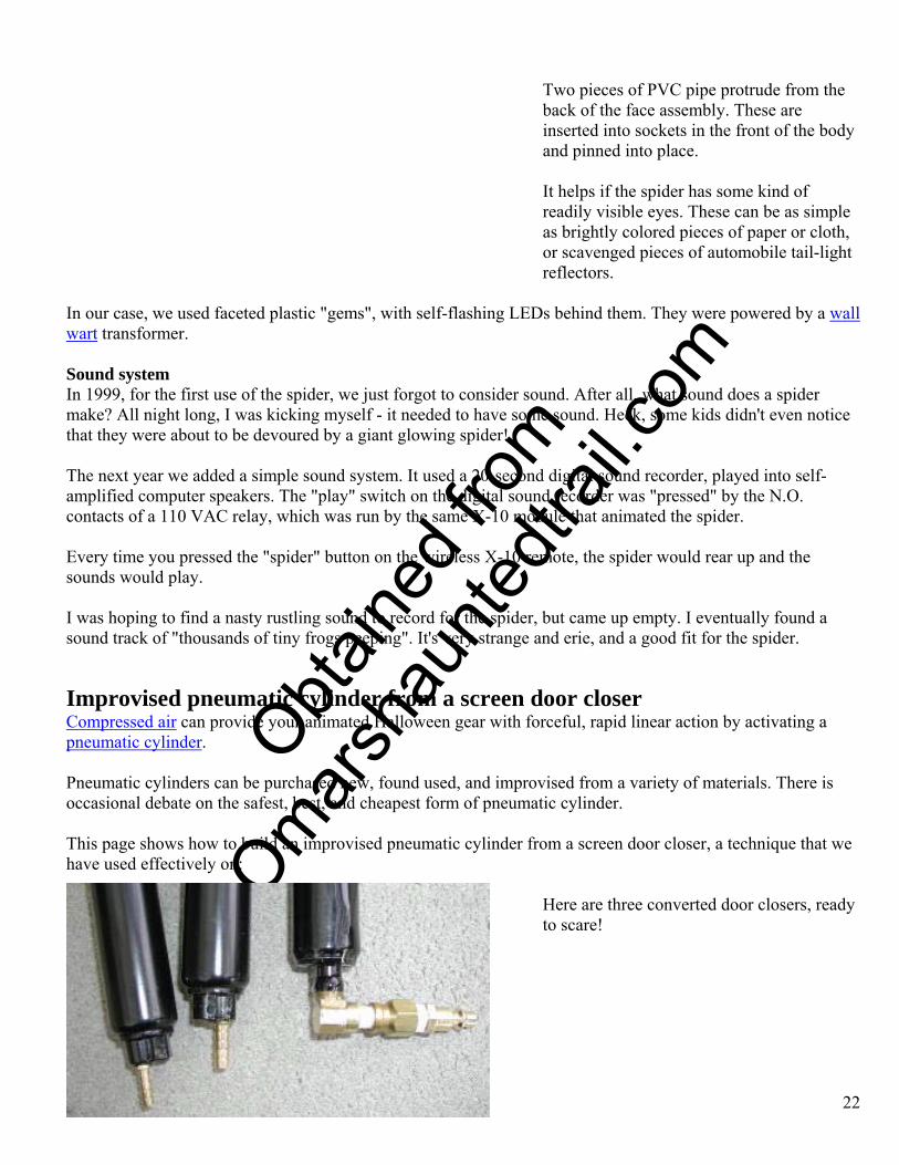
The pneumatic cylinder is run by the Haunt Air Manager (HAM), which is triggered remotely via X-10. Face
Here's the spider's face, complete with glowing eyes. The face unit contains a minor structure thrown together from scrap pieces of PVC pipe. Most of the shape comes from the covering bag, which encloses the PVC pieces and is itself stuffed with light bulky stuff, like fiberfill or crumpled paper.
O
btaine
d fro
m
Omarsh
aunte
dtrail
.com
Two pieces of PVC pipe protrude from the back of the face assembly. These are inserted into sockets in the front of the body and pinned into place.
It helps if the spider has some kind of readily visible eyes. These can be as simple as brightly colored pieces of paper or cloth, or scavenged pieces of automobile tail-light reflectors.
In our case, we used faceted plastic "gems", with self-flashing LEDs behind them. They were powered by a wall wart transformer. Sound system In 1999, for the first use of the spider, we just forgot to consider sound. After all, what sound does a spider make? All night long, I was kicking myself - it needed to have some sound. Heck, some kids didn't even notice that they were about to be devoured by a giant glowing spider! The next year we added a simple sound system. It used a 20-second digital sound recorder, played into self-amplified computer speakers. The "play" switch on the digital sound recorder was "pressed" by the N.O. contacts of a 110 VAC relay, which was run by the same X-10 module that animated the spider. Every time you pressed the "spider" button on the wireless X-10 remote, the spider would rear up and the sounds would play. I was hoping to find a nasty rustling sound to record for the spider, but came up empty. I eventually found a sound track of "thousands of tiny frogs peeping". It's very strange and erie, and a good fit for the spider.
Improvised pneumatic cylinder from a screen door closer Compressed air can provide your animated Halloween gear with forceful, rapid linear action by activating a pneumatic cylinder. Pneumatic cylinders can be purchased new, found used, and improvised from a variety of materials. There is occasional debate on the safest, best, and cheapest form of pneumatic cylinder. This page shows how to build an improvised pneumatic cylinder from a screen door closer, a technique that we have used effectively on:
22
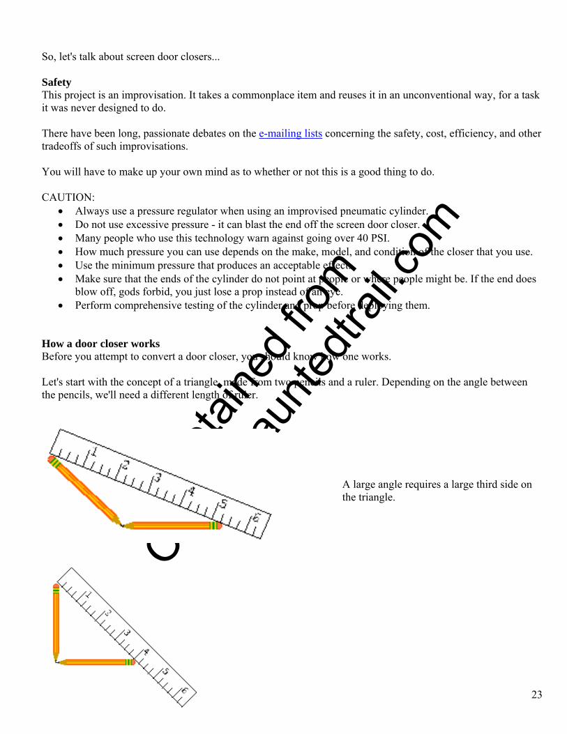
Here are three converted door closers, ready to scare!
O
btaine
d fro
m
Omarsh
aunte
dtrail
.com
So, let's talk about screen door closers... Safety This project is an improvisation. It takes a commonplace item and reuses it in an unconventional way, for a task it was never designed to do. There have been long, passionate debates on the e-mailing lists concerning the safety, cost, efficiency, and other tradeoffs of such improvisations. You will have to make up your own mind as to whether or not this is a good thing to do. CAUTION:
• Always use a pressure regulator when using an improvised pneumatic cylinder. • Do not use excessive pressure - it can blast the end off the screen door closer. • Many people who use this technology warn against going over 40 PSI. • How much pressure you can use depends on the make, model, and condition of the closer that you use. • Use the minimum pressure that produces an acceptable effect. • Make sure that the ends of the cylinder do not point at people or where people might be. If the end does
blow off, gods forbid, you just lose a prop instead of an eye. • Perform comprehensive testing of the cylinder and prop before deploying them.
How a door closer works Before you attempt to convert a door closer, you should know how one works. Let's start with the concept of a triangle, made from two pencils and a ruler. Depending on the angle between the pencils, we'll need a different length of ruler.
23
A large angle requires a large third side on the triangle.
O
btaine
d fro
m
Omarsh
aunte
dtrail
.com
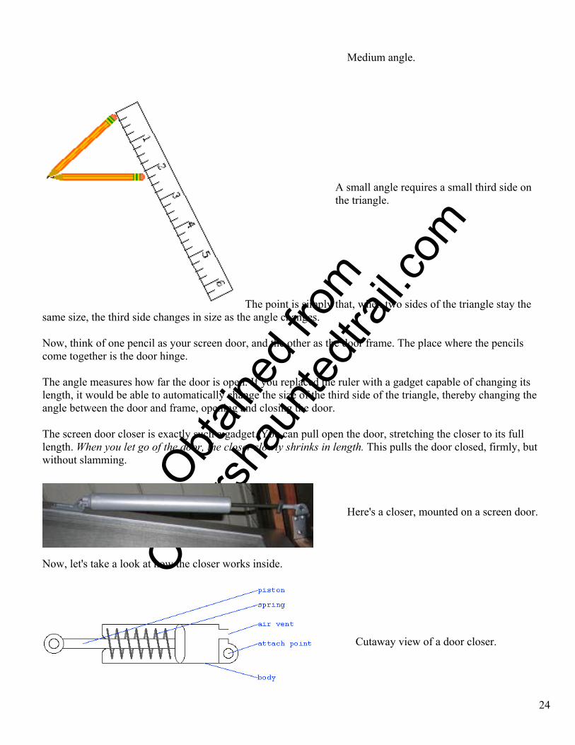
Medium angle.
A small angle requires a small third side on the triangle. The point is simply that, when two sides of the triangle stay the
same size, the third side changes in size as the angle changes. Now, think of one pencil as your screen door, and the other as the door frame. The place where the pencils come together is the door hinge. The angle measures how far the door is open. If you replaced the ruler with a gadget capable of changing its length, it would be able to automatically change the size of the third side of the triangle, thereby changing the angle between the door and frame, opening and closing the door. The screen door closer is exactly such a gadget. You can pull open the door, stretching the closer to its full length. When you let go of the door, the closer slowly shrinks in length. This pulls the door closed, firmly, but without slamming.
24
Here's a closer, mounted on a screen door.
Now, let's take a look at how the closer works inside.
Cutaway view of a door closer.
O
btaine
d fro
m
Omarsh
aunte
dtrail
.com
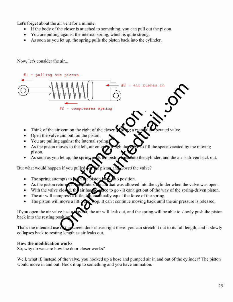
Let's forget about the air vent for a minute. • If the body of the closer is attached to something, you can pull out the piston. • You are pulling against the internal spring, which is quite strong. • As soon as you let up, the spring pulls the piston back into the cylinder.
Now, let's consider the air...
• Think of the air vent on the right of the closer as being a manually operated valve. • Open the valve and pull on the piston. • You are pulling against the internal spring. • As the piston moves to the left, air enters through the valve to fill the space vacated by the moving
piston. • As soon as you let up, the spring pulls the piston back into the cylinder, and the air is driven back out.
But what would happen if you pulled out the piston and closed the valve?
• The spring attempts to push the piston back into position. • As the piston returns, it encounters the air that was allowed into the cylinder when the valve was open. • With the valve closed, the air has no place to go - it can't get out of the way of the spring-driven piston. • The air will compress a little, but eventually equal the force of the spring. • The piston will move a little and stop. It can't continue moving back until the air pressure is released.
If you open the air valve just a tiny bit, the air will leak out, and the spring will be able to slowly push the piston back into the resting position. That's the intended use of the screen door closer right there: you can stretch it out to its full length, and it slowly collapses back to resting length as air leaks out. How the modification works So, why do we care how the door closer works? Well, what if, instead of the valve, you hooked up a hose and pumped air in and out of the cylinder? The piston would move in and out. Hook it up to something and you have animation.
25
O
btaine
d fro
m
Omarsh
aunte
dtrail
.com
And, to make it even simpler, most of these cylinders have an air valve in the form of a screw threaded into the body of the cylinder. If you unscrew that, you have a port into the cylinder, that can be used to pump air in and out. What is the result? After the conversion, you should have something that:
• operates on 30-40 PSI • has a reach of 6 inches • automatically retracts when air pressure is removed
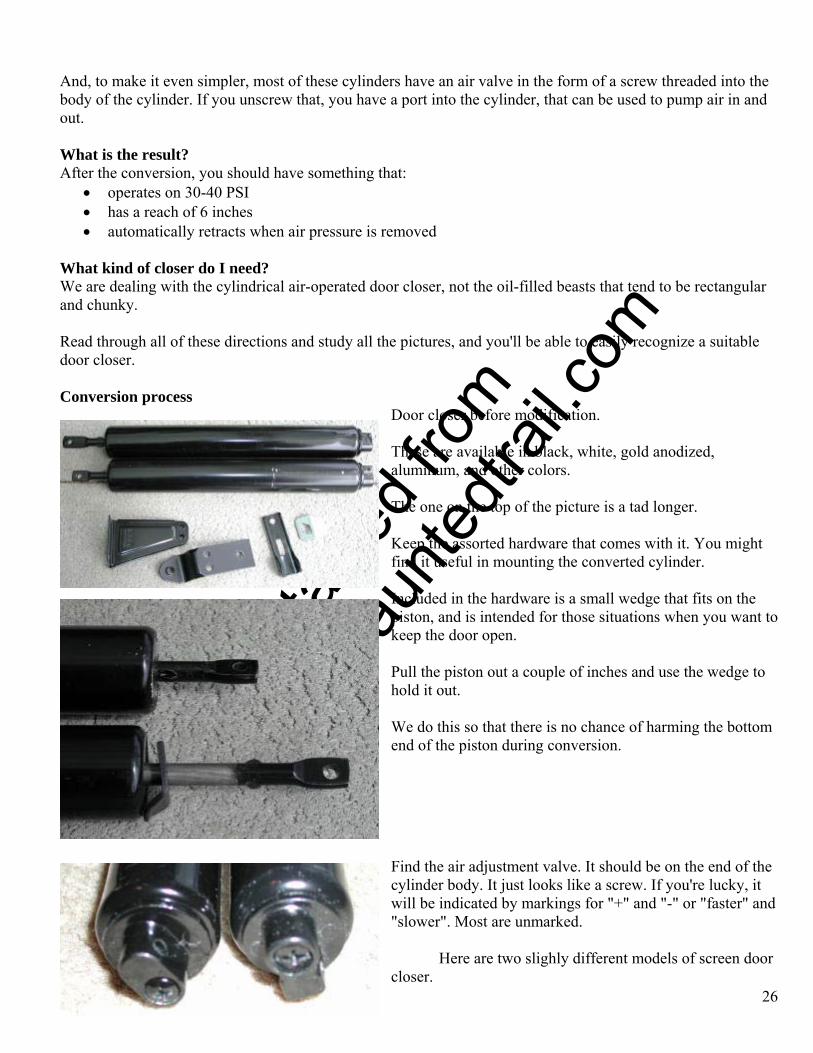
What kind of closer do I need? We are dealing with the cylindrical air-operated door closer, not the oil-filled beasts that tend to be rectangular and chunky. Read through all of these directions and study all the pictures, and you'll be able to easily recognize a suitable door closer. Conversion process
Door closer before modification.
These are available in black, white, gold anodized, aluminum, and other colors. The one on the top of the picture is a tad longer. Keep the assorted hardware that comes with it. You might find it useful in mounting the converted cylinder. Ip k
Ph
W ttom e
Here are two slighly different models of screen door closer.
ncluded in the hardware is a small wedge that fits on the iston, and is intended for those situations when you want toeep the door open.
ull the piston out a couple of inches and use the wedge to old it out.
e do this so that there is no chance of harming the bond of the piston during conversion.
Find the air adjustment valve. It should be on the end of the cylinder body. It just looks like a screw. If you're lucky, it will be indicated by markings for "+" and "-" or "faster" and "slower". Most are unmarked.
26
O
btaine
d fro
m
Omarsh
aunte
dtrail
.com
27
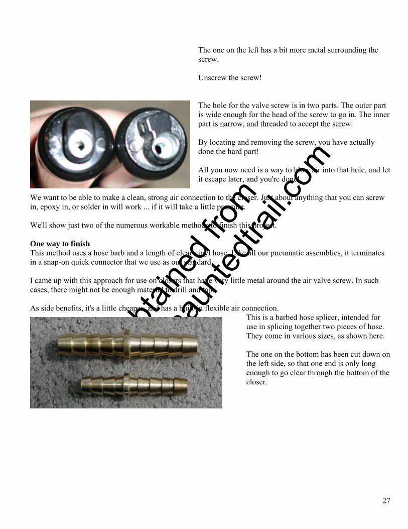
he one on the left has a bit more metal surrounding the
Unscrew the screw!
he hole for the valve screw is in two parts. The outer part
By locating and removing the screw, you have actually
All you now need is a way to blow air into that hole, and let
We want to be able to make a clean, strong air connection to the closer. Just about anything that you can screw
e'll show just two of the numerous workable methods to finish this project.
ne way to finish hose barb and a length of clear vinyl hose. Like all our pneumatic assemblies, it terminates
came up with this approach for use on closers that have very little metal around the air valve screw. In such
s side benefits, it's a little cheaper, and has a built-in flexible air connection. bed hose splicer, intended for
The one on the bottom has been cut down on
the
Tscrew.
Tis wide enough for the head of the screw to go in. The innerpart is narrow, and threaded to accept the screw.
done the hard part!
it escape later, and you're done!
in, epoxy in, or solder in will work ... if it will take a little pressure. W OThis method uses a in a snap-on quick connector that we use as our standard. I cases, there might not be enough material to drill and tap. A
This is a baruse in splicing together two pieces of hose.They come in various sizes, as shown here.
the left side, so that one end is only long enough to go clear through the bottom of closer.

O
btaine
d fro
m
Omarsh
aunte
dtrail
.com
The simplest way to cut down the hose barb is with a pipe and tubing cutter. Failing that, use a hacksaw. In either case, clean up the cut with a file or sandpaper.
28
The trimmed barb is only long enough to go clear through the bottom of the closer.
The inner threads in the hole are too small for the hose barb. The outer part of the hole is too large.
We'll drill out the inner part just enough to make a very tight fit with the cut-down hose barb.
Use caution in drilling. It's best to firmly clamp the closer while working on it.
Make sure the hole and the hose barb are clean and grease-free! Then, epoxy the barb into the hole.
If your epoxy is runny, or slow to set, make the hole a tight fit, jam in the barb, and then
O
btaine
d fro
m
Omarsh
aunte
dtrail
.com
pour the epoxy between the barb and the inner wall of the hole.
If your epoxy is thick, or sets fast, roll the barb in the epoxy until it has built up a thick collar of glue, and shove that into the hole, while giving it a twist.
Or make up your own technique!
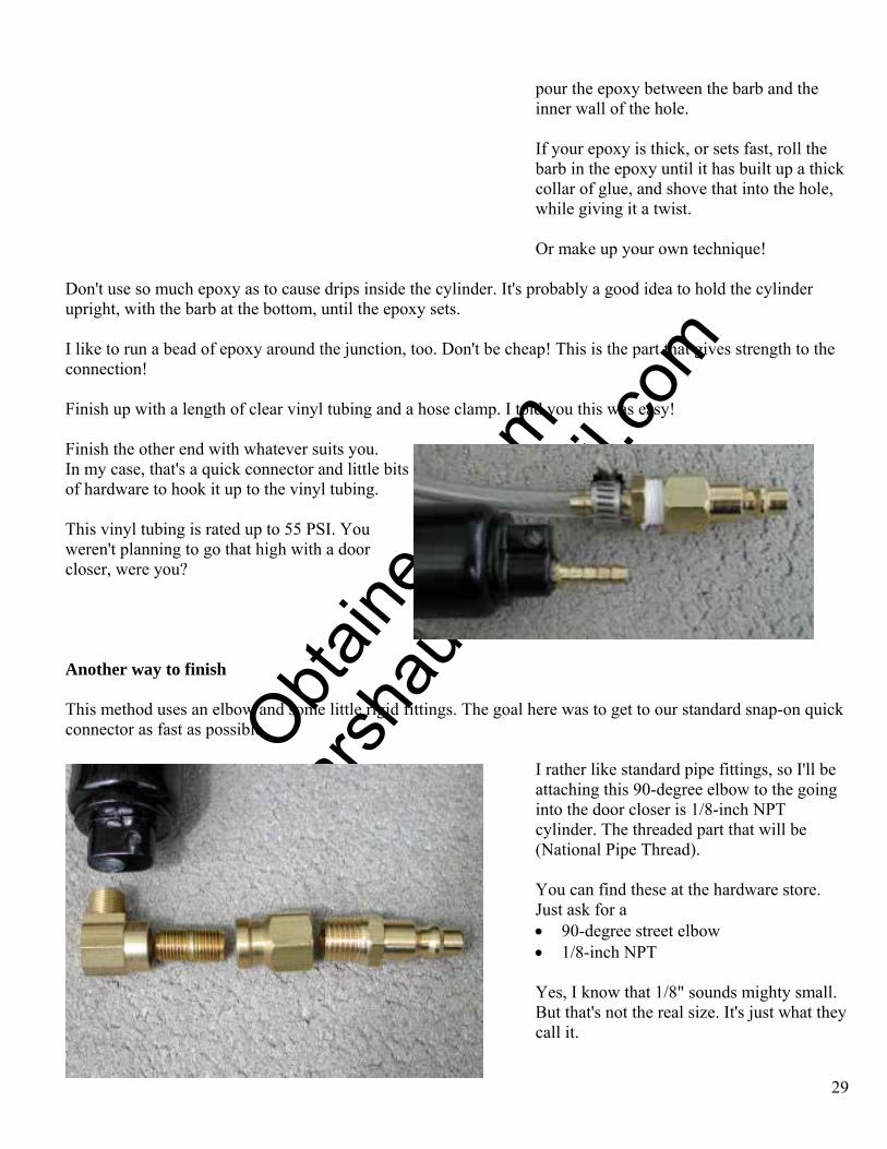
Don't use so much epoxy as to cause drips inside the cylinder. It's probably a good idea to hold the cylinder upright, with the barb at the bottom, until the epoxy sets. I like to run a bead of epoxy around the junction, too. Don't be cheap! This is the part that gives strength to the connection! Finish up with a length of clear vinyl tubing and a hose clamp. I told you this was easy! Finish the other end with whatever suits you. In my case, that's a quick connector and little bits of hardware to hook it up to the vinyl tubing. This vinyl tubing is rated up to 55 PSI. You weren't planning to go that high with a door closer, were you? Another way to finish This method uses an elbow and some little rigid fittings. The goal here was to get to our standard snap-on quick connector as fast as possible.
I rather like standard pipe fittings, so I'll be attaching this 90-degree elbow to the going into the door closer is 1/8-inch NPT cylinder. The threaded part that will be (National Pipe Thread).
You can find these at the hardware store. Just ask for a • 90-degree street elbow • 1/8-inch NPT
Yes, I know that 1/8" sounds mighty small. But that's not the real size. It's just what they call it.
29
O
btaine
d fro
m
Omarsh
aunte
dtrail
.com
The "street" part means one side is male, the other female. (A regular elbow is female on both sides and will require an additional nipple to hook up.)
Other parts: 1/8" close nipple, 1/8" to 1/4" reducer, and male quick connector.
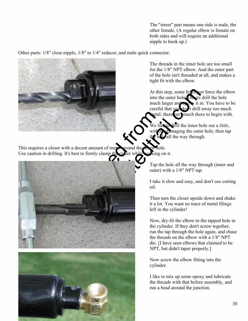
The threads in the inner hole are too small for the 1/8" NPT elbow. And the outer part of the hole isn't threaded at all, and makes a tight fit with the elbow.
At this step, some folks just force the elbow into the outer hole. Others drill the hole much larger and epoxy it in. You have to be careful that you don't drill away too much metal; there isn't much there to begin with. We like to drill the inner hole out a little, without damaging the outer hole, then tap the hole all the way through.
This requires a closer with a decent amount of metal around the screw hole. Use caution in drilling. It's best to firmly clamp the closer while working on it.
Tap the hole all the way through (inner and outer) with a 1/8" NPT tap.
30
I take it slow and easy, and don't use cutting oil.
Then turn the closer upside down and shake it a lot. You want no trace of metal filings left in the cylinder!
Now, dry-fit the elbow to the tapped hole in the cylinder. If they don't screw together, run the tap through the hole again, and chase the threads on the elbow with a 1/8" NPT die. [I have seen elbows that claimed to be NPT, but didn't taper properly.] Now screw the elbow fitting into the cylinder.
I like to mix up some epoxy and lubricate the threads with that before assembly, and run a bead around the junction.
O
btaine
d fro
m
Omarsh
aunte
dtrail
.com
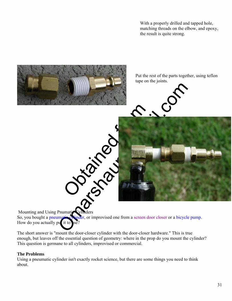
With a properly drilled and tapped hole, matching threads on the elbow, and epoxy, the result is quite strong.
Put the rest of the parts together, using teflon tape on the joints.
We're done!
Mounting and Using Pnumatic Cylinders So, you bought a pneumatic cylinder, or improvised one from a screen door closer or a bicycle pump. How do you actually put it to use? The short answer is "mount the door-closer cylinder with the door-closer hardware." This is true enough, but leaves off the essential question of geometry: where in the prop do you mount the cylinder? This question is germane to all cylinders, improvised or commercial. The Problems Using a pneumatic cylinder isn't exactly rocket science, but there are some things you need to think about.
31
O
btaine
d fro
m
Omarsh
aunte
dtrail
.com
32
Geometry This problem involves figuring out where to put the cylinder in order to get the motion that you desire when it is activated. Your best bet is to measure the cylinder at rest, and extended. Then think about two triangles, with triangle #1 having two sides exactly like those of triangle #1. They differ only in the length of the third side (the cylinder). Cylinder Body Now, where do you hide the body of the cylinder? It's a fact of life that a normal pneumatic cylinder will less than double when activated. If the
cylinder is 2' long at rest, when activated it will be a tad less than 4' long. [There are exceptions, multistage cylinders that telescope like radio antennas. We can't afford those.] It works the other way, too. If you want something to jump up 2', you start with a 2' cylinder that
extends to a total of 4'. Where do you hide the extra 2' of cylinder while the prop is at rest?
Air Feed Position In order to activate a pneumatic prop, you need a way to feed it a supply of compressed air. Commercial air cylinders usually have air connections nicely placed on the cylinder body pointing out, perpendicular to the axis of the cylinder. Haunt Air Manager (HAM) The Haunt Air Manager is a standard component used for pneumatic effects in our haunt. In one package, it provides electrical triggering, pressure regulation, exhaust regulation, and air storage. Why bother? In order to activate a pneumatic prop, you need a way to feed it a supply of compressed air. Assuming that you already have a compressor and a bit of hose, the problem is reduced to a valve that can be used to turn on the air flow. But there is one additional problem. Let's consider a little thought experiment... Think of a toy balloon as your air-activated prop. Just imagine the balloon painted with a monster face, and inflating it causes the monster to suddenly appear in front of the trick-or-treaters. You connect the balloon to a compressor and a valve that can be used to send air into the balloon on command. Kids come up the walkway; you open the valve; air flows into the balloon, making it expand; kids run away in terror. Now what? I mean, now, how do you prepare for the next batch of kids? You have to let the air out of the balloon. This allows the balloon to deflate, resetting the scare for the next batch of kids. But we didn't plan for that! All we have is a way to get air into the balloon. If we open the valve again, even more air will go into the balloon. We need a way to exhaust the air. There are numerous ways to do this. Two-Way Valve Method The cheapest method is to insert a tee into the air line between the valve and pneumatic effect.
O
btaine
d fro
m
Omarsh
aunte
dtrail
.com
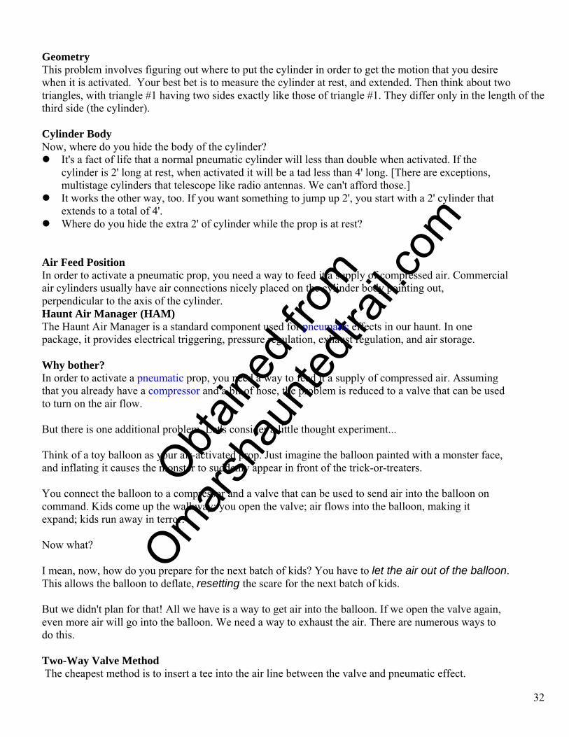
• The side branch of the tee goes to a cheap "bleeder" valve, or even a piece of tubing, crimped or crushed to slow the escape of air.
• When the valve is triggered, air rushes into the prop and out the escape hole. But flow through the escape hole is slow enough so that there is sufficient air to activate the prop.
• When the valve is turned off, air from the prop flows back and out the bleeder. • This approach is often used with a two-way valve, which has only two ports, in and out, and
works like a simple on/off switch.
33
When power is applied, compressed air goes into the pneumatic cylinder, and escapes through the bleeder valve. When power is removed, exhaust air exits through the bleeder.
When using a two-way valve, the faster you want the prop to reset, the wider you must open the bleeder, and the more air that is wasted when you activate the prop. This will also cause your compressor to cycle more frequently. Three-Way Valve Method I prefer the use of a three-way valve.
• A three-way valve has three connections: a "normally open", "normally closed", and common. The valve has two pathways through the valve: it can connect the common to the normally open port, or the common to the normally closed port.
• When the valve is activated, air flows from the normally closed port, through to the common, and into the prop.
• When the valve is deactivated, air flow from the normally closed port stops, but the other port opens.
• The air from the prop flows back, through the normally open port, and is exhausted. • By placing a flow control on the exhaust port of the two-way valve, you can control the speed
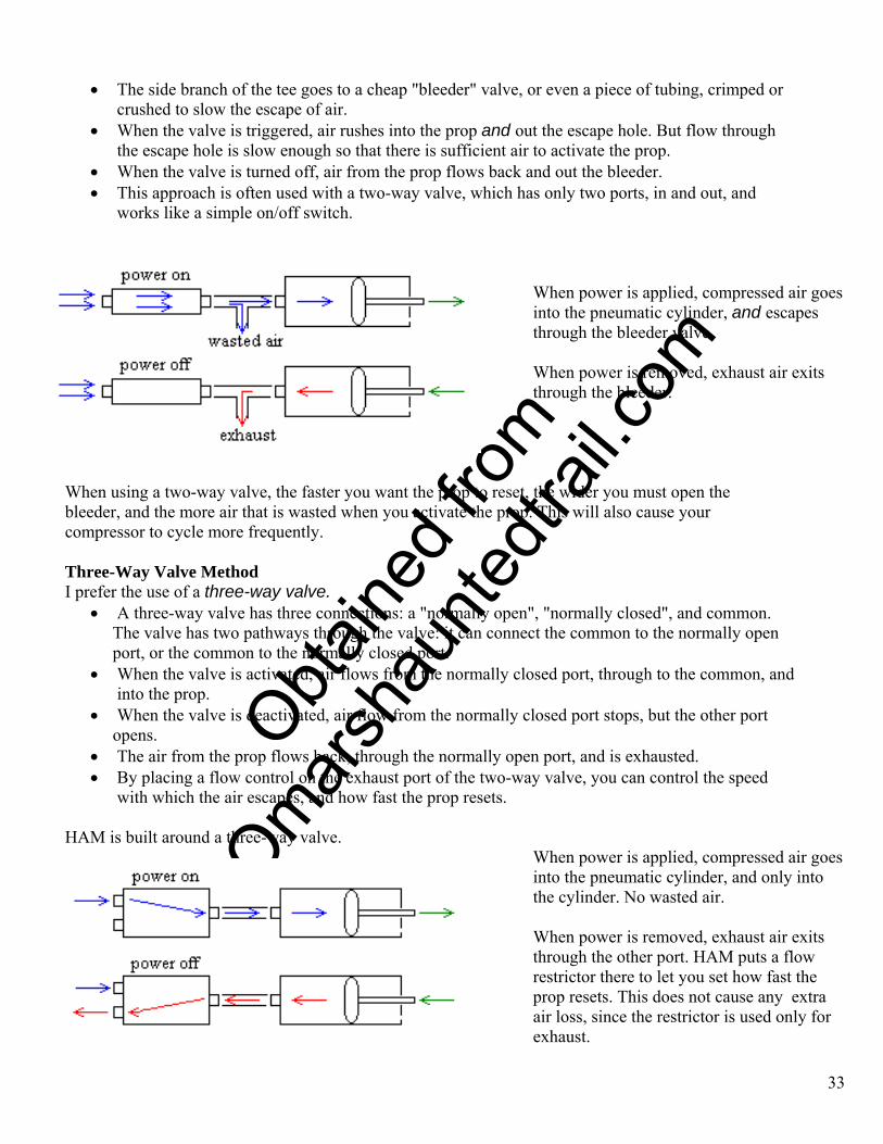
with which the air escapes, and how fast the prop resets. HAM is built around a three-way valve.
When power is applied, compressed air goes into the pneumatic cylinder, and only into the cylinder. No wasted air. When power is removed, exhaust air exits through the other port. HAM puts a flow restrictor there to let you set how fast the prop resets. This does not cause any extra air loss, since the restrictor is used only for exhaust.
O
btaine
d fro
m
Omarsh
aunte
dtrail
.com
Note that just providing a way for the air from the prop to escape isn't always enough for the prop to reset fully, or in a timely fashion. If you open the stem on an air mattress, some of the air will indeed escape, but not all of it, and not rapidly. That's one reason why some people like to use screen door closers as pneumatic cylinders - they contain a heavy spring that will automatically reset the prop, if you allow the air to escape. A little slice of HAM
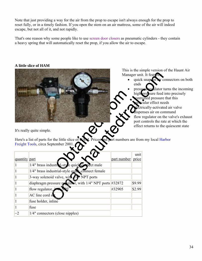
This is the simple version of the Haunt Air Manager unit. It features:
• quick snap-on air connectors on both ends
• pressure regulator turns the incoming high-pressure feed into precisely controlled pressure that this particular effect needs
• electrically-activated air valve dispenses air on command
• flow regulator on the valve's exhaust port controls the rate at which the effect returns to the quiescent state
It's really quite simple. Here's a list of parts for the little slice of HAM. Prices and part numbers are from my local Harbor Freight Tools, circa September 2001.
quantity part part numberunit
price1 1/4" brass industrial-style quick-connect male 1 1/4" brass industrial-style quick-connect female 1 3-way solenoid valve, with 1/4" NPT ports 1 diaphragm pressure regulator, with 1/4" NPT ports #32872 $9.991 flow regulator, 1/4" NPT #32905 $2.991 AC line cord set 1 fuse holder, inline 1 fuse ~2 1/4" connectors (close nipples)
34
O
btaine
d fro
m
Omarsh
aunte
dtrail
.com
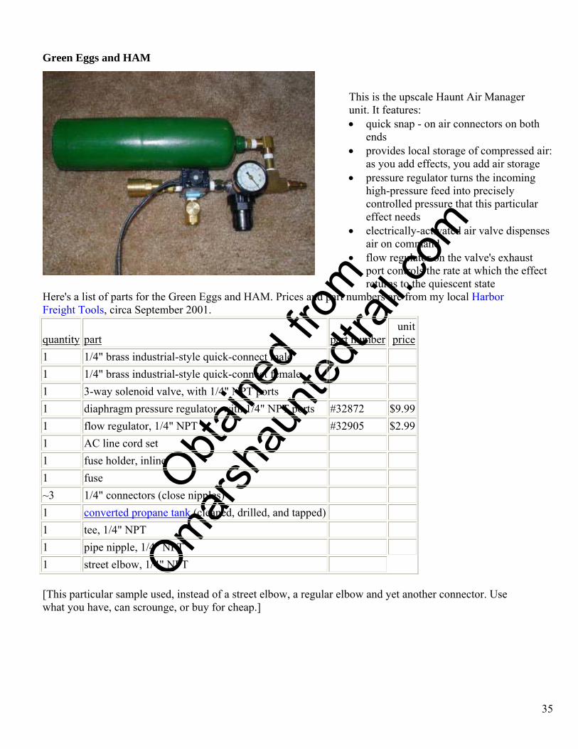
Green Eggs and HAM
This is the upscale Haunt Air Manager unit. It features: • quick snap - on air connectors on both
ends • provides local storage of compressed air:
as you add effects, you add air storage • pressure regulator turns the incoming
high-pressure feed into precisely controlled pressure that this particular effect needs
• electrically-activated air valve dispenses air on command
• flow regulator on the valve's exhaust port controls the rate at which the effect returns to the quiescent state
Here's a list of parts for the Green Eggs and HAM. Prices and part numbers are from my local Harbor Freight Tools, circa September 2001.
quantity part part numberunit
price1 1/4" brass industrial-style quick-connect male 1 1/4" brass industrial-style quick-connect female 1 3-way solenoid valve, with 1/4" NPT ports 1 diaphragm pressure regulator, with 1/4" NPT ports #32872 $9.99 1 flow regulator, 1/4" NPT #32905 $2.99 1 AC line cord set 1 fuse holder, inline 1 fuse ~3 1/4" connectors (close nipples) 1 converted propane tank (cleaned, drilled, and tapped) 1 tee, 1/4" NPT 1 pipe nipple, 1/4" NPT 1 street elbow, 1/4" NPT
[This particular sample used, instead of a street elbow, a regular elbow and yet another connector. Use what you have, can scrounge, or buy for cheap.]
35
O
btaine
d fro
m
Omarsh
aunte
dtrail
.com
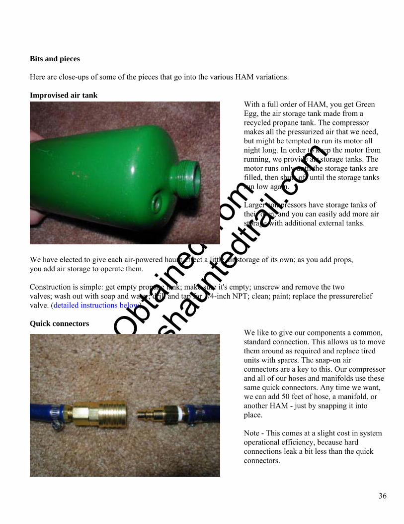
Bits and pieces Here are close-ups of some of the pieces that go into the various HAM variations. Improvised air tank
With a full order of HAM, you get Green Egg, the air storage tank made from a recycled propane tank. The compressor makes all the pressurized air that we need, but might be tempted to run its motor all night long. In order to keep the motor from running, we provide air storage tanks. The motor runs only until the storage tanks are filled, then shuts off until the storage tanks run low again.
36
Larger compressors have storage tanks of their own, and you can easily add more air storage with additional external tanks.
We have elected to give each air-powered haunt effect a little air storage of its own; as you add props, you add air storage to operate them. Construction is simple: get empty propane tank; make sure it's empty; unscrew and remove the two valves; wash out with soap and water; drill and tap for 1/4-inch NPT; clean; paint; replace the pressurerelief valve. (detailed instructions below) Quick connectors
We like to give our components a common, standard connection. This allows us to move them around as required and replace tired units with spares. The snap-on air connectors are a key to this. Our compressor and all of our hoses and manifolds use these same quick connectors. Any time we want, we can add 50 feet of hose, a manifold, or another HAM - just by snapping it into place.
Note - This comes at a slight cost in system operational efficiency, because hard connections leak a bit less than the quick connectors.
O
btaine
d fro
m
Omarsh
aunte
dtrail
.com
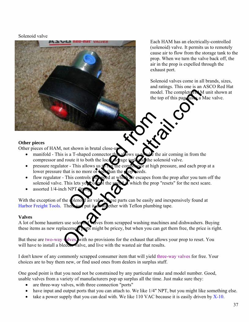
Solenoid valve
Each HAM has an electrically-controlled (solenoid) valve. It permits us to remotely cause air to flow from the storage tank to the prop. When we turn the valve back off, the air in the prop is expelled through the exhaust port.
37
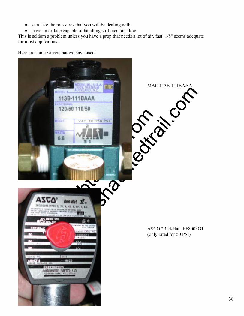
Solenoid valves come in all brands, sizes, and ratings. This one is an ASCO Red Hat model. The complete HAM unit shown at the top of this page uses a Mac valve.
Other pieces Other pieces of HAM, not shown in brutal close-up:
• manifold - This is a T-shaped connector that allows us to take the air coming in from the compressor and route it to both the local storage tank and the solenoid valve.
• pressure regulator - This allows us to run the compressor at high pressure, and each prop at a lower pressure that is no more or less than the prop needs.
• flow regulator - This controls the speed at which air escapes from the prop after you turn off the solenoid valve. This lets you control the speed at which the prop "resets" for the next scare.
• assorted 1/4-inch NPT fittings With the exception of the solenoid air valve, these parts can be easily and inexpensively found at Harbor Freight Tools. Then, just put it all together with Teflon plumbing tape. Valves A lot of home haunters use solenoid valves from scrapped washing machines and dishwashers. Buying these items as new replacement parts might be pricey, but when you can get them free, the price is right. But these are two-way valves, with no provisions for the exhaust that allows your prop to reset. You will have to install a bleeder valve, and live with the wasted air that results. I don't know of any commonly scrapped consumer item that will yield three-way valves for free. Your choices are to buy them new, or find used ones from dealers in surplus stuff. One good point is that you need not be constrained by any particular make and model number. Good, usable valves from a variety of manufacturers pop up surplus all the time. Just make sure they:
• are three-way valves, with three connection "ports" • have input and output ports that you can attach to. We like 1/4" NPT, but you might like something else. • take a power supply that you can deal with. We like 110 VAC because it is easily driven by X-10.
O
btaine
d fro
m
Omarsh
aunte
dtrail
.com
• can take the pressures that you will be dealing with • have an oriface capable of handling sufficient air flow
This is seldom a problem unless you have a prop that needs a lot of air, fast. 1/8" seems adequate for most applicaions. Here are some valves that we have used:
38
MAC 113B-111BAAA
ASCO "Red-Hat" EF8003G1 (only rated for 50 PSI)
O
btaine
d fro
m
Omarsh
aunte
dtrail
.com
Solenoid Valves To electronically control compressed air you need a solenoid valve. Introduction
• A solenoid is a coil of wire that becomes magnetized when electricity is run through it. • Solenoids often have a hole in the middle and a protruding metal rod that is pushed or pulled by
magnetism when power is applied. • A solenoid valve uses a solenoid to actuate a valve. This lets you control the vlow of water, air, or
other things with electricity. There are many different types of solenoid valves available, and many companies that make them. When selecting a solenoid valve, you must pay attention to:
• Coil voltage, current, AC or DC, and intermittant versus continuous duty. • valve type • aperture size • pressure rating, such as "50 PSI" • materials (medium) that it can control, such as "air/water" • type of connection to each port, such as "1/4" NPT"
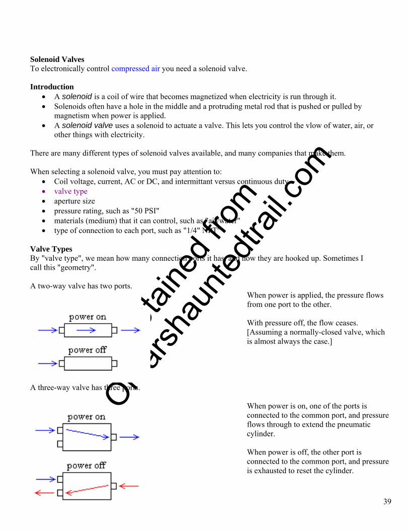
Valve Types By "valve type", we mean how many connection ports it has, and how they are hooked up. Sometimes I call this "geometry". A two-way valve has two ports.
When power is applied, the pressure flows from one port to the other.
With pressure off, the flow ceases. [Assuming a normally-closed valve, which is almost always the case.]
A three-way valve has three ports.
When power is on, one of the ports is connected to the common port, and pressure flows through to extend the pneumatic cylinder.
39
When power is off, the other port is connected to the common port, and pressure is exhausted to reset the cylinder.

O
btaine
d fro
m
Omarsh
aunte
dtrail
.com
This is the pneumatic equivalent of a single-pole single-throw electrical
switch. A four-way valve has four ports.
40
With power on, one set of ports is connected straight through to the other set of ports.
With power off, the connection is reversed.
If a valve has more ports than you need, you can plug them up to get a lesser configuration.
A four-way valve can act as a three-way by plugging one of the ports.
A four-way valve can act as a two-way by plugging two of the ports.
A three-way valve can act as a two-way by plugging one of the ports.
O
btaine
d fro
m
Omarsh
aunte
dtrail
.com
Wiring Your solenoid valve should come with a specification sheet that includes wiring information.
41
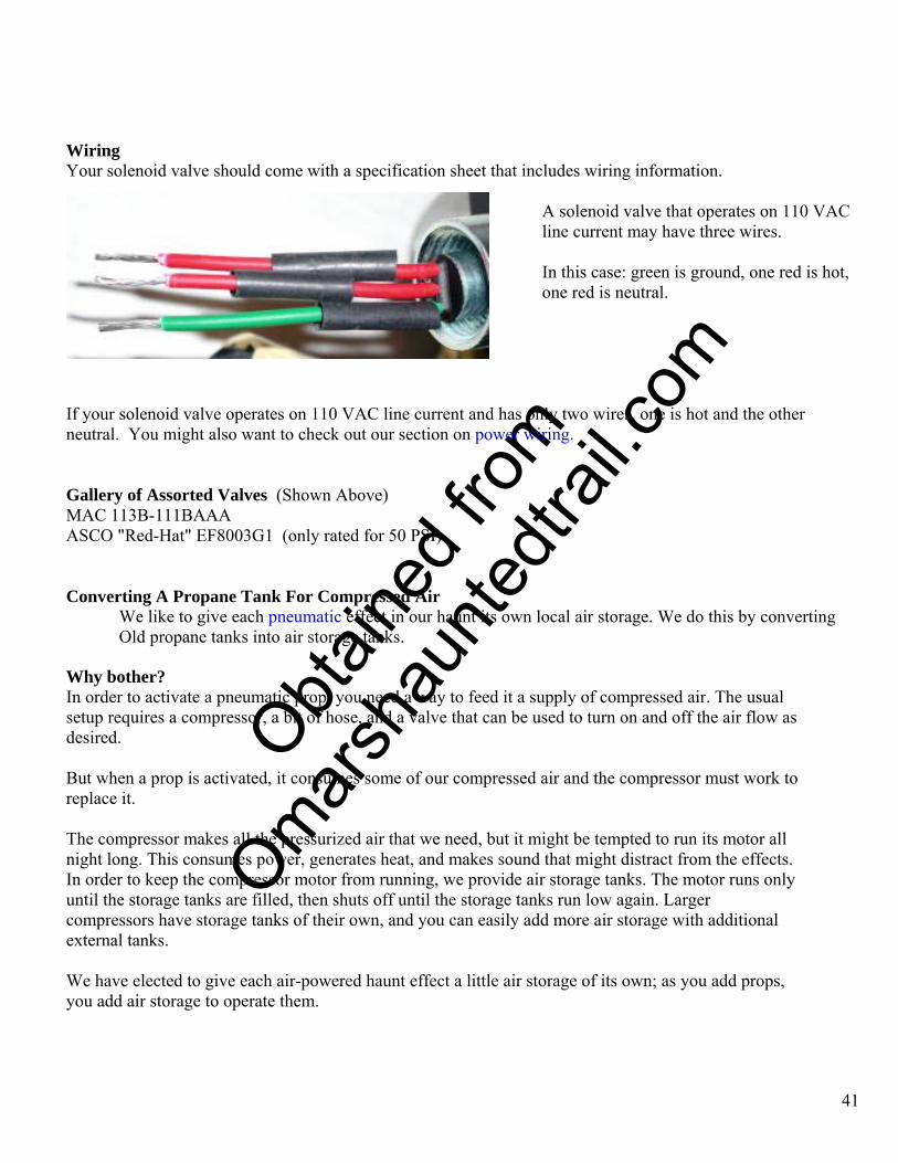
A solenoid valve that operates on 110 VAC line current may have three wires.
In this case: green is ground, one red is hot, one red is neutral.
If your solenoid valve operates on 110 VAC line current and has only two wires, one is hot and the other neutral. You might also want to check out our section on power wiring. Gallery of Assorted Valves (Shown Above) MAC 113B-111BAAA ASCO "Red-Hat" EF8003G1 (only rated for 50 PSI) Converting A Propane Tank For Compressed Air
We like to give each pneumatic effect in our haunt its own local air storage. We do this by converting Old propane tanks into air storage tanks.
Why bother? In order to activate a pneumatic prop, you need a way to feed it a supply of compressed air. The usual setup requires a compressor, a bit of hose, and a valve that can be used to turn on and off the air flow as desired. But when a prop is activated, it consumes some of our compressed air and the compressor must work to replace it. The compressor makes all the pressurized air that we need, but it might be tempted to run its motor all night long. This consumes power, generates heat, and makes sound that might distract from the effects. In order to keep the compressor motor from running, we provide air storage tanks. The motor runs only until the storage tanks are filled, then shuts off until the storage tanks run low again. Larger compressors have storage tanks of their own, and you can easily add more air storage with additional external tanks. We have elected to give each air-powered haunt effect a little air storage of its own; as you add props, you add air storage to operate them.
O
btaine
d fro
m
Omarsh
aunte
dtrail
.com
General Procedure
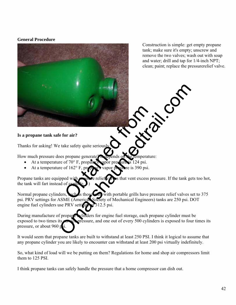
Construction is simple: get empty propane tank; make sure it's empty; unscrew and remove the two valves; wash out with soap and water; drill and tap for 1/4-inch NPT; clean; paint; replace the pressurerelief valve.
Is a propane tank safe for air? Thanks for asking! We take safety quite seriously. How much pressure does propane generate? It depends on the temperature:
• At a temperature of 70° F, propane's vapor pressure is 124 psi. • At a temperature of 162° F, propane's vapor pressure is 390 psi.
Propane tanks are equipped with pressure relief valves that vent excess pressure. If the tank gets too hot, the tank will fart instead of explode. :-) Normal propane cylinders, such as those used with portable grills have pressure relief valves set to 375 psi. PRV settings for ASME (American Society of Mechanical Engineers) tanks are 250 psi. DOT engine fuel cylinders use PRV settings of 312.5 psi. During manufacture of propane cylinders for engine fuel storage, each propane cylinder must be exposed to two times its service pressure, and one out of every 500 cylinders is exposed to four times its pressure, or about 960 psi. It would seem that propane tanks are built to withstand at least 250 PSI. I think it logical to assume that any propane cylinder you are likely to encounter can withstand at least 200 psi virtually indefinitely. So, what kind of load will we be putting on them? Regulations for home and shop air compressors limit them to 125 PSI. I think propane tanks can safely handle the pressure that a home compressor can dish out.
42
O
btaine
d fro
m
Omarsh
aunte
dtrail
.com
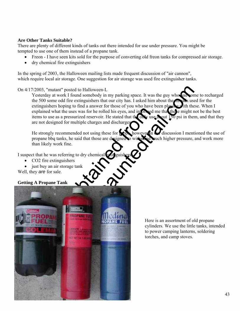
Are Other Tanks Suitable? There are plenty of different kinds of tanks out there intended for use under pressure. You might be tempted to use one of them instead of a propane tank.
• Freon - I have seen kits sold for the purpose of converting old freon tanks for compressed air storage. • dry chemical fire extinguishers
In the spring of 2003, the Halloween mailing lists made frequent discussion of "air cannon", which require local air storage. One suggestion for air storage was used fire extinguisher tanks. On 4/17/2003, "mutant" posted to Halloween-L
Yesterday at work I found somebody in my parking space. It was the guy who had come to recharged the 500 some odd fire extinguishers that our city has. I asked him about the threads used for the extinguishers hoping to find a answer for those of you who have been playing with these. When I explained what the uses was for he rolled his eyes, and informed me that these might not be the best items to use as a pressurized reservoir. He stated that the only use about 150 psi in them, and that they are not designed for multiple charges and discharges.
He strongly recommended not using these for props, however in our discussion I mentioned the use of propane bbq tanks, he said that those are designed to withstand much higher pressure, and work more than likely work fine.
I suspect that he was referring to dry chemical extinguishers.
• CO2 fire extinguishers • just buy an air storage tank
Well, they are for sale. Getting A Propane Tank
43
Here is an assortment of old propane cylinders. We use the little tanks, intended to power camping lanterns, soldering torches, and camp stoves.
O
btaine
d fro
m
Omarsh
aunte
dtrail
.com
Technically, these tanks can be refilled, but it is illegal to transport them after refilling. Effectively, empty tanks are worthless. If you don't use propane, I suggest asking friends, especially those who camp out, for an empty. These are usually thrown away, and finding another use for them is a good thing. You might also ask at stores that sell camping equipment. Perhaps, as a service to customers, they accept old tanks. You might also check your local dump or recycling depot. I wouldn't try to empty a full propane tank. That's wasteful. But if you really want to start with a full one, it is possible.
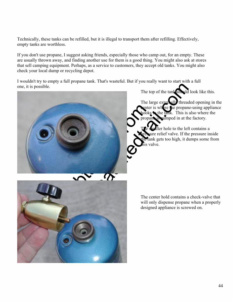
The top of the tank should look like this.
44
The large externally threaded opening in the center is where the propane-using appliance hooks to the tank. This is also where the propane is pumped in at the factory.
The smaller hole to the left contains a pressure relief valve. If the pressure inside the tank gets too high, it dumps some from this valve.
The center hold contains a check-valve that will only dispense propane when a properly designed appliance is screwed on.

O
btaine
d fro
m
Omarsh
aunte
dtrail
.com
Finish Emptying The Tank Even when the tank runs so low that it is no longer useful, there is probably still some propane inside. We must finish emptying the tank. The small propane tanks used for this project don't have a valve you can just open to let the gas out. They have a safety connection that only lets out gas when the tank is attached to something that uses it. In order to empty the tank, you have to connect it to some gadget that uses propane. This might be a lantern, stove, or torch.
In my case, I attached a torch, turned on the gas, and didn't light it. And out goes the gas.
45
It is important to do this outside, and away from all sources of ignition. Since my tank was nearly empty, venting the flammable gas to the atmosphere wasn't much of a safety hazard.
If you want to empty a full tank, I suggest using it up: hook it to a stove or something, light it, and let it burn out. After the tank is empty, remove the tank. Now, there are still two things in the tank: first a little bit of extra gas that doesn't have enough pressure to push out; second, some of the "odorant" that they add to make the gas smell. Propane Tank Preparation The next step is to allow free flow of air in and out of the tank. There are usually two valves on the tank: One big one in the middle, where you hook it up to something; one small one to vent excess pressure.
Both valves have removable spring "cores". Just unscrew them and they fall out. The valves cores themselves are similar to those used in automobile tires, and they unscrew the same way.
O
btaine
d fro
m
Omarsh
aunte
dtrail
.com
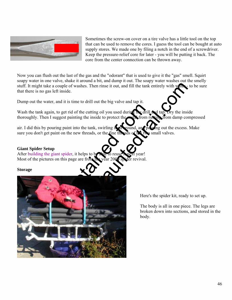
Sometimes the screw-on cover on a tire valve has a little tool on the top that can be used to remove the cores. I guess the tool can be bought at auto supply stores. We made one by filing a notch in the end of a screwdriver. Keep the pressure-relief core for later - you will be putting it back. The core from the center connection can be thrown away.
Now you can flush out the last of the gas and the "odorant" that is used to give it the "gas" smell. Squirt soapy water in one valve, shake it around a bit, and dump it out. The soapy water washes out the smelly stuff. It might take a couple of washes. Then rinse it out, and fill the tank entirely with water - to be sure that there is no gas left inside. Dump out the water, and it is time to drill out the big valve and tap it. Wash the tank again, to get rid of the cutting oil you used during the drill and tap. Dry the inside thoroughly. Then I suggest painting the inside to protect the metal from rusting from damp compressed air. I did this by pouring paint into the tank, swirling it all around, and pouring out the excess. Make sure you don't get paint on the new threads, or the fine threads of the two small valves. Giant Spider Setup After building the giant spider, it helps to be able to reuse it next year! Most of the pictures on this page are from the year 2000 spider revival. Storage
46
Here's the spider kit, ready to set up.
The body is all in one piece. The legs are broken down into sections, and stored in the body.
O
btaine
d fro
m
Omarsh
aunte
dtrail
.com
Techniques
47
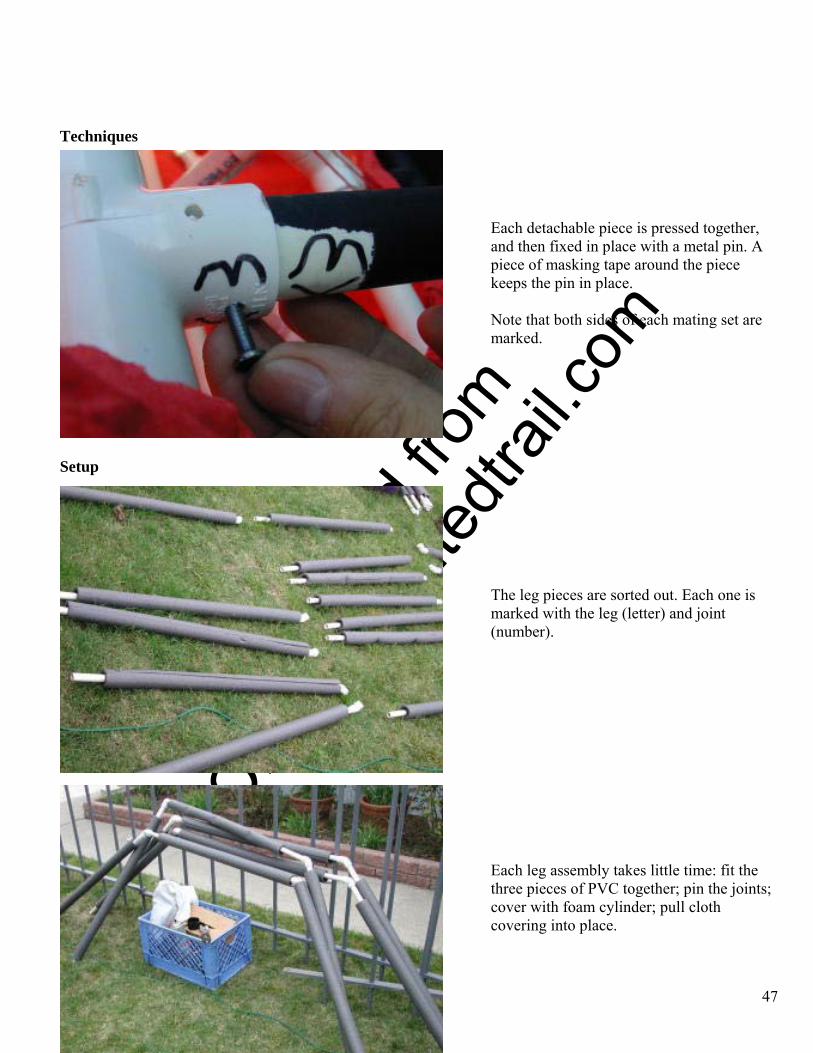
Each detachable piece is pressed together, and then fixed in place with a metal pin. A piece of masking tape around the piece keeps the pin in place.
Note that both sides of each mating set are marked.
Setup
The leg pieces are sorted out. Each one is marked with the leg (letter) and joint (number).
Each leg assembly takes little time: fit the three pieces of PVC together; pin the joints; cover with foam cylinder; pull cloth covering into place.

O
btaine
d fro
m
Omarsh
aunte
dtrail
.com
48
The base is positioned on the roof, and the body placed on top.
The base sits firmly on the roof. For added protection against sliding down the roof, a rope goes up, over the ridgeline, and fastens to a Heavy Object on the back side.
Pads like these protect the roof against abrasion from the safety rope.
The legs are assembled on the ground, then handed up to the worker on the roof.
O
btaine
d fro
m
Omarsh
aunte
dtrail
.com
49
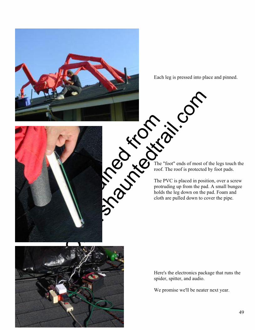
Each leg is pressed into place and pinned.
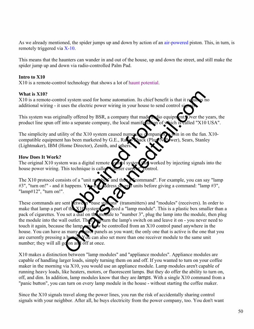
The "foot" ends of most of the legs touch the roof. The roof is protected by foot pads. The PVC is placed in position, over a screw protruding up from the pad. A small bungee holds the leg down on the pad. Foam and cloth are pulled down to cover the pipe.
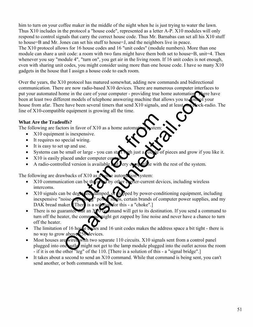
Here's the electronics package that runs the spider, spitter, and audio.
We promise we'll be neater next year.
O
btaine
d fro
m
Omarsh
aunte
dtrail
.com
50
As we already mentioned, the spider jumps up and down by action of an air-powered piston. This, in turn, is remotely triggered via X-10. This means that the haunters can wander in and out of the house, up and down the street, and still make the spider jump up and down via radio-controlled Palm Pad. Intro to X10 X10 is a remote-control technology that shows a lot of haunt potential. What is X10? X10 is a remote-control system used for home automation. Its chief benefit is that it requires no additional wiring - it uses the electric power wiring in your house to send control signals. This system was originally offered by BSR, a company that made audio equipment. Over the years, the product line spun off into a separate company, the local manifestation of which is called "X10 USA". The simplicity and utility of the X10 system caused numerous companies to join in on the fun. X10- compatible equipment has been marketed by G.E., Radio Shack (Plug-N-Power), Sears, Stanley (Lightmaker), IBM (Home Director), Zenith, and others. How Does It Work? The original X10 system was a digital remote control system that worked by injecting signals into the house power wiring. This technique is called "carrier current" control. The X10 protocol consists of a "unit number" and then a "command". For example, you can say "lamp #3", "turn on!" - and it happens. You can address several units before giving a command: "lamp #3", "lamp#12", "turn on!". These commands are sent between "base stations" (transmitters) and "modules" (receivers). In order to make that lamp a part of the X10 system, you need a "lamp module". This is a plastic box smaller than a pack of cigarettes. You set a dial on the module to "number 3", plug the lamp into the module, then plug the module into the wall outlet. Then you turn the lamp's switch on and leave it on - you never need to touch it again, because the lamp can now be controlled from an X10 control panel anywhere in the house. You can have as many control panels as you want; the only one that is active is the one that you are currently pressing a button. You can also set more than one receiver module to the same unit number; they will all go on and off at once. X10 makes a distinction between "lamp modules" and "appliance modules". Appliance modules are capable of handling larger loads, simply turning them on and off. If you wanted to turn on your coffee maker in the morning via X10, you would use an appliance module. Lamp modules aren't capable of running heavy loads, like heaters, motors, or fluorescent lamps. But they do offer the ability to turn on, off, and dim. In addition, lamp modules know that they are lamps. With a single X10 command from a "panic button", you can turn on every lamp module in the house - without starting the coffee maker. Since the X10 signals travel along the power lines, you run the risk of accidentally sharing control signals with your neighbor. After all, he buys electricity from the power company, too. You don't want
O
btaine
d fro
m
Omarsh
aunte
dtrail
.com
51
him to turn on your coffee maker in the middle of the night when he is just trying to water the lawn. Thus X10 includes in the protocol a "house code", represented as a letter A-P. X10 modules will only respond to control signals that carry the correct house code. Thus Mr. Barnabas can set all his X10 stuff to house=B and Mr. Jones can set his stuff to house=J, and the neighbors live in peace. The X10 protocol allows for 16 house codes and 16 "unit codes" (module numbers). More than one module can share a unit code: a room with two fans might have them both set to house=B, unit=4. Then whenever you say "module 4", "turn on", you get air in the living room. If 16 unit codes is not enough, even with sharing unit codes, you might consider using more than one house code. I have so many X10 gadgets in the house that I assign a house code to each room. Over the years, the X10 protocol has matured somewhat, adding new commands and bidirectional communication. There are now radio-based X10 devices. There are numerous computer interfaces to put your automated home in the care of your computer - providing true home automation. There have been at least two different models of telephone answering machine that allows you to control your house from afar. There have been several timers that send X10 signals, and at least one clock-radio. The line of X10-compatible equipment is growing all the time. What Are the Tradeoffs? The following are factors in favor of X10 as a home automation system:
• X10 equipment is inexpensive. • It requires no special wiring. • It is easy to set up and use. • Systems can be small or large - you can start with just a couple of pieces and grow if you like it. • X10 is easily placed under computer control. • A radio-controlled version is available and very compatible with the rest of the system.
The following are drawbacks of X10 as a home automation system:
• X10 communication can be thwarted by other carrier-current devices, including wireless intercoms.
• X10 signals can be degraded, damped, or stopped by power-conditioning equipment, including inexpensive "noise-supressing" power strips, certain brands of computer power supplies, and my DAK bread maker. [There is a solution for this - a "choke".]
• There is no guarantee that an X10 command will get to its destination. If you send a command to turn off the heater, the command might get zapped by line noise and never have a chance to turn off the heater.
• The limitation of 16 house codes and 16 unit codes makes the address space a bit tight - there is no way to grow above 256 devices.
• Most houses are wired with two separate 110 circuits. X10 signals sent from a control panel plugged into one outlet might not get to the lamp module plugged into the outlet across the room - if it is on the other "leg" of the 110. [There is a solution of this - a "signal bridge".]
• It takes about a second to send an X10 command. While that command is being sent, you can't send another, or both commands will be lost.
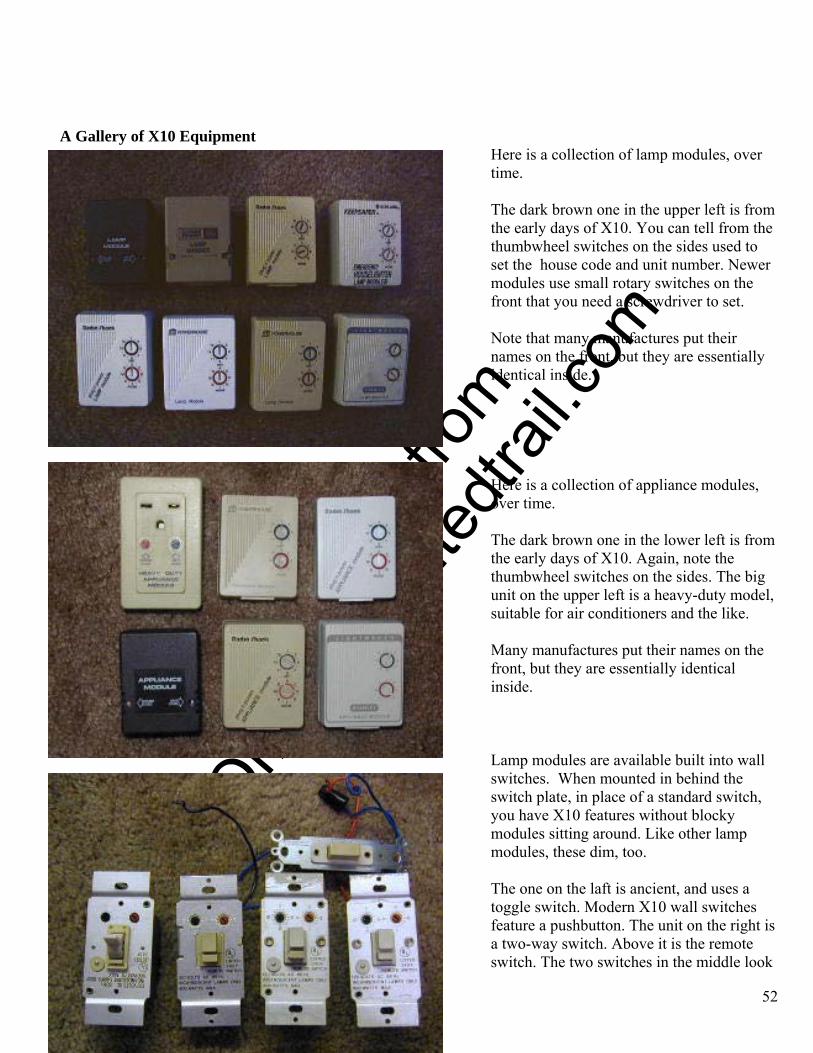
O
btaine
d fro
m
Omarsh
aunte
dtrail
.com
A Gallery of X10 Equipment
Here is a collection of lamp modules, over time.
52
The dark brown one in the upper left is from the early days of X10. You can tell from the thumbwheel switches on the sides used to set the house code and unit number. Newer modules use small rotary switches on the front that you need a screwdriver to set.
Note that many manufactures put their names on the front, but they are essentially identical inside.
Here is a collection of appliance modules, over time. The dark brown one in the lower left is from the early days of X10. Again, note the thumbwheel switches on the sides. The big unit on the upper left is a heavy-duty model, suitable for air conditioners and the like.
Many manufactures put their names on the front, but they are essentially identical inside.
Lamp modules are available built into wall switches. When mounted in behind the switch plate, in place of a standard switch, you have X10 features without blocky modules sitting around. Like other lamp modules, these dim, too.
The one on the laft is ancient, and uses a toggle switch. Modern X10 wall switches feature a pushbutton. The unit on the right is a two-way switch. Above it is the remote switch. The two switches in the middle look
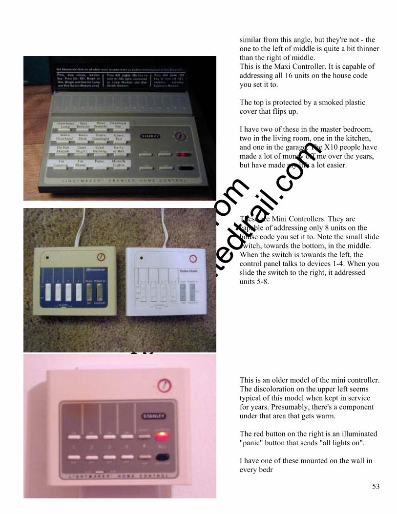
O
btaine
d fro
m
Omarsh
aunte
dtrail
.com
similar from this angle, but they're not - the one to the left of middle is quite a bit thinner than the right of middle.
53
This is the Maxi Controller. It is capable of addressing all 16 units on the house code you set it to.
The top is protected by a smoked plastic cover that flips up.
I have two of these in the master bedroom, two in the living room, one in the kitchen, and one in the garage. The X10 people have made a lot of money off me over the years, but have made my life a lot easier.
These are Mini Controllers. They are capable of addressing only 8 units on the house code you set it to. Note the small slide switch, towards the bottom, in the middle. When the switch is towards the left, the control panel talks to devices 1-4. When you slide the switch to the right, it addressed units 5-8.
This is an older model of the mini controller. The discoloration on the upper left seems typical of this model when kept in service for years. Presumably, there's a component under that area that gets warm.
The red button on the right is an illuminated "panic" button that sends "all lights on".
I have one of these mounted on the wall in every bedr
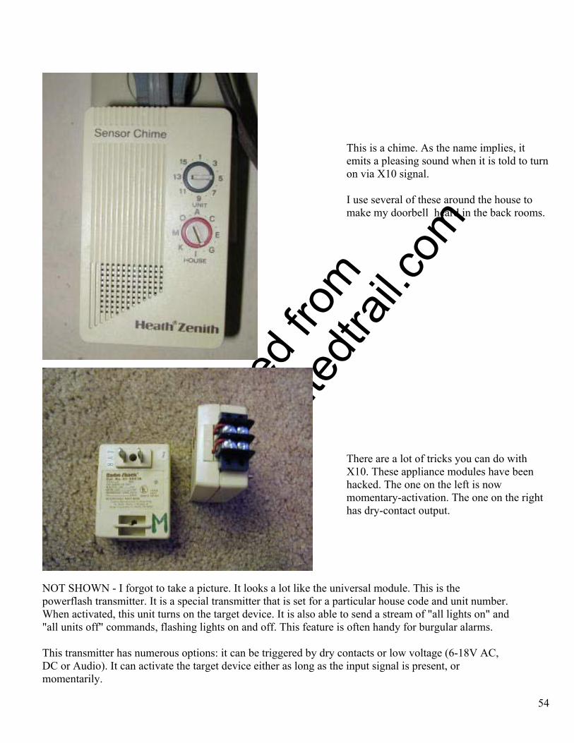
O
btaine
d fro
m
Omarsh
aunte
dtrail
.com
54
This is a chime. As the name implies, it emits a pleasing sound when it is told to turn on via X10 signal.
I use several of these around the house to make my doorbell heard in the back rooms.
There are a lot of tricks you can do with X10. These appliance modules have been hacked. The one on the left is now momentary-activation. The one on the right has dry-contact output.
NOT SHOWN - I forgot to take a picture. It looks a lot like the universal module. This is the powerflash transmitter. It is a special transmitter that is set for a particular house code and unit number. When activated, this unit turns on the target device. It is also able to send a stream of "all lights on" and "all units off" commands, flashing lights on and off. This feature is often handy for burgular alarms. This transmitter has numerous options: it can be triggered by dry contacts or low voltage (6-18V AC, DC or Audio). It can activate the target device either as long as the input signal is present, or momentarily.

O
btaine
d fro
m
Omarsh
aunte
dtrail
.com
I have one of these hooked up to my doorbell. When the bell is rung, the powerflash activates chimes in the back room.
55
This is the "universal module", sometimes called "sounder/actuator module" or "relay module". When activated by X-10 signal, it can emit a beep noise and/or close dry contacts. It can work in momentary mode, or leave the contacts closed until you tell it to open them again.
The dry contacts can switch up to 5A at 24VDC. I use one on my fog machine!
Wireless X10 Equipment The original X10 system was a digital remote control system that worked by injecting signals into the house power wiring. This technique is called "carrier current" control. Anywhere that you can get power, you can get put gadgets under X10 control and add control panels. Eventually, the X10 folks added a wireless form of X10 control. They did a good job of hooking the two together, so that wireless X10 controllers can activate standard carrier-current X10 modules.
This is the basic radio-control kit.
On the right are two versions of the hand-held remote control panel. They send signals to a special appliance module, on the left. It takes the radio signals and turns them into carrier-current signals that activate all standard X10 modules.
If it is a long distance between your transmitter and the receiver, you might
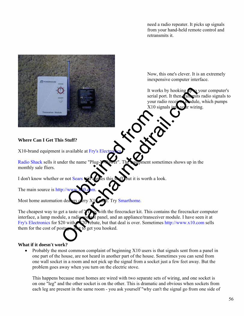
O
btaine
d fro
m
Omarsh
aunte
dtrail
.com
need a radio repeater. It picks up signals from your hand-held remote control and retransmits it.
56
Now, this one's clever. It is an extremely inexpensive computer interface. It works by hooking up to your computer's serial port. It then transmits radio signals to your radio receiver module, which pumps X10 signals into your wiring.
Where Can I Get This Stuff? X10-brand equipment is available at Fry's Electronics. Radio Shack sells it under the name "Plug-N-Power". The equipment sometimes shows up in the monthly sale fliers. I don't know whether or not Sears still carries this stuff, but it is worth a look. The main source is http://www.x10.com. Most home automation dealers carry X10 stuff. Try Smarthome. The cheapest way to get a taste of X10 is with the firecracker kit. This contains the firecracker computer interface, a lamp module, a radio control panel, and an appliance/transceiver module. I have seen it at Fry's Electronics for $20 with a $20 rebate, but that deal is over. Sometimes http://www.x10.com sells them for the cost of postage, just to get you hooked. What if it doesn't work?
• Probably the most common complaint of beginning X10 users is that signals sent from a panel in one part of the house, are not heard in another part of the house. Sometimes you can send from one wall socket in a room and not pick up the signal from a socket just a few feet away. But the problem goes away when you turn on the electric stove.
This happens because most homes are wired with two separate sets of wiring, and one socket is on one "leg" and the other socket is on the other. This is dramatic and obvious when sockets from each leg are present in the same room - you ask yourself "why can't the signal go from one side of
O
btaine
d fro
m
Omarsh
aunte
dtrail
.com
57
the room to the other?" The problem is a bit more subtle when you try to send from a socket on one leg in the bedroom to a socket on the other leg in the living room. When this fails, the beginning X10 user is likely to write it off as a distance problem.
These are all signs that you need a "signal bridge". The signal bridge takes whatever X10 signals it sees on one leg and lets them pass to the other. Signal bridges are relatively inexpensive. You can even make your own with a capacitor.
• If your neighbor's X10 equipment interferes with yours, you need a "signal block" to keep his
signals out of the power coming into your house. Signal blocks tend to be expensive, and must be installed at your main fuse panel by a professional electrician.
• Certain appliances in your home can generate signals that interfere with X10, or just "short out"
X10 signals. This usually requires that you locate the offending device and put a "noise filter" on it.
A common offender here is the "wireless intercom" that sends voice signals through the power line. Filtering those is not an option - if it can't send signals into the power wiring, it can't get its job done. And if it does, it interferes with the X10. If you are lucky, this will only happen when the intercom is actively transmitting. X10 remedies are a little exotic. Not all X10 dealers will have them. They are known to be available at Smarthome.
What about power strips and extension cords? If you have a nice, strong X10 signal, running your power through an extension cord is not going to cause it any trouble. Power strips come in at least three flavors, and some of them do cause trouble for X10.
• Plain-vanilla power strips just have a plug on one end and sockets on the other. They might have a switch and an indicator light, but nothing that processes the power that it conducts. This kind of power strip presents no problem at all to X10 signals.
• Power strips with just surge protection also do not hinder X10. The protection is usually done
with one or more MOVs, or perhaps a special gas-discharge tube. You can tell them by the claims on the box - the surge protection is a "feature", and they can only charge you more for it if they tell you about it.
• Power strips with "noise protection" or ones that claim to "reduce interference" do cause
problems with X10.
The cheapest way to do provide some noise control is to throw a cheap capacitor across the line. This will not only disrupt signals flowing through the power strip (from a transmitter in the bedroom to a receiver plugged in to the strip), but will also cause problems for any X10 device plugged in anywhere on the same leg of the 110. This one can be hard to diagnose, when a signal from the bedroom to the living room no longer gets through because you put a power strip on the computer in the den.
O
btaine
d fro
m
Omarsh
aunte
dtrail
.com
58
More expensive noise filtering schemes axist, using multiple capacitors and coils. They, too, are likely to cause trouble for X10 operation.
What Are the Tradeoffs? In order to consider X10 for haunt purposes, you must weigh the tradeoffs offered by this technology.
The following are factors in favor of X10 as a remote control system:
• X10 equipment is inexpensive. • It requires no special wiring. • It is easy to set up and use. • Systems can be small or large - you can start with just a couple of pieces and grow if you like it. • X10 is easily placed under computer control. • A radio-controlled version is available and very compatible with the rest of the system.
These favorable factors are considerable. Let's say you decide, on the spur of the moment, to put a fog machine there. You plug the machine into the power line, add an X10 module to control it, and you're ready to haunt! Want to trigger it from here? Plop down a mini control panel. Want the zombie in the graveyard to fog on demand? Give him a wireless controller.
You can't beat this stuff ... when it works.
The following are drawbacks of X10 as a remote control system:
• X10 communication can be thwarted by other carrier-current devices, including wireless intercoms. • X10 signals can be degraded, damped, or stopped by power-conditioning equipment, including
inexpensive "noise-supressing" power strips, certain brands of computer power supplies, and my DAK bread maker. [There is a solution for this - a "choke".]
• There is no guarantee that an X10 command will get to its destination. If you send a command to turn off the heater, the command might get zapped by line noise and never have a chance to turn off the heater.
• The limitation of 16 house codes and 16 unit codes makes the address space a bit tight - there is no way to grow above 256 devices.
• Most houses are wired with two separate 110 circuits. X10 signals sent from a control panel plugged into one outlet might not get to the lamp module plugged into the outlet across the room - if it is on the other "leg" of the 110. [There is a solution of this - a "signal bridge".]
• It takes about a second to send an X10 command. While that command is being sent, you can't send another, or both commands will be lost.
X10 bits useful in a haunt. The following X10 bits and pieces are handy for haunting:
O
btaine
d fro
m
Omarsh
aunte
dtrail
.com
59
• Appliance modules - Turn on and off 110 VAC on command. Use to control solenoid valves (for pneumatic props), strobes, and other 110 VAC gadgets.
• Radio control panel - Allows haunt operator to move around while still having complete control of X10 exxects.
• Computer interface - Send timed sequences of X10 commands. If your computer has multimedia capability, it can play the sound track, while triggering a series of effects synchronized to the sound.
• Lamp modules - Turning incandescent lamps on and off. • Sounder/actuator module - Control of any device that is triggered by dry contacts, including modified
fog machine remote controls.
Lamp modules might be used to turn on and dim lights before the haunt starts, to establish a setting. Lights should not be dimmed or brightened during the haunt. Sending dim and brighten commands takes a lot of time.
Haunt Requirements Ask yourself what you intend to automate via X10.
• Will you ever have to send more than one signal at once? If so, forget X10. Two signals sent at the same time "collide" with each other. Neither command takes effect. So if you have a PIR person-detector sending signals from the foot of the driveway to the fog machine, and an X10 transmitter from the doorbell to a scream box, you are at risk: if somebody enters the driveway at the same moment that somebody rings the doorbell, you get neither fog nor scream.
• Is split-second accuracy necessary? It takes a second or more to send an X10 command. • Will the haunt suffer if the unit fails to turn on or off? If an X10 command collides with another
command, or is wiped out by electrical noise, that command doesn't happen. If hooked up to an effect, the unit will not trigger. Or, if already triggered, will not turn off when so commanded. Just to be sure that the command gets through, you might want to press the button twice. But that's still not a guarantee.
Environmental Factors If you have decided that X10 is right for your haunt, you must then clean up the environment so that X10 will provide reliable service for you.
• Go out to the power pole and look for the big step-down transformer. Look at the wires coming from there and going to houses. Any house that shares a "pole pig" with you also shares X10 signals. Drop in and visit. Explain X10, and if they are using it, agree between you on who gets which house codes.
• Install a "signal bridge" between legs of the 110 electical power. • Examine all the power strips in your house. The ultra-cheapies are OK. The ones that claim to have
"noise protection" usually interfere with X10 signals. This can happen even if nothing is plugged in to the power strip - if the strip is plugged in to the wall, it can cause trouble. Test it.
• Get an audible X10 module and a transmitter. Move them around the house, sending signals. Make sure the signals get through.
• If the signals don't get thorough, unplug power strips, appliances, and computers, one by one. Turning them off is not enough - they must be unplugged. Leave them unplugged. When things work again, plug the things back, one at a time. When the signals stop, the thing you just plugged in is the trouble-maker.
• Isolate troublemakers with chokes.

O
btaine
d fro
m
Omarsh
aunte
dtrail
.com
• During haunt-critical times, don't run appliances with heavy electric motors, like washers and driers. They can put electrical noise into the power lines, interfering with X10. Don't use "wired wireless" intercoms.
The most important factor in using X10 in a haunt is that you can have numerous props triggered by X10, but should have few transmitters sending X10 signals. This reduces the chance of signals interfering with each other.
So, How Do I Haunt With X10? In 1999, we had the following effects running off X10 control:
• Fog machine. • Giant roof-spider animation. • Scream box. • Spider's rooftop shaving-cream squirter. • Spider's ground-based shaving-cream squirter.
These were controlled via a pair of hand-held radio remotes. One remote was given to the person handing out candy. If a kid was friendly, the candy lady could make the giant spider rear up and wave. Surly kids could be given a scream. The other controller was carried by somebody who sat out near the street, having a good view of the people coming and going. Since the folks inside were having a party, they didn't monitor their controls all the time. The outside person had first dibbs on the Trick Or Treaters!
The porch lights were also on X10. We set them to a reasonable dim level and left them there all night.
We actually had arguments over who got to go outside with the radio remote and control the spider as kids went up to the door!
We used this PalmPad in 2001, with a masking tape label for each effect.
60
O
btaine
d fro
m
Omarsh
aunte
dtrail
.com
We really liked the spider, and so did the neighbor kids. During setup, a van drove past and the driver slowed down to peek. A little girl stuck her head out the window, pointing up at our spider, yelling "There's a bug on the roof! There's a bug on the roof!" My only regret is that the spider didn't make any sounds. The sounds didn't need to be authentic. Who knows what a spider sounds like, anyhow? But a bit of animal sound, when the spider reared up, would have vastly increased the threat component of the fear factor. Perhaps some kind of chittering sound... We corrected the lack of sound in our year 2000 haunt. The canned sound board is in the center. The trigger relay is lower right with the X-10 module just above it. The wire from the sound board terminates in a 1/8" socket that connects to the amplified speakers.
Recordable Sound Box A pneumatic popup may be impressive, but it works better when there is synchronized light and sound. The more haunting I do, the more I am convinced that you can get better scares by attacking several of the senses at once.
Here, we discuss the construction of a programmable sound box. All you do is close a switch, and it plays back the sound that you recorded ... loudly. We also have a page outlining a scream box that makes a single, simple, basic scream.
• Gallery of Hackable Equipment
o Volatile Sound Recorders
o Nonvolatile Sound Recorders
• Assembly
• Fixing Hair Trigger
61
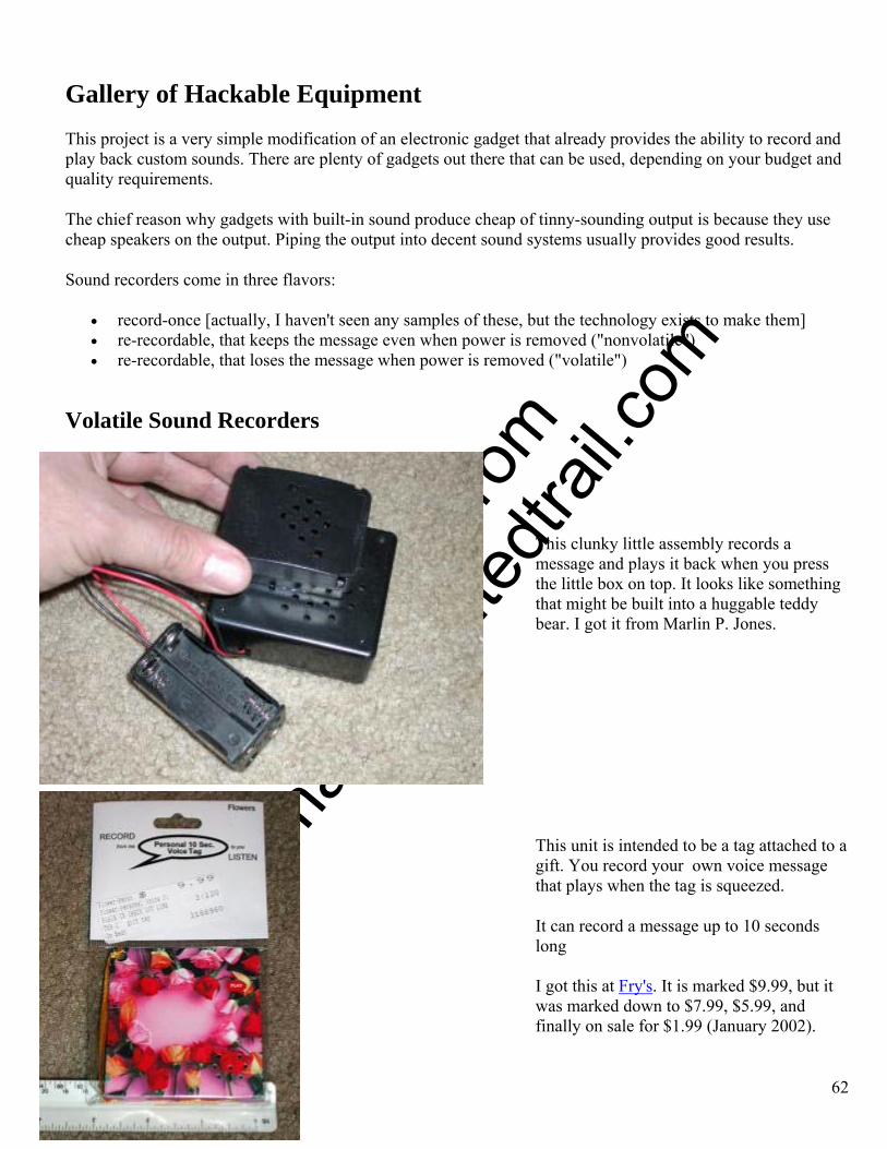
O
btaine
d fro
m
Omarsh
aunte
dtrail
.com
Gallery of Hackable Equipment This project is a very simple modification of an electronic gadget that already provides the ability to record and play back custom sounds. There are plenty of gadgets out there that can be used, depending on your budget and quality requirements.
The chief reason why gadgets with built-in sound produce cheap of tinny-sounding output is because they use cheap speakers on the output. Piping the output into decent sound systems usually provides good results.
Sound recorders come in three flavors:
• record-once [actually, I haven't seen any samples of these, but the technology exists to make them] • re-recordable, that keeps the message even when power is removed ("nonvolatile") • re-recordable, that loses the message when power is removed ("volatile")
Volatile Sound Recorders This clunky little assembly records a message and plays it back when you press the little box on top. It looks like something that might be built into a huggable teddy bear. I got it from Marlin P. Jones.
This unit is intended to be a tag attached to a gift. You record your own voice message that plays when the tag is squeezed.
It can record a message up to 10 seconds long
I got this at Fry's. It is marked $9.99, but it was marked down to $7.99, $5.99, and finally on sale for $1.99 (January 2002).
62
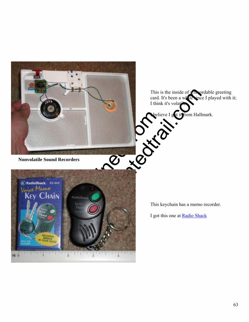
O
btaine
d fro
m
Omarsh
aunte
dtrail
.com
This is the inside of a recordable greeting card. It's been a while since I played with it; I think it's volatile.
I believe I got it from Hallmark.
Nonvolatile Sound Recorders
This keychain has a memo recorder.
I got this one at Radio Shack
63

O
btaine
d fro
m
Omarsh
aunte
dtrail
.com
This is prewired digital sound recorder from Radio Shack.
It can record a message up to 20 seconds long
Assembly The procedure is actually quite straightforward:
• Open up the gadget. • Find out where the "play" switch is attached. • Solder wires across the "play" switch and run them out to your triggering device. • Find out where the sound comes out (the "loudspeaker"). • Solder wires across the "speaker" and run them out to whatever device uses the sounds. This can be a set
of amplified speakers, a stereo, or mixer for more complex sound system. This project is simple because the gadget is already built. All you are doing is tapping into it. If you used a volatile sound recorder, you will need to re-record your sound every time you get ready to use it. Here is the setup we used for the sound of giant spider in our year 2000 haunt:
The Radio Shack recordable sound board is in the center. The trigger relay is lower right with the X-10 module just above it. The wire from the sound board terminates in a 1/8" socket that connects to the amplified speakers.
64
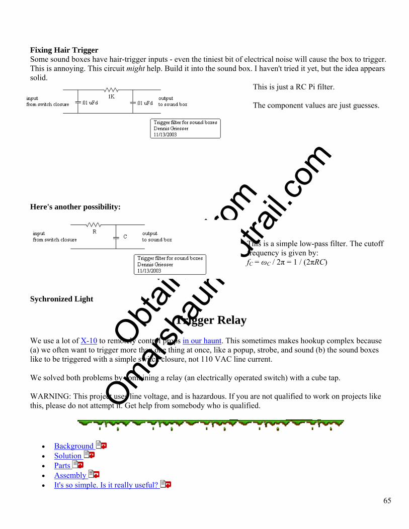
O
btaine
d fro
m
Omarsh
aunte
dtrail
.com
Fixing Hair Trigger Some sound boxes have hair-trigger inputs - even the tiniest bit of electrical noise will cause the box to trigger. This is annoying. This circuit might help. Build it into the sound box. I haven't tried it yet, but the idea appears solid.
This is just a RC Pi filter.
The component values are just guesses.
Here's another possibility:
This is a simple low-pass filter. The cutoff frequency is given by: fC = ωC / 2π = 1 / (2πRC)
Sychronized Light
Trigger Relay We use a lot of X-10 to remotely control props in our haunt. This sometimes makes hookup complex because (a) we often want to trigger more than one thing at once, like a popup, strobe, and sound (b) the sound boxes like to be triggered with a simple switch closure, not 110 VAC line current.
We solved both problems by combining a relay (an electrically operated switch) with a cube tap.
WARNING: This project uses line voltage, and is hazardous. If you are not qualified to work on projects like this, please do not attempt it. Get help from somebody who is qualified.
• Background • Solution • Parts • Assembly • It's so simple. Is it really useful?
65
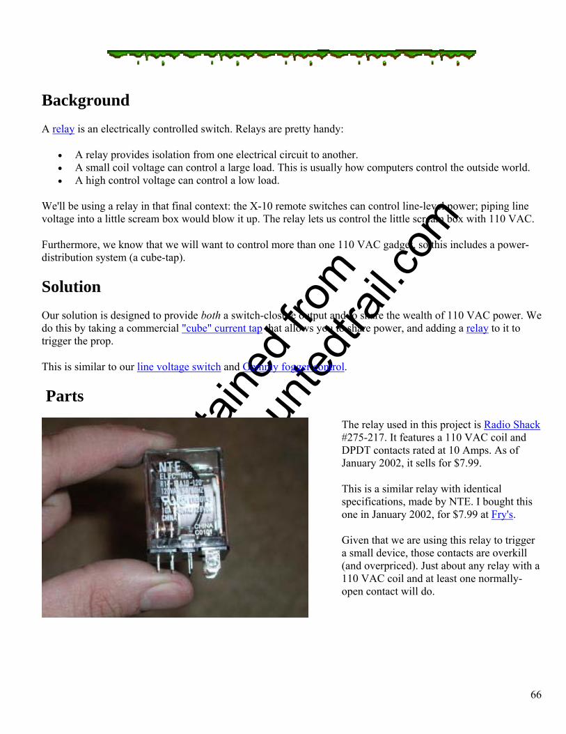
O
btaine
d fro
m
Omarsh
aunte
dtrail
.com
Background A relay is an electrically controlled switch. Relays are pretty handy:
• A relay provides isolation from one electrical circuit to another. • A small coil voltage can control a large load. This is usually how computers control the outside world. • A high control voltage can control a low load.
We'll be using a relay in that final context: the X-10 remote switches can control line-level power; piping line voltage into a little scream box would blow it up. The relay lets us control the little scream box with 110 VAC.
Furthermore, we know that we will want to control more than one 110 VAC gadget, so this includes a power-distribution system (a cube-tap).
Solution Our solution is designed to provide both a switch-closure output and to share the wealth of 110 VAC power. We do this by taking a commercial "cube" current tap that allows you to share power, and adding a relay to it to trigger the prop.
This is similar to our line voltage switch and Gemmy fogger control.
Parts The relay used in this project is Radio Shack #275-217. It features a 110 VAC coil and DPDT contacts rated at 10 Amps. As of January 2002, it sells for $7.99.
This is a similar relay with identical specifications, made by NTE. I bought this one in January 2002, for $7.99 at Fry's.
Given that we are using this relay to trigger a small device, those contacts are overkill (and overpriced). Just about any relay with a 110 VAC coil and at least one normally-open contact will do.
66
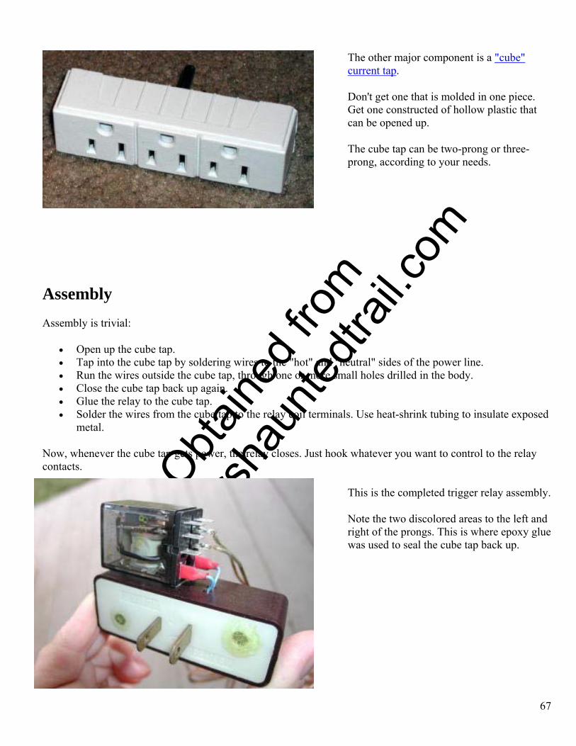
O
btaine
d fro
m
Omarsh
aunte
dtrail
.com
The other major component is a "cube" current tap.
Don't get one that is molded in one piece. Get one constructed of hollow plastic that can be opened up.
The cube tap can be two-prong or three-prong, according to your needs.
Assembly Assembly is trivial:
• Open up the cube tap. • Tap into the cube tap by soldering wires to the "hot" and "neutral" sides of the power line. • Run the wires outside the cube tap, through one or more small holes drilled in the body. • Close the cube tap back up again. • Glue the relay to the cube tap. • Solder the wires from the cube tap to the relay coil terminals. Use heat-shrink tubing to insulate exposed
metal.
Now, whenever the cube tap gets power, the relay closes. Just hook whatever you want to control to the relay contacts.
This is the completed trigger relay assembly.
Note the two discolored areas to the left and right of the prongs. This is where epoxy glue was used to seal the cube tap back up.
67

O
btaine
d fro
m
Omarsh
aunte
dtrail
.com
It's so simple. Is it really useful? Actually, it is.
We use one for our popup skeleton. The relay output triggers a canned scream box. A strobe, amplified speakers, and HAM all plug into the power cube. We just have to hit the trigger relay assembly with 110 VAC, and everything goes off at once.
We do the same thing with our pumpkin popup.
The giant spider gets slightly different treatment in that her amplified speakers are plugged into an unswitched outlet so that she continues to make noise when the power is cut and she moves down.
Amplified Speakers We have a big, honking sound system for the overall atmosphere. But we have "spot sound" associated with several props, such as the scream box that is triggered when the popup skeleton activates.
Each of these spot sounds uses a sound source, like a portable CD player, and a set of self-powered speakers. This allows us to crank the sound level of ueach prop up and down, and aim the speakers in the direction of the TOTs.
Some time ago, I thought it reasonable to build small dedicated amplifiers for each prop that required spot sound. I have come completely around on this subject: small sound systems are an exercise in purchasing, not manufacture. This is because small sound systems, usually intended for use with computers, are so inexpensive nowadays, it's scary!
For just a few bucks, you get amplifier, volume control, speaker(s), and some sort of power (either a plug for the wall, or a compartment for batteries).
• Inland • RadioShack
68
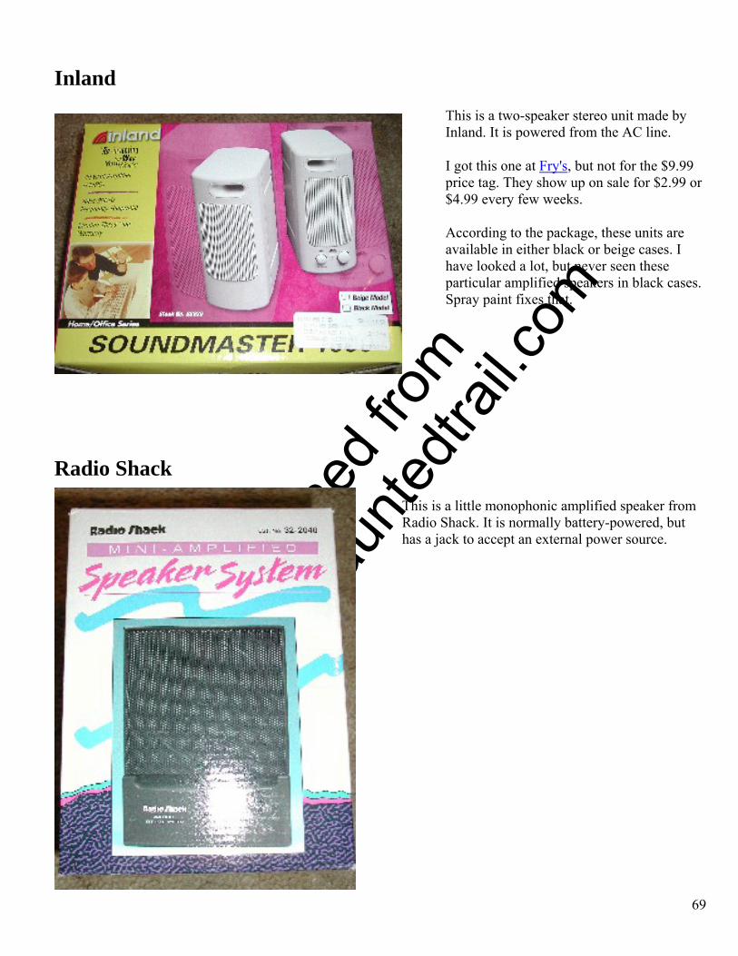
O
btaine
d fro
m
Omarsh
aunte
dtrail
.com
Inland This is a two-speaker stereo unit made by Inland. It is powered from the AC line.
I got this one at Fry's, but not for the $9.99 price tag. They show up on sale for $2.99 or $4.99 every few weeks.
According to the package, these units are available in either black or beige cases. I have looked a lot, but never seen these particular amplified speakers in black cases. Spray paint fixes that.
Radio Shack This is a little monophonic amplified speaker from Radio Shack. It is normally battery-powered, but has a jack to accept an external power source.
69
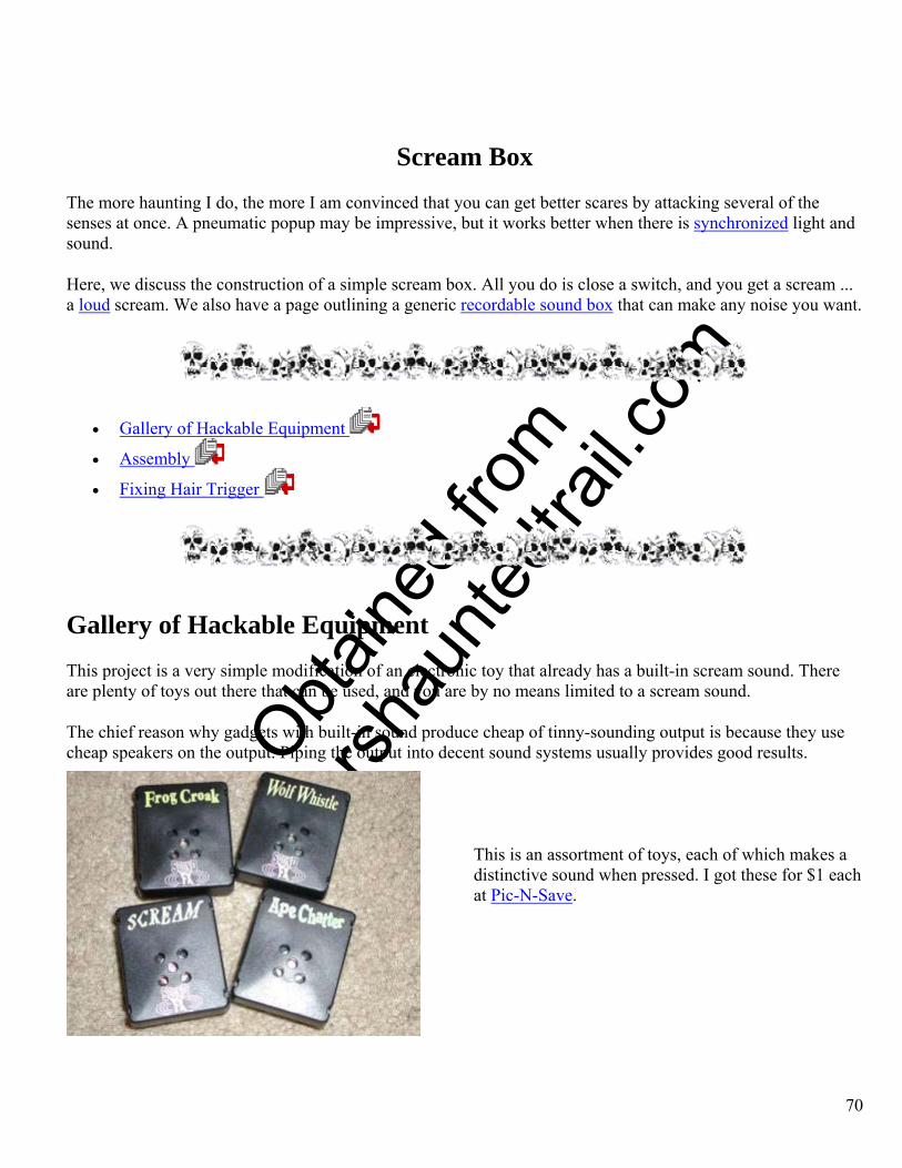
O
btaine
d fro
m
Omarsh
aunte
dtrail
.com
Scream Box The more haunting I do, the more I am convinced that you can get better scares by attacking several of the senses at once. A pneumatic popup may be impressive, but it works better when there is synchronized light and sound.
Here, we discuss the construction of a simple scream box. All you do is close a switch, and you get a scream ... a loud scream. We also have a page outlining a generic recordable sound box that can make any noise you want.
• Gallery of Hackable Equipment
• Assembly
• Fixing Hair Trigger
Gallery of Hackable Equipment This project is a very simple modification of an electronic toy that already has a built-in scream sound. There are plenty of toys out there that can be used, and you are by no means limited to a scream sound.
The chief reason why gadgets with built-in sound produce cheap of tinny-sounding output is because they use cheap speakers on the output. Piping the output into decent sound systems usually provides good results.
This is an assortment of toys, each of which makes a
distinctive sound when pressed. I got these for $1 each at Pic-N-Save.
70
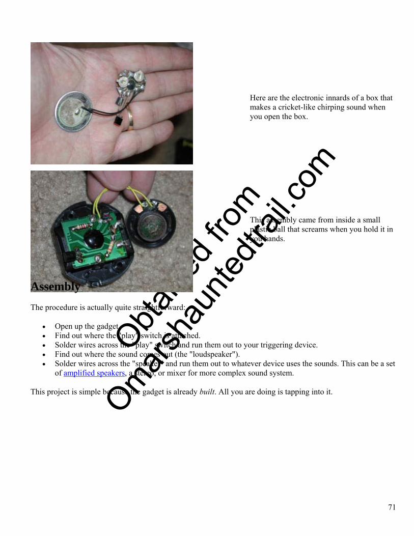
O
btaine
d fro
m
Omarsh
aunte
dtrail
.com
Here are the electronic innards of a box that makes a cricket-like chirping sound when you open the box.
This assembly came from inside a small plastic ball that screams when you hold it in you hands.
Assembly The procedure is actually quite straightforward:
• Open up the gadget. • Find out where the "play" switch is attached. • Solder wires across the "play" switch and run them out to your triggering device. • Find out where the sound comes out (the "loudspeaker"). • Solder wires across the "speaker" and run them out to whatever device uses the sounds. This can be a set
of amplified speakers, a stereo, or mixer for more complex sound system.
This project is simple because the gadget is already built. All you are doing is tapping into it.
71
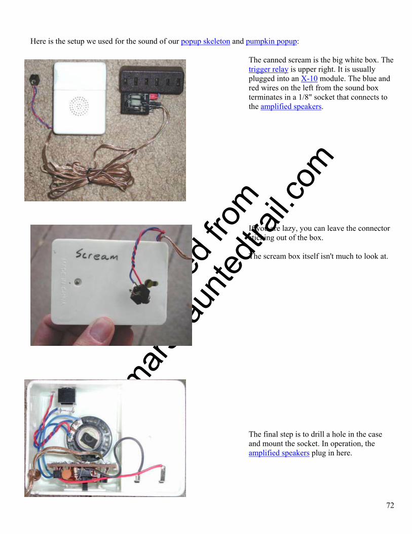
O
btaine
d fro
m
Omarsh
aunte
dtrail
.com
Here is the setup we used for the sound of our popup skeleton and pumpkin popup:
The canned scream is the big white box. The trigger relay is upper right. It is usually plugged into an X-10 module. The blue and red wires on the left from the sound box terminates in a 1/8" socket that connects to the amplified speakers.
If you are lazy, you can leave the connector sticking out of the box. The scream box itself isn't much to look at.
The final step is to drill a hole in the case and mount the socket. In operation, the amplified speakers plug in here.
72
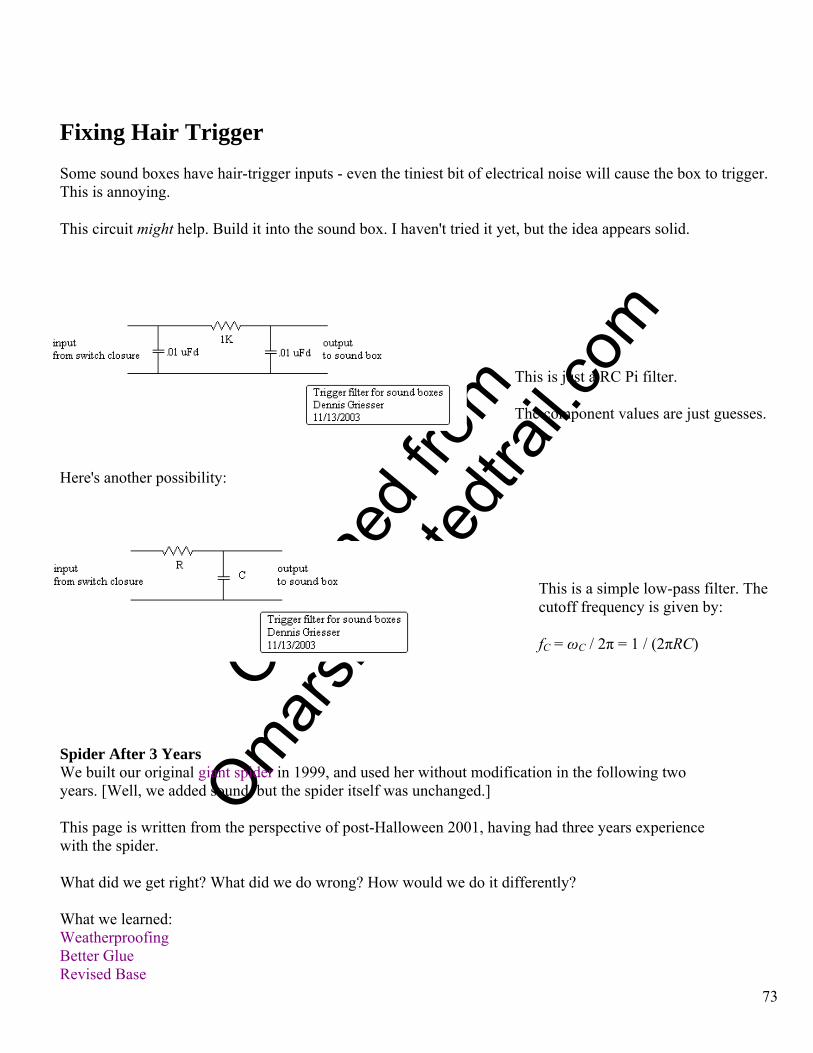
O
btaine
d fro
m
Omarsh
aunte
dtrail
.com
Fixing Hair Trigger Some sound boxes have hair-trigger inputs - even the tiniest bit of electrical noise will cause the box to trigger. This is annoying.
This circuit might help. Build it into the sound box. I haven't tried it yet, but the idea appears solid.
73
This is just a RC Pi filter.
The component values are just guesses.
Here's another possibility:
This is a simple low-pass filter. The cutoff frequency is given by:
fC = ωC / 2π = 1 / (2πRC) Spider After 3 Years We built our original giant spider in 1999, and used her without modification in the following two years. [Well, we added sound, but the spider itself was unchanged.] This page is written from the perspective of post-Halloween 2001, having had three years experience with the spider. What did we get right? What did we do wrong? How would we do it differently? What we learned: Weatherproofing Better Glue Revised Base
O
btaine
d fro
m
Omarsh
aunte
dtrail
.com
74
Related Projects Weatherproofing The original animated rooftop spider was never designed for harsh weather conditions. We live in southern California, and the weather is usually mild. So we knowingly cut corners, making up for it by only putting the spider up at the last minute, after consulting the forecast. In 2001, the spider got rained on, showing that you can only get by for so long. Even if weather were not much of a factor, it's better to be safe than sorry. We really should have built her to be much more water-resistant. That means: Use outdoor plywood, not just scraps of whatever happened to be around. Wet cloth is heavy. Consider some other form of covering. Use better glue to attach the rug scraps that cushion the roof. Better Glue In the context of "Weatherproofing", we suggested using better glue to attach the rug scraps that cushion the roof. Actually, that item isn't just rain-related. Whenever we needed to attach carpet scraps to plywood, we used hot glue. Even before the rain, the carpet was showing signs of coming off in our third year of use. We probably should have used a construction adhesive, like Liquid Nails, or even real carpet glue. Revised Base We have some issues with the base of the spider, mostly stemming from the design. The spider mechanism and base were built and tested on level ground. We always assumed that if she could rear up on the ground, and she could be mounted on the roof, she could rear up on the roof. This was true, but we forgot that, once mounted on the roof, the resting state would be pointing downhill. This places stress on the two upright "legs". They don't appear ready to break, but they make us nervous. The base should have taken the roof pitch into account. This would reduce stress on the uprights. And perhaps we need more uprights, or to strengthen the existing ones with a metal pipe inside. In year three, we also noted that the spider is not as energetic and responsive as she once was. It took more air pressure to activate her than in the past. After examining the structure, we determined that it's not an issue of dirt or wear in the bored-out PVC joints. Perhaps she would benefit in having the upright "legs" spaced a bit further apart. And having the pneumatic cylinder offset from the center line might be torquing things. I don't remember exactly why the air cylinder was orivinally offset that way.

O
btaine
d fro
m
Omarsh
aunte
dtrail
.com
Ideally, we would rebuild the base before the next use of the spider.
For 2002, we ended up making some simple changes to the existing base, in order to strengthen the uprights.
For 2002, we also replaced the modified screen door closer with a commercial pneumatic cylinder.
75