gibbscam 13.0: what's new - fructus data...
TRANSCRIPT
GibbsCAM 13
What’s New in GibbsCAM 13
3D Systems, Inc.Modified: Monday, February 25, 2019 12:01 PM
Proprietary NoticeThis document contains proprietary information of 3D Systems, Inc. (“3DS”) and is to be used onlypursuant to and in conjunction with the license granted to the licensee with respect to theaccompanying licensed software from 3DS. Except as expressly permitted in the license, no part ofthis document may be reproduced, transmitted, transcribed, stored in a retrieval system, ortranslated into any language or computer language, in any form or by any means, electronic,magnetic, optical, chemical, manual or otherwise, without the prior expressed written permissionfrom 3DS or a duly authorized representative thereof.
It is strongly advised that users carefully review the license in order to understand the rights andobligations related to this licensed software and the accompanying documentation.
Use of the computer software and the user documentation has been provided pursuant to a 3DSlicensing agreement.
Copyright © 1993 – 2019 3DS. All rights reserved. The Gibbs and GibbsCAM logos, GibbsCAM,Gibbs, Virtual Gibbs, and “Powerfully Simple. Simply Powerful.” are either trademark (s) orregistered trademark(s) of 3DS in the United States and/or other countries. All other trademark(s)belong to their respective owners.
Portions of this software and related documentation are copyrighted by and are the property of Siemens ProductLifecycleManagement Software Inc.
Microsoft, Windows, and theWindows logo are trademarks, or registered trademarksof Microsoft Corporation in theUnited Statesand/or other countries.
ContainsPTC Creo GRANITE Interoperability Kernel by PTC Inc. All PTC logos are used under license from PTCInc., Needham,MA, USA. 3DS is an independent Software Provider.
Portionsof this software © 1994–2019 Spatial Technology Inc. / Dassault Systèmes / SpatialCorp.
Portionsof this software © 2001–2019GeometricSoftware SolutionsCo. Ltd.
ContainsAutodesk®RealDWGbyAutodesk, Inc., © 1998-2019 Autodesk, Inc. All rights reserved.
DMGMORIModels provided in conjunction with GibbsCAM© 2007–2019 DMGMoriSeikiCo., Ltd.
Contains VoluMill™ and VoluTurn™ by Celeritive Technologies, Inc. © 2007–2019 Celeritive Technologies, Inc. Allrights reserved.
This Product includes software developed by the OpenSSL Project for use in the OpenSSL Toolkit(http://www.openssl.org/). ThisProduct includes cryptographic software written byEricYoung ([email protected]).
Portionsof this software ©MachineWorksLtd.
Portions of this software and related documentation are copyrighted by and are the property of Electronic DataSystemsCorporation.
Other portionsof GibbsCAM are licensed fromGibbsCAM licensors, whichmaynot be listed here.
3
Contents
WELCOME TO GIBBSCAM 13 6General Information 6Functional Enhancements 6
Improved Workflow, Common Function, and GUI 6Tooling and Toolholders 7Turning and Mill 75-Axis 7
Enhancements That Require Post Modifications 8
Workflow, Common Function, User Interface 9Operation Tile Stacking 9
Appearance and Behavior of Op Tile Stacks 10WhichProcess Icon Is Displayed? 10
Opening, Closing, and Scrolling a Stack of Op Tiles 10About Manual Stacks 11Dragging and Dropping 11
G-Code Editor 11Preferences 12
Geometry: Fillet-Chamfer Dialog 13Advanced Approach and Retract 14
Interface 14Customization 14
Keyboard Shortcut List 15Command Containers 16
Profiler: Slice Spun Body for AnyCS 17Miscellaneous 18
File > Open > All Files 18Bulk Handling of WGs and CSes 19Status Bar Extensions 19
Plug-Ins onStatus Bar 20
Accelerated Performance 20Keyboard Shortcut List 21
Tooling 22Center Drills: FormsA, B, and R 22Toolholders 23
ATC holder library 23
Turning 24Eccentric and Elliptical Turning 24

4
Module Dependencies 26Chip Breaking 27Bar Chamfering 27
Mill 29FaceMilling 29
Roll-In Entry 29Round Corners 30Cut Above Stock 31Improvements to Shape Option 31Fixture Avoidance 32
Broaching 33Broaching: Overview 33Broaching Processes 33
Linear Broaching 33Rotary Broaching 34
Broaching Tools 34Linear Broaching Tools 35Rotary Broaching Tools 36
5-Axis 383D CRC (3D Cutter RadiusCompensation) 38
To enable 3D CRC 38
What Is 3D CRC? 38Applications 393D CRC Support 395-Axis Operation Programming Tips 39
GeodesicMachining in 5-Axis 40New Calculation Type: Geodesic Machining 40Background 40Geodesic 40Features of Geodesic 40
Deburring in 5-Axis 41New Calculation Type: Deburring 41
Miscellaneous 5-Axis Enhancements 42General and Surface Path 42Triangle Mesh and Wireframe 43Swarf Machining 44Port Machining 44
5-Axis Tool Support 45Advanced Barrel Mills 45
WORTH ANOTHER LOOK 46Clearance Volume 46Simple and Powerful Form Tool Definition 47

5
Did You Know Intermediate Tooling CanDo This, Too? 48
Welcome to GibbsCAM13
6
Welcome to GibbsCAM 13Themain themes of this release are: Improved turning functionality (also affectingMTM andMill/Turn); support for new tools and toolholders and a new set of processes (Broaching);improvements to 2D and 2½D Mill, and the addition of Op Tile Stacks.
This guide is an overview of all important items that have been added or changed. Its descriptionsare still subject to change and amplification.
For details on UI changes and enhancements, see the CommonReference andGetting Startedguides. For details on product-specific changes and enhancements, see the product-specific userguides: Broaching, Reporter, Mill, Turning, 5-Axis, and so forth.
Please Note: The product option formerly known as Lathe is now called Turning.
General Information• GibbsCAM 13 supports all OS platforms supported byGibbsCAM 12 and adds no new OS
platforms.
• GibbsCAM 13 supports a broad range of new tools and toolholders. These are described indetail.
• Data translators byDatakit are no longer supported. They have been replaced by thecorresponding translators by Spatial (a unit of Dassault Systèmes, and developer of the3D ACIS kernel). TheGranite library is updated, and is used for PTC Creo Parametric only.
• GibbsCAM 13 product options 5-Axis, MultiBlade, and Port Machining are updated to useimprovedmulti-axis technology libraries. Specific functional enhancements are detailed below.
• The Adveon Tool Library, fromSandvik Coromant, will be replaced byCoroPlus, whichprovides a superset of the same functionality.
Functional Enhancements
ImprovedWorkflow, Common Function, and GUI
Operation Tile stacking allows operation tiles to be grouped together in a folder-like stack reducingclutter and increasing quick access.
Broaching. A new set of processes and tools, documented in a new user guide.
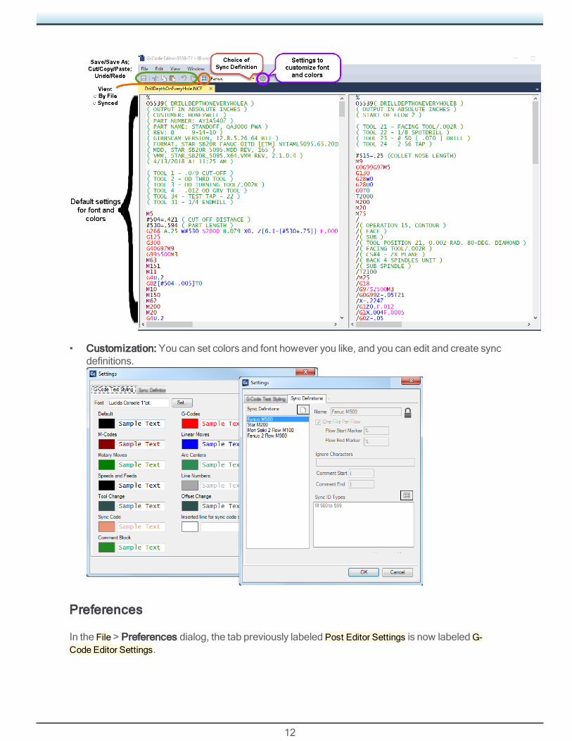
G-Code editor provides customizable color coding, cut/copy/paste/undo, multi-pane for subfilesand/or sync definitions for multi-flow, andmany other function points.
Welcome to GibbsCAM13
7
Geometry Fillet-Chamfer dialog now provides aMultiple Circle button, , for rapidly filletingor chamfering selections of differing radii without having to reopen the dialog.
Profiler. Slice Spun Body mode is no longer confined to just the primary CS (CS1). It nowproduces spun outline around the horizontal axis of the active [non-turning] CS.
Status Bar extensions. The bar below the workspace now providesmore information.
Filterless File Opener. The File > Open dialog can now be configured to show all files, rather thanrequiring you to specify a filetype.
Bulk Management of WG and CS lists. You can now perform bulk operations on workgroups andcoordinate systems like Show All WGs or Delete All Hidden CSes.
Customization. You can now create containers of commands and you can view and print the list ofkeyboard shortcuts.
Performance. A new checkbox in the File > Preferences dialog, Accelerated Process Loading,substantially reduces the time required to load large process list files (at the cost of increasedmemory usage).
Tooling and Toolholders
ATC holder library.
Intermediate Tooling now provides some streamlined controls for locating toolblockswithin alibrary.
Center Drilling now encompasses true Form B and Form R aswell as Form A.
Mill Tools now provide Tangent Mill (oval-form) and Tapered Barrel Mill.
Turning and Mill
Interpolation turning, eccentric turning, and elliptical turning. (These are sometimes also knownas "C-axis turning" and "orbital turning".)
Chip breaker cycle for roughing
Automatic bar chamfering.
Advanced approach/retract lets you define a custom path for tools' approach or retract.
Face milling improvements: Roll-in entry, round corners, cut above stock, increased shapecapabilities, and fixture avoidance.
5-Axis
3D CRC.
Updated multi-axis libraries.
New machining strategy: Deburring.
Welcome to GibbsCAM13
8
New machining strategy: Geodesic.
Enhancements That Require Post ModificationsAs always, no post is needed for you to exercise the user interface and generate toolpath. But tooutput correctly in GibbsCAM 13, the following enhancements require post modifications:
• Lathe Roughing: Chip Breaker requires an easy change to pre-13 posts.
• Swiss: Auto Bar Chamfer requires an easy change to pre-13 posts.
• 5-Axis 3D CRC appends new toolpath data to the operation, and so small post changes arerequired, such asOutput3DCRCNormal, 3DCRCNormal*#, and various form edits. Note thatonly explicit 3D CRC is supported at this time.
• Broaching, whether linear or rotary, requires a post change.
• Advanced Approach/Retract requires a UKM-style post.
• Advanced turning (interpolation turning, eccentric turning, elliptical turning) requires anextensive post change.
9
Workflow, Common Function, User InterfaceGibbsCAM 13 provides simple and powerful new ways to organize and display information and tospecify tricky tool moveswith a few clicks:
• “Operation Tile Stacking ” on page 9
• “G-Code Editor” on page 11
• “Geometry: Fillet-Chamfer Dialog” on page 13
• “Customization” on page 14
• “Advanced Approach and Retract” on page 14
• “Profiler: Slice Spun Body for AnyCS” on page 17
• “Miscellaneous” on page 18
An overview of new function follows below. For details, see the CommonReference guide.
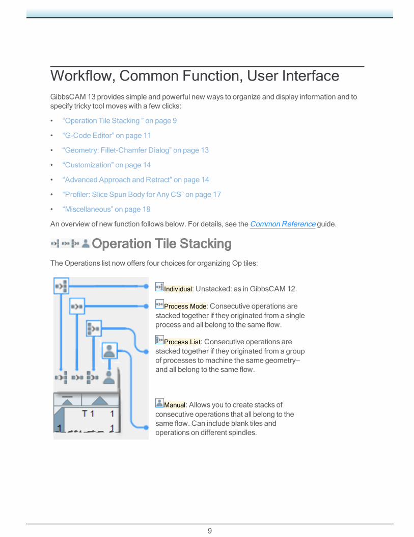
Operation Tile StackingTheOperations list now offers four choices for organizing Op tiles:
Individual: Unstacked: as in GibbsCAM 12.
Process Mode: Consecutive operations arestacked together if they originated from a singleprocess and all belong to the same flow.
Process List: Consecutive operations arestacked together if they originated from a groupof processes tomachine the same geometry—and all belong to the same flow.
Manual: Allows you to create stacks ofconsecutive operations that all belong to thesame flow. Can include blank tiles andoperations on different spindles.
10
Appearance and Behavior of Op Tile Stacks
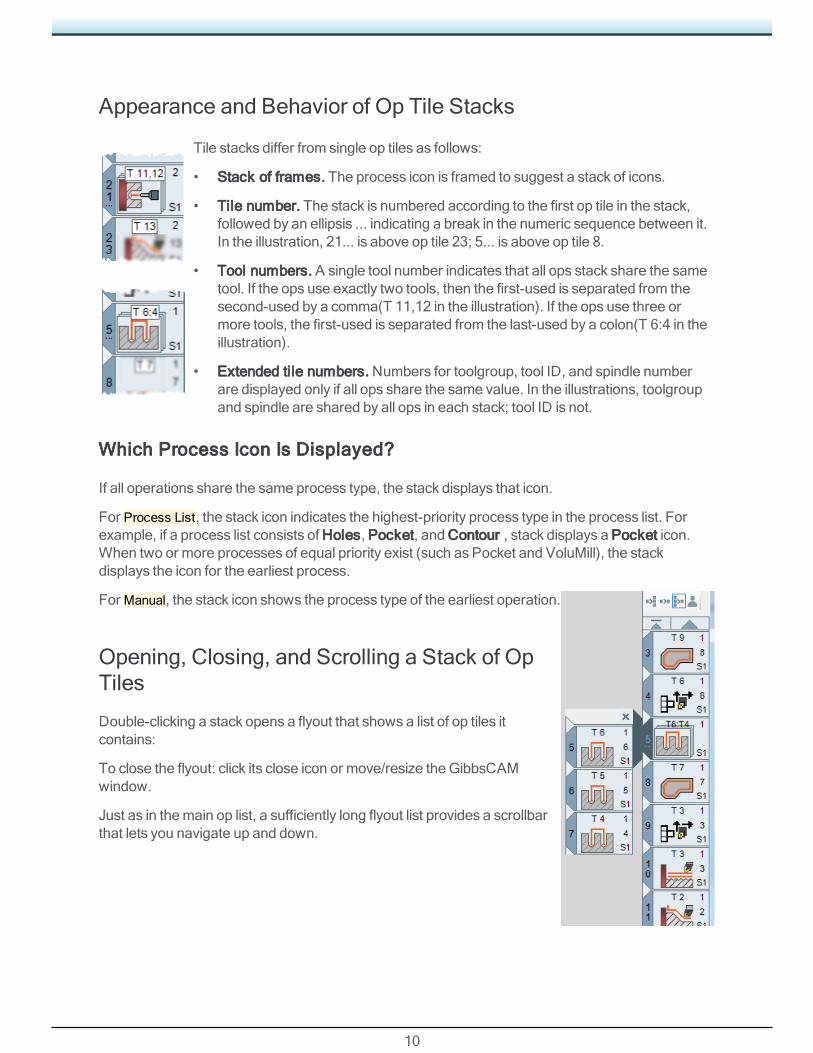
Tile stacks differ from single op tiles as follows:
• Stack of frames. The process icon is framed to suggest a stack of icons.
• Tile number. The stack is numbered according to the first op tile in the stack,followed by an ellipsis ... indicating a break in the numeric sequence between it.In the illustration, 21... is above op tile 23; 5... is above op tile 8.
• Tool numbers. A single tool number indicates that all ops stack share the sametool. If the ops use exactly two tools, then the first-used is separated from thesecond-used by a comma(T 11,12 in the illustration). If the ops use three ormore tools, the first-used is separated from the last-used by a colon(T 6:4 in theillustration).
• Extended tile numbers. Numbers for toolgroup, tool ID, and spindle numberare displayed only if all ops share the same value. In the illustrations, toolgroupand spindle are shared by all ops in each stack; tool ID is not.
Which Process Icon Is Displayed?
If all operations share the same process type, the stack displays that icon.
For Process List, the stack icon indicates the highest-priority process type in the process list. Forexample, if a process list consists of Holes, Pocket, and Contour , stack displays a Pocket icon.When two or more processes of equal priority exist (such as Pocket and VoluMill), the stackdisplays the icon for the earliest process.
ForManual, the stack icon shows the process type of the earliest operation.
Opening, Closing, and Scrolling a Stack of OpTiles
Double-clicking a stack opens a flyout that shows a list of op tiles itcontains:
To close the flyout: click its close icon or move/resize the GibbsCAMwindow.
Just as in themain op list, a sufficiently long flyout list provides a scrollbarthat lets you navigate up and down.

11
About Manual Stacks
ChoosingManual op tile stack display creates the following special conditions:
• The context-sensitive (right-mouse-click) menu offers two additional items:
▪ Create Stack Allows you to create amanual stack. ForManual only, a stack can consist ofone tile.
▪ Unstack Undoes themanual stack of the right-clicked item.
• The part "remembers" all manual stacks even when it is in a different mode. ReselectingManualwill restore the previousManual display state, unlessmanual stacks have been broken by otherop tile additions, moves, or deletions.
Dragging and Dropping
You can drag an entire stack and drop it anywhere in the op list or into another stack. When a stackflyout is open, you can drag tiles into or out of the stack. However:
• Dragging a tile into or out of the stackmay cause the stack to break into two stacks if the rulesfor that stack cannot all be kept.
• Dragging a stack into the flyout of another stackmight result in two or three stacks if the rules forthe target stack cannot all be kept.
• Dropping a stack onto a stack does nothing.
G-Code EditorAt GibbsCAM 13, the built-in G-Code editor provides significant new features, including:
• Editing and file capabilities, such asCut/Copy/Paste, Undo/Redo, and Save/Save As.
• Context colors that distinguish at a glance items like code, code labels, and parameters withinindividual G-codes andM-codes.
• The ability to edit multiple subs. Each sub occupies its own tab in the window.
• When editingmultiple flows, you can choose either independent scrolling, where each flow isindependent of all others, or synched scrolling, where eachG-code stream is padded asneeded so that separate flows remain aligned according to their syncs.
12
• Customization: You can set colors and font however you like, and you can edit and create syncdefinitions.
Preferences
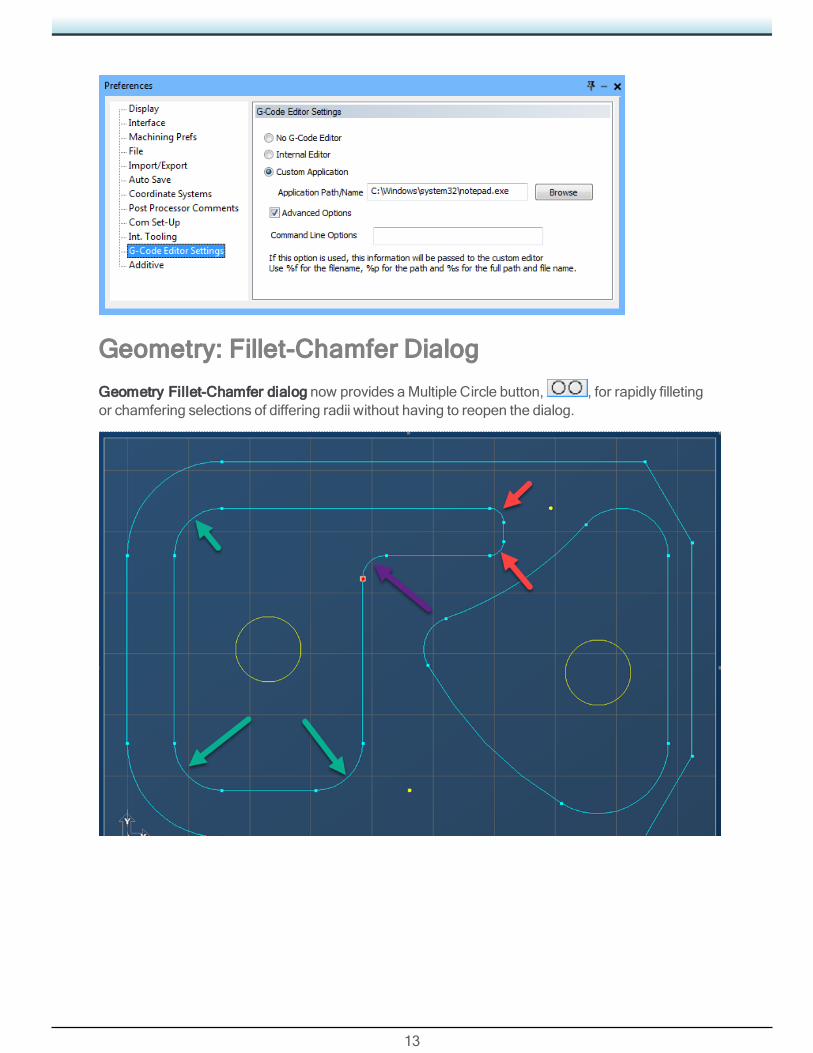
In the File > Preferences dialog, the tab previously labeled Post Editor Settings is now labeledG-Code Editor Settings.
13
Geometry: Fillet-Chamfer Dialog
Geometry Fillet-Chamfer dialog now provides aMultiple Circle button, , for rapidly filletingor chamfering selections of differing radii without having to reopen the dialog.

14
Advanced Approach and Retract
Please Note: This feature requires a post upgrade. To request a post upgrade, contact yourReseller or the Gibbs Post Department.
TheOperation Data dialog, summoned by right-clicking aMilling or Turning operation, now lets youspecify a custom path for tool approach and retract.
This allows you to determine tool locations to avoidinterference between tool and stock for suchoperations as back boring, milling with right-angleheads, and ID or OD turning.
Interface
The Advanced Approach Retract dialog lets youselect a custom approach and/or a custom retract.Or you can specify that the retract path reverses theapproach path.
When you click either of the Select buttons, a dialogprompts you to define a path by selecting it in theworkspace. Clicking Apply sets that path as thecustom approach or retract.
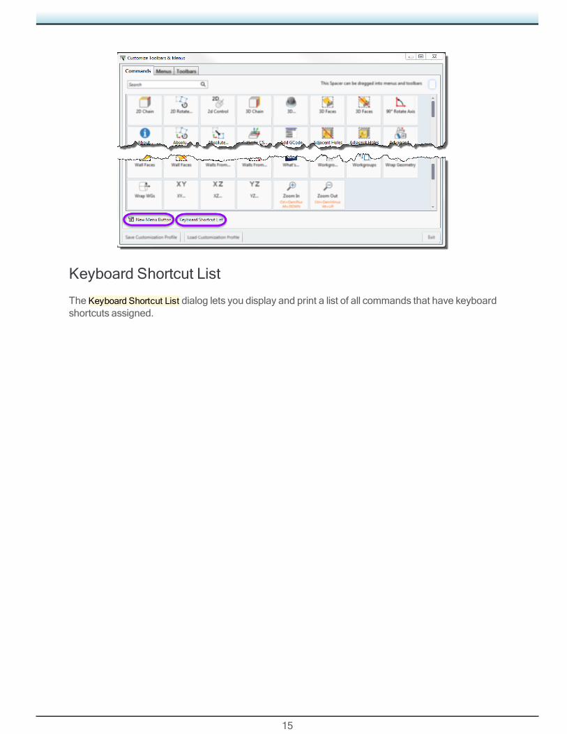
CustomizationIn the Customize Toolbars and Menus dialog, two new controls have been added to the bottom ofthe Commands tab:
15
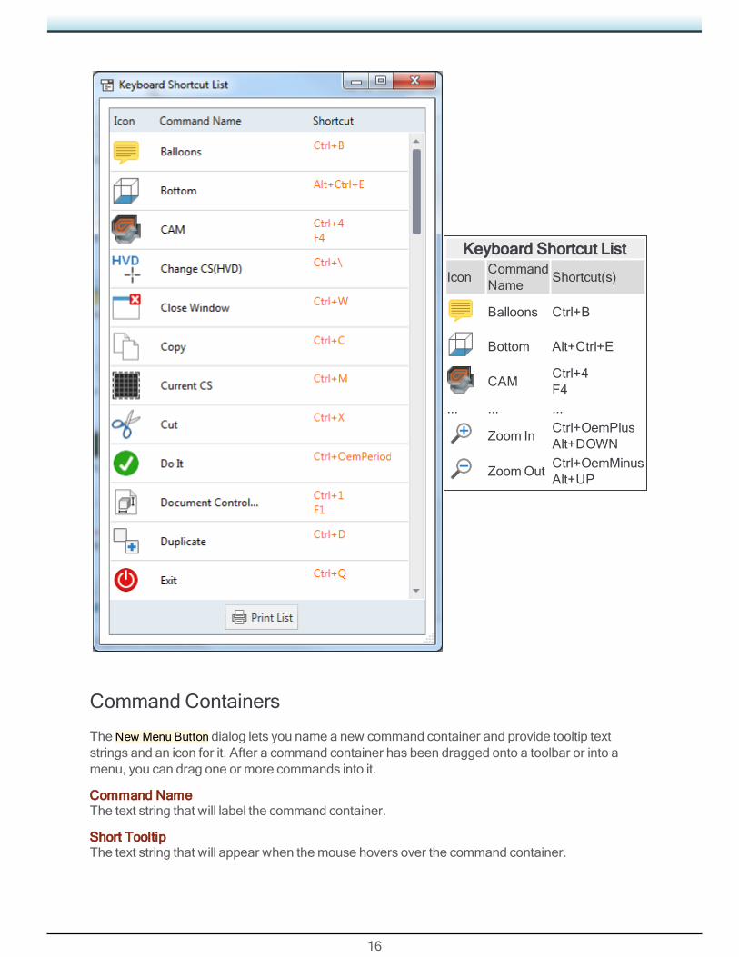
Keyboard Shortcut List
The Keyboard Shortcut List dialog lets you display and print a list of all commands that have keyboardshortcuts assigned.
16
Keyboard Shortcut List
IconCommandName
Shortcut(s)
Balloons Ctrl+B
Bottom Alt+Ctrl+E
CAMCtrl+4F4
... ... ...
Zoom InCtrl+OemPlusAlt+DOWN
ZoomOutCtrl+OemMinusAlt+UP
Command Containers
TheNew Menu Button dialog lets you name a new command container and provide tooltip textstrings and an icon for it. After a command container has been dragged onto a toolbar or into amenu, you can drag one or more commands into it.
Command NameThe text string that will label the command container.
Short TooltipThe text string that will appear when themouse hovers over the command container.

17
Long TooltipThe text string that will appear onmouseover if Balloons are turned on.
Icon
If you do not use the (Browse) button to navigate to and choose an *.icn file, then default icon will
be .
OK: Accept changes and close the dialog.
Cancel: Discard changes and close the dialog.
Profiler: Slice Spun Body for Any CSSlice Spun Bodymode is no longer confined to just the primary CS (CS1).
When used in a non-turning CS, Profiler now produces spun outline around the horizontal axis ofthe active CS, instead of changing to Slicemode.

18
Miscellaneous
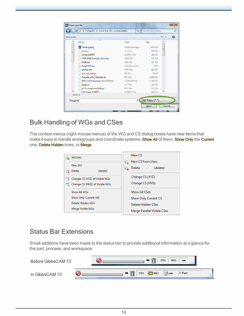
File > Open > All Files
In the File > Open dialog box, you can now specify All Files (*.*) to display all files of all filetypes inthe current folder.
19
Bulk Handling of WGs and CSes
The context menus (right-mousemenus) of theWG and CS dialog boxes have new items thatmake it easy to handle workgroups and coordinate systems: Show All of them, Show Only theCurrentone, Delete Hidden ones, orMerge.
Status Bar Extensions
Small additions have beenmade to the status bar to provide additional information at a glance forthe part, process, and workspace.
Before GibbsCAM 13
In GibbsCAM 13

20
Double-clicking any of the indicator items on the right — CS<n>=coordinate system,WG<n>=workgroup, units, or 1 Part / <n> Parts / TMS MultiPart — summons the dialog box for viewingor changing that item.
Plug-Ins on Status Bar
Some plug-ins, such as Show Position, can be registered so as to reside in the Status Bar. For theShow Position plug-in: Start the Right-click the titlebar and, on the context menu, select Install toTask Bar.
Accelerated Performance
A new Preferences setting significantly speeds up performance when loading tool lists, processlists. In the File > Preferences dialog, File tab, you can select the Accelerated Process Loadingcheckbox for increased performance (recommended), or leave it unselected to reducememoryusage.
21
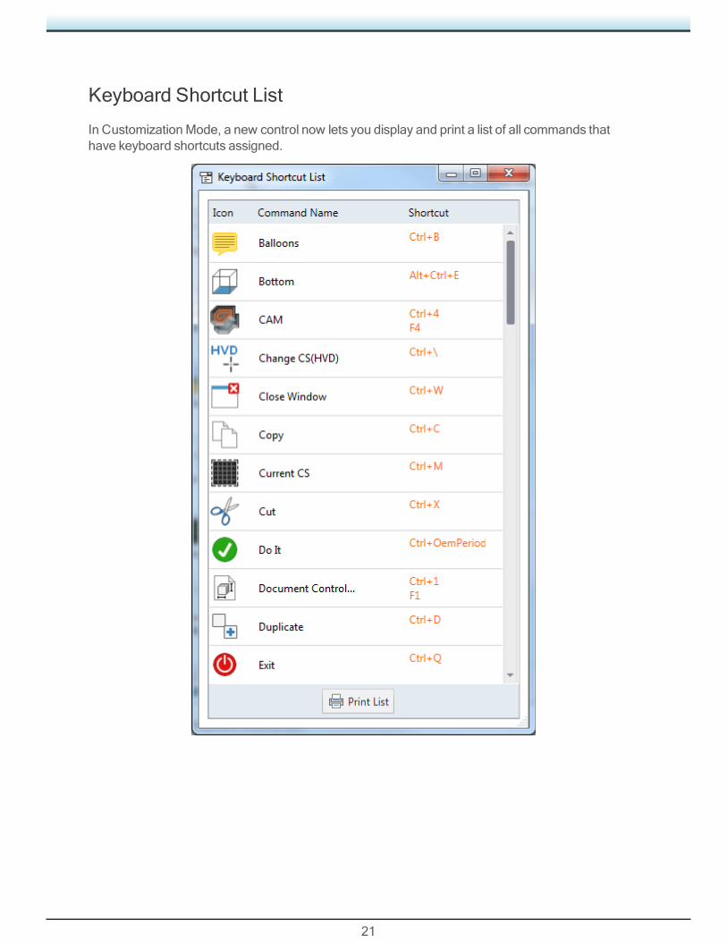
Keyboard Shortcut List
In CustomizationMode, a new control now lets you display and print a list of all commands thathave keyboard shortcuts assigned.

22
ToolingGibbsCAM 13 introduces new classes of tools and refinements to existing tools:
• Center Drills: FormsA, B, and R, below
• “Broaching Tools” on page 34
• “Toolholders” on page 23
An overview of new function follows below. For details, see the Broaching, CommonReference,Turning, andMill guides.
Center Drills: Forms A, B, and RPrior to GibbsCAM 13, center drills used the simple outlineillustrated on the right.
This is a Form A outline, even for Sizes whose names indicatedotherwise, such as b1/2 (inches) or b10 (mm).
In this release, GibbsCAM supports Form A center drills asbefore, but adds support for Form B and Form R aswell.
FormA: 10mm FormB: 10mm FormR: 10mm

23
Toolholders
ATC holder library

24
Turning
Please Note: The product option formerly known as Lathe is now called Turning.
GibbsCAM 13 brings several major enhancements to turning processes:
• “Eccentric and Elliptical Turning” on page 24
• “Chip Breaking” on page 27
• “Bar Chamfering” on page 27
An overview of new function follows below. For details, see the Turning guide.
Eccentric and Elliptical TurningGibbsCAM 13 expands existing turning capability:

25
Interpolation turningoccurs by interpolatingwith the X- and Y-axis in acircular direction androtating themachinespindle in time with therotational contour.
The circular movementcan increase or decreasein diameter to producefacing operations, or it canbe combined with the Z-axis to produce a bore orouter diameter.Eccentric turning, wherethe axis of rotation and thegeometric axis of theworkpiece are parallel butnot coincident, resulting inamachined piece that isoff-center.
For machineswithout on-control support forinterpolation turning,eccentric turningoperations requireGibbsCAM interpolationturning, and also requireClearance Volumeenabled in theMDD.
Elliptical turning, wherethe center of the ellipseitself follows thecircumference of a smallercenter, resulting in anellipse (oval).
Elliptical turningoperations requireGibbsCAM interpolationturning.
26
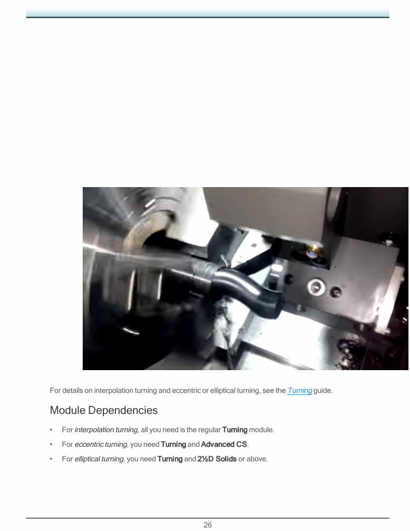
For details on interpolation turning and eccentric or elliptical turning, see the Turning guide.
Module Dependencies
• For interpolation turning, all you need is the regular Turningmodule.
• For eccentric turning, you need Turning and Advanced CS.
• For elliptical turning, you need Turning and 2½D Solids or above.

27
Chip BreakingWhat problem does it solve? Especially whenmachiningmaterial that is soft or spongy, chips cansometimes run to great length, interfering with themachining of the part.
Turning processesContour and Rough now provide a new capability: Chip Break, whose controlsgive you the ability to break off chips according to parameters you set.
The interface offers the following types of settings:
Pull OffWhen this is enabled, you can specify how far the tool will retractfrom the stock.
DwellWhen this is enabled, you can specify how many revolutions the tool wil stay in place before itcontinues to cut.
Chip LengthSpecify the length of chip to tolerate before Pull Off and/or Dwell occur. The length of chips that areremoved will remain constant even though the circumference of the stock diminishes (in anODprocess).
Please Note: A post change is required if your existing post does not support the output ofDwell Markers in toolpath. If you are unsure, contact your Reseller or the Gibbs PostDepartment to verify or request amodification.
Bar ChamferingWhat problem does it solve?When a Swiss-style turningmachine runs a roughing cycle, the partretracts into the guide bushing. A common problem is that a passmay leave a burr on the outside ofthe bar stock that can snag and cause problems for themachine.
28
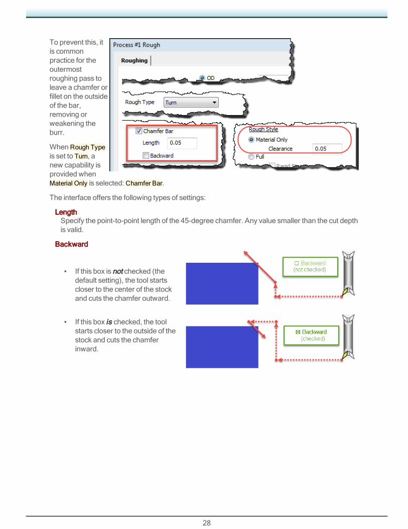
To prevent this, itis commonpractice for theoutermostroughing pass toleave a chamfer orfillet on the outsideof the bar,removing orweakening theburr.
WhenRough Typeis set to Turn, anew capability isprovided whenMaterial Only is selected: Chamfer Bar.
The interface offers the following types of settings:
LengthSpecify the point-to-point length of the 45-degree chamfer. Any value smaller than the cut depthis valid.
Backward
▪ If this box is not checked (thedefault setting), the tool startscloser to the center of the stockand cuts the chamfer outward.
▪ If this box is checked, the toolstarts closer to the outside of thestock and cuts the chamferinward.
29
MillGibbsCAM 13 brings several enhancements tomilling processes:
• “FaceMilling” on page 29
• tbd
An overview of new function follows below. For details, see theMill guide.
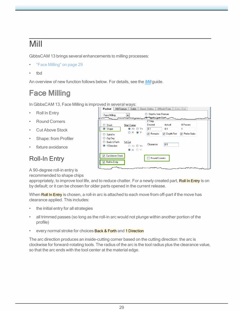
Face MillingIn GibbsCAM 13, FaceMilling is improved in several ways:
• Roll In Entry
• Round Corners
• Cut Above Stock
• Shape: fromProfiler
• fixture avoidance
Roll-In Entry
A 90-degree roll-in entry isrecommended to shape chipsappropriately, to improve tool life, and to reduce chatter. For a newly created part, Roll In Entry is onby default; or it can be chosen for older parts opened in the current release.
WhenRoll In Entry is chosen, a roll-in arc is attached to eachmove from off-part if themove hasclearance applied. This includes:
• the initial entry for all strategies
• all trimmed passes (so long as the roll-in arc would not plunge within another portion of theprofile)
• every normal stroke for choices Back & Forth and 1 Direction
The arc direction produces an inside-cutting corner based on the cutting direction: the arc isclockwise for forward-rotating tools. The radius of the arc is the tool radius plus the clearance value,so that the arc endswith the tool center at thematerial edge.

30
Round Corners
Round corners are recommended for facemilling while the tool is engaged, such as at every cornerfor strategies Spiral In or Zig Zag, which change direction while engaged. For a newly created part,Round Corners is on by default for those strategies; or it can be chosen for older parts opened in thecurrent release.
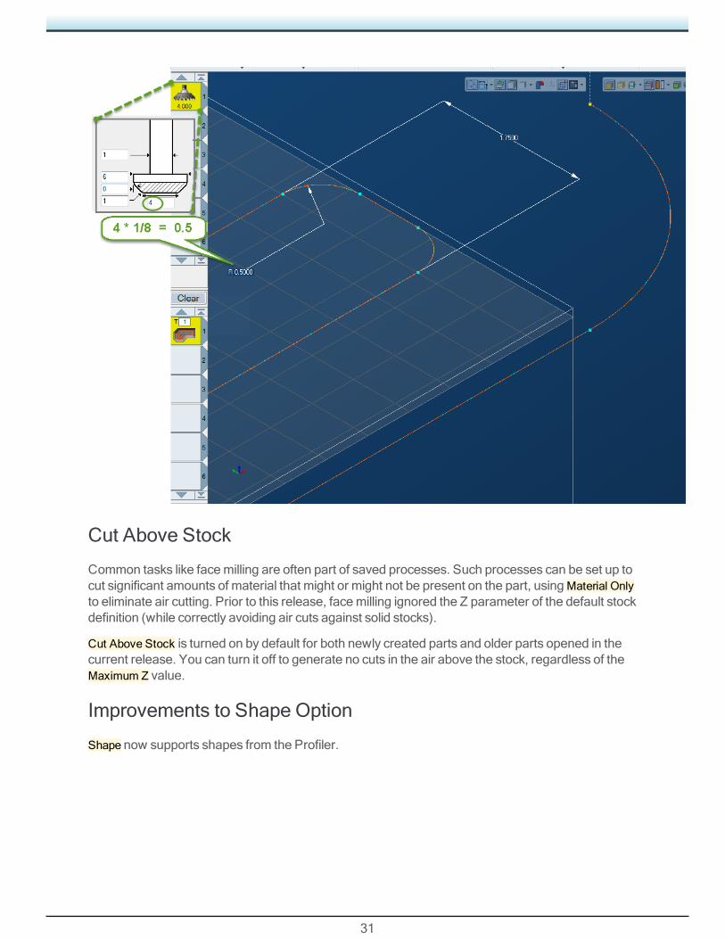
The radius for the corner arc is calculated as 1/8 (12.5%) of the tool diameter. The user mustensure an appropriate stepover size when using this option. In particular, strategy Spiral Inmightrequire smaller radii on passes very close to the center, and smaller radii might also be requirednear trimmed ends that are shorter than the normal round-corner radius. In such cases, use thelargest radius that fits.
31
Cut Above Stock
Common tasks like facemilling are often part of saved processes. Such processes can be set up tocut significant amounts of material that might or might not be present on the part, usingMaterial Onlyto eliminate air cutting. Prior to this release, facemilling ignored the Z parameter of the default stockdefinition (while correctly avoiding air cuts against solid stocks).
Cut Above Stock is turned on by default for both newly created parts and older parts opened in thecurrent release. You can turn it off to generate no cuts in the air above the stock, regardless of theMaximum Z value.
Improvements to Shape Option
Shape now supports shapes from the Profiler.

32
Fixture Avoidance
Unlike other machiningmethods, facemilling is not normally able to discontinue and resumecutting. Normalmechanisms for avoiding fixtures, such as cutting around the fixture, or retractingover it and plunging, are not desirable. To address this, avoidance behavior is based on theselected strategy:
• For Spiral In: the cut region is reduced to avoid the fixture without introducing concavities. Someareas of the part may be left unmachined.
• For Zig Zag: each cut terminateswhere it intersects a fixture and immediately transitions to thenext cut going the opposite direction. Neither cut will machine the part on the other side of thefixture.
• For Back & Forth and 1 Direction: each cut terminateswhere it intersects the fixture, and the cutwill not be resumed. Instead, the system immediately retracts and transitions to the next entrypoint.
For all strategies, use appropriate fixture clearance. If a part body is selected, collisionswithunselected parts of that body should be avoided just like collisionswith fixtures, consistent withordinary solid machining.

33
BroachingAt GibbsCAM 13, Broaching is newly provided as two new process types andmany new tools.
Licensing. If you have Turning, you automatically have Face Broaching. If you have Advanced CS,you automatically haveOriented Broaching.
Please Note: This feature requires a post upgrade. To request a post upgrade, contact yourReseller or the Gibbs Post Department.
• Broaching: Overview, below
• “Broaching Processes ” on page 33
• “Broaching Tools” on page 34
An overview of new function follows below. For details, see the Broaching guide.
Broaching: OverviewBroaching works best on softer materials, such as brass, bronze, aluminum, wood, and the like. Insome cases, the tool makes only a single pass, and so the process is very efficient.
Onmillingmachines, broaching an exterior face is very simple: Either the workpiece ismovedagainst a stationary broaching tool, or the workpiece is held stationary while the broaching tool ismoved against it. For internal broaching, such as keyway broaching, the workpiecemust alreadyhave a hole that allows the broaching tool to enter.
On turningmachines, a broaching tool requires a special toolholder that allows it to rotate in syncwith the workpiece. Different broaching tools are used for ID andOD broaching.
Broaching Processes
• Linear Broaching below
• “Rotary Broaching ” on page 34
Linear Broaching
In linear broaching, a broaching tool is run linearly along a surface of the workpiece to create a cut,often in repeated passes, but sometimes, for very soft materials, in a single pass.

34
Rotary Broaching
In rotary broaching, a broaching tool is held in a specialtoolholder that allows it to spin freely in contact with the spinningworkpiece, and holds the tool with a slightlymisaligned axis ofrotation so as to create a slight wobble. The tool is pressed intothe workpiece for interior broaching, or around the workpiece forexterior broaching.
Broaching ToolsGibbsCAM 13 supplies templates for fourteen broaching tools — seven for linear broaching andseven for rotary broaching.
Please Note: On turningmachines, a broaching tool requires a special toolholder that allowsit to rotate in syncwith the workpiece. Different broaching tools are used for ID andOD broaching.

35
Linear Broaching Tools
icons Name End View Side View Notes
Linear HexagonBroach
Linear KeywayBroach
Linear ChamferBroach

36
Linear CornerBroach
LinearHexalobularBroach
Linear 2D FormBroach
Linear 3D FormBroach
Rotary Broaching Tools
icons Name End View Side View Notes
Rotary HexagonBroach
Rotary DoubleHexagon Broach

37
Rotary RectangleBroach
RotaryHexalobularBroach
Rotary 2D FormBroach
Rotary 3D FormBroach
Rotary ExternalHexagon
38
5-AxisGibbsCAM 13 brings several major enhancements to 5-Axis, including:
• 3D CRC (3D Cutter RadiusCompensation)
• “GeodesicMachining in 5-Axis” on page 40
• “Deburring in 5-Axis” on page 41
• “Miscellaneous 5-Axis Enhancements” on page 42
• “5-Axis Tool Support” on page 45
An overview of new function follows below. For details, see the 5-Axis guide.
3D CRC (3D Cutter Radius Compensation)For 5-Axis and relatedmodules (MultiBlade and Port Machining), you can now use a 3D version ofCRC (cutter radius compensation).
Please Note: Because 3D CRC appends new toolpath data to the operation, a small postprocessor change is required.
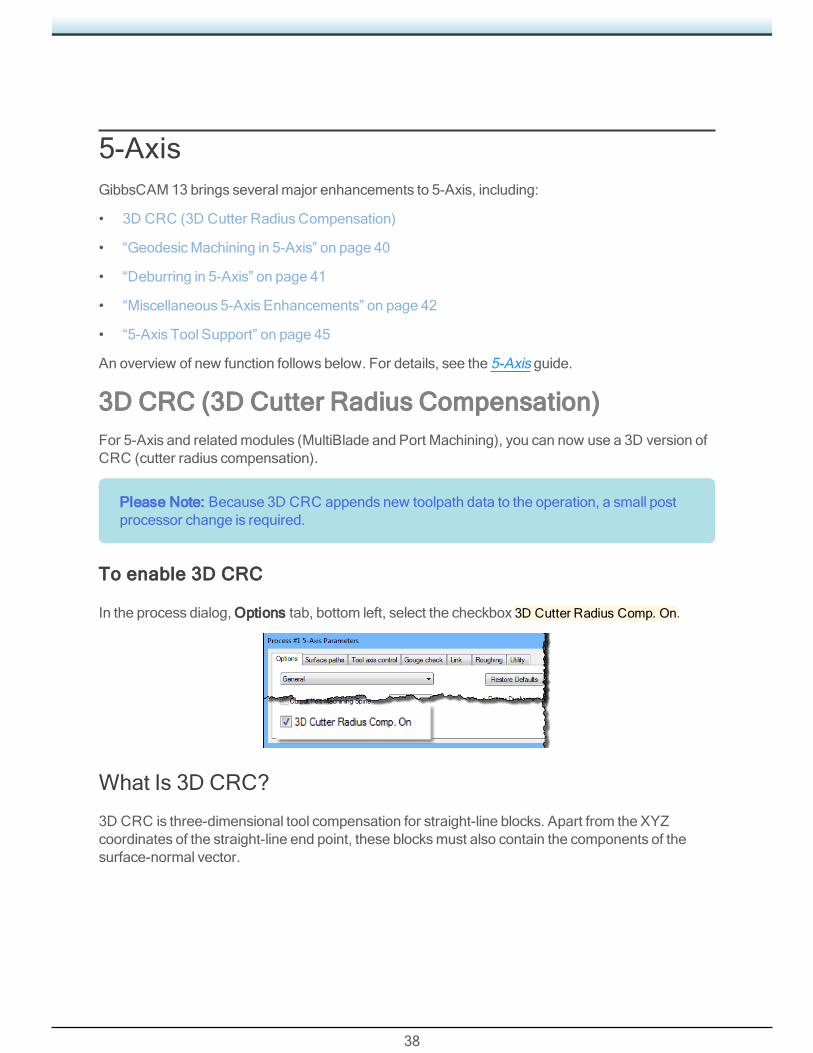
To enable 3D CRC
In the process dialog, Options tab, bottom left, select the checkbox 3D Cutter Radius Comp. On.
What Is 3D CRC?
3D CRC is three-dimensional tool compensation for straight-line blocks. Apart from the XYZcoordinates of the straight-line end point, these blocksmust also contain the components of thesurface-normal vector.
39
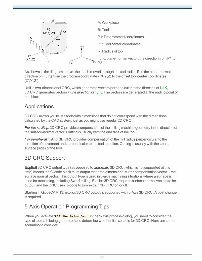
A: Workpiece
B: Tool
P1: Programmed coordinates
P2: Tool center coordinates
R: Radius of tool
I,J,K: plane-normal vector: the direction fromP1 toP2
As shown in the diagram above, the tool ismoved through the tool radius R in the plane-normaldirection of (I,J,K) from the program coordinates (X,Y,Z) to the offset tool center coordinates(X',Y',Z').
Unlike two-dimensional CRC, which generates vectors perpendicular to the direction of I,J,K,3D CRC generates vectors in the direction of I,J,K. The vectors are generated at the ending point ofthat block.
Applications
3D CRC allows you to use tools with dimensions that do not correspond with the dimensionscalculated by the CAD system, just as youmight use regular 2D CRC.
For facemilling: 3D CRC provides compensation of themillingmachine geometry in the direction ofthe surface-normal vector. Cutting is usually with the end face of the tool.
For peripheral milling: 3D CRC provides compensation of themill radius perpendicular to thedirection of movement and perpendicular to the tool direction. Cutting is usually with the lateralsurface (side) of the tool.
3D CRC Support
Explicit 3D CRC output type (as opposed to automatic 3D CRC, which is not supported at thistime) means theG-code blockmust output the three dimensional cutter compensation vector — thesurface normal vector. This output type is used in 5-axismachining situationswhere a surface isused for machining, including Swarf milling. Explicit 3D CRC requires surface normal vectors to beoutput, and the CNC usesG-code to turn explicit 3D CRC on or off.
Starting in GibbsCAM 13, explicit 3D CRC output is supported with 5-Axis 3D CRC. A post changeis required.
5-Axis Operation Programming Tips
When you activate 3D Cutter Radius Comp. in the 5-axis process dialog, you need to consider thetype of toolpath being generated and determine whether it is suitable for 3D CRC. Here are somescenarios to consider:
40
• Make sure the toolpath has sufficient lead-in and lead-out moveswhen CRC is turned on andoff; otherwise, it will gouge.
• If themachining surface has a sufficiently acute concave corner, then the tool will gouge theopposite surface while machining the current surface.
Geodesic Machining in 5-Axis
New Calculation Type: Geodesic Machining
Background
For non-prismatic features of a work piece, a common process of surface finishing is cutting withseveral parallel cuts to produce the final work piece geometry. Originally, it was quite common toproject parallel lines onto the free-form surface topology or slice with planes in a fixed direction tocreate "waterline" patterns. These patterns have the strengths of robustness and a relatively simplealgorithm. The weakness is that the distance between the cuts is not constant, but depends insteadon the surface topology/curvature and the local changes between two slices.
Geodesic
TheGeodesicMachining calculation for toolpath goes farther, generalizing the concept of a"straight line" mapped onto "curved spaces". Geodesic patterns take into account distances on thesurface topology.
Using a global distance field provides full flexibility to calculate various pattern typeswhilemaintaining consistent distances between cuts.
Features of Geodesic
• For offset or morph pattern types, single or multiple guide curves can be used as input. Even inan undercut situation (relative to a fixed direction) the algorithm outputs the same consistency ofsliceswhen generating the pattern.
• Tool centermode allows collision-free pattern generation even in sharp inner corners or stronglycurved areaswith multiple surface patches.
• Themorph pattern providesmore flexibility in terms of supported geometry. As the distance iscalculated on the surface topology, amuch higher precision of morph distance can be achievedeven if the guide curves are located close to each other.
• Boundary detection is provided for guide and containment curves.
• Extensions and hole-filling are available to avoid edge rolling and easy pattern extrapolation.Guide curve extension allows short curves to be extended to the surface boundary.
41
Deburring in 5-Axis
New Calculation Type: Deburring
After machining, burrs can be found on all parts that have straight edges or non tangent outersurface topologies, appearing whenever the tool chipsmetal off that edge. This can not only destroythe functionality of the part, it can endanger the worker. In almost all machining it is necessary todeburr the part after it ismachined.
Manual deburring can take asmuch time as the entire automated processing of a part. TheDeburring calculation strategry can greatly speed throughput by automating this last portion of thecycle, creating a deburring toolpath on the outer edges of part geometry. The position of the toolrelative to the edge is always the bi vector between the two surfaces of that edge.
The system provides automatic feature detection, automatic linking, automatic lead in, andautomatic collision avoidance. The goal is to create toolpath in a completely automated fashion justby selecting the part geometry.
Please Note: Only ball mill cutters are supported, and the geometry input (amesh) must bein a good quality for feature detection to work properly.
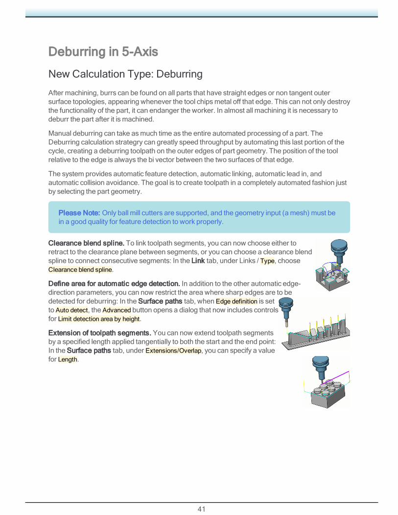
Clearance blend spline. To link toolpath segments, you can now choose either toretract to the clearance plane between segments, or you can choose a clearance blendspline to connect consecutive segments: In the Link tab, under Links / Type, chooseClearance blend spline.
Define area for automatic edge detection. In addition to the other automatic edge-direction parameters, you can now restrict the area where sharp edges are to bedetected for deburring: In the Surface paths tab, when Edge definition is setto Auto detect, the Advanced button opens a dialog that now includes controlsfor Limit detection area by height.
Extension of toolpath segments. You can now extend toolpath segmentsby a specified length applied tangentially to both the start and the end point:In the Surface paths tab, under Extensions/Overlap, you can specify a valuefor Length.

42
Relief Cuts. You can now specify that thetool is to be retracted out andsimultaneously shifted toward the innercorners in such a way that deburringalong a particular edge ismaximizedwithout compromising the work piece: Inthe Surface paths tab, under Pathparameters, when Inner corners is set toRelief, the Advanced button opens a dialogthat allows you to specify relief cuts withloop radius that you supply.
Miscellaneous 5-Axis Enhancements
General and Surface Path
Automatic start height when lead-in/out type is Position line. In the Link tab, inthe Entry/Exit section, when you chooseUse Lead-in or Use Lead-Out anduncheckUse default, the dialog box now offers a new option: Automatic startheight.
Rapid distance in tool plane. You can apply rapid distance (or feed distance)in the tool plane instead of the tool axis plane. This can be particularly helpful with undercut toolssuch as slot mills, where engagement is from the side and axial retractions are undesirable. In theLink tab, the Retracts dialog box'sDistances section now offers a new option: Rapid distance in toolplane.
Gradual front shift change. You can shift the tool contact point as it moves along the contour. Thiscan be used for polishing. In the Tool axis control tab, withRun tool set to At user given point, newcontrols are offered for Front shift, To, and Side shift.
Gradual side tilt angle for fixed angle to axis. In the Tool axis control tab when the tool axis tiltstrategy is Tilted with fixed angle to axis, ...
Linking: Clearance blend spline. For Large gaps and Largemoves, you can specify a clearancebland spline to link to contours.
Automatic arc as lead-in / lead-out.
Contact point based feedrate optimization. In the Utility tab, whenCalculation based on is set toSurfaces, a new checkbox in the Feedrate area allows you to ...
Surfaces: Tool axis smoothing. ...
Surfaces: Multiple surfaces for flowline. ...
Surfaces: Lead in using reverse orthogonal line. ...
43
Triangle Mesh andWireframe
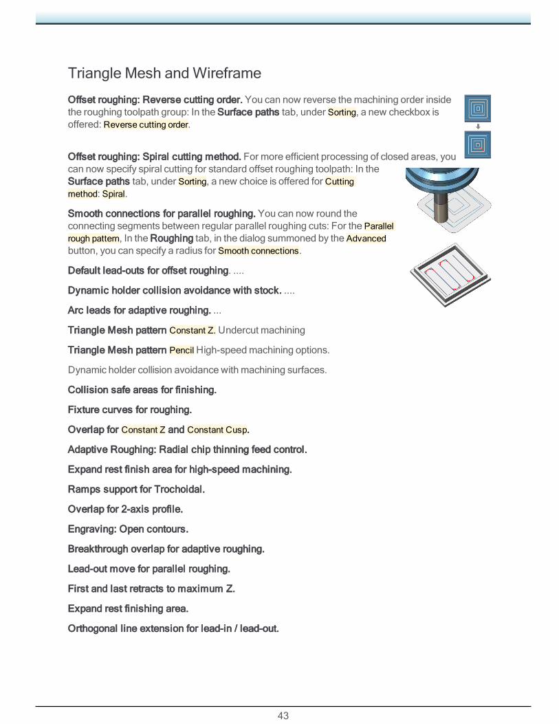
Offset roughing: Reverse cutting order. You can now reverse themachining order insidethe roughing toolpath group: In the Surface paths tab, under Sorting, a new checkbox isoffered: Reverse cutting order.
Offset roughing: Spiral cutting method. For more efficient processing of closed areas, youcan now specify spiral cutting for standard offset roughing toolpath: In theSurface paths tab, under Sorting, a new choice is offered for Cuttingmethod: Spiral.
Smooth connections for parallel roughing. You can now round theconnecting segments between regular parallel roughing cuts: For the Parallelrough pattern, In the Roughing tab, in the dialog summoned by the Advancedbutton, you can specify a radius for Smooth connections.
Default lead-outs for offset roughing. ....
Dynamic holder collision avoidance with stock. ....
Arc leads for adaptive roughing. ...
Triangle Mesh pattern Constant Z. Undercut machining
Triangle Mesh pattern PencilHigh-speedmachining options.
Dynamic holder collision avoidance with machining surfaces.
Collision safe areas for finishing.
Fixture curves for roughing.
Overlap for Constant Z and Constant Cusp.
Adaptive Roughing: Radial chip thinning feed control.
Expand rest finish area for high-speed machining.
Ramps support for Trochoidal.
Overlap for 2-axis profile.
Engraving: Open contours.
Breakthrough overlap for adaptive roughing.
Lead-out move for parallel roughing.
First and last retracts to maximum Z.
Expand rest finishing area.
Orthogonal line extension for lead-in / lead-out.
44
Maximum feedrate for adaptive roughing.
Smoother function improvements for roughing and Constant Z.
Start points for Engrave and Chamfering.
Lead-in / Lead-out for Engrave.
Start position improvements for Engrave.
Swarf Machining
Swarf: 4-axis tilting. Swarf machining can now be defined as a 4-axis solution: In the Tool axiscontrol tab, for Output format, choose 4-axis. The tool orientation is aligned for a complete 4-axiscycle.
Swarf: Cut from bottom. For some kinds of swarf machining, when you sortpattern slices using depth By slice distance, you can specify that passes occurfrom the bottom upwards: In theMulti Cuts, tab, whenDirection is set to Followsurface topology, checkCut from bottom.
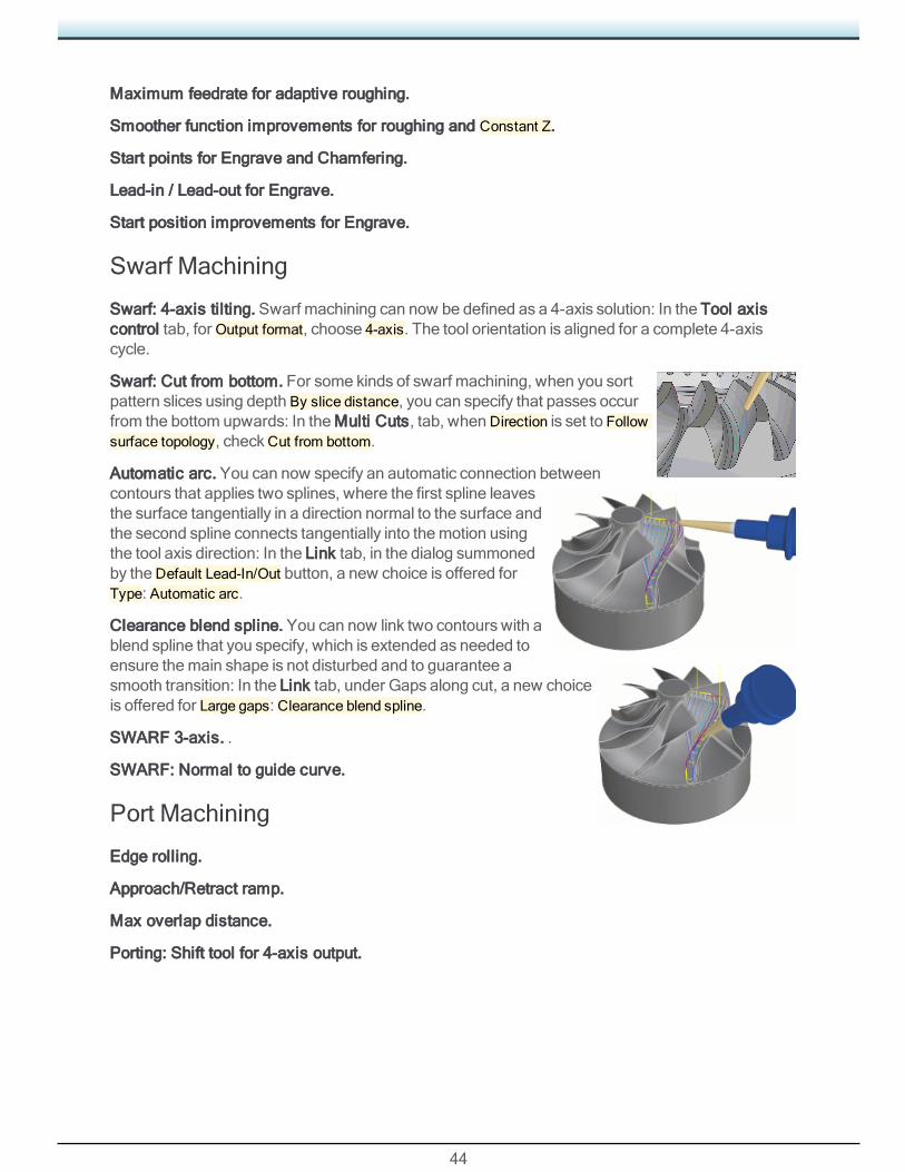
Automatic arc. You can now specify an automatic connection betweencontours that applies two splines, where the first spline leavesthe surface tangentially in a direction normal to the surface andthe second spline connects tangentially into themotion usingthe tool axis direction: In the Link tab, in the dialog summonedby theDefault Lead-In/Out button, a new choice is offered forType: Automatic arc.
Clearance blend spline. You can now link two contours with ablend spline that you specify, which is extended as needed toensure themain shape is not disturbed and to guarantee asmooth transition: In the Link tab, under Gaps along cut, a new choiceis offered for Large gaps: Clearance blend spline.
SWARF 3-axis. .
SWARF: Normal to guide curve.
Port Machining
Edge rolling.
Approach/Retract ramp.
Max overlap distance.
Porting: Shift tool for 4-axis output.
45
5-Axis Tool Support
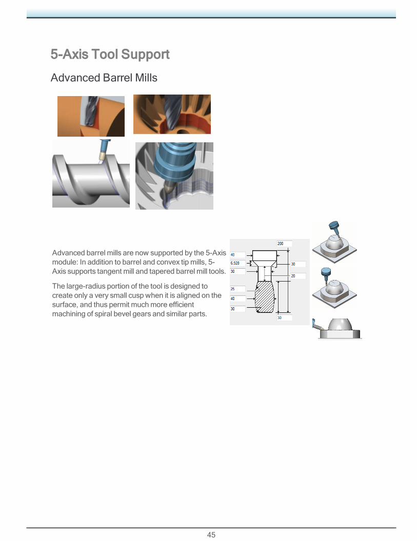
Advanced Barrel Mills
Advanced barrel mills are now supported by the 5-Axismodule: In addition to barrel and convex tip mills, 5-Axis supports tangent mill and tapered barrel mill tools.
The large-radius portion of the tool is designed tocreate only a very small cusp when it is aligned on thesurface, and thus permit muchmore efficientmachining of spiral bevel gears and similar parts.
Worth Another Look
46
Worth Another LookReleases prior to GibbsCAM 13 included several important enhancements that are oftenoverlooked:
• “Clearance Volume” on page 46
• “Did You Know Intermediate Tooling CanDo This, Too?” on page 48
• “Simple and Powerful Form Tool Definition” on page 47
An overview of this functionality follows below. For details, see the tbd, tbd, and tbd guides.
Clearance VolumeClearance Volume allows users of advancedmachines to say to GibbsCAM, in effect, “Here’smypart; don’t let the tool come too close to it except when cutting. You figure it out so I don’t have to.”
Clearance Volumewas devised to address situationswhere the traditional clearance plane (CP1)is not a goodmatch for machines of more than three axes, especially those with rotary heads ortables, tools with right-angle heads (or any tool that is not Z-aligned), vices that can be held atvarying B-axis angles, and the like.
For turning, Clearance Volume is required for eccentric turning, where clearancesmust becalculated from aCS that is not parallel to the base XZ axis.
The clearest example of where Clearance Volume is beneficial isWillemin 508MT and 508MT2machineswhere vice and tool can be rotated independently, making it impossible to provide legacyMDD settings for interopmoves that are logical and reasonable. Anymachine where tool stationsand part stations are independently rotatable can be a candidate for Clearance Volume.
Clearance Volume can also be useful for simplemachineswheremore efficient clearances aredesirable for interopmoveswhen the tool retracts to accommodate rotation, especially whenmachining a tall part. This occurs on 5-axis tablemachineswhere the fourth axis is distant from thepart, and on B-axismill-turns where the tool goes home between B-axis orientation changes. Incases like these, if you can keep the tool near the part, you often get faster run times.
Generally: If it is very difficult to calculate the “right” CP1, or if there is no right CP1, then ClearanceVolumemay offer a better solution.
Caveats: Interopmoves generated byClearance Volume contain 5-axis simultaneousmoves; thusit is best if the control has TCP capabilities, and it is unsuitable for machines that have indexingrotary axes or rotary axes that must be clamped betweenmoves.
User Interface
In theMDD, Clearance Volume should be implemented byResellers and/or the Gibbs PostDepartment. We do not expect end users to exercise Clearance Volume options in theMDD.

Worth Another Look
47
When theMDD implements Clearance Volume, a new command is available: ShowClearance Volumes. You can find this command in the Customization dialog and customize theuser interface by placing it on a toolbar or menu group.
DCD.When anMDDspecifies ClearanceVolume, the DCD for aMillpart changes: instead ofClearance for a planepositioned above the partorigin, it hasClearance (Δ) asan incremental offset fromthe default stock definition.
Machine Space and Part Space
Machine spacemeans “absolute; from the standpoint of themachine”; part space is relative to thepart, whichmay bemoving with respect to themachine.
Example. When a vinyl record is played on a turntable, consider the path of the needle.
• From the standpoint of themachine, it makes a nearly straight-line traversal from the outside ofthe disc to the inside.
• From the standpoint of the record, the needle traverses a very tight inward spiral, withoccasional small breaks. This follows the spiral tracks in the vinyl.
G-Code
All machines output G-code inmachine space; somemachines also have amode that enables partspace instead of machine space. Machine Space requires accurate offsets (i.e., tool and part androtary positions in theMDD), andmay be unsafe when inaccurate offsets are entered. Part Spaceismore forgiving. But: Note that “Turning Enabled” causes Part Space to be ignored.
In most circumstances, the superior output takes advantage of themachine’s interpolationcapabilities to create smooth lines and arcs, instead of creatingmany tiny segments thatapproximate a curve.
Simple and Powerful Form Tool DefinitionYoumight not realize that mixed geometry — a combination of blue (Wall) geometry and red (Air)geometry — is useful for more than just cleanup of open pockets.
When defining a 2D Form tool, you can incorporate bothWall and Air into the tool definition. UseWall geometry to represent the cutting portion of the tool and Air geometry to represent the non-cutting portion.

Worth Another Look
48
Did You Know Intermediate Tooling Can Do This,Too?You can use Intermediate Tooling to implement all the following:
• Y-axis Part Off/ Cut Off.
• Half tool indexing on turrets. (For example, the Haas BMT65 has half indexed tool locations, soinstead of 12 it can have 24 possible tools at one time.)
• Toolblocks that can holdmultiple tools in one turret position.