gl mod i l7 - nptelnptel.ac.in/courses/105108075/module2/lecture07.pdf · criteria stipulated a...
TRANSCRIPT

GROUND IMPROVEMENT
NPTEL Course
Prof. G L Sivakumar BabuDepartment of Civil EngineeringIndian Institute of ScienceBangalore 560012Email: [email protected]
Lecture 7
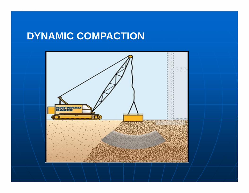
DYNAMIC COMPACTION
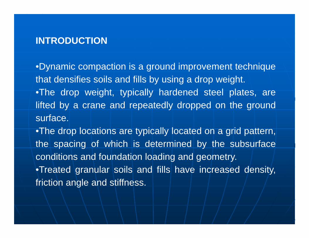
INTRODUCTION
•Dynamic compaction is a ground improvement techniquethat densifies soils and fills by using a drop weight.•The drop weight, typically hardened steel plates, arelifted by a crane and repeatedly dropped on the groundsurface.•The drop locations are typically located on a grid pattern,the spacing of which is determined by the subsurfaceconditions and foundation loading and geometry.•Treated granular soils and fills have increased density,friction angle and stiffness.

•The technique has been used to increase bearing capacity, and decrease settlement and liquefaction potential for planned structures.
•In shallow karst geologies, it has been used to collapse voids prior to construction, thereby reducing sinkhole potential.
•Dynamic compaction has also been used to compact landfills prior to construction of a parking lots, roadways, and to stabilise large area of embankment works.

•One of the most important considerations regarding theapplicability of dynamic compaction is the type of soilbeing densified.•In general, dynamic compaction is most beneficial on acategory of soil known as granular materials.•Granular materials enable excess pore water pressuresthat develop during the densification process to dissipaterapidly.•Dynamic compaction will be effective in silts, clayey siltsand sandy silts.

Approach for design
Poran and Rodriguez (1992) suggested an approach for design of dynamic compaction scheme in a project based on the approximate shape of the area compacted which is assumed as follows.
Approximate grid spacing

Plot of a/D and b/D vs. NWHh/Ab

1.The required significant depth of densification, DI is obtained from
DI = ½√(WHh)
Where DI = significant depth of densification (m)
WH= Weight of hammer (metric ton)
h = height of drop (m)
2.From the figure given above, DI = b
3.The hammer weight (WH), height of drop (h), dimensions of the cross section, and thus the area A and depth D is determined

4.Determine DI/D = DI/b
5.Using the plot given by Poran and Rodriguez (1992), determine the magnitude of NWHh/Ab for the value of b/D obtained.
6.Since the magnitude of WH, h, A and b are known (or assumed), the number of hammer drops can be estimated .
7.With known value of NWHh/Ab, determine a/D and thus a.
8.The grid spacing, Sg, for dynamic compaction may now be assumed to be equal to or somewhat less than a.

The following is a typical example,
Weight of the hammer, WH = 185kN
Height of drop, h =26m
Width of hammer, D = 5m
1.DI = ½√(WHh)
=½√(18.5*26) =10.96m
2.DI = b = 10.96 m, assume D= 5m A= 25 sq.m
3.DI/D=b/D= 10.96/5 = 2.2
4.From the plot given in fig 3 we got NWHh/Ab = 220 kN/m2
5.Since we know WH, h, A and b. Number of hammer drops, N= 14 blows

6.With the known value of NWHh/Ab, determine a/D from the fig 3 and thus a = 16 m .
7.The grid spacing, Sg ~ a = 16m.
Thus using a square plate of 5m for a height of drop of 26m (14 number of blows) at grid spacing of 16m, using a weight of 18.5 t tamping will enable 10.96 m depth of improvement.

The effectiveness of deep compaction is noted from analysis of construction process, pore pressure and settlement records, requirement of imported fill to achieve a certain grade, energy consumed by the equipment etc.
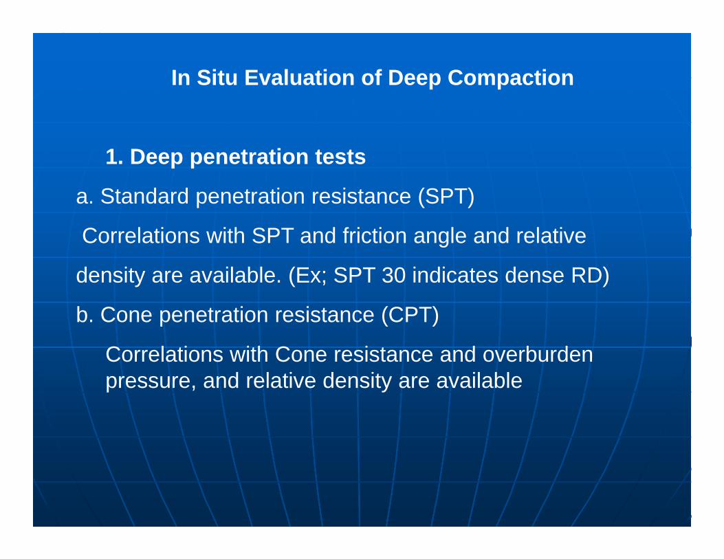
In Situ Evaluation of Deep Compaction
In Situ Evaluation of Deep Compaction
1. Deep penetration tests
a. Standard penetration resistance (SPT)
Correlations with SPT and friction angle and relative
density are available. (Ex; SPT 30 indicates dense RD)
b. Cone penetration resistance (CPT)
Correlations with Cone resistance and overburden pressure, and relative density are available

2.Compressibility estimates from penetration tests
a. Soil modulus and SPT results (E = 2.8 N MPa)
b. Stress- Strain parameters from cone penetration resistance (Constrained modulus E = 2.5 qc)
3. Stress-Strain modulus from pressuremeter tests
a.Menard Pressuremeter
b. Self Boring Pressuremeter
4. Dilatometer tests
5. Shear wave velocity measurements

Degree of ground improvement achieved by dynamic compaction

Self boring pressuremeter and kit

Shear –Wave Velocity tests Flat Dilatometer tests
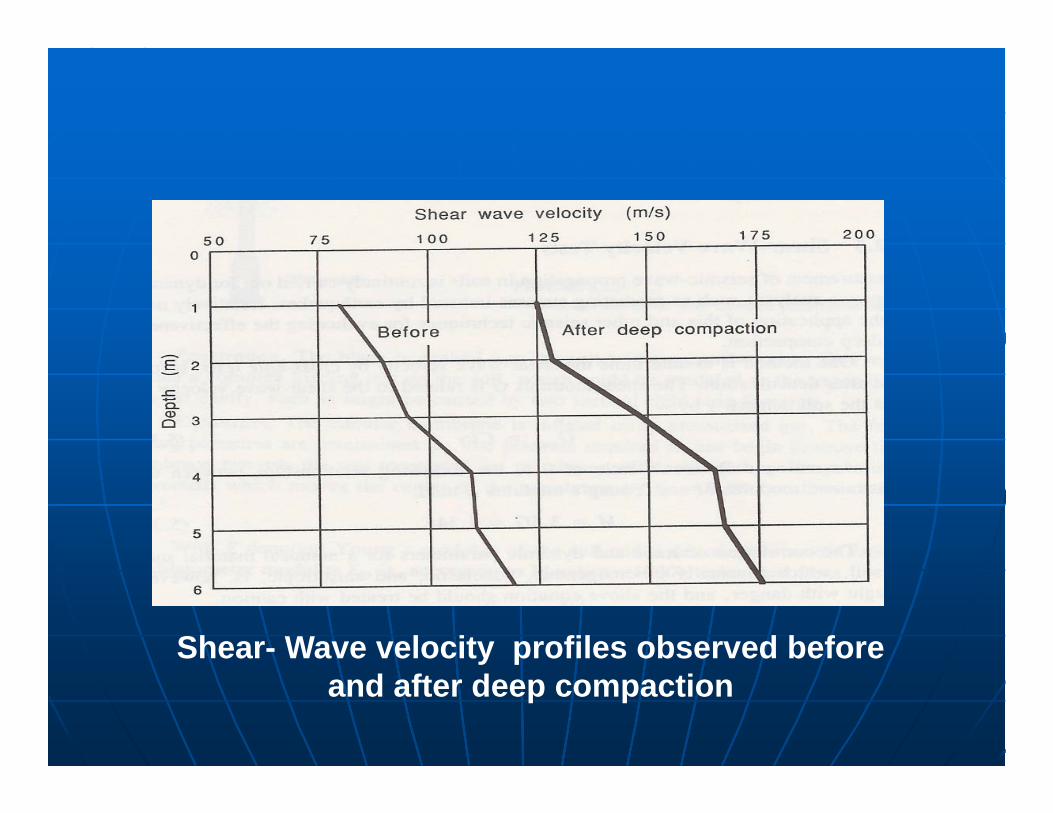
Shear- Wave velocity profiles observed before and after deep compaction

CASE STUDIES
Nice airport new runway - France
•An extension was made for the existing Nice airport byconstructing two new runways 3200 meters long, parallelto the shore line on a reclaimed land.•The soil conditions prevailing were loose fill, some stiffmarls and deposits of soft sandy silts.•Hence there was a need for heavy dynamic compaction inand around the runway.

•The project involved the placement of about 20,000,000m³ of fill to build a reclaimed platform of 200 ha. Theborrow pit was situated at 13 km from the main site. Thetransport was made by means of a fleet of 38 dumpertrucks with trailer 145 tons total weight.•The evolution of pore water pressure was continuouslymonitored at various depth during DC. Works have beendone in successive phases with sufficient resting periodsto avoid building excess pore pressure. The volumeversus DC energy governed the intensity of thetreatment. During Dynamic Compaction and aftertreatment numerous CPT, PMT, have been performed tocontrol fill characteristics.

Shuaiba IWPP III - Desalination Plant -Saudi Arabia
•Shuaiba Independent Water & Power Project (IWPP)was planned to meet the growing demands of water andelectricity in Saudi Arabia’s Shuaiba region, 110 km fromJeddah.•Site had two types of soil profiles. In the first profilethere was loose to dense silty sand and second profilewas composed of soft silt or very loose silty sand. Thislayer was followed by the bedrock.

•The project consisted of 12 evaporators, 3 water tanks anda number of related buildings. The tank’s diameter andheight were respectively 106.6 m and 20 m. The designcriteria stipulated a bearing capacity and maximumsettlement of respectively 200 kPa and 75 mm for thetanks. For the other structures, the same were required tobe 150 kPa and 25 mm respectively.•Due to the presence of loose sands and soft silts, it wasdecided to optimize the foundation solution byimplementing dynamic compaction and dynamicreplacement in the project. The choice of this techniquewas dependant on the soil characteristics.

•Upon completion of soil improvement works, 75 pressuremeter tests (PMT) and one zone load test were used todemonstrate that the acceptance criteria had beenachieved. The results of the tests clearly indicated thatsuccess of the ground improvement project, and theability of the foundations to safely support the designloads.
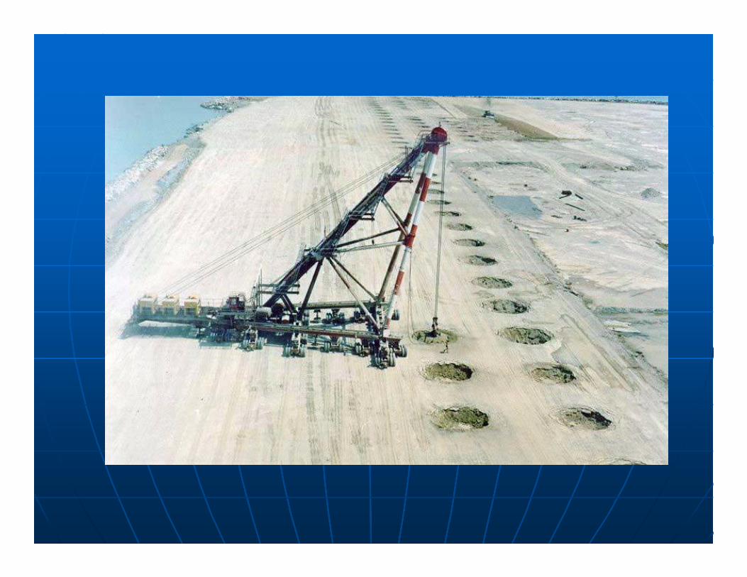
Abu Dhabi New Corniche Road-UAE
•New Corniche road was widened up to 200m byreclamation of 900000 m2 using dredged sand for a depthvarying from 4m to 12m.•This structure, of length 4750m, anchored with sheetpiles, could not be embedded into hard bedrock, and it wasnecessary to be equilibrated by a well compactedsubmarine backfill to generate necessary horizontalreaction.• Dynamic Compaction ( with 15T pounder)and High Energy DC( with 25T pounder) was done for main part of fill with special emphasis on areas with silt pockets.
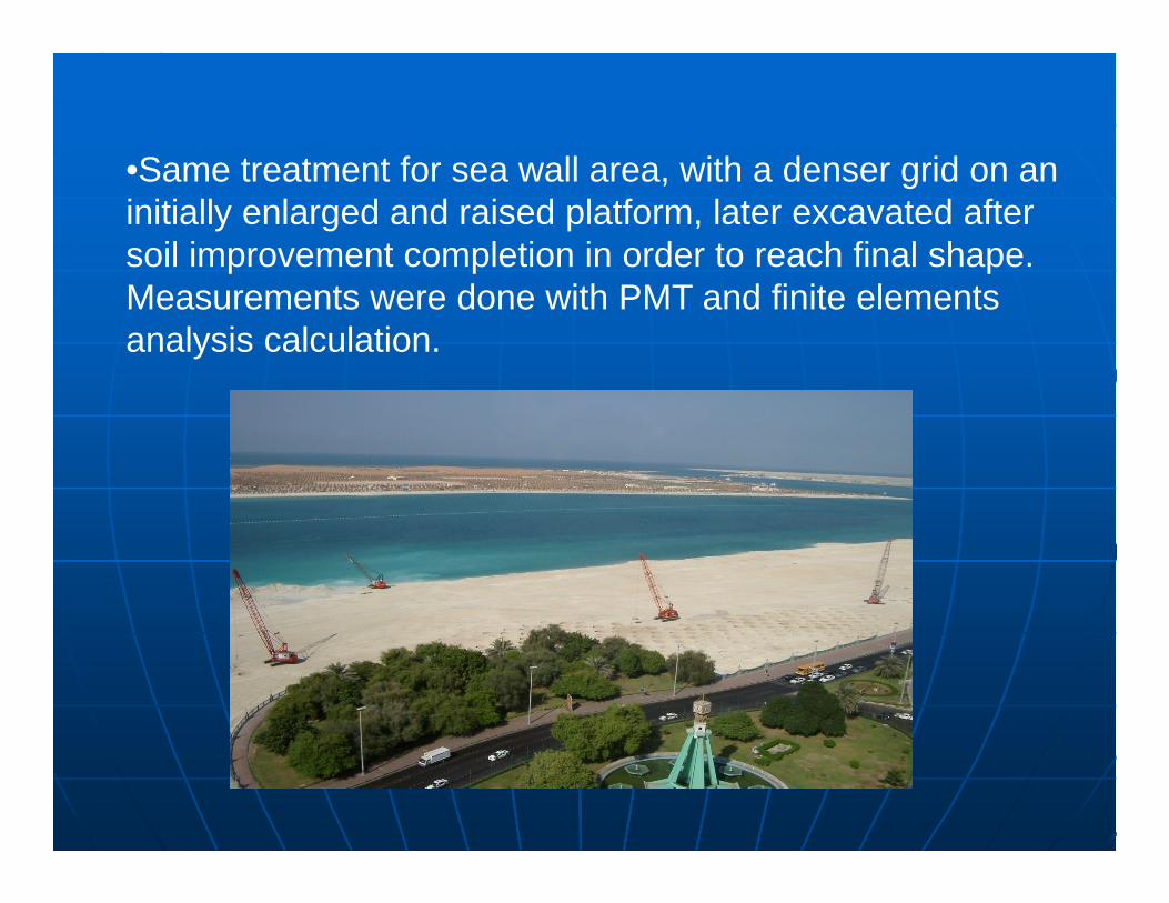
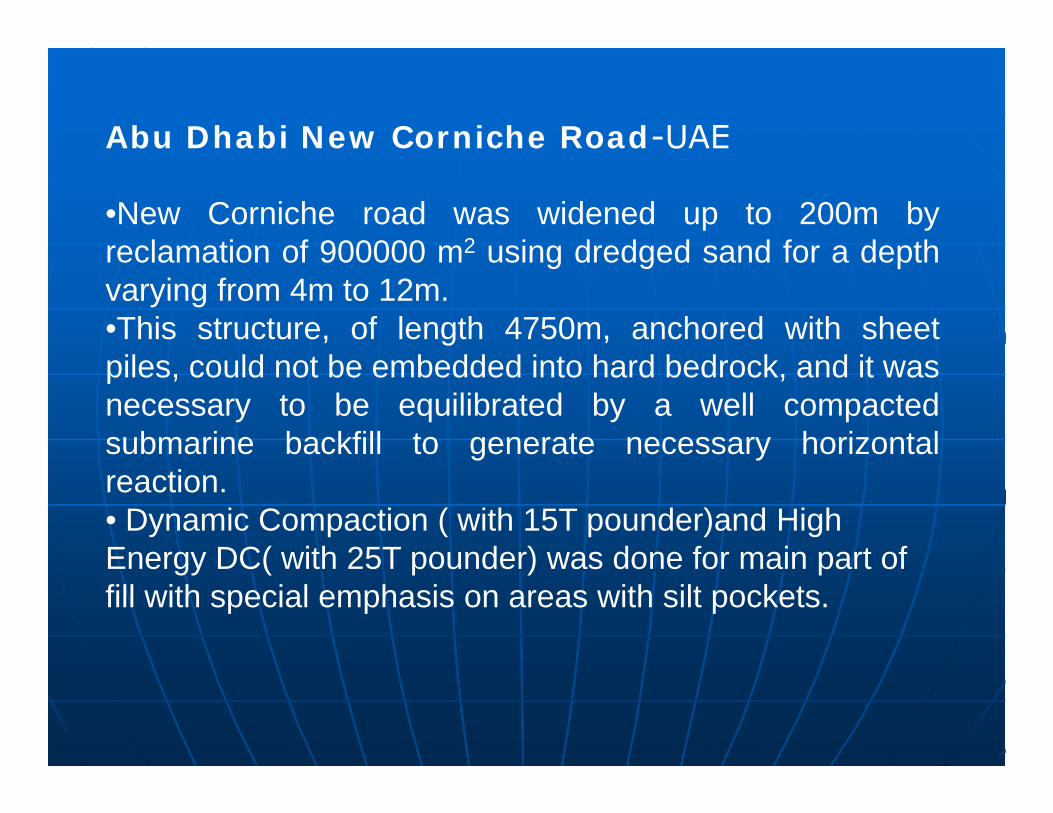
•Same treatment for sea wall area, with a denser grid on an initially enlarged and raised platform, later excavated after soil improvement completion in order to reach final shape. Measurements were done with PMT and finite elements analysis calculation.

Dynamic compaction for T.C.L. fertilizercomplex at Babrala, U.P.
The soil at Babrala consisted of a surface layer of loosesilty sandy clay of 1-2 meters depth underlain by loose finesand depths of 10-12 meters. This in turn is underlain by siltysandy clay.
Parameters available at site before the treatment indicatethat the allowable net bearing capacity was 60 kPa. Aseismic risk analysis of the site fixed the design earthquakeas one of magnitude 6.4 with a peak acceleration of 0.2gwhich could induce significant liquefaction.

The effectiveness of this technique at the site wasestablished by treating two areas, 30x30 meters each,by dynamic Compaction.

Measurement of improvement was done by SPT and SCPT testing. The results of the exercise are shown in fig. 2. The results also demonstrate the increase in strength with time.

Targeted response and treatment
Based on the results from trials, modifications were introduced to obtain an allowable bearing pressure of 200 kPa at 2m depth and that no liquefaction will occur in the improved ground during the design earthquake.
Treatment consisted of four passes. The first pass was with a 10 ton hammer falling 16m. The second pass was similar. But the locations are staggered. The third pass is with 15 t hammer falling 16m. The final pass was with a 5 ton hammer falling 16m on a grid of 2.5x2.5m.

Quality monitoring The treated soil was by the SPT ‘N’ values as assurance against liquefaction and allowable bearing pressure are specified in terms of SPT ‘N’ values obtained.
The area treated was divided into sub areas as shown earlier and the results of the program are shown in figures 3,4,5.

•Dynamic Compaction was successful insignificantly increasing the strength of the soil.This translates to a more than threefold increasein bearing capacity over that of the initial designrecommendation prior to treatment.
•The soils treated were loose sands to a depth of12.5 meters. Bearing capacities were increasedfrom 60 to 200 kPa and the site earthquakeproofed to the design earthquake.
Conclusions

•Ground Improvement using dynamic compaction is very cost effective and competitive with alternate foundation systems such as piling, excavation and backfilling and other similar techniques.
•Useful when large foundation areas need treatment and cost effective depending on the size of the project, type of soil conditions, depth of treatment required, cost of suitable fill material etc.

Acknowledgments
Engr. Sarfraz Ali, Prof. Gandhi IIT Madras.
http://www.haywardbaker.com/
/http://www.menard-web.com/
Haussmann M R (1990) Engineering principles of ground modification