gladiator hydra series owner’s manual · user manual gladiator hydra chillers page 2 ... also a...
TRANSCRIPT
User Manual Gladiator HYDRA Chillers Page 1
Revision 4
October 2019
Gladiator HYDRA Series
Owner’s Manual This guide applies to the following models: GA10(D)–HYD to GA35(D)–HYD
Aqua Cooler Pty Ltd
U14, 2-12 Knobel Court
Shailer Park 4128 Qld
www.aquacooler.com.au
1300 AQUA COOLER
1300 278 286

User Manual Gladiator HYDRA Chillers Page 2
Table of Contents
Introduction .......................................................................................................................................... 4
General Information .......................................................................................................................... 4
Denomination .................................................................................................................................... 4
Safety ................................................................................................................................................ 5
First Aid ............................................................................................................................................ 6
Installation Requirements .................................................................................................................... 6
Installation of the Water Path............................................................................................................ 7
Water Connection Fittings by Model (Male BSPT) ......................................................................... 8
Electrical Installation ........................................................................................................................ 8
Preparations For Starting the Chiller ................................................................................................... 8
Operating Sequence .......................................................................................................................... 9
Operating Precautions ....................................................................................................................... 9
Multiple Chiller Installations .......................................................................................................... 10
Pump Model by Chiller ...................................................................................................................... 10
Pump Curves ................................................................................................................................... 11
Redundant Pumps ........................................................................................................................... 13
Aqua Cooler Controller ...................................................................................................................... 13
Unlocking the Keypad on the Aqua Cooler Controller ................................................................... 13
Operational Logic of Controller ......................................................................................................... 13
Start Up ........................................................................................................................................... 13
Temperature Control-Set Point ....................................................................................................... 13
Temperature Control-Max and Min Set Point ................................................................................ 13
Temperature Control-High and Low Temperature Alarm Stop...................................................... 13
Fan Speed Control-Optional ........................................................................................................... 14
High/Low Pressure Control ............................................................................................................ 14
Water Flow/Pump Control .............................................................................................................. 14
User Manual Gladiator HYDRA Chillers Page 3
Compressor Hold Time ................................................................................................................... 15
Alarm Acknowledge Delay ............................................................................................................. 15
Pump Delay Time ........................................................................................................................... 15
Tandem Control .............................................................................................................................. 15
Close Tolerance............................................................................................................................... 16
Full Setting List .................................................................................................................................. 21
Advanced Controller Functions ......................................................................................................... 23
Downloading Data Log ...................................................................................................................... 23
Calibration of Sensors-Aqua Cooler Controller.............................................................................. 24
Updating Software .......................................................................................................................... 25
Controller Input and Output Schematic .......................................................................................... 26
Poor Heat Dissipation ..................................................................................................................... 29
Low Refrigerant .............................................................................................................................. 30
Low and High Pressure Difference ................................................................................................. 30
Compressor Not Starting ................................................................................................................. 30
Maintenance ....................................................................................................................................... 30
Recommended Preventative Maintenance Program ....................................................................... 31
Warranty............................................................................................................................................. 31
General Application ........................................................................................................................... 31
Installation Sketch Map of Air Cooled Chiller ............................................................................... 32
Installation Sketch Map of Water Cooled Chiller ........................................................................... 33
Internal Structure Sketch Map of Air Cooled Chiller ..................................................................... 34
Internal Structure Sketch Map of Water Cooled Chiller ................................................................. 35
Commissioning Sheet ........................................................................................................................ 36
Notes ................................................................................................................................................. 39
User Manual Gladiator HYDRA Chillers Page 4
INTRODUCTION
Thank you for choosing an Aqua Cooler chiller. In order to use this chiller correctly and efficiently,
please read the following instructions in detail. This manual is designed to explain the installation,
operation and the basic maintenance of the product. It is recommended that for service issues Aqua
Cooler Pty Ltd be contacted before any work commences.
General Information
The chiller is designed to refrigerate and circulate water to a heat developing process to aid in keeping
that process cool. They are supplied with an immersed coiled evaporator, or plate heat exchanger, or
shell&tube evaporator (model dependant), an air-cooled condenser and a scroll compressor to
circulate the refrigerant gas. Water is circulated out of the unit via a pump. The chiller is designed to
be installed outdoors and refrigerate water for a heat developing process – not for drinking or food
preparation purposes. Any other use of this water chiller is not as it is intended.
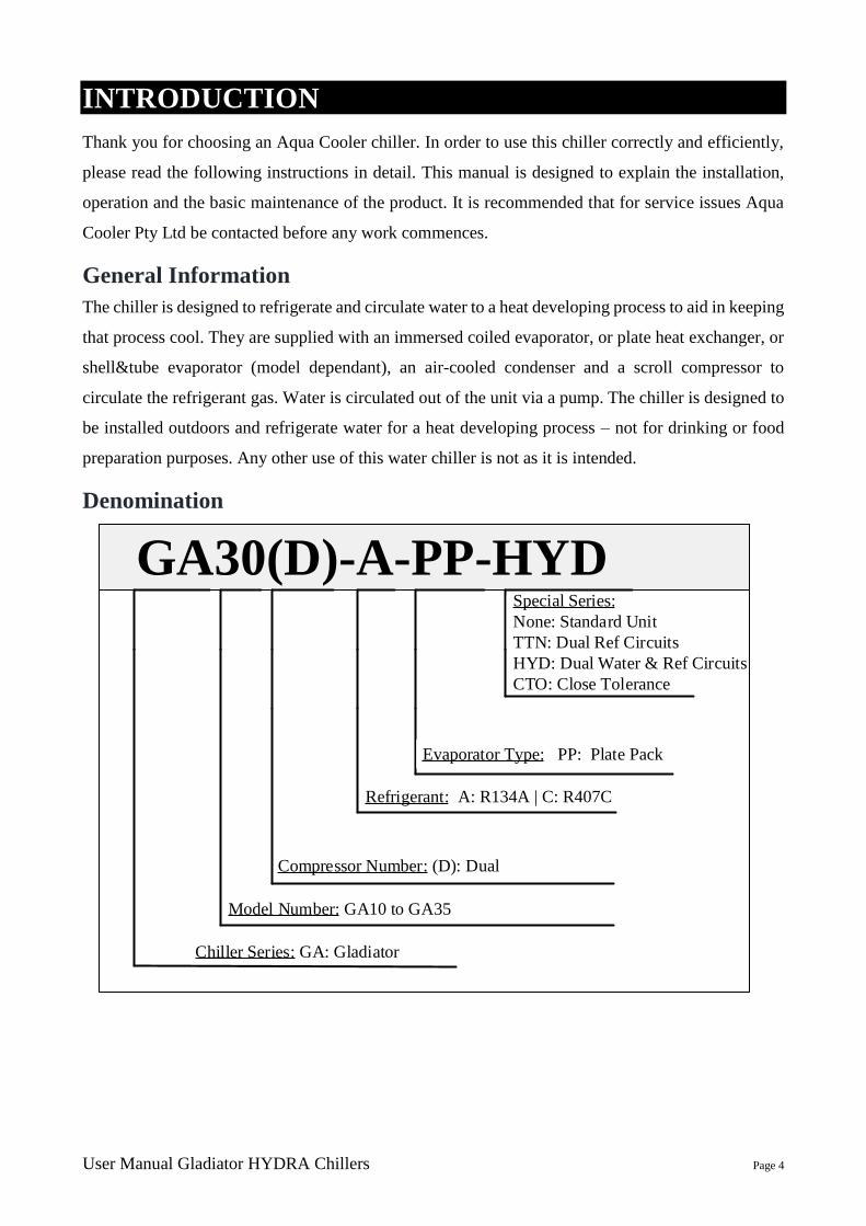
Denomination
Chiller Series: GA: Gladiator
Compressor Number: (D): Dual
GA30(D)-A-PP-HYDSpecial Series:
None: Standard Unit
TTN: Dual Ref Circuits
HYD: Dual Water & Ref Circuits
CTO: Close Tolerance
Evaporator Type: PP: Plate Pack
Refrigerant: A: R134A | C: R407C
Model Number: GA10 to GA35
User Manual Gladiator HYDRA Chillers Page 5
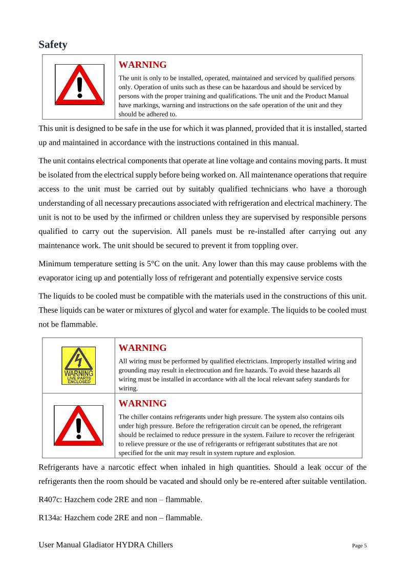
Safety
WARNING
The unit is only to be installed, operated, maintained and serviced by qualified persons
only. Operation of units such as these can be hazardous and should be serviced by
persons with the proper training and qualifications. The unit and the Product Manual
have markings, warning and instructions on the safe operation of the unit and they
should be adhered to.
This unit is designed to be safe in the use for which it was planned, provided that it is installed, started
up and maintained in accordance with the instructions contained in this manual.
The unit contains electrical components that operate at line voltage and contains moving parts. It must
be isolated from the electrical supply before being worked on. All maintenance operations that require
access to the unit must be carried out by suitably qualified technicians who have a thorough
understanding of all necessary precautions associated with refrigeration and electrical machinery. The
unit is not to be used by the infirmed or children unless they are supervised by responsible persons
qualified to carry out the supervision. All panels must be re-installed after carrying out any
maintenance work. The unit should be secured to prevent it from toppling over.
Minimum temperature setting is 5°C on the unit. Any lower than this may cause problems with the
evaporator icing up and potentially loss of refrigerant and potentially expensive service costs
The liquids to be cooled must be compatible with the materials used in the constructions of this unit.
These liquids can be water or mixtures of glycol and water for example. The liquids to be cooled must
not be flammable.
WARNING
All wiring must be performed by qualified electricians. Improperly installed wiring and
grounding may result in electrocution and fire hazards. To avoid these hazards all
wiring must be installed in accordance with all the local relevant safety standards for
wiring.
WARNING
The chiller contains refrigerants under high pressure. The system also contains oils
under high pressure. Before the refrigeration circuit can be opened, the refrigerant
should be reclaimed to reduce pressure in the system. Failure to recover the refrigerant
to relieve pressure or the use of refrigerants or refrigerant substitutes that are not
specified for the unit may result in system rupture and explosion.
Refrigerants have a narcotic effect when inhaled in high quantities. Should a leak occur of the
refrigerants then the room should be vacated and should only be re-entered after suitable ventilation.
R407c: Hazchem code 2RE and non – flammable.
R134a: Hazchem code 2RE and non – flammable.

User Manual Gladiator HYDRA Chillers Page 6
First Aid
Eye Contact: Immediately flush with tepid water or sterile saline solution. Hold eyelids apart for 15 minutes
while irrigating. Seek medical attention.
Inhalation: Remove from the area of exposure immediately and if you are assisting a victim to avoid being
exposed. Breathing apparatus must be worn in the presence of high concentration of refrigerants. If
victim is not breathing then apply artificial respiration and seek urgent medical help. Give oxygen
is available.
Skin Contact: Cold Burns. Remove contaminated clothing and gently flush affected area with warm water (30°C)
for 15 minutes. Apply sterile dressing and treat as for a thermal burn. For large burns immerse in
water for 15 minutes. DO NOT apply any form if direct heat. Seek medical attention.
Ingestion: For advice contact the poisons centre on 131126 in Australia. If swallowed do not induce vomiting.
Ingestion is considered unlikely due to product form. Advice to Doctor. Use of adrenaline and
other catecholamines may be contraindicated due to possible cardiac sensation. Treatment for
asphyxia.
INSTALLATION REQUIREMENTS
Immediately upon receipt of the chiller, carefully inspect the chiller for any damage that may have
occurred in transit. Any such damage must be noted on the carrier’s delivery documents. It is the
consignee’s responsibility to make any subsequent claims upon the carrier or respective insurance
company. Any hidden damage should be reported to Aqua Cooler as soon as possible.
If the unit is to be stored before installation, then care must be taken to ensure no foreign matter can
get into the water pipes. If the storage is for a prolonged period, it is recommended that the water
circuit be changed with nitrogen and sealed.
A comprehensive commissioning program carried out by qualified refrigeration mechanics is
available through Aqua Cooler. For full details and conditions please contact Aqua Cooler. There is
also a site inspection procedure at the end of this manual.
The unit has been designed to be lifted with a forklift or a crane. The care must be taken when lifting
with a crane that the strapping does not damage the side panels. The units are also designed to be
moved around with a pallet jack.
The commissioning section at the end of this manual has a site inspection checklist designed to aid in
checking that the site for the chiller installation is suitable. This should be filled out by someone
experienced in chiller installation and returned to Aqua Cooler if there are any doubts about the
installation. It is essential to ensure that adequate and safe service access to the chiller is provided.
Failure to provide safe access to the chiller may lead to additional charges should servicing be
required.
When installing indoors it is important to understand that the chiller will impart a significant heat
load into the environment, and it is essential to ensure a plentiful, unrestricted supply of ambient
User Manual Gladiator HYDRA Chillers Page 7
temperature air to the chiller. Should you have concerns over the installation site then please contact
Aqua Cooler for advice.
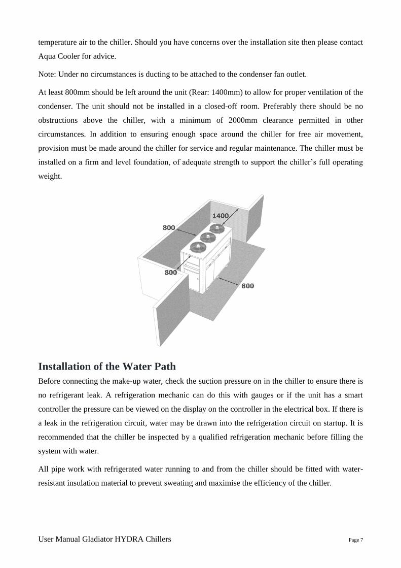
Note: Under no circumstances is ducting to be attached to the condenser fan outlet.
At least 800mm should be left around the unit (Rear: 1400mm) to allow for proper ventilation of the
condenser. The unit should not be installed in a closed-off room. Preferably there should be no
obstructions above the chiller, with a minimum of 2000mm clearance permitted in other
circumstances. In addition to ensuring enough space around the chiller for free air movement,
provision must be made around the chiller for service and regular maintenance. The chiller must be
installed on a firm and level foundation, of adequate strength to support the chiller’s full operating
weight.
Installation of the Water Path
Before connecting the make-up water, check the suction pressure on in the chiller to ensure there is
no refrigerant leak. A refrigeration mechanic can do this with gauges or if the unit has a smart
controller the pressure can be viewed on the display on the controller in the electrical box. If there is
a leak in the refrigeration circuit, water may be drawn into the refrigeration circuit on startup. It is
recommended that the chiller be inspected by a qualified refrigeration mechanic before filling the
system with water.
All pipe work with refrigerated water running to and from the chiller should be fitted with water-
resistant insulation material to prevent sweating and maximise the efficiency of the chiller.

User Manual Gladiator HYDRA Chillers Page 8
Water Connection Fittings by Model (Male BSPT)
Models: GA10(D)–HYD
GA15(D)–HYD
GA18(D)–HYD
GA20(D)–HYD
GA25(D)–HYD
GA30(D)–HYD
GA35(D)–HYD
Water Out: 1½” 2”
Water In: 1½” 2”
Drain: 1” 1”
Overflow: 1” 1”
Water Supply: ½” ½”
Electrical Installation
The chiller draws a large amount of current and it is important that the connection of the unit to the
power supply must be carried out in accordance with Australian standards and only by a licensed
electrician.
The power supply system on-site and the circuit protection must be designed for the total current of
the unit taking into account the inrush current and the lock rotor amps of the compressor– see the
brochure. The circuit breaker must be set no more than 125% of the units rated load current.
Mains supply cables must be sized to ensure adequate voltage at the chiller under all load conditions.
Three-phase power must be symmetrical, ensuring equal effective voltage and equal phase angle
between consecutive phases. The pump and the compressor rely on correct phase rotation. Ensure all
electrical connections are tight prior to starting up.
PREPARATIONS FOR STARTING THE CHILLER
For the initial operation of the chiller, please confirm the following:
1. The power supply voltage and phase should be in accordance with the specifications listed on
the chiller’s marking plate.
2. Check the pipe and return water pipe are connected properly and the valve is open.
3. Fill the water tank with water or coolant before starting the water pump. (Ensure you are using
a suitable coolant according to your requirements)
4. For water-cooled units, please pay attention to the moving direction of the water pump and
confirm the tower fans are not moving in the opposite direction. If the pump is three-phase,
change any two relative phase lines to reverse its direction. Then close the switch after
connections have been made.

User Manual Gladiator HYDRA Chillers Page 9
Before starting up the chiller have the following installation requirements been carried out
1. The power supply voltage and phase should be in accordance with the specifications listed on
the chiller’s marking place.
2. Check the ventilation of the unit.
3. Check the refrigerant leak through pressure gauge before filling the unit with water.
4. Check the bypass in the tank. Make sure it’s clossed to ensure the water flow to application.
5. Check the power supply according to the requirements.
Operating Sequence
1. Open the valve of the supply pipe and return pipe and ensure the waterway is unimpeded.
2. Turn the unit on with the master power switch.
3. Press the run button on the interface panel to start the controller.
4. Press the compressor start button on the interface panel to start the compressor.
5. Pressing the power button while the unit is running will power off the unit.
The unit is ready to be started up. Once power is provided to the chiller, open the clear plastic guard
over the ON/OFF switch and turn the unit on and the unit will start automatically. The pump will start
immediately. The compressors have a start delay. Once the compressors have cut in, watch the display
to ensure that the water temperature in coming down. Set points and operational parameters are
displayed on the screen. Any faults are indicated on the face of the control panel.
It is a good idea after the unit has been running for 5 minutes check that the water temperature is
dropping and check there are no bubbles in the sight glass (if fitted) – if these two things are happening
then the unit is running properly. Give the system a final check to ensure that there are no water and
refrigerant leaks.
Operating Precautions
1. Chilled water pump cannot be started without water in the water tank.
a. All standard models are equipped with water level protection in the water tank (except
for closed water tanks). The default setting is when the water level is too low, the unit
will throw an alarm and the pump will keep operate. However, this function can be
changed in controller. Once the function is changed, pump will stop running if water
level gets too low. Please make sure the function setting fits the application
requirement.
(Manufacturer Parameters – Control Setting – Low water lv. & Lack of water)
2. Switching the operating switches frequently should be avoided.
3. When the chilled-water temperature reaches the set temperature, the compressor will stop.
4. In order to prevent the evaporator freezing, do not set temperature below 5 °C. (Except for
sub-zero models)
5. When the unit is not in use for long periods of time, drain the tank.
6. To ensure the most efficient operation, please clean the condenser, evaporator, and the water
filter (if fitted) regularly.
User Manual Gladiator HYDRA Chillers Page 10
Multiple Chiller Installations
Aqua Coolers chiller can be installed in multiple installations for redundancy or to allow scaling as
process application increases in size – for example adding power to a data centre.
There are some requirements for the installation to prevent issues when the chillers duty cycle or if a
chiller develops a fault and the central controller or BMS starts another one.
The requirements are
1. The chillers must be ordered with the flood back option – this hydraulically isolated the chiller
when it is in standby mode. There is a motorized ball valve on the return water line and a
check valve on the water outlet line
2. A drain header must be installed between the chillers. This allows the water level in all the
chillers to same. Obviously this will not work if the chillers are installed at different levels.
3. The controller in the chiller has a high water temperature alarm acknowledge delay. This
setting needs to be set to at least 2 minutes. When the chills duty-cycle the water sitting in the
tank of the standby chiller can get warm especially on warmer days and when the chiller starts
up the high temperature alarm will activate – this alarm delay will give the chiller time to start
cooling the water and allow cold water in the pipe work to stir the tank. See the service and
maintenance section of the manual on how to change this setting.
Standard Aqua Cooler chiller can be installed together in pairs and one of the chillers will act as the
master and the other the slave and the master will duty cycle the chillers and keep a healthy. If there
are more than two chillers Aqua Cooler can supply a central chiller controller to monitor and duty
cycle the chillers
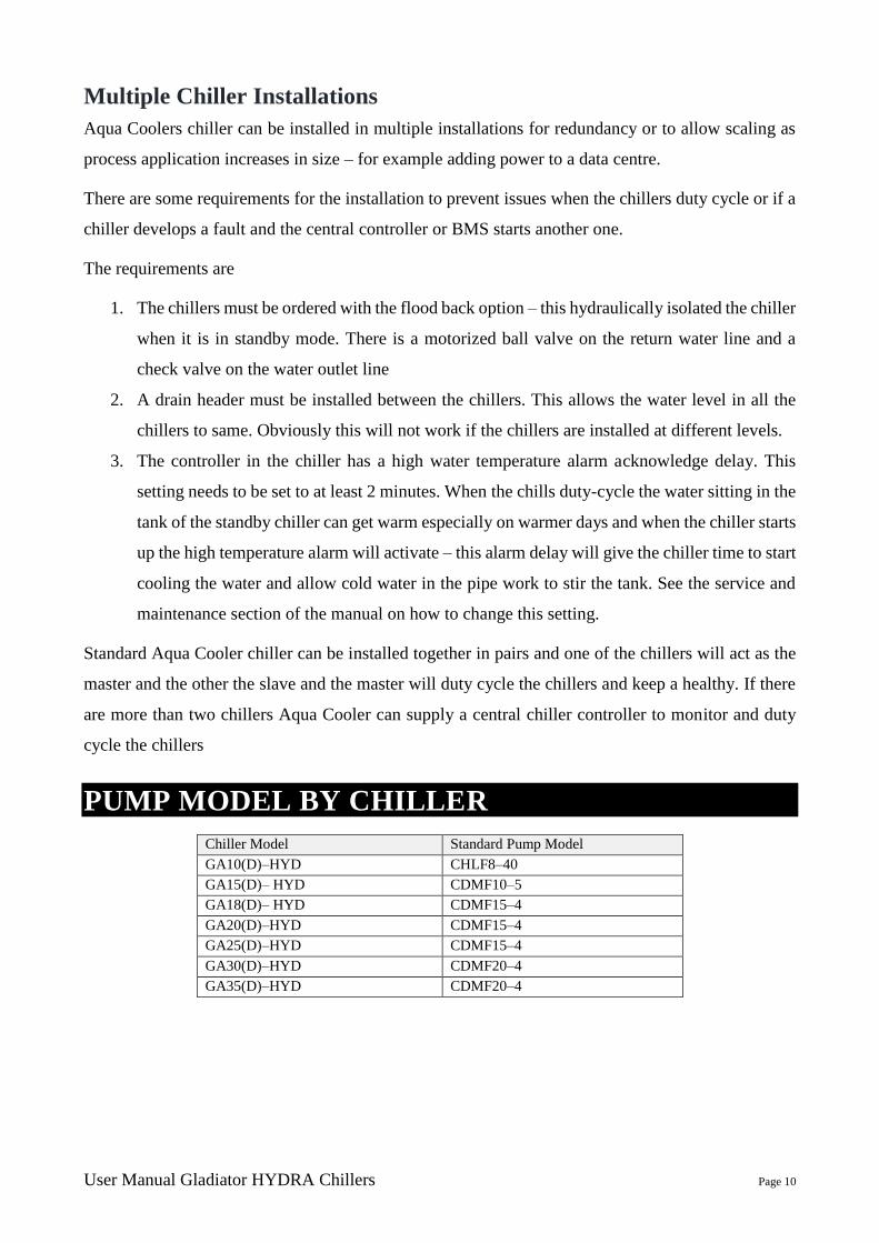
PUMP MODEL BY CHILLER
Chiller Model Standard Pump Model
GA10(D)–HYD CHLF8–40
GA15(D)– HYD CDMF10–5
GA18(D)– HYD CDMF15–4
GA20(D)–HYD CDMF15–4
GA25(D)–HYD CDMF15–4
GA30(D)–HYD CDMF20–4
GA35(D)–HYD CDMF20–4
User Manual Gladiator HYDRA Chillers Page 11
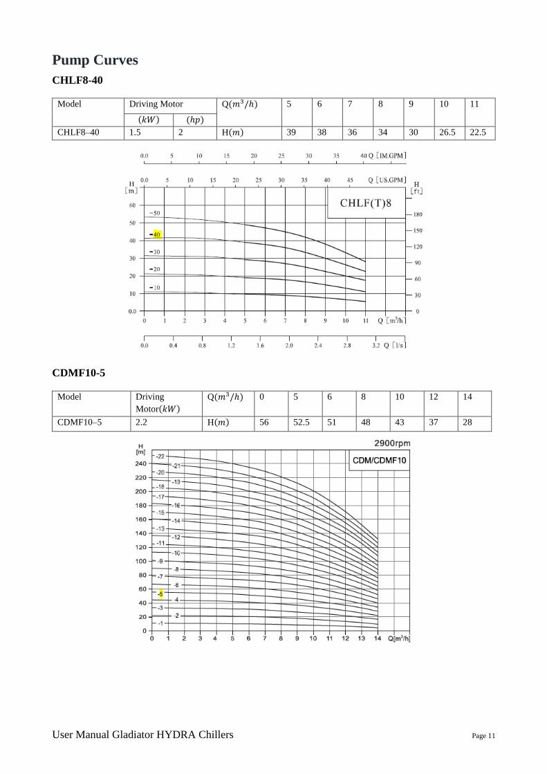
Pump Curves
CHLF8-40
Model Driving Motor Q(𝑚3/ℎ) 5 6 7 8 9 10 11
(𝑘𝑊) (ℎ𝑝)
CHLF8–40 1.5 2 H(𝑚) 39 38 36 34 30 26.5 22.5
CDMF10-5
Model Driving
Motor(𝑘𝑊)
Q(𝑚3/ℎ) 0 5 6 8 10 12 14
CDMF10–5 2.2 H(𝑚) 56 52.5 51 48 43 37 28
User Manual Gladiator HYDRA Chillers Page 12
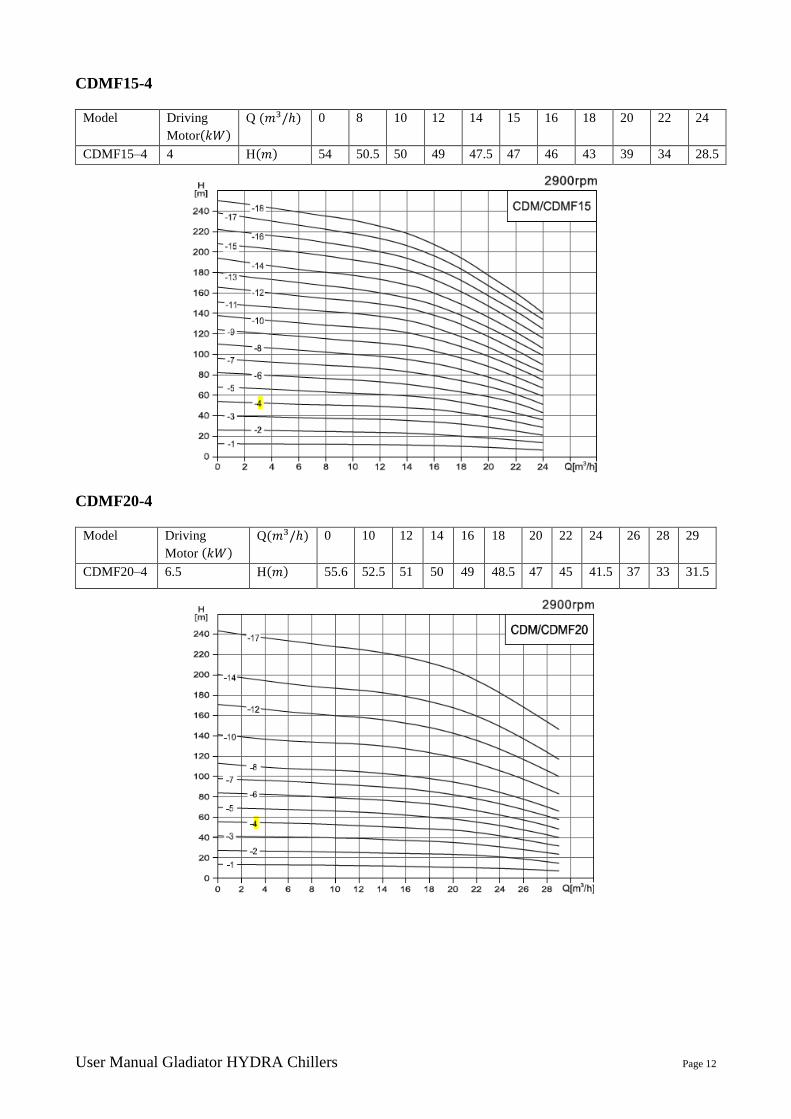
CDMF15-4
Model Driving
Motor(𝑘𝑊)
Q (𝑚3/ℎ) 0 8 10 12 14 15 16 18 20 22 24
CDMF15–4 4 H(𝑚) 54 50.5 50 49 47.5 47 46 43 39 34 28.5
CDMF20-4
Model Driving
Motor (𝑘𝑊)
Q(𝑚3/ℎ) 0 10 12 14 16 18 20 22 24 26 28 29
CDMF20–4 6.5 H(𝑚) 55.6 52.5 51 50 49 48.5 47 45 41.5 37 33 31.5
User Manual Gladiator HYDRA Chillers Page 13
Redundant Pumps
The controller monitors water flow. In the software there is a flow warning and a flow alarm. If the
flow alarm is breached then the controller will shut the pump that is running down and start the other
pump. The system will issue a warning alarm letting the operator know that the chiller has a problem
but is still running – this will be indicated by a flashing alarm rather than the solid light when there
is a full shut down. If the second pump develops a fault then the system will try to start the first pump
again. This will happen three times before a general fault is issued by the system. The system has
been plumbed so the faulty pump can be removed without shutting the unit down. The pumps have
been plumbed in such a way that the pump can be replaced without shutting the chiller down.
AQUA COOLER CONTROLLER
The chiller unit features an interface panel with LCD display and input buttons to configure certain
functions of the unit.
Unlocking the Keypad on the Aqua Cooler Controller
The key pad on the smart controller will lock out after 10 minutes of non-use. To unlock the key pad
press the [ESC], [DOWN], [UP] and [ESC] keys in sequence
OPERATIONAL LOGIC OF CONTROLLER
Start Up
Pump ON, Ball Valve OPEN (if fitted), 10 second delay and then flow readings are taken to check
pump is running normally. After compressor hold time and water temperature is above the set point
plus hysteresis, COMP1 ON. Once the water temperature reaches set point then compressor OFF.
Unit then waits for both the hysteresis and compressor hold time again and then re-starts compressor.
Temperature Control-Set Point
Controller will turn compressors off when the set point is reached. Compressors will be turned on
again once water temperature reaches set point temperature plus hysteresis.
Temperature Control-Max and Min Set Point
This prevents casual operator from setting supply temperatures too high or too low
Temperature Control-High and Low Temperature Alarm Stop
High and low temperature limits can be set in order that if they are breached then the chiller will shut
down. In rare instances a component may fail without triggering any internal fault indicators. The
User Manual Gladiator HYDRA Chillers Page 14
chiller may think it is running normally yet not refrigerating. It is recommended that high and low
temperature stop is set to yes to prevent this happening.
Fan Speed Control-Optional
The controller monitors the discharge pressure of each of the refrigeration circuits and makes
decisions for fan speed based on this value.
There are 3 ways to control the fans and the settings can be changed in the controller.
ON ZERO FULL: The fans can be set to shut down while the compressor is running If the pressure
drops below the minimum set point – say on a cold day – then the fans will shut down to prevent over
condensing even though the compressor may still be running.
ON LOW FULL (Default option): In the menu these is a valve for minimum run (default 1500 kPa)
which when reached will start the fans and run them at 20% speed. There is a fan full speed setting
(default 2200 kPa) that will run the fans at full speed. The fan speed will then run proportionally
between these two values. These operational pressures will be different for units supplied with R134a
– see the setting section of the manual
OFF FULL SP ONLY: This option haves the fans off when the compressor is off and full speed when
the compressor is on.
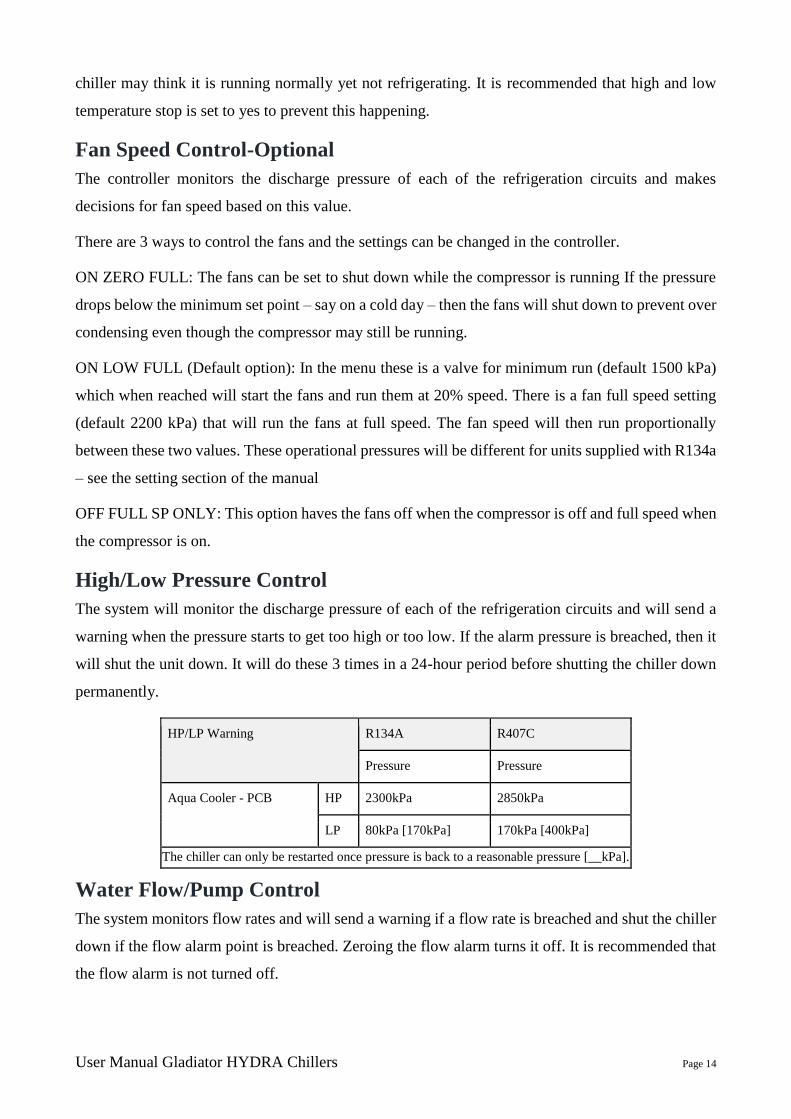
High/Low Pressure Control
The system will monitor the discharge pressure of each of the refrigeration circuits and will send a
warning when the pressure starts to get too high or too low. If the alarm pressure is breached, then it
will shut the unit down. It will do these 3 times in a 24-hour period before shutting the chiller down
permanently.
HP/LP Warning R134A R407C
Pressure Pressure
Aqua Cooler - PCB HP 2300kPa 2850kPa
LP 80kPa [170kPa] 170kPa [400kPa]
The chiller can only be restarted once pressure is back to a reasonable pressure [__kPa].
Water Flow/Pump Control
The system monitors flow rates and will send a warning if a flow rate is breached and shut the chiller
down if the flow alarm point is breached. Zeroing the flow alarm turns it off. It is recommended that
the flow alarm is not turned off.

User Manual Gladiator HYDRA Chillers Page 15
The pump can be set to run if the chiller develops a fault – by turning this feature ON in the program
will keep water to the process. This water will of course get warm but it is designed to keep the
process cool long enough for system shut down.
If the unit is supplied with a redundant pump the controller will shut the pump down when it detects
a problem with the flow. The pump sitting in redundancy with be started. If there is a problem with
the flow on this pump it will be shut down and the original pump started.
This process will happen 3 times in 24 hours before the unit is shut down permanently and every
week the pumps are duty cycled to share the wear and tear on the units
Compressor Hold Time
The controller will wait 120 seconds before starting compressors up after shut down to prevent too
many start-ups.
Alarm Acknowledge Delay
This delay is the time that the program waits before flagging an alarm. This may be useful in the event
of a tandem switch over to a tank of very warm water for example. If the water is too warm then the
high water temperature alarm may be triggered. If there is a delay then it will give the newly activated
chiller time to pull the water temperature down.
Pump Delay Time
The controller will wait for a certain time before taking flow reading – it is designed to give the ball
valve time to open before indicating flow problems
Tandem Control
One chiller will need to be assigned a master chiller and the other a slave chiller – see “CHANGING
THE CONTROLLERS PARAMETERS” section for instructions on doing this. The master chiller
will do all the controlling and timing. OUT16 (status) on the control board will be energised while it
is running closing the indicated input (enable) on the standby chiller not allowing it to run. After a
week the output will de-energise and the standby chiller will run – its OUT16 energising closing the
input on the now standby chiller. (Block diagram below)

User Manual Gladiator HYDRA Chillers Page 16
Close Tolerance
If the unit has been manufactured for close tolerance then the controller will attempt to keep the water
temperature within the close tolerance range around the midpoint between the set point and the
hysteresis.
For example if the set point is 10°C, the hystersis 2°C and the close tolerance 1°C then the controller
will attempt to keep the temperature between 10.5°C and 11.5°C. The ability of the chiller to keep
the temperature as close to the set point will vary depending on heat load. The closer the heat load is
to the chillers rated capacity the more accurate the chiller can maintain the close tolerance. Under low
loads the chiller will be unable to maintain less that 1°C close tolerance.
Putting the unit in standby mode
Using the key pad the unit can
be put into standby mode if
there is a reason to shut the
unit down for a short amount
of time.
Scroll through the menu to find “KEYPAD STANDBY”
Press “OK” and then “OK TO CONFIRM” The unit will stop running
The screen will be showing “OK TO RE-START” and “KEYPAD
STANDBY MODE” will be flashing
Press “OK” and the chiller will go through its normal start up
procedure
Note: This does not turn the unit off and the electrical circuitry inside the electrical box will still be live.
User Manual Gladiator HYDRA Chillers Page 17
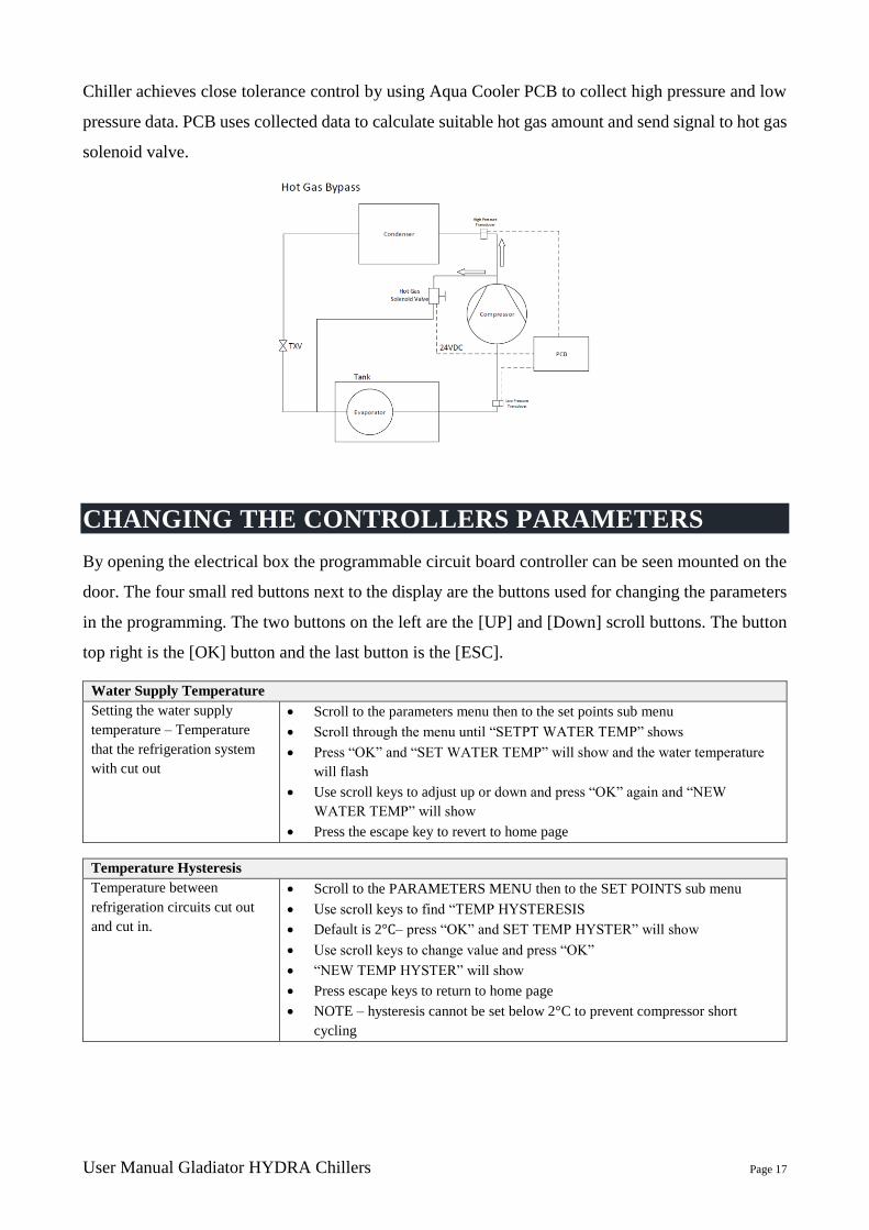
Chiller achieves close tolerance control by using Aqua Cooler PCB to collect high pressure and low
pressure data. PCB uses collected data to calculate suitable hot gas amount and send signal to hot gas
solenoid valve.
CHANGING THE CONTROLLERS PARAMETERS
By opening the electrical box the programmable circuit board controller can be seen mounted on the
door. The four small red buttons next to the display are the buttons used for changing the parameters
in the programming. The two buttons on the left are the [UP] and [Down] scroll buttons. The button
top right is the [OK] button and the last button is the [ESC].
Water Supply Temperature
Setting the water supply
temperature – Temperature
that the refrigeration system
with cut out
Scroll to the parameters menu then to the set points sub menu
Scroll through the menu until “SETPT WATER TEMP” shows
Press “OK” and “SET WATER TEMP” will show and the water temperature
will flash
Use scroll keys to adjust up or down and press “OK” again and “NEW
WATER TEMP” will show
Press the escape key to revert to home page
Temperature Hysteresis
Temperature between
refrigeration circuits cut out
and cut in.
Scroll to the PARAMETERS MENU then to the SET POINTS sub menu
Use scroll keys to find “TEMP HYSTERESIS
Default is 2°C– press “OK” and SET TEMP HYSTER” will show
Use scroll keys to change value and press “OK”
“NEW TEMP HYSTER” will show
Press escape keys to return to home page
NOTE – hysteresis cannot be set below 2°C to prevent compressor short
cycling

User Manual Gladiator HYDRA Chillers Page 18
Compressor Hold Time
After the cooler has reached
cut out temperature and the
compressor will turn off. In
order to minimise compressor
starts there is a rest time.
Range: 5 to 180 seconds
Scroll to “PARAMETER MENU” and then to the DELAY sub menu
Scroll to “COMP HOLD TIME” and press “OK”
Value will flash and can be set to minimum of 5 seconds and maximum of 3
minutes – IT IS RECOMMENDED THAT THIS VALUE IS NOT ALTERED
TO BELOW THE DEFAULT 2 MINUTES
Press “OK” and screen will confirm choice
Press the escape key to revert to home page
Maximum and Minimum Temperature Limits
This set a minimum and
maximum temperature limit
for the chiller and is there to
prevent casual operators
setting the supply temperature
above or below recommended
set points.
Range: -5°C to 20°C Min
10°C to 30°C Max
Scroll to the PARAMETERS MENU then to the SET POINTS sub menu
Scroll to “MIN TEMP LIMIT” or “MAX TEMP LIMIT”
Press “OK” and “SET MAX LIMIT” will show will value flashing
Select choice and press “OK” and the screen will confirm choice
Press the escape key to revert to home page
High and Low Temperature Stop
High and low temperature
alarm cut out – the unit can be
set to go into standby if the
high and low temperature
alarms are breached and they
will stay in standby until the
fault is cleared by pressing the
“OK” button
Range: Yes and No
Scroll to “PARAMETER MENU” then to the SYSTEM sub menu
Scroll to “HIGH TEMP STOP” and “LOW TEMP STOP” and press “OK”
“SET HI TEMP STOP” will show with “YES” and “NO” manu choices
Change as desired, press “OK” and “STOP ON HI TEMP” will show
confirming choice
Do same to change low temperature standby
Press the escape key to revert to home page
High and Low Temperature Alarm
High and low temperature
alarm cut out – the unit can be
set to go into standby if the
high and low temperature
alarms are breached and they
will stay in standby until the
fault is cleared by pressing the
“OK” button
Range: Low: -5°C to 10°C
High 10°C to 40°C
Scroll to “PARAMETER MENU” and to the SET POINTS sub menu
Scroll to “HIGH TEMP ALARM” and “LOW TEMP ALARM” and press
“OK”
“SET HI TEMP ALARM” will show temperature choices
Change as desired, press “OK” and “NEW HI TEMP ALM” will show
confirming choice
Do same to change low temperature alarm
Press the escape key to revert to home page

User Manual Gladiator HYDRA Chillers Page 19
Setting Water Flow Alarms
Setting the alarm for the
chilled water and condenser
water flow – this setting when
breached will place the unit
into standby
Range: 0-5 L/s
Scroll to “PARAMETER MENU” and to the SET POINTS sub menu
Scroll to “FLOW ALARM 1” for chilled water supply and “FLOW ALARM
2” for condenser water flow
Press “OK” and “CONFIG FL ALM1” will show with the value flashing
Change the value to where the warning needs to be and press “OK” – the alarm
rate should be below the value of the warning
The screen will confirm your choice
Press the escape key to revert to home page
Setting the waring for chilled
water and condenser water
flow. This setting will simply
give a warning that the flow
rate is dropping – the chiller
will still run.
Range: 0-5 L/s
Scroll to “PARAMETER MENU” and press “OK”
Scroll to “FLOW WARNING 1” for chilled water supply and “FLOW
WARNING 2” for condenser water flow
Press “OK” and “CONFIG FL WARN1” will show with the value flashing –
as a rough guide the flow rates for the condenser water and the chilled water
should be around 1.4 l/s
Change the value to where the warning needs to be and press “OK”
The screen will confirm your choice
Press the escape key to revert to home page
Setting High Pressure (HP) Alarms and Warnings
Controller will send out and
warning at warning pressure
and shut unit down at alarm
pressure
Range: 2000 – 4000 kPa for
both
Scroll to “PARAMETER MENU” and to the SET POINTS sub menu
Scroll to “ HP Warn Press”
Press “OK” and choices will be shown
Select choice and press “OK” and the screen will confirm choice
Press the escape key to revert to home page
Scroll to “PARAMETER MENU” and press “OK”
Scroll to “ HP ALM Press”
Press “OK” and choices will be shown
Select choice and press “OK” and the screen will confirm choice
Press the escape key to revert to home page
Setting Fan Speed Control
If fan speed controllers are
installed the minimum run
speed (20%) and max run
speed (100%) can be set again
corresponding discharge
pressures
Scroll to “PARAMETER MENU” and to the SET POINTS sub menu
Scroll to “Fan Min SP Pressure”
Press “OK” and change required pressure
Select choice and press “OK” and the screen will confirm choice
Press the escape key to revert to home page
The same procedure is followed to set “Fan Max SP pressure”
Note – of fan speed controller are being retrofitted to a unit then the fan speed
option will have to be activated in the parameters menu.
Setting Alarm Acknowledge Delay
Range 0-120 Minutes • Scroll to “PARAMETER MENU” and press “OK”
• Scroll to “ALM ACK DELAY”
• Press “OK” and change to setting
• Select choice and press “OK” and the screen will confirm choice
• Press the escape key to revert to home page
It is recommended that the setting is not greater than 1 or 2 minutes
User Manual Gladiator HYDRA Chillers Page 20
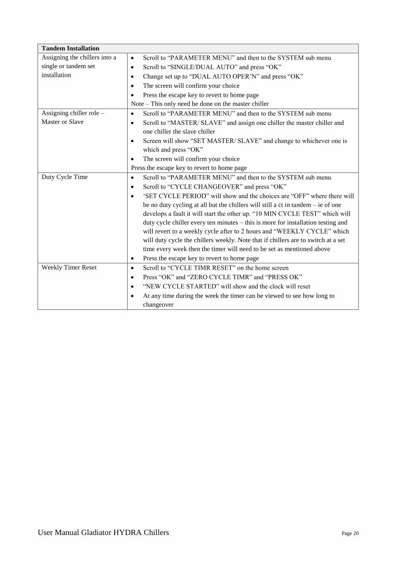
Tandem Installation
Assigning the chillers into a
single or tandem set
installation
Scroll to “PARAMETER MENU” and then to the SYSTEM sub menu
Scroll to “SINGLE/DUAL AUTO” and press “OK”
Change set up to “DUAL AUTO OPER’N” and press “OK”
The screen will confirm your choice
Press the escape key to revert to home page
Note – This only need be done on the master chiller
Assigning chiller role –
Master or Slave
Scroll to “PARAMETER MENU” and then to the SYSTEM sub menu
Scroll to “MASTER/ SLAVE” and assign one chiller the master chiller and
one chiller the slave chiller
Screen will show “SET MASTER/ SLAVE” and change to whichever one is
which and press “OK”
The screen will confirm your choice
Press the escape key to revert to home page
Duty Cycle Time Scroll to “PARAMETER MENU” and then to the SYSTEM sub menu
Scroll to “CYCLE CHANGEOVER” and press “OK”
‘SET CYCLE PERIOD” will show and the choices are “OFF” where there will
be no duty cycling at all but the chillers will still a ct in tandem – ie of one
develops a fault it will start the other up. “10 MIN CYCLE TEST” which will
duty cycle chiller every ten minutes – this is more for installation testing and
will revert to a weekly cycle after to 2 hours and “WEEKLY CYCLE” which
will duty cycle the chillers weekly. Note that if chillers are to switch at a set
time every week then the timer will need to be set as mentioned above
Press the escape key to revert to home page
Weekly Timer Reset Scroll to “CYCLE TIMR RESET” on the home screen
Press “OK” and “ZERO CYCLE TIMR” and “PRESS OK”
“NEW CYCLE STARTED” will show and the clock will reset
At any time during the week the timer can be viewed to see how long to
changeover
User Manual Gladiator HYDRA Chillers Page 21
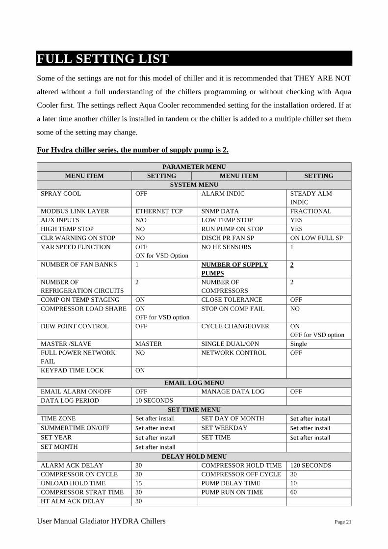
FULL SETTING LIST
Some of the settings are not for this model of chiller and it is recommended that THEY ARE NOT
altered without a full understanding of the chillers programming or without checking with Aqua
Cooler first. The settings reflect Aqua Cooler recommended setting for the installation ordered. If at
a later time another chiller is installed in tandem or the chiller is added to a multiple chiller set them
some of the setting may change.
For Hydra chiller series, the number of supply pump is 2.
PARAMETER MENU
MENU ITEM SETTING MENU ITEM SETTING
SYSTEM MENU
SPRAY COOL OFF ALARM INDIC STEADY ALM
INDIC
MODBUS LINK LAYER ETHERNET TCP SNMP DATA FRACTIONAL
AUX INPUTS N/O LOW TEMP STOP YES
HIGH TEMP STOP NO RUN PUMP ON STOP YES
CLR WARNING ON STOP NO DISCH PR FAN SP ON LOW FULL SP
VAR SPEED FUNCTION OFF
ON for VSD Option
NO HE SENSORS 1
NUMBER OF FAN BANKS 1 NUMBER OF SUPPLY
PUMPS
2
NUMBER OF
REFRIGERATION CIRCUITS
2 NUMBER OF
COMPRESSORS
2
COMP ON TEMP STAGING ON CLOSE TOLERANCE OFF
COMPRESSOR LOAD SHARE ON
OFF for VSD option
STOP ON COMP FAIL NO
DEW POINT CONTROL OFF CYCLE CHANGEOVER ON
OFF for VSD option
MASTER /SLAVE MASTER SINGLE DUAL/OPN Single
FULL POWER NETWORK
FAIL
NO NETWORK CONTROL OFF
KEYPAD TIME LOCK ON
EMAIL LOG MENU
EMAIL ALARM ON/OFF OFF MANAGE DATA LOG OFF
DATA LOG PERIOD 10 SECONDS
SET TIME MENU
TIME ZONE Set after install SET DAY OF MONTH Set after install
SUMMERTIME ON/OFF Set after install SET WEEKDAY Set after install
SET YEAR Set after install SET TIME Set after install
SET MONTH Set after install
DELAY HOLD MENU
ALARM ACK DELAY 30 COMPRESSOR HOLD TIME 120 SECONDS
COMPRESSOR ON CYCLE 30 COMPRESSOR OFF CYCLE 30
UNLOAD HOLD TIME 15 PUMP DELAY TIME 10
COMPRESSOR STRAT TIME 30 PUMP RUN ON TIME 60
HT ALM ACK DELAY 30
User Manual Gladiator HYDRA Chillers Page 22
SET POINT MENU
SETPT WATER TEMP 10 SUPPLY FLOW ALARM 1 1 l/s
SUPPLY FLOW WARNING 1 1.5 l/s LOW PR PROTECTION 350 kPa for R407c
LP HYSTERESIS PRESSURE 200 LP ALARM PRESSURE 200 with R407c
80 with R134a
LP WARNING PRESSURE 300 with R407c
100 with R134a
HI PR PROTECTION 2600 kPa
HP HYSTERESIS PRESSURE 200 HP ALARM PRESSURE 2750 with R407c
2300 with R134a
HP WARN PRESSURE 2600 with R407c
2200 with R407c
FAN MAX SPEED
PRESSURE
2200 with R407c
2000 with R134a
FAN MIN SP PRESSURE 1500 with R407c
1200 with R134a
HYST SPRAY COOL 200
HP SPRAY COOL 2600 SET PT AMB O TEMP 44
MAX TEMP LIMIT 20 MIN TEMP LIMIT 5
LOW RETURN ALARM 5 HIGH RETURN ALARM 30
LOW TEMPERATURE
ALARM
0 HIGH TEMPERATURE
ALARM
30
PID DAMPING 30 CLOSE TOLERANCE TEMP OFF
PULL DOWN PER MIN 0.6 LAST OFF HYST 0.5
TEMPERATYRE
HYSTERESIS
2
SENSOR MENU – THIS WILL VARY WITH DIFFERENT SUPPLIER SPECS
CCT1 SUCT PR SIZE 0-10 BAR SECONDARY SUPPLY CAL See Procedure
CCT1 DIS PR DISCH PR SIZE 0-40 BAR AMBIENT CAL See Procedure
SUPPLY FLOW PIPE DN 32 SECONDARY RETURN
CAL
See Procedure
User Manual Gladiator HYDRA Chillers Page 23
ADVANCED CONTROLLER FUNCTIONS
The units can use Modbus/BACnet via RS485 or TCP/IP using the Ethernet port. The default IP
address of our chillers is 10.1.1.130. So you’ll need to configure a laptop or computer to be on the
same subnet then open a web browser to the web interface at http://10.1.1.130:8076
Navigate to ‘Network’ to change the chiller’s network settings. To change between RS485 and
TCP/IP go to the controller, Parameter menu – system menu – Modbus link layer – ok – change to
your preferred protocol. The detailed steps are presented below.
If you wish to use TCP/IP and need to change the chillers IP address:
1. Connect a laptop directly to the chiller using Ethernet cable
2. Alter your PC network settings so you are on the gateway 10.1.1.1 and subnet
255.255.255.0
3. Open web browser and head to http://10.1.1.130:8076
4. Click on “Network”, it will ask for a password – username is “techcooler” and password
is “techwater”
5. Here you will see all of the chillers IP address settings etc and update as needed. Change
any settings you need and before you hit “save network confirm” put the Save Password
“aquaipconfig” without quotes into the box.
6. You can find the default chiller BACnetIP (BIP) Device Number (2012), ModBus RTU
Slave Addr (1-247) head in the Chiller ID tab. Again, use the save password
“aquacustomer” as the password.
7. Then edit the page to the new IP address details for the chiller – again ensuring you enter
the password “aquaipconfig” into the save password box.
8. Some other systems settings can be changed remotely. Go the “Control” tab and enter the
password ”aquachiller” and this will allow the user to send commands to the chiller.
DOWNLOADING DATA LOG
The chiller is automatically storing data on its operational parameters and performance. In the event
that there is a problem with the chiller this data may become useful for diagnosis.
The operational data can be downloaded from the controller by using a USB flash drive there are two
types of files on the system – and event log and a time log. The event log takes reading every time
there is an event change, compressor on or off for example. The time log saves data every set time
period. The default is every 10 minutes but this can be set as low as every 2 minutes. At 10 minutes
intervals there is over a week of data saved on the board. The parameters that are logged are the
supply, return and ambient temperatures, the suction and discharge pressures and the water flow rate.
All changes of state are also logged on the inputs and outputs. Using this data is a good way to check
the effective running of the chiller and to help with diagnosis when a service visit is needed.

User Manual Gladiator HYDRA Chillers Page 24
To Download via USB:
1. Insert a USB key into the USB key on the rear of the circuit board controller.
2. Go to the PARAMETERS MENU and press OK and then scroll to MANAGE LOG DATA
sub menu and press OK
3. There a number of options – the most useful are TIME LOG TO USB and EVENT LOG TO
USB. Press OK and the data will start to upload – the screen will confirm when the process is
complete.
4. The process has to be done twice – once for each file.
5. Putting the USB into a computer will show the folder labelled “AQUA” and inside this will
be a excel data file. The excel file will have labels for all the data that has been logged – the
newest data will be at the top.
NOTE: the shorter the time between readings the less history the system can record. 10 mins should
give approximately 3 weeks of data logging – 10 second intervals will only give 24 hours of data
logging and the logging drops the old files off the end so if the unit has a problem and it takes more
than one day to get to site then the relevant data will be gone.
The second way of downloading the data is via the webpage – to the “advanced” tab on the webpage
and then to the download tab – the drop down list will then give you the option of downloading the
files.
The controller will ask you to save the file somewhere.
Calibration of Sensors-Aqua Cooler Controller The temperature sensors will be calibrated before dispatch but in the even one needs to be replaced then it is a good idea to recalibrate
the sensors as they effect the operation of the chiller.
1. Scroll through the controller to parameters menu
2. Scroll down to the Sensor Menu sub- menu
3. Scroll through to the ambient, supply or return calibration
User Manual Gladiator HYDRA Chillers Page 25
4. Place the sensor and a calibrated thermometer together and allow the temperature to settle
5. Press OK and the value will flash. Use the up and down scroll buttons to calibrate the sensor
to the thermostat and press OK again
6. Exit the program
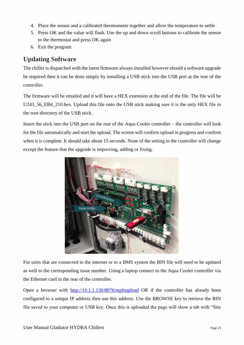
Updating Software
The chiller is dispatched with the latest firmware always installed however should a software upgrade
be required then it can be done simply by installing a USB stick into the USB port at the rear of the
controller.
The firmware will be emailed and it will have a HEX extension at the end of the file. The file will be
U243_56_EB4_210.hex. Upload this file onto the USB stick making sure it is the only HEX file in
the root directory of the USB stick.
Insert the stick into the USB port on the rear of the Aqua Cooler controller – the controller will look
for the file automatically and start the upload. The screen will confirm upload in progress and confirm
when it is complete. It should take about 15 seconds. None of the setting in the controller will change
except the feature that the upgrade is improving, adding or fixing.
For units that are connected to the internet or to a BMS system the BIN file will need to be updated
as well to the corresponding issue number. Using a laptop connect to the Aqua Cooler controller via
the Ethernet card in the rear of the controller.
Open a browser with http://10.1.1.130:8076/mpfsupload OR if the controller has already been
configured to a unique IP address then use this address. Use the BROWSE key to retrieve the BIN
file saved to your computer or USB key. Once this is uploaded the page will show a tab with “Site

User Manual Gladiator HYDRA Chillers Page 26
Main Page” on it. Click on this and it will direct you to the main monitoring page for the chiller. The
instructions are above for moving further into the control and monitoring of the chiller.
The IP address of the unit can be found by scrolling to the INFO menu on the home screen of the
controller.
In the parameter menu there is time, date and year menu lines that can be set (see the service section
for instructions) in order that the data log periods and the email alarms are time relevant.
There are other parameters in the programming menu: Some are used in some of the other options.
The setting should not be altered altering the parameters not relevant to the operation of your chiller
may affect its performance and required an out of warranty service call.
Controller Input and Output Schematic
Connector Type Control
Outputs – OUT1 to OUT16 across the top of the board.
OUT1
OUT2
OUT3
OUT4
OUT5
24VDC
1 Compressor #1
2 Compressor #2
5 Supply pump #1
6 Supply pump #2
7 Unloading valve compressor #1

User Manual Gladiator HYDRA Chillers Page 27
OUT6
OUT7
OUT8
OUT9
OUT10
OUT11
OUT12
OUT13
OUT14
MOUT1
MOUT2
MOUT3
MOUT4
OUT1 (Beside IN24)
OUT2 (Beside IN24)
OUT3 (Beside IN24)
OUT4 (Beside IN24)
0 to 10V Output
0 to 10V Output
0 to 10V Output
0 to 10V Output
8 Ball valve solenoid
9 Fan #1
10 Fan #2
11 Water spray
12 Unloading valve compressor 2
13 Master fault
14 Master run
15 BMS AUX Output
16 Tandem link enable/ Status
Stepper Motor OUT1
Stepper Motor OUT2
Stepper Motor OUT3
Stepper Motor OUT4
Pump/Comp Variable speed drive
Fan speed control – fan bank 1
Fan speed control – fan bank 2
Inputs – IN1 to IN24 across the bottom of the board.
IN1
IN2
IN5
IN6
IN9
IN10
IN11
IN12
IN13
IN16
IN17
IN18
IN19
IN20
IN21
IN22
IN23
IN24
0-10V Input
0-10V Input
0-10V NC Input
0-10V NC Input
0-10V NC Input
NTC Thermistor
NTC Thermistor
NTC Thermistor
NTC Thermistor
4-20mA Input
0-10V N/O AUX Fault Input
0-10V N/O AUX Fault Input
0-10V N/O Input
0-10V N/O Input
4-20mA input
4-20mA input
4-20mA input
4-20mA input
Supply Pump Flow Meter
Circulating Pump flow meter
Compressor 1 fault input
Compressor 2 fault input
ON/OFF Switch
Ambient temp
Chilled water supply temp
Chilled water return temperature
Plate pack safety sensor 1
Humidity sensor
Auxiliary fault input 1
Auxiliary fault input 2
Switch to allow half chiller to run on full
power – 2 compressor models only
Tandem link input
Suction pressure sensor – circuit 1
Suction pressure sensor – circuit 2
Discharge pressure sensor – circuit1
Discharge pressure sensor – circuit 2
User Manual Gladiator HYDRA Chillers Page 28
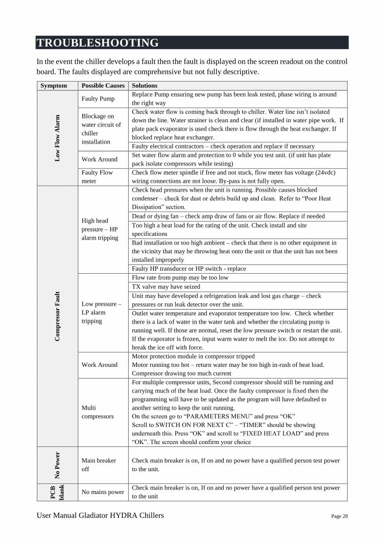
TROUBLESHOOTING
In the event the chiller develops a fault then the fault is displayed on the screen readout on the control
board. The faults displayed are comprehensive but not fully descriptive.
Symptom Possible Causes Solutions
Lo
w F
low
Ala
rm
Faulty Pump Replace Pump ensuring new pump has been leak tested, phase wiring is around
the right way
Blockage on
water circuit of
chiller
installation
Check water flow is coming back through to chiller. Water line isn’t isolated
down the line. Water strainer is clean and clear (if installed in water pipe work. If
plate pack evaporator is used check there is flow through the heat exchanger. If
blocked replace heat exchanger.
Faulty electrical contractors – check operation and replace if necessary
Work Around Set water flow alarm and protection to 0 while you test unit. (if unit has plate
pack isolate compressors while testing)
Faulty Flow
meter
Check flow meter spindle if free and not stuck, flow meter has voltage (24vdc)
wiring connections are not loose. By-pass is not fully open.
Co
mp
ress
or
Fa
ult
High head
pressure – HP
alarm tripping
Check head pressures when the unit is running. Possible causes blocked
condenser – check for dust or debris build up and clean. Refer to “Poor Heat
Dissipation” section.
Dead or dying fan – check amp draw of fans or air flow. Replace if needed
Too high a heat load for the rating of the unit. Check install and site
specifications
Bad installation or too high ambient – check that there is no other equipment in
the vicinity that may be throwing heat onto the unit or that the unit has not been
installed improperly
Faulty HP transducer or HP switch - replace
Low pressure –
LP alarm
tripping
Flow rate from pump may be too low
TX valve may have seized
Unit may have developed a refrigeration leak and lost gas charge – check
pressures or run leak detector over the unit.
Outlet water temperature and evaporator temperature too low. Check whether
there is a lack of water in the water tank and whether the circulating pump is
running well. If those are normal, reset the low pressure switch or restart the unit.
If the evaporator is frozen, input warm water to melt the ice. Do not attempt to
break the ice off with force.
Work Around
Motor protection module in compressor tripped
Motor running too hot – return water may be too high in-rush of heat load.
Compressor drawing too much current
Multi
compressors
For multiple compressor units, Second compressor should still be running and
carrying much of the heat load. Once the faulty compressor is fixed then the
programming will have to be updated as the program will have defaulted to
another setting to keep the unit running.
On the screen go to “PARAMETERS MENU” and press “OK”
Scroll to SWITCH ON FOR NEXT C” – “TIMER” should be showing
underneath this. Press “OK” and scroll to “FIXED HEAT LOAD” and press
“OK”. The screen should confirm your choice
No
Po
wer
Main breaker
off
Check main breaker is on, If on and no power have a qualified person test power
to the unit.
PC
B
bla
nk
No mains power Check main breaker is on, If on and no power have a qualified person test power
to the unit
User Manual Gladiator HYDRA Chillers Page 29
No control
voltage Check PCB has 24vdc to controller. If power is present replace PCB
C1
FL
T
Fa
ult
Safety switch
open
Check operation of safety switches (circuit that connects to input 2) Check Hp,
LP, water level switches are made. Fan/pump and compressor overloads are
made.
Work Around Bridge out components one after the other and test to see when unit doesn’t trip.
HP
Fa
ult
Faulty Fans Check operation of condenser fans. Replace if faulty.
Condenser coil
dirty Check condition of condenser is clean and air moves through freely over coil.
Ambient
Temperature to
High
Ambient temp to high. Condensing temp to be brought down. (Spray coils with
water)
Faulty
transducer Check operation of transducer/ reading correctly
LP
Fa
ult
Low refrigerant
charge
Check refrigerant system operation, check super heat and sub cooling are with in
normal operating ranges
Faulty Tx Valve Check operation of Tx valve (opening and closing as required)
Low water flow Check water flow through plate pack heat exchanger is sufficient
Water fouling Check buffer tank and coil water is clean and coil not coated in mud/debris
Faulty
transducer Check operation of transducer/reading correctly
Hig
h
Ret
urn
Wa
ter
Tem
p Faulty Probe Check probe operation/Re-calibrate sensor, replace probe
Low refrigerant
charge
Check refrigerant system operation, check super heat and sub cooling are with in
normal operating ranges
Hig
h
Su
pp
ly
Wa
ter
Tem
p Faulty probe Check operation of transducer/reading correctly
Low refrigerant
charge
Check refrigerant system operation, check super heat and sub cooling are with in
normal operating ranges
Hig
h
Am
bie
nt
Tem
p Faulty probe Check operation of transducer/reading correctly
Air Re-
circulation Check condenser air is not recirculating back over the condenser coil
Lo
w R
etu
rn
Wa
ter T
emp
Faulty probe Check operation of transducer/reading correctly
Low Water
Flow
-Check water flow through plate pack heat exchanger is sufficient
- Check pump operation. Replace pump if at fault
Low refrigerant
charge
Check refrigerant system operation, check super heat and sub cooling are with in
normal operating ranges
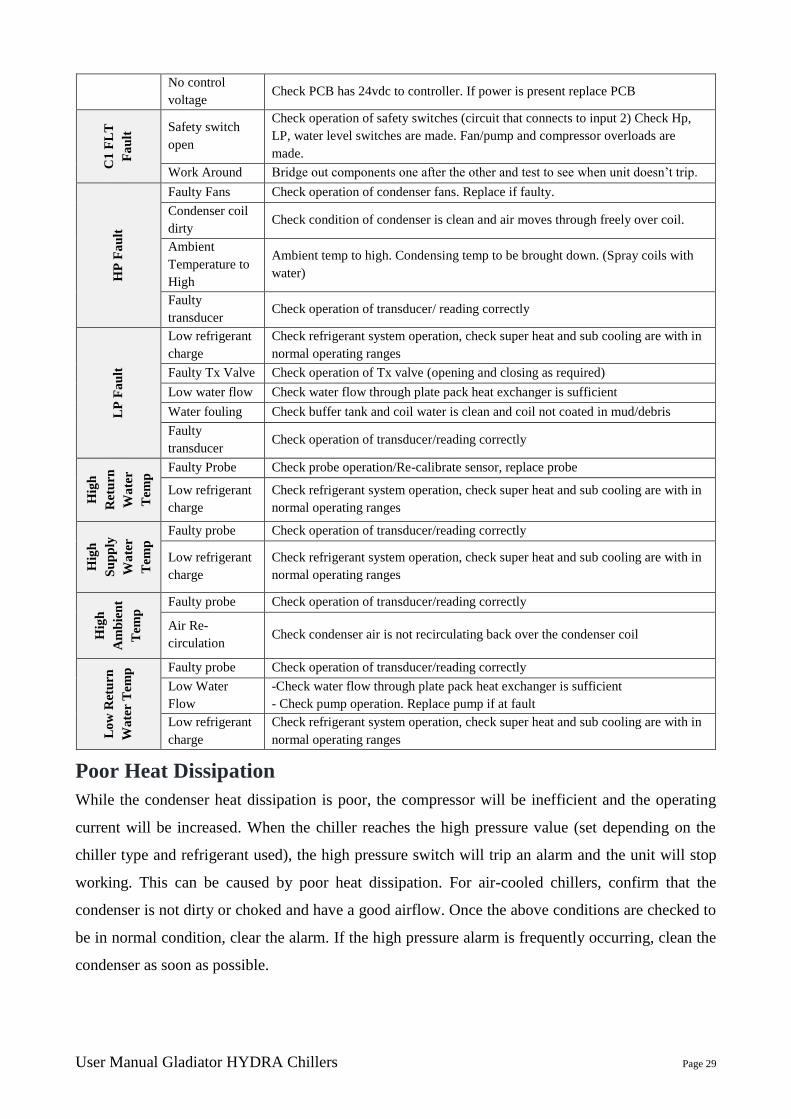
Poor Heat Dissipation
While the condenser heat dissipation is poor, the compressor will be inefficient and the operating
current will be increased. When the chiller reaches the high pressure value (set depending on the
chiller type and refrigerant used), the high pressure switch will trip an alarm and the unit will stop
working. This can be caused by poor heat dissipation. For air-cooled chillers, confirm that the
condenser is not dirty or choked and have a good airflow. Once the above conditions are checked to
be in normal condition, clear the alarm. If the high pressure alarm is frequently occurring, clean the
condenser as soon as possible.
User Manual Gladiator HYDRA Chillers Page 30
Low Refrigerant
If the pressure at the gauge is pressure low, it may indicate a shortage of refrigerant. Any leaks should
be filled, the dryer filter should be changed, and it should be drawing a vacuum again. Refill the
refrigerant after the above has been performed.
If the leaking part is within water, stop the chiller immediately and discharge the water in the water
tank quickly. The compressor can be damaged badly if it sucks in water.
Low and High Pressure Difference
While the compressor is running, if the difference between high pressure and low pressure is small,
it may indicate the piston inside the compressor is damaged. If this is detected, the unit should be
stopped immediately. It is normal for the pressures to be similar if the compressor is not running.
Compressor Not Starting
If the fault indicator and the protection switch are normal, but the compressor will not start, please
check the following:
1. The set temperature is too high or the temperature sensor is damaged
2. The PCB button is damaged
3. The anti-freezing switch is damaged
4. The pressure switch is damaged
5. The overload protector of the compressor is damaged
6. The electromagnetic relay is damaged or the overload protector is damaged
7. The water level is too low
8. The refrigerating water protecting switch is damaged
MAINTENANCE
Warning:
- Always isolate the power from the chiller prior to working on the unit.
- Always ensure that personnel have read and understood the SAFETY section of this manual
prior to working on the chiller.
- When the mains controller is de-energised the power contactors are live, even if the
components are not operating. All maintenance must be carried out by qualified refrigeration
mechanics.
These units have been designed for the minimum of maintenance. However to ensure optimum
performance qualified personnel should carry out regular maintenance. A comprehensive
preventative maintenance program is available through Aqua Cooler carried out by qualified
refrigeration mechanics. If there is any fault or concern during daily operation, please contact Aqua
Cooler to arrange a service call.

User Manual Gladiator HYDRA Chillers Page 31
Recommended Preventative Maintenance Program
A comprehensive preventative maintenance section is included in the back of this manual
Operation Frequency
Refrigerant Charge 6 Monthly
Electrical connections are tight 6 Monthly
Compressor amp draw 12 Monthly
Pump amp draw 12 Monthly
Condenser strainer cleaned 6 Monthly
WARRANTY
Any claim under this warranty must be made within the discussed time period of the date of purchase
of the product. To make a claim under the warranty, return the product (with proof of purchase) to
the supplier where you purchased the product or contact Aqua Cooler regarding warranty conditions.
Aqua Cooler will pay your reasonable, direct expenses of claiming under this warranty. You may
submit details and proof of your expense claim to Aqua Cooler Pty Ltd for consideration. This
warranty is given by Aqua Cooler Pty Ltd, U14, 2-12 Knobel Court Shailer Park 4128 QLD.
This warranty is provided in addition to other rights and remedies you have under law: Our goods
come with guarantees which cannot be excluded under Australian Consumer Law. You are entitled
to replacement or refund for a major failure and to compensation for other reasonably foreseeable
loss or damage. You are also entitled to have the goods repaired or replaced if the goods fail to be of
acceptable quality and the failure does not amount to a major failure.
A comprehensive commissioning procedure is attached in the end of the manual. This must be carried
out in accordance with the procedure and returned to Aqua Cooler at [email protected].
Aqua Cooler offers a commissioning program and can arrange this for you. Failing to follow the
commissioning procedure may void this warranty.
GENERAL APPLICATION
The chiller is designed to refrigerate and circulate water to a heat developing process to aid in keeping
that process cool. They are supplied with an immersed coiled copper evaporator, or plate heat
exchanger, or shell&tube evaporator (model dependant) an air cooled condenser and a scroll
compressor to circulate the refrigerant gas. Water is circulated out of the unit via a pump. The chiller
is design to be installed outdoors and refrigerate water for a heat developing process – not for drinking
or food preparation purposes. Any other use of this water chiller is a not as it is intended.

User Manual Gladiator HYDRA Chillers Page 32
Installation Sketch Map of Air Cooled Chiller

User Manual Gladiator HYDRA Chillers Page 33
Installation Sketch Map of Water Cooled Chiller

User Manual Gladiator HYDRA Chillers Page 34
Internal Structure Sketch Map of Air Cooled Chiller
HYDRA series have two compressors (two refrigeration circuits) and two pumps (two water circuits)
for redundancy.
User Manual Gladiator HYDRA Chillers Page 35
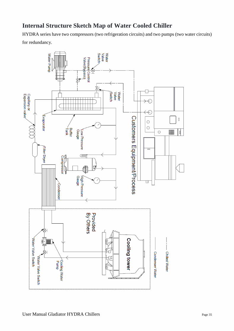
Internal Structure Sketch Map of Water Cooled Chiller
HYDRA series have two compressors (two refrigeration circuits) and two pumps (two water circuits)
for redundancy.
User Manual Gladiator HYDRA Chillers Page 36
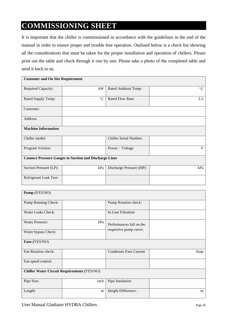
COMMISSIONING SHEET
It is important that the chiller is commissioned in accordance with the guidelines in the end of the
manual in order to ensure proper and trouble free operation. Outlined below is a check list showing
all the considerations that must be taken for the proper installation and operation of chillers. Please
print out the table and check through it one by one. Please take a photo of the completed table and
send it back to us.
Customer and On Site Requirement
Required Capacity: kW Rated Ambient Temp: C
Rated Supply Temp: C Rated Flow Rate: L/s
Customer:
Address:
Machine Information
Chiller model: Chiller Serial Number:
Program Version: Power – Voltage V
Connect Pressure Gauges to Suction and Discharge Lines
Suction Pressure (LP): kPa Discharge Pressure (HP): kPa
Refrigerant Leak Test:
Pump (YES/NO)
Pump Running Check: Pump Rotation check:
Water Leaks Check: In Line Filtration:
Water Pressure: kPa Performances fall on the
respective pump curve:
Water bypass Check:
Fans (YES/NO)
Fan Rotation check: Condenser Fans Current Amp
Fan speed control:
Chiller Water Circuit Requirements (YES/NO)
Pipe Size: inch Pipe Insulation:
Length: m Height Difference: m

User Manual Gladiator HYDRA Chillers Page 37
Balancing Valve:
Isolation Valves:
Water Treatment:
Make Up Water:
Treatment Used and
Others Notes:
Operation Testing: (YES/NO)
Ambient Temp: C Water Set Point: C
Temp Controller
Reading Check:
Fault Buzzer/Light
Works:
Sight Glass Clear: Unit Handles Heat Load:
On/Off Button Works: Check Oil level on the
compressor sight glass.
Operation Testing – Current:
Chiller Running
Current: Amp Pump 1 Current Amp
Compressor 1 Current: Amp Pump 2 Current (if fitted) Amp
Compressor 2 Current
(if fitted) Amp
Redundant pump
(if fitted)
Amp
Pump 1 Flow Rate: L/s Condenser Fans Current Amp
Pump 2 Flow Rate:
(if fitted)
L/s
Installation and Build Check (YES/NO)
Any damage from transport Adequate clearance around and above
Electrical isolation switch Inside chiller clean
Panels are clean All settings to factory default
Pipes to the process All marking in place
Panels secure Electrical wiring is tight
Electrical box secure Electrical box tidy
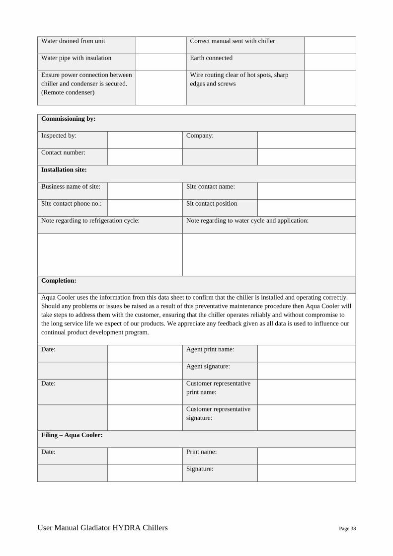
User Manual Gladiator HYDRA Chillers Page 38
Water drained from unit Correct manual sent with chiller
Water pipe with insulation Earth connected
Ensure power connection between
chiller and condenser is secured.
(Remote condenser)
Wire routing clear of hot spots, sharp
edges and screws
Commissioning by:
Inspected by: Company:
Contact number:
Installation site:
Business name of site: Site contact name:
Site contact phone no.: Sit contact position
Note regarding to refrigeration cycle: Note regarding to water cycle and application:
Completion:
Aqua Cooler uses the information from this data sheet to confirm that the chiller is installed and operating correctly.
Should any problems or issues be raised as a result of this preventative maintenance procedure then Aqua Cooler will
take steps to address them with the customer, ensuring that the chiller operates reliably and without compromise to
the long service life we expect of our products. We appreciate any feedback given as all data is used to influence our
continual product development program.
Date: Agent print name:
Agent signature:
Date: Customer representative
print name:
Customer representative
signature:
Filing – Aqua Cooler:
Date: Print name:
Signature:

User Manual Gladiator HYDRA Chillers Page 39
NOTES