glass ceramics
TRANSCRIPT
ME 3701, Material of Engineering Laboratory, LSU1
Experiment: "Ceramics"
Objective
The primary objective of this study is to gain an understanding of the mechanical properties, and underlyingatomic structures that cause the properties, of ceramic materials through application of Modulus of Rupture tests.
Abstract
The primary drawback of using ceramic materials in structural applications is their inherent brittleness whichresults from strong bonding coupled with electrical balancing restrictions due to the metallic plus non-metallicnature of ceramic compounds. The Modulus of Rupture (MOR) test is the standard for determining themechanical properties of ceramics (Flexural Strength and Flexural Modulus). Variations in Flexural Strengthas a function of firing temperature and specimen size will be examined experimentally (MOR) and evaluatedusing the statistical t-test; large ceramic parts generally have lower strengths due to their higher probability ofcontaining critical flaws.
Background
Ceramics are generally composed of Metallic + Non-Metallic Compounds which are primarily IonicallyBonded.
Silicon and Oxygen are Common in Ceramics due to Availability and Cost.
Common Structural Ceramics include Silicon Oxides, Nitrides and Carbides which include clay minerals suchas pottery, tiles, cement and glass.
General Ceramic Properties:
Insulative, Refractory, Hard and Brittle.
Advanced Ceramic Applications:
• High-Temperature Engines.
• Tools for Machining Hard Metallics.
• Coatings that Require High-Temperature Resistance and Chemical Stability (Enamels).
• Optical uses include: Lasers, Florescent Screens and Iridescent Films.
Brittleness is the Primary Drawback of Ceramics; Ceramic Compounds are being developed which exhibitmeasurable ductility with excellent strength and hardness.
Three General Categories of Ceramics:
1. Crystalline Ceramics include Silicates, Oxides and Non-Oxide Compounds which form crystallinesolids and are utilized in pottery, bricks and many high-tech industries such as aerospace andelectronics.
2. Glasses include Silicate and Non-Silicate Compounds which are non-crystalline; Glasses aregenerally Amorphous.
3. Glass-Ceramics are composed of crystalline ceramics that are initially formed as glasses and aresubsequently crystallized under controlled thermal processing.
ME 3701, Material of Engineering Laboratory, LSU2
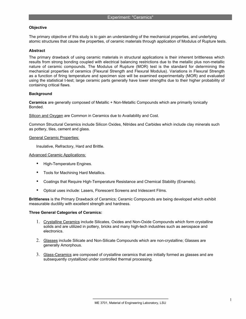
Figure 1 - (a) Crystalline Ceramic Structure, (b) Amorphous Ceramic Structure. [Askeland, 1996]
Crystalline Ceramics
Most Crystalline Ceramics are SiOi2 based and are termed Silicates.
Silicate Examples: Pottery, Whiteware, Bricks, Tile.
Table 1 - Compositions of some Silicate Ceramics. [Shackelford, 1992]
Note that Silicate Ceramics are generally Oxides!
Crystalline Ceramic Formation involves Firing which refers to controlled heating that Dries and Facilitates IonicBonding of the Compounds.
Ceramic Strength is highly dependent on Porosity (size and number of voids) which act as crack initiation sites.Crystalline Ceramics are influenced by the Nature of the Component Ions:
• Crystals must be Electrically Balanced thus Compositions must be Balanced!• Relative Ion Size generally determines the Crystalline Structures that form.
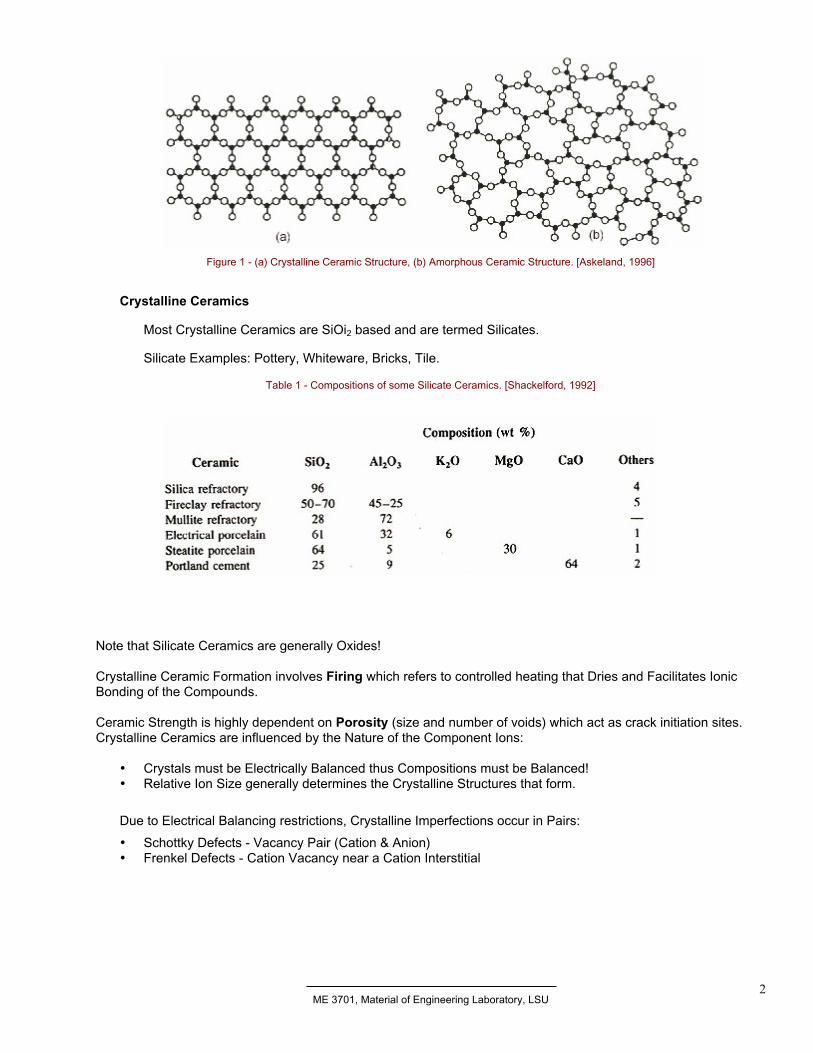
Due to Electrical Balancing restrictions, Crystalline Imperfections occur in Pairs:
• Schottky Defects - Vacancy Pair (Cation & Anion)• Frenkel Defects - Cation Vacancy near a Cation Interstitial
ME 3701, Material of Engineering Laboratory, LSU3
Figure 2 - Illustrations of Frankel and schottky defects. [Callister, 1991]
Electrical Balancing Restrictions are also partially responsible for Ceramic Brittleness; Dislocation Movement andPlastic Deformation are minimal.
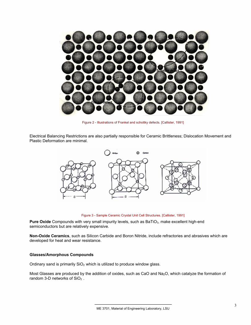
Figure 3 - Sample Ceramic Crystal Unit Cell Structures. [Callister, 1991]
Pure Oxide Compounds with very small impurity levels, such as BaTiO3, make excellent high-endsemiconductors but are relatively expensive.
Non-Oxide Ceramics, such as Silicon Carbide and Boron Nitride, include refractories and abrasives which aredeveloped for heat and wear resistance.
Glasses/Amorphous Compounds
Ordinary sand is primarily SiO2 which is utilized to produce window glass.
Most Glasses are produced by the addition of oxides, such as CaO and Na2O, which catalyze the formation ofrandom 3-D networks of SiO2 .
ME 3701, Material of Engineering Laboratory, LSU4
Table 2 - Compositions of some Silicate Ceramics. [Shackelford, 1992]
Examples of Common Non-Crystalline Ceramics
Vitreous Silica is relatively pure SiO2 which can withstand temperatures up to 1000oC; typically utilized infurnace windows.
E-Glass and S-Glass are thin pultruded fibers utilized in Composites.
Enamel is a ceramic coating applied for Temperature & Corrosion Protection.
Window Glass is a mixture of Oxides; 72% SiO2 with Na2O, CaO, MgO and Al2O3.
Glass Ceramics
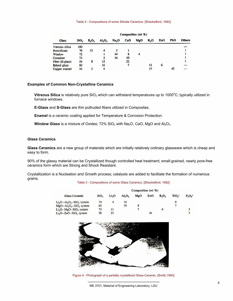
Glass Ceramics are a new group of materials which are initially relatively ordinary glassware which is cheap andeasy to form.
90% of the glassy material can be Crystallized though controlled heat treatment; small-grained, nearly pore-freeceramics form which are Strong and Shock Resistant.
Crystallization is a Nucleation and Growth process; catalysts are added to facilitate the formation of numerousgrains.
Table 3 - Compositions of some Glass Ceramics. [Shackelford, 1992]
Figure 4 - Photograph of a partially crystallized Glass-Ceramic. [Smith,1993]
ME 3701, Material of Engineering Laboratory, LSU5
Bend Test - Modules of Rupture
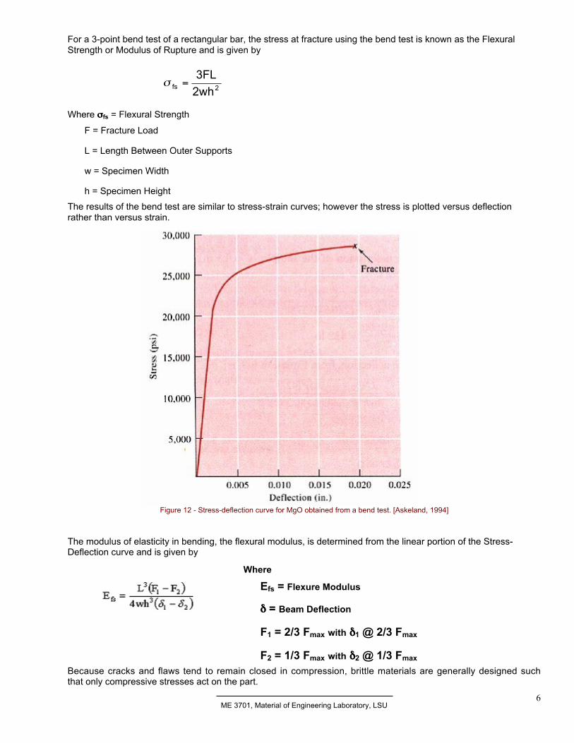
In ductile materials, the stress-strain behavior is found by applying the tensile test (as determined in previousexperiments). The curve typically goes through a maximum which is where the tensile strength is located.Failure occurs at a lower stress after necking has reduced the cross-sectional area supporting the load. Onthe other hand the stress-strain behavior of brittle ceramics is not ascertained by a tensile test. There aremany reasons the tensile test is not used:
1. it is difficult to prepare and test specimens having the required geometry;
2. it is difficult to grip brittle materials without fracturing them;
3. surface flaws often cause premature failures; and
4. ceramics fail after only about 0.1% strain thus specimens must be perfectly aligned in order toavoid the presence of bending stresses.
For these reasons a more suitable transverse bending test is used.
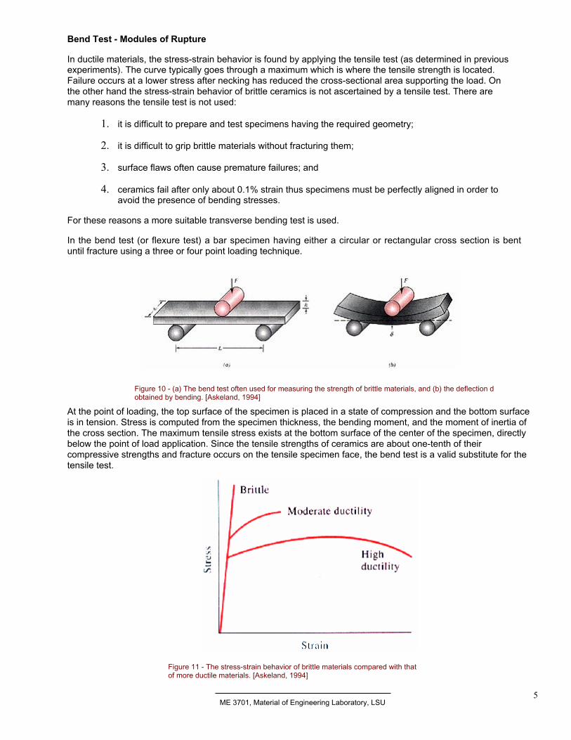
In the bend test (or flexure test) a bar specimen having either a circular or rectangular cross section is bentuntil fracture using a three or four point loading technique.
Figure 10 - (a) The bend test often used for measuring the strength of brittle materials, and (b) the deflection dobtained by bending. [Askeland, 1994]
At the point of loading, the top surface of the specimen is placed in a state of compression and the bottom surfaceis in tension. Stress is computed from the specimen thickness, the bending moment, and the moment of inertia ofthe cross section. The maximum tensile stress exists at the bottom surface of the center of the specimen, directlybelow the point of load application. Since the tensile strengths of ceramics are about one-tenth of theircompressive strengths and fracture occurs on the tensile specimen face, the bend test is a valid substitute for thetensile test.
Figure 11 - The stress-strain behavior of brittle materials compared with thatof more ductile materials. [Askeland, 1994]
ME 3701, Material of Engineering Laboratory, LSU6
For a 3-point bend test of a rectangular bar, the stress at fracture using the bend test is known as the FlexuralStrength or Modulus of Rupture and is given by
Where σσσσfs = Flexural Strength
F = Fracture Load
L = Length Between Outer Supports
w = Specimen Width
h = Specimen Height
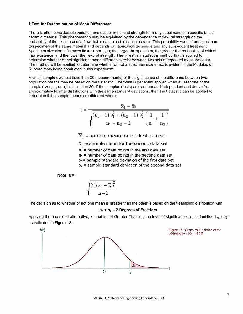
The results of the bend test are similar to stress-strain curves; however the stress is plotted versus deflectionrather than versus strain.
Figure 12 - Stress-deflection curve for MgO obtained from a bend test. [Askeland, 1994]
The modulus of elasticity in bending, the flexural modulus, is determined from the linear portion of the Stress-Deflection curve and is given by
Because cracks and flaws tend to remain closed in compression, brittle materials are generally designed suchthat only compressive stresses act on the part.
2fs 2wh
3FL=σ
Where
Efs = Flexure Modulus
δδδδ = Beam Deflection
F1 = 2/3 Fmax with δδδδ1 @ 2/3 Fmax
F2 = 1/3 Fmax with δδδδ2 @ 1/3 Fmax
ME 3701, Material of Engineering Laboratory, LSU7
t-Test for Determination of Mean Differences
There is often considerable variation and scatter in flexural strength for many specimens of a specific brittleceramic material. This phenomenon may be explained by the dependence of flexural strength on theprobability of the existence of a flaw that is capable of initiating a crack. This probability varies from specimento specimen of the same material and depends on fabrication technique and any subsequent treatment.Specimen size also influences flexural strength; the larger the specimen, the greater the probability of criticalflaw existence, and the lower the flexural strength. The t-Test is a statistical method that is applied todetermine whether or not significant mean differences exist between two sets of repeated measures data.The method will be applied to determine whether or not a specimen size effect is evident in the Modulus ofRupture tests being conducted in this experiment.
A small sample-size test (less than 30 measurements) of the significance of the difference between twopopulation means may be based on the t statistic. The t-test is generally applied when at least one of thesample sizes, n1 or n2, is less than 30. If the samples (tests) are random and independent and derive fromapproximately Normal distributions with the same standard deviations, then the t statistic can be applied todetermine if the sample means are different where:
n1 = number of data points in the first data setn2 = number of data points in the second data sets1 = sample standard deviation of the first data sets2 = sample standard deviation of the second data set
Note: s =
The decision as to whether or not one mean is greater than the other is based on the t-sampling distribution with
n1 + n2 – 2 Degrees of Freedom.
Applying the one-sided alternative, 1x that is not Greater Than 2x , the level of significance, α, is identified t α/2 by
as indicated in Figure 13.
set data first the for mean sample =1X
set data second the for mean sample =2X
Figure 13 - Graphical Depiction of thet-Distribution. [Ott, 1988]
ME 3701, Material of Engineering Laboratory, LSU8
The following procedure can be utilized in the application of the t-test:
1. State the Null Hypothesis as HO: 1x Not Greater Than 2x
2. State the Alternative Hypothesis as HA: 1x Greater Than 2x
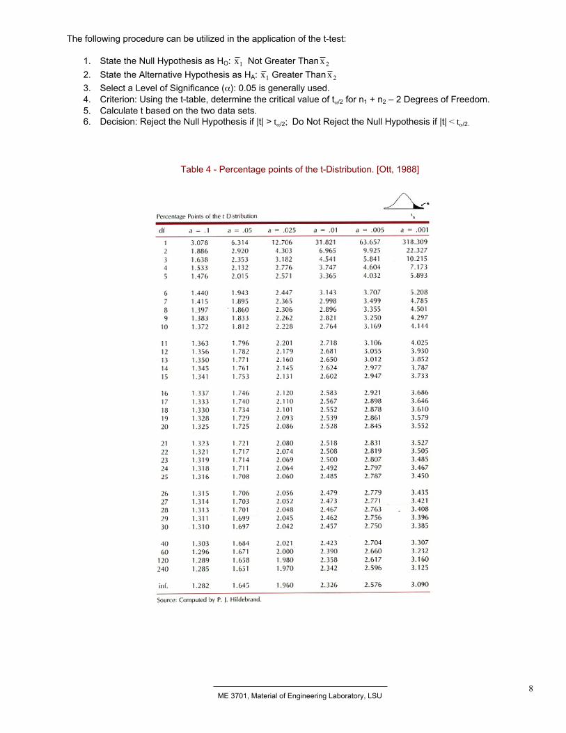
3. Select a Level of Significance (α): 0.05 is generally used.4. Criterion: Using the t-table, determine the critical value of tα/2 for n1 + n2 – 2 Degrees of Freedom.5. Calculate t based on the two data sets.6. Decision: Reject the Null Hypothesis if |t| > tα/2; Do Not Reject the Null Hypothesis if |t| < tα/2.
Table 4 - Percentage points of the t-Distribution. [Ott, 1988]
ME 3701, Material of Engineering Laboratory, LSU9
Example: Two sets of tensile strength test data were collected as indicated below. It is thought that Zinc Coatedparts are stronger than Tin Coated parts. Use the 0.05 Level of Significance to determine whether the MeanStrength of the Zinc Coated parts can be considered to be Greater Than the Mean Strength of the Ting Coatedparts.
Tin Coated Parts – Tensile Stength (MPa): 55, 56, 49, 61, 58
Zinc Coated Parts – Tensile Strength (MPa): 62, 63, 53, 59, 60
Answer: t = 5.404, tα/2 = 2.306 -> Reject Ho ( 1x Not Greater Than 2x ) -> Accept HA ( 1x Greater Than 2x )
Ceramic Properties
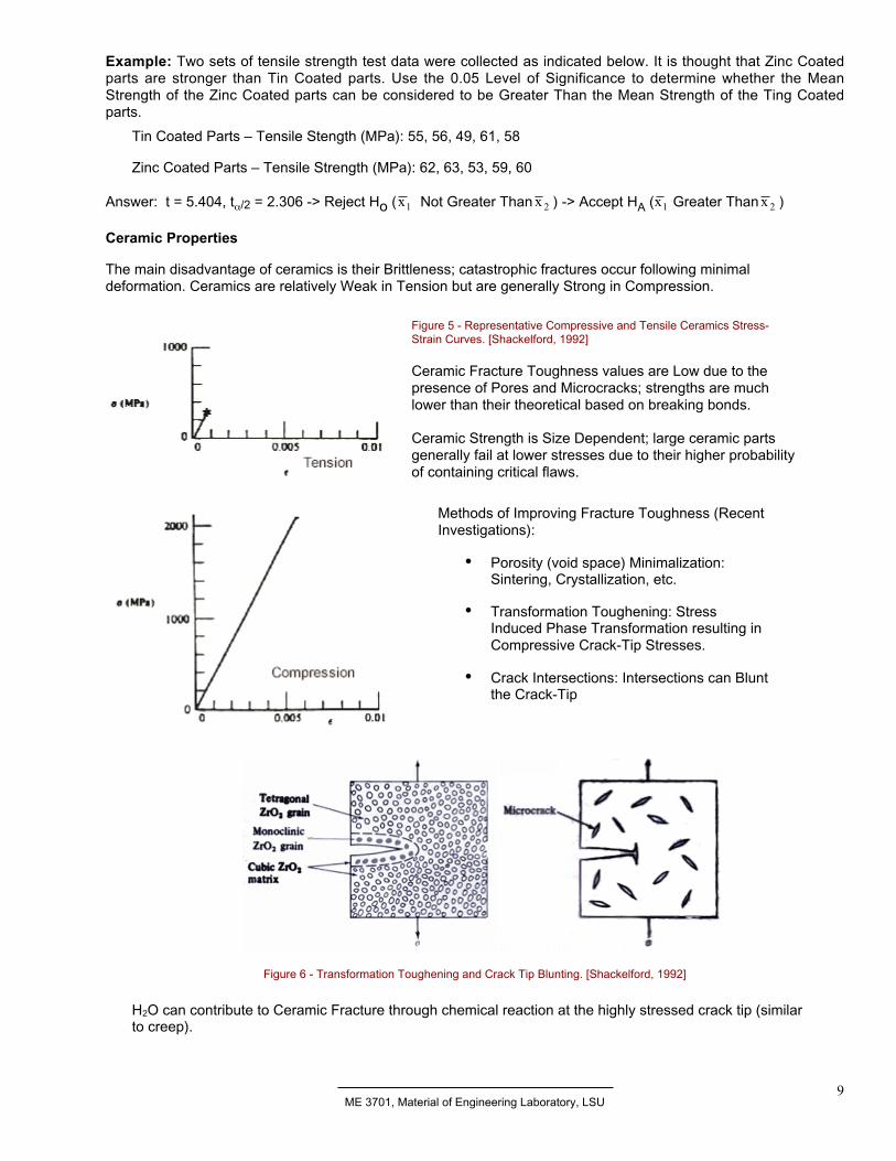
The main disadvantage of ceramics is their Brittleness; catastrophic fractures occur following minimaldeformation. Ceramics are relatively Weak in Tension but are generally Strong in Compression.
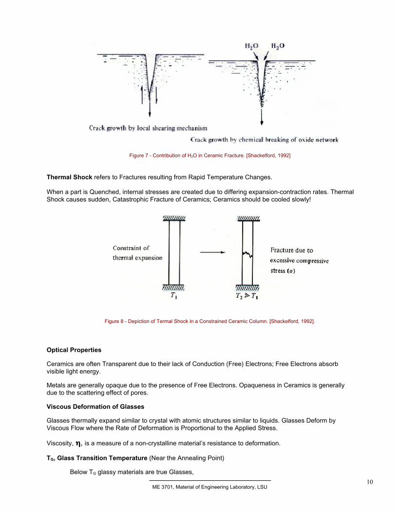
Figure 6 - Transformation Toughening and Crack Tip Blunting. [Shackelford, 1992]
H2O can contribute to Ceramic Fracture through chemical reaction at the highly stressed crack tip (similarto creep).
Figure 5 - Representative Compressive and Tensile Ceramics Stress-Strain Curves. [Shackelford, 1992]
Ceramic Fracture Toughness values are Low due to thepresence of Pores and Microcracks; strengths are muchlower than their theoretical based on breaking bonds.
Ceramic Strength is Size Dependent; large ceramic partsgenerally fail at lower stresses due to their higher probabilityof containing critical flaws.
Methods of Improving Fracture Toughness (RecentInvestigations):
• Porosity (void space) Minimalization:Sintering, Crystallization, etc.
• Transformation Toughening: StressInduced Phase Transformation resulting inCompressive Crack-Tip Stresses.
• Crack Intersections: Intersections can Bluntthe Crack-Tip
ME 3701, Material of Engineering Laboratory, LSU10
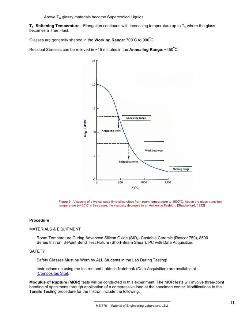
Figure 7 - Contribution of H2O in Ceramic Fracture. [Shackelford, 1992]
Thermal Shock refers to Fractures resulting from Rapid Temperature Changes.
When a part is Quenched, internal stresses are created due to differing expansion-contraction rates. ThermalShock causes sudden, Catastrophic Fracture of Ceramics; Ceramics should be cooled slowly!
Figure 8 - Depiction of Termal Shock in a Constrained Ceramic Column. [Shackelford, 1992].
Optical Properties
Ceramics are often Transparent due to their lack of Conduction (Free) Electrons; Free Electrons absorbvisible light energy.
Metals are generally opaque due to the presence of Free Electrons. Opaqueness in Ceramics is generallydue to the scattering effect of pores.
Viscous Deformation of Glasses
Glasses thermally expand similar to crystal with atomic structures similar to liquids. Glasses Deform byViscous Flow where the Rate of Deformation is Proportional to the Applied Stress.
Viscosity, ηηηη, is a measure of a non-crystalline material’s resistance to deformation.
TG, Glass Transition Temperature (Near the Annealing Point)
Below TG glassy materials are true Glasses,
ME 3701, Material of Engineering Laboratory, LSU11
Above TG glassy materials become Supercooled Liquids.
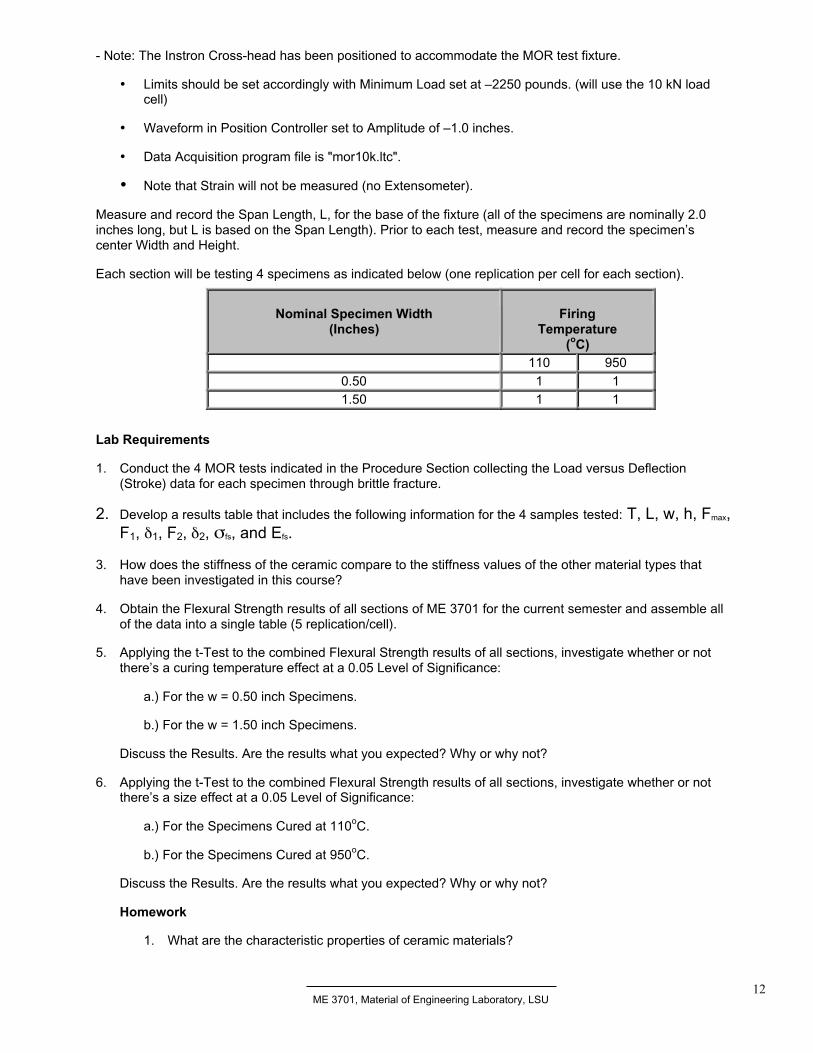
TS, Softening Temperature - Elongation continues with increasing temperature up to TS where the glassbecomes a True Fluid.
Glasses are generally shaped in the Working Range: 700oC to 900
oC.
Residual Stresses can be relieved in ~15 minutes in the Annealing Range: ~450oC.
Figure 9 - Viscosity of a typical soda-lime-silica glass from room temperature to 15000C. Above the glass transitiontemperature (~4500C in this case), the viscosity decrease in an Arrhenius Fashion. [Shackelford, 1992]
Procedure
MATERIALS & EQUIPMENT
Room Temperature Curing Advanced Silicon Oxide (SiO2) Castable Ceramic (Rescor 750), 8500Series Instron, 3-Point Bend Test Fixture (Short-Beam Shear), PC with Data Acquisition.
SAFETY
Safety Glasses Must be Worn by ALL Students in the Lab During Testing!
Instructions on using the Instron and Labtech Notebook (Data Acquisition) are available at[Composites Site].
Modulus of Rupture (MOR) tests will be conducted in this experiment. The MOR tests will involve three-pointbending of specimens through application of a compressive load at the specimen center. Modifications to theTensile Testing procedure for the Instron include the following:
ME 3701, Material of Engineering Laboratory, LSU12
- Note: The Instron Cross-head has been positioned to accommodate the MOR test fixture.
• Limits should be set accordingly with Minimum Load set at –2250 pounds. (will use the 10 kN loadcell)
• Waveform in Position Controller set to Amplitude of –1.0 inches.
• Data Acquisition program file is "mor10k.ltc".
• Note that Strain will not be measured (no Extensometer).
Measure and record the Span Length, L, for the base of the fixture (all of the specimens are nominally 2.0inches long, but L is based on the Span Length). Prior to each test, measure and record the specimen’scenter Width and Height.
Each section will be testing 4 specimens as indicated below (one replication per cell for each section).
Nominal Specimen Width(Inches)
FiringTemperature
(oC)110 950
0.50 1 11.50 1 1
Lab Requirements
1. Conduct the 4 MOR tests indicated in the Procedure Section collecting the Load versus Deflection(Stroke) data for each specimen through brittle fracture.
2. Develop a results table that includes the following information for the 4 samples tested: T, L, w, h, Fmax,F1, δ1, F2, δ2, σfs, and Efs.
3. How does the stiffness of the ceramic compare to the stiffness values of the other material types thathave been investigated in this course?
4. Obtain the Flexural Strength results of all sections of ME 3701 for the current semester and assemble allof the data into a single table (5 replication/cell).
5. Applying the t-Test to the combined Flexural Strength results of all sections, investigate whether or notthere’s a curing temperature effect at a 0.05 Level of Significance:
a.) For the w = 0.50 inch Specimens.
b.) For the w = 1.50 inch Specimens.
Discuss the Results. Are the results what you expected? Why or why not?
6. Applying the t-Test to the combined Flexural Strength results of all sections, investigate whether or notthere’s a size effect at a 0.05 Level of Significance:
a.) For the Specimens Cured at 110oC.
b.) For the Specimens Cured at 950oC.
Discuss the Results. Are the results what you expected? Why or why not?
Homework
1. What are the characteristic properties of ceramic materials?
ME 3701, Material of Engineering Laboratory, LSU13
2. What is the primary difficulty of using ceramics in structural applications and what are some of themethods applied to overcome this difficulty.
3. Why would a ceramic with large pores be expected to be weaker than an equivalent ceramic withsmall pores?
4. Briefly explain why Ceramics tend to be Electrically Insulative and Non-Corrosive.
5. If Dislocations are so important in Metals, why are they Not Important in Ceramics?
6. What is Thermal Shock?
7. What is the purpose of the t-test in this experiment?
8. Why would we expect larger ceramic specimens to fail at lower stress levels?
9. What occurs during the Firing of Ceramic materials?
10. Where would you expect failure to initiate in a Modulus of Rupture test using a 3-Point-Bend testfixture. Briefly explain your answer.