glass in energy glasses for fuel cells and h2 storage · glass in energy glasses for fuel cells and...
TRANSCRIPT
Rui M. Almeida Glass in energy Spring 2012 1
Glass in energy
Glasses for fuel cells
and H2 storage
MAT 498
Lehigh University
Rui M. Almeida Glass in energy Spring 2012 2
Fuel cells
Rui M. Almeida Glass in energy Spring 2012 3
Fuel cells and the hydrogen economy
Fuel cells (FCs) achieve the direct conversion of chemical to electrical energy and
will certainly find widespread use as they have very high efficiencies, may use
common fuels and can reduce CO2 emissions, at zero noise level, to improve the
environment. A primitive fuel cell was demonstrated ~ 160 yrs ago.
Compared to the existing internal combustion engines such as gasoline and diesel,
FCs can provide higher generating efficiency between ~ 30 – 60 %. Besides, they
practically emit no CO2 nor other exhaust gases, thus drawing much attention as an
environment-friendly, next-generation power generating system.
Most FCs used H2 as the fuel. Although the introduction of the H2 economy may
seem attractive, the cheapest technology for large scale production of hydrogen is
the steam reforming of natural gas, which produces significant emissions of
greenhouse gases. And the problem of H2 storage is also not solved yet.
For FCs to become widely used one will need optimal choice of fuel and
development of alternative materials in the FC stack. Present FC prototypes still use
materials selected more than 30 years ago.
Rui M. Almeida Glass in energy Spring 2012 4
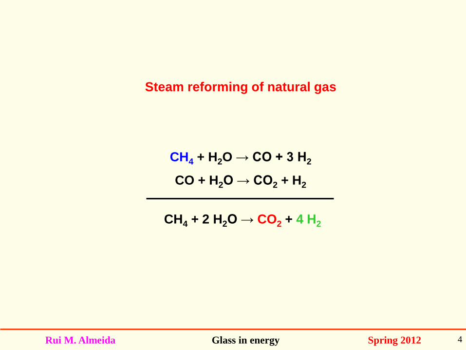
Steam reforming of natural gas
CH4 + H2O → CO + 3 H2
CO + H2O → CO2 + H2
CH4 + 2 H2O → CO2 + 4 H2
Rui M. Almeida Glass in energy Spring 2012 5
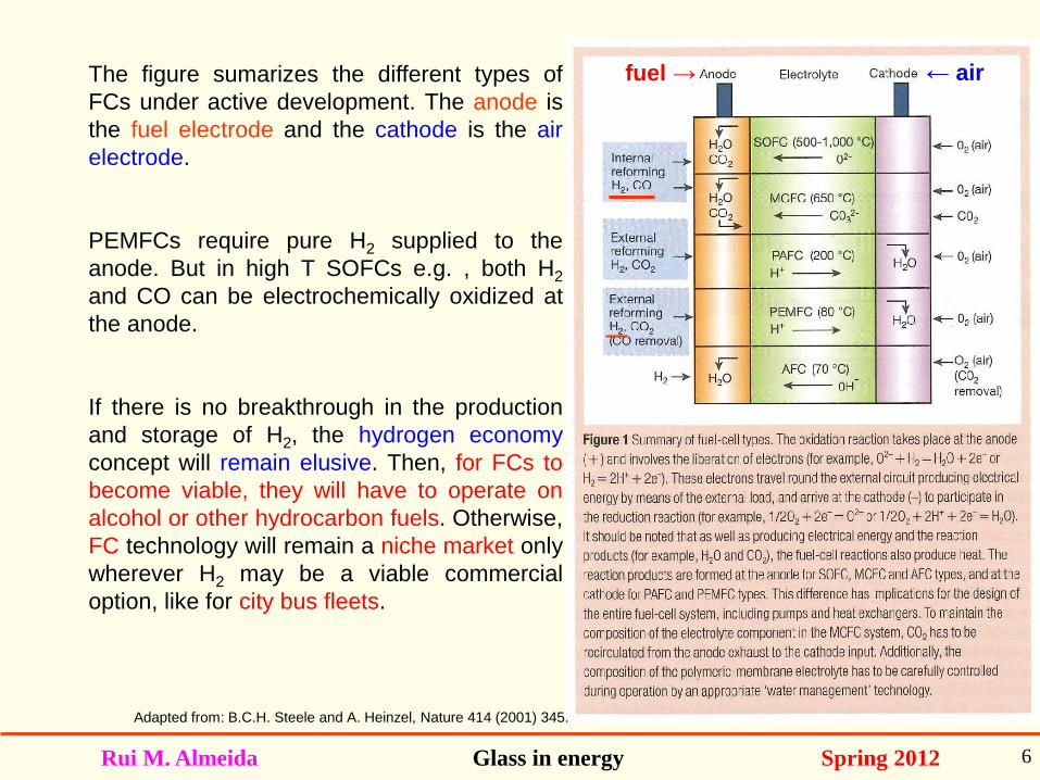
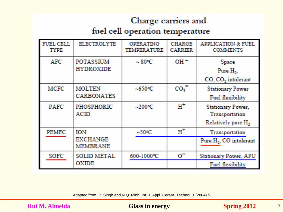
The main constituents of a FC are the electrolyte (ionic conductor) and the two electrodes
(cathode and anode). The two main types of FC where this lecture will focus utilize solid
electrolytes; they are the intermediate/high temperature Solid Oxide Fuel Cells (SOFCs)
and the low temperature Proton Exchange Membrane Fuel Cells (PEMFCs).
At present, only the technologies employing solid electrolytes (SOFC and PEMFC) seem
to have real potential.
SOFCs are all ceramic devices which operate in the range of 500 – 1000 oC. One
advantage over low T cells is their ability to use CO as a fuel. But their cost is high.
The current PEMFCs use ~ 100 micron thick film Nafion membranes and thus are also
known as Polymeric-Electrolyte-Membrane FCs (PEMFCs, as well), but they always
require pure H2 fuel supplied to the anode.
Rui M. Almeida Glass in energy Spring 2012 6
Adapted from: B.C.H. Steele and A. Heinzel, Nature 414 (2001) 345.
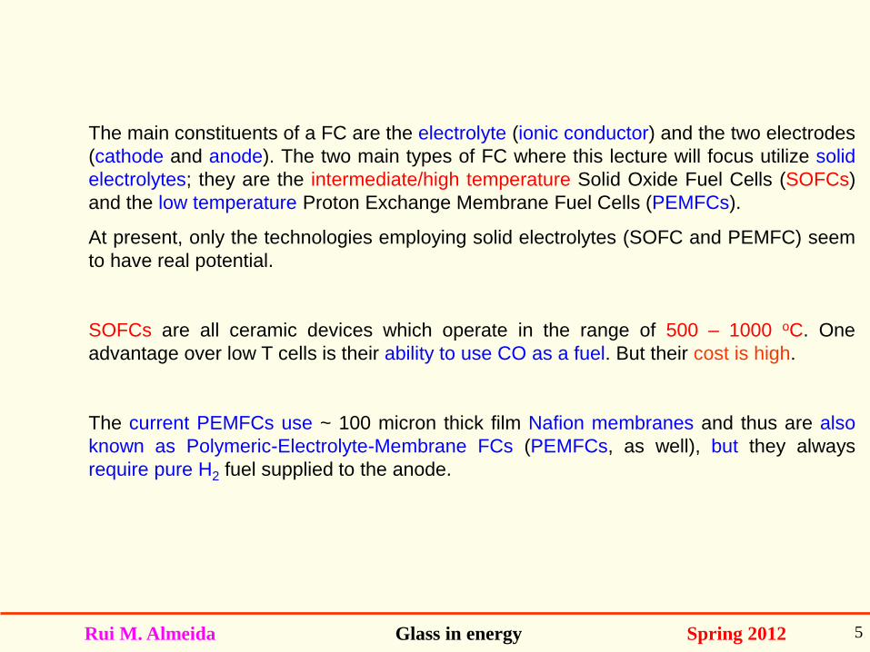
The figure sumarizes the different types of
FCs under active development. The anode is
the fuel electrode and the cathode is the air
electrode.
PEMFCs require pure H2 supplied to the
anode. But in high T SOFCs e.g. , both H2
and CO can be electrochemically oxidized at
the anode.
If there is no breakthrough in the production
and storage of H2, the hydrogen economy
concept will remain elusive. Then, for FCs to
become viable, they will have to operate on
alcohol or other hydrocarbon fuels. Otherwise,
FC technology will remain a niche market only
wherever H2 may be a viable commercial
option, like for city bus fleets.
fuel → ← air
Rui M. Almeida Glass in energy Spring 2012 7
Adapted from: P. Singh and N.Q. Minh, Int. J. Appl. Ceram. Technol. 1 (2004) 5.
Rui M. Almeida Glass in energy Spring 2012 8
Adapted from: http://www.threebond.co.jp/en/technical/technicalnews/pdf/tech60.pdf Q.
Rui M. Almeida Glass in energy Spring 2012 9
Solid Oxide Fuel cells
Rui M. Almeida Glass in energy Spring 2012 10
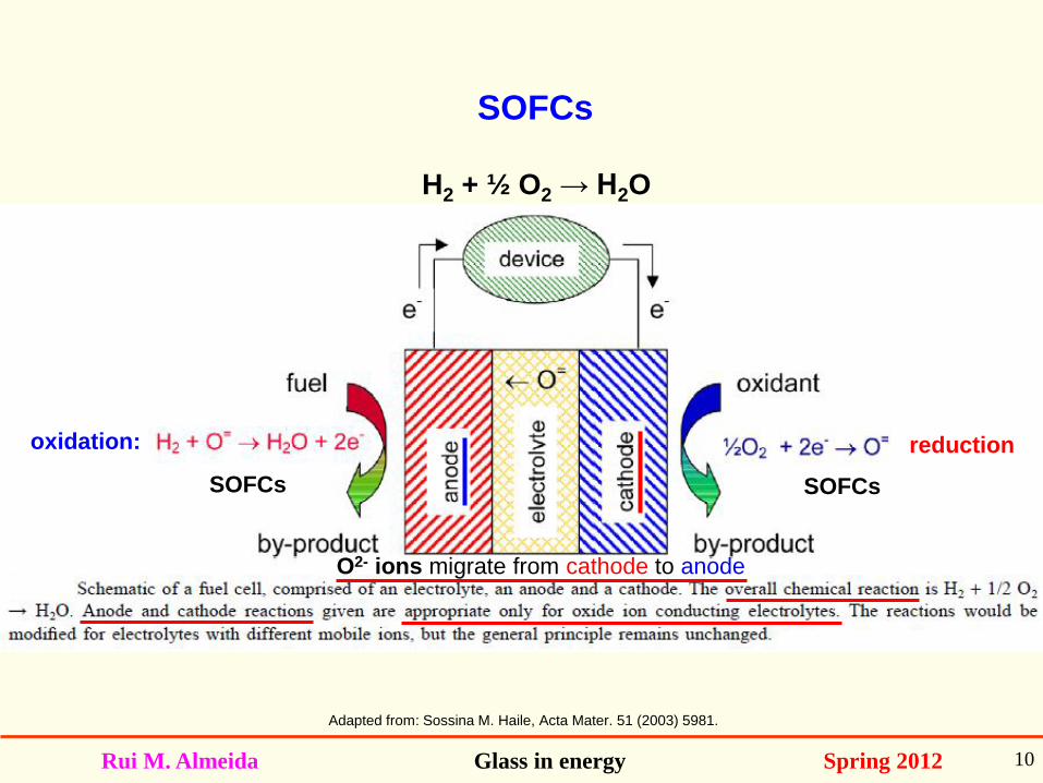
Adapted from: Sossina M. Haile, Acta Mater. 51 (2003) 5981.
SOFCs SOFCs
SOFCs
oxidation: reduction
H2 + ½ O2 → H2O
O2- ions migrate from cathode to anode
Rui M. Almeida Glass in energy Spring 2012 11
Adapted from: Sossina M. Haile, Acta Mater. 51 (2003) 5981.
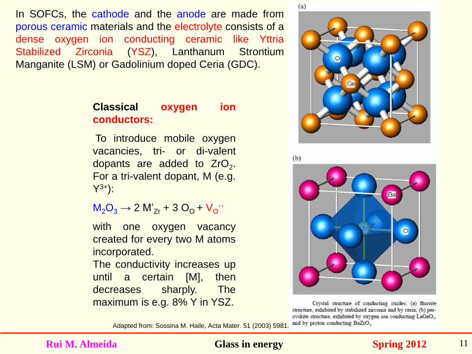
Classical oxygen ion
conductors:
To introduce mobile oxygen
vacancies, tri- or di-valent
dopants are added to ZrO2.
For a tri-valent dopant, M (e.g.
Y3+):
M2O3 → 2 M’Zr + 3 OO + VO..
with one oxygen vacancy
created for every two M atoms
incorporated.
The conductivity increases up
until a certain [M], then
decreases sharply. The
maximum is e.g. 8% Y in YSZ.
In SOFCs, the cathode and the anode are made from
porous ceramic materials and the electrolyte consists of a
dense oxygen ion conducting ceramic like Yttria
Stabilized Zirconia (YSZ), Lanthanum Strontium
Manganite (LSM) or Gadolinium doped Ceria (GDC).
Rui M. Almeida Glass in energy Spring 2012 12
Since oxygen ion conductors require high temperature operation for good conductivity, a
SOFC operates at T ~ 600 - 900 oC: so the key material challenges are related to the
thermo-mechanical and thermo-chemical stabilities of the sealant. In SOFCs, lowering
the operating temperature will lower costs.
The development of a robust, reliable sealing technology is one of the main
technological barriers to the wide-spread commercialization of intermediate temperature
SOFCs. Candidates are glasses and glass-ceramics. Namely GCs based on alkaline
earth silicate and aluminosilicate materials have been investigated, as these have
expansion coefficients ~ 100 - 120 x 10-7 K-1. Another proposal has been to use,
instead of rigid seals, non-crystallizing glass compositions that perform as a “viscous
gasket” under the operational conditions.
Other critical issues for SOFCs are the electrodes, in particular the anode (fuel
electrode). The air electrode (cathode) is a composite of (La,Sr,Mn) oxide (LSM) with
YSZ to allow reduction of O2 molecules to oxide ions transporting electrons to the
cathode/electrolyte interface. The fuel electrode facilitates the oxidation of the fuel and
electron transport from the electrolyte to the fuel/anode interface.
The possible SOFC fuels range from H2 to methane, CO, diesel or coal. But, in fact,
fairly pure H2 is used in most cases.
Solid oxide fuel cells
Rui M. Almeida Glass in energy Spring 2012 13
Large SOFC systems operate at the highest temperatures (HT-SOFCs).
Smaller systems operate at intermediate temperatures (IT-SOFCs), without
compromising the internal resistance of the cell and are planar stacks. These could even
be used to supply power for A/C units in automotive vehicles.
HT operation places rigorous durability requirements on cell components. While HT
operation may be preferred in terms of efficiency, for portable (intermittent) power
applications, lower T is favored (IT-SOFCs).
Rui M. Almeida Glass in energy Spring 2012 14
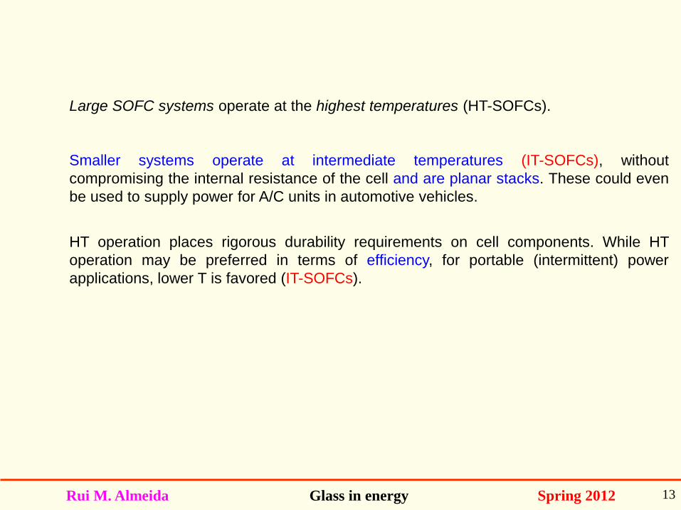
Adapted from: http://www.sigmaaldrich.com/materials-science/material-science-products.html?TablePage=105700873
Schematic of SOFC operating on H2 or CO.
SOFCs may have planar (IT-SOFCs) or tubular (HT-SOFCs) configuration. Seals are
necessary in planar stacks.
Planar SOFCs require seals to isolate anode and cathode chambers in a stacked
configuration. Literature on the sealants is limited, but these are usually glasses or glass
ceramics (GCs). Still, thermal stress-induced failure at glass seals is a serious problem for
planar designs. At present, heating and cooling rates cannot exceed ~ 500 oC/hr, due to
stresses associated with the thermal expansion mismatch and with the brittle glass and
ceramic (GC) seals.
cathode
anode
electrolyte
Rui M. Almeida Glass in energy Spring 2012 15
Adapted from: P. Singh and N.Q. Minh, Int. J. Appl. Ceram. Technol. 1 (2004) 5.
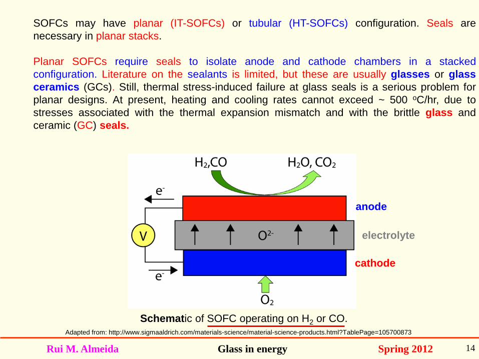
Tubular designs in HT-SOFCs (used e.g. by Siemens-Westinghouse, S-W) elliminate the HT
sealing problem. S-W use a 1.5 m porous tubular cathode of LSM. Electrochemical vapor
deposition (EVD) is used to deposit a dense thick film (30 – 40 µm) of YSZ electrolyte. The
anode is porous Ni-YSZ. The S-W tubular design remains the most developed SOFC. Such
large systems ~ 70% efficiencies operating at the highest temperatures.
Tubular designs are free of seals, but are very costly, namely due to use of EVD. So nowadays
one is trying to reduce the operation temperature to 500 – 600 oC only (IT-SOFCs).
Rui M. Almeida Glass in energy Spring 2012 16
Adapted from: http://www.sciencedaily.com/releases/2009/05/090521184437.htm
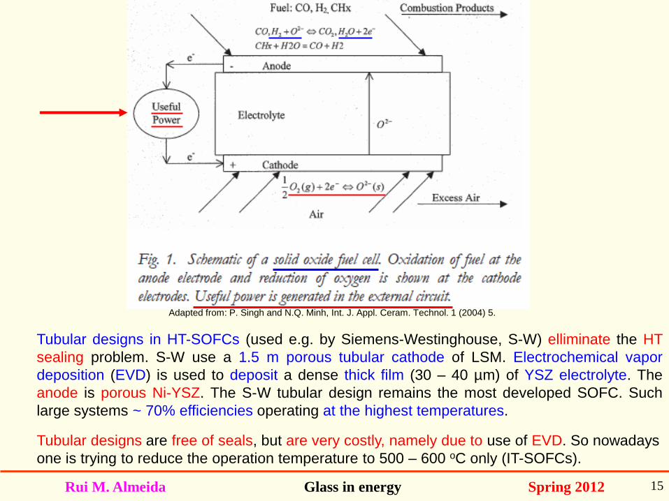
The seal problem is the biggest problem for commercialization of IT-SOFCs.
(cathode)
(anode)
Interconnects separate
fuel and air and provide
cell-to-cell connection in
a planar stack.
Single cell
(repeating unit)
Glass seal
seals isolate anode and cathode
Planar IT-SOFC
Glass seal
Rui M. Almeida Glass in energy Spring 2012 17
Adapted from: Paul A. Lessing, J. Mater. Sci. 42 (2007) 3465.
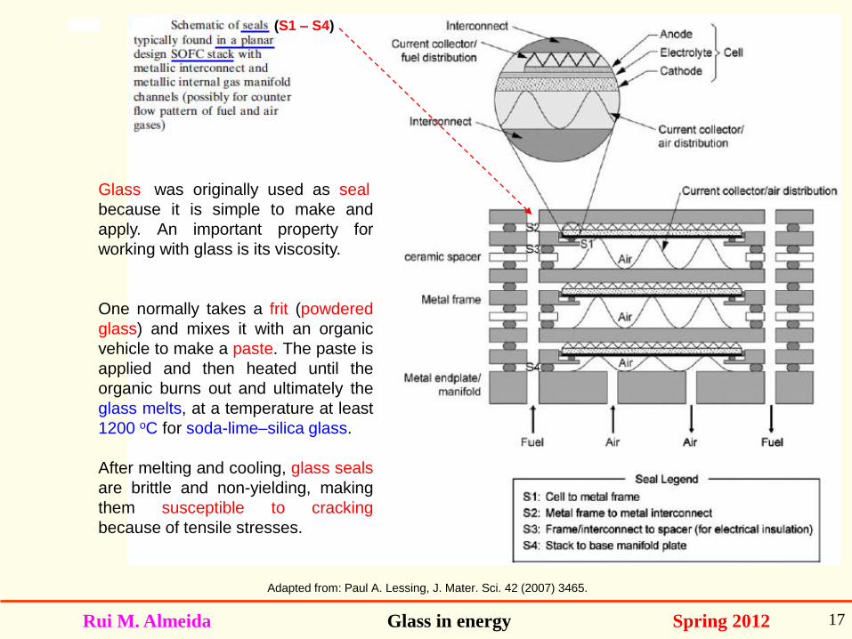
Glass was originally used as seal
because it is simple to make and
apply. An important property for
working with glass is its viscosity.
One normally takes a frit (powdered
glass) and mixes it with an organic
vehicle to make a paste. The paste is
applied and then heated until the
organic burns out and ultimately the
glass melts, at a temperature at least
1200 oC for soda-lime–silica glass.
After melting and cooling, glass seals
are brittle and non-yielding, making
them susceptible to cracking
because of tensile stresses.
(S1 – S4)
Rui M. Almeida Glass in energy Spring 2012 18
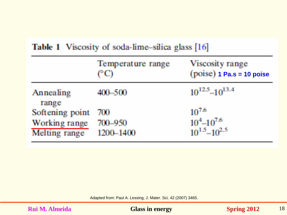
Adapted from: Paul A. Lessing, J. Mater. Sci. 42 (2007) 3465.
1 Pa.s = 10 poise
Rui M. Almeida Glass in energy Spring 2012 19
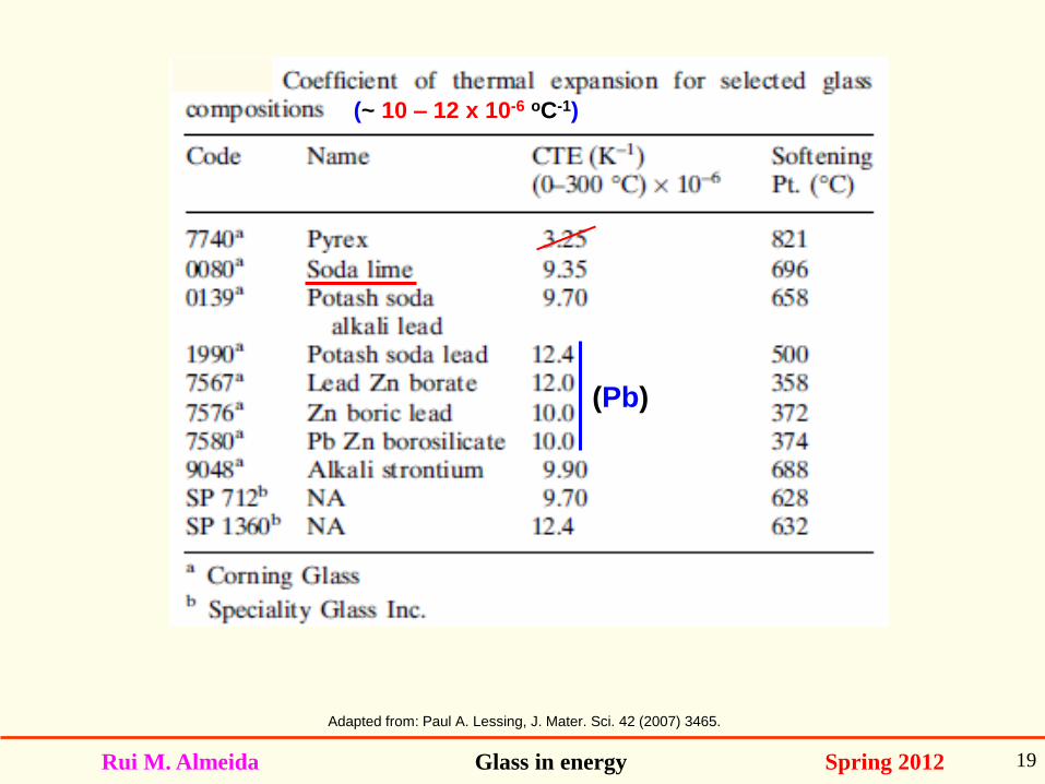
Adapted from: Paul A. Lessing, J. Mater. Sci. 42 (2007) 3465.
(~ 10 – 12 x 10-6 oC-1)
(Pb)
Rui M. Almeida Glass in energy Spring 2012 20
Adapted from: Paul A. Lessing, J. Mater. Sci. 42 (2007) 3465. Q.
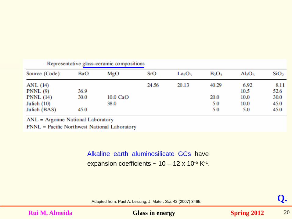
Alkaline earth aluminosilicate GCs have
expansion coefficients ~ 10 – 12 x 10-6 K-1.
Rui M. Almeida Glass in energy Spring 2012 21
PEM Fuel cells
Rui M. Almeida Glass in energy Spring 2012 22
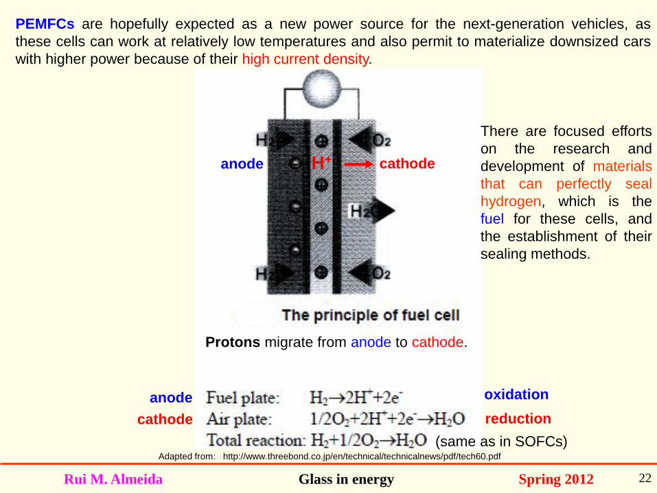
Adapted from: http://www.threebond.co.jp/en/technical/technicalnews/pdf/tech60.pdf
anode
cathode
oxidation
reduction
PEMFCs are hopefully expected as a new power source for the next-generation vehicles, as
these cells can work at relatively low temperatures and also permit to materialize downsized cars
with higher power because of their high current density.
There are focused efforts
on the research and
development of materials
that can perfectly seal
hydrogen, which is the
fuel for these cells, and
the establishment of their
sealing methods.
Protons migrate from anode to cathode.
anode cathode H+
(same as in SOFCs)
Rui M. Almeida Glass in energy Spring 2012 23
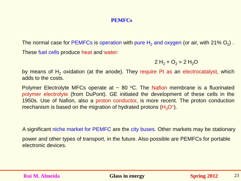
The normal case for PEMFCs is operation with pure H2 and oxygen (or air, with 21% O2) .
These fuel cells produce heat and water:
2 H2 + O2 = 2 H2O
by means of H2 oxidation (at the anode). They require Pt as an electrocatalyst, which
adds to the costs.
Polymer Electrolyte MFCs operate at ~ 80 oC. The Nafion membrane is a fluorinated
polymer electrolyte (from DuPont). GE initiated the development of these cells in the
1950s. Use of Nafion, also a proton conductor, is more recent. The proton conduction
mechanism is based on the migration of hydrated protons (H3O+).
PEMFCs
A significant niche market for PEMFC are the city buses. Other markets may be stationary
power and other types of transport, in the future. Also possible are PEMFCs for portable
electronic devices.
Rui M. Almeida Glass in energy Spring 2012 24
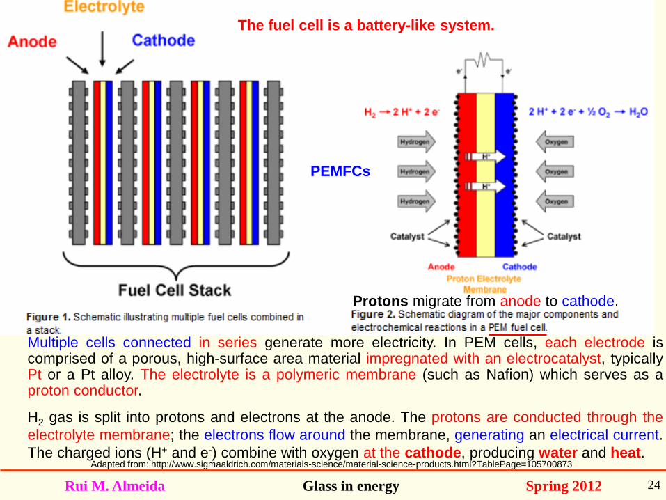
Multiple cells connected in series generate more electricity. In PEM cells, each electrode is comprised of a porous, high-surface area material impregnated with an electrocatalyst, typically Pt or a Pt alloy. The electrolyte is a polymeric membrane (such as Nafion) which serves as a proton conductor.
H2 gas is split into protons and electrons at the anode. The protons are conducted through the
electrolyte membrane; the electrons flow around the membrane, generating an electrical current.
The charged ions (H+ and e-) combine with oxygen at the cathode, producing water and heat.
The fuel cell is a battery-like system.
PEMFCs
Adapted from: http://www.sigmaaldrich.com/materials-science/material-science-products.html?TablePage=105700873
Protons migrate from anode to cathode.
Rui M. Almeida Glass in energy Spring 2012 25
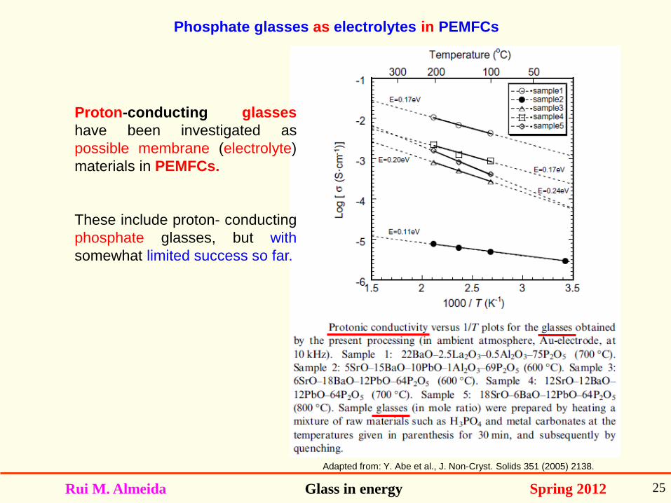
Adapted from: Y. Abe et al., J. Non-Cryst. Solids 351 (2005) 2138.
Phosphate glasses as electrolytes in PEMFCs
Proton-conducting glasses
have been investigated as
possible membrane (electrolyte)
materials in PEMFCs.
These include proton- conducting
phosphate glasses, but with
somewhat limited success so far.
Rui M. Almeida Glass in energy Spring 2012 26
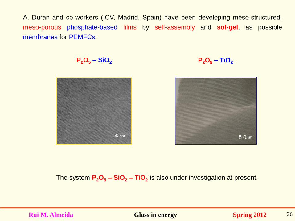
A. Duran and co-workers (ICV, Madrid, Spain) have been developing meso-structured,
meso-porous phosphate-based films by self-assembly and sol-gel, as possible
membranes for PEMFCs:
50 nm
P2O5 – SiO2 P2O5 – TiO2
5 0nm
The system P2O5 – SiO2 – TiO2 is also under investigation at present.
Rui M. Almeida Glass in energy Spring 2012 27
In summary, glasses may be used for PEMFCs, as proton conducting membranes
(electrolytes); in intermediate temperature SOFCs, glasses and glass-ceramics are used
as sealants.
The main trend at present are PEM (polymer) FCs for transportation and HT-SOFCs for
large stationary applications.
However, PEMFCs must still reduce costs with Pt catalysts. In HT-SOFCs, the main
barrier is the anode; the best so far is Ni-YSZ, but it still has corrosion resistance
problems.
Q.
Rui M. Almeida Glass in energy Spring 2012 28
Hydrogen storage
Rui M. Almeida Glass in energy Spring 2012 29
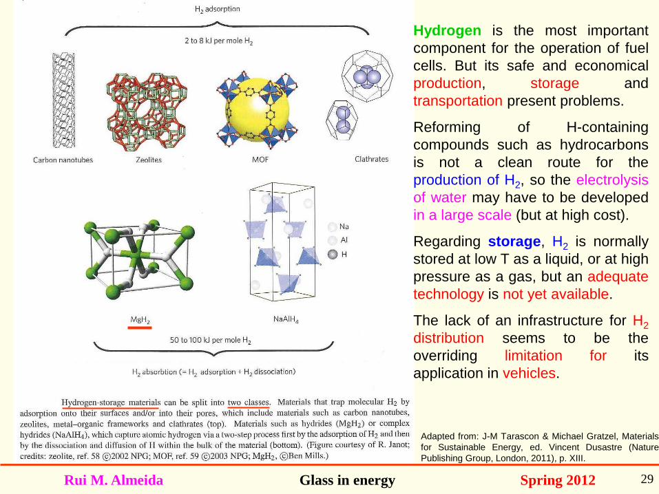
Adapted from: J-M Tarascon & Michael Gratzel, Materials
for Sustainable Energy, ed. Vincent Dusastre (Nature
Publishing Group, London, 2011), p. XIII.
Hydrogen is the most important
component for the operation of fuel
cells. But its safe and economical
production, storage and
transportation present problems.
Reforming of H-containing
compounds such as hydrocarbons
is not a clean route for the
production of H2, so the electrolysis
of water may have to be developed
in a large scale (but at high cost).
Regarding storage, H2 is normally
stored at low T as a liquid, or at high
pressure as a gas, but an adequate
technology is not yet available.
The lack of an infrastructure for H2
distribution seems to be the
overriding limitation for its
application in vehicles.
Rui M. Almeida Glass in energy Spring 2012 30
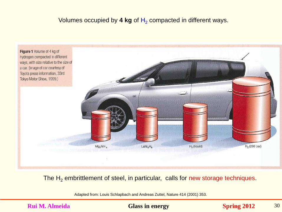
Volumes occupied by 4 kg of H2 compacted in different ways.
Adapted from: Louis Schlapbach and Andreas Zuttel, Nature 414 (2001) 353.
The H2 embrittlement of steel, in particular, calls for new storage techniques.
Rui M. Almeida Glass in energy Spring 2012 31
Glass microspheres for hydrogen storage
The use of Hollow Glass Micro Spheres (HGMS) was proposed ~ 15 years ago as a
viable alternative for H2 storage and transportation at pressures up to 100 MPa
(~ 1000 atm).
Recycled cullet can be used to prepare such spheres and, if one of them breaks, the
volume of H2 released is too small to cause any hazard. Sphere size is ~ 50 – 100 µm.
The HGMS can be fabricated by flame spray pyrolysis of glass frit. Glass frit is
dropped directly into an oxy-fuel flame, with the glass viscosity becoming low enough
for the frit particles to take on a spherical shape (as a result of surface tension), which
is retained during quick cooling. The hollow cavity formation inside the spheres is
obtained by adding a blowing agent to the glass frit (e.g. Na2SO4, used as a refining
agent in common glass melting), which decomposes and expands.
The H2 loading of the spheres is achieved by placing them in a high pressure hydrogen
atmosphere and heating them up to a temperature sufficient for H2 in-diffusion.
Outgassing is later forced through re-heating.
Rui M. Almeida Glass in energy Spring 2012 32
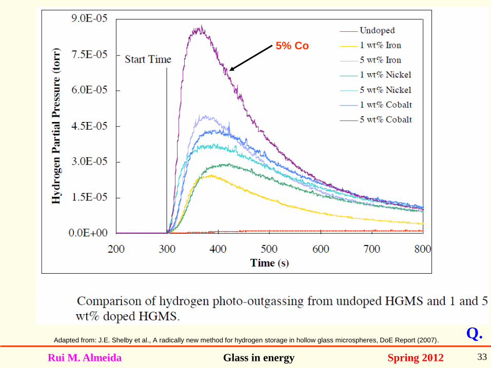
Glass microspheres for hydrogen storage
Recently, Shelby and co-workers have suggested the occurrence of photo-induced
outgassing of H2 from the HGMS, when these are doped with elements such as Fe, Co
or Ni and are exposed to near-IR light (~ 2 µm), diffusion is greatly enhanced when
compared with heating alone. The rate of H2 release can be controlled by the light
intensity and it also increases slightly with an increase in microsphere diameter.
Rui M. Almeida Glass in energy Spring 2012 33
Adapted from: J.E. Shelby et al., A radically new method for hydrogen storage in hollow glass microspheres, DoE Report (2007). Q.
5% Co
Rui M. Almeida Glass in energy Spring 2012 34
References:
- Richard K. Brow and Melodie L. Schmitt, J. Eur. Cer. Soc. 29 (2009) 1193.
- A. Atkinson et al., Nature Mater. 3 (2004) 17.
- B.C.H. Steele and A. Heinzel, Nature 414 (2001) 345.
- Sossina M. Haile, Acta Mater. 51 (2003) 5981.
- J.E. Shelby et al., A radically new method for hydrogen storage in hollow glass microspheres,
DoE Report (2007).