globa l se is m ogr a phic n e twor k d a ta logge r spe c ... · s ens itivity t he sensitivity of...
TRANSCRIPT
November 20, 20031
Global Seismographic Network Data Logger Specifications
(Prepared by the IRIS Instrumentation Committee)
Charge to the Committee
The charge to the Instrumentation Committee was to review and comment on the designgoals and to help the GSN Committee formulate specifications based on these goalswhich can be used in a “request for quotation” that can be sent to selected manufacturersof digital data loggers for the purpose of prototype “next generation” GSN data logger(s).
Review of Suggested Technical Specifications from GSN Committee
Appendix A contains technical specifications suggested by the GSN Committee.
Seismological requirements guiding Technical Specifications
Provide high fidelity digital recordings of all teleseismic ground motions (adequate toresolve at or near ambient noise up to the largest teleseismic signals over
the bandwidth from free oscillations (10-4 Hz) to teleseismic body waves(up to approximately 15 Hz)).
Bandwidth to record regional earthquake waves at all stations (up to about 15 Hz orhigher, as warranted by regional wave propagation considerations).
To model amplitudes to 20%, the aggregate sources of amplitude error (gain stability,cross axis coupling, and cross talk) should be less than 2% and individualcontributions should be less than that.
On-scale broadband recordings of earthquakes as large as Mw = 9.5 (equivalent to the1960 Chile earthquake) at 30 degrees. On-scale low-gain recordings of allearthquakes at 1 sample/sec.
Noise below ambient earth noise.
Timing adequate to measure teleseismic body wave arrivals to 0.01 s.
Clip level of 5.8 mm/s rms over the band 10-4 (or below) to 15 Hz, while resolving theUSGS low-noise model.
Resolution of 3 dB below the NLNM is sufficient, but not necessary at all sites (or at any

November 20, 20032
site at all frequencies).
Other requirements guiding Technical Specifications
Provide real-time or near real-time data telemetry (to support event monitoring, providedata for scientific analysis in a timely manner, and improve maintenanceresponse time).
Equipment must be isolated from environmental problems including corrosion, waterdamage, dust, radio frequency interference, electrical surges, atmosphericpressure changes, and to some extent temperature changes. The equipmentshould be highly reliable.
On-site data storage must be provided for telemetered sites and removable non-volatilestorage must be provided for non-telemetered sites.
Equipment must be robust, sustaining high up-time performance.
For the purposes of the Instrumentation Committee report, it is assumed that three typesof sensors are used (Appendix C):
1. STS1 or KS54000 with a flat response to velocity from 0.0027 Hz (360 s) to 5 Hzsampled at 0.1, 1, 20 samples/s.
2. STS2 or CMG3T with a flat response to velocity from 0.0083 Hz (120 s) to 40 Hzsampled at 1, 40 samples/s.
3. Episensor or FBA-23 with a flat response to acceleration from DC to 50 Hzsampled at 1, 100 samples/s.
It is noted that no single sensor–digitizer combination can cover all the frequency bandsof interest with the desired dynamic range.
GSN Datalogger Specification Recommended by Instrumentation Committee
Clip Level ±20V peak-to-peak differential analog input
Sensitivity The sensitivity of each digitizer channel (counts per volt)shall be accurate to 0.1% or better at DC (0 Hz).
Amplification Configurable gains of 0 dB and 30 dB
Noise Level Resolution of 3 dB below the NLNM is sufficient, but not
November 20, 20033
necessary at all sites (or at any site at all frequencies).
Linearity -110 dB or better, to be measured as follows: Use a LowDistortion Oscillator (LDO) known to be linear to betterthan -120 dB to input a signal consisting of 1.00 + 1.02 Hzinto the digitizer running at 20 sample per second. Eachsignal (before summing) should have a peak-to-peakamplitude of 10 volts, so that the sum of the two signals hasa maximum peak-to-peak amplitude of 20 volts (i.e, 50% ofmaximum full-scale digitizer input). Perform a spectralanalysis on the digitized signal from this test. The averagespectral value from 0.0003 Hz to 0.25 Hz should be at least110 dB less than the peak spectral values at 1.00 and 1.02Hz. The average spectral value from 1.5 Hz to 10 Hzshould be also be at least 110 dB down from the peaks near1 Hz.
Timing External time reference accurate to 1 ms absolute and a freerunning oscillator with a maximum temperature sensitivityof 0.1 ppm/degree C and a maximum drift rate (at constanttemperature) of 0.1 ppm.
Sample timing Data samples on all channels running at the same samplerate shall be taken simultaneously to within 1% of thesample interval.
Sample Rates Capable of sampling continuous 3-component data fromthe VBB sensor at 0.1, 1, 20, and 40 samples per second.Capable of sampling continuous or event-triggered 3-component data from BB, SP, or strong motion sensors at1, 20, 40, or 100 samples per second. Optional samplerates at 200 samples per second and greater will be viewedfavorably. Capable of providing multiple simultaneoussample rates from all broadband and strong motion sensors.
Compression Capable of data compression at all sample rates. Packetswill have a maximum length of 1200 samples /channel toprovide adequate latency.
November 20, 20034
Telemetry Capability Data telemetry must be error corrected, must supportstandard IP communications protocol(s), must support avariety of communications technologies, and must becapable of transmitting back logged and triggered datawithout interrupting real-time data delivery. Must supporta command and control capability.
Connectivity Provide for secure communication.
Temperature Range Operational range of 0°C to +30°C, storage range –20°C to+60°C. An operational range of –20°C to +50°C will beviewed favorably. Maximum 1% change in self-noise andsensitivity (counts/volt) over operational range.
Control Functions For each set of 3 high resolution channels, there shall bethree control functions, each of which shall be separatelyprogrammable to be TTL active high or active low. Thiswill allow sensor controls such as mass lock/unlock, masscenter, and calibration enable.
Calibrator Capable of generating step, sine, and random telegraphcalibration signals configurable to provide sensor outputsbetween 5% and 50% of full scale. It shall be possible toschedule calibration sequences. Calibration signals shall beaccompanied by calibration-enable signals for theappropriate set of 3 sensor channels (see also “ControlFunctions”).
Calibrations Good to 1% and gain stability of 1% between calibrations.
EMI-RFI Instrument output shall be unaffected by reasonablechanges in magnetic field and reasonable levels of radiofrequency interference (see Appendix B).
November 20, 20035
Reliability Instrument shall be designed for a 10-year (minimum) lifeand shall be shown to have a calculated 40,000 hour(minimum) mean time to failures, according to theprocedures specified in Appendix B.
Maintenance System must be manufactured such that individual modulescan be replaced in the field or lab, not just at the factory.Adequate documentation for field maintenance must besupplied.
Size Vendors are encouraged but not required to providesolutions for 6.5” ID borehole
Authentication Vendors are encouraged but not required to propose pathfor future upgradeability for IMS authentication
Storage Format Permanent storage must use lossless compression andeither provide miniseed or software to convert to miniseed
Configuration Configuration information stored in each datalogger shouldallow reconstruction of the complete datalogger transferfunction for all active datastreams. Configurationinformation should include:
• Manufacturer name
• Datalogger type
• Datalogger serial number
• Board serial numbers and version numbers
• Factory calibration parameters including:
• Nominal poles and zeros response if applicable
• FIR filter coefficients
• A/D conversion factors for each channel
Connectors The function of all external connectors shall be clearly
November 20, 20036
labelled. Connectors shall be reliable over the entire rangeof environmental conditions likely to be experienced in atypical seismic vault or cave.
High-resolution channels Standard set of 9 channels, with the capability of adding orsubtracting 3 channels at a time in modular fashion.Resolution will be at least 22 bits from 0.001 Hz to 15 Hzand at least 21 bits from 15 Hz to 100 Hz (see AppendixB). Ultra-high resolution of more than 22 bits atfrequencies greater than 1 Hz on at least 3 channels will beviewed favorably.
Cross-talk maximum < -135 dB
Auxiliary analog channels minimum 16 channels at 16 bit max sample rate 1 sps.
Indicators Shall include easily-interpreted visual indicators for powerstatus, data acquisition status, communication link activity,storage archive access, and clock status/quality.
Control parameters System shall have the capability to allow the user to set allparameters necessary for full and robust control of thesystem, including sample rates, recording modes, sensorcontrol signals (specified separately under “ControlFunctions”), etc. Provision of an industry standardoperating system and open source code will be viewedfavorably.
SOH monitoring Capable of providing state-of-health (SOH) monitoring.SOH parameters include the following as a minimum:mass position, internal temperature and voltages, externalpower sources, external power source history, and batteryvoltages. SOH parameters shall be available in continuoustelemetry packets for ease of monitoring SOH withoutspecial requests.
Anti-alias filtering All channels shall be derived using linear phase “brick-wall” filters with high frequency corner fc at least 80% ofthe Nyquist frequency and stop band amplitude (Nyquist tohigher frequencies) at least 95 dB below the pass band.Pass band (DC to fc) ripple shall be less than 5%.
November 20, 20037
Power Consumption Datalogger system shall consume 1 watt or less per high-resolution channel. (Ultra high-resolution channels are thesame as high-resolution channels for this purpose.)
Power Supply Voltage 10 V to 30 V
Vibration and Shock Must survive commercial shipping.
Data Storage, Optional Separated Data Acquisition and Archive/Monitoring Capability
! It shall be possible to physically separate the dataacquisition/time tagging function (DA function) from anarchive/monitoring function (A/M function). The twofunctions shall be capable of communicating via eitherserial link or an IP link (such as TCP/IP, UDP, etc).
! The DA equipment that provides the data acquisition/timetagging function shall have a highly reliable deep archivestorage capability with no moving parts, and shall have acapacity of at least 1 Gbyte, with the option to expand thecapacity as necessary to be able to store up to one year ofdata. It shall be possible to physically remove the deeparchive storage module for mailing to a data center withoutshutting down the data acquisition function or power (i.e.“hot swappable”). It shall also be possible to download thedata from the deep archive to a portable storage device (e.g.laptop computer) via a data port.
! The A/M equipment that provides the separable archive andmonitoring function shall have the capability of archivingall data from the DA function via a serial or IP telemetrylink. (Note that the A/M equipment may be co-locatedwith, or separated from, the DA equipment.) The A/Mequipment shall also have the capability of archiving dataon an easily removable, hot-swappable, smaller-capacitymedium capable of storing 2 to 8 weeks of data (capacityoptional). This smaller storage medium shall be mailablethrough normal postal or express mail services (may be CDor flash memory card, for example).

November 20, 20038
! The A/M function shall provide full capability forcontrolling and monitoring the status of the DA function.
Evaluation of Competing Systems
RFP must be written with testable specs (see Appendix B)
Digitizer resolution computed according to the Modified Noise Power Ratio test.
Manufacturers shall provide their own test results evaluated at a standard test facilitysuch as Sandia National Labs.
Pre-productions or prototype units provided during evaluation phase of contract will befully tested.
Production units must also comply with specs and will be spot checked at random toassure compliance (using a subset of acceptance tests).
Cost, technical performance, and manufacturers prior performance on similar contractswill be considered for evaluation.
Data Format
At a minimum, data packets (both seismic and SOH) generated by the DAS shall includeinformation that:
• Uniquely identifies the station and channel
• Provides information needed to decode and use the data including:
o Data type and format
o Packet length
o Record number
o Time correction
In addition, the DAS shall be capable of formatting the manufacturer, equipment type,serial number, and metadata (e.g., response information) for the DAS and collocatedsensors and power equipment for occasional transmission. The goal is to make fieldequipment as self documented as possible.
Appendix B– Instrumentation Testing
The following provides details of standards and is based on Appendix C from the USGS
November 20, 20039
Open-File Report 02-92, “Technical Guidelines for the Implementation of The AdvancedNational Seismic System—Version 1.0”, Prepared by the ANSS Technical IntegrationCommittee.
Resolution
The resolution of digitizers is to be computed according to the Modified Noise PowerRatio test as described in Sandia National Laboratories technical report SAND 94-0221,“Modified Noise Power Ratio Testing of High Resolution Digitizers”, by T. S.McDonald, 1994. The test involves driving two identical digitizer channels with pseudorandom, band limited, Gaussian noise and measuring the noise power ratio (NPR),defined as the ratio of the RMS input noise to the RMS non-coherent noise floor (bothaveraged over the digitizer pass band). The resolution is estimated indirectly bycomparing the NPR as a function of RMS input noise against ideal digitizers. Copies ofSAND 94-0221 will be provided by the IRIS.
Vendors are required to provide a plot of NPR in decibels versus loading factor indecibels compared with theoretical curves for ideal digitizers of varying dynamic ranges(i.e., number of bits). The loading factor is the ratio of the digitizer clip level to the RMSinput noise. The NPR must be determined at RMS input levels between the RMS shortedinput and clipping in 10 dB steps. Vendors are also required to provide a plot of shortedinput power in decibels versus frequency and at least one plot of the phase of the non-coherent noise in degrees versus frequency. Both plots must including at least thefrequency band 0 < f < 50 Hz.
Magnetic Fields
When equipment is operated in the presence of magnetic field intensity changes of up to10 milligauss, there shall be no detectable effect in the output signal.
Atmospheric Pressure
Sensitivity to atmospheric pressure changes shall not be detectable at the output of theinstrument including changes due to passing fronts and thunderstorms.
Radio Frequency Interference (RFI)
When equipment is operated in the presence of RFI there shall be no detectable effect inthe output signal provided that the RFI does not exceed FCC standards. For relevantstandards see “Limits for General Population/Uncontrolled Exposure” (FCC document“A Local Government Official’s Guide to Transmitting Antenna RF Emission Safety:Rules, Procedures, and Practical Guidance”, June 2, 2000).
November 20, 200310
Mean Time Between Failures (MBTF)
MTBF shall be estimated by the Bell Communications Research (Belcore) method. Themethod is defined in “Reliability Prediction Procedure for Electronic Equipment”(Belcore document number TR-332, Issue 6) and may be computed using commerciallyavailable software (e.g., RelCalc).
Configuration Information
DASes shall be capable of receiving manufacturer, model, serial numbers, and otherrelevant information as specified (e.g., nominal response information for sensors andpower status information for power systems). Data shall be communicated in the ASCIIcharacter code via a 1-wire network (MicroLAN) as described in http://www.maxim-ic.com/1st_pages/tb1.htm.
Temporary Shallow Submersion in Water
The International Electrotechnical Commission (IEC) standard 60529 specifies degreesof protection provided by enclosures, also known as the IP code. IRIS requires IP67level protection, which means 1) the enclosure shall be dust tight and 2) the ingress ofwater shall not be sufficient to damage the electronics when submerged under 1 m ofwater (measured from the base) for 30 minutes.

FINAL VERSION –GSN Design Goals Subcommittee ReportReviewed by GSN Standing Committee October, 2002
1
Global Seismic NetworkDesign Goals Update 2002
August 26, 2002
GSN ad hoc Design Goals Subcommittee
Thorne Lay, ChairJon BergerRay BulandRhett ButlerGoran EkstromBob HuttBarbara Romanowicz
Appendix A
FINAL VERSION –GSN Design Goals Subcommittee ReportReviewed by GSN Standing Committee October, 2002
2
Introduction
The GSN Design Goals Subcommittee (DGS) agreed that the appropriate approach was for us tocouch this effort in terms of an update of relevant portions of the 1985 document "The DesignGoals for a New Global Seismographic Network" prepared by the SCGSN Instrumentation andData Collection Subcommittees. That document was redistributed, and studied by the DGS. Ourfocus is directed at updating the GSN design goals to provide input to the InstrumentationCommittee, which will then be tasked to develop technical specifications. Design goals are framedby the context of both scientific goals of the research community and by general philosophy ofnetwork design and recording system attributes that service the scientific applications of the data.
From the perspective of today's GSN, major elements of the 1985 Design Goals document havebeen implemented in several respects. That document emphasized 20 sample/sec broadband digitalrecording with real-time or near real-time data telemetry of all teleseismic ground motions(assuming about 20 degrees station spacing) for earthquakes as large as Mw = 9.5 (equivalent to the1960 Chile earthquake) by a uniform global network of about 100 stations, with low noiseinstrumentation and environment, standardization of system modules, and linearity of response.The intent was for total system noise to be less than the ambient ground noise over the operatingbandwidth.
Some provision was made for the possibility of additional short-period data channels to record localsignals or high frequency teleseismic signals, as well as for low-gain channels, possibly withadditional sensors, to record the largest accelerations experienced by the stations. Over the ensuing17 years, the GSN has achieved significant global coverage (large gaps persist within oceanicregions and continental coverage is non-uniform), and high dynamic range, broadbandinstrumentation has been deployed at all formal GSN stations. Short-period recording has extendedbeyond the general statements of the 1985 document to encompass 40 sample/sec continuousrecording at most stations, along with 80 to 125 sample/sec triggered recording, with short-periodsensors supplementing the basic broadband instrumentation. Strong ground motion instrumentationand triggered channels have been added to stations in earthquake prone areas, and low-gain 1sample/sec channels are continuously recorded.
Limitations
The driving motivation for the GSN has been to record with full fidelity and bandwidth all seismicsignals above the Earth noise, accompanied by some efforts to reduce Earth noise by deploymentstrategies. The primary limitations at many GSN stations at this time are site noise related. Despiteextensive effort, political and logistical situations have resulted in some GSN stations being locatedin noisy environments. The 1985 Design Goal framework does not address the reality ofcompromised site selection. The most useful stations are those that provide abundant high signal-to-noise ratio data, but there is always some trade-off with geographic coverage. While the goalshould be to have low noise sites in general, there will be compromises. Site selection and siteconstruction should be such that there is reasonable assurance of substantial data return, with thegoal being to maximize the bandwidth and useful dynamic range of the GSN signals.
FINAL VERSION –GSN Design Goals Subcommittee ReportReviewed by GSN Standing Committee October, 2002
3
In particular, many stations with useful vertical component signals have horizontal components thatare much lower in quality. Further development of strategies for improved horizontal componentstability and noise reduction is recommended. Discussion of procedures for installation involvingshielding of sensors from temperature and pressure variations should be undertaken to definepractices that optimize horizontal component stability in vaults and boreholes.
A significant concern is that as new station deployment has given way to long-term operations andmaintenance of the network, we find that there are significant non-uniformities in theinstrumentation comprising the GSN today, largely as a result of the historical evolution of thenetwork. This seriously complicates maintenance of the network. As GSN renews and expands itsinstrumentation, efforts toward network-wide standardization of instrument performance, if notinstrumentation, should be a priority, even as flexibility is retained due to variable site attributes.The extent to which compromises in individual station performance are tolerated must be weighedagainst the scientific gains to be had and the increased complexity of network O&M.
Future Directions
So, is sustaining the status quo the recommendation of the DGS? There are actually several majorconcerns that warrant a re-articulation of the design goals for the network and a vigorous effort todevelop next generation instrumentation for the GSN.
Adaptation of GSN design goals to accommodate emerging scientific directions has been, andshould continue to be, an ongoing process. However, since 1984 there has not been a community-wide discussion of scientific directions to guide or modify a future vision of GSN instrumentation.Renewal proposals for IRIS funding from NSF have included updated applications of GSN data,but there has not been a forum for broad thinking on expanded roles or capabilities for GSN in thefuture. Thus, the present work of DGS is framed by a general sense that, at a minimum, theexisting instrumentation strategy is serving the community rather well and the original designcriteria need to be sustained.
Two sorts of network enhancements have been considered: enhancements improving networkperformance, maintainability, and flexibility within existing design goals and enhancementsexpanding the scope of the GSN design goals. The most obvious enhancement of maintainability isto select new instrumentation to replace aging and/or obsolete equipment currently in the field. Themost obvious enhancement to performance and flexibility would be to seek equipment that can beoperated under a wider variety of site conditions. Lower power equipment, in particular, wouldmake many potentially lower noise sites viable as well as reducing power related maintenanceproblems.
For stations that are intrinsically excessively noisy (to the point where the advantage of geographicsiting is outweighed by the paucity of useful signal recovered) it may prove viable to pursue noisesuppression strategies. For example, if auxiliary channels for pressure, temperature and tilting needto be recorded to suppress noise on the horizontals, this should be pursued. Alternatively, mini-arrays may prove useful for signal enhancement in specific pass bands. The potentialimprovements in signal recovery using array deployments for GSN island stations and possibly for
FINAL VERSION –GSN Design Goals Subcommittee ReportReviewed by GSN Standing Committee October, 2002
4
ocean bottom stations warrant detailed consideration in the context of specific scientificapplications.
In addition, enhancements of the GSN may be intrinsically desirable. In particular, the explorationof geophysical platform concepts, modified station density design (e.g., the fixed NSN/GSNnetwork accompanying USArray), and improved ocean environment coverage are all obviouscandidates. Further, there is increasing scientific interest in ultra-long period signals, such as theEarth's spectrum of continuously excited modes and tides. For example, super conductinggravimeters have demonstrated superior response to existing GSN instrumentation for very long-period free oscillations, and inclusion of a subset of these gravimeters at very quiet sits in the GSNmay prove very attractive in the future. The value of high fidelity recording throughout the tidalband is not self-evident, and community discussion of the role GSN should play in data collectionat frequencies below the normal mode band (as for some ocean oscillations) should be undertaken.
Overall Criteria for the GSN
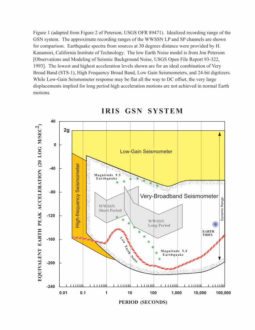
The current characterization of optimal GSN instrumentation capabilities is shown in the attachedFigure 1. A combination of sensors is utilized to realize this full response, and if advances insensor design can achieve greater performance (while retaining linearity, resolution, bandwidth anddynamic range) over the full seismic spectrum it would be attractive to incorporate suchinstrumentation into the GSN in the future. Definition of scientific enterprises that 'push' themargins of the GSN capabilities, such as in the very long period range, the very high frequencyrange, or the low noise range is worthy of discussion, but the DGS does not have a clear sense ofmajor enterprises that are inadequately serviced by the existing level of instrumentation. The DGSrecommends that in the best possible situation (not limited by local noise conditions), the GSNdesign goal is to achieve at least the bandwidth and dynamic range indicated in this figure, as ispresently achieved by the optimal GSN instrumentation. This should guide the development ofinstrumentation specifications for all future GSN instrumentation.
Design Goals
The following design goals are derived from the scientific mission of the GSN.
1. Maintain a global network of at least 140 uniformly spaced stations (adequate to resolvelateral heterogeneity to about angular order 8). GSN stations are to be coordinated withother Federation of Digital Broadband Seismic Network stations.
2. Provide high fidelity digital recordings of all teleseismic ground motions (adequate toresolve at or near ambient noise up to the largest teleseismic signals over the bandwidthfrom free oscillations (10-4 Hz) to teleseismic body waves (up to approximately 15 Hz)).
3. Bandwidth to record regional earthquake waves at all stations (up to about 15 Hz or higher,as warranted by regional wave propagation considerations).
4. Extend the bandwidth and/or the clip level at selected stations (i.e. those with highprobability of nearby activity) to include local events and/or strong ground motions.
5. Provide real-time or near real-time data telemetry (to support event monitoring, providedata for scientific analysis in a timely manner, and improve maintenance response time).
FINAL VERSION –GSN Design Goals Subcommittee ReportReviewed by GSN Standing Committee October, 2002
5
6. Equipment must be robust, sustaining high up-time performance.
7. Data return must be high.
8. System environmental requirements should not constrain site selection.
Extensions for ocean bottom stations:
1. Hydrophones should be included.
2. Bandwidth for both seismic sensors and hydrophones extended to about 100 Hz. (The upperlimit has not been definitively determined. The few observations that exist suggest that Pand S waves may propagate in the oceanic lithosphere to distances of 4000 km withfrequencies of up to 35 Hz. Coupled seismoacoustic T waves in the seafloor have beenobserved with frequencies of 80 Hz at 2000 km distance. Local microearthquakes in theoceanic crust have frequency contents exceeding 80 Hz.)
Functional Specifications
The functional specifications are derived from the design goals by considering detailed limits of thegeneral scientific goals. Note that at this stage, discussions of how well we can do are irrelevant. Ifthe state-of-the-art isn’t adequate, we need to improve it. It it’s better than we need, we’re payingfor a capability we’re not using. In general, it’s worth making the instrumentation about an orderof magnitude better than our ability to model the parameters being measured. Thus, if we hope tomodel amplitudes to 20%, the aggregate sources of amplitude error (gain stability, cross axiscoupling, and cross talk) should be less than 2% and individual contributions should be less thanthat.
1. On-scale broadband recordings of earthquakes as large as Mw = 9.5 (equivalent to the 1960Chile earthquake) at 30 degrees. On-scale low-gain recordings of all earthquakes at 1sample/sec.
2. Noise below ambient earth noise.
3. Bandwidth spanning all solid earth free oscillations and regional body waves (up to 15 Hzor higher as regional wave propagation considerations dictate).
4. Linearity sufficient to record signals near ambient noise in the presence of signals nearclipping at well separated frequencies.
5. Response known to 1% across the bandwidth (adequate for amplitude modeling which atbest is good to about 20%).
6. Sensor cross axis coupling less than about 1% (adequate for amplitude modeling).
7. DAS channel cross talk less than about 1% accounting for the difference in gains betweenadjacent channels (adequate for amplitude modeling).
8. Timing adequate to measure teleseismic body wave arrivals to 0.01 s.
9. Optional high frequency sensors must record the full bandwidth of small local events.
10. Optional low gain sensors must record the largest expected free field ground motion.
11. System should provide robust, low cost telemetry of all data in real-time.
FINAL VERSION –GSN Design Goals Subcommittee ReportReviewed by GSN Standing Committee October, 2002
6
12. DAS should be sufficiently modular in design as to permit variable channel configurationfor differing numbers of sensors at GSN sites.
13. Equipment must be isolated from environmental problems including corrosion, waterdamage, dust, radio frequency interference, electrical surges, atmospheric pressure changes,and to some extent temperature changes. The equipment should be highly reliable.
14. On-site data storage must be provided for telemetered sites and removable non-volatilestorage must be provided for non-telemetered sites.
15. Equipment should be operable in extreme temperatures, corrosive environments, smallvaults, and sites without mains power.
Trade-offs
The task of translating functional specifications into a finished system inevitably leads tocompromises. In particular, the availability and cost of instruments as well as the cost of sitepreparation are always factors at some level.
1. Given digital data and precise transfer functions, it is no longer necessary for stations toprovide uniform responses. Given the wide range of site conditions and ambient noisecharacteristics encountered throughout the GSN, the level of uniformity of equipmentbecomes a trade-off between the cost of capitalization and the cost of maintenance.Requiring uniform equipment at all sites increases capital costs because less capable andhence less expensive equipment would be adequate for the noisier sites (perhaps themajority of sites). Heterogeneous equipment requires stocking more spares and moretraining for maintenance personnel. Experience indicates that if the increase in capital costsis small for homogeneous equipment, the reduction in out-year costs and improved networkstability is worthwhile. On the other hand, if the increase in capital cost is large, it may bethat the cost of allowing some heterogeneity is offset by the lower cost of amortization.Customizing sensors to individual sites would require rather extensive site noise survey, andwould add time to site deployment so it may be useful to define threshholds for differentsystem configurations.
2. Providing the horizontal performance of the best broadband borehole sensors whileretaining the vertical performance of the best surface mounted broadband sensors is acomplex tradeoff. Boreholes and borehole sensors are expensive to procure, install, andmaintain. However, tilt compensation for surface mounted sensors, while intriguing, hasyet to be adequately developed. Ultimately, this trade-off will depend on the characteristicsof available sensors and the development of compensation technologies.
3. Lower power systems are desirable because they make sites without mains power moreaccessible and reduce maintenance issues at all sites. However, lower power designs maycompromise system performance and mixing high and low power equipment makes thenetwork more heterogeneous.
4. Because long distance telemetry equipment (e.g., satellite) sometimes requires significantpower, separating sensors from telemetry systems by short haul communications links isattractive. However, such systems add significant complexity and reduce reliability. In
FINAL VERSION –GSN Design Goals Subcommittee ReportReviewed by GSN Standing Committee October, 2002
7
some locations, lower power long distance telemetry options would reduce complexity, butmight also require unattended operation.
5. At many sites, display and processing facilities are provided for the local host. While it isrecognized that an interested host increases station up-time, not all stations have hosts oreven caretakers. Developing systems that can operate unattended is desirable. Thereliability of an unattended system can be enhanced by eliminating unused sub-systems(e.g., the operator workstation), however, this increases network heterogeneity.
6. Telemetry with suitable on-site storage can be as reliable as non-volatile, removable storagein some cases. It is attractive to consider eliminating removable storage in such cases toavoid the cost of maintaining the recording equipment, changing the media, and processingthe media at a DCC. However, there will always be situations where on-site recording willresult in higher data recovery.
7. In separated systems, data is currently recorded on a hard drive when the telemetry link tothe recording facility is down. This results in improved data recovery, but requires frequentvisits to the digitizer and special processing at the operator workstation. In designing a newsystem, the cost effectiveness of greater flexibility versus complexity in such situationsneeds to be carefully considered.
Suggested Technical Specifications
The Instrumentation Committee will derive technical specifications from the functionalspecifications after considering available technology and the relevant trade-offs. However, some ofthe technical specifications follow so directly from the functional specifications that it seemsworthwhile to list them here.
1. Clip level of 5.8 mm/s rms over the band 10-4 (or below) to 15 Hz, while resolving theUSGS low-noise model.
2. Resolution of 3 dB below the NLNM is sufficient, but not necessary at all sites (or at anysite at all frequencies).
3. Bandwidth of 10-4 (or below, depending on priority for tide and very low frequency earthmotion resolution) to about 15 Hz (or higher as warranted by regional wave propagationconsiderations).
4. Digitizer linearity of ~140 dB. Seismometer linearity of 90 dB or greater.
5. Calibrations good to 1% and gain stability of 1% between calibrations.
6. Sensor sensitive axis orientation accurate to 0.6 degrees (minimum). Note, cross axiscoupling goes as the sine of the angular error between components. Three mutuallyorthogonal components of motion should be recorded.
7. DAS channel cross talk –135 dB (maximum). This is difficult to guesstimate because theshaping of the signals is different between the high gain and the low gain sensors.
8. The DAS must provide a free running oscillator sufficiently stable to maintain a timingaccuracy of 1 ms across a 3 hour interval without absolute time (~.1 ppm). Note that atypical crystal oscillator will do .1 ppm/degree C and .1 ppm/year at constant temperature.So we either need a really good oscillator or really good temperature stability.
FINAL VERSION –GSN Design Goals Subcommittee ReportReviewed by GSN Standing Committee October, 2002
8
9. Optional high frequency sensors must provide a bandwidth of 1 to 35 Hz (at least 100 Hzfor ocean sites).
10. Optional low gain accelerometers must provide a clip level of 2 g over a bandwidth of justabove 0 to 50 Hz (From an operational point of view, an instrument with flat accelerationresponse all the way to DC is very nice because it lends itself to easy on-site calibrationcheck: turn it upside-down and you should have a 2g change on the vertical component;turn it 90 degrees and you should have 1 g on the corresponding horizontal component.)Optional low gain velocity sensors must record the largest expected free field groundmotion and be able to detect surface waves from teleseismic events as small as M6.0.
11. All intra- and inter-site communications must be by means of IP protocols.
12. Equipment must meet relevant standards for packaging and radio frequency interference. Itmust have no appreciable sensitivity to atmospheric pressure and temperature changes(except for clock sensitivity which is specified elsewhere). The equipment should have aMTBF of 10,000 to 20,000 hours.
13. Telemetered data must be buffered for 3 days (minimum), ~48 MBytes. Non-volatile,removable storage should have a capacity of at least 1 year, ~12 Gbytes.
14. Equipment must be operable over a temperature range of -25 to +75 degrees C. All sensors,the DAS, and (at least local) telemetry should be designed for low power requirements.
We hope that this input updates the GSN design goals that will guide development of specificationsfor the next generation GSN systems. We encourage SCGSN to consider workshop activities thatmay extend the vision of GSN instrumentation beyond the current concept, as warranted byevolving scientific applications and priorities.
Appendix B – Instrumentation Testing
The following provides details of standards and is based on Appendix C from the USGS Open-File Report 02-92, “Technical Guidelines for the Implementation of The Advanced National Seismic System—Version 1.0”, Prepared by the ANSS Technical Integration Committee.
Resolution
The resolution of digitizers is to be computed according to the Modified Noise Power Ratio test as described in Sandia National Laboratories technical report SAND 94-0221, “Modified Noise Power Ratio Testing of High Resolution Digitizers”, by T. S. McDonald, 1994. The test involves driving two identical digitizer channels with pseudo random, band limited, Gaussian noise and measuring the noise power ratio (NPR), defined as the ratio of the RMS input noise to the RMS non-coherent noise floor (both averaged over the digitizer pass band). The resolution is estimated indirectly by comparing the NPR as a function of RMS input noise against ideal digitizers. Copies of SAND 94-0221 will be provided by the IRIS.
Vendors are required to provide a plot of NPR in decibels versus loading factor in decibels compared with theoretical curves for ideal digitizers of varying dynamic ranges (i.e., number of bits). The loading factor is the ratio of the digitizer clip level to the RMS input noise. The NPR must be determined at RMS input levels between the RMS shorted input and clipping in 10 dB steps. Vendors are also required to provide a plot of shorted input power in decibels versus frequency and at least one plot of the phase of the non-coherent noise in degrees versus frequency. Both plots must including at least the frequency band 0 < f < 50 Hz.
Magnetic Fields
When equipment is operated in the presence of magnetic field intensity changes of up to 10 milligauss, there shall be no detectable effect in the output signal.
Atmospheric Pressure
Sensitivity to atmospheric pressure changes shall not be detectable at the output of the instrument including changes due to passing fronts and thunderstorms.
Radio Frequency Interference (RFI)
When equipment is operated in the presence of RFI there shall be no detectable effect in the output signal provided that the RFI does not exceed FCC standards. For relevant standards see “Limits for General Population/Uncontrolled Exposure” (FCC document “A Local Government Official’s Guide to Transmitting Antenna RF Emission Safety: Rules, Procedures, and Practical Guidance”, June 2, 2000).
Mean Time Between Failures (MBTF)
MTBF shall be estimated by the Bell Communications Research (Belcore) method. The method is defined in “Reliability Prediction Procedure for Electronic Equipment” (Belcore document number TR-332, Issue 6) and may be computed using commercially available software (e.g., RelCalc).
Configuration Information
DASes shall be capable of receiving manufacturer, model, serial numbers, and other relevant information as specified (e.g., nominal response information for sensors and power status information for power systems). Data shall be communicated in the ASCII character code via a 1-wire network (MicroLAN) as described in http://www.maxim-ic.com/1st_pages/tb1.htm.
Temporary Shallow Submersion in Water
The International Electrotechnical Commission (IEC) standard 60529 specifies degrees of protection provided by enclosures, also known as the IP code. IRIS requires IP67 level protection, which means 1) the enclosure shall be dust tight and 2) the ingress of water shall not be sufficient to damage the electronics when submerged under 1 m of water (measured from the base) for 30 minutes.
Appendix C
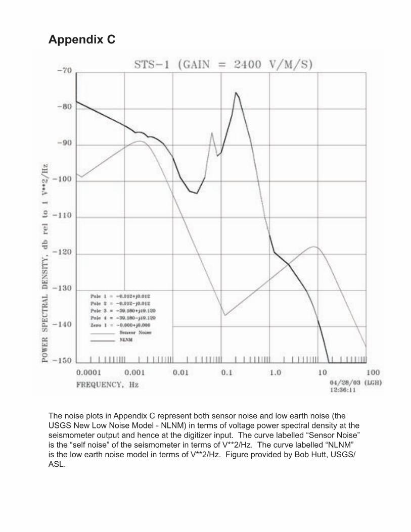
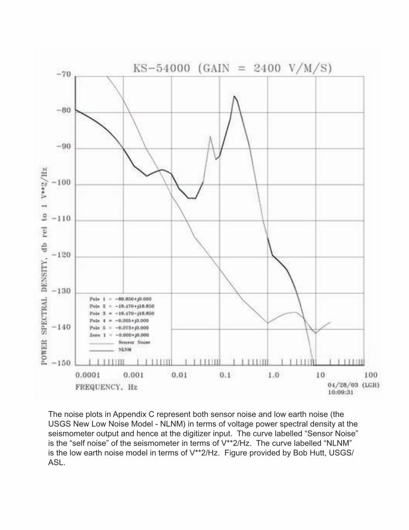
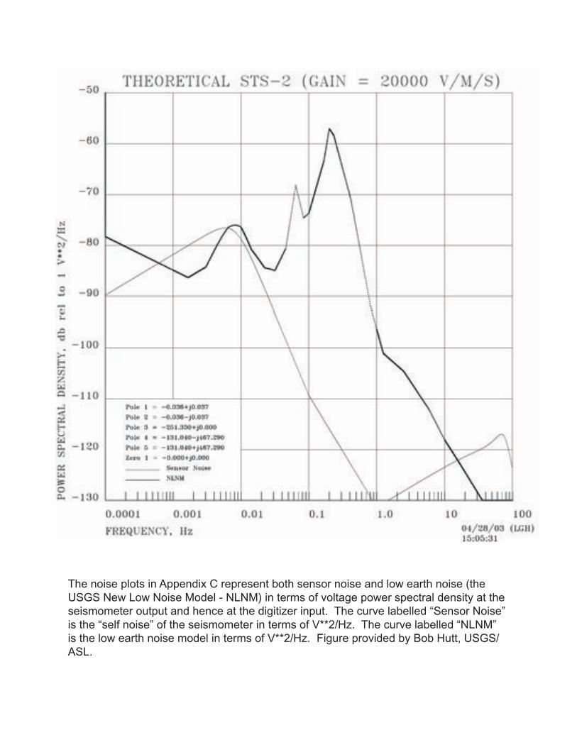
The noise plots in Appendix C represent both sensor noise and low earth noise (the USGS New Low Noise Model - NLNM) in terms of voltage power spectral density at the seismometer output and hence at the digitizer input. The curve labelled “Sensor Noise” is the “self noise” of the seismometer in terms of V**2/Hz. The curve labelled “NLNM” is the low earth noise model in terms of V**2/Hz. Figure provided by Bob Hutt, USGS/ASL.
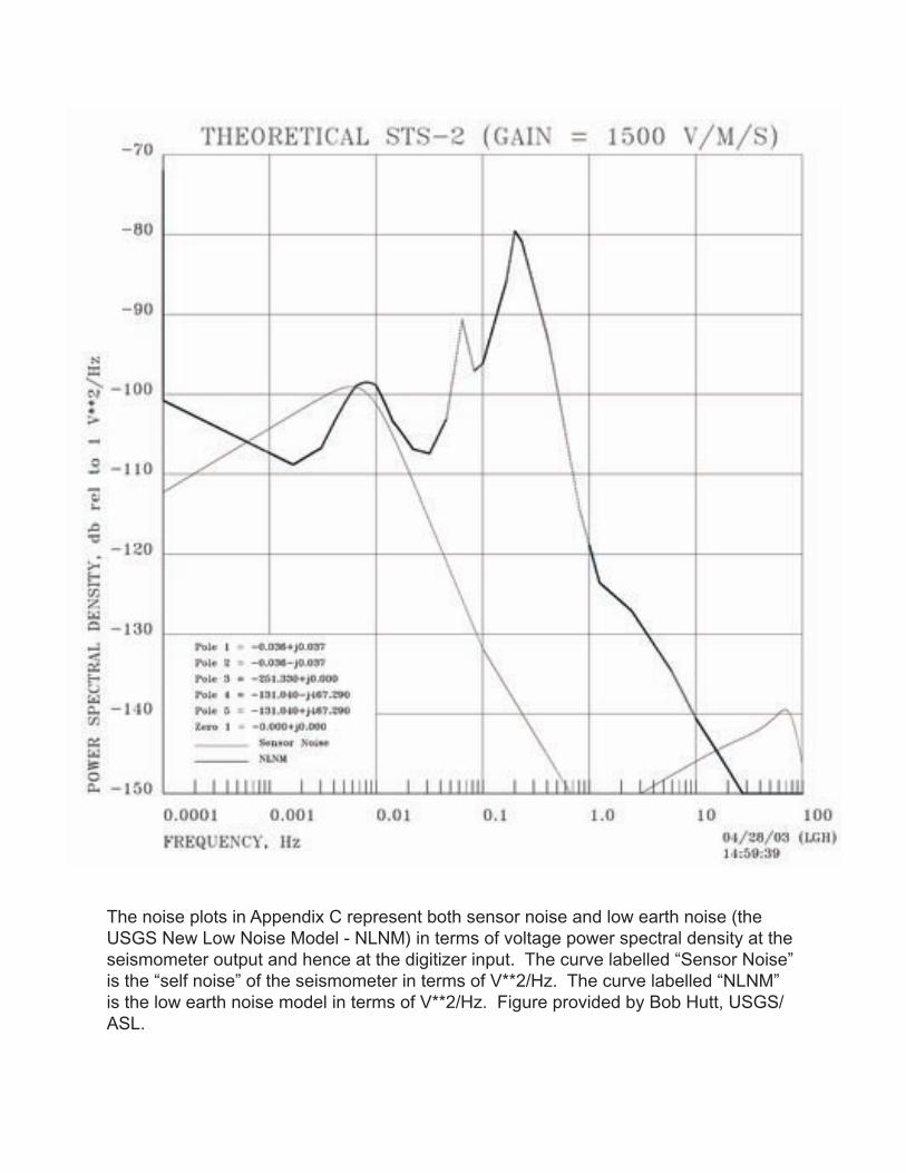
The noise plots in Appendix C represent both sensor noise and low earth noise (the USGS New Low Noise Model - NLNM) in terms of voltage power spectral density at the seismometer output and hence at the digitizer input. The curve labelled “Sensor Noise” is the “self noise” of the seismometer in terms of V**2/Hz. The curve labelled “NLNM” is the low earth noise model in terms of V**2/Hz. Figure provided by Bob Hutt, USGS/ASL.
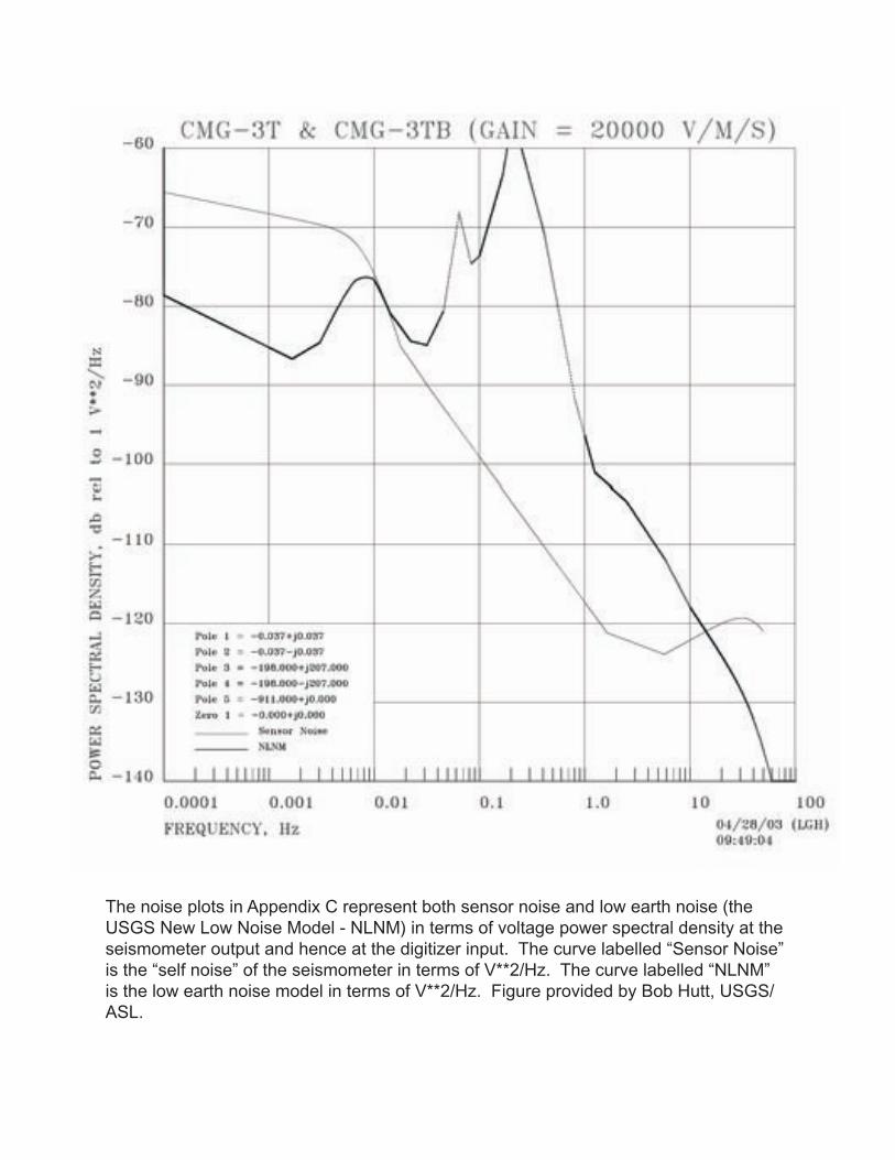
The noise plots in Appendix C represent both sensor noise and low earth noise (the USGS New Low Noise Model - NLNM) in terms of voltage power spectral density at the seismometer output and hence at the digitizer input. The curve labelled “Sensor Noise” is the “self noise” of the seismometer in terms of V**2/Hz. The curve labelled “NLNM” is the low earth noise model in terms of V**2/Hz. Figure provided by Bob Hutt, USGS/ASL.
The noise plots in Appendix C represent both sensor noise and low earth noise (the USGS New Low Noise Model - NLNM) in terms of voltage power spectral density at the seismometer output and hence at the digitizer input. The curve labelled “Sensor Noise” is the “self noise” of the seismometer in terms of V**2/Hz. The curve labelled “NLNM” is the low earth noise model in terms of V**2/Hz. Figure provided by Bob Hutt, USGS/ASL.
The noise plots in Appendix C represent both sensor noise and low earth noise (the USGS New Low Noise Model - NLNM) in terms of voltage power spectral density at the seismometer output and hence at the digitizer input. The curve labelled “Sensor Noise” is the “self noise” of the seismometer in terms of V**2/Hz. The curve labelled “NLNM” is the low earth noise model in terms of V**2/Hz. Figure provided by Bob Hutt, USGS/ASL.