global buckling analsysis of cylindrical liquid … · 1 . global buckling analsysis of cylindrical...
TRANSCRIPT
1
GLOBAL BUCKLING ANALSYSIS OF CYLINDRICAL LIQUID STORAGE TANKS UNDER EARTHQUAKE LOADING
Julia ROSIN1 and Benedikt HENNEBOEHL2 and Christoph BUTENWEG3
ABSTRACT
Cylindrical steel tanks are a rather economical supporting structure for the storing of liquids. However, because of their thin-walled and slender structure, they are highly vulnerable to shell buckling. Especially in case of an earthquake, structural safety is highly endangered due to additional axial and shear forces in the tank wall caused by the movement of the contained liquid. At the same time secondary damages as a result of a possible collapse are disastrous.
The European code DIN EN 1993-1-6 permits three different approaches for the buckling strength verification of shell structures, which differ according to their numerical effort. The well-known stress based verification is the traditional concept, which, however, reaches its limits for the special case of seismically loaded tank structures. Here the numerical concepts represent a very promising alternative, although their application is connected with several questionable points. Within this paper the numerical based buckling analyses according to DIN EN 1993-1-6 are investigated concerning their application for seismically loaded tank structures. Reached
INTRODUCTION
Thin walled steel tanks are used in many seismically active regions around the world, whether as general storage structures or as part of industrial facilities. In the event of strong earthquakes, it is important that the structural integrity of tanks containing liquids is maintained, in order to not jeopardize the population's supply with essential goods. Recent earthquake events have shown that heavy seismic damages of tanks may lead to environmental hazards, fire following earthquakes and temporary loss of essential facilities. Liquid storage tanks are preferably designed as cylindrical shells, because they are able to carry the hydrostatic pressure from the liquid filling by activating membrane stresses with a minimum of material. In combination with the high strength of steel this leads to thin-walled constructions, which are highly vulnerable to stability failures caused by seismic induced axial and shear forces.
For the analysis of the stability of tanks the European Standard for Shell Strength and Stability (DIN EN 1993-1-6, 2010) proposes three different analysis concepts: a buckling safety analysis based on stresses and two different numerically supported concepts. The stress based buckling safety analysis is the traditional concept, which compares stresses given by a simple linear analysis (LA) with algebraic hand calculation strength assessment rules on the basis of experimental background. In
1 Dipl.-Ing., Chair of Structural Analysis and Dynamics, RWTH Aachen University, Aachen/Germany, [email protected] 2 M.Sc., Chair of Structural Analysis and Dynamics, RWTH Aachen University, Aachen/Germany, [email protected] 3 Dr.-Ing., Chair of Structural Analysis and Dynamics, RWTH Aachen University, Aachen/Germany, [email protected]
2
addition to this, DIN EN 1993-1 (2010) proposes two innovative analysis concepts, that base on a numerical analysis of the global tank structure: the combination of a linear bifurcation analysis (LBA) with a material nonlinear analysis (MNA) of the geometrically perfect shell is the simpler one. The more accurate but also the most complex and elaborate concept bases on a full-fledged nonlinear calculation of the shell considering geometrically and materially nonlinearities as well as adequately dimensioned imperfections (GMNIA).
As seismically loaded tanks are exposed to a stress state induced by combined loads the traditional stress-based verification concept is not really convenient. Anyway, it is still the mostly used verification concept, because the application of the alternative concepts in some points is rather problematic. The present paper demonstrates the application of the nonlinear design procedures to seismically loaded tank structures and discusses several highly questionable elements.
SEISMICALLY AFFECTED LIQUID STORAGE TANKS
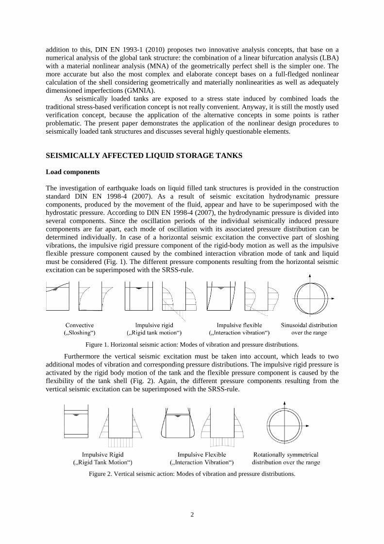
Load components The investigation of earthquake loads on liquid filled tank structures is provided in the construction standard DIN EN 1998-4 (2007). As a result of seismic excitation hydrodynamic pressure components, produced by the movement of the fluid, appear and have to be superimposed with the hydrostatic pressure. According to DIN EN 1998-4 (2007), the hydrodynamic pressure is divided into several components. Since the oscillation periods of the individual seismically induced pressure components are far apart, each mode of oscillation with its associated pressure distribution can be determined individually. In case of a horizontal seismic excitation the convective part of sloshing vibrations, the impulsive rigid pressure component of the rigid-body motion as well as the impulsive flexible pressure component caused by the combined interaction vibration mode of tank and liquid must be considered (Fig. 1). The different pressure components resulting from the horizontal seismic excitation can be superimposed with the SRSS-rule.
Figure 1. Horizontal seismic action: Modes of vibration and pressure distributions.
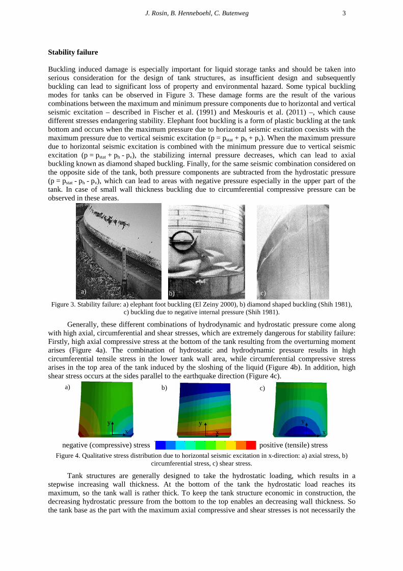
Furthermore the vertical seismic excitation must be taken into account, which leads to two additional modes of vibration and corresponding pressure distributions. The impulsive rigid pressure is activated by the rigid body motion of the tank and the flexible pressure component is caused by the flexibility of the tank shell (Fig. 2). Again, the different pressure components resulting from the vertical seismic excitation can be superimposed with the SRSS-rule.
Figure 2. Vertical seismic action: Modes of vibration and pressure distributions.
J. Rosin, B. Henneboehl, C. Butenweg 3
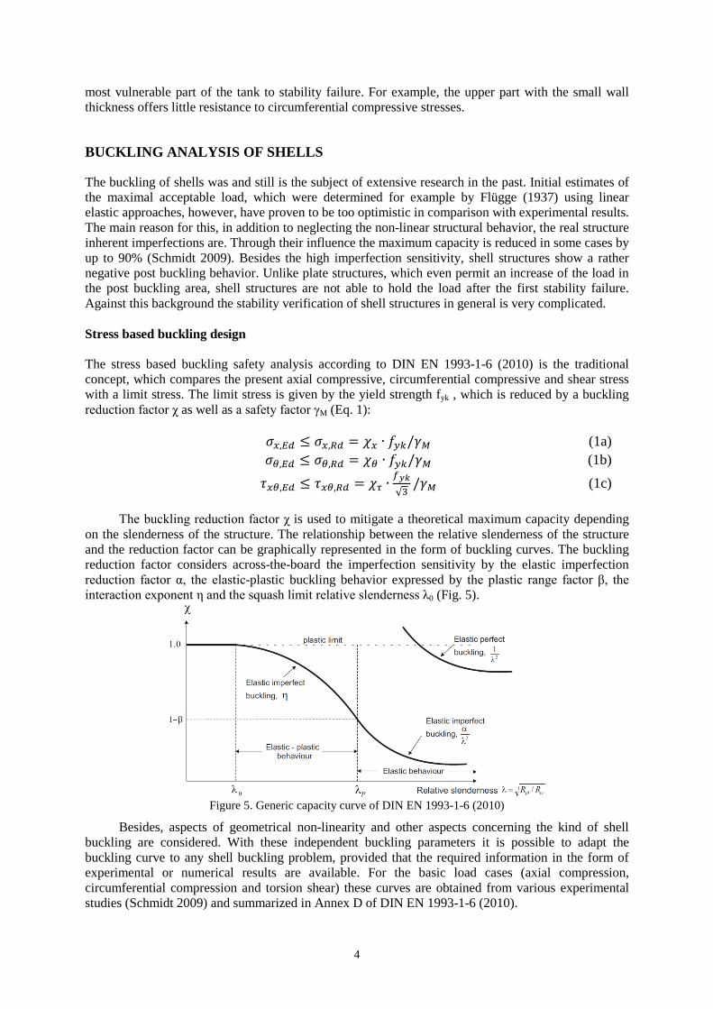
Stability failure Buckling induced damage is especially important for liquid storage tanks and should be taken into serious consideration for the design of tank structures, as insufficient design and subsequently buckling can lead to significant loss of property and environmental hazard. Some typical buckling modes for tanks can be observed in Figure 3. These damage forms are the result of the various combinations between the maximum and minimum pressure components due to horizontal and vertical seismic excitation – described in Fischer et al. (1991) and Meskouris et al. (2011) –, which cause different stresses endangering stability. Elephant foot buckling is a form of plastic buckling at the tank bottom and occurs when the maximum pressure due to horizontal seismic excitation coexists with the maximum pressure due to vertical seismic excitation (p = pstat + ph + pv). When the maximum pressure due to horizontal seismic excitation is combined with the minimum pressure due to vertical seismic excitation (p = pstat + ph - pv), the stabilizing internal pressure decreases, which can lead to axial buckling known as diamond shaped buckling. Finally, for the same seismic combination considered on the opposite side of the tank, both pressure components are subtracted from the hydrostatic pressure (p = pstat - ph - pv), which can lead to areas with negative pressure especially in the upper part of the tank. In case of small wall thickness buckling due to circumferential compressive pressure can be observed in these areas.
Figure 3. Stability failure: a) elephant foot buckling (El Zeiny 2000), b) diamond shaped buckling (Shih 1981),
c) buckling due to negative internal pressure (Shih 1981).
Generally, these different combinations of hydrodynamic and hydrostatic pressure come along with high axial, circumferential and shear stresses, which are extremely dangerous for stability failure: Firstly, high axial compressive stress at the bottom of the tank resulting from the overturning moment arises (Figure 4a). The combination of hydrostatic and hydrodynamic pressure results in high circumferential tensile stress in the lower tank wall area, while circumferential compressive stress arises in the top area of the tank induced by the sloshing of the liquid (Figure 4b). In addition, high shear stress occurs at the sides parallel to the earthquake direction (Figure 4c).
negative (compressive) stress positive (tensile) stress
Figure 4. Qualitative stress distribution due to horizontal seismic excitation in x-direction: a) axial stress, b) circumferential stress, c) shear stress.
Tank structures are generally designed to take the hydrostatic loading, which results in a stepwise increasing wall thickness. At the bottom of the tank the hydrostatic load reaches its maximum, so the tank wall is rather thick. To keep the tank structure economic in construction, the decreasing hydrostatic pressure from the bottom to the top enables an decreasing wall thickness. So the tank base as the part with the maximum axial compressive and shear stresses is not necessarily the
a) b) c)
x y
x y x
y
b) c) a)
4
most vulnerable part of the tank to stability failure. For example, the upper part with the small wall thickness offers little resistance to circumferential compressive stresses.
BUCKLING ANALYSIS OF SHELLS
The buckling of shells was and still is the subject of extensive research in the past. Initial estimates of the maximal acceptable load, which were determined for example by Flügge (1937) using linear elastic approaches, however, have proven to be too optimistic in comparison with experimental results. The main reason for this, in addition to neglecting the non-linear structural behavior, the real structure inherent imperfections are. Through their influence the maximum capacity is reduced in some cases by up to 90% (Schmidt 2009). Besides the high imperfection sensitivity, shell structures show a rather negative post buckling behavior. Unlike plate structures, which even permit an increase of the load in the post buckling area, shell structures are not able to hold the load after the first stability failure. Against this background the stability verification of shell structures in general is very complicated. Stress based buckling design The stress based buckling safety analysis according to DIN EN 1993-1-6 (2010) is the traditional concept, which compares the present axial compressive, circumferential compressive and shear stress with a limit stress. The limit stress is given by the yield strength fyk , which is reduced by a buckling reduction factor χ as well as a safety factor γM (Eq. 1): 𝜎𝑥,𝐸𝑑 ≤ 𝜎𝑥,𝑅𝑑 = 𝜒𝑥 ∙ 𝑓𝑦𝑘/𝛾𝑀 (1a) 𝜎𝜃,𝐸𝑑 ≤ 𝜎𝜃,𝑅𝑑 = 𝜒𝜃 ∙ 𝑓𝑦𝑘/𝛾𝑀 (1b) 𝜏𝑥𝜃,𝐸𝑑 ≤ 𝜏𝑥𝜃,𝑅𝑑 = 𝜒𝜏 ∙
𝑓𝑦𝑘√3
/𝛾𝑀 (1c)
The buckling reduction factor χ is used to mitigate a theoretical maximum capacity depending on the slenderness of the structure. The relationship between the relative slenderness of the structure and the reduction factor can be graphically represented in the form of buckling curves. The buckling reduction factor considers across-the-board the imperfection sensitivity by the elastic imperfection reduction factor α, the elastic-plastic buckling behavior expressed by the plastic range factor β, the interaction exponent η and the squash limit relative slenderness λ0 (Fig. 5).
Figure 5. Generic capacity curve of DIN EN 1993-1-6 (2010)
Besides, aspects of geometrical non-linearity and other aspects concerning the kind of shell buckling are considered. With these independent buckling parameters it is possible to adapt the buckling curve to any shell buckling problem, provided that the required information in the form of experimental or numerical results are available. For the basic load cases (axial compression, circumferential compression and torsion shear) these curves are obtained from various experimental studies (Schmidt 2009) and summarized in Annex D of DIN EN 1993-1-6 (2010).
J. Rosin, B. Henneboehl, C. Butenweg 5
To consider the special load situation of a liquid filled tank DIN EN 1993-1-6 (2010) gives the possibility to capture the influence of the circumferential tensile stresses caused by the hydrostatic pressure. In this case, the axial compressive reduction factor is modified. Here, the elastic stabilizing effect caused by the internal pressure as well as their plastic destabilizing effect is considered.
In Addition, DIN EN 1993-1-6 (2010) allows an interaction verification. The interaction analysis of the stress based analysis concept, which has to be conducted as soon as more than one of the three stress components relevant for buckling strains the shell, is composed of the compound separate analyses combined with interaction parameters for buckling (Eq. 2):
�𝜎𝑥,𝐸𝑑𝜎𝑥,𝑅𝑑
�𝑘𝑥− 𝑘𝑖 ∙ �
𝜎𝑥,𝐸𝑑𝜎𝑥,𝑅𝑑
� ∙ �𝜎𝜃,𝐸𝑑𝜎𝜃,𝑅𝑑
� + �𝜎𝜃,𝐸𝑑𝜎𝜃,𝑅𝑑
�𝑘𝜃
+ �𝜏𝑥𝜃,𝐸𝑑𝜏𝑥𝜃,𝑅𝑑
�𝑘𝜏≤ 1,0 (2)
The buckling interaction parameters base on theoretical approaches and cover not only the
interaction of very thin, elastic buckling shells but also the plastic buckling behavior of very thick walled shells. Thereby the parameters are rather conservative.
The stress based buckling verification is well-suited for cylindrical shells under uniform stress state, e.g. only circumferential compression or only axial compression or only torsion shear stress. However, as shown before due to seismic excitation the tank structure is strained by combined stresses. In this case the stability analysis of three individual and independent stresses is not adequate anymore.
Even both modified possibilities considering the combined stresses occurring within the shell, which are the utilization of the positive influence of circumferential tensile stresses as well as the interaction verification, are not suitable for the special situation of a seismically loaded tank.
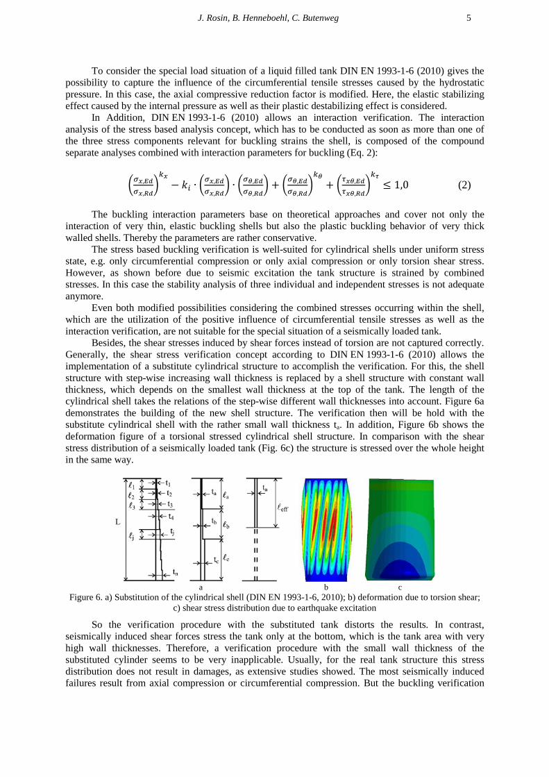
Besides, the shear stresses induced by shear forces instead of torsion are not captured correctly. Generally, the shear stress verification concept according to DIN EN 1993-1-6 (2010) allows the implementation of a substitute cylindrical structure to accomplish the verification. For this, the shell structure with step-wise increasing wall thickness is replaced by a shell structure with constant wall thickness, which depends on the smallest wall thickness at the top of the tank. The length of the cylindrical shell takes the relations of the step-wise different wall thicknesses into account. Figure 6a demonstrates the building of the new shell structure. The verification then will be hold with the substitute cylindrical shell with the rather small wall thickness ta. In addition, Figure 6b shows the deformation figure of a torsional stressed cylindrical shell structure. In comparison with the shear stress distribution of a seismically loaded tank (Fig. 6c) the structure is stressed over the whole height in the same way.
a b c
Figure 6. a) Substitution of the cylindrical shell (DIN EN 1993-1-6, 2010); b) deformation due to torsion shear; c) shear stress distribution due to earthquake excitation
So the verification procedure with the substituted tank distorts the results. In contrast, seismically induced shear forces stress the tank only at the bottom, which is the tank area with very high wall thicknesses. Therefore, a verification procedure with the small wall thickness of the substituted cylinder seems to be very inapplicable. Usually, for the real tank structure this stress distribution does not result in damages, as extensive studies showed. The most seismically induced failures result from axial compression or circumferential compression. But the buckling verification
6
according to the stress based concept of DIN EN 1993-1-is governed by the rather conservative results for the shear stress verification.
Summarized, the application of the stress based buckling analysis to seismic excited tanks has got several significant deficits.
Numerical based buckling design using the LBA/MNA approach
Here, DIN EN 1993-1 (2010) proposes two innovative analysis concepts, that base on a numerical analysis of the global tank structure: the combination of a linear bifurcation analysis (LBA) with a material non-linear analysis (MNA) of the geometrically perfect shell is the simpler one. The more accurate but also the most complex and elaborate concept bases on a full-fledged nonlinear calculation of the shell considering geometrically and materially nonlinearities as well as adequately dimensioned imperfections (GMNIA). The result of both analysis concepts is a buckling resistance value (load factor), which has to be greater than 1.0. This value has to be understood as the structure’s safety against stability failure under a specific combination of loads.
The LBA-MNA-concept bases on a calculation of the perfect shell. Using a linear bifurcation analysis (LBA) the lowest load factor is set as ideal elastic buckling resistance rRcr. The material nonlinear analysis (MNA) provides information on the plastic limit load rRpl. Both numerically determined parameters are combined to the referred slenderness λov of the whole structure (index “ov” means “overall”), which is needed for the determination of the buckling reduction factor χov. With the buckling reduction factor the plastic collapse load factor is reduced to the characteristic buckling resistance rRk. Here, the buckling reduction factors of the basis buckling modes of the stress based verification concept are used.
So the first sticking-point of the analysis is the determination of the buckling reduction factor. It is a global parameter for the whole shell structure, which considers across-the-board the imperfection sensitiveness by the elastic imperfection reduction factor α, the elastic-plastic buckling behavior expressed by the plastic range factor β, the interaction exponent η and the squash limit relative slenderness λ0 (Fig. 5). The selection of the buckling reduction factor for the whole shell is decisive for further analyses and the values must be estimated by the engineer, using similar load cases and similar shell geometries as guides (Rotter, 2011a), but especially for seismic excited tanks no global buckling factors exist for this special case of shell buckling.
Another problem is identified by Schmidt (2009) and described in Rotter (2011a). If the lowest elastic critical buckling condition (rRcr1) occurs in a segment of the structure that is not imperfection sensitive but another eigenvalue is only slightly higher (rRcr2 > rRcr1) with its eigenmode affecting an imperfection sensitive segment (α2⋅rRcr2 < α1⋅rRcr1), it is important that the latter is identified for safe design. Numerical based buckling design using the GMNIA approach In the previous presented analysis concepts imperfections are across-the-board recorded within the buckling reduction curves. So an explicit modeling within the calculations is not necessary. If their effect, however, has to be analyzed in more detail, this can be done within the framework of a geometrically and materially nonlinear analysis of the imperfect shell model (GMNIA).
In this calculation method particular attention should be paid to the choice of imperfections. The large number of possible buckling modes with almost the same load level in conjunction with the strong load decrease in the post-buckling causes a high imperfection sensitivity of thin-walled shell structures. The applied imperfections should influence the structural behavior of the shell in the most negative way, but the application is very sensitive as they affect different shell geometries and load cases to different extents and even for well-defined geometry their effect is strongly dependent on their form and their amplitude (Rotter, 2011a). Actually, only shell structures under uniform stress state have been investigated extensively. Here, collapse affine imperfections have been applied to the shell. These imperfections are based on the failure mode of the perfect shell and therefore cover the weaknesses of the shell at a given load. Eigenmode equivalent imperfections as specified by the DIN EN 1993-1-6 (2010) have been found to be unsuitable in several studies.
J. Rosin, B. Henneboehl, C. Butenweg 7
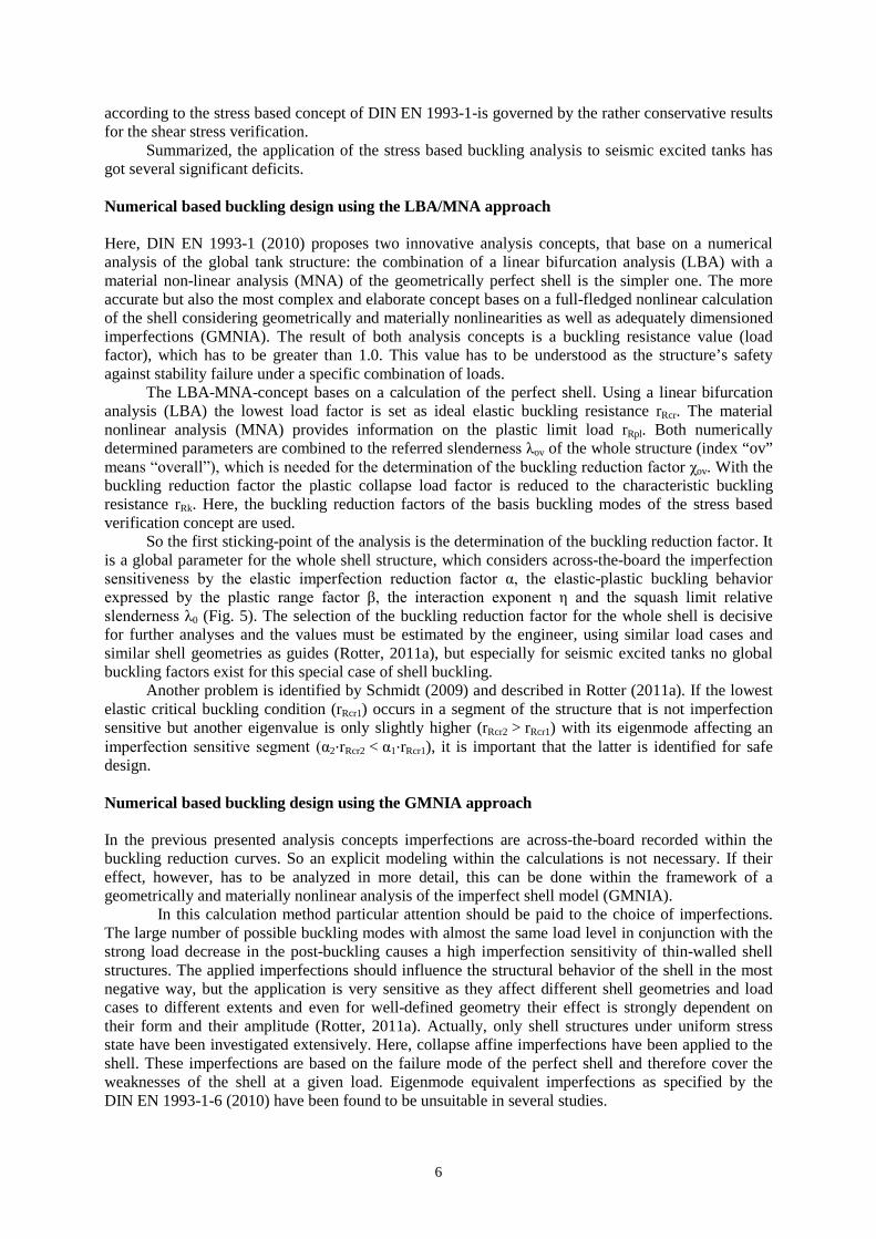
For axial buckling a rotationally symmetric convex cycle imperfection is placed at the location of the maximum axial compressive stress (Gettel, 2008, Fig. 7a). For circumferential buckling a concave longitudinal imperfection is to be set, which enfolds about 5/6 of the tank shell height (Schneider and Gettel 2011). A fixed concave longitudinal imperfection should be avoided due to numerical difficulties and lack of instability points. More advantageous is the natural longitudinal buckle shown in Figure 7b, which is adapted to the natural decay of bending disturbances in the circumferential direction. Shear buckling together with the consideration of imperfections has so far been investigated fragmentary. It is a stability failure as a result of slope buckles, which are difficult to model. So for simplicity, reference is made to a natural longitudinal buckle. It is formed as convex longitudinal imperfection, again following the natural decay of bending disturbances (Gettel, 2008, Fig. 7c).
a b c Figure 7. a: rotationally symmetric convex cycle imperfection; b: natural concave longitudinal
imperfection; c: natural convex longitudinal imperfection
These imperfections which have been developed for the three basis buckling modes can be used for a combined stressed shell structure as well. In this case every imperfection form has to be investigated separately and at the end the one with the most negative influence of the stability behavior is decisive.
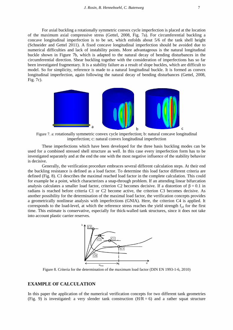
Generally, the verification procedure embraces several different calculation steps. At their end the buckling resistance is defined as a load factor. To determine this load factor different criteria are defined (Fig. 8). C1 describes the maximal reached load factor in the complete calculation. This could for example be a point, which characterizes a snap-through problem. If an attending linear bifurcation analysis calculates a smaller load factor, criterion C2 becomes decisive. If a distortion of β = 0.1 in radians is reached before criteria C1 or C2 become active, the criterion C3 becomes decisive. As another possibility for the determination of the maximal load factor, the verification concepts provides a geometrically nonlinear analysis with imperfections (GNIA). Here, the criterion C4 is applied. It corresponds to the load-level, at which the reference stress reaches the yield strength fyd for the first time. This estimate is conservative, especially for thick-walled tank structures, since it does not take into account plastic carrier reserves.
Figure 8. Criteria for the determination of the maximum load factor (DIN EN 1993-1-6, 2010)
EXAMPLE OF CALCULATION
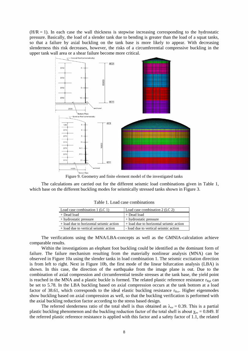
In this paper the application of the numerical verification concepts for two different tank geometries (Fig. 9) is investigated: a very slender tank construction (H/R = 6) and a rather squat structure
rλ
uumax
8
(H/R = 1). In each case the wall thickness is stepwise increasing corresponding to the hydrostatic pressure. Basically, the load of a slender tank due to bending is greater than the load of a squat tanks, so that a failure by axial buckling on the tank base is more likely to appear. With decreasing slenderness this risk decreases, however, the risks of a circumferential compressive buckling in the upper tank wall area or a shear failure become more critical.
Figure 9. Geometry and finite element model of the investigated tanks
The calculations are carried out for the different seismic load combinations given in Table 1, which base on the different buckling modes for seismically stressed tanks shown in Figure 3.
Table 1. Load case combinations Load case combination 1 (LC 1) Load case combination 2 (LC 2) + Dead load + Dead load + hydrostatic pressure + hydrostatic pressure + load due to horizontal seismic action + load due to horizontal seismic action + load due to vertical seismic action - load due to vertical seismic action
The verifications using the MNA/LBA-concepts as well as the GMNIA-calculation achieve
comparable results. Within the investigations an elephant foot buckling could be identified as the dominant form of
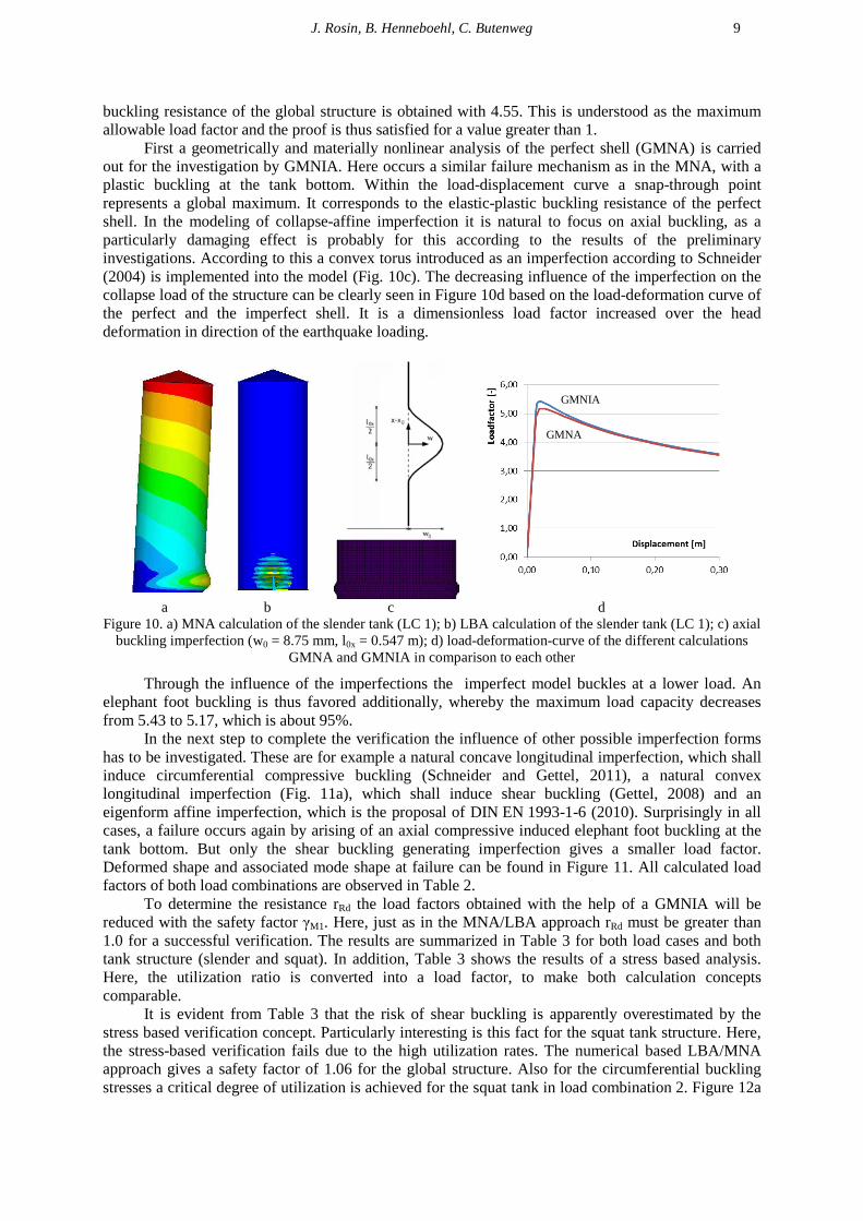
failure. The failure mechanism resulting from the materially nonlinear analysis (MNA) can be observed in Figure 10a using the slender tanks in load combination 1. The seismic excitation direction is from left to right. Next in Figure 10b, the first mode of the linear bifurcation analysis (LBA) is shown. In this case, the direction of the earthquake from the image plane is out. Due to the combination of axial compression and circumferential tensile stresses at the tank base, the yield point is reached in the MNA and a plastic buckle is formed. The related plastic reference resistance rRpl can be set to 5.78. In the LBA buckling based on axial compression occurs at the tank bottom at a load factor of 38.61, which corresponds to the ideal elastic buckling resistance rRcr. Higher eigenmodes show buckling based on axial compression as well, so that the buckling verification is performed with the axial buckling reduction factor according to the stress based design.
The referred slenderness ratio of the total shell is thus obtained as λov = 0.39. This is a partial plastic buckling phenomenon and the buckling reduction factor of the total shell is about χov = 0.849. If the referred plastic reference resistance is applied with this factor and a safety factor of 1.1, the related
J. Rosin, B. Henneboehl, C. Butenweg 9
buckling resistance of the global structure is obtained with 4.55. This is understood as the maximum allowable load factor and the proof is thus satisfied for a value greater than 1.
First a geometrically and materially nonlinear analysis of the perfect shell (GMNA) is carried out for the investigation by GMNIA. Here occurs a similar failure mechanism as in the MNA, with a plastic buckling at the tank bottom. Within the load-displacement curve a snap-through point represents a global maximum. It corresponds to the elastic-plastic buckling resistance of the perfect shell. In the modeling of collapse-affine imperfection it is natural to focus on axial buckling, as a particularly damaging effect is probably for this according to the results of the preliminary investigations. According to this a convex torus introduced as an imperfection according to Schneider (2004) is implemented into the model (Fig. 10c). The decreasing influence of the imperfection on the collapse load of the structure can be clearly seen in Figure 10d based on the load-deformation curve of the perfect and the imperfect shell. It is a dimensionless load factor increased over the head deformation in direction of the earthquake loading.
a b c d Figure 10. a) MNA calculation of the slender tank (LC 1); b) LBA calculation of the slender tank (LC 1); c) axial
buckling imperfection (w0 = 8.75 mm, l0x = 0.547 m); d) load-deformation-curve of the different calculations GMNA and GMNIA in comparison to each other
Through the influence of the imperfections the imperfect model buckles at a lower load. An elephant foot buckling is thus favored additionally, whereby the maximum load capacity decreases from 5.43 to 5.17, which is about 95%.
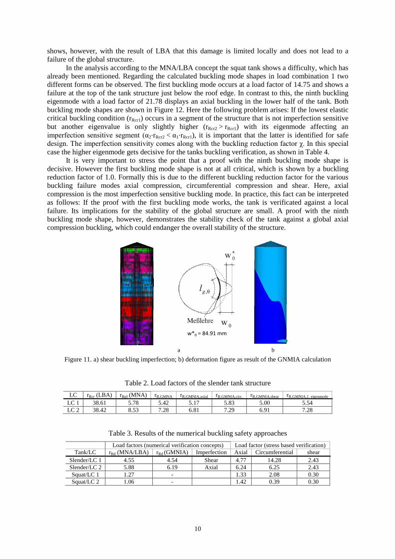
In the next step to complete the verification the influence of other possible imperfection forms has to be investigated. These are for example a natural concave longitudinal imperfection, which shall induce circumferential compressive buckling (Schneider and Gettel, 2011), a natural convex longitudinal imperfection (Fig. 11a), which shall induce shear buckling (Gettel, 2008) and an eigenform affine imperfection, which is the proposal of DIN EN 1993-1-6 (2010). Surprisingly in all cases, a failure occurs again by arising of an axial compressive induced elephant foot buckling at the tank bottom. But only the shear buckling generating imperfection gives a smaller load factor. Deformed shape and associated mode shape at failure can be found in Figure 11. All calculated load factors of both load combinations are observed in Table 2.
To determine the resistance rRd the load factors obtained with the help of a GMNIA will be reduced with the safety factor γM1. Here, just as in the MNA/LBA approach rRd must be greater than 1.0 for a successful verification. The results are summarized in Table 3 for both load cases and both tank structure (slender and squat). In addition, Table 3 shows the results of a stress based analysis. Here, the utilization ratio is converted into a load factor, to make both calculation concepts comparable.
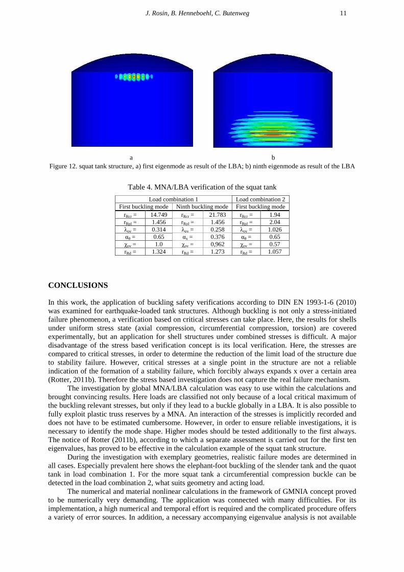
It is evident from Table 3 that the risk of shear buckling is apparently overestimated by the stress based verification concept. Particularly interesting is this fact for the squat tank structure. Here, the stress-based verification fails due to the high utilization rates. The numerical based LBA/MNA approach gives a safety factor of 1.06 for the global structure. Also for the circumferential buckling stresses a critical degree of utilization is achieved for the squat tank in load combination 2. Figure 12a
GMNA
GMNIA
10
shows, however, with the result of LBA that this damage is limited locally and does not lead to a failure of the global structure.
In the analysis according to the MNA/LBA concept the squat tank shows a difficulty, which has already been mentioned. Regarding the calculated buckling mode shapes in load combination 1 two different forms can be observed. The first buckling mode occurs at a load factor of 14.75 and shows a failure at the top of the tank structure just below the roof edge. In contrast to this, the ninth buckling eigenmode with a load factor of 21.78 displays an axial buckling in the lower half of the tank. Both buckling mode shapes are shown in Figure 12. Here the following problem arises: If the lowest elastic critical buckling condition (rRcr1) occurs in a segment of the structure that is not imperfection sensitive but another eigenvalue is only slightly higher (rRcr2 > rRcr1) with its eigenmode affecting an imperfection sensitive segment (α2⋅rRcr2 < α1⋅rRcr1), it is important that the latter is identified for safe design. The imperfection sensitivity comes along with the buckling reduction factor χ. In this special case the higher eigenmode gets decisive for the tanks buckling verification, as shown in Table 4.
It is very important to stress the point that a proof with the ninth buckling mode shape is decisive. However the first buckling mode shape is not at all critical, which is shown by a buckling reduction factor of 1.0. Formally this is due to the different buckling reduction factor for the various buckling failure modes axial compression, circumferential compression and shear. Here, axial compression is the most imperfection sensitive buckling mode. In practice, this fact can be interpreted as follows: If the proof with the first buckling mode works, the tank is verificated against a local failure. Its implications for the stability of the global structure are small. A proof with the ninth buckling mode shape, however, demonstrates the stability check of the tank against a global axial compression buckling, which could endanger the overall stability of the structure.
w*0 = 84.91 mm
a b
Figure 11. a) shear buckling imperfection; b) deformation figure as result of the GNMIA calculation
Table 2. Load factors of the slender tank structure LC rRcr (LBA) rRpl (MNA) rR,GMNA rR,GMNIA,axial rR,GMNIA,circ. rR,GMNIA,shear rR,GMNIA,1. eigenmode
LC 1 38.61 5.78 5.42 5.17 5.83 5.00 5.54 LC 2 38.42 8.53 7.28 6.81 7.29 6.91 7.28
Table 3. Results of the numerical buckling safety approaches Load factors (numerical verification concepts) Load factor (stress based verification)
Tank/LC rRd (MNA/LBA) rRd (GMNIA) Imperfection Axial Circumferential shear Slender/LC 1 4.55 4.54 Shear 4.77 14.28 2.43 Slender/LC 2 5.88 6.19 Axial 6.24 6.25 2.43 Squat/LC 1 1.27 - 1.33 2.08 0.30 Squat/LC 2 1.06 - 1.42 0.39 0.30
J. Rosin, B. Henneboehl, C. Butenweg 11
a b
Figure 12. squat tank structure, a) first eigenmode as result of the LBA; b) ninth eigenmode as result of the LBA
Table 4. MNA/LBA verification of the squat tank
Load combination 1 Load combination 2 First buckling mode Ninth buckling mode First buckling mode
rRcr = 14.749 rRcr = 21.783 rRcr = 1.94 rRpl = 1.456 rRpl = 1.456 rRpl = 2.04 λov = 0.314 λov = 0.258 λov = 1.026 αθ = 0.65 αx = 0.376 αθ = 0.65 χov = 1.0 χov = 0,962 χov = 0.57 rRd = 1.324 rRd = 1.273 rRd = 1.057
CONCLUSIONS
In this work, the application of buckling safety verifications according to DIN EN 1993-1-6 (2010) was examined for earthquake-loaded tank structures. Although buckling is not only a stress-initiated failure phenomenon, a verification based on critical stresses can take place. Here, the results for shells under uniform stress state (axial compression, circumferential compression, torsion) are covered experimentally, but an application for shell structures under combined stresses is difficult. A major disadvantage of the stress based verification concept is its local verification. Here, the stresses are compared to critical stresses, in order to determine the reduction of the limit load of the structure due to stability failure. However, critical stresses at a single point in the structure are not a reliable indication of the formation of a stability failure, which forcibly always expands x over a certain area (Rotter, 2011b). Therefore the stress based investigation does not capture the real failure mechanism.
The investigation by global MNA/LBA calculation was easy to use within the calculations and brought convincing results. Here loads are classified not only because of a local critical maximum of the buckling relevant stresses, but only if they lead to a buckle globally in a LBA. It is also possible to fully exploit plastic truss reserves by a MNA. An interaction of the stresses is implicitly recorded and does not have to be estimated cumbersome. However, in order to ensure reliable investigations, it is necessary to identify the mode shape. Higher modes should be tested additionally to the first always. The notice of Rotter (2011b), according to which a separate assessment is carried out for the first ten eigenvalues, has proved to be effective in the calculation example of the squat tank structure.
During the investigation with exemplary geometries, realistic failure modes are determined in all cases. Especially prevalent here shows the elephant-foot buckling of the slender tank and the quaot tank in load combination 1. For the more squat tank a circumferential compression buckle can be detected in the load combination 2, what suits geometry and acting load.
The numerical and material nonlinear calculations in the framework of GMNIA concept proved to be numerically very demanding. The application was connected with many difficulties. For its implementation, a high numerical and temporal effort is required and the complicated procedure offers a variety of error sources. In addition, a necessary accompanying eigenvalue analysis is not available
12
by default in the used finite element software and has to be implemented in an additional calculation step. Despite these difficulties, should be dispensed with the approach of eigenmode-affine imperfections according to specification of the standard, as these have proven to be largely ineffect. Instead, consistent geometric imperfections according to Schneider (2004) should be chosen.
Summarized, the overall results of the stress based evidence compared to the proof required by nonlinear calculations are very conservative. By means of a more accurate calculation, the maximum load capacity could be significantly increased. As the calculations on the slender tank example demonstrates the load factors obtained by a fully nonlinear analysis by use of the GMNIA reach almost the same level as an MNA/LBA calculation. Due to the overhead in calculating the accurate modeling and analysis no more information can be obtained. Here, the investigation with the MNA/LBA concept is preferable due to its much more user-friendly handling in comparison to a geometrically and materially nonlinear analysis of imperfect shell (GMNIA).
REFERENCES
DIN EN 1993-1-6 (2010) “Bemessung und Konstruktion von Stahlbauten – Festigkeit und Stabilität von Schalen”, Deutsches Institut für Normung, Berlin
DIN EN 1998-4 (2007) “Auslegung von Bauwerken gegen Erdbeben – Silos, Tankbauwerke und Rohrleitungen”, Deutsches Institut für Normung, Berlin
El-Zeiny AA (1995) Nonlinear Time-Dependent Seismic Response of Unanchored Liquid Storage Tanks, Ph.D. Thesis, University of California, Irvine, U.S.A.
Fischer FD, Rammerstorfer FG, Scharf K (1991) “Earthquake Resistant Design of Anchored and Unanchored Liquid Storage Tanks under Three-Dimensional Earthquake Excitation,” in Schueller GI (Eds) Structural Dynamics 317-371
Flügge W (1937) Die Stabilität der Kreiszylinderschale, Göttingen, Deutschland Gettel M (2008) Ersatzimperfektionen für den numerischen Beulsicherheitsnachweis stählerner
Kreiszylinderschalen, Dissertation, Universität Leipzig, Deutschland Meskouris K, Hinzen KG, Butenweg C, Mistler M (2011) Bauwerke und Erdbeben, 3rd Ed., Vieweg und
Teubner Verlag, Wiesbaden Rotter JM (2011a) “The New Framework for Shell Buckling Desing and the European Shell Buckling
Recommendations Fifth Edition”, Journal of Pressure Vessel Technology 133 Rotter JM (2011b) “Shell buckling design and assessment and the LBA-MNA methodology”, Stahlbau 80 (11)
791-803 Schmidt H (2009) “Stabilität stählerner Schalentragwerke”, in Kuhlmann U (Eds) Stahlbaukalender 2009 529-
612 Schneider W (2004) „Konsistente geometrische Ersatzimperfektionen für den numerisch gestützen
Beulsicherheitsnachweis axial gedrückter Schalen“ Stahlbau 73 (4) 262-269 Schneider W and Gettel M (2005) “Equivalent geometric imperfections for the numerical Buckling strength
verification of steel structures subject to shear” Eurosteel 4th European Conference on Steel and Composite Structures, Maastricht, The Netherlands
Schneider W and Gettel M (2011) “Numerischer Beulsicherheitsnachweis für Kreiszylinderschalen unter Umfangsdruck – Neue Entwicklungen“ Stahlbau 80 (11) 814-819
Shih CF (1981) Failure of liquid storage tanks due to earthquake excitation, Ph.D. Thesis, California Institute of Technology, Pasadena, U.S.A.