global development international inc. usa and china
TRANSCRIPT

Global Development International Inc. USA and China WELCOME TO THE SHREDDER STORE A DIVISION OF GLOBAL DEVELOPMENT
Global Recycling Systems, with the City of Stamford CT, the City of Louisville KY, Bristol Myers Squibb, GM,
Boeing and 8000 other satisfied users worldwide….. P.O. Box 399 [email protected] Streator, Illinois 61364 U.S.A. secondary e mail to : www.shredderhotline.com [email protected] Dan P815-674-5802 / Dan F 815-673-5682 Toll Free 888-426-1971 Shanghai China Cellular – 011-86-131-22716798 Fifth ( D ) Version of Manual, Date of Manual : December 11, 2005 Date of Printing: June 12, 2006

Operations Manual for : 1. Global Development Asian Model LG1620 or LG2024 or LG3036 Single Shaft Grinder….. Or
2. Global Development USA Model 1620 or 2024 or 3036 Single Shaft Grinder Unit….. Or

3. Global Development Single Shaft Grinder General Data for all Machines Table of Contents:
1. History and Applications
2. Main Grinder Specifications
3. Working Principle and Features
4. Installation
5. Startup or Test Run of the Machine
6. Operation and Service and Maintenance
7. Tables of Lubrication Data
8. Hydraulic and Electric System
9. Drawings

1. Application This data is for your review:
This is a side view of the Single Shaft Grinder machine. Contrary to many who would like to make this machine seem high tech …its just a box with one shaft and a ram that presses material on the rotating shaft to rip and

tear material into smaller pieces. Its just like your grandmothers music box with the round music cylinder acting as the grinding head….its just made bigger…and built to industrial standards so that you have a very reliable machine. Use it properly and it will last an average of 25 to 50 years. The Single Shaft Grinder is a machine designed to process a wide variety of materials. The design is now worldwide and originated from a number of machine designs most of which were around in the 1970’s and 1980’s for grinding wire and wood. When waste products and recycling began to address processing needs it began its new life toward processing waste materials. The design was brought back to life by several groups, all at the same time. One of the major pioneers for this machines commercial success, was the Eurohansa Group from Germany and with their promotion and significant contributions such as the Republic Machine Group via George Sotsky and Doug King of Louisville Ky and the Weima Group via Peter Roussler of Germany and the Retech Vecoplan Group via Marty Kennedy of North Carolina it has become a major influence in the industry today. Our experience as a manufacturer of recycling began with the life long ambition and work of Vernon Burda ( 1927-2005 ) and his son Dan Burda ( 1953 - ) of Wilsonville Oregon ( USA ), who brought into existence the commercial access of their Patented Electric and Hydraulic Driven Shear Type Shredders and the companies they founded such as the “Saturn Shredder, SSI ( Shredding Systems Inc ) , Eidal Shredder, Burda Group Shredder, Global Development Shredder and the Shredderhotline.com Shredder.
Shown above is an early Saturn Picture of Dan Burda in Wilsonville Oregon 1977 with the first 96-50 Shear Shredder applied for Solid Waste Applications and Bulky Waste Applications. Successful applications

worldwide with companies like Boeing, Metro Miami Dade, Chemung County NY, Stamford CT Recycling and Transfer Station, Mercedes Freightliner, and 8000 other locations worldwide. We feel that it is important to included in our unknown Pioneer Hall of Fame for recycling equipment those such as The Newell Group and Family from the United States, the Lindemann-Svedala Metso Group of Germany, Metal Box of England, Moco of Germany, Piergo Columbo of Italy, Werner Schwartz and Al Kaszmerick ( via Kleco and Shred Pax ) of Germany/USA, Eugene Biancoff of Austria and Centro Moorgardshammer of Sweden, Zeus of Italy, the Schriptek Holman Particalizer, the Coats Hennessey Group of the USA. All of these groups and their visionaries have contributed to the development of this industry through their hard work and efforts in the early years of the late 1960’s…through the 1970’s…and 1980’s…and even today, but especially when recycling was just a dream to many…when not many groups considered plastic recycling, tire recycling or pallet recycling a viable alternative to throwing the material down a gulley or burning it at night for a bon fire or placing it in a landfill. Invented, Licensed, or Copied or Stolen..…recycling technology has blossomed and many have contributed to the worldwide acceptance of recycling equipment including others such as Columbus McKenna, Tryco Untha, Komar, American Pulverizer, Williams Pulverizer, Gruendler Pulverizer, Powerscreen, RBA, Morbark, Triple S Dynamics, Cumberland, Nelmor, Rapid, MTB, ERS, Bloapco, and many more, all of which have contributed to the use of recycling machines in this field, especially in the growth years of the late 1980’s and 1990’s…up to today… Today….hundreds of companies build recycling equipment worldwide. To move the industry forward we elected to break from the standard group and move the manufacturing of this product line to Asia so that the pricing of these machines could be dramatically reduced. As of today, we are still the only American and US manufacturer who has moved its manufacturing of these grinders and shredders to Asia. We want to reduce their price so that recycling can be more economical to perform. We feel that many groups are “greedy” and there is a lot of money to be made manufacturing and marketing these machines, but we feel that those days are over, and we are the primary reason why they are over…..so remember our warnings…NO ONE LIKES WHAT WE ARE DOING….BUT YOU WILL LIKE OUR PRICES… What is wonderful is that there is not a country in the world that does not have one of these machines manufactured in their country or used in

processing some form of waste materials. As you may not know, one of the great aspects of the Single Shaft Grinder and even the Slow Speed Shear Type Shredder that has insured its success, was its low speed, low hp, extreme versatility, and safety from self destruction…. Basically, if the Grinder or Shear Shredder can not cut through the material in a general manner, then it is not intended for the unit, but it is not generally damaged while trying….. Solid Steel that is very thick is an example of one of the items that can not be shredded with most Single Shaft Grinders or Shear Type Shredders. …but now onto the manual…and this short rendition is dedicated to the memory of Vern and Pat Burda and the lovely dreams that they had and fulfilled during their lifetimes…and as their son I thank you for what you have done for the world and for my family. If one child does not get Malaria due to the use of a Shear Shredder cutting up scrap tires….a common source where they normally breed…then your efforts are notable…as quote from Linda Taylor on the subject of the value of Shear Type Shredders and recycling equipment for humanity… This now ends your lesson in History, on with the Manual.
2. Main Specifications This data is for your review: The single shaft grinder performance is based on the Rotor Diameter and its Length and the Cutter or Blade Configuration, combined with Input Horsepower and final RPM of the Rotor, as well as the Screen Size in the unit. The infeed opening is then matched to the type of material being processed. The infeed area holds the material while it it being processed into the Rotor by the Infeed Ram. The Infeed Ram is used to control the proper feeding of the material into the Rotor. There is an artform to the proper selection of the right machine, and sometimes even the experts don’t know what will work the best. Educated experience is the best method to determine what works well or proper testing to see what will work better or more efficiently. One advantage of the Single Shaft Grinder is that it can take a wide range of materials that are normally considered bulky and pre-shreds them or in most cases can provide an final shred size that is desired in the processing relationship.

Slow Speed Shear Shredders are also used to provide this type of processing and the selection of various types of equipment to effect a proper system most often than not involves a number of various types of equipment that work together to provide the end result. This is a typical single shaft grinder Rotor shown from the discharge side of the unit ( sizing screen assembly removed ).
The Infeed of material occurs from the top side of the unit.

This is a picture of the Rotor from the Infeed side with the Ram retracted. However to show you the difference between the Single Shaft Grinder the picture below is that of a typical Slow Speed Shear Shredder that are also used in the recycling of materials.

This is a picture of a Slow Speed Shear Shredder whose size is determined by the Shaft Center Distance between the two shafts. Performance is determined by the width of the cutters, the number of hooks on the cutters, the speed of the cutters, the infeed opening and the horsepower of the unit. Now that you have a general idea on the two types of machines common to the recycling industry we will concentrate on the single shaft grinder and its operation and maintenance. The various models that are offered in our product lines are varied and almost any size can be made by our group to perform for almost any application that the machines can be used. The smaller units normally have a Rotor that is 10” in diameter, where the medium size units typically have 15” diameter units. Larger Units have 20” to 36” diameter units.

This Picture shows the typical External Gearbox that provide the final reduction from the Electric Motor and the Drive Belt Arrangement. Oil is placed in the Gearbox at the top of the unit to a level normally just above the half way point of the Drive Belt Sheave. Oil is drained from the bottom port of this Gearbox. Be aware that all specifications in this manual are general and can vary from machine to machine depending on the application and other factors in the design and manufacturing

This is a picture of the 1620 or 2024 unit with the ram partially moved in the forward position. The Infeed Hopper is removed to show the assembly. The General Opening is determined by the Length of the Rotor in the picture above and the length of the opening.

This is a picture of several units being assembled. You can see the machine in the front with the infeed hopper on the unit. The machines in the back have the infeed hopper removed. The material is fed into this hopper from the top and the material exits from the bottom end of the unit.

The Hydraulic Power Unit is generally located under the machine but can also be remotely located. The Hydraulic Power Unit provides the fluid flow to actuate and move the Ram in the Unit.

This picture shows the back of the unit where the Ram Cylinder is located in the unit. The two lines in black, shown going from the Hydraulic Power Unit to the Hydraulic Ram Cylinder are typical of most units. Flow to the cylinder is controlled by the needle valve on the forward flow line as well as in our Patented Auto Control electronics.

3. Working Principals and Features This data is for your review: The principal of the machine is that it is like a music box. The rotating rotor grabs material and cuts off small pieces that are in turn sized by cutting against the Rotating Cutter and the Lower Bed and Upper Bed Knives.
This is a picture with the sizing screen door removed showing the Lower Bed Knives and the Upper Bed Knives as well as the Rotating Cutter Knives that are bolted onto the Rotor. Removal of the Rotor Knives is accomplished by removing the attachment bolt on the back of each Rotor Knife. The Socket Head Cap Screw can be seen on the back area of the Rotor Knife Holding Pockets. The Bottom and Top Bed Knives are held in place by a major block assembly and adjusted for fine tolerance cutting by their adjusting mechanism.

This is a picture of the Screen Assembly which rotates out of positon to allow for maintenance of the Rotor and the Bed Knives and changout of the Sizing Screen.

This picure shows the door safety pin in its stored location and is used on the smaller units and on some of the large units to hold the Screen Assembly in its upward position for maintenance. Larger units normally have air actuated lid holders much like those used on most car trunks.

This picture shows the door pin in place holding up the screen assembly door.

This is another picture of the screen door assembly in its maintenance position.

Thi is a picture of the screen assembly shown from the underside of the unit when the screen door is up in its maintenance position. Screen holes determine the final particle size of the end product.

This is the back end of the grinder where the Back Ram Limit Switches are located. These limit switches control the linear position of the Ram so that it can provide for a full forward and full backward stroke or if needed restricted stroking.

This is a picture of the Forward Limit Switches that are inside the unit and adjusted to control the forward limit of the cylinder. They are accessed by a top cover on the top of the unit. The Hydraulic Power Unit has a number of adjustments that control various features of the unit.

The Main Relief Valve is on the Manifold Block and is pre set at the factory. Maximum System pressure is shown on the Guage. The Forward and Reverse Solenoid Valve is mounted on top of the Main Relief Valve Assembly.

This view from the Side of the Hydraulic Power Unit shows the Main System Pressure Guage Isolation valve with a typical water shutoff knob with the System Pressure Guage on the top if this assembly. Also shown in this picture to the right is a blue Air to Oil heat exchanger to cool the system oil.

This is another view of the Directional Control Valve and the Main Pressure Valve Assembly of the Power Unit.

This is a picture of the Non Drive End of the Rotor Bearing Assembly and the Zirc Fitting on the assembly must be lubricated daily.

This is a picture of the Drive End Bearing Assembly where the other Zirc Fitting is located to provide lubrication to the main Rotor Bearings.

This is the Motor Shearve on the Drive Motor

This is the Gearbox Sheave on the Drive Gearbox
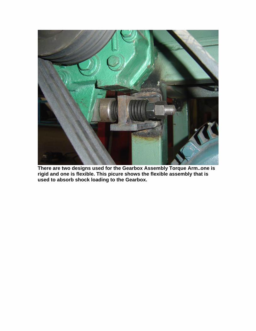
There are two designs used for the Gearbox Assembly Torque Arm..one is rigid and one is flexible. This picure shows the flexible assembly that is used to absorb shock loading to the Gearbox.

This is the fill level port on the Gearbox. Gearbox fluid is put in the top of the gearbox. Normal procedure is to remove this plug and full the Gearbox until fluid flows from this port. Then the plug is placed back and tightened.

This picture shows the safety shutoff knob for emergency shutoff of the unit and the door limit switch that prevents the door from not being bolted in place prior to startup.

The Ram has guide rails that can be replaced when work and are on the top and bottom and both sides of the Ram ( front and back )
This picture shows the back guide rails on the Ram. The Top Back Rails are inverted and accessed by the top cover plate on the unit. The Back Left, Back Right and Bottom Rails are seen and accessed from the back.
4. Installation This data is for your review: After receiving the unit ensure that is properly connected electrically and that all bearings and gearboxes are properly lubricated for startup and daily operation.

General Setup of a Machine on Factory Floor.
5. Startup or Test Run of Machine This data is for your review: There is no special procedure for the machine. Push the start button and place material into the shredder for processing. But it is important to know that all machines have their best operational conditions and feed rate in a single shaft grinder and even in a slow speed shear shredder and it is important to obtain optimum throughput rate by adjusting and controlling a number of machine factors.. If you overfeed a single shaft grinder much like a shear shredder then it backs off on the material and you lose time and production. Care should be taken to determine the best conditions for grinding and shredding.
6. Operating and Service and Maintenance This data is for your review: General Service of the Unit should be done daily.

This is a simple machine and due to that fact the only main items to service daily are the bearings and the gearboxes or hydraulic power units and drive motors. Proper lubrication and maintenance schedules should be maintained and monitored. This is a very heavy machine and the parts and components are also very heavy and care should be taken to use qualified riggers and maintenance personnel familiar with machinery so that you do not put anyone in danger due to their inexperience. To perform a removal of the Shaft or the Unit it is normally pulled out rom the front or pulled from the Gearbox end of the unit. This is a major factor of our machine design which is always light years ahead of the competition ( because they are always behind in copying our designs ) is the fact that the main shafts can be removed in two ways. One way.
7. Tables of Lubrication Data This data is for your review: Standard Lithium Based Bearing Grease or any high quality Bearing Grease should be used each bearing on both end of each shaft. Zirc Fittings can be found on the bottom or top side of the Bearing Assemblies. The Gearbox Oil for all Internal and External Gearboxes should be chosen for high quality and one recommendation is to use a Chevron NL 220 Gear Compound for Internal Gearboxes. Synthetic Oil is highly recommended for reducing wear. Hydraulic Oil for all hydraulic systems must be at the proper temperature prior to startup. Chevron EP32 is a good hydraulic oil for most applications. Industrial Lubrication Groups should be consulted for their expertise in your local area. However these lubricants have been used for the last 30 years and appear to work well regardless of “ expert “ suggestions.

8. Electrical System This data is for your review for the L Panel Design:
This panel shot shows the improved dust cover for the unit and the additional Auto and Manual Operation Selector Switch on the bottom right of the panel. If the Ram is to be used in the Standard Mode where it moves in a full forward and full reverse direction and is only controlled by the flow needle valve of the hydraulic system for speed of the ram with the stopping of this movement only actuated by the amperage of the unit then you need to move the selector switch to the left position. If you want the unit to be in a Patented Mode of Jogging where the ram moves forward for a preset time and then pauses for a preset time with the speed of the Ram as it moves in the forward mode still controlled by the needle valve on the hydraulic system but is assisted with a jogging mode timed pause as it moves forward then you move the selector switch to the right position.

This is a view of a standard electrical control setup when shipped to your group. In some cases the electrical panel is shipped loose but in most cases is has been setup and hooked up to the system components to reduce the cost to your group for electrical installation. Bring Into the panel the main power wires and you are ready to startup the unit ( after adding gearbox and hydraulic fluid to the unit )

This is a typical shot of the panel top row of components. On the Left is the Circuit Breaker, The Motor Starter for the Hydraulic Pump, the two Main Control Relay Groups, the Power Transformer and the PLC Card.

This shows the PLC Main Card on the Right and the small PLC Card on the left of the green card.
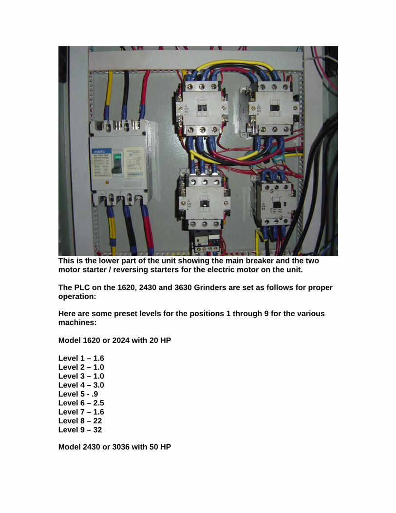
This is the lower part of the unit showing the main breaker and the two motor starter / reversing starters for the electric motor on the unit. The PLC on the 1620, 2430 and 3630 Grinders are set as follows for proper operation: Here are some preset levels for the positions 1 through 9 for the various machines: Model 1620 or 2024 with 20 HP Level 1 – 1.6 Level 2 – 1.0 Level 3 – 1.0 Level 4 – 3.0 Level 5 - .9 Level 6 – 2.5 Level 7 – 1.6 Level 8 – 22 Level 9 – 32 Model 2430 or 3036 with 50 HP

Level 1 – 2.5 Level 2 – 1.0 Level 3 – 1.0 Level 4 – 3.1 Level 5 - .8 Level 6 – 2.5 Level 7 – 3.0 Level 8 – 65 Level 9 – 100
This is a shot of the PLC front panel where you can set or change the main settings of the unit for automatic operation and control. By Pressing the Two Set Buttons at the same time the functions can be changed by pressing the Up or Down Arrows to select the Setting ( Normally 1 through 9 ) shown on the first digit of the LED readout. The Settings which are normally Amperage or Time Settings are read on the last three digits of the LED readout. To Set the PLC on the Upper Right Corner of the Electrical Panel Face you press and hold the two SET buttons on the Key Pad and release them and you will see on the left of the screen a number which varies from 1 to 9, you can use the up and down arrows on the Keypad of the PLC to get to these

numbers. Once you have selected the number ( 1 thru 9 ) you can use the up and down arrows on the Keypad to set the proper settings which is shown in the middle of the LED screen on the PLC Panel and shows XXX.X for setting selection, so ensure that if you want the number one that you have it show 1.0 and not just .1. The Number One Setting ( 1 of the 1 thru 9 Settings ) is used to set the Spike Delay when the motor starts up and this is normally set to 3 or 4 on the panel. A Setting of 2 to 4 can also be used in lower horsepower models The Number Two Setting ( 2 of the 1 thru 9 Settings ) is used to set the Forward Delay of the Electric Motor and is normally set to 3 or 4 on the panel. A Setting of 2 to 4 can also be used in lower horsepower models The Number Three Setting ( 3 of the 1 thru 9 Settings ) is used to set the spike delay for the 80% of Full Load Amperage setting which is normally set to .3 for proper activation. In higher horsepower units this setting can be as high as 1.5 to 2 due to larger spiking ranges in the larger horsepower units. The Number Four Setting ( 4 of the 1 thru 9 Settings ) is used to set the Back Time for the Ram which depends on the Main Relief Pressure Setting and the Flow Restrictor Setting but can be initially set at .8 for a starting point. Settings of 1 to 1.5 are sometimes more effective. The Number Five Setting ( 5 of the 1 thru 9 Settings ) is used to set the 120% Full Load Timers which is normally set at 2.5 to 5 for best actuation. In larger horsepower situations a setting of 2 to 4 is often better for actuation. The Number Six Setting ( 6 of the 1 thru 9 Settings ) is used to Set the Forward Stop Time for the Electric Motor for the Reversal Sequence and is normally set at 1.5 for small motors under 30 HP and 3.0 for 30 HP or larger motors. Mid Range Settings for smaller motors and larger motors lower than those listed for this setting can be used. The Number Seven Setting ( 7 of the 1 thru 9 Settings ) is used to Set the Reversal Stop Time for the Electric Motor for the Reversal Sequence and is normally set at 1.5 for small motors under 30 Hp and 3.0 for 30 Hp or larger motors. Mid Range Settings for smaller motors and larger motors lower than those listed for this setting can be used. The Number Eight Setting ( 8 of the 1 thru 9 Setting ) is used to set the 80% full load Amp Setting which is 24 for the 20 Hp Motor, 46 for the 40 Hp Motor and 61 for the 50 Hp Motor . These settings sometimes depend on

the materials and a number of other factors but should be within ranges for effective grinding. The Number Nine Setting ( 9 of the 1 thru 9 Setting ) is used to set the 120% full load Amp Setting which is 35 for the 20 Hp Motor, 60 for the 40 Hp Motor, and 80 for the 50 Hp Motor. These settings sometimes depend on the materials and a number of other factors but should be within ranges for effective grinding. When this is done the PLC will return to a standard LED display after about 30 seconds of inactivity after you have made these settings. If you have any questions please contact our office. Sincerely, ____________________________Dan Burda, President Global Development All Copyright, Trademark and Patent Rights Reserved 1966-2004, Proprietary and Confidential Data of Dan Burda, Restricted Use Notification., Attorney Client Privilege. As part of our continuing design and engineering program, we reserves the right to make changes at any time in materials, models, specifications and prices without prior, written notice or obligation. All Equipment is offered subject to prior sale or disposition and written confirmation prior to acceptance of offer from Buyer. All Orders and Services are accepted only according to a Liability Release, General Terms and Conditions Policy, provided with all orders, additional copies available upon request. Scanning of our computer systems are not authorized and is considered a violation of our constitutional and legal rights. Original Owner and Inventor of the Saturn Shredder and SSI International Shredder Lines. Secondary Owner/Supplier of Eidal Vertical and Shear Shredder Lines, Duerr Wood Chipper, Tool Barn Wood Chipper, Techwood Wood Chipper, Cougar Wood Chipper and Machete Wood Chipper Lines. Engineering, Parts and Service for all waste processing type shredding and processing equipment.
Worldwide Manufacturing and Consultation, Turnkey Manufacturing Systems, Industrial Equipment, Environmental and Recycling Equipment, OEM/OE Production Systems and Parts, Contract Engineering Design and Consultation, Domestic and Worldwide Sales and Marketing Services, Domestic and International OEM/OE Manufacturing Services, Import and Export Consultation and Coordination Services, and Strategic Planning, Appraisal Services, Equipment Location Services, Acquisition and Liquidation Services, Product Liability Evaluation Services, Product Design Evaluation Services.
The statements included in this data concerning predictions of economic performance and management's plans and objectives constitute forward- looking statements made pursuant to the safe harbor provisions of Section 21E of the Securities Exchange Act of 1934, as amended, and Section 27A of the Securities Act of 1934, as amended. These statements involve risks and uncertainties that could cause actual results to differ materially from the forward-looking statements. Factors which could cause or contribute to such differences include, but are not limited to, factors detailed in the Securities and Exchange Commission filings of the company, economic downturns affecting the operations of the company or any of its business operations, the continued availability of financing to fund the company's operations, and the ability of the company or its investment banker to successfully identify and reach an agreement on the sale of the company or its operating units. The forward-looking statements contained in this press release speak only as of the date hereof and the company disclaims any intent or obligation to update these forward-looking statements.

9. Drawings This data is for your review: General Layout Drawing General Foot Pad Drawing General Electrical Drawing General Electrical Panel Parts Drawing See the Drawings attached. Sincerely, ____________________________Dan Burda, President Global Development All Copyright, Trademark and Patent Rights Reserved 1966-2004, Proprietary and Confidential Data of Dan Burda, Restricted Use Notification., Attorney Client Privilege. As part of our continuing design and engineering program, we reserves the right to make changes at any time in materials, models, specifications and prices without prior, written notice or obligation. All Equipment is offered subject to prior sale or disposition and written confirmation prior to acceptance of offer from Buyer. All Orders and Services are accepted only according to a Liability Release, General Terms and Conditions Policy, provided with all orders, additional copies available upon request. Scanning of our computer systems are not authorized and is considered a violation of our constitutional and legal rights. Original Owner and Inventor of the Saturn Shredder and SSI International Shredder Lines. Secondary Owner/Supplier of Eidal Vertical and Shear Shredder Lines, Duerr Wood Chipper, Tool Barn Wood Chipper, Techwood Wood Chipper, Cougar Wood Chipper and Machete Wood Chipper Lines. Engineering, Parts and Service for all waste processing type shredding and processing equipment.
Worldwide Manufacturing and Consultation, Turnkey Manufacturing Systems, Industrial Equipment, Environmental and Recycling Equipment, OEM/OE Production Systems and Parts, Contract Engineering Design and Consultation, Domestic and Worldwide Sales and Marketing Services, Domestic and International OEM/OE Manufacturing Services, Import and Export Consultation and Coordination Services, and Strategic Planning, Appraisal Services, Equipment Location Services, Acquisition and Liquidation Services, Product Liability Evaluation Services, Product Design Evaluation Services.
The statements included in this data concerning predictions of economic performance and management's plans and objectives constitute forward- looking statements made pursuant to the safe harbor provisions of Section 21E of the Securities Exchange Act of 1934, as amended, and Section 27A of the Securities Act of 1934, as amended. These statements involve risks and uncertainties that could cause actual results to differ materially from the forward-looking statements. Factors which could cause or contribute to such differences include, but are not limited to, factors detailed in the Securities and Exchange Commission filings of the company, economic downturns affecting the operations of the company or any of its business operations, the continued availability of financing to fund the company's operations, and the ability of the company or its investment banker to successfully identify and reach an agreement on the sale of the company or its operating units. The forward-looking statements contained in this press release speak only as of the date hereof and the company disclaims any intent or obligation to update these forward-looking statements.
This data, and its associated originals, copies, faxes and emails and any files transmitted with it are confidential and intended solely for the use of the individual or entity to which they are addressed. If you are not the intended recipient, you are hereby notified that any dissemination of this communication is prohibited. Please note that any views or opinions presented in this email are solely those of the author and may not necessarily represent those of the company. Although this data has been scanned with a state-of-the-art antivirus scanner, the recipient should check this information and any attachments for the presence of viruses. The company accepts no liability for any damage caused by any virus transmitted by this data via any method of delivery.