global interface commandsonthe cisco ios xr … · global interface commandsonthe cisco ios xr...
TRANSCRIPT

Global Interface Commandsonthe Cisco IOS XRSoftware
This module describes the global command line interface (CLI) commands for configuring interfaces on theCisco CRS Router.
• bandwidth (global), page 2
• clear interface, page 4
• dampening, page 6
• interface (global), page 8
• mtu, page 10
• show im dampening, page 13
• show interfaces, page 17
• shutdown (global), page 28
Cisco IOS XR Interface and Hardware Component Command Reference for the Cisco CRS Router OL-24769-01 1

bandwidth (global)To configure the bandwidth of an interface, use the bandwidth command in interface configuration mode.
bandwidth rate
Syntax Description Amount of bandwidth to be allocated on the interface, in Kilobits per second (kbps).Range is from 0 through 4294967295.
rate
Command Default The default bandwidth depends on the interface type.
Command Modes Interface configuration
Command History ModificationRelease
This command was introduced.Release 2.0
Usage Guidelines
To obtain the default bandwidth for a specific interface, use the show interfaces command after you firstbring up the interface. The default interface bandwidth is displayed in the show interfaces commandoutput.
Note
Task ID OperationsTask ID
executeinterface
read, writebasic-services
Examples This example shows how to configure the bandwidth on a Ten Gigabit Ethernet interface:
RP/0/RP0/CPU0:router# configureRP/0/RP0/CPU0:router# interface TenGigE 0/4/1/0RP/0/RP0/CPU0:router# bandwidth 4000000
Cisco IOS XR Interface and Hardware Component Command Reference for the Cisco CRS Router2 OL-24769-01
Global Interface Commandsonthe Cisco IOS XR Softwarebandwidth (global)

Related Commands DescriptionCommand
Configures an interface or creates or configures a virtualinterface.
interface (global), on page 8
Disables an interface (forces an interface to be administrativelydown).
shutdown (global), on page 28
Cisco IOS XR Interface and Hardware Component Command Reference for the Cisco CRS Router OL-24769-01 3
Global Interface Commandsonthe Cisco IOS XR Softwarebandwidth (global)

clear interfaceTo clear interface statistics or packet counters, use the clear interface command in EXEC mode.
clear interface type interface-path-id
Syntax Description Interface type. For more information, use the question mark (?) online help function.type
Physical interface or virtual interface.
Use the show interfaces command to see a list of all interfaces currentlyconfigured on the router.
Note
For more information about the syntax for the router, use the question mark (?) onlinehelp function.
interface-path-id
Command Default No default behavior or values
Command Modes EXEC
Command History ModificationRelease
This command was introduced.Release 2.0
Usage Guidelines For the interface-path-id argument, use these guidelines:
• If specifying a physical interface, the naming notation is rack/slot/module/port. The slash between valuesis required as part of the notation. An explanation of each component of the naming notation is as follows:
◦rack: Chassis number of the rack.
◦slot: Physical slot number of the line card.
◦module: Module number. A physical layer interface module (PLIM) is always 0.
◦port: Physical port number of the interface.
• If specifying a virtual interface, the number range varies, depending on interface type.
Task ID OperationsTask ID
executeinterface
Cisco IOS XR Interface and Hardware Component Command Reference for the Cisco CRS Router4 OL-24769-01
Global Interface Commandsonthe Cisco IOS XR Softwareclear interface
OperationsTask ID
read, writebasic-services
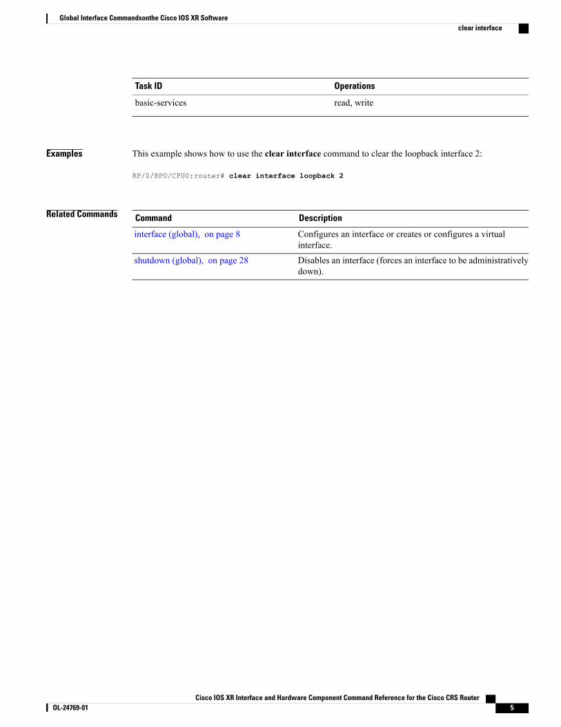
Examples This example shows how to use the clear interface command to clear the loopback interface 2:
RP/0/RP0/CPU0:router# clear interface loopback 2
Related Commands DescriptionCommand
Configures an interface or creates or configures a virtualinterface.
interface (global), on page 8
Disables an interface (forces an interface to be administrativelydown).
shutdown (global), on page 28
Cisco IOS XR Interface and Hardware Component Command Reference for the Cisco CRS Router OL-24769-01 5
Global Interface Commandsonthe Cisco IOS XR Softwareclear interface

dampeningTo limit propagation of transient or frequently changing interface states on Interface Manager (IM) clients,turn on event dampening by using the dampening command in interface configurationmode. To turn dampeningoff, use the no form of this command.
dampening [half-life [reuse suppress max-suppress-time]]
no dampening [half-life [reuse suppress max-suppress-time]]
Syntax Description (Optional) Time (in minutes) after which a penalty is decreased. Once the interface hasbeen assigned a penalty, the penalty is decreased by half after the half-life period. Theprocess of reducing the penalty happens every 5 seconds. The range of the half-lifeperiod is 1 to 45 minutes. The default is 1 minute.
half-life
(Optional) Penalty value belowwhich a stable interface is unsuppressed. Range is from1 through 20000. Default value is 750.
reuse
(Optional) Limit at which an interface is suppressed when its penalty exceeds that limit.Range is from 1 through 20000, and must be greater than the reuse threshold. Thedefault value is 2000.
suppress
(Optional) Maximum time (in minutes) that an interface can be suppressed. This valueeffectively acts as a ceiling that the penalty value cannot exceed. Default value is fourtimes the half-life period.
max-suppress-time
Command Default Dampening is turned off by default. When you use the dampening command, the following default valuesare enabled for any optional parameters that you do not enter:
• half-life: 1 minute
• reuse: 750
• suppress: 2000
• max-suppress-time: Four times the half-life
Command Modes Interface configuration
Command History ModificationRelease
This command was introduced.Release 2.0
Cisco IOS XR Interface and Hardware Component Command Reference for the Cisco CRS Router6 OL-24769-01
Global Interface Commandsonthe Cisco IOS XR Softwaredampening

Usage Guidelines Event dampening suppresses a constantly unstable interface until it remains stable for a period of time. Enablingdampening on an interface that already has dampening configured has the effect of resetting the penaltyassociated with that interface to zero. The reuse threshold must always be less than the suppress threshold.
Consider the following guidelines when configuring event dampening:
• Configuring dampening on both a subinterface and its parent is usually unnecessary because their statesare almost always the same and dampening would be triggered at the same time on each interface.
• If all subinterfaces require dampening, then apply dampening to the main interface only. Applyingconfiguration to large numbers of subinterfaces requires an abundance of memory and increases thetime required to process the configuration during boot and failover.
• When dampening is enabled, an interface has a penalty value associated with it. The value starts at 0and is increased by 1000 whenever the underlying state of the interface changes from up to down.
• The penalty value decreases exponentially while the interface state is stable. If the penalty value exceedsa configured suppress threshold, then the state of the interface is suppressed and IMwill not notify upperlayers of further state transitions. The suppressed state remains until the penalty value decreases past aconfigured reuse threshold.
Task ID OperationsTask ID
read, writeinterface
Examples This example shows how to enable dampening with default values on an interface:
RP/0/RP0/CPU0:router(config)# interface TenGigE 0/4/0/0RP/0/RP0/CPU0:router(config-if))# dampening
Related Commands DescriptionCommand
Displays the state of all interfaces on which dampening has beenconfigured.
show im dampening, on page 13
Cisco IOS XR Interface and Hardware Component Command Reference for the Cisco CRS Router OL-24769-01 7
Global Interface Commandsonthe Cisco IOS XR Softwaredampening

interface (global)To configure an interface or to create or configure a virtual interface, use the interface command in globalconfiguration mode. To delete the interface configuration, use the no form of this command.
interface type interface-path-id
no interface type interface-path-id
Syntax Description Interface type. For more information, use the question mark (?) online help function.type
Physical interface or virtual interface.
Use the show interfaces command to see a list of all interfaces currentlyconfigured on the router.
Note
For more information about the syntax for the router, use the question mark (?) onlinehelp function.
interface-path-id
Command Default No interfaces are configured
Command Modes Global configuration
Command History ModificationRelease
This command was introduced.Release 2.0
Usage Guidelines For the interface-path-id argument, use the following guidelines:
• If specifying a physical interface, the naming notation is rack/slot/module/port. The slash between valuesis required as part of the notation. An explanation of each component of the naming notation is as follows:
◦rack: Chassis number of the rack.
◦slot: Physical slot number of the line card.
◦module: Module number. A physical layer interface module (PLIM) is always 0.
◦port: Physical port number of the interface.
• If specifying a virtual interface, the number range varies, depending on interface type.
The interface command enters interface configuration mode to allow you to configure interfaces. If a virtualinterface is configured, then the interface is created if it did not already exist.
Cisco IOS XR Interface and Hardware Component Command Reference for the Cisco CRS Router8 OL-24769-01
Global Interface Commandsonthe Cisco IOS XR Softwareinterface (global)

The no form of this command applies only to virtual interfaces or to subinterfaces (that is, interfaces that havebeen created in global configuration mode).
Task ID OperationsTask ID
read, writeinterface
Examples In the following example, the interface command is given for the POS card in location 0/2/0/1, and interfaceconfiguration mode is entered for that interface:
RP/0/RP0/CPU0:router(config)# interface POS 0/2/0/1
Related Commands DescriptionCommand
Clears interface statistics or packet counters.clear interface, on page 4
Disables an interface (forces an interface to be administrativelydown).
shutdown (global), on page 28
Cisco IOS XR Interface and Hardware Component Command Reference for the Cisco CRS Router OL-24769-01 9
Global Interface Commandsonthe Cisco IOS XR Softwareinterface (global)

mtuTo adjust the maximum transmission unit (MTU) value for packets on the interface, use themtu commandin interface configuration mode. To return the interface to the default MTU for the interface type, use the noform of this command.
mtu bytes
no mtu
Syntax Description Maximum number of bytes in a Layer 2 frame. Range is from 64 through 65535.bytes
Command Default The default MTU for each interface is as follows:
• Ethernet—1514 bytes
• POS—4474 bytes
• Tunnel—1500 bytes
• Loopback—1514 bytes
• ATM—4470 bytes
Command Modes Interface configuration
Command History ModificationRelease
This command was introduced.Release 2.0
Usage Guidelines Use themtu command to set a specific MTU value for an interface, or use the no mtu command to returnthe interface to the default MTU value for that interface type. The MTU value can be increased or decreasedusing themtu command, subject to minimum and maximum MTU limits for the interface type.
If the MTU value is not configured, then each interface will have a default MTU value that is specific to theinterface type. The default MTU value is generally the largest Layer 2 frame size possible for the interfacetype.
The default/configured MTU value on an atm interface includes the L2 header.
The MTU size consists of L2 header that includes either SNAP(8bytes)/MUX(0)/NLPID(2) header or theAAL5 SDU. The AAL5 SDU includes the L3 datagram and the optional Logical Link Control/SubnetworkAccess Protocol (LLC/SNAP) header.
The Ethernet interface is the Layer 3 datagram plus 14 bytes. For ATMmain interface, theMTU is L3 datagram+ 0 bytes.
Cisco IOS XR Interface and Hardware Component Command Reference for the Cisco CRS Router10 OL-24769-01
Global Interface Commandsonthe Cisco IOS XR Softwaremtu

For ATM L3 sub interface, mtu is as follows:
• SNAP - L3 datagram + 8 bytes
• NLPID - L3 datagram + 2 bytes
• MUX - L3datagram + 0 bytes
• When no pvc is configured under sub interface - L3datagram + 0 bytes
All serial links in a Multilink Point-to-Point Protocol (MLPPP) bundle or a Multilink Frame Relay (MFR)bundle inherit the default MTU value from themultilink bundle. If a serial interface has a nondefault MTUvalue, the Cisco IOS XR software blocks that serial interface from being added to an MLPPP or MFRbundle. Therefore, you must not configure the MTU value on a serial interface until you have added thatserial interface to an MLPPP or MFR bundle.
Note
You can use the show interfaces command to determine if the MTU value has been changed. The showinterfaces command output displays the MTU size for each interface in the MTU (byte) field.
You can use the show interfaces command to determine if the MTU value has been changed. The showinterfaces command output displays the MTU size for each interface in the MTU (byte) field. Note thatthe MTU size that is displayed includes the Layer 2 header bytes used for each encapsulation type.
Note
Changing the MTU on an interface triggers a change on the protocols and capsulations configured on thatinterface, although some protocol-specific configurations can override the interface MTU. For example,specifically changing the interfaceMTU configuration does not affect the IPMTU configuration, but mayaffect the resulting MTU on that node.
Note
Task ID OperationsTask ID
read, writeinterface
Examples In the following example, the MTU value for all interfaces is verified. The MTU value is shown in thenext-to-last column:
RP/0/RP0/CPU0:router# show interfaces all brief
Intf Intf LineP Encap MTU BWName State State Type (byte) (Kbps)
--------------------------------------------------------------------------------Nu0 up up Null 1500 Unknown
TenGigE6/0/0/0 up up HDLC 4474 2488320TenGigE6/0/0/1 up up HDLC 4474 2488320TenGigE6/0/0/2 admin-down admin-down HDLC 4474 2488320TenGigE6/0/0/3 admin-down admin-down HDLC 4474 2488320
Mg0/RP0/CPU0/0 up up ARPA 1514 100000
Cisco IOS XR Interface and Hardware Component Command Reference for the Cisco CRS Router OL-24769-01 11
Global Interface Commandsonthe Cisco IOS XR Softwaremtu

RP/0/RP0/CPU0:router# configureRP/0/RP0/CPU0:router(config)# interface TenGigE 6/0/0/0RP/0/RP0/CPU0:router(config-if)# mtu 1000
After themtu command is used to decrease the MTU Layer 2 frame size for the POS interface on 6/0/0/0 to1000 bytes, the show interfaces all brief command is used again to verify that the MTU Layer 2 frame sizehas been changed:
RP/0/RP0/CPU0:router# show interfaces all brief
Intf Intf LineP Encap MTU BWName State State Type (byte) (Kbps)
--------------------------------------------------------------------------------Nu0 up up Null 1500 Unknown
PO6/0/0/0 up up HDLC 1000 2488320PO6/0/0/1 up up HDLC 4474 2488320PO6/0/0/2 admin-down admin-down HDLC 4474 2488320PO6/0/0/3 admin-down admin-down HDLC 4474 2488320
Mg0/RP0/CPU0/0 up up ARPA 1514 100000
Related Commands DescriptionCommand
Disables an interface (forces an interface to be administrativelydown).
shutdown (global), on page 28
Cisco IOS XR Interface and Hardware Component Command Reference for the Cisco CRS Router12 OL-24769-01
Global Interface Commandsonthe Cisco IOS XR Softwaremtu

show im dampeningTo display the state of all interfaces on which dampening has been configured, use the show im dampeningcommand in EXEC mode.
show im dampening [interface type| ifhandle handle]
Syntax Description (Optional) Interface type. For more information, use the question mark (?)online help function.
interface type
(Optional) Identifies the caps node whose InterfaceManager (IM) dampeninginformation you want to display.
ifhandle handle
Command Default If you do not specify an interface, then the system displays brief details about all dampened interfaces.
Command Modes EXEC
Command History ModificationRelease
This command was introduced.Release 2.0
Usage Guidelines If you do not specify an interface, then the system displays brief details about all dampened interfaces.
The physical hardware (layer 1) is not the only part of an interface that can change state. L2 keepalive failureevent is one of the many instances that can have a similar impact on routing protocols despite the underlyinginterface state staying UP. To take account of such events, when dampening is configured on an interface, itis applied independently to every layer. They all use the same parameters as the interface but they have theirown penalty value which is incremented when that layer changes state.
Capsulations that may be dampened in this way include these:
• L2 basecaps, such as HDLC and PPP, which may flap if keepalives are not received due to events suchas intermittent packet loss.
• L3 capsulations (for example ipv4, ipv6). These may be brought down if another link has a conflictingIP address configured.
• Other locations where negotiation takes place with a peer router, as in the case of PPP control protocolssuch as IPCP. If the negotiation fails, then the caps is brought down.
Cisco IOS XR Interface and Hardware Component Command Reference for the Cisco CRS Router OL-24769-01 13
Global Interface Commandsonthe Cisco IOS XR Softwareshow im dampening

Task ID OperationsTask ID
readinterface
Examples This example shows the output from the show im dampening command issued with default values:
RP/0/RP0/CPU0:router(config)# interface TenGigE 0/4/0/0RP/0/RP0/CPU0:router(config-if)# no shutdownRP/0/RP0/CPU0:router(config-if)# dampeningRP/0/RP0/CPU0:router# show im dampening
Interface Proto Caps Penalty Suppressed
--------- ----- ---- ----------------TenGigE0/4/0/0 0 0 0 NO
RP/0/RP0/CPU0:router# show im dampening interface TenGigE 0/4/0/0
TenGigE0/4/0/0 (0x05000d00)Dampening enabled: penalty 0, not suppressedunderlying state: Uphalf_life: 1 reuse: 750suppress: 3000 max-suppress-time: 4restart-penalty: 0
RP/0/RP0/CPU0:router# show interfaces TenGigE 0/4/0/0
TenGigE0/4/0/0 is up, line protocol is downDampening enabled: penalty 0, not suppressedhalf_life: 1 reuse: 750suppress: 3000 max-suppress-time: 4restart-penalty: 0
Hardware is Ten Gigabit EthernetDescription: ensoft-gsr5 TenGigE 4\2Internet address is UnknownMTU 4474 bytes, BW 155520 Kbit
reliability 255/255, txload 1/255, rxload 1/255Encapsulation HDLC, crc 16, controller loopback not set, keepalive set (10 sec)Last clearing of "show interface" counters never30 second input rate 0 bits/sec, 0 packets/sec30 second output rate 0 bits/sec, 0 packets/sec
0 packets input, 0 bytes, 0 total input drops0 drops for unrecognized upper-level protocolReceived 0 broadcast packets, 0 multicast packets
0 runts, 0 giants, 0 throttles, 0 parity0 input errors, 0 CRC, 0 frame, 0 overrun, 0 ignored, 0 abort48 packets output, 1504 bytes, 0 total output dropsOutput 0 broadcast packets, 0 multicast packets0 output errors, 0 underruns, 0 applique, 0 resets0 output buffer failures, 0 output buffers swapped out
This sample output shows a POS interface with PPP basecaps and IPCP. The subsequent output for show imdampening interface <ifname> contains a table of any capsulations which have their own penalty as shownbelow:
RP/0/RP0/CPU0:router# show im dampening
Interface Protocol Capsulation Pen Sup--------------------------- ------------------ -------------------- ----- ---GigabitEthernet0/0/0/0 629 NO
Cisco IOS XR Interface and Hardware Component Command Reference for the Cisco CRS Router14 OL-24769-01
Global Interface Commandsonthe Cisco IOS XR Softwareshow im dampening

GigabitEthernet0/0/0/1 2389 YESPOS0/2/0/0 0 NOPOS0/2/0/0 <base> ppp 0 NOPOS0/2/0/0 ipv4 ipcp 0 NO
RP/0/RP0/CPU0:router# show im dampening interface TenGigaE 0/1/0/0
TenGigE 0/1/0/0 (0x01180020)Dampening enabled: Penalty 1625, SUPPRESSED (42 secs remaining)Underlying state: Downhalf-life: 1 reuse: 1000suppress: 1500 max-suppress-time: 4restart-penalty: 0
Protocol Capsulation Pen Suppression U-L State-------------- ------------------ ----- --------------------- -------------ipv6 ipv6 1625 YES 42s remaining Down
When dampening is configured on an interface it is also applied independently to all capsulations on thatinterface. For example, the ppp or hdlc basecaps state can flap even while the interface stays up and ifkeepalives fail. The show im dampening interface command contains one line for each such capsulationas well as the interface itself.
Note
Table 1: show im dampening Field Descriptions
DescriptionField
Indicates the dampening state and penalty value: notsuppressed, suppressed.
Dampening
Underlying state of the interface: up, down,administratively down (if an interface has beenconfigured to be “shutdown”).
underlying state
This is the time (in minutes) at which the penalty onthe interface would be half that of the original penalty(of 1000) when the interface transitions from UP toDOWN. It ranges from 1 to 45minutes and the defaultis 1 minute.
half_life
Penalty value below which a stable interface isunsuppressed. It ranges from 1 to 20000 and thedefault value is 750.
reuse
Limit at which an unstable interface is suppressedwhen the penalty value exceeds the suppress value.It ranges from 1 to 20000 and the default value is2000.
suppress
Maximum time (in minutes) that an interface can besuppressed. The default is 4 minutes.
max-suppress-time
Penalty assigned to the interface when it flaps.restart-penalty
Cisco IOS XR Interface and Hardware Component Command Reference for the Cisco CRS Router OL-24769-01 15
Global Interface Commandsonthe Cisco IOS XR Softwareshow im dampening

Related Commands DescriptionCommand
Turns on event dampening.dampening, on page 6
Disables an interface (forces an interface to beadministratively down).
shutdown (global), on page 28
Cisco IOS XR Interface and Hardware Component Command Reference for the Cisco CRS Router16 OL-24769-01
Global Interface Commandsonthe Cisco IOS XR Softwareshow im dampening

show interfacesTo display statistics for all interfaces configured on the router or for a specific node, use the show interfacescommand in EXEC mode.
show interfaces [type interface-path-id| all| local| location node-id] [accounting| brief| description| detail|summary]
Syntax Description (Optional) Specifies the type ofinterface for which you want todisplay statistics. For moreinformation, use the question mark(?) online help function.
type
Physical interface or virtualinterface.
Use the show interfacescommand to see a list ofall interfaces currentlyconfigured on the router.
Note
For more information about thesyntax for the router, use thequestion mark (?) online helpfunction.
interface-path-id
(Optional) Displays interfaceinformation for all interfaces .Thisis the default.
all
(Optional) Displays interfaceinformation for all interfaces in thelocal card.
local
(Optional) Displays informationabout all interfaces on the specifiednode. The node-id argument isentered in the rack/slot/modulenotation.
location node-id
(Optional) Displays the number ofpackets of each protocol type thathave been sent through theinterface.
accounting
(Optional) Displays briefinformation of each interface (oneline per interface).
brief
Cisco IOS XR Interface and Hardware Component Command Reference for the Cisco CRS Router OL-24769-01 17
Global Interface Commandsonthe Cisco IOS XR Softwareshow interfaces

(Optional) Displays the status,protocol, and description of eachinterface (one line per interface).
description
(Optional) Displays detailedinformation about each interface.This is the default.
detail
(Optional) Displays a summary ofinterface information by interfacetype.
summary
Command Default No default behavior or values
Command Modes EXEC
Command History ModificationRelease
This command was introduced.Release 2.0
The err-disable interface state was added as a possible interface state outputvalue for bundle member links that have been administratively shut down.
Release 3.8.4
Added QoS drops to total input drops and total output drops statistics.Release 4.0.0
Usage Guidelines For the interface-path-id argument, use the following guidelines:
• If specifying a physical interface, the naming notation is rack/slot/module/port. The slash between valuesis required as part of the notation. An explanation of each component of the naming notation is as follows:
◦rack: Chassis number of the rack.
◦slot: Physical slot number of the line card.
◦module: Module number. A physical layer interface module (PLIM) is always 0.
◦port: Physical port number of the interface.
• If specifying a virtual interface, the number range varies, depending on interface type.
The show interfaces command displays statistics for the network interfaces. The resulting display shows theinterface processors in slot order.
For example, if you type the show interfaces command without an interface type, you receive informationfor all the interfaces installed in the networking device. Only by specifying the interface type, slot, and portarguments can you display information for a particular interface.
Cisco IOS XR Interface and Hardware Component Command Reference for the Cisco CRS Router18 OL-24769-01
Global Interface Commandsonthe Cisco IOS XR Softwareshow interfaces

If you enter a show interfaces command for an interface type that has been removed from the networkingdevice, an error message is displayed: “Interface not found.”The output displayed depends on the network for which an interface has been configured.
Beginning in Cisco IOS XR Release 3.8.4, when you shut down a bundle interface, the member links are putinto err-disable link interface status and admin-down line protocol state.
The 5-minute input and output rates should be used only as an approximation of traffic per second duringa given 5-minute period. These rates are exponentially weighted averages with a time constant of 5 minutes.A period of four time constants must pass before the average is within 2 percent of the instantaneous rateof a uniform stream of traffic over that period.
Note
Task ID OperationsTask ID
readinterface
Examples The following example shows the output from the show interfaces command. The output displayed dependson the type and number of interface cards in the networking device.
RP/0/RP0/CPU0:router# show interfaces tenGigE 0/0/0/1
TenGigE0/0/0/1 is administratively down, line protocol is administratively downHardware is TenGigE, address is 0800.4539.d909 (bia 0800.4539.d909)Description: user defined stringInternet address is UnknownMTU 1514 bytes, BW 10000000 Kbit
reliability 255/255, txload 0/255, rxload 0/255Encapsulation ARPA,Full-duplex, 10000Mb/s, LRoutput flow control is off, input flow control is offloopback not setARP type ARPA, ARP timeout 01:00:00Last clearing of "show interface" counters never5 minute input rate 0 bits/sec, 0 packets/sec5 minute output rate 0 bits/sec, 0 packets/sec
0 packets input, 0 bytes, 0 total input drops0 drops for unrecognized upper-level protocolReceived 0 broadcast packets, 0 multicast packets
0 runts, 0 giants, 0 throttles, 0 parity0 input errors, 0 CRC, 0 frame, 0 overrun, 0 ignored, 0 abort0 packets output, 0 bytes, 0 total output dropsOutput 0 broadcast packets, 0 multicast packets0 output errors, 0 underruns, 0 applique, 0 resets0 output buffer failures, 0 output buffers swapped out0 carrier transitions
In the following sample output, instance 1 is specified on a Packet-over-SONET/SDH (POS) card:
RP/0/RP0/CPU0:router# show interfaces POS 0/1/0/1
POS0/1/0/1 is administratively down, line protocol is administratively downHardware is Packet over SONETInternet address is n.n.n.n/nMTU 4474 bytes, BW 9953280 Kbit
reliability 255/255, txload 0/255, rxload 0/255
Cisco IOS XR Interface and Hardware Component Command Reference for the Cisco CRS Router OL-24769-01 19
Global Interface Commandsonthe Cisco IOS XR Softwareshow interfaces

Encapsulation HDLC, crc 32, controller loopback not set, keepalive not setLast clearing of "show interface" counters never5 minute input rate 0 bits/sec, 0 packets/sec5 minute output rate 0 bits/sec, 0 packets/sec
0 packets input, 0 bytes, 0 total input drops0 drops for unrecognized upper-level protocolReceived 0 broadcast packets, 0 multicast packets
0 runts, 0 giants, 0 throttles, 0 parity0 input errors, 0 CRC, 0 frame, 0 overrun, 0 ignored, 0 abort0 packets output, 0 bytes, 0 total output dropsOutput 0 broadcast packets, 0 multicast packets0 output errors, 0 underruns, 0 applique, 0 resets0 output buffer failures, 0 output buffers swapped out
The following example shows sample output for ATM subinterface 0/4/2/0/1.1:
RP/0/RP0/CPU0:router# show interfaces ATM0/4/2/0/1.1
ATM0/4/2/0/1.1 is up, line protocol is upInterface state transitions: 1Hardware is ATM network sub-interface(s)Description: Connected to PE22_C12406 ATM 0/4/0/0/1.1Internet address is 10.212.4.21/24MTU 4486 bytes, BW 1544 Kbit
reliability Unknown, txload Unknown, rxload UnknownEncapsulation AAL5/SNAP, controller loopback not set,Last clearing of "show interface" counters UnknownDatarate information unavailable.Interface counters unavailable.
The show interfaces atm interface-path-id command does not display data rates and counters for an ATMsubinterface. Alternatively, you can use the show interfaces atm interface-path-id accounting commandto view packet and character counters for each protocol, and the show atm pvc vpi/vci command to viewcell, packet, and byte counters.
Note
The following example shows bundle member links whose link interface status is “err-disable” and line protocolstate is “admin-down” after the bundle interface has been administratively shut down using the shutdowncommand:
RP/0/RP0/CPU0:router# show interfaces brief
Thu May 6 06:30:55.797 DST
Intf Intf LineP Encap MTU BWName State State Type (byte) (Kbps)
--------------------------------------------------------------------------------BE16 admin-down admin-down ARPA 9216 1000000
BE16.160 up up 802.1Q VLAN 9220 1000000BE16.161 up up 802.1Q VLAN 9220 1000000BE16.162 up up 802.1Q VLAN 9220 1000000BE16.163 up up 802.1Q VLAN 9220 1000000
Lo0 up up Loopback 1500 UnknownNu0 up up Null 1500 Unknown
tt44190 up up TUNNEL 1500 Unknowntt44192 up up TUNNEL 1500 Unknowntt44194 up up TUNNEL 1500 Unknowntt44196 up up TUNNEL 1500 Unknown
Mg0/RP0/CPU0/0 up up ARPA 1514 100000Mg0/RP0/CPU0/1 admin-down admin-down ARPA 1514 10000
Gi0/1/0/0 admin-down admin-down ARPA 1514 1000000Gi0/1/0/1 admin-down admin-down ARPA 1514 1000000Gi0/1/0/2 up up ARPA 9014 1000000Gi0/1/0/3 up up ARPA 9014 1000000
Gi0/1/0/3.160 up up 802.1Q VLAN 9022 1000000
Cisco IOS XR Interface and Hardware Component Command Reference for the Cisco CRS Router20 OL-24769-01
Global Interface Commandsonthe Cisco IOS XR Softwareshow interfaces

Gi0/1/0/3.161 up up 802.1Q VLAN 9018 1000000Gi0/1/0/3.185 up up 802.1Q VLAN 9022 1000000Gi0/1/0/3.189 up up 802.1Q VLAN 9022 1000000Gi0/1/0/3.215 up up 802.1Q VLAN 9022 1000000
Gi0/1/0/4 admin-down admin-down ARPA 1514 1000000Gi0/1/0/5 admin-down admin-down ARPA 1514 1000000Gi0/1/0/6 admin-down admin-down ARPA 1514 1000000Gi0/1/0/7 up up ARPA 9014 1000000
Gi0/1/0/7.185 up up 802.1Q VLAN 9022 1000000Gi0/1/0/7.187 up up 802.1Q VLAN 9014 1000000Gi0/1/0/7.189 up up 802.1Q VLAN 9022 1000000Gi0/1/0/7.210 up up 802.1Q VLAN 9022 1000000Gi0/1/0/7.211 up up 802.1Q VLAN 9022 1000000Gi0/1/0/7.215 up up 802.1Q VLAN 9022 1000000
Gi0/1/0/8 up up ARPA 9014 1000000Gi0/1/0/9 admin-down admin-down ARPA 1514 1000000Gi0/1/0/10 admin-down admin-down ARPA 1514 1000000Gi0/1/0/11 admin-down admin-down ARPA 1514 1000000Gi0/1/0/12 up up ARPA 9216 1000000Gi0/1/0/13 admin-down admin-down ARPA 1514 1000000Gi0/1/0/14 admin-down admin-down ARPA 1514 1000000Gi0/1/0/15 admin-down admin-down ARPA 1514 1000000Gi0/1/0/16 up up ARPA 9216 1000000Gi0/1/0/17 up up ARPA 1514 1000000Gi0/1/0/18 up up ARPA 9216 1000000Gi0/1/0/19 up up ARPA 9014 1000000
Gi0/1/0/19.2127 up up 802.1Q VLAN 9022 1000000Gi0/1/0/19.2130 up up 802.1Q VLAN 9022 1000000
Gi0/1/0/20 up up ARPA 9014 1000000Gi0/1/0/20.2125 up up 802.1Q VLAN 9022 1000000
Gi0/1/0/21 admin-down admin-down ARPA 1514 1000000Gi0/1/0/22 admin-down admin-down ARPA 1514 1000000Gi0/1/0/23 up up ARPA 9216 1000000Gi0/1/0/24 admin-down admin-down ARPA 1514 1000000Gi0/1/0/25 admin-down admin-down ARPA 1514 1000000Gi0/1/0/26 admin-down admin-down ARPA 1514 1000000Gi0/1/0/27 up up ARPA 1514 1000000Gi0/1/0/28 admin-down admin-down ARPA 1514 1000000Gi0/1/0/29 admin-down admin-down ARPA 1514 1000000Gi0/1/0/30 up up ARPA 9014 1000000
Gi0/1/0/30.215 up up 802.1Q VLAN 9018 1000000Gi0/1/0/31 up up ARPA 9014 1000000Gi0/1/0/32 admin-down admin-down ARPA 1514 1000000Gi0/1/0/33 admin-down admin-down ARPA 1514 1000000Gi0/1/0/34 admin-down admin-down ARPA 1514 1000000Gi0/1/0/35 admin-down admin-down ARPA 1514 1000000Gi0/1/0/36 admin-down admin-down ARPA 1514 1000000Gi0/1/0/37 admin-down admin-down ARPA 1514 1000000Gi0/1/0/38 admin-down admin-down ARPA 1514 1000000Gi0/1/0/39 admin-down admin-down ARPA 1514 1000000Te0/4/0/0 err-disable admin-down ARPA 1514 10000000Te0/4/0/1 err-disable admin-down ARPA 1514 10000000Te0/4/0/2 err-disable admin-down ARPA 1514 10000000Te0/4/0/3 err-disable admin-down ARPA 1514 10000000Te0/4/0/4 err-disable admin-down ARPA 1514 10000000Te0/4/0/5 err-disable admin-down ARPA 1514 10000000Te0/4/0/6 err-disable admin-down ARPA 1514 10000000Te0/4/0/7 err-disable admin-down ARPA 1514 10000000Te0/6/0/0 admin-down admin-down ARPA 1514 10000000Te0/6/0/1 admin-down admin-down ARPA 1514 10000000Te0/6/0/2 admin-down admin-down ARPA 1514 10000000Te0/6/0/3 admin-down admin-down ARPA 1514 10000000
Table 2: show interfaces Field Descriptions
DescriptionField
Displays the name of the current interface. Forexample, TenGigE 0/1/0/1.
Interface name
Cisco IOS XR Interface and Hardware Component Command Reference for the Cisco CRS Router OL-24769-01 21
Global Interface Commandsonthe Cisco IOS XR Softwareshow interfaces

DescriptionField
Displays the state of the interface. For example, theinterface is in the administratively up state.
Interface state
Displays the number of times since the last reloadthat the interface transitioned from theadministratively up state to the administrative downstate and from the administratively down state to theadministratively up state.
Interface state transitions
Displays the state of the Layer 2 line protocol. Thisfield may be different from the interface state if, forexample, a keepalive failure has brought down theLayer 2.
The line protocol state is not the same as theprotocol state displayed in the show ipinterfaces command, because it is the stateof Layer 2 (media) rather than Layer 3 (IPprotocol).
Note
line protocol state
Displays the current hardware type.Hardware
Displays the Layer 2 address (MAC address forEthernet interfaces).
Enter themac-address command toconfigure the hardware address.
Note
Internet address is n.n.n.n/n
Displays the burned-in address (BIA) for the interface.The BIA is the default L2 (MAC) address for theinterface.
The BIA is notconfigurable.
Note
bia
Displays the user-defined string that is associatedwith the interface.
Enter the description command to configurethe description associated with the interface.
Note
description
Displays the Layer 3 (IP) address for the interface.
Enter the ipv4 address command toconfigure the internet address for theinterface.
Note
Internet Address
Displays the maximum transmission unit (MTU) forthe interface. The MTU is the maximum packet sizethat can be transmitted over the interface.
TheMTU field indicates the interfaceMTU.Enter themtu command to configure a lowerMTU value at the Layer 3 level.
Note
MTU
Cisco IOS XR Interface and Hardware Component Command Reference for the Cisco CRS Router22 OL-24769-01
Global Interface Commandsonthe Cisco IOS XR Softwareshow interfaces

DescriptionField
Displays the bandwidth of the interface in kbps.BW
Displays the proportion of packets that are notdropped and do not have errors.
The reliability is shown as a fraction of255.
Note
reliability
Indicates the traffic flowing out of the interface as aproportion of the bandwidth.
The txload is shown as a fraction of255.
Note
txload
Indicates the traffic flowing into the interface as aproportion of the bandwidth.
The rxload is shown as a fraction of255.
Note
rxload
Layer 2 encapsulation installed on the interface.Encapsulation
Indicates the length of the cyclic redundancy check(CRC), in bytes.
The CRC is not present for all interfacetypes.
Note
Enter the pos crc command to configure theCRC.
Note
CRC
Indicates whether the hardware has been configuredto be looped back.
Enter the loopback command to configurethe loopback or controller loopback.
Note
loopback or controller loopback
Displays the configured keepalive value, in seconds.
Enter the keepalive command to configurethe value of the keepalive field.
Note
The keepalive field may not be present if itis not applicable to the interface type.
Note
keepalive
Displays the duplexity of the link.
This field is present only for sharedmedia.
Note
For some interface types, you can configurethe duplexity by entering the full-duplexand half-duplex commands.
Note
Duplexity
Speed and bandwidth of the link in Mbps. This fieldis present only when other parts of the media info lineare also displayed (see duplexity and media type).
Speed
Media type of the interface.Media Type
Cisco IOS XR Interface and Hardware Component Command Reference for the Cisco CRS Router OL-24769-01 23
Global Interface Commandsonthe Cisco IOS XR Softwareshow interfaces

DescriptionField
Whether output flow control is enabled on theinterface.
output flow control
See output flow control.input flow control
Address Resolution Protocol (ARP) type used on theinterface. This value is not displayed on interfacetypes that do not use ARP.
ARP type
ARP timeout in hours:mins:secs. This value isconfigurable using the arp timeout command.
ARP timeout
Time since the following counters were last clearedusing the clear counters exec command inhours:mins:secs.
Last clearing of counters
Average number of bits and packets received persecond in the last 5 minutes. If the interface is not inpromiscuous mode, it senses network traffic that itsends and receives (rather than all network traffic).
The 5-minute period referenced in thecommand output is a load interval that isconfigurable under the interface. The defaultvalue is 5 minutes.
Note
The 5-minute input should be used only asan approximation of traffic per second duringa given 5-minute period. This rate isexponentially weighted average with a timeconstant of 5 minutes. A period of four timeconstants must pass before the average iswithin two percent of the instantaneous rateof a uniform stream of traffic over thatperiod.
Note
5 minute input rate
Cisco IOS XR Interface and Hardware Component Command Reference for the Cisco CRS Router24 OL-24769-01
Global Interface Commandsonthe Cisco IOS XR Softwareshow interfaces

DescriptionField
Average number of bits and packets transmitted persecond in the last 5 minutes. If the interface is not inpromiscuous mode, it senses network traffic that itsends and receives (rather than all network traffic).
The 5-minute period referenced in thecommand output is a load interval that isconfigurable under the interface. The defaultvalue is 5 minutes.
Note
The 5-minute output should be used only asan approximation of traffic per second duringa given 5-minute period. This rate isexponentially weighted average with a timeconstant of 5 minutes. A period of four timeconstants must pass before the average iswithin two percent of the instantaneous rateof a uniform stream of traffic over thatperiod.
Note
5 minute output rate
Number of packets received on the interface that weresuccessfully delivered to higher layers.
packets input
Total number of bytes successfully received on theinterface
bytes input
Total number of packets that were dropped after theywere received. This includes packets that weredropped due to configured quality of service (QoS)or access control list (ACL) policies. QoS dropsinclude policer drops, WRED drops, and tail drops.This does not include drops due to unknown Layer 3protocol.
total input drops
Total number of packets that could not be deliveredbecause the necessary protocol was not configuredon the interface.
drops for unrecognized upper-level protocol
Total number of Layer 2 broadcast packets receivedon the interface. This is a subset of the total inputpacket count.
Received broadcast packets
Total number of Layer 2 multicast packets receivedon the interface. This is a subset of the total inputpacket count.
Received multicast packets
Number of received packets that were too small to behandled. This is a subset of the input errors count.
runts
Number of received packets that were too large to behandled. This is a subset of the input errors count.
giants
Cisco IOS XR Interface and Hardware Component Command Reference for the Cisco CRS Router OL-24769-01 25
Global Interface Commandsonthe Cisco IOS XR Softwareshow interfaces

DescriptionField
Number of packets dropped due to throttling (becausethe input queue was full).
throttles
Number of packets dropped because the parity checkfailed.
parity
Total number of received packets that contain errorsand hence cannot be delivered. Compare this to totalinput drops, which counts packets that were notdelivered despite containing no errors.
input errors
Number of packets that failed the CRC check.CRC
Number of packets with bad framing bytes.frame
Number of overrun errors experienced by theinterface. Overruns represent the number of timesthat the receiver hardware is unable to send receiveddata to a hardware buffer because the input rateexceeds the receiver's ability to handle the data.
overrun
Total number of ignored packet errors. Ignoredpackets are those that are discarded because theinterface hardware does not have enough internalbuffers. Broadcast storms and bursts of noise canresult in an increased number of ignored packets.
ignored
Total number of abort errors on the interface.abort
Number of packets received on the interface that weresuccessfully delivered to higher layers.
packets output
Total number of bytes successfully received on theinterface.
bytes output
Number of packets that were dropped before beingtransmitted. This includes packets that were droppeddue to configured quality of service (QoS), (policerdrops, WRED drops, and tail drops).
total output drops
Number of Layer 2 broadcast packets transmitted onthe interface. This is a subset of the total input packetcount.
Received broadcast packets
Total number of Layer 2multicast packets transmittedon the interface. This is a subset of the total inputpacket count.
Received multicast packets
Cisco IOS XR Interface and Hardware Component Command Reference for the Cisco CRS Router26 OL-24769-01
Global Interface Commandsonthe Cisco IOS XR Softwareshow interfaces

DescriptionField
Number of times that the receiver hardware wasunable to handle received data to a hardware bufferbecause the input rate exceeded the receiver's abilityto handle the data.
output errors
Number of underrun errors experienced by theinterface. Underruns represent the number of timesthat the hardware is unable to transmit data to ahardware buffer because the output rate exceeds thetransmitter’s ability to handle the data.
underruns
Number of applique errors.applique
Number of times that the hardware has been reset.The triggers and effects of this event arehardware-specifc.
resets
Number of times that a packet was not output fromthe output hold queue because of a shortage ofMEMD shared memory.
output buffer failures
Number of packets stored in main memory when theoutput queue is full; swapping buffers to mainmemory prevents packets from being dropped whenoutput is congested. The number is high when trafficis bursty.
output buffers swapped out
Number of times the carrier detect (CD) signal of aserial interface has changed state.
carrier transitions
Related Commands DescriptionCommand
Displays information that is specific to the interfacehardware statistics for all interfaces configured onthe networking device.
show controller interface
Cisco IOS XR Interface and Hardware Component Command Reference for the Cisco CRS Router OL-24769-01 27
Global Interface Commandsonthe Cisco IOS XR Softwareshow interfaces

shutdown (global)To disable an interface (to force an interface to be administratively down), use the shutdown command ininterface configurationmode. To enable an interface that has been shut down, use the no form of this command.
shutdown
no shutdown
Syntax Description This command has no keywords or arguments.
Command Default The interface is enabled by default and is disabled only when shutdown is configured.
When you add an interface to the system, or when all the configuration for an interface is lost or deleted,the interface is put in the shutdown state by the system adding the interface.
Note
Command Modes Interface configuration
Command History ModificationRelease
This command was introduced.Release 2.0
Usage Guidelines Use the shutdown command to move the state of an interface to administratively down, which stops trafficflowing through the interface. This state does not stop other action from happening on the interface such aschanges in configuration, protocols, capsulations, and so forth.
The shutdown command also marks the interface as unavailable. To check whether the state of an interfaceis down, use the show interfaces command in EXEC mode, which displays the current state of the interface.An interface that has been shut down is shown as administratively down in the display from the show interfacescommand.
Task ID OperationsTask ID
read, writeinterface
Examples In this example, TenGigE interface 0/4/0/2 is turned off:
RP/0/RP0/CPU0:router(config)# interface TenGigE 0/4/0/2
Cisco IOS XR Interface and Hardware Component Command Reference for the Cisco CRS Router28 OL-24769-01
Global Interface Commandsonthe Cisco IOS XR Softwareshutdown (global)

RP/0/RP0/CPU0:router(config-if)# shutdown
Related Commands DescriptionCommand
Displays statistics for all interfaces configured on therouter or on a specific node.
show interfaces, on page 17
Displays IPv4 interface status and configuration.show ip interface
Cisco IOS XR Interface and Hardware Component Command Reference for the Cisco CRS Router OL-24769-01 29
Global Interface Commandsonthe Cisco IOS XR Softwareshutdown (global)

Cisco IOS XR Interface and Hardware Component Command Reference for the Cisco CRS Router30 OL-24769-01
Global Interface Commandsonthe Cisco IOS XR Softwareshutdown (global)