global mhd simulations of dayside magnetopause dynamics. themis event: may 20, 2008 20:30 – 22:30
DESCRIPTION
Global MHD Simulations of Dayside Magnetopause Dynamics. THEMIS Event: May 20, 2008 20:30 – 22:30. M. M. Kuznetsova, D. G. Sibeck , M. Hesse , L. Rastaetter , T. Gombosi. http:// ccmc.gsfc.nasa.gov. NASA Goddard Space Flight Center. Global MHD Simulation Model. - PowerPoint PPT PresentationTRANSCRIPT

Global MHD Simulations of Dayside Magnetopause
Dynamics.
THEMIS Event: May 20, 200820:30 – 22:30
NASA Goddard Space Flight Center
M. M. Kuznetsova, D. G. Sibeck, M. Hesse, L. Rastaetter, T. Gombosi
http://ccmc.gsfc.nasa.gov

BATS-R-US (CSEM, University of Michigan) uses an adaptive grid composed of rectangular blocks arranged in varying degrees of spatial refinement levels.
Resolution at Dayside Magnetopause Including Flanks: 1/16 Re
Global MHD Simulation Model
15 – 20 mln grid cells

N = 2 cm –3 , T = 20,000 Ko , Vx = 300 km/s, |B| = 5 nT
Solar Wind Parameters:
IMF Turning From Northward Orientation (θ = 0) to IMF Clock angle θ < 120o:
Runs with Modeled ConditionsKuznetsova et al, 2004
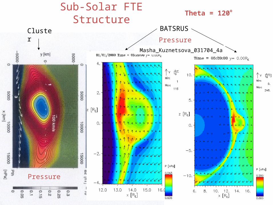
Cluster BATSRUS
Masha_Kuznetsova_031704_4a
Sub-Solar FTE Structure
Theta = 120o
Pressure
Pressure

Vortices Generation at the FlanksClose to regions of large flow velocity shear
and almost anti-parallel magnetic field.Theta = 120o

Vortices at the Flanks for Southward IMF
Joe_Borovsky_040207_1c
Theta = 180o

THEMIS Dayside Event: May 20, 2008, 20:30 – 22:30
Solar wind propagated from ACE to 33 Re
Global Magnetosphere at 22:00
Resolution at Dayside Magnetopause: 1/16 Re

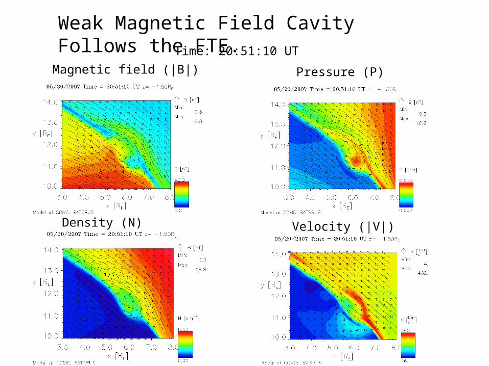
Weak Magnetic Field Cavity Follows the FTE.
Magnetic field (|B|) Pressure (P)
Density (N) Velocity (|V|)
Time: 20:51:10 UT
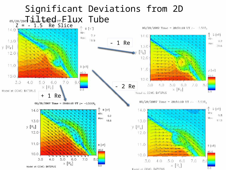
- 1 Re
+ 1 Re
- 2 Re
Z = - 1.5 Re Slice
Significant Deviations from 2D Tilted Flux Tube

Start Points for Field Line Tracing at Z = -1.5 Re Slice
.

View from the South

View from the Sun
Start points for field line tracing atZ = - 1.5 Re slice

Component Reconnection Near Sub-Solar Region (Y ~ 0 – 2 Re)And Anti-Parallel Reconnection at Flanks (Y ~ 12 - 15 Re)

FTE at Flanks (Y = 12 Re) is Connected to FTE at the Sub-Solar Region ( Y = 0 ).
Z-slice
Y-slice
X-slice

Slices Through FTE
Y = 0 Z = - 1.5 |Y - 12| < 2
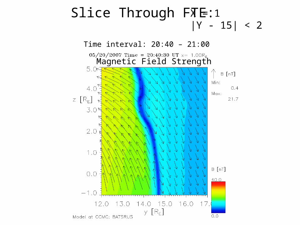
X = 1 |Y – 15| < 2
Magnetic Field Strength
Time: 20:51:10 UT

Slice Through FTE:
Magnetic Field Strength
Y = 0
Time interval: 20:40 – 21:00

FTE Bulge with Strong Core Field
Magnetic field (|B|) Pressure (P)Time: 20:51:10 UT
Density (N) Velocity (|V|)
The plasma pressure exhibit a ring-shaped structure surrounding a central depression
The flow around the flux rope is largest at the magnetosphere side.

Y = 0
+ 2 Re+ 2 Re
Y = 2 ReY = - 2 Re
Signature of Bended Flux Rope (FTE) Near Sub-Solar Region
Bended Flux Rope (FTE) Near Sub-Solar Region

Signature of Bended Flux Rope (FTE)

Signature of Bended Flux Rope
Slice Through FTE:
Magnetic Field Strength
X = 1 |Y - 15| < 2
Time interval: 20:40 – 21:00

Supplementary Slides

Click Here

