global optimization and antennas synthesis …ww.jpier.org/pier/pier56/14.0503253.c.delia.pdf ·...
TRANSCRIPT
Progress In Electromagnetics Research, PIER 56, 233–261, 2006
GLOBAL OPTIMIZATION AND ANTENNASSYNTHESIS AND DIAGNOSIS, PART TWO:APPLICATIONS TO ADVANCED REFLECTORANTENNAS SYNTHESIS AND DIAGNOSISTECHNIQUES
A. Capozzoli and G. D’Elia
Dipartimento di Ingegneria Elettronica e delle TelecomunicazioniUniversita di Napoli “Federico II”Via Claudio, 21, 80125 Napoli, Italia
Abstract—The paper presents the application of the hybrid globaloptimization algorithm, introduced in the companion paper Part I,to reflector antenna power pattern synthesis and reflector antennasurface diagnosis from only amplitude data. The synthesis algorithmdetermines both the reflector surface and the excitation coefficients ofthe array of primary feeds to meet the designing specification on thefar-field pattern expressed by means of two couple of masks boundingthe squared amplitude of both the copolar and crosspolar components.The diagnosis technique allows to find the reflector surface profilefrom the measurement of the far field power pattern by a properformulation of the corresponding inverse problem. In both cases wetake advantage of the exploring capability of an evolutionary algorithmand of the solution refinement capability of an efficient, quasi-Newtonbased, local search procedure. The numerical analysis shows thatGlobal Optimization can outperform the standard local approach, bysignificantly improving the performance of the synthesized antenna inthe first case and by enhancing the reliability of the diagnosis procedurein the second one.
1. INTRODUCTION
The solution of the power pattern antenna synthesis problem and of theantenna diagnosis from only amplitude field data requires the globaloptimization of a non linear multimodal objective functional.
In many instances, such optimization problems are afforded byexploiting a local optimization technique.
234 Capozzoli and D’Elia
However, as explained in the Part I of this paper, this approachsuffers from the trapping problem due to the secondary minima ofthe objective functional leading the searching algorithm into falsesolutions.
Accordingly, new strategies able to overcome or significantlyreduce the occurrence of false solutions have been introduced in PartI and are here exploited.
In particular, the aim of the paper is to present the applicationsof a global optimization algorithm to reflector antennas power patternsynthesis and reflector antennas surface diagnosis from amplitudeonly far field data. These are two problems of real interest in theelectromagnetic community as long as high performances are requiredin modern telecommunication and radar applications.
As long as antenna synthesis is considered, it must be noted thatsophisticated synthesis procedures are mandatory to effectively exploit,at the designing stage, all the degrees of freedom in the radiatingstructure and to meet at best the user’s needs. In recent yearsthe problem has been stated in a general and flexible mathematicalframework leading to an effective synthesis technique for scanningand/or reconfigurable hybrid antennas also with near-field constraints[1–18].
However, the use of local optimization procedures, can missthe best attainable solution wasting the potentiality of the radiatingsystem and of the synthesis approach [19–26].
Once the antenna has been designed and carried out, reliableand accurate diagnosis procedures are required to monitor the systemand collect those information needed to restore the optimum workingconditions. As a matter of fact, the performances of reflector antennasare strongly degraded by the distortions of the primary reflectingsurface, misalignments of the antenna feed as well as of the subreflector[27, 28].
Accordingly, antenna diagnosis techniques, possibly simple andinexpensive, are required. Convenient approaches retrieve the stateparameters of the radiating system useful in the restoring processby measuring the field radiated by the antenna [28–50]. Toavoid the difficulties related to the phase measurement, diagnosistechniques exploiting only amplitude field data have been developed[50, 36, 38, 39, 42, 44, 45, 49]. Again, since these approaches are basedon the optimization of a multiextremal functional, global optimizersare required in order to attain a reliable estimation of the antennastatus [51–54, 43].
In this paper we firstly present the mathematical framework ofthe antenna synthesis and diagnosis problem, then the optimization

Progress In Electromagnetics Research, PIER 56, 2006 235
algorithm is applied and the results of the numerical analysis arediscussed by comparing the obtained results with those achievable byusing a local optimization approach.
2. PROBLEM FORMULATION
In the Part I of the paper, we showed that the optimization ofmultiextremal functions by means of standard techniques of localnature can lead to a totally useless estimation of the searched solution.
We also noted that the rapid evolution of Global Optimization,both from a theoretical and an algorithmic point of view, togetherwith the impressive growing of the computational resources nowadaysavailable, provided effective tools to look for global optima.
Moreover, we also stressed that the effective performances ofGlobal Optimization techniques in practical applications can beevaluated only if these algorithms are tested against real worldproblems.
In this Part II of the paper, we present two different applicationsof a Hybrid Evolutionary Algorithm to relevant topics in appliedelectromagnetics.
The first example considers the synthesis of hybrid reflectorantennas, i.e., the synthesis of contoured-beam reflector antennas fedby an array of primary sources.
The second example concerns the diagnosis of large reflectorantennas from far-field, only amplitude, data.
In both cases the numerical analysis shows that GlobalOptimization can outperform the standard local approach, bysignificantly improving the performance of the synthesized antenna inthe first case and by enhancing the reliability of the diagnosis procedurein the second one.
For the sake of convenience, to address the two problems,a common mathematical framework, naturally leading to anoptimization problem, will be exploited [1].
In fact, in both cases, we need to find a set of parameters definingthe working state of the radiating system:
a) the design parameters, in the synthesis case, to be determined tomeet the design specifications;
b) the diagnosis parameters, in the diagnosis case, to be determinedto match the measured data.
Accordingly, we can define two functional spaces, X and Y say. Thespace X represents the set wherein the unknown state parameters, sayX, defining the properties of the radiating system lie. The space Y

236 Capozzoli and D’Elia
represents the set to which the system output, say Y , belongs, i.e.,the radiated pattern or the observed data in the synthesis or diagnosiscase, respectively.
Moreover, it is convenient to model the antenna system byintroducing the operator A
A I X ∈ X → Y ∈ Y (1)
However, in any practical problem, physical constraints as well asdesign specifications usually require that X belongs to a subset, sayXc, of X .
Analogously, design specifications, in the synthesis case, ormeasurement errors and noise, in the diagnosis case, require that Ybelongs to a subset, say Yc, of Y, rarely reducing to a singleton. Andso, in both cases the goal of the procedure is to find a point in theintersection set:
A(Xc) ∩ Yc (2)where A(Xc) is the image of Xc through the operator A.
Provided that Yc is a closed set, this is equivalent to find a pointX ∈ Xc such that:
d2(A(X),Yc) = infY ∈ Yc
‖A(X) − Y ‖2 = 0 (3)
where ‖ · ‖ is a properly chosen norm equipping the space Y andd2(T ,Yc) = inf
Y ∈ Yc‖T − Y ‖2
L2(Ω) denotes the squared distance of the
element T ∈ Yc from Yc.Accordingly, denoting with PYc the projector onto the set Yc, i.e.,
the operator that maps each element of Y onto the nearest element ofYc, X can be obtained by solving the problem arg min
Xc
F (X) with
F (X) = ‖A(X) − PYcA(X)‖2 (4)
It must be noted that, A(Xc)∩Yc can be a void set. F.i., this can bedue to the approximations generally made when modeling the antennasystem or, in the synthesis problem, to too tight design requirements.In this case, the global minimization of the functional (4) provides aquasi-solution to the inverse problem for the operator A [55].
This general framework will be now particularized to the synthesisand diagnosis problems.
2.1. Synthesis of Reflector Antennas
For the sake of simplicity, in the following we will consider asymmetrically fed reflector antenna with a fixed circular aperture, say

Progress In Electromagnetics Research, PIER 56, 2006 237
z0
x
z O
Feeding array
d
y
Figure 1. Geometry of the problem.
Σ, with diameter d, even if the extension of the approach to off-setantennas is straightforward.
By referring to the geometry depicted in Fig. 1, let us introduce areference system (O, x, y, z) with the origin in the aperture plane z = 0and consider a reflecting surface represented by a continuous functionz = Z(x, y) and a primary feed made by a planar array of a givennumber of elements aligned on a regular x-y grid and located on theplane z = z0.
Assuming and dropping a time dependence exp(jωt), the far-fieldpattern, say E, can be expressed as:
E(u, v) = −jrexp(jβr)
λE′(u, v) (5)
where E′(u, v) is the radiated far-field, (r, θ, ϕ) are the sphericalcoordinates, u = sin(θ) cos(ϕ), v = sin(θ) sin(ϕ), λ the wavelengthand β = 2π
λ .The goal of the synthesis procedure is to evaluate the reflector
shape, i.e., Z(x, y), and the vector c of the excitation coefficients ofthe array elements that provide a far-field pattern meeting the designspecifications. In the following, these specifications, involving a givenportion, say Ω, of the (u, v) plane, will be expressed by means oftwo masks bounding the squared amplitude of the far-field co-polarand cross-polar components. Such components are denoted with Eco
and Ecr, respectively. Each mask is defined by the upper and lowerbound functions denoted by Mu
co and M lco, respectively, for the copolar
component and Mucr and M l
cr, for the crosspolar one.

238 Capozzoli and D’Elia
Let us consider now the functional spaces X and Y, the set Yc andthe operators A and PYc involved in Eq. (4).
Since the output of the antenna systems is given by the couple ofthe squared amplitudes of the co-polar and cross-polar components ofthe far-field, we set:
Y = (T1, T2) ∈ L2(Ω) × L2(Ω) I T1(u, v) ≥ 0, T2(u, v) ≥ 0 (u, v) ∈ Ω(6)
where L2(Ω) is the Hilbert space of square integrable functions over Ωand
Yc =
(Tco, Tcr) ∈ Y I
M lco(u, v) ≤ Tco(u, v) ≤ Mu
co(u, v) (u, v) ∈ ΩM l
cr(u, v) ≤ Tcr(u, v) ≤ Mucr(u, v) (u, v) ∈ Ω
Tco(u, v) = 0, Tcr(u, v) = 0 elsewhere
(7)
It must be noted that the values of the elements of Yc outside Ωhave been set equal to zero in order to get beneficial effects on thewell-position of the problem.
Concerning the definition of the operator A, it is noted that, sinceGlobal Optimization is a computational expensive task, particularlywhen several tens of real variables are involved, the demand foranalytical tools avoiding time consuming approaches must be takeninto account.
The synthesis method outlined in [2] and based on the aperture-approach seems to fit our needs and will be briefly recalled later on.
First, a convenient factorization of the aperture field Ea isconsidered, namely:
Ea(ξ, η) = PΣ(ξ, η) exp(−j2π
(L(ξ, η) + S(ξ, η)
)) n∑l
kckV k(ξ, η)
(8)where PΣ is the support function of the reflector aperture Σ, L is theoptical path, normalized to λ, from the center of the feeding array tothe reflector aperture along the congruence of the incident and reflectedrays, L is a normalized reference path, S(ξ, η) = L(ξ, η)− L(ξ, η), andV k is the residual contribution to Ea due to the unitary excited k-thelement of the feed array.
Then, to allow an effective numerical implementation and reducethe number of unknowns, a modal representation of S is adopted:
S = s · U =p∑l
isiUi (9)
Progress In Electromagnetics Research, PIER 56, 2006 239
where Uii∈N is a complete sequence in L2(Σ), N is the set of naturalnumbers and p is the number of the expansion terms.
As a consequence, the antenna input-output relationship involvesthe couples (c, s) and (|Eco|2, |Ecr|2) and can be expressed by meansof the operator A such that:
A I(s, c, V ) →(|Eco|2, |Ecr|2
)(10)
where V = (V 1, . . . , V p).The operator A can be conveniently evaluated by exploiting the
computationally inexpensive Fourier transform relationship.However, it must be stressed that eq. (10) uses an improper
notation. In fact, S and V , hence s and V , are not independent oneach other, since both depend on the reflector geometry and, thus,cannot be arbitrarily assigned. However, the dependence of V on thereflector shape Z is weaker than the dependence of S. And so, thedesign process suggested in [2] is performed by the following iterativescheme:
a) a reference reflector is chosen and the corresponding value of L iscomputed;
b) the value of V corresponding to the reference reflector, say V , isevaluated;
c) a couple (c, s) is determined by inverting the operator A in eq. (10),assuming V fixed and equal to V ;
d) the reflector shape Z is obtained by inverse GO from the value ofs obtained at point c).
It is noted that, to account for a possible relevant difference betweenV and V during the iterations needed to perform step c), the referencereflector, and thus V , can be periodically updated. In this case theupdated values of L and V are the one corresponding to the reflectorshape synthesized at the previous iteration.
It must noted that, to apply the GO laws at point d), the opticalpath L must satisfy the eikonal equation. Accordingly, in principle,we must face a constrained minimization of F by requiring that S ∈ Swith
S =S ∈ C l(Σ)|∇ξη(L + S)I ≤ 1
(11)
∇ξη denoting the transverse gradient operator in the normalizedvariables (ξ, η).
A further constraint is considered in [2] to account for spilloverlosses.

240 Capozzoli and D’Elia
Following [2], to face the constrained minimization, the penaltymethod is applied. Accordingly, the inverse problem for the operatorA at point c) can be solved by exploiting the general approach describedat the beginning of the Section, by setting X = (c, s), X = Cn0 × Cp
and minimizing the functional†:
Fα1,α2(s, c)=‖A(s, c)−PYcA(s, c)‖2L2(Ω,W )×L2(Ω,W ) +α1Q1(s)+α2Q2(c)
(12)where
Q1(s) =∥∥∥∥PΣ
∣∣∣∇ξη
(L+s · U
)∣∣∣2−PΣP∞∣∣∣∇t
(L+s · U
)∣∣∣2∥∥∥∥2
L2(Σ)(13a)
Q2(c) =∥∥∥∥∣∣∣Ef
∣∣∣2∥∥∥∥2
Ls(Φ)(13b)
P∞ is the operator projecting |∇ξηS|2 = |∇ξη(s · U)|2 (as an elementof the space of square integrable functions) onto the sphere of unitaryradius in the uniform norm, Ef is the field radiated by the primaryfeed array and Φ is the angular sector centered on the feed and notsubtended by the reflector and α1 and α1 are two factors chosen tomake the contributions of Q1(s) and Q2(c) comparable to the firstterm in eq. (12).
It is noted that the constant argument V within A has beendropped out in eq. (12).
2.2. Diagnosis of Reflector Antennas
As mentioned above, the second application of a Hybrid EvolutionaryAlgorithm to Global Optimization here considered involves thediagnosis of reflector antennas from amplitude only far field data.
The aim of such a technique is to determine the working statusof large reflector antennas for space and astronomical applicationswithout requiring the complex set-up needed by the holographictechniques. In particular, both the misalignment of the primary feedand/or of the subreflector as well as the misalignment of the panelsmaking up the primary reflecting surface must be retrieved. As shownin [46], the information for the antenna reset can be obtained oncethe phase of the field on the reflector aperture is assigned. In fact,the misalignment of the primary feed and of the subreflector can beevaluated by fitting the aperture phase with the best paraboloid. On† We denote with L2(Ω, W ) the space of square integrable functions over Ω with respect toa weighting function W . A particular choice of the weighting function W can be profitablewhen high demanding far-field patterns are required.

Progress In Electromagnetics Research, PIER 56, 2006 241
the other side, the profile of the primary reflector can be determinedform the residual aperture phase by exploiting inverse GO.
We consider a reflector antenna with a circular shaped apertureΣ with diameter d illuminated by a single elementary feed (q0 = 1)of known excitation, say c0 (Fig. 1). In the following, the reasoningunderlying eq. (10) is still applied so that eq. (10) is assumed as thebasic input-output relationship. However, taking into account thatnow c reduces to a known constant c0, we assume X = Cp. It must benoted that also in this case the reference optical path could be usefulf.i., to deal with intentionally defocused data.
Concerning the definition of the output space Y, it is assumedthat the observed data are the squared amplitudes of the co-polar andcross-polar components of the far field within the region Ω of the (u, v)plane. These components are supposed to be embedded in L2(Ω), sothat Y is still given by eq. (6).
Accounting for noise and measurement errors and introducing theaccuracy functions Nco and Ncr, the set Yc, i.e., the set of elements inY compatible with the measurements is given by:
Yc =(T1, T2) ∈ Y I|T1 −Oco|2 ≤ Nco, |T2 −Qcr|2 ≤ Ncr (u, v) ∈ Ω
(14)According to these considerations and exploiting the penalty
method, the objective functional involved in the reflector diagnosisproblem is expressed as:
Fα1(s, c0) = ‖A(s, c0) − PYcA(s, c0)‖2L2(Ω,W )×L2(Ω,W ) + α1Q1(s) (15)
where, as in eq. (12) the constant argument V of A has been droppedout and α1 is a multiplier making the contribution of Q1(s) comparableto the first term in eq. (15).
It is worth noting that, to account for struts and subreflectoreffects [56, 57], a suitable characteristic function PΣ has beenconsidered by computing the struts and subreflector spherical andplane wave shadow on the aperture field.
3. NUMERICAL ANALYSIS
To test the effectiveness of the proposed approach, both the synthesisand the diagnosis algorithms have been subjected to an extensivenumerical analysis.

242 Capozzoli and D’Elia
3.1. Synthesis of Reflector Antennas
The examples we refer herein consider a reflector antenna with d =20λ, z0 = d, a primary feeding array consisting of 5 × 5 Huygenselementary sources regularly spaced on a grid with a mesh size equalto λ/2. The unknown S is represented by Tchebitchev polynomials upto the 7-th degree.
Two cases concerning the synthesis of a contoured-beam areconsidered. In the first case, case A later on, a circular-triangularshaped beam is synthesized, while in case B a real world shaped beamcovering Italy is considered.
The first problem which must be faced when constructing anEvolutionary Algorithm relies on how coding the unknowns.
The continuous nature of our problem suggested a real coding.Concerning the reproduction operators, a roulette wheel propor-
tional selection with elitist has been considered.In order to get a non negative fitness function and to control the
selection pressure, a “quasi-linear” scaling of the objective functionalhas been adopted according to the relationship eq. (21) of Part I.
An elitist has been introduced according to the considerationsmade in the Section 4 of Part I.
Concerning the mutation scheme, a uniform mutation on thesearching space has been considered.
The last critical point to be faced when implementing an EA isthe parameter settings. Obviously only heuristics rules are availableto determine the population size and the parameters of reproductionoperators.
As discussed in Part I, to solve the parameter set problem manyAuthors have proposed interesting schemes of Algorithms that, whilesearching the desired solution, also automatically tune the parametersor Algorithms whose parameters are the output of a meta-evolutionaryalgorithm. However, in our opinion these strategies are very timeconsuming, especially when hard optimization problems are involved,so that we preferred the manual tuning exploiting the abilities of thealgorithm designer.
Obviously, the most part of the numerical analysis has beendevoted to enlighten those modules of the Evolutionary Algorithm thatprovide better performances and to set the searching parameters, suchas the mutation and the recombination probabilities. A population sizeas wide as possible, according to the available computing resources, hasbeen considered.
In order to make the performance of the Evolutionary Algorithmno worse than the one of the local search approach, in the initialpopulation we inserted an individual corresponding to the starting

Progress In Electromagnetics Research, PIER 56, 2006 243
point of the local search.Let us now discuss some significant examples.Concerning case A, the enforced design specifications require a
top flat beam, within a tolerance equal to −0.5 dB and +0.5 dB, insidethe triangular-circular shaped portion of the (u, v) plane, say Ωi, andinside an enlarged version of Ωi, say Ωe, respectively (see Fig. 2).Then a maximum and a minimum level equal to −30 and −200 dBare prescribed outside Ωi, and Ωe, respectively. Since the cross-polarcomponent should be as low as possible, only an upper bound equal to−70 dB is considered.
The synthesis has been performed with both the HybridEvolutionary Algorithm (case A1) and the quasi-Newton optimizer(BFGS) [58] (case A2).
It is noted that the local phase of the hybrid algorithm is assignedto the same algorithm adopted in case A2.
The co-polar amplitude synthesized in case A1 is shown underFig. 3 while the one synthesized in case A2 is presented in Fig. 4. Theobtained results clearly show that the global optimizer outperforms thelocal one. In particular, the value of the objective functional attainedin case A1 is about 10 dB under the one corresponding to case A2.
The cross-polar components obtained in case A1 and A2 are
v
e
i
u
Ω
Ω
Figure 2. Boundaries of the regions Ωi and Ωe defining the masks inthe case A.

244 Capozzoli and D’Elia
v
u
Figure 3. Co-polar synthesized by exploiting the hybrid evolutionaryalgorithm (case 1).
u u
v
Figure 4. Co-polar synthesized by exploiting the local approach (case1).

Progress In Electromagnetics Research, PIER 56, 2006 245
depicted under Figs. 5 and 6, respectively. At difference of whathappens on the co-polar components, the worse result correspond nowto case A1. However, the cross-polar remains under the −30 dB level.
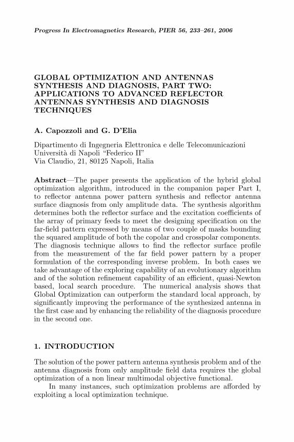
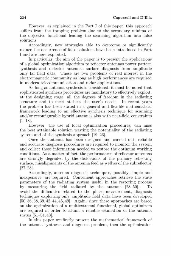
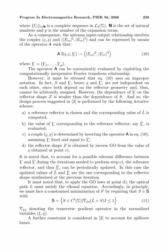
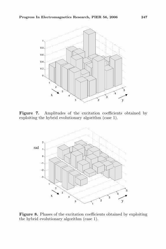
The amplitudes and the phases of the excitations coefficientssynthesized in case A1 are shown under Figs. 7 and 8, respectively,while the corresponding reflector shape is shown under Fig. 9.
As case A, case B involves a top flat beam within a toleranceequal to −0.5 and +0.5 dB, inside the regions of the (u, v) plane Ωi,and Ωe, respectively, shown in Fig. 10 and tailored to the Italianpeninsula, the Sicily and Sardinia islands, also reported in that figure.Again a maximum and a minimum level equal to −30 and −200 dBare prescribed outside Ωi and Ωe, respectively. Since the cross-polarcomponent should be as low as possible, only an upper bound equal to−70 dB is considered.
The synthesis has been performed with both the hybridevolutionary algorithm (case B1) and the quasi-Newton optimizer(BFGS) (case B2).
The co-polar amplitude synthesized in case B1 is shown underFig. 11 while the one synthesized in case B2 is presented inFig. 12. Again, the obtained results clearly show that the globaloptimizer outperforms the local one. In particular, the value of theobjective functional attained in case B1 is about 3 dB under the onecorresponding to case B2.
The cross-polar components obtained in case B1 and in case B2are depicted under Figs. 13 and 14, respectively. Again a worsening ofthe cross-polar level characterize the result obtained with the hybridapproach with respect to those corresponding to the local search.Anyway, as in case A, the result appears quite good, since the cross-polar remains under the −30 dB.
The amplitudes and the phases of the excitations coefficientssynthesized in case B1 are shown under Figs. 15 and 16, respectively,while the corresponding reflector shape is shown under Fig. 17.
3.2. Diagnosis of Reflector Antennas
The main results of an extensive numerical analysis involving thereflector diagnosis algorithm are now presented.
All the worked examples have involved a parabolic reflector (inits undistorted configuration) corresponding to a real antenna of theJPL/DSN, whose diameter and working frequency are equal to 34 mand about 12 GHz, respectively.
The antenna is fed at the focus by an elementary radiator withpure co-polar y-directed primary pattern of the type cosm(ϕ) withm = 9, providing a tapering of about 10 dB at the reflector edge. As

246 Capozzoli and D’Elia
v
u
Figure 5. Cross-polar synthesized by exploiting the hybridevolutionary algorithm (case 1).
v
u
Figure 6. Cross-polar synthesized by exploiting the local approach(case 1).
Progress In Electromagnetics Research, PIER 56, 2006 247
x y
5 4
3 2
Figure 7. Amplitudes of the excitation coefficients obtained byexploiting the hybrid evolutionary algorithm (case 1).
(case 1).
rad
x 4
y
5
3 2
1
Figure 8. Phases of the excitation coefficients obtained by exploitingthe hybrid evolutionary algorithm (case 1).

248 Capozzoli and D’Elia
Figure 9. Reflector shape synthesized by exploiting the hybridevolutionary algorithm (case 1).
i
e
u
v
Ω
Ω
Figure 10. Boundaries of the regions Ωj and Ωe defining the masksin the case B.

Progress In Electromagnetics Research, PIER 56, 2006 249
v
u
Figure 11. Co-polar synthesized by exploiting the hybrid evolutionaryalgorithm (case 2).
v
u
Figure 12. Co-polar synthesized by exploiting the local approach(case 2).

250 Capozzoli and D’Elia
v
u
Figure 13. Cross-polar synthesized by exploiting the hybridevolutionary algorithm (case 2).
u
Figure 14. Cross-polar synthesized by exploiting the local approach(case 2).

Progress In Electromagnetics Research, PIER 56, 2006 251
x y
5 4
3 2
1
Figure 15. Amplitudes of the excitation coefficients obtained byexploiting the hybrid evolutionary algorithm (case 2).
rad
x 4
y
5
3 2
1
Figure 16. Phases of the excitation coefficients obtained by exploitingthe hybrid evolutionary algorithm (case 2).

252 Capozzoli and D’Elia
Figure 17. Reflector shape synthesized by exploiting the hybridevolutionary algorithm (case 2).
a consequence, the x-component of Ea is zero, while the y-componentis proportional to cosm(θ)(1 + cos(θ)).
Concerning the basis function exploited in the expansion of theoptical path disturbance, we considered two different choices: theTchebytcheff and the Zernike polynomials [59]. Obviously, both arecomplete in the space of square integrable functions, although theZernike polynomials are orthogonal on the circle of unitary radius.A numerical analysis has been performed to chose the more convenientrepresentation.
In particular, the reflector deformations have been simulatedby representing the reflecting surface by means of Tchebytcheffpolynomials and by randomly and uniformly generating the expansioncoefficient (the simulated distortion has been suitably scaled to fix themaximum deformation).
Then, the far-field power pattern has been computed by using thecurrent method, that differs from the aperture approach exploited inthe retrieving process.
The retrieving step has been performed by using only the localalgorithm and the results obtained with both representations of theoptical path disturbance S have been compared. The numericalanalysis showed that Zernike polynomials are more convenient thanthe Tchebitchev ones, since, for a fixed degree of the reflector surface

Progress In Electromagnetics Research, PIER 56, 2006 253
distortion, they require a smaller number of iterations and a smallernumber of terms to get comparable reconstructing errors.
The second point to be faced concerns the efficient evaluationof the second term in the functional (15). This require an efficientevaluation of the derivatives of the expansion polynomials. This taskhas been easily accomplished by using the new recursive formulas forthe first order partial derivatives of the Zernike polynomials providedin [60].
However, it must be stressed that, as long as the degree of theexpansion coefficients of S is less then 9 and the range of variabilityof the expansion coefficient remains confined to the interval [−1, 1] theeikonal constraint has never been violated in our numerical analysis.
After this preliminary study, we started the analysis of theperformances of the Hybrid Algorithm.
As in the synthesis case, the most part of the numerical analysishas been devoted to enlighten those modules of the EvolutionaryAlgorithm that provide better performances and to set the searchingparameters.
Again, to make the performance of the Evolutionary Algorithmno worse than that of the local search, we inserted the individualcorresponding to the undistorted reflector in the initial population.
The performed numerical analysis involved several reflectordistortions with an optical path disturbance ranging from 3λ to4.5λ. The corresponding far-field power patterns have been simulatedby exploiting the current method and the effect of the noise andmeasurement errors have been taken into account by superimposingan additive random error, uniformly distributed with a maximumamplitude equal to −30 dB under the peak level of the simulated co-polar amplitude.
The far-field pattern corresponding to the undistorted reflector isshown in Fig. 18.
Later on, we explicitly present only one of the handled cases,corresponding to a maximum optical path disturbance on the reflectoraperture equal to 4.5λ, since the results involving the other cases arevery similar.
The optical path disturbance has been represented by means ofZernike polynomials up to the 7-th degree (36 expansion coefficients).
The simulated far-field patterns and the corresponding opticalpath distortions are shown in Figs. 19 and 20, respectively. Thedifferences between the simulated optical path and the one retrievedby applying the local search are displayed in Fig. 21.
Clearly, the local search was unable to retrieve the reflectordistortions.

254 Capozzoli and D’Elia
v
u
Figure 18. Squared amplitude of the copolar component radiated bythe undistorted reflector.
v
u
Figure 19. Squared amplitude of the copolar component radiated bythe distorted reflector.

Progress In Electromagnetics Research, PIER 56, 2006 255
s/ λ
Figure 20. Simulated optical path disturbance.
/λs∆
Figure 21. Difference between the simulated optical path disturbanceand the one retrieved by local search algorithm.
256 Capozzoli and D’Elia
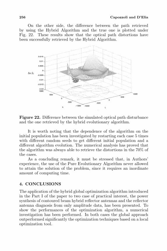
On the other side, the difference between the path retrievedby using the Hybrid Algorithm and the true one is plotted underFig. 22. These results show that the optical path distortions havebeen successfully retrieved by the Hybrid Algorithm.
/λs∆
Figure 22. Difference between the simulated optical path disturbanceand the one retrieved by the hybrid evolutionary algorithm.
It is worth noting that the dependence of the algorithm on theinitial population has been investigated by restarting each case 5 timeswith different random seeds to get different initial population and adifferent algorithm evolution. The numerical analysis has proved thatthe algorithm was always able to retrieve the distortions in the 70% ofthe cases.
As a concluding remark, it must be stressed that, in Authors’experience, the use of the Pure Evolutionary Algorithm never allowedto attain the solution of the problem, since it requires an inordinateamount of computing time.
4. CONCLUSIONS
The application of the hybrid global optimization algorithm introducedin the Part I of the paper to two case of practical interest, the powersynthesis of contoured beam hybrid reflector antennas and the reflectorantenna diagnosis from only amplitude data, has been presented. Toshow the performances of the optimization algorithm, a numericalinvestigation has been performed. In both cases the global approachoutperformed significantly the optimization techniques based on a localoptimization tool.

Progress In Electromagnetics Research, PIER 56, 2006 257
REFERENCES
1. Bucci, O. M., G. D’Elia, G. Mazzarella, and G. Panariello,“Antenna pattern synthesis: a new general approach,” Proc.IEEE, Vol. 82, No. 3, 358–371, 1994.
2. Bucci, O. M., G. D’Elia, and G. Romito, “Synthesis techniquefor scanning and/or reconfigurable beams reflector antennas withphase-only control,” IEE Proc. Microw. Antennas Propagat.,Vol. 143, 402–412, 1996.
3. Shen, B. and W. L. Stutzman, “Design of sperical trireflectorantennas with high aperture efficiency,” IEEE Trans. Antennasand Propagat., Vol. 41, No. 6, 778–786, 1993.
4. Searle, A. D. and B. S. Westcott, “Hybrid antenna synthesis forreconfigurable contoured beams,” IEE Proc. Pt. H., Vol. 140,No. 4, 263–268, 1993.
5. Botha, E. and D. A. McNamara, “Conformal array synthesisusing alternating projections with maximal likelihood estimationused in one of the projection operator,” Electronics Letters,Vol. 29, 1733–1734, 1993.
6. Clarricoats, P. J. B., A. D. Monk, and H. Zhou, “Array-fed reconfigurable reflectors for spacecraft systems,” ElectronicsLetters, Vol. 30, No. 8, 613–614, 1994.
7. Steiskal, H., “Synthesis of antenna patterns with imposed near-field nulls,” Electronics Letters, Vol. 30, No. 24, 2000–2001, 1994.
8. Duan, D. W. and Y. Rahmat-Samii, “A generalized diffractionsynthesis technique for high performance reflector antennas,”IEEE Trans. Antennas and Propagat., Vol. 43, No. 1, 27–40,1995.
9. Buckley, M. J., “Synthesis of shaped beams antenna patternsusing implicitly constrained current elements,” IEEE Trans.Antennas Propagat., Vol. 44, 192–197, 1996.
10. Vaskelainen, L. J., “Iterative least-squares synthesis methodsfor conformal array antennas with optimized polarization andfrequency properties,” IEEE Trans. Antennas Propagat., Vol. 45,No. 7, 1179–1185, 1997.
11. Landesa, L., F. Obelleiro, J. L. Rodriguez, and A. G. Pino,“Pattern synthesis of array antennas in presence of conductingbodies of arbitrary shape,” Electronics. Letters, Vol. 33, No. 18,1512–1513, 1997.
12. Obelleiro, F., L. Landesa, J. L. Rodriguez, A. G. Pino, andM. R. Pino, “Directivity optimisation of an array antennawith obstacles within the near-field region,” Electronics Letters,

258 Capozzoli and D’Elia
Vol. 33, No. 25, 2087–2088, 1997.13. Landesa, L., F. Obelleiro, J. L. Rodriguez, J. A. Rodriguez,
F. Ares, and A. G. Pino, “Pattern synthesis of array antennaswith additional isolation of near-field arbitrary objects,”Electronics Letters, Vol. 34, No. 16, 1540–1541, 1998.
14. Hay, S. G., “Dual-shaped-reflector directivity pattern synthesisusing the successive projections method,” IEE Proc. Microw.Antennas Propagat., Vol. 146, No. 2, 119–124, 1999.
15. Hoferer, R. A. and Y. Rahmat-Samii, “A GO-subreflectorimplementation methodology using a Fourier-Jacobi surfaceexpansion,” Proc. of the IEEE Antennas and PropagationSociety, Vol. 4, 2328–2331, 1999.
16. Bucci, O. M., A. Capozzoli, and G. D’Elia, “An effectivepower synthesis technique for shaped, double-reflector multifeedantennas,” Journal of Electromagnetic Waves and ApplicationsVol. 17, No. 5, 743–754, 2003.
17. Bucci, O. M., A. Capozzoli, and G. D’Elia, “Reconfigurableconformal array synthesis with near field constraints,” PIERS2000, Cambridge, Massachusetts, USA, July 5–14, 2000.
18. Bucci, O. M., A. Capozzoli, and G. D’Elia, “Synthesis of reflectorantennas with near-field constraints,” Proceedings of the IEEETransactions on Antennas and Propagation Society, Vol. 1, 562–565, 2001.
19. Bucci, O. M., A. Capozzoli, and G. D’Elia, “A globaloptimization technique in the synthesis of reflector antennas,”17th Annual Review of Progress in Applied ComputationalElectromagnetics, March 19–23, 2001.
20. Haupt, R. L., “Thinned arrays using genetic algorithms,” IEEETrans. Antennas and Propagat., Vol. 42, No. 7, 993–999, 1994.
21. Mitchell, R. J., B. Chambers, and A. P. Anderson, “Arraypattern synthesis in the complex plane optimised by a geneticalgorithm,” Electronics Letters, Vol. 32, No. 20, 1843–1845, 1996.
22. Johnson, J. M. and Y. Rahmat Samii, “Genetic algorithms inengineering electromagnetics,” IEEE Antennas Propagat. Mag.,Vol. 39, No. 4, 7–25, 1997.
23. Ferreira, J. A. and F. Ares, “Pattern synthesis of conformalarrays by the simulated annealing technique,” ElectronicsLetters, Vol. 33, No. 14, 1187–1189, 1997.
24. Yan, K.-K. and Y. Lu, “Side lobe reduction in array-patternsynthesis using genetic algorithm,” IEEE Trans. Antennas andPropagat., Vol. 45, No. 7, 1117–1122, 1997.

Progress In Electromagnetics Research, PIER 56, 2006 259
25. Markus, K. and L. Vaskelainen, “Optimisation of synthesisedarray excitations using array polynome complex root swappingand genetic algorithms,” IEE Proc. Microw. Antennas Propagat.,Vol. 145, No. 6, 460–464, 1998.
26. Marcano, D. and F. Duran, “Synthesis of antenna arrays usinggenetic algorithms,” IEEE Antennas and Propagation Magazine,Vol. 42, No. 3, 12–20, 2000.
27. Safak, M., “Limitation on reflector antenna gain by randomsurface errors, pointing errors, and the angle-of arrival jitter,”IEEE Trans. Antennas and Propagat., Vol. 38, No. 1, 117–121,1990.
28. Rochblatt, D. J. and Y. Rahamat-Samii, “Effects of measurementErrors on microwave antenna holography,” IEEE Trans.Antennas and Propagat., Vol. 39, No. 7, 933–942, 1991.
29. Ramson, P. L. and R. Mittra, “A method for locating defectiveelements in large phased array,” Phased Arrays, A. A. Oliner andG. H. Knitt (Eds.), 351–356, 1972.
30. Bennet, J. C, A. P. Anderson, P. A. McInnes, andA. J. T. Whitaker, “Microwave holographic metrology of large re-flector antennas,” IEEE Trans. Antennas and Propagat., Vol. 24,No. 5, 293–303, 1976.
31. Rahamat-Samii, Y., “Surface diagnosis of large reflector antennasusing microwave holographic metrology: an iterative approach,”Radio Science, Vol. 19, No. 5, 1205–1217, 1984.
32. Rahamat-Samii, Y., “Microwave holography of large reflectorantennas-simulation algorithms,” IEEE Trans. Antennas andPropagat., Vol. 33, No. 11, 1194–1203, 1985.
33. Morris, D., “Phase retrieval in the radio holography of reflectorantennas and radio telescopes,” IEEE Trans. Antennas andPropagat., Vol. 33, No. 7, 749–755, 1985.
34. Morris, D., “Correction to: phase retrieval in the radioholography of reflector antennas and radio telescopes,” IEEETrans. Antennas and Propagat., Vol. 33, No. 12, 1419, 1985.
35. Anderson, A. P. and S. Sali, “New possibilities for phaselessmicrowave diagnostics. Part 1: Error reduction techniques,” IEEProceedings Pt. H, Vol. 132, No. 5, 291–298, 1985.
36. Gardenier, P. H., C. A. Lim, D. G. H. Tan, and R. H. T. Bates,“Aperture distribution phase from single radiation patternmeasurement via Gerchberg-Saxton algorithm,” ElectronicLetters, Vol. 22, No. 2, 113–115, 1986.
37. Rahamat-Sarnii, Y., “Correction to: microwave holography of
260 Capozzoli and D’Elia
large reflector antennas-simulation algorithms,” IEEE Trans.Antennas and Propagat., Vol. 34, No. 6, 853, 1986.
38. Morris, D., H. Hein, H. Steppe, and J. W. M. Baars, “Phaseretrieval radio holography in the Fresnel region: tests on the 30 mtelescope at 86 GHz,” IEE Proceedings Pt. H, Vol. 135, No. 1, 61–64, 1988.
39. Anderson, A. P. and J. E. M. McCorrnack, “Phase retrievalenhancement of antenna metrology data,” Electronic Letters,Vol. 24, No. 19, 1243–1244, 1988.
40. Rochblatt, D. J. and Y. Rahamat-Samii, “Effects of measurementerrors on microwave antenna holography,” IEEE Trans. Anten-nas and Propagat., Vol. 39, No. 7, 933–942, 1991.
41. Wood, P. J., “A new methodology for reconstructing aperturefield from spherical surface data, with application to the arraydiagnostic,” IEEE Trans. Antennas and Propagat., Vol. 39, 1436–1441, 1991.
42. Morris, D., J. H. Davis, and C. E. Mayer, “Experimentalassessment of phase retrieval holography of radiotelescope,” IEEProceedings Pt. H, Vol. 138, No. 3, 243–247, 1991.
43. Morris, D., “Simulated annealing applied to the Misell algorithmfor phase retrieval,” IEE Proceedings Pt. H, Vol. 143, No. 4, 298–303, 1991.
44. Anderson, A. P., Y. D. Cheung, and J. Junkin, “Phase retrievalnear-field metrology of unknown aperture,” Electronic Letters,Vol. 28, No. 5, 454–455, 1992.
45. Lord, J. A., G. G. Cook, and A. P. Anderson, “Reconstructionof the excitation of an array antenna from measured near-fieldintensity using phase retrieval,” IEE Proceedings-Pt. H, Vol. 139,No. 4, 392–396, 1992.
46. Rochblatt, D. J., P. M. Withington, and H. J. Jackson, “DSS-24 microwave holography measurement,” NASA/JPL TDAProgress Report, 1995.
47. Richter, P. H. and D. J. Rochblatt, “A microwave performancecalibration system for NASA’s deep space network antennas,Part 1: Assessment of antenna gain and pointing, and calibrationof radio sources,” 10th International Conference on Antennasand Propagation, Edinburgh, April 1997.
48. Rochblatt, D. J., P. H. Richter, and T. Y. Otoshi, “Amicrowave performance calibration system for NASA’s deepspace network antennas, Part 2: Holography, alignment, andfrequency stability,” 10th International Conference on Antennas

Progress In Electromagnetics Research, PIER 56, 2006 261
and Propagation, Edinburgh, April 1997.49. Leone, G. and R. Pierri, “Reflector antenna diagnosis from
phaseless data,” IEEE Trans. Antennas and Propagat., Vol. 45,No. 8, 1236–1244, 1997.
50. Bucci, O. M., G. D’Elia, and G. Romito, “Reflector distortionsdiagnosis from far-field amplitude pattern,” IEEE Trans.Antennas and Propagat., Vol. 43, No. 11, 1217–1225, 1995.
51. Bucci, O. M., A. Capozzoli, and G. D’Elia, “A hybridevolutionary algorithm in the diagnosis of reflector distortions,”JINA 98, International Symposium on Antennas, Nizza, Francia,November 17–19, 1998.
52. Bucci, O. M., A. Capozzoli, and G. D’Elia, “A hybridevolutionary algorithm in the diagnosis of reflector distortionsfrom far-field amplitude pattern,” Atti della Fondazione Ronchi,Vol. 54, No. 3, 503–519, 1999.
53. Bucci, O. M., A. Capozzoli, and G. D’Elia, “A Lamarckian —type evolutionary algorithm for large reflector diagnosis,” XXVIGeneral Assembly of the International Union of Radio Science,Toronto, Canada, August 13–21, 1999.
54. Bucci, O. M., A. Capozzoli, and G. D’Elia, “Diagnosis ofarray faults from far-field amplitude-only data,” IEEE Trans.Antennas and Propagat., Vol. 48, 5, 647–652, 2000.
55. Tikhonov, A. and V. Arsenine, Methodes de Resolution deProblemes Mal Poses, MIR, 1976.
56. Lamb, J. W. and A. D. Olver, “Blockage due to subreflectorsupports in large radiotelescopes antennas,” IEE Proceedings,133, Pt. H, 1, 43–49, 1986.
57. Moldsvor, A. and P. Kildal, “Analysis of aperture blockage inreflector antennas by using obstacle-located blockage currents,”IEEE Transactions on Antennas and Propagation, Vol. 40, 1,1992.
58. Luenberger, D. G., Linear and Nonlinear Programming, Addison-Wesley, 1984.
59. Born, M. and M. Wolf, Principles of Optics, Pergamon Press,1970.
60. Capozzoli, A., “On a new recursive formula for zernikepolynomials first order derivatives,” Atti della Fondazione G.Ronchi, Anno LIV, No. 6, Novembre–Dicembre 1999.