global positioning in harsh environments237461/fulltext01.pdf · technical report, ide0504, january...
TRANSCRIPT

Technical Report, IDE0504, January 2005
Global Positioning
in Harsh Environments
Master’s Thesis in Computer Systems Engineering
Bernd Resch, Peter Romirer-Maierhofer
School of Information Science, Computer and Electrical Engineering Halmstad University

Global Positioning in Harsh Environments
Master’s Thesis in Computer Systems Engineering
School of Information Science, Computer and Electrical Engineering Halmstad University
Box 823, S-301 18 Halmstad, Sweden
January 2005

Acknowledgements
We would like to thank Urban Bilstrup from Halmstad University as well as Mikael Taveniku
and Christian Wigren from XCube Communications Inc. for supervising our project.
Furthermore, we want to express our thanks to Latef Berzenji for proofreading our thesis.
Finally, we would like to commonly thank everybody who contributed in his or her way to the
accruement of this thesis.
Bernd
I want to show gratitude to my family for perfectly supporting me during my whole life in all
my decisions and ways. Moreover, I want to thank my life companion Katrin for being patient
with me in stressful times and for offering me her warm devotion and magnanimous
understandings during the creation of this thesis.
Peter
I would like to thank my family for giving me their support during my study, specially my
father for his indefatigable financial support. Moreover, I would like to express my gratitude
to all those who made my study in Sweden possible. I extend my sincere appreciation to all
my friends for giving me lots of relaxing and exhilarating moments in demanding times.

Description of cover page picture: Technical structure of the innovative approach for
measuring GSM cell fingerprints developed within this
thesis.

i
Preface
Team Members: Bernd Resch
Peter Romirer-Maierhofer
Institution: Halmstad University, January 2005
Programme of Study: Master’s programme for computer systems engineering or electrical
engineering
Title of the Thesis: Global Positioning in Harsh Environments
Supervisors: Urban Bilstrup, Halmstad University
Mikael Taveniku, XCube Communications Inc.
Christian Wigren, XCube Communications Inc.
Keywords
1. Keyword: GPS positioning problems
2. Keyword: GSM positioning
3. Keyword: Evaluation of location estimation methods
4. Keyword: Database comparison
5. Keyword: Database correlation

ii

iii
Abstract
As global location systems offer only restricted availability, they are not suitable for a world-
wide tracking application without extensions. This thesis contains a goods-tracking solution,
which can be considered globally working in contrast to formerly developed technologies. For
the creation of an innovative approach, an evaluation of the previous efforts has to be made.
As a result of this assessment, a newly developed solution is presented in this thesis that uses
the Global Positioning System (GPS) in connection with the database correlation method
involving Global System for Mobile Communications (GSM) fingerprints. The database
entries are generated automatically by measuring numerous GSM parameters such as Cell
Identity and signal strength involving handsets of several different providers and the real
reference position obtained via a high sensitivity GPS receiver.

iv

v
List of Figures
Figure 1: GPS Satellite Constellation, [GARM05] © Garmin Corp. 2005................................ 2
Figure 2: Galileo System Architecture, with permission of Javier Benedicto, [BENE04], ©
ESA Navigation Department..................................................................................... 10
Figure 3: Loran-C Pulse Sequence, with permission of Tron-Erik Tomtum, Northwest
European Loran-C System, Coordinating Agency Office, [PROC01]. .................... 12
Figure 4: Time Difference Measurement, with permission of Tron-Erik Tomtum, Northwest
European Loran-C System, Coordinating Agency Office, [KVAE04]..................... 13
Figure 5: Eurofix System Setup. .............................................................................................. 14
Figure 6: A-GPS System Structure. ......................................................................................... 18
Figure 7: Reduction of Searched Frequency Bins by Parallel Correlation, with permission of
Frank van Diggelen, Global Locate Inc., [DIGG01]................................................. 21
Figure 8: Localisation Using Cell Identity. .............................................................................. 23
Figure 9: Positioning Based on Cell Identity and Timing Advance......................................... 25
Figure 10: Principle of Forced Handover................................................................................. 26
Figure 11: Localisation by referring to Cell Identity, Timing Advance and Signal Strength. . 27
Figure 12: Principle of Positioning Based on Angle of Arrival. .............................................. 30
Figure 13: Positioning Principle of TOA. ................................................................................ 32
Figure 14: Principle of Uplink Time Difference of Arrival. .................................................... 33
Figure 15: Intersection of Hyperbolae within E-OTD. ............................................................ 36
Figure 16: Dual Channel Route Estimation without Averaging, [KAN03] © 2003 IEEE. ..... 41
Figure 17: Dual Channel Route Estimation with Averaging, [KAN03] © 2003 IEEE. .......... 42
Figure 18: Main Architecture of the Database Comparison System Applied on a GSM
Network. ................................................................................................................. 43
Figure 19: System Structure of the Innovative Approach........................................................ 53
Figure 20: AT Command Syntax. ............................................................................................ 54
Figure 21: Element Structure of the XML Configuration File................................................. 56
Figure 22: Screenshot About Output of GPS 12 Receiver....................................................... 67
Figure 23: Measurement Route on the Campus of Halmstad University, [HOEG05] modified
and reprinted with permission of Hans Halling...................................................... 70
Figure 24: Fingerprint Parameters Saved in a Text File. ......................................................... 70
Figure 25: Practical Application Scenario of MPP and MLP. ................................................. 87
Figure 26: MLP Protocol Stack................................................................................................ 88

vi

vii
List of Tables
Table 1: Different Categories of Dilution of Precision. ............................................................. 6
Table 2: Loran-C Phase Coding. .............................................................................................. 12
Table 3: Evaluation Summary of A-GPS. ................................................................................ 20
Table 4: Comparison Global Locate Inc. with SiRF Technology Inc...................................... 21
Table 5: Evaluation Summary of Indoor GPS.......................................................................... 22
Table 6: Evaluation Summary of Cell-ID. ............................................................................... 24
Table 7: Evaluation Summary of Cell-ID and Timing Advance.............................................. 26
Table 8: Evaluation Summary of Cell-ID combined with TA and RXLEV. ........................... 28
Table 9: Evaluation Summary of Cell-ID combined with TA and RXLEV. ........................... 29
Table 10: Results of Real World Experiment Carried Out by Radiolinja and Nokia. ............. 30
Table 11: Evaluation Summary of AOA.................................................................................. 31
Table 12: Evaluation Summary of Uplink TDOA. .................................................................. 34
Table 13: Evaluation Summary of E-OTD............................................................................... 38
Table 14: Evaluation Summary of OTDOA............................................................................. 40
Table 15: Evaluation Summary of the Database Correlation Method. .................................... 44
Table 16: Evaluation Summary of Statistical Modelling. ........................................................ 47
Table 17: Summary of Evaluation Results............................................................................... 48
Table 18: Employed AT Commands........................................................................................ 55
Table 19: Structure of Proactive SIM Command..................................................................... 60
Table 20: Sample AT Command Sequence for Interfacing SIM AT....................................... 61
Table 21: Sample Response to Location Information Request. ............................................... 62
Table 22: Sample Network Measurement Result..................................................................... 64
Table 23: Converting of Parameter RXLEV............................................................................ 65
Table 24: Format of BSIC. ....................................................................................................... 66
Table 25: Structure of $GPGGA Sentence............................................................................... 68
Table 26: Hardware Used for Testing. ..................................................................................... 69
Table 27: Sample Database Entry. ........................................................................................... 71

viii

ix
Abbreviations
3G … Third Generation 3GPP … Third Generation Partnership Project 4G … Fourth Generation A-GPS … Assisted GPS AOA … Angle of Arrival BCC … Base Station Colour Code BCCH … Broadcast Control Channel BS … Base Station BSC … Base Station Controller BTS … Base Transceiver Station, GSM equivalent to BS C/A … Coarse Acquisition CDMA … Code Division Multiple Access CI … Cell Identity CI+TA … Positioning Method Based on CI and TA CI+TA+RXLEV … Positioning Method Based on CI, TA and RXLEV CR … Carriage Return CRC … Cyclic Redundancy Check DGNSS … Differential GNSS DoD … Department of Defense DOP … Dilution of Precision DS-CDMA … Direct Sequence - CDMA DTD … Document Type Definition E-OTD … Enhanced Observed Time Difference EF … Elementary File EGNOS … European Geostationary Navigation Overlay Service ELIS … Emergency Location Immediate Service ELRS … Emergency Location Reporting Service ESA … European Space Agency ETSI … European Telecommunications Standards Institute FCC … Federal Communications Commission FEC … Forward Error Correction GCC … Galileo Control Centre GDOP … Geometric DOP GMPC … Gateway Mobile Positioning Centre GNSS … Global Navigation Satellite System GPRS … General Packet Radio System GPS … Global Positioning System GRI … Group Repetition Interval GSM … Global System for Mobile Communications GTD … Geometric Time Difference GTS … GSM Technical Specification HDOP … Horizontal DOP HP … High Precision IP … Internet Protocol IPDL … Idle Period on the Downlink ITS … Intelligent Transportation System LCS … Location Service LMU … Location Measurement Unit

x
LOP … Line of Position LOS … Line of Sight LS … Location Server MCS … Master Control Station MEO … Medium Earth Orbit MLC … Mobile Location Centre MLP … Mobile Location Protocol MPP … Mobile Positioning Protocol MPS … Mobile Positioning System MS … Mobile Station MSC … Mobile Switching Centre NCC … Network Colour Code NMEA … National Marine Electronics Association NMR … Network Measurement Result OTD … Observed Time Difference OTDOA … Observed Time Difference of Arrival PDOP … Positional DOP PDU … Protocol Data Unit PSK … Phase Shift Keying PRN … Pseudorandom Noise RNC … Radio Network Controller RSCP … Received Signal Code Power RTCM … Radio Technical Commission for Marine Services RTD … Real Time Difference RTT … Round Trip Time RXLEV … Received Signal Strength SA … Selective Availability SGSN … Serving GPRS Support Node SIM … Subscriber Identity Module SIM AT … SIM Application Toolkit SLIS … Standard Location Immediate Service SLRS … Standard Location Reporting Service SMG … Special Mobile Group SMS … Short Message Service SP … Standard Precision SS … Supplementary Service SSL … Secure Socket Layer TA … Timing Advance TDOA … Time Difference of Arrival TDOP … Time DOP TOA … Time of Arrival TLRS … Triggered Location Report Service TTTF … Time-to-first-fix UMTS … Universal Mobile Telecommunications System USSD … Unstructured Supplementary Service Data UTC … Coordinated Universal Time UTSFM … Urban Three-state Fade Model VDOP … Vertical DOP WGS … World Geodetic System

xi
Contents
1 INTRODUCTION............................................................................................................................... 1 1.1 GLOBAL POSITIONING SYSTEM.................................................................................................... 2 1.1.1 THE SYSTEM ARCHITECTURE ....................................................................................................... 2 1.1.2 THE SIGNAL STRUCTURE ............................................................................................................... 3 1.1.3 THE POSITIONING TECHNIQUE ..................................................................................................... 4 1.1.4 ERRORS AFFECTING THE ACCURACY......................................................................................... 5 1.2 SIGNIFICANCE OF GPS RECEIVERS .............................................................................................. 6 1.3 GPS SIGNAL FADING IN URBAN ENVIRONMENTS ................................................................... 7
2 TECHNOLOGICAL ALTERNATIVES TO GPS........................................................................... 9 2.1 GALILEO ............................................................................................................................................. 9 2.2 GLONASS .......................................................................................................................................... 10 2.3 LORAN-C........................................................................................................................................... 11 2.4 EUROFIX ........................................................................................................................................... 13
3 EVALUATION OF FORMER APPROACHES ............................................................................ 17 3.1 ASSISTED GPS.................................................................................................................................. 17 3.2 INDOOR GPS..................................................................................................................................... 20 3.3 GSM LOCALISATION...................................................................................................................... 22 3.3.1 CELL-INFORMATION BASED POSITIONING ............................................................................. 23 3.3.2 AOA .................................................................................................................................................... 30 3.3.3 TIME OF ARRIVAL .......................................................................................................................... 31 3.3.4 UPLINK TIME DIFFERENCE OF ARRIVAL.................................................................................. 32 3.3.5 DOWNLINK TIME DIFFERENCE OF ARRIVAL .......................................................................... 34 3.4 COMBINING GSM AND GPS .......................................................................................................... 41 3.5 UMTS LOCALISATION.................................................................................................................... 42 3.6 DATABASE COMPARISON ............................................................................................................ 43 3.7 KYTOONS.......................................................................................................................................... 44 3.8 HYBRID APPROACHES................................................................................................................... 45 3.9 STATISTICAL MODELING ............................................................................................................. 46 3.10 SUMMARY ........................................................................................................................................ 47
4 INNOVATIVE APPROACH ........................................................................................................... 51 4.1 MOTIVATION ................................................................................................................................... 51 4.2 TECHNICAL DESCRIPTION ........................................................................................................... 52 4.2.1 ATTENTION COMMANDS.............................................................................................................. 54 4.2.2 SUBSCRIBER IDENTITY MODULE APPLICATION TOOLKIT.................................................. 55 4.3 PRACTICAL IMPLEMENTATION .................................................................................................. 56 4.3.1 MAIN PROGRAMME ....................................................................................................................... 56 4.3.2 SUBSCRIBER IDENTITY MODULE APPLICATION TOOLKIT INTERPRETER ...................... 60 4.3.3 MEASUREMENT OF REFERENCE POSITION.............................................................................. 66 4.4 TESTING RESULTS.......................................................................................................................... 69

xii
5 FUTURE WORK .............................................................................................................................. 73 6 CONCLUSION.................................................................................................................................. 75 REFERENCES.................................................................................................................................................... 77 APPENDIX A: MOBILE PROTOCOLS.......................................................................................................... 87
MOBILE POSITIONING PROTOCOL............................................................................................................ 87 MOBILE LOCATION PROTOCOL ................................................................................................................ 88

Introduction
1
1 Introduction
Currently, Global Positioning System (GPS) signals are not accessible in certain environments
like urban regions or indoors, which raises two unresolved questions considering a world-
wide goods tracking solution.
The first challenge is to make GPS usable in urban canyons between skyscrapers, where GPS
signals are negatively influenced by multipath effects and the shading caused by high
buildings. Secondly, the comparably weak GPS signal is attenuated by walls so that the
system is not usable indoors. Hence, either the signal must be brought into the building or
GPS is to be combined with a local positioning method using stronger signals that can
penetrate the walls.
In order to be able to formulate concepts and possible applications to overcome the problems
mentioned above, the commonly used technology of GPS has to be investigated first. After
that, the benefits and disadvantages of existing positioning systems versus GPS must be
examined and critically viewed. Then, several existing solutions for the stated positioning
problem should be elucidated and evaluated based on several criteria such as accuracy, world-
wide availability and requirements necessitated due to a possible application scenario. In fact,
this consistent evaluation is the primary goal of the project in question. Finally, an innovative
approach, which has to be verified by a meaningful demonstration, can be derived from the
results of the performed evaluation.
Technical facts of the Global Positioning System (GPS), which is currently the most
important positioning technology, are presented in the first chapter and a brief illustration of
several technological alternatives to GPS is given in section two. Thereafter, a description and
a profound evaluation of former approaches to overcome the aforesaid positioning problems
are examined in the next part of the thesis. Chapter four contains the technical description and
the motivation for the conception of the innovative method created within this project.
Finally, the conclusion provides a summary of the practical implementation of the new
approach as well as a future outlook elucidating possible further developments of the project
outcomes.

Global Positioning in Harsh Environments
2
1.1 Global Positioning System Developed for military use by the United States Department of Defense (DoD), the Global
Positioning System (GPS) has achieved great importance also in the field of civil application.
Examples in this context are intelligent traffic management and navigation services, tracing of
goods, localisation of mobile phones in case of emergency calls and so on. Another important,
but often less noticed application is time synchronisation via time signals broadcasted by
satellites.
1.1.1 The System Architecture
The architecture of GPS is divided into three different sections. The first one is made up by
the navigation satellites. GPS involves a constellation of 24 satellites, which are at semi
synchronous altitude of about 11.000 nautical miles or about 20.000 km, respectively. These
satellites are moving on six different orbital planes, each including four satellites. The
corresponding orbital period is twelve hours. In relation to the equator, these planes are
inclined at 55°. Figure 1, taken from [GARM05] roughly illustrates the disposition of the GPS
satellites.
Figure 1: GPS Satellite Constellation, [GARM05] © Garmin Corp. 2005.
The constellation shown above assures that at least four satellites are visible 24 hours a day all
over the world. This is important since GPS requires a minimum of four satellites for accurate
three-dimensional positioning. In fact, the number of visible satellites is often higher and can
reach an amount of up to ten. An important fact to mention is that positioning requires very
exact timing accuracy. This is why all early GPS satellites were equipped with Cesium and
Rubidium atomic clocks. Newer generations of GPS satellites rely on the Rubidium standard.

Introduction
3
The accuracy of these clocks is within a few nanoseconds of global coordinated world time
(UTC).
The second section of GPS, which is situated on earth, is used for the control of the satellites.
Within in this section of GPS, one can find a master control station (MCS) located at
Schriever Air Force Base, Colorado Springs, CO, USA and five monitor stations distributed
over the world. Data recorded by the monitor stations are processed at the master control
station. After doing the corresponding calculations, correction messages are sent to the
satellites. The purpose of these corrections is to maintain perfect accuracy as far as orbital
location and the system-time of the satellites are concerned.
The third and last section of GPS simply refers to the big field of GPS users. Within this
section, the communication is only one-directional from the satellites to the GPS receivers.
Possible errors have to be corrected by the GPS end-devices or via Differential GPS (DGPS),
which is explained in subsection 1.1.4.
1.1.2 The Signal Structure
A GPS receiver is able to calculate its position upon receiving navigation messages, which are
packed into two pseudorandom noise (PRN) code sequences. The Coarse Acquisition (C/A)
code is a 1023 bits long sequence being repeated every millisecond. Furthermore, this code is
clocked with 1.023 MHz. The second code sequence (Y-code), which is repeated every week,
is encrypted and 6 trillion bits long. Its clock rate is 10.23 MHz. By processing navigation
messages, receivers obtain information about the position of the individual satellites and the
system time. The C/A-code has great importance for civil use since it is unencrypted and thus
available to all GPS receivers. Moreover, a high repetition rate guarantees a short
reacquisition time. Each satellite is sending its messages via two different frequencies, which
are called L-band frequencies. L1 can be found at 1.575,42 MHz and L2 is placed at 1.227,60
MHz. These frequencies were chosen in order to be able to compensate for atmospheric
phenomena. For example, the two different frequencies can be utilised to determine and
cancel out ionospheric effects. The fact that all satellites are sending at the same frequencies
requires a Code Division Multiple Access (CDMA) interface. This is done by a set of Gold
codes, which means that each satellite transmits a unique code that is not interfering with the
codes of other satellites. The carriers are phase shift key (PSK) modulated by the use of the
C/A and the Y-code, which results in two spread-spectrum signals having a bandwidth of
2.046 MHz and 20,46 MHz. One important aspect in this concern is the fact that spread-

Global Positioning in Harsh Environments
4
spectrum techniques allow GPS to work at very low signal strengths, which means that GPS
signals are received at a range between -160 and -166 dBW.
In the current implementation, only the L1 band contains both, the Y-code and the civil C/A-
code. Within modernisation initiatives, a new, more robust civil signal will be added to the L2
band. In addition, a third frequency band operating at 1.176,45 MHz is planned to be
introduced by the end of 2005.
1.1.3 The Positioning Technique
GPS utilises the principle of time difference of arrival (TDOA), which indicates that a 3D-
position can be calculated by knowing the distances to any three points in space. The
distances are quantified by measuring the propagation time of the GPS signal received from
several satellites. In other words, by looking at the C/A code, a receiver knows when the
signal was sent and then it has to compare that time with the receiver internal clock. By
multiplying the resulting time interval with the speed of light, the distance to the satellite can
be calculated. The obtained distance is called pseudorange because of the fact that there is
always a small timing offset between the satellite clock and the receiver clock. This timing
offset can be determined by involving a fourth satellite. Thus, an accurate three-dimensional
positioning requires the signal availability from four different satellites. It has to be mentioned
that even very small timing offsets can cause large positioning errors due to the fact that the
high value of speed of light is involved in the calculations. As stated in [COOP94], the
equation of the noiseless pseudorange to a single satellite is
2 2 2( ) ( ) ( )S R S R S RX X Y Y Z Z c tψ δ= − + − + − + ⋅
where index S depicts the satellite coordinates and R represents the coordinates of the GPS
receiver. As mentioned above, c stands for the speed of light and δt symbolises the clock
offset at the receiver. Looking at the above formula, it is obvious that involving four GPS
satellites is necessary for accurate positioning since the equation contains four unknown
values. To sum up, one can state that these four unknown values are the coordinates of the
GPS receiver and the timing offset between the involved satellites and the GPS receiver. Due
to the fact that all satellites are synchronised to each other, this timing offset is constant for
every satellite.
GPS is based on the World Geodetic System (WGS-84), which is an earth-centered earth-
fixed format founded by a geocentric equipotential ellipsoid. As stated in [HOFM97; p. 31],
the WGS-84 ellipsoid is defined by the parameters semimajor axis of the ellipsoid, zonal
coefficient of second degree, angular velocity of the earth and the earth’s gravitational

Introduction
5
constant. A detailed explanation of the coordinate systems usable for all Global Navigation
Satellite Systems (GNSSs) can be found in [HOFM97, pp. 29-36].
Kalman filtering is used in order to process the obtained pseudoranges at the receiver. Further
details about this rather sophisticated method can be found in [COOP94].
1.1.4 Errors Affecting the Accuracy
Some error sources of GPS have to be taken into consideration. First of all, there are
ephemeris errors, which means that satellite signals transmitted from an altitude of about
20.000 km are often affected by forces like solar winds and earth gravitational pull
[COOP94]. Normally, the inaccuracy caused by ephemeris errors is between 15 and 20
meters.
Propagation errors are provoked by the fact that a GPS signal has to propagate through
different layers of the earth’s atmosphere. For instance, the ionosphere adds an inaccuracy of
about 20 meters to the pseudoranges. Furthermore, there is an additional error caused by the
GPS signal propagating through the troposphere. Different weather conditions make it
impossible to predict this error, which is between three and four meters.
Another important error source was the Selective Availability (SA). This error was introduced
by the DoD in order to make the GPS positioning inaccurate for civil use while preserving the
best positioning performance only for military use. However, SA was deactivated on 1st May
2000. A method originally introduced to overcome the inaccuracy caused by SA is
Differential GPS (DGPS), which involves stationary GPS receivers situated at known
positions. The fact that the positions of such stationary receivers are known reduces the
number of unknown variables within the GPS calculation. The additional knowledge can be
utilised to get important information about the current GPS timing error. Transmitting the
resulting correction data to moving GPS receivers via radio waves is an efficient way to
improve the positioning accuracy of these GPS receivers.
A further important aspect influencing the precision of the obtained GPS position is the
geometry of the satellites involved in the pseudorange measurements. A parameter to quantify
the quality of this geometry is the Dilution of Precision (DOP) factor. It should be mentioned
that this geometry changes as the satellites are moving along their orbital planes, which means
that the DOP values vary over time. No measurement values are necessary for the calculation
of DOP values, which can be performed by the use of knowledge about the satellite
constellation. Low values of DOP indicate high positioning accuracy. A commonly used
threshold value in this context is five, which denotes that positions calculated under a DOP

Global Positioning in Harsh Environments
6
less or equal five are considered to be accurate. Different categories of DOP are generally
defined as follows.
PDOP Positional DOP Accuracy referring to position
TDOP Time DOP Accuracy referring to time
GDOP Geometric DOP Accuracy referring to position and time
HDOP Horizontal DOP Accuracy referring to two-dimensional positioning
VDOP Vertical DOP Accuracy referring to height
Table 1: Different Categories of Dilution of Precision.
Further details about DOP and its determinism can be found in [HOFM97; pp. 273-277].
1.2 Significance of GPS Receivers When considering GPS signal availability in harsh environments like urban areas, the
performance of the GPS receiver itself also has to be properly investigated. In an early
research presented by Melgard et al. [MELG94], different GPS receivers were evaluated in
residential and downtown areas of Calgary. Melgard et al. showed that a GPS receiver
equipped with a narrow correlator provides best results. The narrow correlator, introduced in
1991, can be seen as the first method to compensate for multipath effects at the GPS receivers,
which is also called multipath mitigating. Another important performance characteristic of a
GPS receiver is a low signal reacquisition delay. Consequently, the receiver should be able to
recalculate its current position as fast as possible after periods of blocked GPS signals, which
can occur due to obstacles like high buildings in an urban canyon. The fact that the signal
availability between different types of GPS receivers can vary by an amount of up to 60%
indicates the importance of a GPS receiver performance analysis when using it in a critical
surrounding.
More recent research works carried out in [MACG02] also pointed out the importance of
choosing a well-performing GPS receiver in harsh environments. MacGougan et al. described
the performance of a twelve-channel L1 receiver produced by SiRF Technology Inc. This
high sensitivity receiver was specially designed to work in demanding environments like
urban canyons and indoors.
An important ability of GPS receivers is multipath mitigating, as already mentioned above.
By diffraction and reflection, the GPS signal is prone to multipath effects in urban
environments. Several algorithms of multipath mitigating are presented and evaluated by
Mike Braasch in [BRAA01a]. Multipath effects add a considerable inaccuracy to the
pseudorange measurements, which can be expressed by a multipath error envelope. As shown

Introduction
7
in [BRAA01a], there is a direct relationship between this error envelope and the discriminator
function used at the receiver. That is why a first concept to overcome multipath effects is to
shape the discriminator function, which is often done by a narrow correlator or by a
combination of two discriminators, which are obtained employing two different narrow
correlators. Such a combination is called strobe correlator. The second concept is to shape the
correlation function, which should be as narrow as possible. The main drawback of algorithms
using this concept is a certain loss of signal power, which could be critical in difficult
environments. As stated by Braasch, there are no significant performance improvements for
multipath signals with a very short delay. According to Braasch, such improvements can only
be reached by designing the GPS antenna properly. A very detailed explanation of multipath
effects, mitigating methods as well as narrow and strobe correlators can be found in
[BRAA01a], [BRAA01b] and [MACA00].
To sum up, one can state that one solution to achieve localisation in critical environments like
urban and residential areas consists of two steps. Firstly, the concrete performance of different
GPS receivers and their algorithms have to be investigated. Secondly, methods to switch to
other localisation techniques in periods where no GPS signals can be received have to be
found. The benefit of using well-performing GPS receivers could be a less global and thus
less cost-intensive enhancement of the localisation estimation in case of GPS-blind spots in
urban canyons.
1.3 GPS Signal Fading in Urban Environments In order to quantify the problems when using GPS in urban areas, the GPS signal fading was
investigated by Klukas et al. in [KLUK03]. This is important since knowing the
corresponding dependencies makes it possible to find suitable simulation models for future
research. Klukas et al. collected and examined GPS signal fading data in the downtown area
of Vancouver and Calgary, Canada. These data were then associated with the Urban Three-
state Fade Model (UTSFM) developed by Karasawa et al. [KARA95] and further improved
by Akturan and Vogel [AKTU97], who replaced the Rayleigh distribution used for the
blocked state of the UTSFM by the Loo distribution in order to get a model more suitable for
urban areas.
Klukas et al. measured the fade differences between a mobile and a reference GPS receiver.
Several fade histograms for different satellite elevation angles were produced by using these
data. With the help of the least-square criterion and the dependencies of the UTSFM as done
in [KLUK03, p. 247], the corresponding fade diagrams were also produced theoretically.

Global Positioning in Harsh Environments
8
Finally, the fade histograms obtained by measurements in Vancouver and Calgary were
compared to the histograms obtained by applying the UTSFM, which showed that there are
sufficient similarities among the several histograms to be able to state that a generic UTSFM
for large cities can be found.
Furthermore, the results explained above were matched up to measurements recorded in the
centre of Tokyo. Klukas et al. confirmed that it should be possible to find a UTSFM valid for
large cities in general.
The research discussed above is related to the problems of this thesis, since finding a generic
model for GPS signal fading in downtown areas is essential for the development of consistent
simulation models.

Technological Alternatives to GPS
9
2 Technological Alternatives to GPS
In general, there are two globally used positioning systems, namely Galileo and GLONASS,
which are conceptually comparable to GPS. Furthermore, a radio frequency-based positioning
system termed Loran-C, as well as a combination of this technology with GPS are discussed.
2.1 Galileo Galileo, a joint initiative between the European Commission and the European Space Agency
(ESA), is a satellite navigation system similar to GPS developed in order to create a European
non-GPS dependent satellite-based positioning system. One of the primary concerns of this
project is to develop the system with the final goal of civilian control.
Started in 2001, Galileo is still in the development phase. During this period, EGNOS
(European Geostationary Navigation Overlay Service) satisfies enhanced positioning needs by
processing GPS or GLONASS signals resulting in an advanced accuracy of about five meters.
EGNOS consists of three geostationary satellites and a complex network of ground stations.
The system has reached operational status in the middle of 2004. More detailed information
on EGNOS can be found in [ESA04].
The first experimental satellite of Galileo will be launched in the second semester of 2005 and
four operational satellites will be launched in 2005 and 2006. The full operational capability
of the system shall be achieved by 2008. The final system will contain 30 Medium Earth Orbit
(MEO) satellites in a height of 23.626 km above the earth.
The general system consists of three main component groups. Firstly, the global components
are represented by the satellites, already mentioned above, which will comprise a navigation
payload and a search and rescue (SAR) transponder. The ground segments are responsible for
distributing integrity information and controlling the constellation of the satellites. In order to
compute this integrity information and to synchronise the time signal at the ground stations
with the satellites, two redundant Galileo Control Centres (GCCs) will be set up.
Secondly, there are regional components, which determine the integrity of information for a
certain area. The regional EGNOS module is in charge of ensuring data integrity and
differential correction of GPS and GLONASS data and also provides authorisation
capabilities.
Finally, the local elements of the architecture are needed to receive additional services like
improved positioning data or additional navigation signals and commercial data such as
corrections or maps.

Global Positioning in Harsh Environments
10
The main system architecture is depicted in Figure 2. More information about the components
can be found in [BENE01].
USER SEGMENT
IULSICCIMS Network
TTC
L-
band
S-band
L - band
S-
band
NSCC
OSS
Network
GALILEO GLOBAL COMPONENT
NAVIGATION CONTROL &CONSTELLATION MANAGEMENT
INTEGRITY DETERMINATION& DISSEMINATION
L-bandNAV
UHFS&R
….
REGIONALCOMPONENTS
IULS
ICC
IMSNetwork
…
IULS
ICC
IMSNetwork
GEO
NLES
MCC
RIMSNetwork
EGNOS
LOCALCOMPONENTS
…Local MS
DATALINK
Local MS
DATALINK
COSPAS-SARSATGROUND SEGMENT
SERVICECENTRES
MEO CONSTELLATION
UMTSUMTS
External ComplementarySystems
Figure 2: Galileo System Architecture, with permission of Javier Benedicto, [BENE04], © ESA Navigation Department.
As Galileo provides four navigation services and the SAR service, several frequency bands
are necessary. Ten navigation signals will be available in three frequency ranges from 1.164
to 1.215 MHz, from 1.260 to 1.300 MHz and from 1.559 to 1.592 MHz. Six of the
broadcasted signals will be accessible to all users and two pairs of signals will be encrypted
ranging codes. One of them will offer Commercial Services and the other will only be
accessible to authorised users of the Public Regulated Service.
More information about the Galileo signal and the service definition can be retrieved from
[EUCO03] and [ISSL03].
2.2 GLONASS GLONASS can be considered the Russian counterpart to the American GPS. The general
function of the two systems is widely similar. This also results from the main design objective
to be compatible and interoperable with each other and other globally used positioning
systems such as Galileo.
GLONASS was developed very quickly resulting in a full operational capability with 24
satellites in 1995. However, the satellite constellation was degraded until 1998 because of
lacking federal budget funding. Currently, eight GLONASS satellites are positioned in three
orbital planes at a height of 19.100 km. At the moment, Russia is striving for rebuilding the

Technological Alternatives to GPS
11
satellite infrastructure with the main goal of a final, full deployment in 2008. This setup will
allow the satellites to transmit two civilian signals. Firstly, this is the standard precision (SP)
navigation signal that has a principal frequency of 1.602 MHz, which is slightly changed to
uniquely identify each satellite. The SP signal is accessible to all GLONASS users in a
continuous and world-wide manner, whereby positioning accuracy is about 70 meters and the
maximum velocity amounts to 15 meters per second at 99.7% of the time. Secondly, a high
precision signal (HP) is transmitted simultaneously, but no information on this signal could be
obtained.
Besides the satellites, the system architecture contains the ground-based control segment,
which comprises the GLONASS system control centre, several command tracking stations,
the central system synchroniser as well as a navigation and signal monitoring system. Finally,
the user segment includes user receivers, local and regional differential subsystems as well as
management and control systems.
At the moment, several enhancement objectives are connected to the current efforts to build
up a fully deployed satellite network. At first, more robust navigation as well as higher
accuracy, availability and integrity should be provided to civil users. Then, the military use of
GLONASS should be made more robust against interference and provide an improved ability
to deny hostile use of the system. Furthermore, expenses for constellation maintenance and
ground operation should be lowered. Generally speaking, GLONASS shall be modernised
during the next decades by enhanced satellite capabilities with a preliminary goal of
transmission of three civilian signals in 2012.
2.3 Loran-C Loran-C is a regional positioning system, which was originally developed as a radio
navigation service for U.S. costal waters. Unlike global positioning mechanisms, Loran-C is
not based on satellite navigation, but on ground wave propagation.
This positioning system uses a carrier frequency of 100 kHz. The topology, which is called a
chain, comprises a master and two to five slaves. A baseline, which is a line drawn from the
master to each slave, has a typical length of 1.200 to 1.900 km. The coverage of a chain can
be obtained by considering the power emitted by each sender, the geometry, which is the
setup of the chain, and the distance between the chain components.
The communication within a chain proceeds as follows. Firstly, the master transmits a burst of
eight pulses plus one pulse in order to be uniquely identified. Then, the slaves transmit the

Global Positioning in Harsh Environments
12
same 8-pulse sequence, whereby there is a precise predetermined time span between the
different broadcasts. Figure 3 illustrates this communication process.
Figure 3: Loran-C Pulse Sequence, with permission of Tron-Erik Tomtum, Northwest European Loran-C System, Coordinating Agency
Office, [PROC01].
This procedure is then repeated periodically, where the reoccurrence of the master
transmission is called the Group Repetition Interval (GRI). Each chain has a different GRI,
which can range from 40 to 100 ms, and can thus be easily identified by the receiver.
As already mentioned above, a carrier frequency of 100 kHz is employed in Loran-C. This
low frequency, which corresponds to a wavelength of about three kilometers, was chosen in
order to take advantage of the ground wave propagation properties. In contrast to satellite
positioning systems, which use frequencies at above 1 GHz, the signal of the Loran-C system
can not be easily stopped in difficult environments like urban areas. Nevertheless, the pulse
shape can be distorted within the signal by the presence of delayed sky waves. To compensate
for this contamination, a certain zero crossing in the pulses (cf. Figure 3a) is applied to obtain
the exact phase of the signal.
In order to eliminate the influence of noise and interference, a certain phase coding for the
master and the slaves is employed that also allows a straightforward distinction between the
master and the slave signal. The code sequences, which are repeated every second GRI, are
shown in Table 2. The + and – signs represent a phase shift of 0 and π radians, respectively.
Master Slave
First GRI Period ++--+-+- + +++++--+
Second GRI Period +--+++++ - +-+-++--
Table 2: Loran-C Phase Coding.

Technological Alternatives to GPS
13
The basic positioning principle of Loran-C is to measure the time differences of arrival
(TDOAs) of the signals transmitted by the master and the slaves. Via the direct connection
between the distance d, the propagation speed of electromagnetic waves c and the arrival time
t, the distance can easily be calculated by the following formula.
d c t= ⋅
The whole measurement system of Loran-C is called hyperbolic because the locus of two
points having the same distance to a certain master-slave pair is represented by a hyperbolic
line of position (LOP). This means that a hyperbola represents all points where the TDOA is
constant. To obtain the position of the receiver, simply two or more LOPs have to be
intersected. Figure 4 illustrates this process.
Figure 4: Time Difference Measurement, with permission of Tron-Erik Tomtum, Northwest European Loran-C System, Coordinating
Agency Office, [KVAE04].
A more detailed description of the components, the operation and the system accuracy can be
found in [KVAE04] and [NIMA95].
2.4 Eurofix Eurofix is a navigation project based on the upgrade of Loran-C or Chayka stations, which
combines these technologies with Differential GNSS (DGNSS). More information about
Chayka, the Russian equivalent to the Loran-C system, can be found in [KUEG99] and
[UNIT04]. Eurofix was designed in order to provide an accuracy of five meters at an average
availability of 99,9996%. The whole system can be combined with GPS unscrupulously
because the basic technologies of Loran-C and GPS are highly dissimilar and thus do not
interfere.
The main purpose of the Eurofix system is to transmit DGNSS corrections from a ground
station to the receiver, as shown in Figure 5.

Global Positioning in Harsh Environments
14
Figure 5: Eurofix System Setup.
The shown combination results in an improved navigation reliability. Apart from the fact that
Loran-C and the DGNSS systems can operate in common, whereby the standard operational
modes of the two systems are preserved, the system also provides a back-up function. This
means that navigation - naturally at lower accuracy - is still possible if one of the systems
fails.
Technically viewed, Eurofix is an 8-channel long-range low-bandwidth broadcast system that
uses Loran-C signals as the carrier [TUDE99]. The main idea of this concept is to slightly
shift the arrival times of Loran-C pulses without impairing the performance of the latter
navigation method. Firstly, this is achieved by employing a balanced type of modulation,
which means that there have to be as many advanced pulses as delayed ones, which are
shifted. This method is called a 3-level pulse position modulation because each pulse can have
three states that include the two mentioned before and moreover, it can be on time with no
shift. Furthermore, the so-called blinking service must be preserved, which results in the non-
availability of the two first pulses of each GRI for modulation. Lastly, the modulation index,
which represents the ratio of the frequency deviation of a modulated signal to the frequency of
a sinusoidal modulating signal, has to be kept small in order to avoid a significant loss in
tracking the signal power.
In order to protect the transmitted signal from disturbances like cross-rate interference or
atmospheric noise, Forward Error Correcting (FEC) codes are employed. These codes are able
to correct casual errors to improve the data link availability as well as to validate the decoded
data to ensure data integrity. The signal is protected by employing a Reed-Solomon code
[DRUR00] followed by a 14-bit Cyclic Redundancy Check (CRC) over 56 bits or seven GRIs
of information.

Technological Alternatives to GPS
15
As a matter of fact, Eurofix is currently used to transmit DGNSS corrections, integrity
messages and also short messages. Thus, the broadcasted signal has to be compatible with
GNSS receivers. Therefore, the messages are sent in the Radio Technical Commission for
Marine Services (RTCM) message format. Due to the rather low data rate of the Loran-C
system, the DGNSS corrections are transmitted asynchronously, meaning that every message
contains a correction for only one satellite in order to preserve short processing times. An
important fact is that the DGNSS reference station is set up directly at the Loran-C transmitter
site.
Eurofix is planned to enable a Europe-wide availability for precise and reliable navigation,
which will be achieved in several steps. Presently, four stations are installed in Europe, where
dynamic and static field tests are carried out.

Global Positioning in Harsh Environments
16

Evaluation of Former Approaches
17
3 Evaluation of Former Approaches
In this chapter, earlier approaches to overcome the positioning problems mentioned above and
important concepts behind their use in connection with GPS are discussed and evaluated
considering following criteria:
• Accuracy: precision of the calculated position
• Availability: world-wide disposability
• Impact (Handset): necessary modifications concerning the mobile unit
• Impact (Network): required modifications in the underlying network
• Needed Information: cooperation demand; relation between available and necessary
information provided by the operator (e.g. GSM)
• Operating Compatibility: functional compatibility with a wide range of underlying
networks based on different technologies
• Roaming Support: ability of the system to function in other networks besides the
home network
• Technology-specific: optional field, which describes aspects that only concern the
currently examined method
The scale for the evaluation comprises four grades: excellent, good, moderate and poor.
3.1 Assisted GPS Shaojun Feng and Choi Look Law [SHAO02] presented an approach, which uses GSM to
support the integrity and accuracy of GPS. They focused on aspects valid for intelligent
transportation systems (ITS). At first, the positioning method of dead reckoning was
presented, by which a vehicle measures the distance to a reference object. This can be done by
the use of different sensors (speed, distance, etc.) located at the vehicle. For obtaining
accurate positioning, dead reckoning is often combined with GPS.
As already mentioned, Assisted GPS (A-GPS) is achieved by involving GSM communication,
which is often available on board of vehicles. The basic system structure of A-GPS is
illustrated in Figure 6.

Global Positioning in Harsh Environments
18
Figure 6: A-GPS System Structure.
The system consists of a location server (LS), a processing hub, a mobile station (MS) or a
User Equipment (UE) with a GSM or a UMTS link. As it can be seen from Figure 6, the
processing hub serves as connection to the global reference network. To make the system
work properly, the MS and UE need to contain a built-in GPS receiver.
The key functionality of A-GPS is to provide the GPS receiver with additional positioning and
GPS information via the GSM/UMTS link that is particularly helpful in areas of minor GPS
signal availability. As mentioned in subsection 1.2, a short signal reacquisition time is
essential in urban environments. The movements of the GPS satellites and the GPS receiver
add a Doppler shift to the L1 frequency of 1.575,42 MHz, which means that a GPS receiver
has to search over a frequency interval greater than ±4.2 kHz to find the satellite’s GPS
signals in the worst case. This interval and hence the signal reacquisition time can be reduced
by a Doppler shift prediction transmitted via the GSM/UMTS channel, where the monitoring
of satellites and frequency shift prediction are carried out by the location server mentioned
above.
As described in [SNAP03], there are two different operational modes of A-GPS: the first is
the MS/UE-assisted mode, where the mobile unit only calculates pseudoranges from satellite
signals and sends the information back to the A-GPS LS, which then computes the position.
The second is the MS/UE-based mode, in which the receiver itself calculates the position,
which requires more assistance data and thus uses more network capacity and it has the
remarkable disadvantage that an A-GPS circuitry is necessary in the handset. Furthermore,
precise timing requirements have to be met to operate this system in a reliable way, which can

Evaluation of Former Approaches
19
be achieved by a location server providing assistance timing data or by a synchronised
network.
The location server method requires a global reference network of GPS receivers, which has
already been implemented by several providers like Global Locate or SnapTrack. This
network is responsible for continuously tracking the GPS satellites as well as sending the
retrieved information to two redundant reference hubs, which then calculate the long-term
orbits and are therefore capable to predict the satellites’ clocks several days ahead. This
timing data is then forwarded to the LSs, which can distribute the information in various
formats. Currently, most implementations employ communication via SMS, which results in
the considerable disadvantage that the sent data can only amount up to 140 bytes per SMS
message. Consequently, the data has to be compressed and even then, three or four SMS
messages have to be sent for transmitting one set of assistance data. In future applications,
GPRS or UMTS could also be employed because of their high data rates of maximally 171,2
kbps and 384 kbps, respectively, which would eliminate the need for data compression and
thus save time and computational resources. Nonetheless, UMTS does not seem to be too
promising as plans exist in several countries to skip third generation (3G) applications and
directly switch to fourth generation (4G) because of transition and license cost reasons.
The second mentioned method for establishing the relationship between GPS time and MS
time uses a synchronised network, where the relationship can be established by the use of
Location Measurement Units (LMUs) that causes additional costs because of the need of
LMUs around the cellular network and additive signalling. Thus, the timing relationship can
also be achieved without the use of LMUs by retrieving the time of the GPS data set via the
handset.
The concluding statement concerning A-GPS is that it has enhanced functionality compared to
GPS as the Time-to-first-fix (TTTF) is reduced from the maximum of two minutes to a few
seconds and as it increases receiver sensitivity, which means that the handset can also perform
positioning calculations although only a rather weak signal is provided. Furthermore, A-GPS
has many advantages in comparison to other positioning techniques as far as the impact on the
cellular network, roaming support, accuracy and compatibility with existing underlying
networks are concerned, but it also suffers from the noteworthy inconvenience that existing
handsets cannot be employed.
Table 3 shows a summarised version of the evaluation of A-GPS.

Global Positioning in Harsh Environments
20
Criterion Specification Evaluation
Accuracy Typically 5-50m Excellent
Availability Highly increased receiver sensibility Excellent
Impact (Handset) Special A-GPS circuitry required Good
Impact (Network) Reference Network necessary; no modifications in cellular network needed Good
Needed Information No cooperation necessary Excellent
Operating Compatibility Operates on GSM, GPRS and UMTS networks Excellent
Roaming Support A-GPS LS support in the roamed network required Good
Technology-specific Considerable decrease of TTFF Excellent
Table 3: Evaluation Summary of A-GPS.
3.2 Indoor GPS After having evaluated A-GPS, a very promising approach to enhance this system has to be
described. The Indoor GPS system implemented by Global Locate Inc. combines A-GPS with
parallel correlation in order to increase the maximum dwell time in each frequency bin for the
GPS receiver.
In [DIGG02], van Diggelen states that the idea of developing such a system can be found in
the required processing gain of 20 to 30 dB, which enables GPS signal acquisition indoors and
in other harsh environments. Hence, the need for parallel correlation arises. In conventional
GPS receivers, two correlators, which sequentially search the frequency bins, are employed.
This chronological search method results in a short dwell time for each frequency, which
again requires a strong signal that makes a receiver start-up only possible outdoors with a
clear view of the sky. By employing A-GPS combined with parallel correlation, the dwell
time for each frequency is increased in two ways, which directly raises the processing gain.
The principle of parallel correlation is depicted in Figure 7.

Evaluation of Former Approaches
21
Figure 7: Reduction of Searched Frequency Bins by Parallel Correlation, with permission of Frank van Diggelen, Global Locate Inc.,
[DIGG01].
To implement Indoor GPS, two chips have to be added to a common cell phone: the first is
the GL-HSRF, a high-sensitivity tuner chip, and the second is the GL-16000 chip, which is
able to search the frequency bands in parallel. [DIGG02]
Finally, several tests in harsh environments like in urban areas, inside a moving steel trunk, in
a parking lot or inside a shopping mall have been carried out. All the tests resulted in a
remarkably satisfying reliability of the system. The carrying out and the outcomes of the tests
can be found in [DIGG02] and in terms of a video presentation on the Global Locate
homepage at [GLOB04].
A further similar approach, whose product presentation is given in [SIRF04], has been
performed by SiRF Technology Inc., which uses massive parallel correlation together with
GPS and A-GPS, respectively. Table 4 shows a technical comparison of the two technologies.
Characteristics Global Locate Inc. SiRF Technology Inc.
Name of Product Hammerhead SiRF starIII
Number of Correlators >20.000 hardware correlators >200.000 software correlators
Correlation Method Massive parallel correlation “Fast and deep GPS signal search capabilities”
Utilizable Signal Level -158dBm -159dBm
Time-to-first-fix 250ms ~1s
Unaided Mode Support No information available Yes
Table 4: Comparison Global Locate Inc. with SiRF Technology Inc.
As it can be seen from Table 4, the approach done by SiRF Technology Inc. uses more
correlators in parallel, whereby the TTFF is shorter using the technology developed by Global
Locate Inc.

Global Positioning in Harsh Environments
22
To sum up, it can be stated that the Indoor GPS approach implemented by Global Locate Inc.
as well as the technology developed by SiRF Technology Inc. seem to be very promising, but
it has to be considered that their reliability has not been proven in practice yet, as the systems
will only come onto the market during 2005. Table 5 summarises the evaluation of the Indoor
GPS technology.
Criterion Specification Evaluation
Accuracy Down to a few meters Excellent
Availability Available also in most harsh environments, where weak GPS signals are disposable Excellent
Impact (Handset) Two chips to be built in Moderate
Impact (Network) No modifications necessary Excellent
Needed Information No information needed Excellent
Operating Compatibility A-GPS operates on GSM, GPRS and UMTS networks Excellent
Roaming Support A-GPS LS support in the roamed network required Good
Technology-specific Only subjective results available via tests performed by the manufacturer ---
Table 5: Evaluation Summary of Indoor GPS.
3.3 GSM Localisation Since the United States Federal Communications Commission (FCC) E-911 directed that 67%
of all mobile phones initiating emergency calls have to be located within an accuracy of 50
meters and 95% of the mobile phones within an accuracy of 150 meters by October 2001,
increasing interest in the subject of localisation techniques within the GSM network can be
found. Similar requirements are about to be formulated by the E-112 initiative of the
European Commission. It has to be mentioned that not only GSM positioning is considered in
this context, but also the use of the GNSS as a separate solution for GSM handsets and a
combination of GSM and GNSS positioning are taken into account.
There are a number of different localisation techniques applicable within radio networks. The
most trivial one is the use of cell identification and simply requires knowledge about the exact
position of the base station, which is serving the handset, and the base station’s cell this
handset is using. One of the main drawbacks of this approach is that its accuracy depends on
the cell size, which can be large in less populated areas. Moreover this positioning method
necessitates provider cooperation in order to get information about the base stations’
coordinates.

Evaluation of Former Approaches
23
A further possibility to find the position of a GSM handset is by measuring the signal strength
followed by applying suitable algorithms to calculate the distance between one or more base
stations and the handset.
3.3.1 Cell-Information Based Positioning
Since GSM is a cellular wireless network, information about the cell, in which a handset is
currently served, can be used for its positioning, but its drawback is that the accuracy of this
method strongly depends on the size of the cell. In order to allow higher positioning accuracy,
this localisation technique can be enhanced by involving parameters such as Timing Advance
(TA) and received signal strength (RXLEV), which are integrated in the present GSM
specification. The result of all positioning methods is a confidence region, where the mobile
handset is located with a certain confidence coefficient.
3.3.1.1 Pure Cell-ID
This kind of localisation is the simplest way of estimating the position of a mobile phone.
Since each base station (BTS) serves only a limited area, information about the location of
this base station is sufficient to estimate the approximate position of a mobile handset. Within
the GSM standard, the identity of a base station is easily obtainable via the parameter Cell
Identity (CI), which is also available at the handset.
If the base station is equipped with an omni-directional antenna, the confidence region of the
handset is simply expressed referring to the coordinates of the serving base station, which
requires a database containing the coordinates of all the possible base stations and their cell
identities. In the case of having sector cells, the antenna azimuth can also be taken into
consideration to further limit the estimated area. The principle of Cell-ID is depicted in Figure
8.
Figure 8: Localisation Using Cell Identity.

Global Positioning in Harsh Environments
24
As illustrated in Figure 8, the cell phone is located in its home cell (grey-shadowed area).
Knowing the coordinates of the serving base station allows estimating the area where the cell
phone may be located. Further restrictions are made by information about cell sectors,
whereby it has to be mentioned that this procedure does not work for base stations with omni-
directional antennas.
The main advantage of location estimation based on the parameter CI is its simplicity in
implementation, since it is already included in the current GSM standard and thus supported
by present GSM infrastructure all over the world. Moreover, no time consuming calculations
are necessary for performing the location estimation and Cell-ID is also applicable in cellular
networks of the third generation, namely in UMTS and CDMA2000 networks.
A significant contrast to these benefits is that the accuracy of Cell-ID directly depends on the
size of GSM cells, which may be rather large particularly in rural areas (approximately five to
20 km). Nevertheless, Cell-ID can be an alternative in densely populated urban areas, where
micro- and picocells providing relatively small (approximately 500m) cell radii are often
used. This is particularly valid if GSM localisation is used as a complement to GPS, which
tends to have performance problems in such environments. Table 6 gives an overview about
the performance characteristics of Cell-ID and an evaluation based on the fulfilment of the
project requirements.
Criterion Specification Résumé
Accuracy Depending on cell size, rural area: 5 to 20 km and densely populated urban area: up to 500m Poor
Availability Available in all GSM networks Excellent
Impact (Handset) No changes required Excellent
Impact (Network) No changes required Excellent
Needed Information Coordinates and CIs of serving base stations Moderate
Operating Compatibility Compatible to 3G cellular networks Excellent
Roaming Support Available in GSM networks worldwide Excellent
Table 6: Evaluation Summary of Cell-ID.
3.3.1.2 Cell-ID and Timing Advance
As visible from Table 6, the main drawback of Cell-ID is its poor accuracy. One possibility to
improve this accuracy is to involve the parameter Timing Advance (TA), which, like the CI, is
integrated in the present GSM specification. Originally introduced to avoid overlapping bursts
among several base stations, this integer number, which ranges from 0 to 63, can also be
employed to estimate the distance between a mobile handset and the serving base station

Evaluation of Former Approaches
25
[SPIR01]. If the distance between the handset and the serving base station is large, a high
value will be assigned to TA and vice versa. Hence, TA is proportional to the distance of the
handset. As already mentioned, a higher positioning accuracy is possible by combining the
knowledge obtainable via TA with the Cell-ID method. Nevertheless the position resolution
obtainable by involving the TA value is only about 554 meters and rather poor (see subsection
3.3.5.1). The resulting confidence area is either a ring or a ring segment when information
about the cell sector is also used. Figure 9 clarifies the principle of GSM positioning by
employing a combination of CI and TA.
Figure 9: Positioning Based on Cell Identity and Timing Advance.
Figure 9 shows that the confidence area that is obtainable by the principle of Cell-ID
combined with TA (dotted ring segment), without information about the cell sector the
confidence area would be an entire ring within the home cell.
The performance characteristics of Cell-ID and TA are comparable with those provided by
pure Cell-ID with the exception that it yields better accuracy. Like Cell-ID, TA is also
included in the GSM standard with the restriction that the TA is only known within in the
GSM network if the mobile handset is in active mode. If a cell phone is in idle mode, the
parameter TA will not be transmitted to the network and thus only available at the handset.
There are two possibilities to overcome this problem. The more straight-forward one is to
employ a mobile phone that is capable to transmit the TA value also in idle mode. This can be
realised by exchanging data via SMS or GPRS, which implies that software modifications at
the handset are necessary. Transmitting the value of TA via SMS is for instance implemented
in Benefon Oyj’s cell phone named Benefon ESC! [BENE05].
A more sophisticated possibility to obtain the TA value also in a handset’s idle mode is the
forced handover method employed in Nokia’s positioning solution called mPosition. Forced
handover means that a mobile station (MS) is forced to attempt a handover from the serving

Global Positioning in Harsh Environments
26
base station to a neighbour base station, which has the effect that the latter BTS measures the
TA to the mobile handset and then rejects the handover. Thus, the TA values at two different
base stations are known in the network and can be used for positioning purposes, by repeating
this procedure more TA values can be obtained. The main advantage of the forced handover is
the fact that it is supported by all legacy phones. Figure 10 shows the principle of employing
Cell-ID combined with TA values from more than one base station for location estimation.
Figure 10: Principle of Forced Handover.
As presented in Figure 10, two ring segments are obtained by the use of two TA
measurements. The confidence area can finally be found by intersecting these two segments.
Two main drawbacks of measuring the TA values via a forced handover are its rather
sophisticated technical implementation and the additional signalling traffic introduced into the
network.
Table 7 summarises the performance characteristics obtainable by combining the information
CI and TA.
Criterion Specification Résumé
Accuracy Depending on cell size, but better than pure Cell-ID Poor
Availability Available in all GSM networks Excellent
Impact (Handset) Transmission of TA value also in idle mode is needed for network-based positioning Good
Impact (Network) Implementation of forced handover is needed in the case of network-based positioning Good
Needed Information Coordinates and CIs of serving base stations and their corresponding TA values Moderate
Operating Compatibility Same principle also applicable in 3G networks using the parameter RTT Good
Roaming Support Available in GSM networks worldwide Excellent
Table 7: Evaluation Summary of Cell-ID and Timing Advance.

Evaluation of Former Approaches
27
3.3.1.3 Cell-ID, Timing Advance and Signal Strength
Another possibility to improve the accuracy of the location estimation by taking into account
Cell Identity and Timing Advance is referring to the parameter signal strength. According to
the GSM specification, a handset measures the signal strength provided by up to six of the
strongest neighbour cells. This information, which is exchanged via the messages MEAS_RES
and MEAS_REP of the GSM protocol stack, is essential for the control of handovers. Data
about signal strength can also be used to calculate the position of GSM phones. As a matter of
fact, well-developed signal propagation models are needed for this computation so that
currently received signal levels can be compared to predetermined propagation models. These
models are constructed either to be valid only for a certain geographic area or as a more
common cell-model. Due to hard predictable signal fading, multipath effects, lack of LOS-
conditions, the employment of directional antennas and their corresponding antenna gain, the
finding of suitable propagation models is not a trivial task. Nevertheless, GSM localisation on
base of statistical models can be an effective possibility to achieve good positioning accuracy.
Further information about former research work carried out in the field of GSM signal
propagation models can be found in [WONG00], [ROOS02] and [KUNC04].
Figure 11 depicts the principle of involving Cell-ID, TA and signal levels into the location
estimation.
Figure 11: Localisation by referring to Cell Identity, Timing Advance and Signal Strength.
As visible in Figure 11, the mobile handset measures the signal strength of the serving base
station and of two neighbour stations. Combined with the information CI and TA, these
measurements are used to decrease the confidence area.

Global Positioning in Harsh Environments
28
One main advantage of involving signal strength into the positioning process is that the
relevant measurements are already included in the GSM specification. Hence, changes in the
current network are not necessary. Nevertheless, the computation of suitable propagation
models and the location estimation itself can be rather demanding for handset-processors and
is thus not suitable for mobile based positioning. Thus, the necessary calculations should be
performed by any kind of location server with defined communication interfaces to the mobile
handset. The method in question is also applicable in 3G networks, where the parameters TA
and RXLEV are replaced by the parameters RTT and Received Signal Code Power (RSCP).
Table 8 summarises the performance characteristics of GSM positioning based on CI, TA and
RXLEV.
Criterion Specification Résumé
Accuracy Depending on cell size and employed propagation model, but better than pure cell-ID and Cell-ID combined with TA Moderate
Availability Available in all GSM networks Excellent
Impact (Handset) RXLEV and TA available at the handset, but transmission of
TA value also in idle mode is needed for network-based positioning
Good
Impact (Network) No modifications necessary if only TA of home cell is used,
eventually forced handover is necessary; computations have to be performed by a location server
Moderate
Needed Information Coordinates and CIs of serving base stations, their corresponding TA values and suitable propagation models Moderate
Operating Compatibility Same principle also applicable in 3G networks using the parameters RTT and RSCP Good
Roaming Support Available in GSM networks worldwide Excellent
Technology-specific Accuracy depends on the quality of employed propagation models Moderate
Table 8: Evaluation Summary of Cell-ID combined with TA and RXLEV.
The three cell information-based methods explained above were tested and evaluated in a real-
world experiment within a project carried out by the Estonian GSM-provider Radiolinja in
cooperation with Nokia, which is described in [SPIR01]. Four laptops, which were situated in
a moving car, were used to perform GSM location estimation. The location computation was
performed by a location server, which was connected via a GSM connection with the
equipment placed in the car. At each time, a GSM location request was sent from the laptops
to the location server, the exact GPS positions were also saved in order to obtain reference
points for later comparison and evaluation, respectively. The tests were carried out in the city
centre of Tallinn, Estonia and in a suburban area of the same region. Table 9 illustrates the
corresponding scenario as it is presented in [SPIR01].

Evaluation of Former Approaches
29
Type of Area Number of Samples
Number of Serving Cells
Number of Neighbour Cells
City Centre 76009 44 76
Suburban Area 102269 46 83
Table 9: Evaluation Summary of Cell-ID combined with TA and RXLEV.
Table 9 shows that 76.009 and 102.269 location measurements were performed in urban and
suburban areas, respectively. The corresponding data were recorded in several measurement
reports, where one measurement report contains the information about CI, TA and RXLEV of
the serving cell as well as the RXLEV values for each of the strongest neighbour cells. As
Spirito and Pöykkö stated in [SPIR01], these measurement reports were post-processed
according to the three cell information-based location methods described in this section of the
thesis. Spirito and Pöykkö showed that GSM localisation based on a combination of CI, TA
and RXLEV reached a better accuracy than the other two positioning methods in urban
environments. Moreover, there were hardly any performance differences between the
positioning using CI and TA (CI+TA) and the localisation estimation involving CI, TA and
RXLEV (CI+TA+RXLEV) in suburban environments. Nevertheless, both methods were more
accurate than pure Cell-ID in all areas. Another important detail presented in [SPIR01] is the
fact that increasing values of TA degrade the accuracy of pure Cell-ID and CI+TA. The
degradation of CI+TA+RLEV’s accuracy is significantly smaller than that of the other two
methods. Furthermore, the accuracy of the location estimation was improving with an
increasing number of neighbour base stations. The results presented by Spirito and Pöykkö
suggest that CI+TA+RXLEV can be used in densely populated areas, where its accuracy is
relatively high due to small cell sizes in urban areas. This statement is particularly valid
considering that GPS positioning shows performance problems in such environments. Thus,
CI+TA+RLEV can be used as a backup positioning method providing less accuracy, but
higher availability than GPS. Table 10 shows the accuracy in meters achieved within Spirito’s
and Pöykkö’s real world experiment, which was also presented in [CELL01, p.23]. The
accuracy is divided into three categories (represented in the third, fourth and fifth column of
Table 10), namely 50, 67 and 95 percent, which means that for example the positioning
method CI provided an accuracy of at least 603 meters in 95% of all position estimates in
urban areas, while CI+TA+RXLEV reached an accuracy of at least 429 meters in 95% of the
location estimates in the same type of area. Within this context, accuracy means the location
error compared to the saved GPS positions.

Global Positioning in Harsh Environments
30
Positioning Method Type of Area 50% 67% 95%
Urban 240 m 328 m 603 m CI
Suburban 482 m 639 m 1345 m
Urban 207 m 283 m 554 m CI+TA
Suburban 319 m 415 m 844 m
Urban 158 m 207 m 429 m CI+TA+RXLEV
Suburban 307 m 448 m 917 m
Table 10: Results of Real World Experiment Carried Out by Radiolinja and Nokia.
As visible in the second, fourth and sixth line of Table 10, CI+TA+RXLEV performed best in
urban areas, where it offered the least positioning error for all three categories of accuracy
compared to CI and CI+TA. In contrast to that the performance differences of CI+TA and
CI+TA+RXLEV were small in suburban environments (see fifth and seventh line).
3.3.2 AOA
The positioning method Angle of Arrival (AOA) means measuring the angle of incidence of
the mobile station’s signals at more than one base station. In case of two-dimensional
positioning, two base stations are sufficient for location estimation, but the accuracy of AOA
is the higher the more base stations are involved in the measurements. Figure 12 shows the
principle of AOA.
Figure 12: Principle of Positioning Based on Angle of Arrival.
Figure 12 illustrates that AOA measurements result in lines from the MS to the base stations,
and that the position of the cell phone can be estimated by intersecting these lines. The
accuracy of AOA degrades as the distance between the MS and the involved base stations
increases. Using AOA for location estimation is hardly applicable for the purposes of this
project, because it has some major disadvantages. First of all, AOA requires line-of-sight

Evaluation of Former Approaches
31
propagation in order to obtain accurate results. This presumption is particularly critical in
densely populated area, where LOS cannot be assumed due to shading caused by high
buildings. This problem is even graver if one takes into account that LOS to more than one
base station is necessary. A further main problem of AOA is that all involved base stations
must be equipped with antenna arrays to be able to perform AOA measurements, which is
specifically valid for GSM, where BTSs are not equipped with such arrays and realising AOA
would introduce very high implementation costs. If AOA should be employed for a high
number of mobile stations, capacity problems must also be considered since multiple and
simultaneous measurements at several base stations are needed. In contrast to this, an
advantage of the AOA positioning method is that all current GSM users can be served without
the need of new mobile handsets. Table 11 summarises the performance characteristics of
AOA.
Criterion Specification Résumé
Accuracy Depending on the mobile station’s distance and the number of involved base stations. Urban area 300 m with two BTSs and
200 m with three BTSs Moderate
Availability Not available in GSM networks without modification of the employed BTSs, LOS required Poor
Impact (Handset) No changes required Excellent
Impact (Network) Antenna arrays required Poor
Needed Information Coordinates serving base stations, measurements of the angle of incidence Moderate
Operating Compatibility Compatible to 3G cellular networks if antenna arrays are available also in the 3G network Moderate
Roaming Support Available only in AOA-capable GSM networks Poor
Table 11: Evaluation Summary of AOA.
Table 11 shows that AOA is hardly suitable to solve the problems of this project, since it
shows poor availability in urban areas where LOS cannot be assumed. Furthermore, the
according implementation costs would be too high for a world-wide application.
3.3.3 Time of Arrival
Time of Arrival (TOA) means measuring the time interval, which is needed by a GSM signal
to propagate from a BTS to the MS or vice versa. The according measurements can be done
either at the MS (downlink TOA) or at the BTS (uplink TOA). TOA is based on the
assumption that this time interval is proportional to the distance between a MS and a BTS.
Thus, taking into account the measured time interval allows a proper estimation of this
distance. In the case of two dimensional positioning, three base stations have to be involved in

Global Positioning in Harsh Environments
32
the TOA measurements. As a matter of fact, TOA can only be realised in perfectly
synchronised networks. Figure 13 shows the principle of TOA in such networks.
Figure 13: Positioning Principle of TOA.
According to Figure 13, the three time intervals, on which 2D-location estimation is based,
are either measured by the handset (dotted arrows) or by the network (solid arrows). As
already mentioned, pure TOA only works in synchronised networks. Hence, TOA can only be
realised in a differential manner in GSM or 3G networks. This leads directly, without any
further evaluation to the location principles based on time differences, which are explained in
the next subsection of this thesis.
3.3.4 Uplink Time Difference of Arrival
Uplink Time Difference of Arrival (Uplink TDOA) means that not absolute time values, but
differences between the arrival times are measured at several base stations by the network.
Hence, a time difference hyperbola, on which a mobile handset can be located, is built
referring to one pair of base stations. By intersecting two such hyperbolae (requiring
measurements from at least three different base stations) the position of the MS can be
estimated. Since TDOA requires very precise timing, a common time-reference is needed. In
practice, TDOA may be realised by employing GSM base stations, which are equipped with a
Location Measurement Unit (LMU). Every LMU can measure the propagation time of the
handset’s signal and refers it to a time reference such as the one provided by GPS.
Once a location request is sent from an application server to the network via the Mobile
Location Centre (MLC), the serving base station controller forces the handset to perform a
handover, which was already explained in subsection 3.3.1.2 of this paper. The forced
handover results in a mobile handset transmitting up to seventy access burst at full power in a

Evaluation of Former Approaches
33
known frequency and timeslot combination [LOPE99]. While forcing a handover, the Base
Station Controller (BSC) also provides information about the access bursts to a suitable
number of LMUs. Thus, these LMUs are able to process the received bursts using knowledge
about the GSM training sequences and to measure the time of arrival in relation to GPS time.
Next, the resulting measurement values are sent back to the MLC, which processes the
corresponding values and finally sends the handset’s coordinates to the application server.
The communication between the BSC, the LMUs and the MLC occurs via the GSM
infrastructure. Figure 14 shows the principle of Uplink TDOA and important parts of the
required infrastructure.
Figure 14: Principle of Uplink Time Difference of Arrival.
As depicted in Figure 14, the time difference measurements result in two hyperbolae with a
certain margin of error (dotted lines). By intersecting the resulting lines the confidence area
can be found. It must be noted that the base stations involved into the time difference
measurements are not necessarily the neighbour base stations of the handset, but any base
stations visible and thus available for the time measurements. The more base stations are
involved into the location estimation the better is the resulting positioning accuracy.
Information about mathematical issues concerning TDOA can be found in section 3.3.5.1 of
this paper.
One advantage of this method compared to those based on cell information is its improved
accuracy. As a matter of fact, TDOA requires significant changes in the GSM infrastructure
(LMUs required at the BSs) having the consequence that its roaming support is very poor in a
world-wide application scenario. Furthermore, it shows performance problems in rural areas,
where visibility of at least three base station is not guaranteed. Moreover, the positioning

Global Positioning in Harsh Environments
34
accuracy depends strongly on the geometric arrangement of the base stations. This problem of
Geometric Dilution of Precision (GDOP) is already known from GPS and means that
measurements of base stations arranged in a straight line (as for example along highways) can
lead to ambiguous results. An optimal arrangement in this context consists of base stations
evenly distributed around a mobile handset. Furthermore, TDOA suffers from performance
problems in urban areas, since its accuracy is significantly worsened by none-LOS conditions
and multipath effects. As stated in [SILV96], the accuracy can be improved by detecting and
correcting multipath signals.
Criterion Specification Résumé
Accuracy Between 50m and 400m, depending on GDOP and environment Good to moderate
Availability At least three BTSs required, hence poor in rural areas, better in densely populated areas. Moderate
Impact (Handset) No changes required Excellent
Impact (Network) Additional infrastructure (LMUs) and signalling required Poor
Needed Information Measurements guaranteed by the additional infrastructure Good
Operating Compatibility Principle valid for GSM as well as UMTS, some infrastructure might be required as emerging to UMTS Good
Roaming Support An Uplink TDOA-enabled GSM network has to be available Poor
Technology-specific Required signalling uses additional bandwidth of the GSM infrastructure Poor
Table 12: Evaluation Summary of Uplink TDOA.
As visible in Table 12, the main drawback of Uplink TDOA are its high implementation costs
caused by significant infrastructure changes. This is even more critical in a world-wide
application scenario where all GSM providers must be able to offer an Uplink TDOA-capable
infrastructure. Nevertheless, Uplink TDOA might be an alternative in urban areas where the
GPS signal is prone to be blocked. Such a scenario would have the restriction that TDOA
could be realised only in cities of great economic interest due to the required high
implementation efforts.
3.3.5 Downlink Time Difference of Arrival
Positioning methods following the principle of Downlink Time Difference of Arrival
(Downlink TDOA) are the counterpart to Uplink TDOA with the difference that time
measurements are performed by the mobile handset and not by several base stations. Its
implementation in GSM is called Enhanced Observed Time Difference (E-OTD) while the
UMTS variant is named Observed Time Difference of Arrival (OTDOA).

Evaluation of Former Approaches
35
In general, a mobile handset measures the time differences among signals sent by several base
stations. Due to the fact that these signals are usually sent via control channels, the
corresponding measurements can be performed by a handset in dedicated as well as in idle
mode. As Uplink TDOA, also its downlink version requires a known time reference if the
employed network is unsynchronised. Concerning the performance characteristics, there are
large similarities between Uplink and Downlink TDOA, too. This means that the accuracy of
Downlink TDOA is also degraded significantly by missing LOS-conditions in urban areas.
The mathematical principle of positioning based on time differences is explained in the next
subsection, where the concrete implementation of TDOA in GSM, namely E-OTD is
presented. Even if the time difference measurements are carried out by the handset, the
positioning calculation can be performed either by a location server situated in the
communication network (MS-assisted) or by the handset itself (MS-based).
3.3.5.1 Enhanced Observed Time Difference
E-OTD and OTDOA are hyperbolic location estimation techniques. The measurements of the
time differences are based on the three parameters real time difference (RTD), observed time
difference (OTD) and geometric time difference (GTD).
As stated in [SPIR00], RTD means the synchronisation difference between the TDMA frames
of two GSM base stations. Thus, this difference depends on the employed network
configuration and totally independent on the handset’s position. If a base station sends a burst
at time ta and a second base station does the same at time tb, the resulting RTD value between
them will be tb-ta. Besides, RTD would be zero in the unreal case of a synchronised GSM
network.
The time difference between the bursts of two base stations, which is observed at the handset,
is called OTD. Consequently, OTD is dependent on the distance between the base stations and
the handset. Assuming that the signal of base station one is received at time t1 and the signal
of base station two at time t2, OTD is t2-t1.
The third parameter GTD finally means the absolute propagation delay between two different
bursts sent by two different base stations. Hence, the value of RTD has to be subtracted from
OTD in order to obtain this absolute delay:
GTD OTD RTD= −
The variable GTD can also be expressed by the formula below with d1 and d2 being the
distance from the handset to two different base stations and c being the speed of light:

Global Positioning in Harsh Environments
36
2 1d dGTDc−
=
The formula mentioned above clarifies the principle of employing a reference receiver in
unsynchronised networks, since GTD can be determined by knowing the exact position of the
handset and thus knowing the values of d1 and d2. At such a reference receiver, only the value
of OTD has to be measured in order to obtain the current value for the real time difference.
Knowing GTD and OTD the real time difference can easily be calculated:
RTD OTD GTD= −
This value of RTD can then be used for the location estimation of handsets at unknown
positions. Employing a reference receiver according to the principle just mentioned is much
more cost effective than implementing synchronised GSM base stations.
As already shown in Figure 14, the position estimation based on observed time differences is
carried out by intersecting hyperbolae. Hyperbolae are obtained by constant values of GTD.
The following illustration shows this intersection together with the employed variables and
formulae.
Figure 15: Intersection of Hyperbolae within E-OTD.
As shown in Figure 15, the two dotted hyperbolae established referring to the formulae for
GTD1 and GTD3 just have to be intersected in order to perform location estimation. Another
aspect clarified by the illustration above is the fact that at least three base stations are required
for two-dimensional positioning. In case of having only two base stations, some additional
information has to be involved into the location computation. An approach in this context is

Evaluation of Former Approaches
37
presented by Spirito in [SPIR00], who suggests including TA values and CI in the positioning
computation if only one TDOA-hyperbola is available. Furthermore, valuable information
about the geometric definition of a home cell in consideration of antenna azimuth can be
found in [SPIR00].
As already mentioned, the time differences are measured at the handset within Downlink
TDOA. Referring to the bit period of GSM (TGSM = 3,69 microseconds), this means that the
positioning resolution PR is about 554 meters. The formula introduced below shows the
calculation of this resolution: 6
8 3.69 103 10 / 5542 2
GSMR
T mP c m s m−⋅
= ⋅ = ⋅ ⋅
However, this resolution has to be enhanced (that is why the method is called Enhanced-
OTD) in order to obtain proper accuracy. As stated in [CELL01], this can be done by
oversampling of i.e. four times the chip rate. According to the formula above, this improves
the positioning resolution to 277 meters, which shows that oversampling is obligatory for
reaching a high positioning resolution. Spirito mentions in [SPIR00] that GTD values can be
represented at a bit rate up to TGSM/256 reaching a positioning resolution of four meters.
Referring to [LOPE99], a positioning request sent to a mobile handset capable of E-OTD may
also contain relevant assistance data as i.e. frequencies to be scanned and offsets between
several multiframes on the GSM broadcast control channel (BCCH). After that, the handset is
able to scan frames sent by several base stations via the BCCH and estimate the time
difference involving information about RTD delivered by several LMUs installed at known
positions within the GSM infrastructure. The number of LMUs depends on network topology,
redundancy aspects and striven installation costs. As mentioned in [LOPE99], the ratio of
base stations to LMUs can approximately be between one and five in order to guarantee E-
OTD positioning.
As Uplink TDOA, also E-OTD requires significant changes in the GSM infrastructure. Again
LMUs and additional signalling must be realised to perform the time difference measurements
and to transmit them via the GSM infrastructure, but in contrast to Uplink TDOA, also the
mobile handset’s software has to be modified.
Benefits of this positioning method are its improved accuracy compared to cell-based
positioning, its high availability in densely populated areas and the fact that once a mobile
handset is capable of E-OTD, it can perform the corresponding time difference measurements
in dedicated as well as in idle mode. According to [MART02], E-OTD provides an accuracy

Global Positioning in Harsh Environments
38
of 50 to 400 meters with an availability of 70% and 90% in rural and urban areas,
respectively. Table 13 summarises the evaluation of E-OTD.
Criterion Specification Résumé
Accuracy Between 50m and 400m, depending on GDOP and environment Good to moderate
Availability At least three BTSs required, hence poor in rural areas, better in densely populated areas. Moderate
Impact (Handset) Software-update required Moderate
Impact (Network) Additional infrastructure (LMUs) and signalling required Poor
Needed Information Measurements guaranteed by the additional infrastructure Good
Operating Compatibility Designed for GSM, analogue to OTDOA in UMTS Good
Roaming Support An E-OTD-enabled GSM network has to be available Poor
Technology-specific Required signalling uses additional bandwidth of the GSM infrastructure Poor
Table 13: Evaluation Summary of E-OTD.
As visible in the fifth and ninth line of Table 13 the main drawback of E-OTD is the costly
demand of additional infrastructure and signalling, so that it has to be stated that this
positioning method is not feasible in a world-wide application because of its high
implementation costs and its poor roaming support. Nevertheless, E-OTD could be used as a
selective alternative to GPS in densely populated urban areas where many base stations are
available. Even if the accuracy of E-OTD is prone to be degraded by multipath effects in such
an environment the location estimation can be sufficiently accurate due to the fact that
involving a high number of base stations in the time difference measurements improves the
positioning precision.
3.3.5.2 Observed Time Difference of Arrival
As already mentioned in subsection 3.3.5.1, OTDOA is the implementation of Downlink
TDOA in UMTS. Like E-OTD, it is based on measuring the arrival differences of downlink
signals originating from several base stations. There are two different modes of OTDOA, the
first is the UE-based mode and means that the location estimation is calculated directly at the
handset. In the UE-assisted mode, the UE only measures the arrival time differences and
forwards them to the Radio Network Controller (RNC) where the location estimation is
computed. The latter mode including the RNC is part of the UMTS specification and thus
available at all UMTS handsets.
A significant feature of UMTS is that it offers two different multiplexing modes. The first one
is called UMTS Terrestrial Radio Access Time Division Duplex (UTRA TDD) and

Evaluation of Former Approaches
39
guarantees synchronisation among the employed base stations providing the essential benefit
that RTD need not to be measured in this synchronised mode. In contrast to that, the second
UMTS-mode UTRA Frequency Division Duplex (UTRA FDD) is operated asynchronously.
In that case, OTDOA requires precise determination of RTD values, which is carried out by
several LMUs. According to [PORC01], UTRA FDD is the UMTS mode operated all over
Europe. Hence, the assumption that only synchronised base stations can be used for OTDOA
measurements within a world-wide tracking application does not hold. In contrast, LMUs will
become necessary also for the UMTS-version of Downlink TDOA.
Due to its high chip rate of 3,84Mcps per second, UMTS provides a better positioning
resolution than GSM. Without oversampling, a resolution of 78 meters is possible. As stated
in [CELL01], this resolution can even be improved to about 19,5 meters by sampling at a rate
of 4·3,84Mcps.
In order to compensate for the near-far problem, a UE near to its serving base station does not
listen to neighbouring base stations in order not to jam signals from other handsets booked in
neighbour cells. The near-far problem arises when a base station communicating with a near
and a far mobile station simultaneously may encounter problems when listening to the distant
handset because its signal is jammed by the strong signal of the near mobile. This causes the
hearability problem and is critical since OTDOA requires signal measurements from at least
three different base stations in order to perform two-dimensional positioning. A solution to
this problem is the Idle Period on the Downlink (IPDL), which guarantees that the serving
base station provides certain inactive periods. Within these periods, mobile handsets are
requested to perform time difference measurements involving also the neighbour stations. Idle
periods are typically short and organised in pseudorandom way. Even if idle periods in the
downlink are standardised, their support at the UE is optional.
An enhancement of IPDL is its time-aligned version. This means that a common idle period
among several base stations is created. Within this common idle period, every base station
will either be inactive (70% of the period) or transmit a common signal (30% of the period).
As a result, the base station interference is decreased and the positioning accuracy is improved
since the mobile handsets can involve a higher number of base stations in their TDOA
measurements.
A second problem of OTDOA is fast fading, which means that multipath effects cause abrupt
variation of the received signal levels (reflected signal arrives more than one time with
different signal strengths). Hence, measuring the time of arrival is sophisticated particularly in

Global Positioning in Harsh Environments
40
urban environments. As a matter of fact, suitable multipath rejection algorithms have to be
applied in order to compensate for this effect.
The major disadvantages of OTDOA are quite similar to those of E-OTD. Also OTDOA
requires additional infrastructure like LMUs and extra signalling. Furthermore, requiring at
least three base stations for two-dimensional positioning is critical in rural areas. Due to the
hearability problem further complexity is added to the OTDOA method.
One major benefit of OTDOA is the fact that its UE-assisted mode is supported by all mobile
stations without any further modification. Moreover, the accuracy is better compared to other
GSM localisation methods. According to [PORC01], its accuracy is about 70 meters for 67%
of the location estimations in urban areas with three visible base stations. In suburban and
rural areas, the accuracy is even better, namely 20 meters for 67% of the positioning
estimations. Table 14 shows the performance characteristics of OTDOA.
Criterion Specification Résumé
Accuracy Between 20m and 400m, depending on GDOP and environment Good to Moderate
Availability At least three BTSs required, hence poor in rural areas better in densely populated areas. Hearability problem has to be solved. Moderate
Impact (Handset) UE-assisted mode supported by the handsets, modification necessary for UE-based mode Moderate
Impact (Network) Additional infrastructure (LMUs) and signalling required Poor
Needed Information Measurements guaranteed by the additional infrastructure Good
Operating Compatibility Implementation in up-to-date communication network Excellent
Roaming Support Additional infrastructure and signalling must be available in the roamed-to-network Poor
Table 14: Evaluation Summary of OTDOA.
Looking at Table 14, it is observable that the performance characteristics of OTDOA can be
compared to those of E-OTD. Thus, also OTDOA can be used as a selective alternative to
GPS in densely populated areas but yielding a higher accuracy than the E-OTD method.
Nevertheless, it has to be stated that E-OTD cannot be used as the only positioning technology
in a world-wide tracking application, because every base station involved in the time
difference measurements must be observed by at least one LMU due to the fact that GSM
networks are not synchronised. Hence, the installation of LMUs all over the world would
introduce too high implementation costs.

Evaluation of Former Approaches
41
3.4 Combining GSM and GPS Kan et al. [KAN03] recently presented a localisation method based on GPS and GSM. This
method was developed to compensate for the loss of the GPS signal in urban canyons. In case
of blocked GPS signals, the system is able to switch automatically to GSM localisation and
choose the GSM positioning method, which is currently most accurate. The three positioning
methods presented, namely weighted centre of gravity, circular trilateration and maximum
likelihood methods, are all based on measurements of the GSM signal strength. Using signal
attenuation helps to avoid the time synchronisation overhead within the involved base stations
and handsets. The key functionality of the system presented is a calibration of the base
stations. This means that the three positioning methods just mentioned are evaluated in
periods where the GPS signal is available. For the maximum likelihood method that is done
by measuring the distance and the signal strength of reachable base stations. Working a
sufficient amount of time, regression lines for each base station can be built by the suggested
algorithm.
As stated by Kan et al. [KAN03], choosing the right GSM positioning algorithm is not trivial.
Within their approach, GPS is used as long as its signal is available. Moreover, a database
containing the information, which GSM localisation method currently is the most accurate, is
permanently updated. If the GPS signal is lost, the database is queried and the recently most
accurate GSM positioning method is used. Kan et al. also presented an experiment performed
with the use of a mobile phone, a personal digital assistant and a GPS receiver. They found
out that the maximum likelihood method tends to perform better than the weighted centre of
gravity and circular trilateration method. During their experiments in the urban centre of Hong
Kong, the GPS signal was not available for more than 40% of the time. Nevertheless, the
route driven could be estimated by the use of their dual channel system. This estimation
became more accurate after averaging the obtained results (see Figure 16 and Figure 17).
Figure 16: Dual Channel Route Estimation without Averaging, [KAN03] © 2003 IEEE.

Global Positioning in Harsh Environments
42
Figure 17: Dual Channel Route Estimation with Averaging, [KAN03] © 2003 IEEE.
Figure 16 and Figure 17show the results of the real world experiment presented in [KAN03],
where the red (bright) line symbolises the real route driven, while the black route was
obtained via using the dual-channel system introduced within [KAN03]. As visible from the
figures, the resulting route is more accurate after having post-processed the obtained results.
Nevertheless, an average accuracy between 40 and 57 meters was achieved. This relatively
high precision results from the fact that there are usually many base stations in highly
populated areas.
3.5 UMTS Localisation Recent research in the field of positioning technologies is of course not only focused on GSM,
but also on the third generation of mobile communication called Universal Mobile
Telecommunications System (UMTS). Generally speaking, the localisation principles
described in subchapter 3.3 are also valid for UMTS. In [PAGÉ02], Pagés-Zamora and Vidal
presented an approach of combining the methods TOA, TDOA and AOA for UMTS
localisation. The benefit of this concept is that the positioning accuracy increases without
increasing the number of base stations.
Another research on UMTS and GPS was carried out by Heinrichs and presented in
[HEIN02a]. Heinrichs sought initial answers to the question whether GPS and UMTS can be
combined cost-effectively in one receiver, which seems to be feasible since there are
similarities between the GPS and UMTS signal structures. The most important feature in this
context is that both systems use the direct sequence - code division multiple access (DS-
CDMA) spread-spectrum technology, which indicates that some receiver components can be
shared for the reception of the UMTS as well as the GPS signal. Heinrichs presented his idea
referring to the example of the RAKE receiver architecture and described a modification of
this RAKE receiver in order to minimise multipath errors.

Evaluation of Former Approaches
43
3.6 Database Comparison In [LAIT01b], Laitinen et al. present a pattern matching location method is, which was
motivated by the practically unrealistic LOS prerequisite in many location techniques such as
AOA, TOA or TDOA, as already described above. The technology described in this
subchapter is based on a database of signal information parameters, which are measured by a
mobile station and compared with current measurements of these parameters. Figure 18
illustrates the system architecture applied on a GSM network although it can also be used in
UMTS or GPRS networks.
Figure 18: Main Architecture of the Database Comparison System Applied on a GSM Network.
According to [NYPA02a], the fingerprints of a certain position within a cell can contain
signal strength, time delay, the cell identity, timing advance or the channel impulse response.
The database can either be filled with measurements performed by the mobile station and the
network or with parameters computed by a network planning tool. The first method is not
surprisingly the more accurate one, but it requires a very big amount of time to set up the
database. The calculation technique is less time-consuming, but it necessitates an exact model
of the environment, which is often problematical to realise for urban areas.
The fingerprint measurements can either be performed by the network or by the mobile
station. In an SMS message (when using GSM), the received fingerprint is sent to the location
server, which computes the location estimate that is sent back to the mobile station or to an
application server.
Obviously, the calculation of the position is very resource-consuming what requires
distributed processing in large-scale implementations. In order to make the system work

Global Positioning in Harsh Environments
44
reliably and to smooth out fast fading effects, the median of measurement values of a
sufficiently long period of time, typically five seconds, is taken.
Laitinen et al. state that the database correlation method is more reliable in urban
environments than in suburban areas because of the denser cellular network and building
shadowing. The latter fact results in the noteworthy facilitation that the location error is
typically directed along the street. Hence, the system’s availability is perfectly suitable for
urban areas, as the LOS requirement can seldom be met in such environments. Nevertheless,
it has to be stated that the set up of the database is very time- and resource-consuming.
The authors have tested the database correlation system in both, an urban and a suburban
environment, for which the measurements were carried out with a standard GSM phone
gathering two fingerprints per second. The general outcome showed that a slower motion of
the mobile station yields better accuracy and that reliability can be increased by taking several
marker points into the position calculation. A detailed explanation of the whole location trial
can be found in [LAIT01b].
Table 15 shows the summarised evaluation of the database correlation method.
Criterion Specification Résumé
Accuracy 44m (67%), 90m (90%) Good
Availability Increased accuracy in urban areas, where higher availability is given Excellent
Impact (Handset) No modifications necessary Excellent
Impact (Network) No modifications required Excellent
Needed Information No cooperation necessary Excellent
Operating Compatibility Operates on GSM, GPRS and UMTS networks Excellent
Roaming Support LS support (given in cellular networks) Good
Technology-specific Fingerprint database and a location server are necessary Moderate
Table 15: Evaluation Summary of the Database Correlation Method.
3.7 Kytoons In [AROR96], a low cost solution to the problem of blocked GPS signals in urban centres is
presented. Kytoons are balloons normally used for performing weather studies or as repeaters
in the field of long range telecommunication systems. Arora suggested supplying the Kytoons
flying at a height of one to two kilometers with the suitable equipment to send GPS-like
signals at the frequency of L1. This emulated GPS signal is unaffected by ionospheric and
tropospheric errors. Furthermore, Arora also presented a differential version of his Kytoon

Evaluation of Former Approaches
45
GPS, which can serve as a low cost underlay technique in areas where GPS signals are
blocked.
3.8 Hybrid Approaches There are numerous approaches, which combine several of the above positioning techniques;
especially, GNSS systems are often used in combination with GSM localisation.
In [HACH03], Hachani et al. present the technical specification of the EMILY project, which
is carried out by the European companies ERTICO, Dai Telecom LTD, Bouygues Telecom,
UPC, Cap Gemini and uBlox AG supported by the European Commission. The main project
goal is to create an optimised positioning method as a solid base technology for a multitude of
location-based services. The technical implementation of the system will contain a
combination of A-GPS, OTDOA, E-OTD and network-based information such as CI and TA.
The EMILY project seems very promising concerning its availability and accuracy, but there
are no proven practical results yet since the project will only end within the next months.
Further information on the approach can be found at the EMILY homepage [EMIL04]. For
the project this thesis is based on, the combination of the technologies mentioned above will
not be possible, firstly because a big amount of provider cooperation will be necessary and
secondly because the realisation and installation costs are unreasonably high for a world-wide
deployment.
Son et al. present a combination of GPS and TDOA, which is implemented by using a hybrid
location algorithm in connection with Kalman filtering. More detailed information about this
filtering method can be found in [COOP94]. In order to increase availability, TDOA signals
are used in addition to GPS in areas where not enough satellites are visible for GPS
positioning. Furthermore, Kalman filters are employed to estimate the error caused by Non-
LOS signal propagation in the wireless cellular network. In [SON03], the authors state that the
filtering process increases accuracy from 195 meters to 24 meters, which shows the drastic
impact of non-LOS signal propagation on location estimation.
For the solution proposed in this project, the lastly mentioned approach cannot be taken into
account because of the need for a mapping of the geographical positions to the cell identity of
the employed base stations. This information cannot be obtained from providers of cellular
network services and therefore it is not employable in a globally working solution.
A combination of A-GPS and Cell-ID, which considerably increases the availability versus
pure A-GPS in areas with a high cell density, is described in [SNAP03]. Obviously, this
method has many advantages like extensive roaming support, good accuracy and the ability to

Global Positioning in Harsh Environments
46
use legacy handsets, but like the approach mentioned before, this system also requires the
mapping of the Cell-ID to the BTSs’ geographical position, which makes it inapplicable in a
world-wide approach.
To sum up, it has to be stated that hybrid positioning solutions may be an excellent choice for
spot-wise deployment of a location service because of the above mentioned advantages, but
the requirement for different types of provider cooperation eliminates the possibility for such
methods to be employed in a global system.
3.9 Statistical Modeling A further possibility to estimate the location of mobile handsets within cellular networks is by
using statistical modelling as presented by Roos et al. in [ROOS02]. The main difference
compared to database correlation described in subsection 3.6 of this document is that the
signal strength measurements are not matched to patterns contained in a pre-established
database but their probability is calculated and thus, the handset’s location is estimated using
a pre-defined propagation model. The performance of statistical modelling strongly depends
on the quality of the employed propagation model implying that big efforts have to be made
during the process of building such a model. A main component in this context are cell
planning tools, which are founded on radio wave propagation models and used by network
operators in order to optimise their per-cell network access. By employing cell planning tools,
it becomes possible to combine information about the environment in question with common
knowledge about signal attenuation, reflection, diffraction and interference and to use the
resulting parameters for an optimised dimensioning of GSM cells. As a matter of fact, the
information available via such cell planning tools is also essential when creating a statistical
model for location estimation. Once a suitable statistical model is established, the positioning
can be done by estimating the location on base of the signal levels received at a mobile
handset. Hence, the location estimation turns from a geometric problem, as described in
subchapter 3.3, to a statistical estimation problem. Instead of relying on distance and angle
measurements, which show performance problems in harsh environments, the positioning is
derived by creating a statistical dependency between the transmitter’s and receiver’s locations
and the signal properties present between these locations.
The first step of statistical modelling is to estimate propagation parameters and to set up a
propagation model out of them. In a second step, this model can be used to estimate position
variables. For the sake of simplicity, the creation of the propagation model, the mathematical
coherences behind this positioning method and the corresponding formulae are not explained

Evaluation of Former Approaches
47
in this thesis, but readers interested in this subject can find detailed and valuable information
about these aspects in [ROOS02].
Moreover, Roos et al. presented a performance evaluation on base of a simulation and a real-
world trial. It was shown that the proposed location method yields a positioning error, which
is about 70 to 75 percent lower than that provided by pure Cell-ID (see also subsection
3.3.1.1). Table 16 shows a performance summary of positioning based on statistical
modelling.
Criterion Specification Résumé
Accuracy Mean location error of 279m, 95% of the location errors are below 620m Moderate
Availability Available in all GSM networks Excellent
Impact (Handset) Signal power levels available at the handset Excellent
Impact (Network) No modification required Excellent
Needed Information Access to providers’ cell planning tools is essential for well-performing propagation model Poor
Operating Compatibility Same principle also applicable in 3G networks Good
Roaming Support Cell planning tools must be available world-wide Poor
Table 16: Evaluation Summary of Statistical Modelling.
As visible in Table 16, this positioning method has several drawbacks. First of all, its
accuracy is only moderate. Even if statistical modelling tends to perform much better than
pure Cell-ID, its accuracy of 620m for 95% of all location estimates can easily be surpassed
by other positioning methods presented in this paper.
The second main drawback is the fact that propagation models are established based on the
providers’ cell planning tools. Particularly concerning a world-wide application, creating
adequate propagation models would necessitate access to the cell planning tools of GSM
providers all over the world. The feasibility of such tight and international provider
cooperation is very doubtful. Even if this tremendous amount of cooperation could be
established, enormous and thus hardly practicable efforts had to be invested in the creation of
many different propagation models. Due to the drawbacks just mentioned, the location
estimation based on statistical modelling is not taken into account in this project.
3.10 Summary The next step in the evaluation of possible alternatives of location estimation by the usage of
pure GPS is providing a summarising revision of all these alternatives and a decision whether

Global Positioning in Harsh Environments
48
these alternatives are suitable for the particular case of a world-wide operating goods-tracking
solution. Table 17 contains all evaluation results presented in this thesis.
Positioning
Method Accuracy Availability
Impact
(Handset)
Impact
(Network)
Needed
Information
Operating
Compatibility
Roaming
Support
Technology
Specific
A-GPS Excellent Excellent Good Good Excellent Excellent Good Excellent
IndoorGPS Excellent Excellent Moderate Excellent Excellent Excellent Good ---
CI Poor Excellent Excellent Excellent Moderate Excellent Excellent ---
CI + TA Poor Excellent Good Good Moderate Good Excellent ---
CI + TA +
RXLEV Moderate Excellent Good Moderate Moderate Good Excellent Moderate
AOA Moderate Poor Excellent Poor Moderate Moderate Poor ---
Uplink TDOA
Good to Moderate Moderate Excellent Poor Good Good Poor Poor
E-OTD Good to Moderate Moderate Moderate Poor Good Good Poor Poor
OTDOA Good to Moderate Moderate Moderate Poor Good Excellent Poor ---
Database Comparison Good Excellent Excellent Excellent Excellent Excellent Good Moderate
Statistical Modelling Moderate Excellent Excellent Excellent Poor Good Poor ---
Table 17: Summary of Evaluation Results.
Table 17 shows that the GPS enhancements called A-GPS and indoor-capable GPS result in
an excellent accuracy and availability. Furthermore, improving GPS by the method of massive
correlation is a promising method and its realisation is currently about to be brought onto the
market. Consequently, the thesis goal of making global positioning also available in harsh
environments might be reached by developing sophisticated high sensitivity receivers.
Nevertheless, the principle behind this method is not further taken into account for the
creation of an innovative approach presented in this thesis because there are no representative
and objective assessments about the performance of indoor-capable GPS available at this
time. Another reason is that the investigations about GPS signal acquisition and the
correlation methods involved in it are a large research area, which cannot be covered
sufficiently within the range of this thesis.
Thus, it was decided to focus on positioning within cellular networks. As already stated, this
kind of positioning may require provider cooperation with the big exception of location
estimation based on database comparison. Nevertheless, the intensity of such cooperation
varies; for instance, all methods except database correlation require knowledge about the

Evaluation of Former Approaches
49
geographical coordinates of the involved base stations. The positioning principles based on
time difference measurements require even stronger provider cooperation like additional
signalling and infrastructure. Furthermore, statistical modelling can only be realised via
access to the providers’ cell planning tools. Thinking of a world-wide operable tracking
application, the need of provider cooperation should be avoided because it affects the very
important criterion roaming support if such cooperation has to be established world-wide. In
order to be able to assess the providers’ willingness to provide information like the
coordinates of their base stations, the authors of this thesis sent numerous enquiries to GSM
providers all over the world. Due to the fact that the corresponding answers were exclusively
negative, the establishment of the necessary provider cooperation is very doubtful.
Consequently, the fact that the database correlation method does not require any provider
cooperation becomes a crucial advantage for achieving the goals of this thesis. The benefits of
database correlation are even larger thinking of the fact that GSM signals are often available
in environments where GPS tends to show performance problems like in urban areas. As
already mentioned in subsection 3.6, the main drawback of database comparison is the big
effort required for setting-up a suitable database. An infrastructure able to decrease this effort
by automatic fingerprint collection is presented in chapter 4, which covers the way how to
enhance the database correlation method by involving signal measurements of base stations of
more than one GSM provider as well.

Global Positioning in Harsh Environments
50

Innovative Approach
51
4 Innovative Approach
As already mentioned in subsection 3.10, the GSM localisation method database comparison
is the best possibility to meet the goals of this thesis, namely a freight-tracking solution,
which works even in circumstances where GPS suffers from performance problems. The
following subsections contain a well-reasoned motivation for an approach based on database
comparison and a detailed technical description of its initial implementation.
4.1 Motivation As explained in subchapter 3.10, the measuring of GSM information like received signal
levels, cell identities and base station identity codes as well as its mapping to a reference
position obtained employing GPS is the first and the most essential step when realising the
database comparison method. Since positioning based on correlation of pre-recorded cell
fingerprints and currently measured signal properties does not necessitate any provider
cooperation, the key barrier of making database correlation usable for a world-wide tracking
solution is to simplify the process of fingerprint collection. Hence, an infrastructure allowing
the automatic and global collection of cell fingerprints is suggested in this thesis. Once such
an infrastructure is realised, it can be used to measure relevant GSM information on routes
and areas of great interest as for instance the marts of Shanghai. The proposed principle
represents an effective way of establishing the databases necessary for GSM positioning by
measuring necessary information on routes and areas where goods will be transported later on.
Due to its efficiency, the presented method is even usable in a world-wide application
scenario. Moreover, the proposed method could be implemented as an embedded device
within future research projects. Such a device could be mounted on different means of
transport, allowing the automatic and effective collection of an enormous amount of
fingerprint data while the means of transport are moving.
Considering the fact that former research was usually carried out in cooperation with only one
GSM provider seeking answers to the question how GSM positioning can be realised for the
provider’s customers within the provider’s network, a second main feature of the method
presented in this thesis is involving base stations of more than one GSM provider into the
process of fingerprint collection. By involving for example three different GSM providers,
one cell fingerprint contains measurements of the signals coming from up to 21 different base
stations considering three serving cells and up to 18 strongest neighbour cells. Relying on just
one GSM provider, only up to seven different base stations, namely one serving cell and six

Global Positioning in Harsh Environments
52
strongest neighbour cells, could be taken into account. The authors of this thesis expect a
significant increase of the accuracy and the availability of the database comparison method by
respecting GSM signals of more than one GSM provider. Nevertheless, a quantification of
this increase will be subject to further research. The unique advantages of the presented
automatic fingerprint collection are:
• Automatic retrieval of fingerprint data in order to make database establishment
globally practicable
• A global solution which is not restricted to the network of a particular GSM provider
• Increased availability and accuracy by involving base stations of more than one GSM
provider
In order to prove the technical feasibility of the suggested approach, the following key
functionalities have to be provided by the initial implementation presented in this thesis:
• Performance of signal measurements taking into account more than one GSM provider
• Information retrieval in an automatic manner
• Integration of a GPS receiver used for recording reference positions
Concluding, it could be stated that the presented approach is the initial step to a proprietary
positioning method based on database correlation operated by and located at the company
initiating this thesis. Thus, the automatically established database should also be well-suited
for future research carried out in further master theses.
4.2 Technical Description Figure 19 shows the basic system set up of the innovative approach created within this
project.

Innovative Approach
53
Figure 19: System Structure of the Innovative Approach.
Principally, the system comprises three GSM handsets of different providers, a high
sensitivity GPS receiver, a mobile computer, where the measurement programme is running
on, and a database, in which the cell fingerprints are stored.
The measurement process for obtaining the GSM parameters mentioned above functions as
follows: the computer requests three different parameters from the handsets, namely the
location area code, the cell identification and the signal level. These values, which form the
cell fingerprint, are obtained for the serving cell and of as many neighbour cells as possible
and are stored in the database together with the reference position calculated by the GPS
receiver.
The database update is done automatically in a predefined interval, which makes the creation
of the fingerprint database exceptionally easy and enormously time-saving. The
communication of the central computer with the handsets is carried out via AT commands,
which are described in the next subsection.
In a practical scenario, an application server could use the stored fingerprints to calculate the
location estimate for a handset. This process is indicated by the dotted arrow at the right-
bottom corner of Figure 19. The communication of the application server with the location
server (LS), which directly accesses the database, is effected via the Mobile Location Protocol
(MLP). Furthermore, the LCS (Location Service) client, which asks the handset to transmit

Global Positioning in Harsh Environments
54
the measured signal fingerprint, communicates with the LS via the Mobile Positioning
Protocol (MPP).
Because of the major significance of MLP and MPP for the general principle of location
estimation but their lacking importance for the elucidation of the innovative approach at this
place, these two mobile protocols are described in Appendix A: Mobile Protocols.
4.2.1 Attention Commands
AT (ATtention) commands, which were firstly introduced by the modem manufacturer Hayes,
enable the communication of a computer with a modem via the serial interface. Different
hardware- and connection-specific parameters such as the model number, call control
functions and many more can be accessed. Originally designed for modem access, AT
commands have been extended also for usage with GSM handsets.
The command structure is shown in Figure 20.
Figure 20: AT Command Syntax.
The standardised basic commands can be found in the V.25ter standard [ITUT99], whereas
GSM-specific operations are achieved by the use of extended commands specified by the
manufacturer of the handset.
The AT commands, which are necessary for the creation of the fingerprint database used in
this project, are listed in Table 18.
ATCMD1 CMD2=12; +CMD1; +CMD2=,,15; +CMD2?; +CMD2=? <CR>
command line prefix
subparameter
extended commands are
delimited with semicolon
read command for checking
current subparameter values
command line
termination
test command for checking
possible subparameter values
subparameters
(may be omitted)
extended command
(prefixed with +)
basic command
(no + prefix)

Innovative Approach
55
AT Command Description
AT+GMI Returns the manufacturer of the device
AT +CSQ Returns the signal quality of the serving cell
AT+CREG=2 Enables network registration and location information. Unsolicited result code: +CREG: <stat>[,<location area code>,<cell-ID>]
AT+CREG? Returns network registration information
AT^SSTK=? Returns profile of mobile equipment if this at-command is supported,
otherwise the output is ERROR, more information about the use of this command can be found in subsection 4.3.2
Table 18: Employed AT Commands.
A detailed description of all GSM-specific AT commands can be found in [ETSI96] and
[ETSI98a].
4.2.2 Subscriber Identity Module Application Toolkit
The SIM Application Toolkit (SIM AT) is a GSM Technical Specification (GTS) introduced
by the Special Mobile Group (SMG) of the European Telecommunications Standards Institute
(ETSI). This specification is published as the version GSM 11.14 [ETSI98b]. If a handset, the
employed Subscriber Identity Module (SIM) card and the GSM network are SIM AT-capable,
the mobile handset is programmable via the air interface. Furthermore, the “SIM Application
Toolkit provides mechanisms which allow applications, existing in the SIM, to interact and
operate with any ME which supports the specific mechanism(s) required by the application”,
[ETSI98b, p.12]. This means that applications can be sent to a user’s SIM card, where they
are stored and executable. Moreover, menus available in the handset can be changed and
added by this procedure. Due to its proactive role, a SIM AT-capable SIM card is able to
initiate pre-defined commands independently of the network and the handset. The following
list taken from [ETSI98b, p.12], shows the features, which are provided by a proactive SIM:
• display text from the SIM to the ME;
• send a short message;
• set up a voice call to a number held by the SIM;
• set up a data call to a number and bearer capabilities held by the SIM;
• send a SS control or USSD string;
• play tone in earpiece;

Global Positioning in Harsh Environments
56
• initiate a dialogue with the user;
• SIM initialisation request and notification of changes to EF(s);
• provide local information from the ME to the SIM.
As visible from the listing above, local information is also available by the use of a SIM AT-
capable SIM card. According to [ETSI01], the following GSM parameters are among other
information obtainable by the specified command provide local information:
• Location information: MCC, MNC, LAC and CI of the serving cell
• Network measurement results: RXLEV of serving cell, BSICs and RXLEVs of
neighbour cells
Hence, the SIM AT can be employed for the retrieval of network information concerning the
serving as well as the neighbour cells.
4.3 Practical Implementation The programme used to obtain the parameters for the cell fingerprint and the insertion of the
values into the database is implemented in Java. Detailed information about this object-
oriented programming language can be found in [SUN04].
4.3.1 Main Programme
The main file of the application comprises two classes, which build the basic structure of the
whole programme. The classes and their functions are described in this subsection.
The first step when the programme is executed is that all serial ports, to which a mobile
device is attached, are read out from a pre-created configuration file. The first element, named
usedCOM1, contains the port, which the GPS receiver is connected to. The element structure
of the XML file containing all used ports looks like as follows:
Figure 21: Element Structure of the XML Configuration File.
The retrieval of the ports from the XML file is done with the following lines of code:

Innovative Approach
57
Document conf = builder.parse("ports.xml");
NodeList portNodeList = conf.getChildNodes().item(1). getChildNodes();
for(int x=0; x<10; x++)
usedPorts[x] =
portNodeList.item(2*x+1).getChildNodes().item(0).getNodeValue();
After the ports to query have been retrieved, a detection of all serial ports available at the
computing station is performed in order to verify the physical existence of the ports. This is
done by the following Java statement:
portList = CommPortIdentifier.getPortIdentifiers();
Thereafter, measurements are performed for all ports contained in the configuration file. At
first, the GPS reference position is retrieved by calling the constructor of the class
GPSReceiver, which is described separately in subsection 4.3.3 of this document.
GPSReceiver myGPSReceiver = new GPSReceiver();
For the retrieval of the GSM cell fingerprints, the constructor of the class
CollectFingerprints is called, in which a connection is opened to the selected serial port.
As input parameters, the open() function takes the owner as a string and the time in
milliseconds, for which the port is opened, as an integer:
serialPort = (SerialPort) outPortId.open("GPS", 10000);
After that, the parameters data rate, data bits, stop bits and parity are set for the opened port
and an output stream and an input stream are created for the port:
serialPort.setSerialPortParams(9600, SerialPort.DATABITS_8,
SerialPort.STOPBITS_1, SerialPort.PARITY_NONE);
outputStream = new PrintStream(serialPort.getOutputStream());
inputStream = new BufferedReader(new
InputStreamReader(serialPort.getInputStream()));
In the next step, an event listener is added, which automatically notifies the function
serialEvent()on specified events like that there are data available at the input stream.
serialPort.addEventListener(this);
serialPort.notifyOnDataAvailable(true);
Next, the manufacturer of the handset is requested by sending the command “AT+GMI” to
the mobile equipment, which is done by the statement shown below. It has to be mentioned
that the character sequence “\r\n” has to be added to the command itself in order to be

Global Positioning in Harsh Environments
58
properly executed in the handset. Furthermore, an instance of the class Interpreter() is
created, which serves for response interpretation when employing Siemens phones.
outputStream.write("AT+GMI\r\n".getBytes());
myinterpreter = new Interpreter();
Thereafter, the message array containing the AT commands to be sent is filled by invoking the
method fillMessageArray(), which takes the vendor and the instance of the class
Interpreter, created in the last step, as parameters in order to be able to decide, which
vendor-specific messages should be sent to the mobile. The class, which decodes the answer
given by a Siemens mobile, will be described separately in chapter 4.3.2 because of its
complexity.
After having checked that the message array has been filled correctly, the messages are
written to the serial port as a byte stream by using the following command in a while-loop
until all messages have been sent:
outputStream.write(messages[writtenMessages].getBytes());
Then, the manufacturer of the equipment is retrieved by examining the response to the first
sent AT command, which is done after the handset has returned the response to the received
commands. This answer from the mobile handset is obtained via the automatic launch of the
case SerialPortEvent.DATA_AVAILABLE in the serialEvent() function. This method
firstly reads the answer into a character array:
inputStream.read(response, 0, 200);
If a Siemens handset is employed, firstly the interpreter method read_neighbours() is called
in order to retrieve the cell identification, the local area code and the signal quality of the
neighbour cells. These values are then read from different arrays iteratively in a while-loop to
obtain the values for the different neighbour cells. As unfortunately no local area code is
available for neighbour cells, the value for this parameter is set to -1. Furthermore, the cell-ID
of the serving cell corresponds to the base station identifier code of the neighbour cells.
cid = Integer.toString(myinterpreter.getEntriesfromchl().get_bts_id
(treatedCells));
lac = Integer.toString(-1);
iCSQ = myinterpreter.getEntriesfromchl().get_RXLEV(treatedCells);
To get out the corresponding values of the serving cell, the function read_locinfo() is
called, which proceeds the response from the headset as mentioned above. With the following

Innovative Approach
59
commands, the cell identification, the local area code and the signal quality of the serving cell
are retrieved:
cid = myinterpreter.getEntriesfromli().get_CI();
lac = myinterpreter.getEntriesfromli().get_LAC();
iCSQ = myinterpreter.getEntriesfromchl().get_RXLEV(0);
After the single parameters have been filtered out, they can be written to the fingerprint
database. Therefore, a seperate class is defined, which is instantiated in the next step and its
insert() method is called with the reported values:
writeParamsToDB writeParams = new writeParamsToDB();
writeParams.insert(lac, cid, csq, ref_pos_array);
If a Nokia handset is used, the parameters mentioned above can only be obtained for the
serving cell in this implementation, which partly results from the lacking time for the creation
of SIM AT interfaces supporting other vendors and partly from the minimal cooperation of
many mobile phone vendors for the retrieval of such parameters. If another manufacturer is
employed, an error message is printed out indicating that this vendor is not supported. The
implementation of the support for several other vendors will be subject to future work, as
mentioned in section 5.
In the remaining paragraphs of this subsection, an exemplary connection set up to an Oracle
database is described. For other database types, the establishment of the connection in JDBC
is principally the same, but some parameters such as the connect string differ.
Before the retrieved data can be inserted, a connection to the database has to be established.
Therefore, firstly the driver has to be instantiated and then, the connection itself can be set up.
Class.forName(“oracle.jdbc.driver.OracleDriver”).newInstance();
Connection conn = DriverManager.getConnection(connectString, userName,
password);
The sample query, which inserts the parameter values representing the cell fingerprint for one
cell, is conveyed using the following command:
stmt.executeQuery("INSERT INTO fingerprint_DB (location_area_code,
cell_id, signal_quality, ref_pos_x, n_ind, ref_pos y, w_ind)
VALUES (" + _lac + ", " + _cid + ", " + _iCSQ + ", " +
_ref_pos_array[1] + ", " + _ref_pos_array[2] + ", " +
_ref_pos_array[3] + ", " + _ref_pos_array[4] + ")";

Global Positioning in Harsh Environments
60
As it can be seen from the above lines of code, the database comprises the three columns
location_area_code, identification and signal_quality for the cell fingerprint representing the
location area and the cell identification or the BTS identification code of the cell and the
signal quality. Furthermore, the database contains four columns for the reference position
measured by the GPS receiver comprising values for the latitude, the longitude as well as for
the north and west indicators.
4.3.2 Subscriber Identity Module Application Toolkit Interpreter
According to the technical specification of the SIM AT, the adequate commands to retrieve
location information have the structure shown in Table 19. These commands are written in
hexadecimal format as for example D009810301260082028182 representing a bit sequence
sent from the SIM to the ME.
Octet Number Hexadecimal Value Interpretation
1 D0 Proactive command tag
2 09 Length
3 81 Command details tag
4 03 Length
5 01 Command number
6 26 Type of command: provide local information
7 00, 02 00: Get location information 02: Get network measurement results
8 82 Device identity tag
9 02 Length
10 81 Source: SIM
11 82 Destination: ME
Table 19: Structure of Proactive SIM Command.
As visible from Table 19, at octet number 7, the command, which has to be sent to the ME to
get local information like LAC and CI is D009810301260082028182, while
D009810301260282028182 is the command to get the signal levels of the serving and the
neighbour cells.
One problem still to be solved is how to send these commands via a serial connection to a
mobile handset. The SIM AT is usually designed only to be accessible over the air interface of
GSM, however, the well-known manufacturer Siemens has implemented a very useful
interface to access the SIM AT via the proprietary AT command called AT^SSTK. According
to [SIEM02], the syntax of using this SIM AT interface command is as follows:

Innovative Approach
61
AT^SSTK=<length>, <mode> <CR> PDU according to [ETSI98b] <ctrl-Z/ESC>
The field <length> means the length of the data protocol unit (PDU) in bytes; the supported
modes (represented by the field <mode>) are 0 (single command is sent) and 1 (a sequence of
SIM AT commands is sent). The PDU finally may contain commands as for example listed in
Table 19. For simplification, Table 20 demonstrates the AT command sequence for sending a
location information request to the SIM AT of a Siemens mobile phone.
Entered Commands Remarks
AT^SSTK=11,0 <CR> Send a single, 11 bytes long command to the SIM AT
D009810301260082028182 <ctrl+Z> Request location information from the SIM AT
810301260082028281830100930742F08000193F55 OK
Received answer from SIM AT containing location information
Table 20: Sample AT Command Sequence for Interfacing SIM AT.
As shown in Table 20, the SIM AT answers with a bit sequence in hexadecimal format after
the corresponding requests have been sent to it. The interpretation of these sequences and its
technical implementation in Java are explained in the following two subsections. Even if the
presented SIM AT interface via AT commands is Siemens-specific, the interpretation of the
received answer sequences is vendor independent due to the standardisation of the ETSI.
4.3.2.1 Interpretation of Location Information
The first seven octets of the response sequence are identical to the request sequence shown in
Table 19 with the exception that the proactive command tag and the first length field have to
be left out. Table 21 represents the detailed structure of the sequence containing sample local
information.

Global Positioning in Harsh Environments
62
Octet Number Hexadecimal Value Interpretation
1 81 Command details tag
2 03 Length
3 01 Command number
4 26 Type of command: provide local information
5 00 00: Get location information
6 82 Device identity tag
7 02 Length
8 82 Source: ME
9 81 Destination: SIM
10 83 Result tag
11 01 Length
12 00 Command successfully performed
13 93 Location information result tag
14 07 Length of Results: 7 Bytes
15-16 42F0 Mobile Country Code: 240 (Sweden)
17 80 Mobile Network Code: 08 (Vodafone)
18-19 00 19 Local Area Code: 0019
20-21 3F55 CI of serving cell: 3F55
Table 21: Sample Response to Location Information Request.
Table 21 shows that the results of the location information request are contained in the octets
15 to 21. The representation of MCC and MNC (Octets 15 to 17) has to be reformatted;
however, the values of LAC and CI can be used without further decoding.
In order to be able to retrieve information like MCC, MNC, LAC and CI automatically, a Java
class providing the corresponding capabilities called Interpreter was designed. The local
information is interpreted by its method public void read_locinfo(String s), where the
variable s contains the answer received from the SIM AT. The first step of interpreting the
sequence 810301260082028281830100930742F08000193F55 is to identify the part of this
sequence that contains the wanted information. This is done by taking into account only the
bits, which follow the location information result tag at octet 13 by the Java line:
String help = s.substring(28,s.length());
The result is the bit sequence 42F08000193F55, which consists of MCC, MNC, LAC and
cell-ID of the serving cell. After some converting, 42F0 becomes an MCC of 240 (in this case

Innovative Approach
63
Sweden) and 80 becomes an MNC of 08 (in this case Vodafone), while LAC and CI do not
have to be converted. The following lines perform the interpretation just explained:
String mcc = help.charAt(1) +""+ help.charAt(0) +""+ help.charAt(3) +
"";
String mnc = help.charAt(5) +""+ help.charAt(4) + "";
String lac = help.substring(6,10);
String ci = help.substring(10,14);
4.3.2.2 Interpretation of Network Measurement Results
The interpretation of the answer to a request of network measurement results is more
sophisticated than the interpretation of the location information. Nevertheless, the first step is
again to skip the message header. The network measurement result tag, again located at octet
13, indicates the beginning of measurement data. This means that the response sequence
81030126028202828183010096109B1B01985AC91123C499C85CA9A044509D101024B8E7
90C800000000000000000000 can be reduced to a sequence starting at octet 14. The channel
list tag 9D at octet 31 shows the beginning of the channel list. Hence, according to the
standard GSM 11.14, the octets 14 to 30 have to be taken into account in order to obtain
information about the received signal level of all hearable cells and the BISCs of the
neighbour cells. To fulfil this purpose, the following Java line of the method public void
read_neighbours (String s) yields the bit sequence relevant for further interpretation:
String help = s.substring(26,60);
The result of this instruction is the hexadecimal sequence 109B1B01985AC91123C499C85C
A9A04450. This 17 octets long sequence represents the network measurement result (NMR)
information as it is defined in [ETSI00, p. 347 ff.]. In order to be able to interpret the
information contained in these 17 octets, the sequence has to be converted into binary format.
This is done within a loop by the following Java line:
bits += hex_to_bits(help.charAt(i));
Table 22 contains the resulting bit sequence that has to be taken into account for appropriate
interpretation.

Global Positioning in Harsh Environments
64
Octets 1 to 17
Hexadecimal 10 97 17 01
Binary 0001 0000 1001 0111 0001 0111 0000 0001
Hexadecimal 96 5A C7 09
Binary 1001 0110 0101 1010 1100 0111 0000 1001
Hexadecimal 33 C8 90 F3
Binary 0011 0011 1100 1000 1001 0000 1111 0011
Hexadecimal 41 12 A8 6B
Binary 0100 0001 0001 0010 1010 1000 0110 1011
Hexadecimal F4
Binary 1111 0100
Legend: Number of measured neighbours, 3 bit RXLEV of serving & neighbour cells, 6 bit BSICs of neighbour cells, 6 bit Position in BCCH channel list, 5 bit
Table 22: Sample Network Measurement Result.
As explained by the legend of Table 22, the bit sequence contains the following information:
• Received signal level of serving cell
• Number of hearable neighbour cells N
• Received signal level of N neighbour cells
• BSIC of N neighbour cells
• Position of neighbour cell-entry in the channel list, which is transmitted via the BCCH
If the number of hearable neighbour cells is smaller than six, the corresponding bits in the
NMR are set to zero. For the sake of simplicity, only the bits highlighted in Table 22
containing the information mentioned in the above listing are explained. An interpretation of
the bits left out in this description can be found in [ETSI00, p. 347 ff.].
It has to be noted that the Interpreter presented in this subsection of the thesis is able to extract
the information indicated in the listing above with the exception of the entry-position in the
channel list where the channel numbers of the neighbour cells can be found. Since the
neighbour base stations can also be identified with the GSM parameter BSIC, the utilisation
of the information available at the BCCH is left for future enhancements.
As indicated in Table 22, the information about how many neighbour cells are audible by a
GSM handset is packed into the fourth and fifth octet by a 3 bit value starting at bit 31. The
extraction of this value is done by the following code:
String neighbours = bits.substring(31,34);
int hearableneighbours = bit_to_int(neighbours);

Innovative Approach
65
After taking the bits 31 to 33 by the method substring(), the 3 bit value can easily be
converted into integer format, which results in a amount of six audible neighbour cells in the
example presented in Table 22.
The extraction of the received signal levels follows exactly the same principle as the
extraction of the number of neighbour cells. The only differences are that the corresponding
bits are at other positions of the bit sequence and that the structure of this sequence allows a
neighbour cell extraction by a for-loop. The received signal level is encoded into the bits 10 to
15, where the bit value has again to be converted into a decimal value:
String level = bits.substring(10, 16);
int rxl0 = bit_to_int(level);
The measurement example of Table 22 leads to a received signal level of 23. According to
[ETSI95], this value has to be converted as per the principle shown in Table 23.
Parameter Contained in Bit Sequence Parameter After Appropriate Converting
0 RXLEV less than -110 dBm
1 RXLEV between -110 and -109 dBm
2 RXLEV between -109 and -108 dBm
62 RXLEV between -49 and -48 dBm
63 RXLEV higher than -48 dBm
Table 23: Converting of Parameter RXLEV.
Following the specification in Table 23, the RXLEV of the serving cell is converted as
follows:
chl.set_RXLEV(110 - rxl0 + 1,0);
By the formula 110 – rxl0 +1, the lower limit of the intervals introduced in Table 23 is taken
into consideration, but it has to be stated that the values of RXLEV still have to be converted
into negative values, which is done within the class CollectFingerprints. The second
parameter 0 means that the signal level of the serving cell is written into the first position of a
signal level array containing the signal levels of the serving and all audible neighbour cells.
The extraction of the six bits containing the BSIC information of all neighbour cells follows
exactly the same principle; once the six bits of one BSIC are extracted, they have to be
properly converted. As defined in the GSM standard, the BSIC is composed as follows.

Global Positioning in Harsh Environments
66
6 bits Base Station Identity Code (BSIC)
010 110
Network Colour Code (NCC): 2 Base Station Colour Code (BCC): 6
Table 24: Format of BSIC.
In order to obtain the BSIC properly, the 6 bits contained in the measurement results have to
be split up and converted into decimal format separately. After that, the BSICs can be written
into an adequate integer array. The consequent Java loop is:
String val1 = bits.substring(45+17*i,48+17*i);
int bstid1 = bit_to_int(val1);
String val2 = bits.substring(48+17*i,51+17*i);
int bstid2 = bit_to_int(val2);
bstid[i] = bstid1*10+bstid2;
chl.set_bts_id(bstid[i],i+1);
Following the example of Table 24, this code results in a BSIC value of 26 for the first
neighbour cell, which is written into the first position of the corresponding array.
4.3.3 Measurement of Reference Position
As already mentioned in this thesis, each GSM cell fingerprint also contains a reference
position, which is accomplished within the presented implementation by involving the GPS
12 receiver manufactured by the Garmin Corporation for the retrieval of the necessary
position information. The GPS 12 receiver supports two different message formats, namely
the standard introduced by the National Marine Electronics Association (NMEA) and a
Garmin-proprietary format. The differentiation between those formats is made by tuning the
bit rate of the connection to the receiver. While a bit rate of 4800 bits/s results in the usage of
the NMEA standard, a rate of 9600 bits/s has to be chosen for connecting the GPS receiver via
the Garmin-proprietary protocol. For the presented implementation, the NMEA standard was
employed to guarantee manufacturer-independency. Once a connection to the GPS 12 receiver
is established via the serial port at a rate of 4800 bits/s, the receiver provides the NMEA-
coded positioning information permanently without the need of requesting it in advance. The
following screenshot shows sample GPS data in NMEA format, which was recorded in
Halmstad, Sweden by connecting the GPS receiver via a terminal programme.

Innovative Approach
67
Figure 22: Screenshot About Output of GPS 12 Receiver.
The NMEA sentence starting with $GPGGA, which is found at line six of the above
screenshot, contains all the information necessary for the recording of a reference position.
Thus, retrieving the needed GPS information via the Java class GPSReceiver, which was
implemented within this project, becomes straight forward. The two required steps are
listening to the data stream sent by the GPS receiver to the serial port and then searching this
stream for the keyword $GPGGA. The corresponding Java code is:
respString=inputStream.readLine();
NMEAsentence = respString.substring(1,6);
if (NMEAsentence.equals("GPGGA"))
{GPGGAentry=respString;}
Once the right GPS information is identified, it must be decoded by the programme according
to the NMEA standard, whose properly interpretation is explained in [GARM02]1. Table 25
shows how this interpretation is done correctly following the example shown in Figure 22.
1 Used with courtesy of Garmin Ltd. or its subsidiaries © Copyright Garmin Ltd. or its subsidiaries

Global Positioning in Harsh Environments
68
Sentence Content Interpretation
$GPGGA Sentence ID
120805 UTC time in format hhmmss2
5639.890 Latitude in format ddmm.mmm
N North/south-indicator
01252.706 Longitude in format dddmm.mmm
E East/west-indicator
1 Measurement invalid (=0), valid (=1 ) or properly obtained via DGPS (=2)
04 Number of satellites used for positioning
6.3 Horizontal Dilution of Precision
5.1 Altitude
M Unit of attitude measurement (M = meters)
38.9 Geodic separation
M Unit of geodic separation measurement (M = meters)
DGPS related information, blank in this example
*46 Checksum and end of line
Table 25: Structure of $GPGGA Sentence.
After having interpreted the GPGGA sentence according to Table 25, the obtained
information is stored into an array provided by the class PosInformation.
2 Units are listed as: h … hours, d… degrees, m … minutes, s … seconds

Innovative Approach
69
4.4 Testing Results The new method of location estimation presented in this document measures fingerprints of
GSM cells including signal levels of the serving cell as well as of up to six neighbour cells
and retrieves a GPS reference position automatically. The tests performed within this project
were done by employing the following hardware:
Model Identification Description
Garmin GPS12 Standard 12-channel GPS receiver, connected via serial port
Siemens S35 Mobile phone connected via IrDA port
Siemens S55 Mobile phone connected via Bluetooth port
Nokia 6310i Mobile phone connected via Bluetooth port
Table 26: Hardware Used for Testing.
The communication between the mobile computer and the handsets occurs via AT commands
while the GPS receiver sends its current position without being queried.
The implementation created in this project allows to measure fingerprints involving neighbour
cells when employing Siemens mobile phones, whereas for other handsets, only GSM
parameters of the serving cell can be retrieved resulting from several reasons, which were
mentioned in subsection 4.3.1. Due to this fact, the database entries presented in this part of
the thesis contain signal measurements involving two different GSM providers, measured
with the two Siemens handsets. Nevertheless, the designed programme also worked perfectly
employing three handsets and thus, it could be proven that the implementation is scalable to
more GSM providers. As stated in subchapter 4.1, the authors expect a better performance,
meaning higher availability as well as a better accuracy of the database correlation method by
involving a high number of GSM providers.
Within this project, a sample database containing measurements taken on the campus of
Halmstad University was recorded. Figure 23 shows the map of the campus and several
sequence numbers representing the positions and the order of the cell fingerprint
measurements.
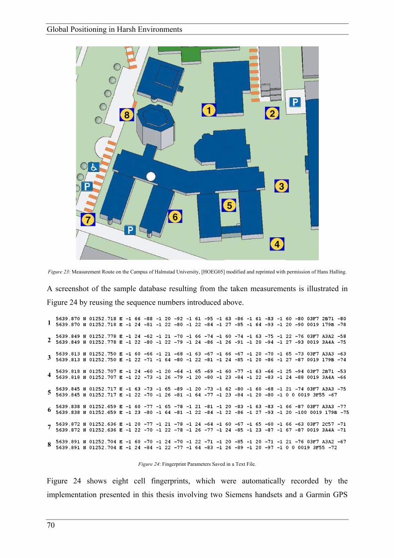
Global Positioning in Harsh Environments
70
Figure 23: Measurement Route on the Campus of Halmstad University, [HOEG05] modified and reprinted with permission of Hans Halling.
A screenshot of the sample database resulting from the taken measurements is illustrated in
Figure 24 by reusing the sequence numbers introduced above.
Figure 24: Fingerprint Parameters Saved in a Text File.
Figure 24 shows eight cell fingerprints, which were automatically recorded by the
implementation presented in this thesis involving two Siemens handsets and a Garmin GPS
1
2
3
4
5
6
7
8

Innovative Approach
71
receiver. The first column contains the sequence numbers of the measurements and the
columns two to five represent the reference positions obtained via GPS. The remaining 21
columns contain GSM information of the serving cells as well as their neighbour cells as
explained in Table 27. The fact that one cell fingerprint contains two identical GPS reference
positions shows that the two mobile phones, which were subscribed to the Swedish GSM
providers Vodafone and Telia, respectively, were used for retrieving the required GSM data at
the same reference position. An explanation of the cell fingerprint obtained by the first
measurement, which is shown in the first two lines of Figure 24, is presented in Table 27.
Description Fingerprint of GSM Provider Telia
Fingerprint of GSM Provider Vodafone
Sequence number of cell fingerprint 1
GPS reference position in ° and ‘ 56° 39.870’ North 012° 52.718’ East
LAC -1 -1
BSIC 66 24 First neighbour cell
Signal level in dBm -88 -81
LAC -1 -1
BSIC 20 22 Second neighbour cell
Signal level in dBm -92 -80
LAC -1 -1
BSIC 61 22 Third neighbour cell
Signal level in dBm -95 -84
LAC -1 -1
BSIC 63 27 Fourth neighbour cell
Signal level in dBm -86 -85
LAC -1 -1
BSIC 61 64 Fifth neighbour cell
Signal level in dBm -83 -93
LAC -1 -1
BSIC 60 20 Sixth neighbour cell
Signal level in dBm -80 -90
LAC 03F7 0019
CI 2B71 179B Serving cell
Signal level in dBm -80 -78
Table 27: Sample Database Entry.
The third line of Table 27 represents the reference position of the cell fingerprint, whereby the
values for the x-coordinate and the y-coordinate are split up into degrees and minutes
according to the description provided in Table 25. However, this separation is not done in the

Global Positioning in Harsh Environments
72
database for reasons of easier processing. The following lines contain GSM information like
signal levels in dBm, BSICs for all neighbour cells as well as LAC, CI and received signal
level for the serving cell. Due to the fact that the parameter LAC is only available for the
serving cell, this value is set to -1 for all neighbour cells within the presented implementation.
As explained in Table 24, the first digit of the GSM parameter BSIC is the provider-
dependent Network Colour Code (NCC). According to Table 27, the Swedish GSM provider
Telia can be identified by an NCC of 6 and Vodafone employs the NCC value 2. Furthermore,
it has to be stated that the second neighbour cell of the Telia record is established by using a
Vodafone base station and that Vodafone also uses a base station of the provider Telia, which
can be seen from the entry representing its fifth neighbour cell. This can be explained by the
common practice of GSM providers to share their base stations within inter-provider
cooperation. As a matter of fact, this decreases the number of base stations available for
fingerprint measurements and increases the importance of the presented approach to involve a
high number of GSM providers into the process of establishing a fingerprint database.
Finally, it has to be stated that the recorded values were verified by comparing them to the
values displayed at the GPS receiver and the values returned and displayed by the Siemens
network monitor installed at the mobile phones.

Future Work
73
5 Future Work
After having decided for database correlation as a complement to GPS within a global
tracking solution, the main aim of the implementation presented in chapter 4 was to prove its
technical feasibility. The information required for GSM cell fingerprints including base
stations of more than one GSM provider is obtainable without any provider cooperation.
Furthermore, the process of collecting fingerprint data could be done in an automated way.
However, the described implementation can only be a starting point for the realisation of an
embedded device that is capable to collect cell fingerprints along routes of great interests
automatically. For instance, enhancing the availability of GPS during the process of
fingerprint collection is one of the problems still to be solved. As a matter of fact, the cell
fingerprints have to contain a reference position even in harsh environments. The benefit of
the solution presented in this thesis is that enhancing the availability of GPS by involving for
example an indoor-capable GPS receiver, map information or speed measurements is less
cost-critical, since these enhancements must only be done for the embedded device collecting
the cell fingerprints. The devices used for the tracking of goods later on just have to be able to
measure GSM and GPS signals employing standard GSM and GPS receivers without the need
of highly developed and costly GPS equipment.
Another critical aspect requiring future research is the timing behaviour of the implementation
during cell-fingerprint collection. If the presented solution should be able to record GSM cell
information while moving at a certain speed, the timing and thus the amount of motion have
to be taken into account in order to obtain unsophisticated position data.
Finally, further investigations about the switching between GSM and GPS positioning, the
benefits of measuring signals from more than one GSM provider, the implementation of an
interpreter for other GSM handsets than those produced by Siemens and an adequate database
correlation algorithm are necessary.

Global Positioning in Harsh Environments
74

Conclusion
75
6 Conclusion
This thesis presents an evaluation of several location estimation technologies as well as a new
positioning approach, which should provide the basis for a world-wide freight-tracking
system.
Several existing positioning methods were assessed concerning the eight criteria positioning
accuracy, world-wide availability, impact on the handset, impact on the existing network,
needed provider cooperation, operating compatibility with underlying technologies, roaming
support in other networks and technology-specific aspects. Further, these methods were
examined regarding their suitability for a globally operable goods-tracking application.
By providing an extensive assessment, it was shown that three approaches, namely indoor
GPS, assisted GPS and the database correlation technique are suitable bases for the realisation
of a global goods-tracking system. Most other technologies could not be taken into
consideration for the new method developed in this project because of knock-out criteria such
as a too big amount of necessary provider cooperation, too complex implementation for a
world-wide deployment or too high adaptation costs for the handsets as well as for the
underlying network. A detailed evaluation summary can be found in subchapter 3.10 of this
thesis.
The decision for the innovative approach yielded a combination of GPS and the database
comparison method, with which cell fingerprint measurements can be performed
automatically involving several GSM providers. A comprehensive description of this newly
developed approach is provided in subsection 4. Finally, a verification of the measured values
has been achieved by comparing them to the values returned by the Siemens network monitor
running at the mobile phones and the reference positions directly displayed by the employed
GPS receiver, respectively. Having provided a valuable basis for the implementation of a
global freight-tracking application by this thesis, problems as the timing behaviour of the
presented approach, the development of an adequate database correlation algorithm, the
enhancement of GPS during fingerprint collections and, finally, the construction of the
proposed embedded device still have to be solved within future research.

Global Positioning in Harsh Environments
76

References
77
References
[3GPP04] 3rd Generation Partnership Project, Technical Specification Group Services and
System Aspects (2004) Functional Stage 2 Description of Location Services
(LCS), Release 6, September 2004.
[AKTU97] Akturan, R. and Vogel, W. J. (1997) “Path Diversity for LEO Satellite-PCS in
the Urban Environment”. Antennas and Propagation, IEEE Transactions on,
Volume 45, Issue 7, pp. 1107-1116, July 1997.
[AROR96] Arora, R. K. (1996) “Low Cost Underlay to GPS for a Metropolitan Area
Geographic Positioning System”. Radar, CIE International Conference of,
Proceedings, pp. 786-788, 8-10 October 1996.
[BENE01] Benedicto, Javier and Ludwig, Daniel (2001) “Galileo Defined: Proposed
Architecture and Services for the new European Satellite Positioning System”.
GPS World, 12(2001)9, pp. 46, 48-49, Eugene, Oregon, September 2001.
[BENE05] Benefon Oyi (2005) “Benefon :: Products :: Benefon Esc!”,
http://www.benefon.com/products/esc (13 January 2005).
[BRAA01a] Braasch, Michael S. (2001) “Performance Comparison of Multipath Mitigating
Receiver Architectures”. Aerospace Conference, IEEE Proceedings, Volume 3,
pp. 1309-1315, 10-17 March 2001.
[BRAA01b] Braasch, M. S. (2001) “Spread-Spectrum Ranging Multipath Model
Validation”. Aerospace and Electronic Systems, IEEE Transactions on,
Volume 37, Issue 1, pp. 298-304, 1 January 2001.
[COOP94] Cooper, S. and Durrant-Whyte, H. (1994) “A Kalman Filter Model for GPS
Navigation of Land Vehicles”. Advanced Robotic Systems and the Real World,
IROS ’94, Proceedings of the IEEE/RSJ/GI International Conference, Volume
1, pp. 157-163, 12-16 September 1994.

Global Positioning in Harsh Environments
78
[CSIC04] Coordination Scientific Information Center (2004) “GLONASS – Global
Navigation Satellite System”, http://www.glonass-center.ru (16 May 2004).
[DIGG01] van Diggelen, Frank (2001) “Global Locate Indoor GPS Chipset & Services”,
ION-GPS 2001, 14th International Technical Meeting of the Satellite Division
of the Institute of Navigation, Salt Palace Convention Center, Salt Lake City,
USA, Utah, September 11-14, 2001.
[DIGG02] van Diggelen, Frank (2002) “Indoor GPS Theory & Implementation”, IEEE
Position, Location & Navigation Symposium, Palm Springs, CA, USA, April
15-18, 2002.
[DJUK01] Djuknic, Goran M. and Richton, Robert E. (2001) “Geolocation and Assisted-
GPS”. Bell Laboratories, Lucent Technology, February 2001.
[DRAN98] Drane, Christopher et al. (1998) “Positioning GSM Telephones”.
Communications Magazine, IEEE, Volume: 36, Issue: 4, April 1998.
[DRUR00] Drury, Gordon, et al. (2000) Reed-Solomon Codes. In: G. Drury et al., Coding
and Modulation for Digital Television. New York, Boston, Dordrecht, London,
Moscow: Kluwer Academic, pp. 126-133.
[EMIL04] EMILY Project Group (2004) ERTICO - Emily Project,
http://www.emilypgm.com (10 November 2004).
[ERIC03] Ericsson AB (2003) “Mobile Positioning Protocol Specification”, Protocol
Specification, Version 5.0, 2003.
[ESA04] Rolfe, Erica et al. (2004) ESA – Navigation, http://www.esa.int (24 May
2004).
[ETSI95] European Telecommunications Standards Institute (1995) “Radio Sub – system
Link Control”, Recommendation GSM 05.08, Version 3.8.0,
http://www.etsi.org, December 1995.

References
79
[ETSI96] European Telecommunications Standards Institute (1996) “Digital Cellular
Telecommunications system (Phase 2+); AT Command Set for GSM Mobile
Equipment (ME)”, Technical Specification GSM 07.07, Version 5.5.0,
http://www.etsi.org, July 1996.
[ETSI98a] European Telecommunications Standards Institute (1998) “Digital Cellular
Telecommunications System (Phase 2+); Use of Data Terminal Equipment -
Data Circuit Terminating Equipment (DTE - DCE) Interface for Short Message
Service (SMS) and Cell Broadcast Service (CBS) ()“, Technical Specification
GSM 07.05, Version 5.5.0, http://www.etsi.org, January 1998.
[ETSI98b] European Telecommunications Standards Institute (1998) “Digital cellular
telecommunications system (Phase 2+); Specification of the SIM application
toolkit for the Subscriber Identity Module - Mobile Equipment (SIM – ME)
interface”, Technical Specification GSM 11.14, Version 5.9.0,
http://www.etsi.org, November 1998.
[ETSI00] European Telecommunications Standards Institute (2000) “Digital cellular
telecommunications system (Phase 2+); Mobile radio interface; Layer 3
specification”, European Telecommunication Standard 300 940, GSM 04.08,
Version 5.12.1, http://www.etsi.org, April 2000.
[ETSI01] European Telecommunications Standards Institute (2001) “Digital cellular
telecommunications system (Phase 2+); Specification of the SIM Application
Toolkit for the Subscriber Identity Module - Mobile Equipment (SIM-ME)
interface”, 3GPP Technical Standard 101 267, TS 11.14, Version 8.9.0,
http://www.etsi.org, December 2001.
[EUCO03] European Communities (2003) EUROPA – Energy and Transport – GALILEO
– Introduction http://europa.eu.int/comm/dgs/energy_transport/galileo/intro/
index_en.htm (26 May 2004).

Global Positioning in Harsh Environments
80
[GARM02] Garmin International, Inc. (2002) “GPS 16/17 Series Technical Specification”.
Revision B, November 2002, http://www.garmin.com (13 January 2004).
[GARM05] Garmin Corp. (2005) Garmin: What is GPS?, http://www.garmin.com/
aboutGPS, (8 January 2005).
[GLOB04] Global Locate Inc. (2004) Global Locate: IndoorGPS™,
http://www.globallocate.com/index.asp?page (10 October 2004).
[HACH03] Hachani, Slim et al. (2003) “Cellular/GNSS Hybrid Module Specification and
Interfaces”, EMILY.IST-2000-26040, Deliverable 9, 9 September 2003.
[HEIN02a] Heinrichs, Günter (2002) “Using of RAKE Receiver Architecture for
Combining GNSS and CDMA Cellular Wireless Location”. Spread Spectrum
Techniques and Applications, IEEE 7th Symposium on, Volume 3, pp. 787-791,
2002.
[HEIN02b] Heinrichs, Günter et al. (2002) “Receiver Architecture Synergies Between
Future GPS/Galileo and UMTS/IMT-2000”. Vehicular Technology
Conference, IEEE 56th, Proceedings, Volume 3, pp. 1602-1606, 24-28.
September 2002.
[HOEG05] Högskolan i Halmstad (2005) Högskolan i Halmstad, http://www.hh.se/
download/Campuskarta/campuskarta041029.pdf (17 January 2005).
[HOFM97] Hofmann-Wellenhof, B. et al. (1997) Global Positioning System – Theory and
Practice. 4th edition. Vienna: Springer-Verlag.
[IEEE00] IEEE (2000) “Global Positioning System – The Newest Utility”. Aerospace
and Electronic Systems Magazine, IEEE, Volume 15, Issue 10, pp. 89-95,
October 2000.
[ISSL03] Issler, Jean-Luc et al. (2003) “Galileo Frequency & Signal Design”. GPS
World, Eugene, Oregon 14(2003)6, pp. 30-37, June 2003.

References
81
[ITUT99] Telecommunication Standardization Sector of International Tele-
communication Union (1999) “Serial Asynchronous Automatic Dialling and
Control”, Series V: Data Communication over the Telephone Network, Control
Procedures, Recommendation V.250, May 1999.
[KAN03] Kan, Kenny Ka Ho et al. (2003) “A Dual-Channel Location Estimation System
for Providing Location Services Based on the GPS and GSM Networks”.
Advanced Information Networking and Applications, 17th International
Conference on, pp. 7-12, 27-29 March 2003.
[KARA95] Karasawa, Y. et al. (1995) “A Propagation Channel Model for Personal
Mobile-satellite services”. Progress of Electromagnetic Research Symposium
of the European Space Agency, pp. 11-15, July 1995.
[KLUK03] Klukas, R. et al. (2003) “GPS Signal Fading Model for Urban Centres”.
Microwaves, Antennas and Propagation, IEE Proceedings, Vol 150, Issue 4,
pp. 245-252, August 2003.
[KUEG99] Kuegler, D. (1999). ”Integration of GPS and Loran-C/Chayka: A European
perspective”, Navigation, 46(1), pp. 1-11.
[KUNC04] Kunczier, Harald and Anegg, Hermann (2004) “Enhanced Cell ID Based
Terminal Location for Urban Area Location Based Applications”. Consumer
Communications and Networking Conference 2004, First IEEE, 5-8 January
2004.
[KVAE04] Kvael, Lars (2004) Northwest European Loran-C System, http://www.nels.org
(13 May 2004).
[LAIT01a] Laitinen, Heikki et al. (2001) “Cellular Location Technology”. Paper about the
project Cellular Network Optimisation Based on Mobile Location published by
CELLO Consortium, Version 007, 25 October 2001.

Global Positioning in Harsh Environments
82
[LAIT01b] Laitinen, Heikki et al. (2001) “Database Correlation Method for GSM
Location”, IEEE VTC 2001 Spring Conference, Rhodes, May 2001.
[LEIC95] Leick, A. (1995) GPS Satellite Surveying. 2nd edition. New York: John Wiley
& Sons Inc.
[LAMA02] LaMance, Jimmy et al. (2002) “Assisted GPS: A Low-Infrastructure
Approach”, GPS World, Vol. 13, No. 3, pp. 46-51.
[LIF02] Location Interoperability Forum Ltd. (2002) “Mobile Location Protocol”, LIF
TS 101 Specification, Version 3.0.0, 6 June 2002.
[LOPE99] Lopes, L. et al. (1999) “GMS Standards Activity on Location”. IEE Colloquim
on Novel Methods of Location and Tracking of Cellular Mobiles and Their
System Applications, London, May 1999.
[MACA00] Macabiau, C. et al. (2000) “N-Multipath Performance of GPS Receivers”.
Position Location and Navigation Symposium, IEEE 2000, pp. 41-48, 13-16
March 2000.
[MACG02] MacGougan, G. et al. (2002) “Degraded GPS Signal Measurements with a
Stand-alone High Sensitivity Receiver”. National Technical Meeting, Institute
of Navigation’s, Proceedings, pp. 191-204, January 2002.
[MART02] Martin-Escalona, Israel et al. (2002) “Delivery of Non-standardized Assistance
Data in E-OTD/GNSS Hybrid Location Systems”. Personal, Indoor and
Mobile Radio Communications, The 13th IEEE International Symposium on,
Volume: 5, 15-18 Sept. 2002.
[MELG94] Melgard, T. E. et al. (1994) “GPS Signal Availability in an Urban Area–
Receiver Performance Analysis”. Position Location and Navigation
Symposium, IEEE, pp. 487-493, 11-15 April 1994.
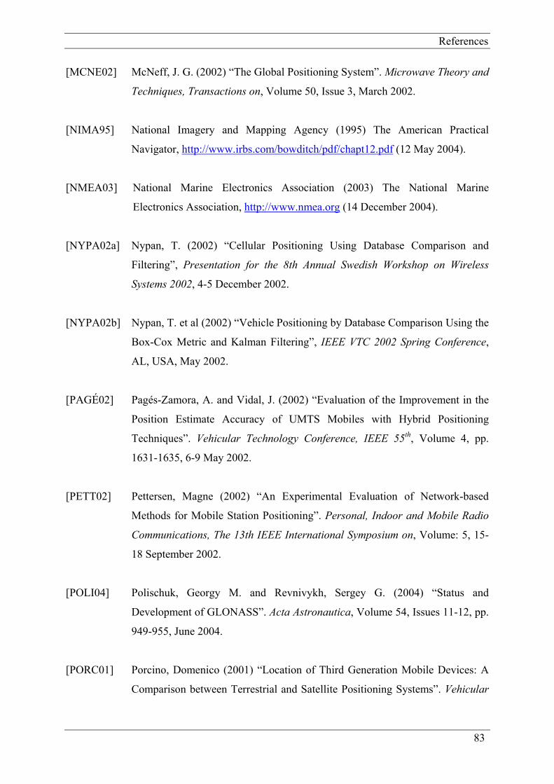
References
83
[MCNE02] McNeff, J. G. (2002) “The Global Positioning System”. Microwave Theory and
Techniques, Transactions on, Volume 50, Issue 3, March 2002.
[NIMA95] National Imagery and Mapping Agency (1995) The American Practical
Navigator, http://www.irbs.com/bowditch/pdf/chapt12.pdf (12 May 2004).
[NMEA03] National Marine Electronics Association (2003) The National Marine
Electronics Association, http://www.nmea.org (14 December 2004).
[NYPA02a] Nypan, T. (2002) “Cellular Positioning Using Database Comparison and
Filtering”, Presentation for the 8th Annual Swedish Workshop on Wireless
Systems 2002, 4-5 December 2002.
[NYPA02b] Nypan, T. et al (2002) “Vehicle Positioning by Database Comparison Using the
Box-Cox Metric and Kalman Filtering”, IEEE VTC 2002 Spring Conference,
AL, USA, May 2002.
[PAGÉ02] Pagés-Zamora, A. and Vidal, J. (2002) “Evaluation of the Improvement in the
Position Estimate Accuracy of UMTS Mobiles with Hybrid Positioning
Techniques”. Vehicular Technology Conference, IEEE 55th, Volume 4, pp.
1631-1635, 6-9 May 2002.
[PETT02] Pettersen, Magne (2002) “An Experimental Evaluation of Network-based
Methods for Mobile Station Positioning”. Personal, Indoor and Mobile Radio
Communications, The 13th IEEE International Symposium on, Volume: 5, 15-
18 September 2002.
[POLI04] Polischuk, Georgy M. and Revnivykh, Sergey G. (2004) “Status and
Development of GLONASS”. Acta Astronautica, Volume 54, Issues 11-12, pp.
949-955, June 2004.
[PORC01] Porcino, Domenico (2001) “Location of Third Generation Mobile Devices: A
Comparison between Terrestrial and Satellite Positioning Systems”. Vehicular

Global Positioning in Harsh Environments
84
Technology Conference, VTC 2001 Spring, IEEE VTS 53rd, Volume: 4, 6-9
May 2001.
[PROC01] Proc, Jerry (2001) Loran-C Introduction, http://webhome.idirect.com/~jproc/
hyperbolic/loran_c.html (16 May 2004).
[ROOS02] Roos, Teemu (2002) “A Statistical Modeling Approach to Location
Estimation”. Mobile Computing, IEEE Transactions on, Volume: 1, Issue: 1,
January-March 2002.
[RUUT98] Ruutu, V. et al. (1998) “Mobile Phone Location in Dedicated and Idle Modes”.
Personal, Indoor and Mobile Radio Communications, The Ninth IEEE
International Symposium on, Volume 1, pp. 456-460, 8-11 September 1998.
[SCHM03] Schmitz, Heiko et al. (2003) “ A New Method for Positioning of Mobile Users
by Comparing a Time Series of Measured Reception Power Levels with
Predictions”. Vehicular Technology Conference, The 57th, VTC 2003 Spring,
IEEE Semiannual, Volume: 3, 22-25 April 2003.
[SHAO02] Shaojun Feng and Choi Look Law (2002) “Assisted GPS and its Impact on
Navigation in Intelligent Transportation Systems”. Intelligent Transportation
Systems, IEEE 5th International Conference on, Proceedings, pp. 926-931, 3-6
September 2002.
[SHAW04] Shaw, M. (2004) “Modernization of the Global Positioning System”. Acta
Austronautica, Volume 54, pp. 943-947, 2004.
[SIEM02] Siemens, Inc (2002) “Siemens Mobile Phones – AT command set for L55
Siemens mobile phones and modems”. Reference Manual, Version 2.1, 1
August 2002, http://communications.siemens.com (12 January 2005).
[SIRF04] SiRF Technology, Inc. (2004) GPS Technology – SiRF, GPS Technology
White Paper, http://www.skyaid.org/LifeWatch/sIRF_gps.htm (19 October
2004).

References
85
[SILV96] Silventoinen, Marko I. and Rantalainen, Timo (1996) “Mobile Station
Emergency Locating in GSM”. Personal Wireless Communications, IEEE
International Conference on, 19-21 February 1996.
[SNAP03] SnapTrack Incorporated (2003) “Location Technologies for GSM, GPRS and
UMTS Networks”, White Paper, SnapTrack Incorporated, January 2003.
[SPIR00] Spirito, Maurizio A. (2000) “Mobile Station Location with Heterogeneous
Data”. Vehicular Technology Conference, VTC 2000 Fall, IEEE VTS 52nd,
Volume: 4, 24-28 September 2000.
[SPIR01] Spirito, Maurizio A. et al. (2001) “Experimental Performance of Methods to
Estimate the Location of Legacy Handsets in GSM”. Vehicular Technology
Conference, VTC 2001 Fall, IEEE VTS 54th, Volume: 4, 7-11 October 2001.
[SUN04] Sun Microsystems, Inc. (2004) Java Technology, http://java.sun.com (7
December 2004).
[TUDE99] Technical University Delft (1999) The Eurofix Internet Pages,
http://www.eurofix.tudelft.nl (30 May 2004).
[UNIT04] United Nations Foundation (2004) UN Atlas of the Oceans,
http://www.oceansatlas.com/unatlas/uses/transportation_telecomm/maritime_tr
ans/nav/navigation.htm (27 May 2004).
[USCG03] U.S. Coast Guard Navigation Center (2002) Loran-C General Information,
http://www.navcen.uscg.gov/loran/default.htm (16 May 2004).
[WANG00] Wang, S. S. et al. (2000) “E-911 Location Standards and Location Commercial
Services”. Emerging Technologies Symposium: Broadband, Wireless Internet
Access, pp. 1-5, 10-11 April 2000.

Global Positioning in Harsh Environments
86
[WILL98] van Willigen, et al. (1998) “EUROFIX: Definition and Current Status”.
Position Location and Navigation Symposium, IEEE 1998, 20-23 April 1998.

Appendix A: Mobile Protocols
87
Appendix A: Mobile Protocols
For the implementation of the innovative approach described in chapter 4, two mobile
protocols have to be investigated because of their importance for the location estimation
system as a whole. The first one is the Mobile Positioning Protocol (MPP), which is used to
interface a Mobile Positioning System (MPS), and secondly that is the Mobile Location
Protocol (MLP), which enables location applications to query position information from a
GMPC entity in a wireless network. The practical application scenario of the two protocols is
depicted in Figure 25.
Figure 25: Practical Application Scenario of MPP and MLP.
Mobile Positioning Protocol As mentioned in the protocol version 5.0 specification [ERIC03], MPP is employed to
interface a Mobile Positioning System, meaning that this application-level protocol makes it
possible to request the position of a mobile station.
MPP operates on top of HTTP 1.0 and HTTP 1.1, respectively, which are request-response
type protocols. This model implies a communication between a server and a client, which are
called GMPC (Gateway Mobile Positioning Centre) and LCS (Location Service) client,
respectively. The communication itself can be performed over two ports, one serving for
insecure messaging and one for Secure Socket Layer (SSL) encrypted communication.
The request sent by the LCS client must contain the entity-headers Content-Type and Content-
Length, while the message body should comprise the position request itself in XML format.
After this request has been sent by the LCS client, the GMPC answers with a successful
response or with an error message, which can either concern HTTP or MPP what presumes
the client to be prepared for both protocol error messages.
Within the request, two QoS parameters for the response time and the horizontal accuracy can
be specified, which directly affect the overall accuracy of the positioning process.
Furthermore, the way, in which the response shall be presented, can be submitted within the

Global Positioning in Harsh Environments
88
request, which determines the coordinate system, the geodetic datum and the format of the
response.
A successful answer means that it has correct syntax and it has passed all authority checks. A
response is considered unsuccessful, if the request is rejected by the GMPC what happens as
soon as at least one of the criteria mentioned above is not fulfilled.
A further and more detailed description of the elements of the request and the response
messages, position areas, error codes as well as request and response examples of MPP can be
found in [ERIC03].
Mobile Location Protocol As stated in the version 3.0.0 protocol specification [LIF02], MLP enables location
applications to query position information from a wireless network independently of the
underlying positioning and wireless technologies. MLP can be seen as the interface between a
location-based application and a location server. The application-layer protocol, which
operates on HTTP and SSL, is syntactically based on XML. Figure 26 depicts the protocol
stack of MLP.
Figure 26: MLP Protocol Stack.
The Transport Layer of the protocol stack determines, over which protocol the XML content
is transmitted. The Element Layer defines all common elements, which are used by the
services of the uppermost layer. Such elements are e.g. Location Element Definitions, Quality
of Position Element Definitions and several more. The Service Layer comprises the actual
services provided by the MLP framework, which can divided in Basic MLP Services and
Advanced MLP Services. The uppermost layer again comprises two sublayers. Firstly, these
are the common elements used by all services and secondly, the actual services are defined in
SLIS ELIS SLRS ELRS TLRS Svc1 Svc2 … Svcn
Basic Common Elements Advanced Common Elements …
Core Location Elements
Transport Layer Mapping (HTTP, WSP, SOAP, …)
Service Layer
Element Layer
Transport Layer
Basic MLP Services
Advanced MLP Services
Other MLP Services

Appendix A: Mobile Protocols
89
the topmost layer. Using such a service presumes that a message contains two main parts, a
context or a header part and a body part. The header consists of subclient elements, which
identify the ASPs, resellers and portals in the sequence of service providers as well as the
sessionid element representing the current session between the location server and the LCS
client.
The body part of the message comprises the request and the answer, respectively and can use
several services, which have already been illustrated in the protocol stack. In the following
subsections, these services are particularly described.
SLIS
The Standard Location Immediate Service (SLIS) is a standard location service for simply
querying the location of a mobile station. This service is used if a response to a location
request is needed immediately, meaning within a certain period of time. The extended service
offers several formats for the location response as well as parameters for QoS, location type
and priority issues.
ELIS
The Emergency Location Immediate Service (ELIS) is used to obtain a mobile user’s position
in the special case that this user has initiated an emergency call what implies the necessity for
an immediate answer.
SLRS
The Standard Location Report Service (SLRS) is employed when a mobile subscriber wants
to convey the MS location to the LCS client what is done by the location server. The address
of the application to be contacted should be defined by the MS or within the location server.
ELRS
The Emergency Location Reporting Service is used if the network automatically initiates an
emergency call when a user originates an emergency call. The application, to which the report
should be sent, as well as the required geographical format are defined in the location server.
TLRS
The Triggered Location Report Service (TLRS) is used when a mobile station’s position
should be reported at occurrences of certain events or in a periodic time interval and therefore
serves for tracking a user’s positions. Following [3GPP04], such events can be UE available
and Change of Area. The first one occurs if the MSC/SGSN (Mobile Switching Centre/
Serving GPRS Support Node) has established a connection to the mobile station. The second

Global Positioning in Harsh Environments
90
event means that the user has entered or left a pre-defined geographical area. In future
specifications of the protocols, several other events like the FriendFinder application are
planned to be included.
Additionally to these services, a General Error Message (GEM) is defined, which is returned
if an LCS client has tried to invoke a service that is not defined in the specification.
An essential aspect to mention in connection with MLP is the protocol’s extension
mechanism, which is the result of a very thought ahead development. This mechanism implies
separate Document Type Definitions (DTDs) that are used by all messages have been defined
in order to facilitate their re-use. Furthermore, new messages can easily be added to the
protocol by defining a “%extension.message”-parameter and finally, new parameters can
easily be inserted into existing messages by the “%extension.param”-parameter, which should
contain a vendor-specific prefix in order to ensure unambiguity. [LIF02]
A more detailed description of the elements, the structure, error mappings and the layer
definitions can be found in [LIF02].