global positioning system gps) satellites broadcast ... _stas_ gp… · global positioning system...
TRANSCRIPT
Global Positioning System (GPS) satellites broadcast microwave signals to enable GPS receivers on or near the
Earth's surface to determine location and time and derive velocity. The GPS system itself is operated by the U.S.
Department of Defense (DoD) for use by both the military and the general public.
GPS signals include ranging signals, used to measure the distance to the satellite, and navigation messages. The
navigation messages include ephemeris data, used to calculate the position of each satellite in orbit, and information
about the time and status of the entire satellite constellation, called the almanac.
There are four signals available for civilian use. In order of date of introduction, these are: L1 C/A, L2C, L5 and
L1C.[1] L1 C/A is also called the legacy signal and is broadcast by all satellites. The other signals are called
modernized signals and are not broadcast by all satellites. In addition, there are restricted signals, also broadcast to
the general public, but whose encoding is secret and are intended to be used only by authorized parties. Nonetheless,
some limited use of restricted signals can be made by civilians without access to the secret encoding details; this is
called codeless and semi-codeless access, and is officially supported.[2]
The interface to the User Segment (GPS receivers) is described in the Interface Control Documents (ICD)
(http://www.gps.gov/technical/icwg/). The format of civilian signals is described in the Interface Specification (IS)
which is a subset of the ICD.
Common characteristicsLegacy GPS signals
Coarse/acquisition codePrecision codeNavigation message
TimeAlmanacStructure of subframes 4 and 5
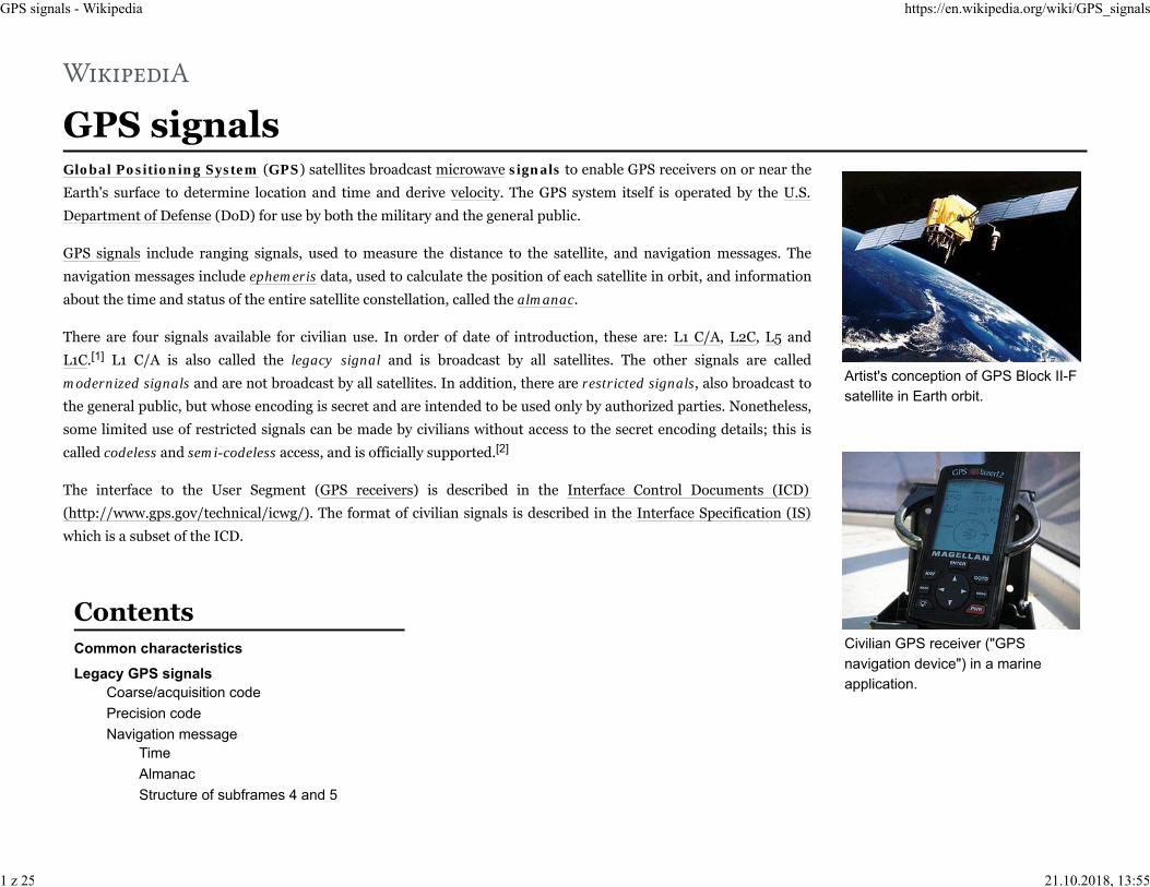
Artist's conception of GPS Block II-Fsatellite in Earth orbit.
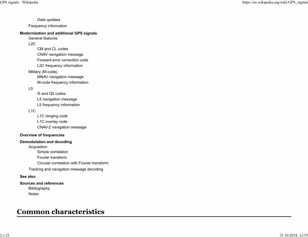
Civilian GPS receiver ("GPSnavigation device") in a marineapplication.
GPS signals - Wikipedia https://en.wikipedia.org/wiki/GPS_signals
1 z 25 21.10.2018, 13:55
Data updatesFrequency information
Modernization and additional GPS signalsGeneral featuresL2C
CM and CL codesCNAV navigation messageForward error correction codeL2C frequency information
Military (M-code)MNAV navigation messageM-code frequency information
L5I5 and Q5 codesL5 navigation messageL5 frequency information
L1CL1C ranging codeL1C overlay codeCNAV-2 navigation message
Overview of frequenciesDemodulation and decoding
AcquisitionSimple correlationFourier transformCircular correlation with Fourier transform
Tracking and navigation message decoding
See alsoSources and references
BibliographyNotes
GPS signals - Wikipedia https://en.wikipedia.org/wiki/GPS_signals
2 z 25 21.10.2018, 13:55

The GPS satellites (called space vehicles in the GPS interface specification documents) transmit simultaneously several ranging codes and navigation data using
binary phase-shift keying (BPSK). Only a limited number of central frequencies are used; satellites using the same frequency are distinguished by using different
ranging codes; in other words, GPS uses code division multiple access. The ranging codes are also called chipping codes (in reference to CDMA/DSSS),
pseudorandom noise and pseudorandom binary sequences (in reference to the fact that it is predictable, but statistically it resembles noise).
Some satellites transmit several BPSK streams at the same frequency in quadrature, in a form of quadrature amplitude modulation. However, unlike typical
QAM systems where a single bit stream is split in two half-symbol-rate bit streams to improve spectral efficiency, in GPS signals the in-phase and quadrature
components are modulated by separate (but functionally related) bit streams.
Satellites are uniquely identified by a serial number called space vehicle number (SVN) which does not change during its lifetime. In addition, all operating
satellites are numbered with a space vehicle identifier (SV ID) and pseudorandom noise number (PRN number) which uniquely identifies the ranging codes that
a satellite uses. There is a fixed one-to-one correspondence between SV identifiers and PRN numbers described in the interface specification.[3] Unlike SVNs, the
SV ID/PRN number of a satellite may be changed (also changing the ranging codes it uses). At any point in time, any SV ID/PRN number is in use by at most a
single satellite. A single SV ID/PRN number may have been used by several satellites at different points in time and a single satellite may have used different SV
ID/PRN numbers at different points in time. The current SVNs and PRN numbers for the GPS constellation may be found at NAVCEN
(http://www.navcen.uscg.gov/?Do=constellationStatus).
The original GPS design contains two ranging codes: the coarse/acquisition (C/A) code, which is freely available to the public, and the restricted precision (P)
code, usually reserved for military applications.
The C/A PRN codes are Gold codes with a period of 1023 chips transmitted at 1.023 Mbit/s, causing the code to repeat every 1 millisecond. They are combined
with a navigation message using exclusive or and the resulting bit stream is used for modulation as previously described. These codes only match up, or strongly
autocorrelate when they are almost exactly aligned. Each satellite uses a unique PRN code, which does not correlate well with any other satellite's PRN code. In
other words, the PRN codes are highly orthogonal to one another. The 1 ms period of the C/A code corresponds to a 299,8 km symbol length, and the alignment
of the C/A bit stream resolves phase information to a precision of 293 m.
The C/A codes are generated by combining (using "exclusive or") 2-bit streams generated by maximal period 10 stage linear feedback shift registers (LFSR).
Different codes are obtained by selectively delaying one of those bit streams. Thus:
Coarse/acquisition code
GPS signals - Wikipedia https://en.wikipedia.org/wiki/GPS_signals
3 z 25 21.10.2018, 13:55

where:
is the code with PRN number . is the output of the first LFSR whose generator polynomial is , and initial state is 11111111112. is the output of the second LFSR whose generator polynomial is and initial state is
also 11111111112. is a delay (by an integer number of periods) specific to each PRN number ; it is designated in the GPS interface
specification.[3]
is exclusive or.
The arguments of the functions therein are the number of bits or chips since their epochs, starting at 0. The epoch of the LFSRs is the point at which they are at
the initial state; and for the overall C/A codes it is the start of any UTC second plus any integer number of milliseconds. The output of LFSRs at negative
arguments is defined consistent with the period which is 1,023 chips (this provision is necessary because may have a negative argument using the above
equation).
The delay for PRN numbers 34 and 37 is the same; therefore their C/A codes are identical and are not transmitted at the same time[4] (it may make one or both
of those signals unusable due to mutual interference depending on the relative power levels received on each GPS receiver).
The P-code is also a PRN; however, each satellite's P-code PRN code is 6.187104 · 1012 bits long (773,388 GByte) and only repeats once a week (it is transmitted
at 10.23 Mbit/s). The extreme length of the P-code increases its correlation gain and eliminates any range ambiguity within the Solar System. However, the code
is so long and complex it was believed that a receiver could not directly acquire and synchronize with this signal alone. It was expected that the receiver would
first lock onto the relatively simple C/A code and then, after obtaining the current time and approximate position, synchronize with the P-code.
Whereas the C/A PRNs are unique for each satellite, the P-code PRN is actually a small segment of a master P-code approximately 2.35 · 1014 bits in length
(235,000,000,000,000 bits, ~26.716 terabytes) and each satellite repeatedly transmits its assigned segment of the master code.
To prevent unauthorized users from using or potentially interfering with the military signal through spoofing, it was decided to encrypt the P-code. To that end
the P-code was modulated with the W-code, a special encryption sequence, to generate the Y-code. The Y-code is what the satellites have been transmitting since
the anti-spoofing module was set to the "on" state. The encrypted signal is referred to as the P(Y)-code.
The details of the W-code are kept secret, but it is known that it is applied to the P-code at approximately 500 kHz,[5] which is a slower rate than that of the
P-code itself by a factor of approximately 20. This has allowed companies to develop semi-codeless approaches for tracking the P(Y) signal, without knowledge
of the W-code itself.
Precision code
GPS signals - Wikipedia https://en.wikipedia.org/wiki/GPS_signals
4 z 25 21.10.2018, 13:55

In addition to the PRN ranging codes, a receiver needs to know detailed information about each satellite's
position and the network. The GPS design has this information modulated on top of both the C/A and P(Y)
ranging codes at 50 bit/s and calls it the navigation message. The navigation message format described in
this section is called LNAV data (for legacy navigation).
The navigation message conveys information which can be classified in 3 broad areas:
The GPS date and time, plus the satellite's status and an indication of its health.The ephemeris: orbital information which allows the receiver to calculate the position of the satellite.Each satellite transmits its own ephemeris.The almanac data: contains information and status concerning all the satellites; each satellite transmitsalmanac data for several (possibly all) satellites, depending on which PRN numbers are in use.
Whereas ephemeris information is highly detailed and considered valid for no more than four hours,
almanac information is more general and is considered valid for up to 180 days. The almanac assists the
receiver in determining which satellites to search for, and once the receiver picks up each satellite's signal in
turn, it then downloads the ephemeris data directly from that satellite. A position fix using any satellite can
not be calculated until the receiver has an accurate and complete copy of that satellite's ephemeris data. If
the signal from a satellite is lost while its ephemeris data is being acquired, the receiver must discard that
data and start again.
The navigation message consists of 1,500 bit long frames. Each frame consists of 5 subframes of 300 bits, numbered 1 to 5. In turn each subframe consists of 10
words of 30 bit each and requires 6 seconds to transmit. Each subframe has the GPS time. Subframe 1 contains the GPS date (week number) and information to
correct the satellite's time to GPS time, plus satellite status and health. Subframes 2 and 3 together contain the transmitting satellite's ephemeris data.
Subframes 4 and 5 contain components of the almanac but each frame contains only 1/25th of the complete almanac; a receiver must process 25 whole frames
worth of data to retrieve the entire 15,000 bit almanac message. At this rate, 12.5 minutes are required to receive the entire almanac from a single satellite. Each
of the 25 versions of frames 4 and 5 is called a page and they are numbered 1 to 25.
Frames begin and end at the start/end of week plus an integer multiple of 30 seconds. At start/end of week the cycling between pages is reset to page 1.[6]
There are two navigation message types: LNAV-L is used by satellites with PRN numbers 1 to 32 (called lower PRN numbers) and LNAV-U is used by satellites
with PRN numbers 33 to 63 (called upper PRN numbers).[7] The 2 types use very similar formats. Subframes 1 to 3 are the same[8] while subframes 4 and 5 use
almost the same format. Both message types contain almanac data for all satellites using the same navigation message type, but not the other type.
Each subframe begins with a Telemetry Word (TLM), which enables the receiver to detect the beginning of a subframe and determine the receiver clock time at
which the navigation subframe begins. The next word is the handover word (HOW), which gives the GPS time (actually the time when the first bit of the next
Navigation message
GPS message format
Sub-frame Page Description
11–2 Telemetry and handover words
(TLM and HOW)
3–10 Satellite clock,GPS time relationship
2–31–2 Telemetry and handover words
(TLM and HOW)
3–10 Ephemeris(precise satellite orbit)
4–5
1–2 Telemetry and handover words(TLM and HOW)
3–10Almanac component(satellite network synopsis,error correction)
GPS signals - Wikipedia https://en.wikipedia.org/wiki/GPS_signals
5 z 25 21.10.2018, 13:55

subframe will be transmitted) and identifies the specific subframe within a complete frame.[9][10] The remaining eight words of the subframe contain the actual
data specific to that subframe. Each word includes 6 bits of parity generated using an algorithm based on Hamming codes, which take into account the 24 non-
parity bits of that word and the last 2 bits of the previous word.
After a subframe has been read and interpreted, the time the next subframe was sent can be calculated through the use of the clock correction data and the
HOW. The receiver knows the receiver clock time of when the beginning of the next subframe was received from detection of the Telemetry Word thereby
enabling computation of the transit time and thus the pseudorange. The receiver is potentially capable of getting a new pseudorange measurement at the
beginning of each subframe or every 6 seconds.
GPS time is expressed with a resolution of 1.5 seconds as a week number and a time of week count (TOW).[11] Its zero point (week 0, TOW 0) is defined to be
1980-01-06T00:00Z. The TOW count is a value ranging from 0 to 403,199 whose meaning is the number of 1.5 second periods elapsed since the beginning of the
GPS week. Expressing TOW count thus requires 19 bits (219 = 524,288). GPS time is a continuous time scale in that it does not include leap seconds; therefore
the start/end of GPS weeks may differ from that of the corresponding UTC day by an integer number of seconds.
In each subframe, each hand-over word (HOW) contains the most significant 17 bits of the TOW count corresponding to the start of the next following
subframe.[12] Note that the 2 least significant bits can be safely omitted because one HOW occurs in the navigation message every 6 seconds, which is equal to
the resolution of the truncated TOW count thereof. Equivalently, the truncated TOW count is the time duration since the last GPS week start/end to the
beginning of the next frame in units of 6 seconds.
Each frame contains (in subframe 1) the 10 least significant bits of the corresponding GPS week number.[13] Note that each frame is entirely within one GPS
week because GPS frames do not cross GPS week boundaries.[14] Since rollover occurs every 1,024 GPS weeks (approximately every 19.6 years; 1,024 is 210), a
receiver that computes current calendar dates needs to deduce the upper week number bits or obtain them from a different source. One possible method is for
the receiver to save its current date in memory when shut down, and when powered on, assume that the newly decoded truncated week number corresponds to
the period of 1,024 weeks that starts at the last saved date. This method correctly deduces the full week number if the receiver is never allowed to remain shut
down (or without a time and position fix) for more than 1,024 weeks (~19.6 years).
The almanac consists of coarse orbit and status information for each satellite in the constellation, an ionospheric model, and information to relate GPS derived
time to Coordinated Universal Time (UTC). Each frame contains a part of the almanac (in subframes 4 and 5) and the complete almanac is transmitted by each
satellite in 25 frames total (requiring 12.5 minutes).[15] The almanac serves several purposes. The first is to assist in the acquisition of satellites at power-up by
allowing the receiver to generate a list of visible satellites based on stored position and time, while an ephemeris from each satellite is needed to compute
position fixes using that satellite. In older hardware, lack of an almanac in a new receiver would cause long delays before providing a valid position, because the
Time
Almanac
GPS signals - Wikipedia https://en.wikipedia.org/wiki/GPS_signals
6 z 25 21.10.2018, 13:55

search for each satellite was a slow process. Advances in hardware have made the acquisition process much faster, so not having an almanac is no longer an
issue. The second purpose is for relating time derived from the GPS (called GPS time) to the international time standard of UTC. Finally, the almanac allows a
single-frequency receiver to correct for ionospheric delay error by using a global ionospheric model. The corrections are not as accurate as GNSS augmentation
systems like WAAS or dual-frequency receivers. However, it is often better than no correction, since ionospheric error is the largest error source for a single-
frequency GPS receiver.
LNAV-L frames 4 and 5[16]
Sub-frame Page Description
4
1–2, 6, 11–12,16, 19–24 Reserved
2(?)–5, 7–10 Almanac data for SV 25–32
13 Navigation messagecorrection table (NMCT)
14–15 Reserved for system use
17 Special messages
18 Ionospheric correction dataand UTC
25 A-S flags for SV 1–32,health info. for SV 25–32
51–24 Almanac data for SV 1–24
25 Health info. for SV 1–24almanac reference time
LNAV-U frames 4 and 5[17]
Sub-frame Page Description
4
1, 6, 10–12,16, 19–24 Reserved
2–5, 7–9 Almanac data for SV 89–95
13 Navigation messagecorrection table (NMCT)
14–15 Reserved for system use
17 Special messages
18 Ionospheric correction dataand UTC
25 A-S flags for PRN numbers 33–63,health info. for SV 89–95
51–24 Almanac data for SV 65–88
25 Health info. for SV 65–88almanac reference time
Satellite data is updated typically every 24 hours, with up to 60 days data loaded in case there is a disruption in the ability to make updates regularly. Typically
the updates contain new ephemerides, with new almanacs uploaded less frequently. The Control Segment guarantees that during normal operations a new
almanac will be uploaded at least every 6 days.
Structure of subframes 4 and 5
Data updates
GPS signals - Wikipedia https://en.wikipedia.org/wiki/GPS_signals
7 z 25 21.10.2018, 13:55

Satellites broadcast a new ephemeris every two hours. The ephemeris is generally valid for 4 hours, with provisions for updates every 4 hours or longer in non-
nominal conditions. The time needed to acquire the ephemeris is becoming a significant element of the delay to first position fix, because as the receiver
hardware becomes more capable, the time to lock onto the satellite signals shrinks; however, the ephemeris data requires 18 to 36 seconds before it is received,
due to the low data transmission rate.
For the ranging codes and navigation message to travel from the satellite to the receiver, they must be
modulated onto a carrier wave. In the case of the original GPS design, two frequencies are utilized; one
at 1575.42 MHz (10.23 MHz × 154) called L1; and a second at 1227.60 MHz (10.23 MHz × 120), called
L2.
The C/A code is transmitted on the L1 frequency as a 1.023 MHz signal using a bi-phase shift keying
(BPSK) modulation technique. The P(Y)-code is transmitted on both the L1 and L2 frequencies as a
10.23 MHz signal using the same BPSK modulation, however the P(Y)-code carrier is in quadrature
with the C/A carrier (meaning it is 90° out of phase).
Besides redundancy and increased resistance to jamming, a critical benefit of having two frequencies
transmitted from one satellite is the ability to measure directly, and therefore remove, the ionospheric
delay error for that satellite. Without such a measurement, a GPS receiver must use a generic model or
receive ionospheric corrections from another source (such as the Wide Area Augmentation System or WAAS). Advances in the technology used on both the GPS
satellites and the GPS receivers has made ionospheric delay the largest remaining source of error in the signal. A receiver capable of performing this
measurement can be significantly more accurate and is typically referred to as a dual frequency receiver.
Having reached full operational capability on July 17, 1995[18] the GPS system had completed its original design goals. However, additional advances in
technology and new demands on the existing system led to the effort to "modernize" the GPS system. Announcements from the Vice President and the White
House in 1998 heralded the beginning of these changes and in 2000, the U.S. Congress reaffirmed the effort, referred to as GPS III.
The project involves new ground stations and new satellites, with additional navigation signals for both civilian and military users, and aims to improve the
accuracy and availability for all users. A goal of 2013 has been established with incentives offered to the contractors if they can complete it by 2011.
Frequency information
GPS broadcast signal.
General features
GPS signals - Wikipedia https://en.wikipedia.org/wiki/GPS_signals
8 z 25 21.10.2018, 13:55
Modernized GPS civilian signals have two general improvements over their legacy counterparts: a dataless
acquisition aid and forward error correction (FEC) coding of the NAV message.
A dataless acquisition aid is an additional signal, called a pilot carrier in some cases, broadcast alongside the data
signal. This dataless signal is designed to be easier to acquire than the data encoded and, upon successful
acquisition, can be used to acquire the data signal. This technique improves acquisition of the GPS signal and
boosts power levels at the correlator.
The second advancement is to use forward error correction (FEC) coding on the NAV message itself. Due to the
relatively slow transmission rate of NAV data (usually 50 bits per second), small interruptions can have
potentially large impacts. Therefore, FEC on the NAV message is a significant improvement in overall signal
robustness.
One of the first announcements was the addition of a new civilian-use signal, to be transmitted on a frequency
other than the L1 frequency used for the coarse/acquisition (C/A) signal. Ultimately, this became the L2C signal,
so called because it is broadcast on the L2 frequency. Because it requires new hardware on board the satellite, it is
only transmitted by the so-called Block IIR-M and later design satellites. The L2C signal is tasked with improving accuracy of navigation, providing an easy to
track signal, and acting as a redundant signal in case of localized interference.
Unlike the C/A code, L2C contains two distinct PRN code sequences to provide ranging information; the civil-moderate code (called CM), and the civil-long
length code (called CL). The CM code is 10,230 bits long, repeating every 20 ms. The CL code is 767,250 bits long, repeating every 1,500 ms. Each signal is
transmitted at 511,500 bits per second (bit/s); however, they are multiplexed together to form a 1,023,000-bit/s signal.
CM is modulated with the CNAV Navigation Message (see below), whereas CL does not contain any modulated data and is called a dataless sequence. The long,
dataless sequence provides for approximately 24 dB greater correlation (~250 times stronger) than L1 C/A-code.
When compared to the C/A signal, L2C has 2.7 dB greater data recovery and 0.7 dB greater carrier-tracking, although its transmission power is 2.3 dB weaker.
The civil-moderate and civil-long ranging codes are generated by a modular LFSR which is reset periodically to a predetermined initial state. The period of the
CM and CL is determined by this resetting and not by the natural period of the LFSR (as is the case with the C/A code). The initial states are designated in the
interface specification and are different for different PRN numbers and for CM/CL. The feedback polynomial/mask is the same for CM and CL. The ranging
codes are thus given by:
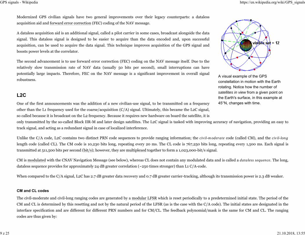
A visual example of the GPSconstellation in motion with the Earthrotating. Notice how the number ofsatellites in view from a given point onthe Earth's surface, in this example at45°N, changes with time.
L2C
CM and CL codes
GPS signals - Wikipedia https://en.wikipedia.org/wiki/GPS_signals
9 z 25 21.10.2018, 13:55

where:
and are the ranging codes for PRN number and their arguments are the integer number of chips elapsed (starting at0) since start/end of GPS week, or equivalently since the origin of the GPS time scale (see § Time).
is the output of the LFSR when initialized with initial state after being clocked times. and are the initial states for CM and CL respectively. for PRN number .
is the remainder of division operation. is the integer number of CM and CL chip periods since the origin of GPS time or equivalently, since any GPS second (starting
from 0).
The initial states are described in the GPS interface specification as numbers expressed in octal following the convention that the LFSR state is interpreted as the
binary representation of a number where the output bit is the least significant bit, and the bit where new bits are shifted in is the most significant bit. Using this
convention, the LFSR shifts from most significant bit to least significant bit and when seen in big endian order, it shifts to the right. The states called final statein the IS are obtained after 10 229 cycles for CM and after 767 249 cycles for LM (just before reset in both cases).
The feedback bit mask is 1001001010010010101001111002. Again with the convention that the least significant bit is the output bit of the LFSR and the most
significant bit is the shift-in bit of the LFSR, 0 means no feedback into that position, and 1 means feedback into that position.
The CNAV data is an upgraded version of the original NAV navigation message. It contains higher precision
representation and nominally more accurate data than the NAV data. The same type of information (time, status,
ephemeris, and almanac) is still transmitted using the new CNAV format; however, instead of using a frame /
subframe architecture, it uses a new pseudo-packetized format made of 12-second 300-bit messages analogous to
LNAV frames. While LNAV frames have a fixed information content, CNAV messages may be of one of several
defined types. The type of a frame determines its information content. Messages do not follow a fixed schedule
regarding which message types will be used, allowing the Control Segment some versatility. However, for some
message types there are lower bounds on how often they will be transmitted.
In CNAV, at least 1 out of every 4 packets are ephemeris data and the same lower bound applies for clock data
packets.[22] The design allows for a wide variety of packet types to be transmitted. With a 32-satellite constellation,
and the current requirements of what needs to be sent, less than 75% of the bandwidth is used. Only a small fraction
of the available packet types have been defined; this enables the system to grow and incorporate advances without
CNAV navigation message
Message structure(common fields)[19]
Bits[20] Information
1–8 Preamble
9–14 PRN of transmitting satellite
15–20 Message type ID
21–37 Truncated TOW count[21]
38 Alert flag
277–300 Cyclic redundancy check
GPS signals - Wikipedia https://en.wikipedia.org/wiki/GPS_signals
10 z 25 21.10.2018, 13:55

breaking compatibility.
There are many important changes in the new CNAV message:
It uses forward error correction (FEC) provided by a rate 1/2 convolutional code, so while thenavigation message is 25-bit/s, a 50-bit/s signal is transmitted.Messages carry a 24-bit CRC, against which integrity can be checked.The GPS week number is now represented as 13 bits, or 8192 weeks, and only repeats every 157.0years, meaning the next return to zero won't occur until the year 2137. This is longer compared tothe L1 NAV message's use of a 10-bit week number, which returns to zero every 19.6 years.There is a packet that contains a GPS-to-GNSS time offset. This allows better interoperability withother global time-transfer systems, such as Galileo and GLONASS, both of which are supported.The extra bandwidth enables the inclusion of a packet for differential correction, to be used in asimilar manner to satellite based augmentation systems and which can be used to correct the L1NAV clock data.Every packet contains an alert flag, to be set if the satellite data can not be trusted. This meansusers will know within 12 seconds if a satellite is no longer usable. Such rapid notification isimportant for safety-of-life applications, such as aviation.Finally, the system is designed to support 63 satellites, compared with 32 in the L1 NAV message.
CNAV messages begin and end at start/end of GPS week plus an integer multiple of 12 seconds.[23] Specifically, the beginning of the first bit (with convolution
encoding already applied) to contain information about a message matches the aforesaid synchronization. CNAV messages begin with an 8-bit preamble which
is a fixed bit pattern and whose purpose is to enable the receiver to detect the beginning of a message.
The convolutional code used to encode CNAV is described by:
where:
and are the unordered outputs of the convolutional encoder is the raw (non FEC encoded) navigation data, consisting of the simple concatenation of the 300-bit messages. is the integer number of non FEC encoded navigation data bits elapsed since an arbitrary point in time (starting at 0).
Message types
Type ID Description
10–11 Ephemeris and health
12, 31, 37 Almanac parameters
13–14, 34 Differential correction
15, 36 Text messages
30 Ionospheric and group delay correction
32 Earth orientation parameters
33 UTC parameters
35 GPS/GNSS time offset
Forward error correction code
GPS signals - Wikipedia https://en.wikipedia.org/wiki/GPS_signals
11 z 25 21.10.2018, 13:55

is the FEC encoded navigation data. is the integer number of FEC encoded navigation data bits elapsed since the same epoch than (likewise starting at 0).
Since the FEC encoded bit stream runs at 2 times the rate than the non FEC encoded bit as already described, then . FEC encoding is performed
independently of navigation message boundaries;[24] this follows from the above equations.
An immediate effect of having two civilian frequencies being transmitted is the civilian receivers can now directly measure the ionospheric error in the same way
as dual frequency P(Y)-code receivers. However, users utilizing the L2C signal alone, can expect 65% more position uncertainty due to ionospheric error than
with the L1 signal alone.[25]
A major component of the modernization process is a new military signal. Called the Military code, or M-code, it was designed to further improve the anti-
jamming and secure access of the military GPS signals.
Very little has been published about this new, restricted code. It contains a PRN code of unknown length transmitted at 5.115 MHz. Unlike the P(Y)-code, the
M-code is designed to be autonomous, meaning that a user can calculate their position using only the M-code signal. From the P(Y)-code's original design, users
had to first lock onto the C/A code and then transfer the lock to the P(Y)-code. Later, direct-acquisition techniques were developed that allowed some users to
operate autonomously with the P(Y)-code.
A little more is known about the new navigation message, which is called MNAV. Similar to the new CNAV, this new MNAV is packeted instead of framed,
allowing for very flexible data payloads. Also like CNAV it can utilize Forward Error Correction (FEC) and advanced error detection (such as a CRC).
The M-code is transmitted in the same L1 and L2 frequencies already in use by the previous military code, the P(Y)-code. The new signal is shaped to place most
of its energy at the edges (away from the existing P(Y) and C/A carriers).
In a major departure from previous GPS designs, the M-code is intended to be broadcast from a high-gain directional antenna, in addition to a full-Earth
antenna. This directional antenna's signal, called a spot beam, is intended to be aimed at a specific region (several hundred kilometers in diameter) and increase
the local signal strength by 20 dB, or approximately 100 times stronger. A side effect of having two antennas is that the GPS satellite will appear to be two GPS
L2C frequency information
Military (M-code)
MNAV navigation message
M-code frequency information
GPS signals - Wikipedia https://en.wikipedia.org/wiki/GPS_signals
12 z 25 21.10.2018, 13:55

satellites occupying the same position to those inside the spot beam. While the whole Earth M-code signal is available on the Block IIR-M satellites, the spot
beam antennas will not be deployed until the Block III satellites are deployed, tentatively in 2018.
An interesting side effect of having each satellite transmit four separate signals is that the MNAV can potentially transmit four different data channels, offering
increased data bandwidth.
The modulation method is binary offset carrier, using a 10.23 MHz subcarrier against the 5.115 MHz code. This signal will have an overall bandwidth of
approximately 24 MHz, with significantly separated sideband lobes. The sidebands can be used to improve signal reception.
The L5 signal provides a means of radionavigation secure and robust enough for life critical applications, such as aircraft precision approach guidance. The
signal is broadcast in a frequency band protected by the ITU for aeronautical radionavigation services. It was first demonstrated from satellite USA-203 (Block
IIR-M), and is available on all satellites from GPS IIF. The L5 band provides additional robustness in the form of interference mitigation, the band being
internationally protected, redundancy with existing bands, geostationary satellite augmentation, and ground-based augmentation. The added robustness of this
band also benefits terrestrial applications.[26]
Two PRN ranging codes are transmitted on L5 in quadrature: the in-phase code (called I5-code) and the quadrature-phase code (called Q5-code). Both codes are
10,230 bits long, transmitted at 10.23 MHz (1 ms repetition period), and are generated identically (differing only in initial states). Then, I5 is modulated (by
exclusive-or) with navigation data (called L5 CNAV) and a 10-bit Neuman-Hoffman code clocked at 1 kHz. Similarly, the Q5-code is then modulated but with
only a 20-bit Neuman-Hoffman code that is also clocked at 1 kHz.
Compared to L1 C/A and L2, these are some of the changes in L5:
Improved signal structure for enhanced performanceHigher transmitted power than L1/L2 signal (~3 dB, or 2× as powerful)Wider bandwidth provides a 10× processing gain, provides sharper autocorrelation (in absolute terms, not relative to chip time duration) and requires ahigher sampling rate at the receiver.Longer spreading codes (10× longer than C/A)Uses the Aeronautical Radionavigation Services band
The I5-code and Q5-code are generated using the same structure but with different parameters. These codes are the combination (by exclusive-or) of the output
of 2 differing linear-feedback shift registers (LFSRs) which are selectively reset.
L5
I5 and Q5 codes
GPS signals - Wikipedia https://en.wikipedia.org/wiki/GPS_signals
13 z 25 21.10.2018, 13:55

where:
is an ordered pair where for in-phase and quadrature-phase, and a PRN number; both phases and asingle PRN are required for the L5 signal from a single satellite.
is the ranging codes for ; also denoted as and . and are intermediate codes, with not depending on phase or PRN.
The output of two 13-stage LFSRs with clock state is used: has feedback polynomial , and initial state 11111111111112. has feedback polynomial , and initial state .
is the initial state specified for the phase and PRN number given by (designated in the IS[27]). is the integer number of chip periods since the origin of GPS time or equivalently, since any GPS second (starting from 0).
and are maximal length LFSRs. The modulo operations correspond to resets. Note that both are reset each millisecond (synchronized with C/A code
epochs). In addition, the extra modulo operation in the description of is due to the fact it is reset 1 cycle before its natural period (which is 8,191) so that the
next repetition becomes offset by 1 cycle with respect to [28] (otherwise, since both sequences would repeat, I5 and Q5 would repeat within any 1 ms period as
well, degrading correlation characteristics).
The L5 CNAV data includes SV ephemerides, system time, SV clock behavior data, status messages and time information, etc. The 50 bit/s data is coded in a rate
1/2 convolution coder. The resulting 100 symbols per second (sps) symbol stream is modulo-2 added to the I5-code only; the resultant bit-train is used to
modulate the L5 in-phase (I5) carrier. This combined signal is called the L5 Data signal. The L5 quadrature-phase (Q5) carrier has no data and is called the L5
Pilot signal. The format used for L5 CNAV is very similar to that of L2 CNAV. One difference is that it uses 2 times the data rate. The bit fields within each
message,[29] message types, and forward error correction code algorithm are the same as those of L2 CNAV. L5 CNAV messages begin and end at start/end of
GPS week plus an integer multiple of 6 seconds (this applies to the beginning of the first bit to contain information about a message, as is the case for L2
CNAV).[30]
Broadcast on the L5 frequency (1176.45 MHz, 10.23 MHz × 115), which is an aeronautical navigation band. The frequency was chosen so that the aviation
community can manage interference to L5 more effectively than L2.[31]
L5 navigation message
L5 frequency information
GPS signals - Wikipedia https://en.wikipedia.org/wiki/GPS_signals
14 z 25 21.10.2018, 13:55
L1C is a civilian-use signal, to be broadcast on the L1 frequency (1575.42 MHz), which contains the C/A signal used by all current GPS users. The L1C will be
available with the first Block III launch, tentatively scheduled for the first half of fiscal year 2017.[32]
L1C consists of a pilot (called L1CP) and a data (called L1CD) component.[33] These components use carriers with the same phase (within a margin of error of 100
milliradians), instead of carriers in quadrature as with L5.[34] The PRN codes are 10,230 bits long and transmitted at 1.023 Mbit/s. The pilot component is also
modulated by an overlay code called L1CO (a secondary code that has a lower rate than the ranging code and is also predefined, like the ranging code).[33] Of the
total L1C signal power, 25% is allocated to the data and 75% to the pilot. The modulation technique used is BOC(1,1) for the data signal and TMBOC for the pilot.
The time multiplexed binary offset carrier (TMBOC) is BOC(1,1) for all except 4 of 33 cycles, when it switches to BOC(6,1).
Implementation will provide C/A code to ensure backward compatibilityAssured of 1.5 dB increase in minimum C/A code power to mitigate any noise floor increaseData-less signal component pilot carrier improves tracking compared with L1 C/AEnables greater civil interoperability with Galileo L1
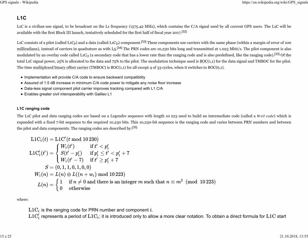
The L1C pilot and data ranging codes are based on a Legendre sequence with length 10 223 used to build an intermediate code (called a Weil code) which is
expanded with a fixed 7-bit sequence to the required 10,230 bits. This 10,230-bit sequence is the ranging code and varies between PRN numbers and between
the pilot and data components. The ranging codes are described by:[35]
where:
is the ranging code for PRN number and component . represents a period of ; it is introduced only to allow a more clear notation. To obtain a direct formula for start
L1C
L1C ranging code
GPS signals - Wikipedia https://en.wikipedia.org/wiki/GPS_signals
15 z 25 21.10.2018, 13:55

from the right side of the formula for and replace all instances of with . is the integer number of L1C chip periods (which is 1⁄1.023 µs) since the origin of GPS time or equivalently, since any GPS
second (starting from 0). is an ordered pair identifying a PRN number and a code (L1CP or L1CD) and is of the form or where is the
PRN number of the satellite, and are symbols (not variables) that indicate the L1CP code or L1CD code, respectively. is an intermediate code: a Legendre sequence whose domain is the set of integers for which .
is an intermediate code called Weil code, with the same domain as . is a 7-bit long sequence defined for 0-based indexes 0 to 6. is the 0-based insertion index of the sequence into the ranging code (specific for PRN number and code ). It is defined in
the Interface Specification (IS) as a 1-based index , therefore .[36]
is the Weil index for PRN number and code designated in the IS.[36]
is the remainder of division (or modulo) operation, which differs to the notation in statements of modular congruence, alsoused in this article.
According to the formula above and the GPS IS, the first bits (equivalently, up to the insertion point of ) of and are the first bits the
corresponding Weil code; the next 7 bits are ; the remaining bits are the remaining bits of the Weil code.
The IS asserts that .[37] For clarity, the formula for does not account for the hypothetical case in which , which would cause
the instance of inserted into to wrap from index 10 229 to 0.
The overlay codes are 1,800 bits long and is transmitted at 100 bit/s, synchronized with the navigation message encoded in L1CD.
For PRN numbers 1 to 63 they are the truncated outputs of maximal period LFSRs which vary in initial conditions and feedback polynomials.[38]
For PRN numbers 64 to 210 they are truncated Gold codes generated by combining 2 LFSR outputs ( and , where is the PRN number) whose initial state
varies. has one of the 4 feedback polynomials used overall (among PRN numbers 64–210). has the same feedback polynomial for all PRN numbers in
the range 64–210.[39]
The L1C navigation data (called CNAV-2) is broadcast in 1,800 bits long (including FEC) frames and is transmitted at 100 bit/s.
The frames of L1C are analogous to the messages of L1C and L5. While L2 CNAV and L5 CNAV use a dedicated message type for ephemeris data, all CNAV-2
frames include that information.
L1C overlay code
CNAV-2 navigation message
GPS signals - Wikipedia https://en.wikipedia.org/wiki/GPS_signals
16 z 25 21.10.2018, 13:55

The common structure of all messages consists of 3 frames, as listed in the adjacent table. The content
of subframe 3 varies according to its page number which is analogous to the type number of L2 CNAV
and L5 CNAV messages. Pages are broadcast in an arbitrary order.[40]
The time of messages (not to be confused with clock correction parameters) is expressed in a different
format than the format of the previous civilian signals. Instead it consists of 3 components:
The week number, with the same meaning as with the other civilian signals. Each messagecontains the week number modulo 8,192 or equivalently, the 13 least significant bits of the weeknumber, allowing direct specification of any date within a cycling 157-year range.
1.
An interval time of week (ITOW): the integer number of 2 hour periods elapsed since the lateststart/end of week. It has range 0 to 83 (inclusive), requiring 7 bits to encode.
2.
A time of interval (TOI): the integer number of 18 second periods elapsed since the period represented by the currentITOW to the beginning of the next message. It has range 0 to 399 (inclusive) and requires 9 bits of data.
3.
TOI is the only content of subframe 1. The week number and ITOW are contained in subframe 2 along with other
information.
Subframe 1 is encoded by a modified BCH code. Specifically, the 8 least significant bits are BCH encoded to generate 51 bits,
then combined using exclusive or with the most significant bit and finally the most significant bit is appended as the most
significant bit of the previous result to obtain the final 52 bits.[41] Subframes 2 and 3 are individually expanded with a 24-bit
CRC, then individually encoded using a low-density parity-check code, and then interleaved as a single unit using a block
interleaver.[42]
Subframes
SubframeBit count
DescriptionRaw Encoded
1 9 52 Time of interval (TOI)
2 576 1,200 Time correction andephemeris data
3 250 548 Variable data
Subframe 3 pages
Page no. Description
1 UTC & IONO
2 GGTO & EOP
3 Reduced almanac
4 Midi almanac
5 Differential correction
6 Text
GPS signals - Wikipedia https://en.wikipedia.org/wiki/GPS_signals
17 z 25 21.10.2018, 13:55

GPS Frequencies
Band Frequency(MHz) Phase Original usage Modernized usage
L1 1575.42(10.23 × 154)
I Encrypted precision P(Y) code
Q Coarse/acquisition (C/A) code C/A, L1 Civilian (L1C), andMilitary (M) code
L2 1227.60(10.23 × 120)
I Encrypted precision P(Y) code
Q unmodulated carrier L2 Civilian (L2C) code andMilitary (M) code
L3 1381.05(10.23 × 135)
used by Nuclear Detonation(NUDET) Detection SystemPayload (NDS):signals nuclear detonations/high-energy infrared events.Used to enforce nuclear testban treaties.
L4 1379.9133...(10.23 × 1214/9) N/A being studied for additional
ionospheric correction[43]:607
L5 1176.45(10.23 × 115)
IN/A
Safety-of-Life (SoL) Data signal
Q Safety-of-Life (SoL) Pilot signal
All satellites broadcast at the same two frequencies, 1.57542 GHz (L1 signal) and 1.2276 GHz (L2 signal). The satellite network uses a CDMA spread-spectrum
technique where the low-bitrate message data is encoded with a high-rate pseudo-random (PRN) sequence that is different for each satellite. The receiver must
be aware of the PRN codes for each satellite to reconstruct the actual message data. The C/A code, for civilian use, transmits data at 1.023 million chips per
second, whereas the P code, for U.S. military use, transmits at 10.23 million chips per second. The L1 carrier is modulated by both the C/A and P codes, while the
L2 carrier is only modulated by the P code.[44] The P code can be encrypted as a so-called P(Y) code which is only available to military equipment with a proper
decryption key. Both the C/A and P(Y) codes impart the precise time-of-day to the user.
Each composite signal (in-phase and quadrature phase) becomes:
where and represent signal powers; and represent codes with/without data . This is a formula for the ideal case (which is not attained in
GPS signals - Wikipedia https://en.wikipedia.org/wiki/GPS_signals
18 z 25 21.10.2018, 13:55

practice) as it does not model timing errors, noise, amplitude mismatch between components or quadrature error (when components are not exactly in
quadrature).
A GPS receiver processes the GPS signals received on its antenna to determine
position, velocity and/or timing. The signal at antenna is amplified, down converted to
baseband or intermediate frequency, filtered (to remove frequencies outside the
intended frequency range for the digital signal that would alias into it) and digitalized;
these steps may be chained in a different order. Note that aliasing is sometimes
intentional (specifically, when undersampling is used) but filtering is still required to
discard frequencies not intended to be present in the digital representation.
For each satellite used by the receiver, the receiver must first acquire the signal and
then track it as long as that satellite is in use; both are performed in the digital
domain in by far most (if not all) receivers.
Acquiring a signal is the process of determining the frequency and code phase (both
relative to receiver time) when it was previously unknown. Code phase must be
determined within an accuracy that depends on the receiver design (especially the
tracking loop); 0.5 times the duration of code chips (approx. 0.489 µs) is a
representative value.
Tracking is the process of continuously adjusting the estimated frequency and phase to match the received signal as close as possible and therefore is a phase
locked loop. Note that acquisition is performed to start using a particular satellite, but tracking is performed as long as that satellite is in use.
In this section, one possible procedure is described for L1 C/A acquisition and tracking, but the process is very similar for the other signals. The described
procedure is based on computing the correlation of the received signal with a locally generated replica of the ranging code and detecting the highest peak or
lowest valley. The offset of the highest peak or lowest valley contains information about the code phase relative to receiver time. The duration of the local replica
is set by receiver design and is typically shorter than the duration of navigation data bits, which is 20 ms.
Acquisition of a given PRN number can be conceptualized as searching for a signal in a bidimensional search space where the dimensions are (1) code phase, (2)
frequency. In addition, a receiver may not know which PRN number to search for, and in that case a third dimension is added to the search space: (3) PRN
Demodulating and Decoding GPS Satellite Signals using theCoarse/Acquisition Gold code.
Acquisition
GPS signals - Wikipedia https://en.wikipedia.org/wiki/GPS_signals
19 z 25 21.10.2018, 13:55

number.
Frequency spaceThe frequency range of the search space is the band where the signal may be located given the receiver knowledge. Thecarrier frequency varies by roughly 5 kHz due to the Doppler effect when the receiver is stationary; if the receiver moves, thevariation is higher. The code frequency deviation is 1/1,540 times the carrier frequency deviation for L1 because the codefrequency is 1/1,540 of the carrier frequency (see § Frequencies used by GPS). The down conversion does not affect thefrequency deviation; it only shifts all the signal frequency components down. Since the frequency is referenced to the receivertime, the uncertainty in the receiver oscillator frequency adds to the frequency range of the search space.
Code phase spaceThe ranging code has a period of 1,023 chips each of which lasts roughly 0.977 µs (see § Coarse/acquisition code). The codegives strong autocorrelation only at offsets less than 1 in magnitude. The extent of the search space in the code phasedimension depends on the granularity of the offsets at which correlation is computed. It is typical to search for the code phasewithin a granularity of 0.5 chips or finer; that means 2,046 offsets. There may be more factors increasing the size of the searchspace of code phase. For example, a receiver may be designed so as to examine 2 consecutive windows of the digitalizedsignal, so that at least one of them does not contain a navigation bit transition (which worsens the correlation peak); thisrequires the signal windows to be at most 10 ms long.
PRN number spaceThe lower PRN numbers range from 1 to 32 and therefore there are 32 PRN numbers to search for when the receiver does nothave information to narrow the search in this dimension. The higher PRN numbers range from 33 to 66. See § Navigationmessage.
If the almanac information has previously been acquired, the receiver picks which satellites to listen for by their PRNs. If the almanac information is not in
memory, the receiver enters a search mode and cycles through the PRN numbers until a lock is obtained on one of the satellites. To obtain a lock, it is necessary
that there be an unobstructed line of sight from the receiver to the satellite. The receiver can then decode the almanac and determine the satellites it should
listen for. As it detects each satellite's signal, it identifies it by its distinct C/A code pattern.
The simplest way to acquire the signal (not necessarily the most effective or least computationally expensive) is to compute the dot product of a window of the
digitalized signal with a set of locally generated replicas. The locally generated replicas vary in carrier frequency and code phase to cover all the already
mentioned search space which is the Cartesian product of the frequency search space and the code phase search space. The carrier is a complex number where
real and imaginary components are both sinusoids as described by Euler's formula. The replica that generates the highest magnitude of dot product is likely the
one that best matches the code phase and frequency of the signal; therefore, if that magnitude is above a threshold, the receiver proceeds to track the signal or
further refine the estimated parameters before tracking. The threshold is used to minimize false positives (apparently detecting a signal when there is in fact no
signal), but some may still occur occasionally.
Simple correlation
GPS signals - Wikipedia https://en.wikipedia.org/wiki/GPS_signals
20 z 25 21.10.2018, 13:55

Using a complex carrier allows the replicas to match the digitalized signal regardless of the signal's carrier phase and to detect that phase (the principle is the
same used by the Fourier transform). The dot product is a complex number; its magnitude represents the level of similarity between the replica and the signal,
as with an ordinary correlation of real-valued time series. The argument of the dot product is an approximation of the corresponding carrier in the digitalized
signal.
As an example, assume that the granularity for the search in code phase is 0.5 chips and in frequency is 500 Hz, then there are 1,023/0.5 = 2,046 codephases and 10,000 Hz/500 Hz = 20 frequencies to try for a total of 20×2,046 = 40,920 local replicas. Note that each frequency bin is centered on its
interval and therefore covers 250 Hz in each direction; for example, the first bin has a carrier at −4.750 Hz and covers the interval −5,000 Hz to −4,500 Hz.
Code phases are equivalent modulo 1,023 because the ranging code is periodic; for example, phase −0.5 is equivalent to phase 1,022.5.
The following table depicts the local replicas that would be compared against the digitalized signal in this example. "•" means a single local replica while "..." is
used for elided local replicas:
Carrier freq.deviation
Code phase (in chips)
0.0 0.5 (more phases) 1,022.0 1,022.5
−4,750 Hz • • ... • •
−4,250 Hz • • ... • •
(morefrequencies) ... ... ... ... ...
4,250 Hz • • ... • •
4,750 Hz • • ... • •
As an improvement over the simple correlation method, it is possible to implement the computation of dot products more efficiently with a Fourier transform.
Instead of performing one dot product for each element in the Cartesian product of code and frequency, a single operation involving FFT and covering all
frequencies is performed for each code phase; each such operation is more computationally expensive, but it may still be faster overall than the previous method
due to the efficiency of FFT algorithms, and it recovers carrier frequency with a higher accuracy, because the frequency bins are much closely spaced in a DFT.
Specifically, for all code phases in the search space, the digitalized signal window is multiplied element by element with a local replica of the code (with no
carrier), then processed with a discrete Fourier transform.
Given the previous example to be processed with this method, assume real-valued data (as opposed to complex data, which would have in-phase and quadrature
components), a sampling rate of 5 MHz, a signal window of 10 ms, and an intermediate frequency of 2.5 MHz. There will be 5 MHz×10 ms = 50,000 samples in
Fourier transform
GPS signals - Wikipedia https://en.wikipedia.org/wiki/GPS_signals
21 z 25 21.10.2018, 13:55

the digital signal, and therefore 25,001 frequency components ranging from 0 Hz to 2.5 MHz in steps of 100 Hz (note that the 0 Hz component is real because it
is the average of a real-valued signal and the 2.5 MHz component is real as well because it is the critical frequency). Only the components (or bins) within 5 kHz
of the central frequency are examined, which is the range from 2.495 MHz to 2.505 MHz, and it is covered by 51 frequency components. There are 2,046code phases as in the previous case, thus in total 51×2,046 = 104,346 complex frequency components will be examined.
Likewise, as an improvement over the simple correlation method, it is possible to perform a single operation covering all code phases for each frequency bin. The
operation performed for each code phase bin involves forward FFT, element-wise multiplication in the frequency domain. inverse FFT, and extra processing so
that overall, it computes circular correlation instead of circular convolution. This yields more accurate code phase determination than the simple correlation
method in contrast with the previous method, which yields more accurate carrier frequency determination than the previous method.
Since the carrier frequency received can vary due to Doppler shift, the points where received PRN sequences begin may not differ from O by an exact integral
number of milliseconds. Because of this, carrier frequency tracking along with PRN code tracking are used to determine when the received satellite's PRN code
begins.[45] Unlike the earlier computation of offset in which trials of all 1,023 offsets could potentially be required, the tracking to maintain lock usually requires
shifting of half a pulse width or less. To perform this tracking, the receiver observes two quantities, phase error and received frequency offset. The correlation of
the received PRN code with respect to the receiver generated PRN code is computed to determine if the bits of the two signals are misaligned. Comparisons of
the received PRN code with receiver generated PRN code shifted half a pulse width early and half a pulse width late are used to estimate adjustment required.[46]
The amount of adjustment required for maximum correlation is used in estimating phase error. Received frequency offset from the frequency generated by the
receiver provides an estimate of phase rate error. The command for the frequency generator and any further PRN code shifting required are computed as a
function of the phase error and the phase rate error in accordance with the control law used. The Doppler velocity is computed as a function of the frequency
offset from the carrier nominal frequency. The Doppler velocity is the velocity component along the line of sight of the receiver relative to the satellite.
As the receiver continues to read successive PRN sequences, it will encounter a sudden change in the phase of the 1,023-bit received PRN signal. This indicates
the beginning of a data bit of the navigation message.[47] This enables the receiver to begin reading the 20 millisecond bits of the navigation message. The TLM
word at the beginning of each subframe of a navigation frame enables the receiver to detect the beginning of a subframe and determine the receiver clock time at
which the navigation subframe begins. The HOW word then enables the receiver to determine which specific subframe is being transmitted.[9][10] There can be a
delay of up to 30 seconds before the first estimate of position because of the need to read the ephemeris data before computing the intersections of sphere
surfaces.
After a subframe has been read and interpreted, the time the next subframe was sent can be calculated through the use of the clock correction data and the
HOW. The receiver knows the receiver clock time of when the beginning of the next subframe was received from detection of the Telemetry Word thereby
enabling computation of the transit time and thus the pseudorange. The receiver is potentially capable of getting a new pseudorange measurement at the
Circular correlation with Fourier transform
Tracking and navigation message decoding
GPS signals - Wikipedia https://en.wikipedia.org/wiki/GPS_signals
22 z 25 21.10.2018, 13:55
beginning of each subframe or every 6 seconds.
Then the orbital position data, or ephemeris, from the navigation message is used to calculate precisely where the satellite was at the start of the message. A
more sensitive receiver will potentially acquire the ephemeris data more quickly than a less sensitive receiver, especially in a noisy environment.[48]
In-phase and quadrature components
GPS Interface Specification
"GPS Interface Specification (GPS-IS-200H)" (http://www.gps.gov/technical/icwg/IS-GPS-200H.pdf) (PDF). 24 September 2013. (describes L1, L2C and P)."GPS Interface Specification (GPS-IS-705D)" (http://www.gps.gov/technical/icwg/IS-GPS-705D.pdf) (PDF). 24 September 2013. (describes L5)."GPS Interface Specification (GPS-IS-800D)" (http://www.gps.gov/technical/icwg/IS-GPS-800D.pdf) (PDF). 24 September 2013. (describes L1C).
"New Civil Signals" (http://www.gps.gov/systems/gps/modernization/civilsignals/).1. "Codeless/Semi-Codeless GPS Access Commitments" (http://www.gps.gov/technical/codeless/).2. GPS-IS-200H, tables 3-Ia, 3-Ib (p. 6–8).3. GPS-IS-200H, § 3.2.1.3, table 3-Ia (p. 4, 7).4. US patent 5576715 (https://worldwide.espacenet.com/textdoc?DB=EPODOC&IDX=US5576715), Litton, James D.; Graham Russell & Richard K. Woo,"Method and apparatus for digital processing in a global positioning system receiver", issued 1996-11-19, assigned to Leica Geosystems
5.
GPS-IS-200H, § 20.3.4.1 (p. 63–130).6. GPS-IS-200H, § 6.4.1 (p. 63–64).7. GPS-IS-200H, § 40.3.3 (p. 207).8. "NAVSTAR GPS User Equipment Introduction" (http://www.navcen.uscg.gov/pubs/gps/gpsuser/gpsuser.pdf) (PDF). US Government. Retrieved 2013-07-24.Section 1.4.2.6.
9.
Bibliography
Notes
GPS signals - Wikipedia https://en.wikipedia.org/wiki/GPS_signals
23 z 25 21.10.2018, 13:55

"Essentials of Satellite Navigation Compendium" (http://www.u-blox.com/images/stories/Resources/gps_compendiumgps-x-02007.pdf) Archived(https://web.archive.org/web/20141107091706/http://www.u-blox.com/images/stories/Resources/gps_compendiumgps-x-02007.pdf) November 7, 2014, atthe Wayback Machine.
10.
GPS-IS-200H, § 6.2.4 (p. 50), § 3.3.4 (p. 41).11. GPS-IS-200H, § 20.3.3.1 (p. 87).12. GPS-IS-200H, § 20.3.3.3.1.1 (p. 90).13. GPS-IS-200H, § 20.3.4.1 (p. 130).14. "Interface Specification IS-GPS-200, Revision D: Navstar GPS Space Segment/Navigation User Interfaces" (https://web.archive.org/web/20120908003700/http://www.losangeles.af.mil/shared/media/document/AFD-070803-059.pdf) (PDF). Navstar GPS Joint Program Office. Archived from the original(http://www.losangeles.af.mil/shared/media/document/AFD-070803-059.pdf) (PDF) on 2012-09-08. Retrieved 2013-07-24. Page 103.
15.
GPS-IS-200H, § 20.3.3.5.1 (p. 108–109).16. GPS-IS-200H, § 40.3.3.5.1 (p. 207–208).17. US Coast Guard GPS FAQ (http://www.navcen.uscg.gov/?pageName=gpsFaq)18. GPS-IS-200H, § 30.3.3 (p. 140).19. Numbered starting from 1. Bit 1 is the first bit in the message and bit 300 is the last one.20. TOW count for the beginning of the next message. It uses the same format than the truncated TOW in LNAV.21. GPS-IS-200H, § 30.3.4.1 (p. 190).22. GPS-IS-200H, § 3.3.3.1.1 (p. 39) Note that synchronization is described in the IS in terms of X1 epochs, which occur each 1.5 seconds and aresynchronized with start/end of GPS week.
23.
GPS-IS-200H, § 3.3.3.1.1 (p. 39).24. "Interface Specification IS-GPS-200 Revision D" (http://www.navcen.uscg.gov/pdf/IS-GPS-200D.pdf) (PDF). United States Coast Guard. 7 December 2004.Retrieved 2010-07-18.
25.
"Satellite Navigation - GPS - Policy - Modernization" (https://www.faa.gov/about/office_org/headquarters_offices/ato/service_units/techops/navservices/gnss/gps/policy/modernization/). FAA.gov. FAA. 13 November 2014. Retrieved 25 September 2018.
26.
GPS-IS-705D, tables 3-Ia, 3-Ib (p. 5 7).27. GPS-IS-705D, § 3.3.2.2 (p. 14).28. GPS-IS-705D, § 20.3.3 (p. 41).29. GPS-IS-705D, § 3.3.3.1.1 (p. 39).30. "IS-GPS-705: NAVSTAR GPS Space Segment / User Segment L5 Interfaces" (http://www.navcen.uscg.gov/pdf/IS-GPS-705.pdf) (PDF). United StatesCoast Guard. 22 September 2005. Retrieved 2010-07-18.
31.
"First GPS III Launch Slips to FY17" (http://www.insidegnss.com/node/4270). Inside GNSS. Retrieved 2015-07-29.32. GPS-IS-800D, § 3.1 (p. 2–3).33. GPS-IS-800D, § 3.2.1.6.1 (p. 4).34.
GPS signals - Wikipedia https://en.wikipedia.org/wiki/GPS_signals
24 z 25 21.10.2018, 13:55

The ranging codes are described in GPS-IS-800D, § 3.2.2.1.1 (p. 7–8) using a different notation.35. GPS-IS-800D, table 3.2-2 (p. 10–12).36. GPS-IS-800D, p. 7.37. GPS-IS-800D, § 3.2.2.1 (p. 6).38. GPS-IS-800D, § 6.3.1.2 (p. 110–111).39. GPS-IS-800D, § 3.5.5.1 (p. 69).40. GPS-IS-800D, § 3.2.3.2 (p. 19–20).41. GPS-IS-800D, § 3.2.3.1 (p. 18).42. Penttinen, Jyrki T. J. The Telecommunications Handbook: Engineering Guidelines for Fixed, Mobile and Satellite Systems (https://books.google.com/books?id=HRQmBgAAQBAJ). John Wiley & Sons. ISBN 9781119944881.
43.
How GPS works. (https://archive.is/20120804185510/http://www.kowoma.de/en/gps/signals.htm) Konowa.de (2005).44. "How a GPS Receiver Gets a Lock" (http://gpsinformation.net/main/gpslock.htm). Gpsinformation.net. Retrieved 2009-10-13.45. "NAVSTAR GPS User Equipment Introduction" (http://www.navcen.uscg.gov/pubs/gps/gpsuser/gpsuser.pdf) (PDF). US Government. Retrieved 2013-07-24.Section 1.4.2.4.
46.
"NAVSTAR GPS User Equipment Introduction" (http://www.navcen.uscg.gov/pubs/gps/gpsuser/gpsuser.pdf) (PDF). US Government. Retrieved 2013-07-24.Section 1.4.2.5.
47.
"AN02 Network Assistance" (http://www.navsync.com/notes2.html). Retrieved 2007-09-10.48.
Retrieved from "https://en.wikipedia.org/w/index.php?title=GPS_signals&oldid=861186885"
This page was last edited on 25 September 2018, at 18:13 (UTC).
Text is available under the Creative Commons Attribution-ShareAlike License; additional terms may apply. By using this site, you agree to the Terms of Use andPrivacy Policy. Wikipedia® is a registered trademark of the Wikimedia Foundation, Inc., a non-profit organization.
GPS signals - Wikipedia https://en.wikipedia.org/wiki/GPS_signals
25 z 25 21.10.2018, 13:55