global radio standards collaboration
TRANSCRIPT

International Technical Characteristics and Test Methods
Part 1; Wireless/Radio Microphones in the 25 MHz to 3 GHz Frequency Range
Draft GRSC 001 Part 1 V 0.0.9 (2004-04)
Global
Radio
Standards
Collaboration

2 Draft GRSC 001 Part 1 V 0.0.9
Reference
Keywords radio, radio mic, testing
Important notice
Copyright Notification

3 Draft GRSC 001 Part 1 V 0.0.9
Contents
Foreword ................................................................................................................................................7
Introduction .............................................................................................................................................7
1. Scope ............................................................................................................................................8
2 References ....................................................................................................................................9
3 Definitions, symbols and abbrevia tions .............................................................................................9 3.1 Definitions............................................................................................................................................................................. 9 3.2 Symbols ............................................................................................................................................................................... 11 3.3 Abbreviations..................................................................................................................................................................... 11
4 Functional characteristics..............................................................................................................12 4.1 Radio microphone descriptions....................................................................................................................................... 12 4.2 In ear monitoring................................................................................................................................................................ 12
5 General........................................................................................................................................12 5.1 Presentation of equipment for testing purposes........................................................................................................... 12 5.1.1 Choice of model for testing........................................................................................................................................ 13 5.1.2 Definitions of alignment and switching ranges ...................................................................................................... 13 5.1.4 Choice of frequencies ................................................................................................................................................. 13 5.1.5 Testing of single channel equipment...................................................................................................................................... 13 5.1.6 Testing of two channel equipment ........................................................................................................................... 13 5.1.7 Testing of multi-channel equipment (more than two channels)........................................................................... 14 5.1.8 Testing of equipment without a permanent external RF port................................................................................ 14 5.1.8.1 Equipment with a permanent internal RF port................................................................................................... 14 5.1.8.2 Equipment with a temporary RF port.................................................................................................................. 14 5.2 Mechanical and electrical design .................................................................................................................................... 14 5.2.1 General........................................................................................................................................................................... 14 5.2.2 Controls ......................................................................................................................................................................... 14 5.2.3 Testing with Integral antenna.................................................................................................................................... 14 5.2.4 Marking (equipment identification).......................................................................................................................... 14 5.3 Interpretation of the measurement results ..................................................................................................................... 15
6 Test conditions, power sources and ambient conditions....................................................................16 6.1 Normal and extreme test-conditions................................................................................................................................ 16 6.2 Test power source ............................................................................................................................................................. 16 6.3 Normal test conditions...................................................................................................................................................... 16 6.3.1 Normal temperature and humidity............................................................................................................................. 16 6.3.2 Normal test power source voltage ............................................................................................................................ 16 6.3.2.1 Mains voltage........................................................................................................................................................ 16 6.3.2.3 Other power sources............................................................................................................................................. 17 6.4 Extreme test conditions..................................................................................................................................................... 17 6.4.1 Extreme temperatures .................................................................................................................................................. 17 6.4.1.1 Procedures for tests at extreme temperatures ................................................................................................... 17 6.4.2 Extreme test power source voltages ......................................................................................................................... 17 6.4.2.1 Mains voltage........................................................................................................................................................ 17 6.4.2.4 Other power sources............................................................................................................................................. 17
7 General conditions ........................................................................................................................18 7.1 Normal test modulation..................................................................................................................................................... 18 7.2 Artificial antenna................................................................................................................................................................ 19 7.3 Test fixture .......................................................................................................................................................................... 19 7.5 Modes of operation of the transmitter............................................................................................................................ 19 7.6 Arrangement for test signals at the input of the transmitter....................................................................................... 20

4 Draft GRSC 001 Part 1 V 0.0.9
8 Methods of measurement and limits for transmitter parameters .......................................................21 8.1 Frequency Stability............................................................................................................................................................ 21 8.1.1 Definition ...................................................................................................................................................................... 21 8.1.2 Method of measurement (analogue)......................................................................................................................... 21 8.1.3 Method of measurement (digital).............................................................................................................................. 21 8.1.3 Limit ............................................................................................................................................................................... 21 8.2 Rated output power........................................................................................................................................................... 21 8.2.1 Definition ...................................................................................................................................................................... 21 8.2.2 Method of measurement for equipment without integral antenna....................................................................... 22 8.2.3 Method of measurement for equipment with integral antenna............................................................................. 22 8.2.3.1 Method of measurement under normal test conditions .................................................................................. 22 8.2.4 Limit ............................................................................................................................................................................... 22 8.3 Necessary bandwidth........................................................................................................................................................ 22 8.3.1 Definition ...................................................................................................................................................................... 22 8.3.2 Measurement of Necessary Bandwidth (BN) (analogue)...................................................................................... 23 8.3.2 Measurement of Necessary Bandwidth (BN) (digital)........................................................................................... 23 8.3.3 Limits ............................................................................................................................................................................. 25 8.4 Spurious emissions............................................................................................................................................................ 26 8.4.1 Definitions .................................................................................................................................................................... 26 8.4.2 Method of measurment............................................................................................................................................... 26 8.4.3 Limits ............................................................................................................................................................................. 27 8.4.4 Measuring receiver...................................................................................................................................................... 28
9 Receiver......................................................................................................................................29 9.1 Spurious emis sions............................................................................................................................................................ 29 9.1.1 Definitions .................................................................................................................................................................... 29 9.1.2 Method of measuring the power level in a specified load..................................................................................... 29 9.1.3 Method of measuring the effective radiated power of the enclosure.................................................................. 29 9.1.4 Method of measuring the radiated power................................................................................................................ 30 9.1.5 Limits ............................................................................................................................................................................. 30
10 Measurement uncertainty..............................................................................................................32
11 Generic EMC Arrangements.........................................................................................................33 11.1 Test conditions .................................................................................................................................................................. 33 11.1.1 General........................................................................................................................................................................... 33 11.1.2 Arrangements for test signals ................................................................................................................................... 33 11.1.2.1 Arrangements for test signals at the input of transmitters ............................................................................. 33 11.1.2.2 Arrangements for test signals at the output of transmitters .......................................................................... 33 11.1.2.3 Arrangements for test signals at the input of receivers .................................................................................. 33 11.1.2.4 Arrangements for test signals at the output of receivers ............................................................................... 34 11.1.2.5 Arrangements for testing transmitter and receiver together (as a system) .................................................. 34 11.1.3 RF exclusion band of radio communications equipment....................................................................................... 34 11.1.4 Narrow band responses of receivers or receivers which are part of transceivers ............................................. 34 11.1.5 Normal test modulation............................................................................................................................................... 35 11.2 Performance assessment................................................................................................................................................... 35 11.2.1 General........................................................................................................................................................................... 35 11.2.2 Equipment which can provide a continuous communication link........................................................................ 36 11.2.3 Equipment which does not provide a continuous communication link.............................................................. 36 11.2.4 Ancillary equipment.................................................................................................................................................... 36 11.2.5 Equipment classification............................................................................................................................................. 36 11.3 Performance criteria ........................................................................................................................................................... 37 11.3.1 Performance criteria for continuous phenomena applied to transmitters and receivers................................... 37 11.3.2 Performance criteria for transient phenomena applied to transmitters and receivers ....................................... 37 11.3.3 Performance criteria for equipment which does not provide a continuous communication link..................... 38 11.3.4 Performance criteria for ancillary equipment tested on a stand alone basis ....................................................... 38 11.4 Applicability overview tables .......................................................................................................................................... 38 11.4.1 EMC emission .............................................................................................................................................................. 39 11.4.2 Immunity ....................................................................................................................................................................... 40 11.5 Methods of measurement and limits for EMC emissions ............................................................................................ 40
5 Draft GRSC 001 Part 1 V 0.0.9
11.5.1 Test configuration....................................................................................................................................................... 40 11.5.2 Enclosure of ancillary equipment measured on a stand alone basis ................................................................... 41 11.5.2.1 Definition................................................................................................................................................................ 41 11.5.2.2 Test method ........................................................................................................................................................... 41 11.5.2.3 Limits ....................................................................................................................................................................... 41 11.5.3 DC power input/output ports .................................................................................................................................... 42 11.5.3.1 Definition................................................................................................................................................................ 42 11.5.3.2 Test method ........................................................................................................................................................... 42 11.5.3.3 Limits ....................................................................................................................................................................... 42 11.5.4 AC mains power input/output ports ......................................................................................................................... 43 11.5.4.1 Definition................................................................................................................................................................ 43 11.5.4.2 Test method ........................................................................................................................................................... 43 11.5.4.3 Limits ....................................................................................................................................................................... 43 11.5.5 Harmonic current emissions (AC mains input port)............................................................................................... 43 11.5.6 voltage fluctuations and flicker (AC mains input port)......................................................................................... 44 11.5.7 Telecommunication ports ........................................................................................................................................... 44 11.5.7.1 Definition................................................................................................................................................................ 44 11.5.7.2 Test method ........................................................................................................................................................... 44 11.5.7.3 Limits ....................................................................................................................................................................... 44 11.6 Test methods and levels for immunity tests .................................................................................................................. 45 11.6.1 Test configuration....................................................................................................................................................... 45 11.6.2 Radio frequency electromagnetic field (80 MHz to 1 000 MHz and 1 400 MHz to 2 000 MHz)........................ 45 11.6.2.1 Definition................................................................................................................................................................ 46 11.6.2.2 Test method ........................................................................................................................................................... 46 11.6.2.3 Performance criteria............................................................................................................................................... 46 11.6.3 Electrostatic discharge................................................................................................................................................ 46 11.6.3.1 Definition................................................................................................................................................................ 46 11.6.3.2 Test method ........................................................................................................................................................... 47 11.6.3.3 Performance criteria ..................................................................................................................................................... 47 11.6.4 Fast transients, common mode.................................................................................................................................. 47 11.6.4.1 Definition................................................................................................................................................................ 47 11.6.4.2 Test method ........................................................................................................................................................... 47 11.6.4.3 Performance criteria............................................................................................................................................... 48 11.6.5 Radio frequency, common mode............................................................................................................................... 48 11.6.5.1 Definition................................................................................................................................................................ 48 11.6.5.2 Test method ........................................................................................................................................................... 48 11.6.5.3 Performance criteria............................................................................................................................................... 49 11.6.6 Transients and surges in the vehicular environment............................................................................................. 49 11.6.6.1 Definition................................................................................................................................................................ 49 11.6.6.2 Test method ........................................................................................................................................................... 49 11.6.6.2.1 Test requirements for 12 V DC powered equipment .................................................................................. 49 11.6.6.2.2 Test requirements for 24 V DC powered equipment .................................................................................. 50 11.6.6.3 Performance criteria............................................................................................................................................... 50 11.6.7 voltage dips and interruptions .................................................................................................................................. 50 11.6.7.1 Definition................................................................................................................................................................ 50 11.6.7.2 Test method ........................................................................................................................................................... 51 11.6.7.3 Performance criteria............................................................................................................................................... 51 11.6.8 Surges............................................................................................................................................................................ 51 11.6.8.1 Definition................................................................................................................................................................ 52 11.6.8.2 Test method ........................................................................................................................................................... 52 11.6.8.3 Performance criteria............................................................................................................................................... 52
12 Specific EMC Arrangements ........................................................................................................53
12.1 Test conditions .............................................................................................................................53 12.1.1 General................................................................................................................................................................................. 53 12.1.2 Arrangements for test signals .......................................................................................................................................... 53 12.1.2.1 Arrangements for test signals at the input of transmitters ................................................................................... 53 12.1.2.2 Arrangements for test signals at the output of transmitters ................................................................................. 54
6 Draft GRSC 001 Part 1 V 0.0.9
12.1.2.3 Arrangements for test signals at the input of receivers ........................................................................................ 54 12.1.2.4 Arrangements for test signals at the output of receivers...................................................................................... 56 12.1.2.5 Arrangements for testing transmitter and receiver together (as a system) ....................................................... 56 12.1.3 Exclusion bands ................................................................................................................................................................. 56 12.1.3.1 Receiver and receivers of transceivers exclusion band......................................................................................... 56 12.1.3.2 Transmitter exclusion band........................................................................................................................................ 56 12.1.4 Narrow band responses of receivers .............................................................................................................................. 57 12.1.5 Normal test modulation..................................................................................................................................................... 57 12.1.5.1 Transmitters.................................................................................................................................................................. 57 12.1.5.2 Receivers....................................................................................................................................................................... 57
12.2 Performance assessment ..............................................................................................................57 12.2.1 General................................................................................................................................................................................. 57 12.2.2 Equipment which can provide a continuous communications link............................................................................ 58 12.2.3 Equipment which does not provide a continuous communications link................................................................... 58 12.2.4 Ancillary equipment .......................................................................................................................................................... 58 12.2.5 Equipment classification................................................................................................................................................... 58
12.3 Performance criteria .....................................................................................................................58 12.3.1 General performance criteria ............................................................................................................................................. 59 12.3.2 Performance criteria for equipment which provides a continuous communication link.......................................... 59 12.3.2.1 Performance criteria for Continuous phenomena applied to Transmitters (CT) and Receivers (CR) ............. 59 12.3.2.2 Performance criteria for Transient phenomena applied to Transmitters (TT) and Receivers (TR) ................. 60 12.3.3 Performance criteria for equipment which does not provide a continuous communication link........................... 60 12.3.4 Performance criteria for ancillary equipment tested on a stand alone basis ............................................................. 61
12.4 Applicability overview...................................................................................................................61 12.4.1 Emission .............................................................................................................................................................................. 61 12.4.1.1 General........................................................................................................................................................................... 61 12.4.1.2 Special conditions ....................................................................................................................................................... 61 12.4.2 Immunity.............................................................................................................................................................................. 61 12.4.2.1 General........................................................................................................................................................................... 61 12.4.2.2 Special conditions ....................................................................................................................................................... 62
Annex A (normative): Measurement of Necessary Bandwidth (BN)............................................... 64
Annex B (normative): Clauses and/or subclauses of the present document relevant for compliance with the essential requirements of EC Council Directives66
Annex C (informative): Examples of wireless microphones, cordless audio, in-ear monitoring and similar RF audio link equipment within the scope of the present document............................................................................................... 67
C.1 Wireless radio microphone equipment ............................................................................................67
C.2 Cordless audio equipment..............................................................................................................67
C.3 RF audio link equipment covered within the scope of the present document......................................68
Annex D (normative): Acoustic stimulation of wireless radio microphones and similar radio communications link equipment, conditions for the test set up and configuration ......................................................................................... 69
D.1 General........................................................................................................................................69
D.2 Audio excitation ...........................................................................................................................69
History..................................................................................................................................................72

7 Draft GRSC 001 Part 1 V 0.0.9
Foreword Global RAdio STandardization RAST was formed in November 1994, to provide an informal multinational information exchange focused on radio standardization trends and developments in the delegates various regions, to facilitate assessing the potential for harmonization and to complement the more formal processes of other bodies, and particularly the ITU in the work of developing international standards recommendations. At the joint RAST - Global Standards Collaboration (GSC), meeting in Sydney in 2001, a new GSC was created combining GRSC (formerly RAST) and the old GSC now GTSC. At the GSC meeting in Ottawa in 2003, radio microphones were listed as a “high interest” area, these documents are produced under produced under a mandate from the 2003 meeting as the start of an international standard, which would be adopted by the worlds standardisation bodies: RESOLUTION GSC-8/5: Radio Microphones
GSC-8
considering
a) from RAST 10/2: Compliance Regimes, Equipment Mobility, Spectrum and Market Implications – A viable objective of RAST 10/2 is to agree on common global specifications for radio microphone products such as those used by the entertainment industries, and to facilitate the free movement and use of radio microphones on a global basis;
b) GRSC members are encouraged to experiment with the elaboration of a single specification for radio microphone products that could be used on a global basis;
c) PSOs were to identify product and product families that would benefit from common global specifications; d) PSOs were to consider the publication of any resulting specifications in an analogous way to that used by the
Partnership Projects;
resolves
a) to work together to identify product families that could benefit from this approach via a nominated rapporteur group; to develop a pilot scheme for radio microphone products having regard for contribution GSC8-070.
The document has been split into two parts, Part 1 covering “Radio Microphones” and Part 2 covering “cordless Audio”.
Introduction An international standard would greatly assist the regulatory authorities in providing common technical standards for radio microphones which, after GSM telephones are the most travelled commercial devices in the world.
In preparing the present document, much attention has been given to assure a low interference probability, while at the same time allowing a maximum flexibility and service to the end-user. It also is intended to make it easier for the frequency management authorities to find harmonised frequency allocations. Common technical specifications and harmonised frequency allocations are expected to reduce greatly the present problems of interference and illegal use. The present document is a testing standard based on spectrum utilisation parameters and does not include performance characteristics that may be required by the user or requirements for interfacing equipment.

8 Draft GRSC 001 Part 1 V 0.0.9
1. Scope The present document covers the minimum characteristics considered necessary in order to make the best use of the available frequencies. It does not necessarily include all the characteristics that may be required by a user, nor does it necessarily represent the optimum performance achievable.
The present document applies to equipment operating on radio frequencies between 25 MHz and 3 GHz, using analogue, digital and hybrid (using both analogue and digital modulation) The present document does not apply to radio microphones or in ear monitoring equipment employing Time Division Multiple Access (TDMA), modulation.
Additional standards or specifications may be required for equipment intended to interface to the Public Switched Telephone Network (PSTN). This facility may be submitted to regulatory conditions.
The present document may be used by accredited test laboratories or manufacturers for testing of the equipment. The performance of the equipment submitted for testing should be representative of the performance of the corresponding production models.
The maximum power recommended for equipment covered by this standard is 50mW mean power National regulations on maximum power output willapply. The types of equipment covered by the present document are as follows:
- professional hand held radio microphones;
- professional body worn radio microphones;
- in ear monitoring systems;
- consumer radio microphones;
- tour guide systems;
- aids for the handicapped (assistive technology).
Note;Test methods within this standard are applicable for equipment with a maximum of 250 mW (mean power)..

9 Draft GRSC 001 Part 1 V 0.0.9
2 References The following documents contain provisions, which, through reference in this text, constitute provisions of the present document.
• References are either specific (identified by date of publication, edition number, Version number, etc.) or non-specific.
• For a specific reference, subsequent revisions do not apply.
• For a non-specific reference, the latest Version applies.
• A non-specific reference to an ETS shall also be taken to refer to later Versions published as an EN with the same number.
[1] ITU-R Recommendation BS.559-2: "Objective measurement of radio-frequency protection ratios in LF, MF and HF broadcasting".
[2] ETR 028; Radio Equipment and Systems (RES);Uncertainties in the measurement of mobile radio equipment characteristics
[3] IEC 60244: "Methods of measurement for radio transmitters".
[4] ITU-R Recommendation BS.468-4: "Measurement of audio-frequency noise voltage level in sound broadcasting".
[5] RCR STD-22 2.0 Specified Radio-Microphone For Land Mobile Radio Station
[6] EN 301 489; Electromagnetic compatibility and Radio spectrum Matters (ERM);ElectroMagnetic Compatibility (EMC) standard for radio equipment and services;Part 1: Common technical requirements
3 Definitions, symbols and abbreviations
3.1 Definitions For the purposes of the present document, the following terms and definitions apply:
antenna port: Port, where a radio frequency antenna is connected to equipment
base station equipment: Radio and/or ancillary equipment intended for operation at a fixed ocation and powered directly or indirectly (e.g. via an AC/DC converter or power supply) by the AC mains network, or an extended local DC mains network.
carrier grid: Evenly spaced raster in a given frequency band for the allocation of carrier frequencies. The minimum distance of two carriers in use is a multiple of the raster dependent on type and usage of the equipment
class of emission: The set of characteristics of an emission, designated by standard symbols, e.g. type of modulation of the main carrier, modulating signal, type of information to be transmitted, and also, if appropriate, any additional signal characteristics.
10 Draft GRSC 001 Part 1 V 0.0.9
conducted measurements: Measurements that are made using a direct connection to the EUT
enclosure port: Physical boundary of the apparatus through which electromagnetic fields may radiate or impinge. In the case of integral antenna equipment, this port is inseparable from the antenna port.
integral antenna: Antenna, with or without a connector, designed as, and declared as by the manufacturer, a an indispensable part of the equipment
integral microphone: Microphone, designed as, and declared as by the manufacturer, an indispensable fixed part of the equipment
limiter threshold: Audio input or output level at which the transmitter audio limiter action may be said to commence. It is specified with any accessible Variable gain controls set according to the manufacturer's instructions, with a sinusoidal input signal of 500 Hz
mean power (of a radio transmitter): The average power supplied to the antenna transmission line by a transmitter during an interval of time sufficiently long compared with the lowest frequency encountered in the modulation taken under normal operating conditions.
mobile equipment: Receiver, transmitter or transmitter/receiver (transceiver) intended for installation and use in a vehicle, and powered by the main battery of the vehicle.
necessary bandwidth: For a given class of emission, the width of the frequency band which is just
sufficient to ensure the transmission of information at the rate and with the quality required under specified conditions.
out-of-band emission: Emission on a frequency or frequencies immediately outside the necessary bandwidth which results from the modulation process, but excluding spurious emissions.
port: Any connection point on or within the Equipment Under Test (EUT) intended for the connection of cables to or from that equipment
portable equipment: Radio and/or ancillary equipment intended for portable (e.g. handheld) operation, powered by its own integral battery.
radiated measurements: Measurements that involve the absolute measurement of a radiated
electromagnetic field
radio frequency (RF) port: Any connection point on or within the EUT intended for the connection of RF cables. RF ports are treated as 50 Ω connection points unless otherwise specified by the manufacturer
radio receiver An item of electronic equipment designed to receive electromagnetic radio frequency emissions.
spurious emissions: Emission on a frequency or frequencies which are outside the necessary bandwidth and the level of which may be reduced without affecting the corresponding transmission of information. Spurious emissions include harmonic emissions, parasitic emissions, intermodulation products and frequency conversion products but exclude out of band emissions.

11 Draft GRSC 001 Part 1 V 0.0.9
3.2 Symbols For the purposes of the present document, the following symbols apply:
λ wavelength in metres µF microFarad µW microWatt
3.3 Abbreviations For the purposes of the present document, the following abbreviations apply:
ac alternating current AR1 Alignment Range 1 AR2 Alignment Range 2 B declared channel Bandwidth (see table 1) BN Necessary Bandwidth dBc dB relative to the carrier level dc direct current E field strength Eo reference field strength erp effective radiated power EUT Equipment Under Test fc carrier frequency fo operating frequency GHz gigaHertz H Henry kHz kiloHertz LF Low Frequency lim limiting MHz megaHertz mW milliWatt nW nanoWatt PSTN Public Switched Telephone Network R distance RBW Resolution BandWidth RF Radio Frequency Ro reference distance TDMA Time Division Multiple Access Tx Transmitter VBW Video BandWidth

12 Draft GRSC 001 Part 1 V 0.0.9
4 Functional characteristics
4.1 Radio microphone descriptions Radio microphones are used to provide a high quality wireless link for use in audio performance for professional use in broadcasting, concerts etc. The radio part of the transmitter and receiver shall be made up exclusively from equipment that has been approved according to the present document.
Other equipment that may be connected to radio microphones shall fulfil the standards applicable to that equipment (if any).
4.2 In ear monitoring In ear monitoring equipment is used by stage and studio performers to receive personal fold back (monitoring) of the performance. This can be just their own Voice or a complex mix of sources. The bandwidth requirement of professional in ear monitoring equipment is similar to those of radio microphones.
The radio part of the transmitter and receiver shall be made up exclusively from equipment that has been approved according to the present document.
Other equipment that may be connected to in ear monitoring equipment shall fulfil the standards applicable to that equipment (if any).
5 General
5.1 Presentation of equipment for testing purposes Each equipment submitted for testing shall fulfil the requirements of the present document on all channels over which it is intended to operate.
The applicant shall complete the appropriate application form when submitting equipment for testing.
For radio microphones that may use a variety of audio capsules the manufacturer shall supply the test sample with an audio test fixture, to substitute the audio capsule, with suitable input and output impedance.
The applicant shall state the channel bandwidth(s) within which the equipment is designed to operate chosen from table 5.1.
Table 5.1: Channel bandwidth
Declared channel Bandwidth (B) Designation 50 kHz L 75 kHz M 100 kHz P 150 kHz Q 200 kHz R
250 kHz S 300 kHz T
Note; Channel Bandwidths need to be defined by manufacturer for digital modulation prior to the next meeting.
The applicant shall state the audio input limiting threshold, (see subclause 5.2.2).
The applicant shall also supply all relevant interface information to allow:
- direct current (dc) power connection;
13 Draft GRSC 001 Part 1 V 0.0.9
- RF connection;
- audio connection;
- the limiting of the transmitter; and
- the setting of any input audio level controls for normal operation, for a sinusoidal input signal of 500 Hz. The manufacturer shall specify the settings of any other controls necessary to avoid invalidating the test measurements.
Besides the technical documentation, the applicant should also supply an operating manual for the device(s).
To simplify and harmonize the testing procedures between the different test Engineers, measurement shall be performed, according to the present document, on samples of equipment defined in subclauses 5.1.1 to 5.1.12.2.
These subclauses are intended to give confidence that the requirements set out in the present document have been met without the necessity of performing measurements on all channels.
5.1.1 Choice of model for testing
The applicant shall provide one or more production model(s) of the equipment, including all antenna(s) designed for the equipment, and that are required to be covered by the testing.
If approval is given on the basis of tests on a preliminary model, the corresponding production models shall be identical in all respects with the preliminary model tested.
In the case of radio microphone equipment without a permanent external RF port, see subclause 5.1.12.
5.1.2 Definitions of alignment and switching ranges
The alignment range is defined as the frequency range over which the receiver and the transmitter can be programmed and/or re-aligned to operate with a single oscillator frequency multiplication, without any physical change of components other than:
- programmable read only memories supplied by the manufacturer or the manufacturer's nominee;
- crystals;
- frequency setting elements (for the receiver and transmitter). These elements shall not be accessible to the end user and shall be declared by the applicant in the application form.
The switching range is the maximum frequency range over which the receiver or the transmitter can be operated without re-programming or realignment.
The applicant shall, when submitting equipment for test, state the alignment ranges for the receiver and transmitter. The applicant shall also state the switching range of the receiver and the transmitter (which may differ).
5.1.4 Choice of frequencies
The frequencies for testing shall be chosen by the applicant.
5.1.5 Testing of single channel equipment
Full tests shall be carried out on a channel closest to the centre frequency of the alignment range on one sample of the equipment.
5.1.6 Testing of two channel equipment
One sample shall be submitted to enable full tests to be carried out on the highest frequency and the lowest frequency of the switching range

14 Draft GRSC 001 Part 1 V 0.0.9
5.1.7 Testing of multi-channel equipment (more than two channels)
One sample of the equipment shall be submitted to enable tests to be carried out on three channels. The closest centre frequency of the switching range of the sample shall correspond to the closest centre frequency of the alignment range.
Full tests shall be carried out on a frequency closest to the centre frequency, and at the lowest and highest frequencies of the switching range.
5.1.8 Testing of equipment without a permanent external RF port
To facilitate relative measurements, use may be made of a test fixture as described in subclause 7.3, or the equipment may be supplied with a permanent internal or temporary internal/external RF port.
5.1.8.1 Equipment with a permanent internal RF port
The way to access a permanent internal RF port shall be stated by the applicant with the aid of a diagram. The fact that use has been made of a permanent internal RF port shall be recorded in the test report.
5.1.8.2 Equipment with a temporary RF port
The applicant shall submit two sets of equipment to the test laboratory, one fitted with a temporary 50 Ω RF connector with the antenna disconnected and the other with the antenna connected. Each equipment shall be used for the appropriate tests.
The way the temporary RF port is implemented shall be stated by the applicant with the aid of a diagram. The fact that use has been made of the temporary RF port to facilitate measurements shall be stated in the test report. The addition of a temporary RF port should not influence the performance of the EUT.
5.2 Mechanical and electrical design
5.2.1 General
The equipment submitted by the applicant shall be designed, constructed and manufactured in accordance with sound engineering practice, and with the aim of minimising harmful interference to other equipment and services.
5.2.2 Controls
Those controls that, if maladjusted, might increase the interfering potentialities of the equipment shall only be accessible by partial or complete disassembly of the device and requiring the use of tools.
5.2.3 Testing with Integral antenna
Testingl of equipment with integral antenna only applies to that equipment together with the antenna originally supplied by the .applicant.
5.2.4 Marking (equipment identification)
The equipment shall be marked in a Visible place. This marking shall be legible, tamper-proof and durable.
The marking shall include:
- the name of the manufacturer or his trade mark;
- ;model number
- serial number;
- operational frequency range;

15 Draft GRSC 001 Part 1 V 0.0.9
5.3 Interpretation of the measurement results The interpretation of the results recorded in the appropriate test report for the measurements described in the present document shall be as follows:
- the measured Value related to the corresponding limit shall be used to decide whether an equipment meets the requirements of the present document;
- the measurement uncertainty Value for the measurement of each parameter shall be separately included in the test report;
- the recorded Value of the measurement uncertainty shall be, for each measurement, equal to or lower than the figures applicable to the test.

16 Draft GRSC 001 Part 1 V 0.0.9
6 Test conditions, power sources and ambient conditions
6.1 Normal and extreme test-conditions Tests shall be made under normal test conditions, and also, where stated, under extreme test conditions.
The test conditions and procedures shall be as specified in subclauses 6.2 to 6.4.2.4.
6.2 Test power source During tests the power source of the equipment shall be replaced by a test power source, capable of producing normal and extreme test voltages as specified in subclauses 6.3.2 and 6.4.2. The internal impedance of the test power source shall be low enough for its effect on the test results to be negligible. For the purpose of the tests, the voltage of the power source shall be measured at the input terminals of the equipment.
For battery operated equipment, the battery shall be removed and the test power source shall be suitably decoupled and applied as close to the equipment battery terminals as practicable. For radiated measurements any external power leads should be arranged so as not to affect the measurements. If necessary the external power supply may be replaced with the equipment's own internal batteries at the required voltage, this shall be stated on the test report.
If the equipment is provided with a power cable or power socket, the test voltage shall be that measured at the point of connection of the power cable to the equipment.
During tests the power source voltages shall be within a tolerance of < ±1 % relative to the voltage at the beginning of each test. The Value of this tolerance can be critical for certain measurements. Using a smaller tolerance provides a better uncertainty Value for these measurements. If internal batteries are used, at the end of each test the voltage shall be within a tolerance of < ±1 % relative to the voltage at the beginning of each test.
6.3 Normal test conditions
6.3.1 Normal temperature and humidity
The normal temperature and humidity conditions for tests shall be any convenient combination of temperature and humidity within the following ranges:
- temperature: +15°C to +35°C;
- relative humidity: 20 % to 75 %.
When it is impracticable to carry out the tests under the conditions stated above, a note to this effect, stating the actual temperature and relative humidity during the tests, shall be added to the test report.
6.3.2 Normal test power source voltage
6.3.2.1 Mains voltage
The normal test voltage for equipment to be connected to the mains shall be the nominal mains voltage. For the purpose of the present document, the nominal voltage shall be the declared mains voltage, or any of the declared mains voltages, for which the equipment was designed.

17 Draft GRSC 001 Part 1 V 0.0.9
6.3.2.3 Other power sources
For operation from other power sources or types of battery (primary or secondary), the normal test voltage shall be that declared by the equipment manufacturer and approved by the test laboratory. The Values shall be stated in the test report.
6.4 Extreme test conditions
6.4.1 Extreme temperatures
For tests at extreme temperatures, measurements shall be made in accordance with the procedures specified in subclause 6.4.1.1, at -10°C and +45°C.
6.4.1.1 Procedures for tests at extreme temperatures
Before measurements are made the equipment shall have reached thermal balance in the test chamber. The equipment shall be switched off during the temperature stabilizing period. If the thermal balance is not checked by measurements, a temperature stabilizing period of at least one hour shall be allowed.
The sequence of measurements shall be chosen and the humidity content in the test chamber shall be controlled so that excessive condensation does not occur.
Before tests at the higher temperatures, the equipment shall be placed in the test chamber and left until thermal balance is attained. The equipment shall then be switched on for one minute in the transmit condition, after which the equipment shall meet the specified requirements.
For tests at the lower extreme temperature the equipment shall be left in the test chamber until thermal balance is attained, then switched to the standby or receive condition for one minute after which the equipment shall meet the specified requirements.
6.4.2 Extreme test power source voltages
6.4.2.1 Mains voltage
The extreme test voltages for equipment to be connected to an ac mains source shall be the nominal mains voltage ±10 %.
6.4.2.4 Other power sources
For equipment using other power sources, or capable of being operated from a Variety of power sources, the extreme test voltages shall be those agreed between the equipment applicant and the testing Engineer and shall be recorded with the results.

18 Draft GRSC 001 Part 1 V 0.0.9
7 General conditions
7.1 Normal test modulation For normal test modulation, the audio frequency shall be a sinusoidal tone of 500 Hz, set at an input level to the transmitter 8 dB below the audio limiting threshold defined in subclauses 5.1 and 5.2.2.
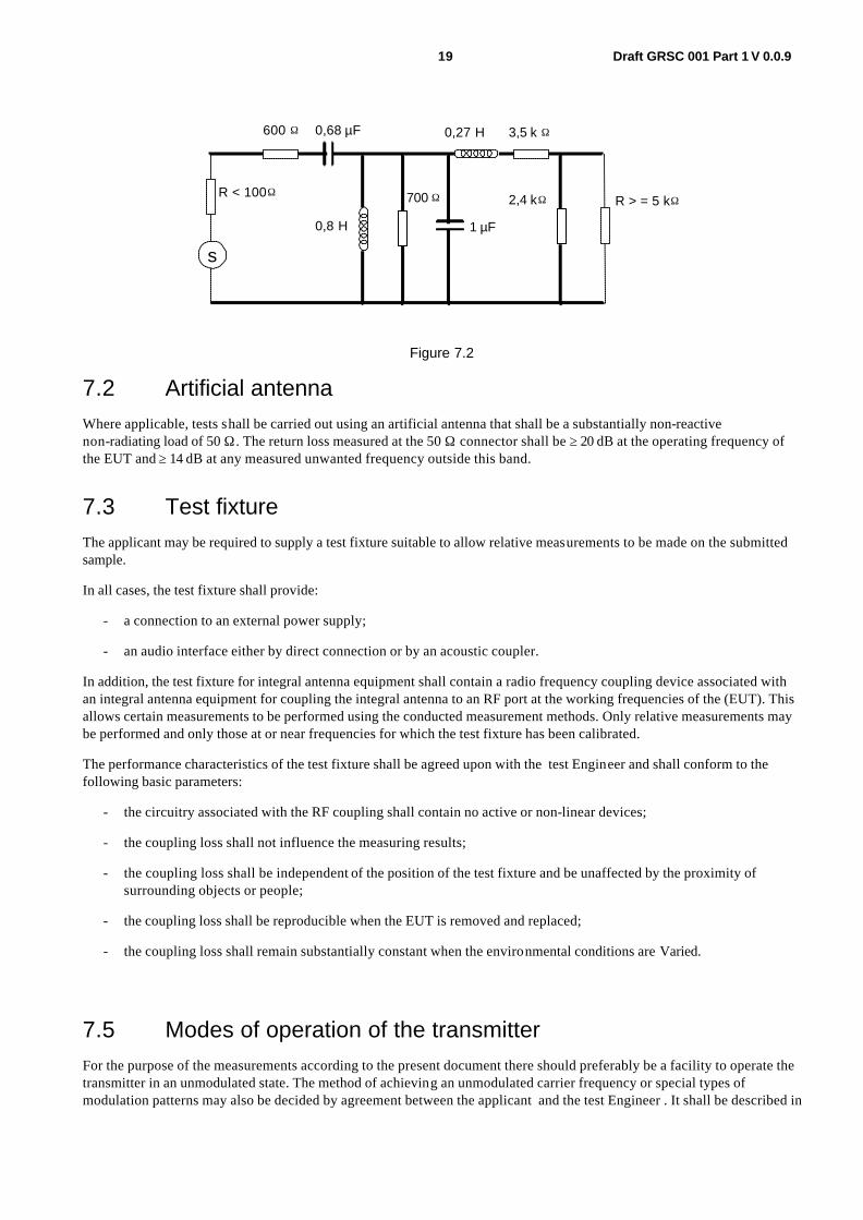
For the purpose of determining the transmitter necessary bandwidth, coloured noise according to ITU-R Recommendation BS.559-2 [1]shall be used, according to the method laid down in subclause 8.3.2. The resulting spectral distribution is shown in figure 7.1. This noise may be generated by a white noise source followed by a passive filter shown in figure 7.2.
Figure 7.1
0
Frequency (Hz)
NOTE 1: Curve A = Frequency spectrum of standardized noise (measured with one-third octave filters). NOTE 2: Curve B = Frequency response characteristics of filter circuit.
19 Draft GRSC 001 Part 1 V 0.0.9
s
R < 100
600 0,68 µF
0,8 H
700
1 µF
2,4 k R > = 5 k
0,27 H 3,5 k Ω
Ω Ω
Ω
Ω Ω
Figure 7.2
7.2 Artificial antenna Where applicable, tests shall be carried out using an artificial antenna that shall be a substantially non-reactive non-radiating load of 50 Ω . The return loss measured at the 50 Ω connector shall be ≥ 20 dB at the operating frequency of the EUT and ≥ 14 dB at any measured unwanted frequency outside this band.
7.3 Test fixture The applicant may be required to supply a test fixture suitable to allow relative measurements to be made on the submitted sample.
In all cases, the test fixture shall provide:
- a connection to an external power supply;
- an audio interface either by direct connection or by an acoustic coupler.
In addition, the test fixture for integral antenna equipment shall contain a radio frequency coupling device associated with an integral antenna equipment for coupling the integral antenna to an RF port at the working frequencies of the (EUT). This allows certain measurements to be performed using the conducted measurement methods. Only relative measurements may be performed and only those at or near frequencies for which the test fixture has been calibrated.
The performance characteristics of the test fixture shall be agreed upon with the test Engineer and shall conform to the following basic parameters:
- the circuitry associated with the RF coupling shall contain no active or non-linear devices;
- the coupling loss shall not influence the measuring results;
- the coupling loss shall be independent of the position of the test fixture and be unaffected by the proximity of surrounding objects or people;
- the coupling loss shall be reproducible when the EUT is removed and replaced;
- the coupling loss shall remain substantially constant when the environmental conditions are Varied.
7.5 Modes of operation of the transmitter For the purpose of the measurements according to the present document there should preferably be a facility to operate the transmitter in an unmodulated state. The method of achieving an unmodulated carrier frequency or special types of modulation patterns may also be decided by agreement between the applicant and the test Engineer . It shall be described in

20 Draft GRSC 001 Part 1 V 0.0.9
the test report. It may involve suitable temporary internal modifications of the EUT. If it is not possible to provide an unmodulated carrier then this has to be stated in the test report.
7.6 Arrangement for test signals at the input of the transmitter For the purpose of the present document, the transmitter audio frequency modulation signal shall be supplied by a generator at the correct impedance applied at the connections of the stated audio input, unless otherwise stated.

21 Draft GRSC 001 Part 1 V 0.0.9
8 Methods of measurement and limits for transmitter parameters
All tests shall be carried out under normal conditions unless otherwise stated. The channel bandwidth declared by the applicant in subclause 5.1 shall be used to determine the limits described in subclauses 8.1.3 and 8.3.
8.1 Frequency Stability
8.1.1 Definition
The spontaneous and/or environmentally caused frequency change within a given time interval
8.1.2 Method of measurement (analogue)
The carrier frequency shall be measured (in the absence of modulation) with the transmitter connected to an artificial antenna (see subclause 7.2). A transmitter without an RF port may be placed in a test fixture (see subclause 7.3) connected to an artificial antenna. The measurement shall be made under normal test conditions (see subclause 6.3), and extreme test conditions (subclauses 6.4.1 and 6.4.2 applied simultaneously).
Radio microphones that also include an RF port for use with other external antennas shall be tested using this port.
8.1.3 Method of measurement (digital)
In the case of transmitters that are incapable of producing an unmodulated carrier, the mean of two frequency measurements taken at the same level on the upper and lower sides of the modulation envelope shall be taken as the measurement.
8.1.3 Limit
The frequency error shall not exceed 20 parts per million.
The measurement uncertainty for this test shall be ±1 x 10 -7.
8.2 Rated output power
8.2.1 Definition
The rated output power is the power that the transmitter shall deliver at its antenna port under the manufacturers specified conditions of operation. For the purposes of this standard this shall be quoted as mean power.

22 Draft GRSC 001 Part 1 V 0.0.9
8.2.2 Method of measurement for equipment without integral antenna
This subclause applies to equipment with a permanent RF port.
The transmitter shall be connected to an artificial antenna (see subclause 7.2) and the power delivered to this artificial antenna shall be measured.
The measurements shall be made under normal test conditions (subclause 6.3) conditions (subclause 6.4) (subclauses 6.4.1 and 6.4.2 applied simultaneously).
8.2.3 Method of measurement for equipment with integral antenna
8.2.3.1 Method of measurement under normal test conditions
On a test site , the sample shall be placed on the support in the following position:
- for equipment with an internal antenna, it shall stand Vertically, with that axis Vertical which is closest to Vertical in normal use;
- for equipment with rigid external antenna, the antenna shall be Vertical;
- for equipment with non-rigid external antenna, with the antenna extended Vertically upwards by a non-conducting support.
The transmitter shall be switched on, with modulation, and the test receiver shall be tuned to the frequency of the signal being measured. The test antenna shall be oriented for Vertical polarization and shall be raised or lowered through the specified height range until a maximum signal level is detected on the test receiver.
The transmitter shall be rotated horizontally through 360° until the highest maximum signal is received.
NOTE: This maximum may be a lower Value than the Value obtainable at heights outside the specified limits.
The transmitter shall be replaced by a substitution antenna and the test antenna raised or lowered as necessary to ensure that the maximum signal is still received. The input signal to the substitution antenna shall be adjusted in level until an equal or a known related level to that detected from the transmitter is obtained in the test receiver.
The carrier power is equal to the power supplied to the substitution antenna, increased by the known relationship if necessary.
The measurement shall be repeated for any alternative antenna supplied by the applicant.
A check should be made in the horizontal plane of polarization to ensure that the Value obtained above is the maximum. If larger Values are obtained, this fact should be recorded in the test report.
8.2.4 Limit
The measured value shall be within +20%, -50% of the manufacturers declared rated output power. Measurement uncertainty = ±0.75 dB for conducted measurements and ±6dB for radiated emissions below 1GHz and ±6dB for measurements above 1GHz.
8.3 Necessary bandwidth
8.3.1 Definition
For a given class of emission, the width of the frequency band which is just sufficient to ensure the transmission of information at the rate and with the quality required under specified conditions.The necessary bandwidth of the transmitter shall be measured under the conditions laid down in subclause 8.3.2.
23 Draft GRSC 001 Part 1 V 0.0.9
8.3.2 Measurement of Necessary Bandwidth (BN) (analogue)
The arrangement of test equipment as shown in annex A shall be used. Note that the noise meter conforms to ITU-R Recommendation BS.468-4 [4] (quasi peak) without weighting filter (flat).
With the Low Frequency (LF) audio signal generator set to 500 Hz, the audio input level to the EUT shall be adjusted to 8 dB below the limiting threshold (-8 dB (lim)) as declared by the manufacturer.
The corresponding audio output level from the demodulator shall be measured and recorded.
NOTE 1: The input impedance of the noise meter should be sufficiently high to avoid more than 0,1 dB change in input level when the meter is switched between input and output.
The audio input level shall be increased by 20 dB, i.e. to +12 dB (lim) and the corresponding change in output level shall be measured.
It shall be checked that the audio output level has increased by ≤ 10 dB.
NOTE 2: If this condition is not met, the initial audio input level should be increased from -8 dB (lim) in 1 dB steps until the above condition is fulfilled, and the input level recorded in the test report. This level shall replace the Value derived from the manufacturer's declaration and is defined as -8 dB (lim).
Measure the input level at the transmitter required to give +12 dB (lim).
The LF generator shall be replaced with the weighted noise source to ITU-R Recommendation BS.559-2 [1], band-limited to 15 kHz as described in IEC 60244 [3] Part 13, and the level shall be adjusted such that the measured input to the transmitter corresponds to +12 dB (lim).
NOTE 3: If the transmitter incorporates any ancillary coding or signalling channels (e.g. pilot-tones), these should be enabled prior to any spectral measurements.
NOTE 4: If the transmitter incorporates more than one audio input, e.g. stereo systems, the second and subsequent channels should be simultaneously driven from the same noise source, attenuated to a level of -6 dB (lim).
The transmitter RF output spectrum shall be measured, using a spectrum analyser with the following settings:
- centre frequency: fc: Transmitter (Tx) nominal frequency;
- dispersion (Span): fc -1 MHz to fc +1 MHz;
- Resolution BandWidth (RBW): 1 kHz;
- Video BandWidth (VBW): 1 kHz;
- detector: Peak hold.
8.3.2 Measurement of Necessary Bandwidth (BN) (digital)
Note: This parameter also includes the limits for spectral components within the out-of-band region.
Principle „Spectrum Mask” measuring method for digital transmitters:
The transmitter shall be modulated with a pseudo random bit sequence (e.g. PRBS23)
Step 1 - Measure the “Carrier Power” with Spectrum Analyzer Setup:
• Center Frequency = FC • Span = Zero span
24 Draft GRSC 001 Part 1 V 0.0.9
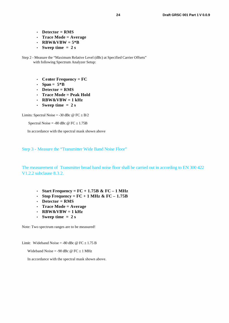
• Detector = RMS • Trace Mode = Average • RBW&VBW = 5*B • Sweep time = 2 s
Step 2 - Measure the “Maximum Relative Level (dBc) at Specified Carrier Offsets” with following Spectrum Analyzer Setup:
• Center Frequency = FC • Span = 5*B • Detector = RMS • Trace Mode = Peak Hold • RBW&VBW = 1 kHz • Sweep time = 2 s
Limits: Spectral Noise = -30 dBc @ FC ± B/2
Spectral Noise = -80 dBc @ FC ± 1.75B
In accordance with the spectral mask shown above
Step 3 - Measure the “Transmitter Wide Band Noise Floor”
The measurement of Transmitter broad band noise floor shall be carried out in according to EN 300 422 V1.2.2 subclause 8.3.2.
• Start Frequency = FC + 1.75B & FC – 1 MHz • Stop Frequency = FC + 1 MHz & FC – 1.75B • Detector = RMS • Trace Mode = Average • RBW&VBW = 1 kHz • Sweep time = 2 s
Note: Two spectrum ranges are to be measured!
Limit: Wideband Noise = -80 dBc @ FC ± 1.75 B
Wideband Noise = -90 dBc @ FC ± 1 MHz
In accordance with the spectral mask shown above.

25 Draft GRSC 001 Part 1 V 0.0.9
Fig 8.1 Method for measuring the relative
suppression of a Digital system
8.3.3 Limits
The transmitter output spectrum shall be within the mask defined in figure 8.2
Power meter /Spectrum Analyser
RF Output
EUTTest Load
Band StopFilter

26 Draft GRSC 001 Part 1 V 0.0.9
Fig 8.2 proposed mask
Measurement uncertainty = ±0.75 dB for conducted measurements and ±6dB for radiated emissions below 1GHz and ±6dB for measurements above 1GHz.
8.4 Spurious emissions
8.4.1 Definitions
Emission on a frequency or frequencies which are outside the necessary bandwidth and the level of which may be reduced without affecting the corresponding transmission of information. Spurious emissions include harmonic emissions, parasitic emissions, intermodulation products and frequency conversion products but exclude out of band emissions.
8.4.2 Method of measurment
On a test site , the sample shall be placed at the specified height on a non-conducting support. The transmitter shall be operated at the power as specified under subclause 8.2, delivered to the antenna (see subclause 5.1.1)..

27 Draft GRSC 001 Part 1 V 0.0.9
Radiation of any spurious components shall be detected by the test antenna and receiver, over the frequency range specified below, excluding 250% (out of band region)band of frequencies centred on the channel on which the transmitter is intended to operate.
NOTE: The 250% (out of band region) exclusion is covered by measurements carried out in subclause 8.3.3.
The measuring receiver shall be tuned over the frequency range 25 MHz to 4 GHz for equipment operating on frequencies below 1 GHz or in the frequency range of 25 MHz to 12,75 GHz for equipment operating on frequencies above 1 GHz.
At each frequency at which a component is detected, the sample shall be rotated to obtain maximum response and the effective radiated power of that component determined by a substitution measurement.
The measurement shall be repeated with the test antenna in the orthogonal polarization plane.
If the transmitter allows for stand-by operation the tests shall be repeated with the transmitter in standby mode.
8.4.3 Limits
Measurement uncertainty = ±0.75 dB for conducted measurements and ±6dB for radiated emissions below 1GHz and ±6dB for measurements above 1GHz.
Spurious emissions shall not exceed the values set out in table 8.1.
TABLE 8.1 Spurious Emission limits for Radio Microphones
Mean power
of the transmitter
Limits
Mean power absolute levels (dBm) or relative levels (dBc) below the mean power supplied to the antenna port in the reference bandwidth
All power ranges
43 + 10 log (P), or 70 dBc, whichever is less stringent
NOTE: Within the band 108 MHz to 137 MHz the limits shall be –50 dBc, without exceeding the absolute mean power of 25 µW (-16 dBm).
Limits on unwanted emissions for radio equipment are considered to be applicable to the range 9 kHz to 300 GHz. However, for practical measurement purposes, the frequency range of spurious emissions may be restricted. For practical purposes, the following measurement parameters in table 8.2 apply.

28 Draft GRSC 001 Part 1 V 0.0.9
Table 8.2
Spurious emission frequency measurement range lower frequency upper frequency
30MHz 1GHz or 3rd Harmonic whichever is higher.
dBc: decibels relative to the unmodulated carrier power of the emission. In the cases which do not have a carrier, for example in some digital modulation schemes where the carrier is not accessible for measurement, the reference level equivalent to dBc is decibels relative to the mean power P.
8.4.4 Measuring receiver
The term measuring receiver refers to either a selective voltmeter or a spectrum analyser. The bandwidth of the measuring receiver is given in table 8.3.
Table 8.3: Reference bandwidth
Frequency being measured Measuring receiver bandwidth 25 MHz to < 30 MHz 9 kHz to 10 kHz
30 MHz to < 1 000 MHz 100 kHz to 120 kHz > 1 000 MHz 1 MHz

29 Draft GRSC 001 Part 1 V 0.0.9
9 Receiver
9.1 Spurious emissions
9.1.1 Definitions
Spurious emissions from the receiver are radio frequency emissions at any frequency, generated by the equipment, antenna, aerial amplifier, down converters or filter.
Manufacturers shall provide a representative sample of the receiver system. The level of spurious emissions shall be measured by either:
a) the power level from an external RF port; and
their effective radiated power when radiated by the cabinet and structure of the equipment (cabinet radiation); or
b) their effective radiated power when radiated by the cabinet and the integral antenna, in the case of hand-portable equipment fitted with such an antenna and no external RF port.
9.1.2 Method of measuring the power level in a specified load
This method applies only to equipment with an external RF port.
The external RF port of the receiver under test shall be connected to a measuring receiver (see subclause 8.4.4). The receiver under test shall be switched on, and the measuring receiver shall be tuned over the frequency range 25 MHz to 4 GHz for equipment operating on frequencies below 1 GHz, or in the frequency range of 25 MHz to 12,75 GHz for equipment operating on frequencies above 1 GHz.
At each frequency at which a spurious component is detected, the power level shall be recorded as the spurious level delivered into the specified load.
9.1.3 Method of measuring the effective radiated power of the enclosure
This method applies only to equipment with an external RF port.
On a test site, the equipment shall be placed at the specified height on a non-conducting support and in the position closest to normal use as declared by the manufacturer. The receiver antenna connector shall be connected to an artificial antenna (see subclause 7.2).
The test antenna shall be oriented for Vertical polarization and the length of the test antenna shall be chosen to correspond to the instantaneous frequency of the measuring receiver (see subclause 8.4.4). The output of the test antenna shall be connected to a measuring receiver. The receiver shall be switched on and the measuring receiver shall be tuned over the frequency range as specified in subclause 9.1.2. At each frequency at which a spurious component is detected, the test antenna shall be raised and lowered through the specified range of height until a maximum signal level is detected by the measuring receiver. When a test site is used there is no need to Vary the height of the antenna. The receiver shall then be rotated through 360° in the horizontal plane until the maximum signal level is detected by the measuring receiver. The maximum signal level detected by the measuring receiver shall be noted.
The receiver shall be replaced by a substitution antenna .
The substitution antenna shall be oriented for Vertical polarization and the length of the substitution antenna shall be adjusted to correspond to the frequency of the spurious component detected.
The substitution antenna shall be connected to a calibrated signal generator.
The frequency of the calibrated signal generator shall be set to the frequency of the spurious component detected.

30 Draft GRSC 001 Part 1 V 0.0.9
The input attenuator setting of the measuring receiver shall be adjusted in order to increase the sensitivity of the measuring receiver, if necessary.
The test antenna shall be raised and lowered through the specified range of height to ensure that the maximum signal is received. The input signal to the substitution antenna shall be adjusted to the level that produces a level detected by the measuring receiver, that is equal to the level noted while the spurious component was measured, corrected for the change of input attenuator setting of the measuring receiver. The input level to the substitution antenna shall be recorded as power level, corrected for the change of input attenuator setting of the measuring receiver.
The measurement shall be repeated with the test antenna and the substitution antenna oriented for horizontal polarization.
The measure of the effective radiated power of the spurious components is the larger of the two power levels recorded for each spurious component at the input to the substitution antenna, corrected for the gain of the antenna if necessary.
9.1.4 Method of measuring the radiated power
This method applies only to equipment with an integral antenna.
The method of measurement shall be performed according to subclause 9.1.3, except that the receiver input shall be connected to the integral antenna and not to an artificial antenna.
9.1.5 Limits
Shall be in accordance with table 9.1.

31 Draft GRSC 001 Part 1 V 0.0.9
Table 9.1
Receivers and idle/standby transmitters
- 57 dBm 9 kHz ≤ f ≤ 1 GHz
- 47 dBm 1 GHz < f
Measurement uncertainty = ±6dB.

32 Draft GRSC 001 Part 1 V 0.0.9
10 Measurement uncertainty The accumulated measurement uncertainties of the test system in use for the parameters to be measured shall not exceed those given in table 10.1. This is in order to ensure that the measurements remain within an acceptable standard. Uncertainty Values for the RF parameters are Valid to 1 GHz unless otherwise stated.
Table 10.1: Measurement uncertainty
Parameter Uncertainty RF frequency < ±1 x 10⁻⁷ Audio Output power < ±0,5 dB Radiated RF power < ±6 dB Conducted RF power Variations using a test fixture < ±0,75 dB Maximum frequency deviation: - within 300 Hz and 6 kHz of audio frequency < ±5 % - within 6 kHz and 25 kHz of audio frequency < ±3 dB Deviation limitation < ±5 % Radiated emission of transmitter, Valid up to 12,75 GHz < ±6 dB Radiated emission of receiver, Valid up to 12,75 GHz < ±6 dB
For the test methods, according to the present document, the uncertainty figures are Valid to a confidence level of 95 % calculated according to the methods described in ETR 028 [2].

33 Draft GRSC 001 Part 1 V 0.0.9
11 Generic EMC Arrangements
11.1 Test conditions
11.1.1 General
The equipment shall be tested under normal test conditions according to this standard, which are within the manufacturers declared range of humidity, temperature and supply voltage. The test conditions shall be recorded in the test report.
The test configuration and mode of operation shall represent the intended use and shall be recorded in the test report.
For emission and immunity tests, specific product related information on the test modulation, test conditions and tests arrangements, etc., are found in clause 12 dealing with this particular type of radio equipment.
11.1.2 Arrangements for test signals
Adequate measures shall be taken to avoid the effect of immunity test signals on both the measuring equipment and the signal sources for the wanted signals located outside the test environment.
11.1.2.1 Arrangements for test signals at the input of transmitters
The signal source providing the transmitter under test with the modulation signal for the normal test modulation shall be located outside the test environment, unless the transmitter is modulated by its own internal source, see clause 12.
The transmitter shall be modulated with normal test modulation, by an internal or external signal source capable of delivering the normal test modulation as specified in clause 12.
11.1.2.2 Arrangements for test signals at the output of transmitters
The measuring equipment for the wanted RF output signal from the transmitter under test shall be located outside the test environment.
For transmitters with an integral antenna, the wanted RF output signal to establish a communication link shall be delivered from the EUT to an antenna located within the test environment. This antenna shall be connected to the external measuring equipment by a coaxial cable.
For transmitters with a removable antenna, the wanted RF output signal to establish a communication link shall be delivered from the antenna connector to the external measuring equipment by a shielded transmission line, such as a coaxial cable. Adequate measures shall be taken to minimize the effect of unwanted common mode currents on the external conductor of the transmission line at the point of entry to the transmitter.
Unless otherwise specified in clause 12 for the particular type of radio equipment, the level of the wanted RF output signal in transmit mode of operation shall be set to the maximum rated RF power for the EUT, modulated with the normal test modulation.
11.1.2.3 Arrangements for test signals at the input of receivers
The signal source providing the receiver under test with the wanted RF input signal shall be located outside the test environment.
The signal source shall be modulated with normal test modulation as specified in clause 12 for the particular type of radio equipment.
For receivers with an integral antenna, the wanted RF input signal to establish a communication link shall be presented to the EUT from an antenna located within the test environment. This antenna shall be connected to the external RF signal source by a coaxial cable.
34 Draft GRSC 001 Part 1 V 0.0.9
For receivers with a removable antenna, the wanted RF input signal to establish a communication link shall be presented to the antenna connector of the EUT by a shielded transmission line, such as a coaxial cable. The transmission line shall be connected to the external RF signal source. Adequate measures shall be taken to minimize the effect of unwanted common mode currents on the external conductor of the shielded transmission line at the point of entry to the receiver.
Unless otherwise specified in clause 12 relevant for this type of radio equipment, the level of the wanted RF input signal shall be set to be approximately 40 dB above the minimum level necessary to achieve a receiver performance which meets the relevant specified performance criteria, measured while the power amplifiers generating the EM disturbance are switched on, but without excitation. This increased level of the wanted RF input signal is expected to represent a normal operation signal level and should be sufficient to avoid the broadband noise from the power amplifiers generating the EM disturbance from influencing the measurement.
11.1.2.4 Arrangements for test signals at the output of receivers
The measuring equipment for the output signal from the receiver under test shall be located outside the test environment.
For receivers with an analogue speech output the audio output from the acoustic transducer should be coupled via an electrically non-conductive acoustic tube to an external audio distortion meter or other appropriate measuring equipment outside of the test environment. Where it is not practical to use an electrically non-conductive acoustic tube, then other means of connecting the receiver output signal to the external audio distortion meter or other measuring equipment shall be provided and recorded in the test report.
For receivers with a non-speech output the output signal shall be coupled via an electrically non-conductive means to the external measuring equipment outside the test environment. If the receiver has an output connector or port providing the wanted output signal, then this port shall be used via a cable, consistent with the standard cable used in normal operation, connected to the external measuring equipment outside the test environment. The measuring equipment may be supplied by the manufacturer.
Precautions shall be taken to ensure that any effect on the test due to the coupling means is minimized.
11.1.2.5 Arrangements for testing transmitter and receiver together (as a system)
Transmitters and receivers may be tested for immunity as a system when combined as a transceiver or the combined equipment is of a size which allows simultaneous testing. In this case the transceiver or transmitter and receiver shall be located inside the test environment and shall be exposed simultaneously to the immunity test signals.
For transceivers or transmitters and receivers operating at the same frequency, the wanted output signal of the transmitter may be used via a suitable attenuator and applied to the input of the receiver as the wanted input signal.
For transceivers or transmitters and receivers operating at different frequencies in duplex mode the arrangements are defined in clause 12 relevant for the particular type of radio equipment.
11.1.3 RF exclusion band of radio communications equipment
The RF exclusion band applies to radio equipment with an operating frequency up to 2 GHz, or for equipment operating above 2 GHz, but whose RF bandwidth extends to a frequency below 2 GHz.
For equipment operating at frequencies above 2 GHz and whose RF bandwidth does not extend to a frequency below 2 GHz, there is no exclusion band.
This exclusion band is always product dependent and defined in clause 12 dealing with this particular type of radio equipment.
11.1.4 Narrow band responses of receivers or receivers which are part of transceivers
Responses on receivers or the receiver part of (duplex) transceivers occurring during the immunity tests at discrete frequencies which are narrow band responses (spurious responses), are identified by the following method:
35 Draft GRSC 001 Part 1 V 0.0.9
If during the test the immunity RF test signal (see subclauses 11.6.2 and 11.6..5) causes non-compliance of the receiver with the specified performance criteria (see subclause 11.3), it is necessary to establish whether this non-compliance is due to a narrow band response or a wideband phenomenon. Therefore, the frequency of the test signal is increased by an amount equal to twice the nominal 6 dB bandwidth of the IF filter immediately preceding the demodulator of the receiver, or if appropriate, the bandwidth over which the apparatus is intended to operate, as declared by the manufacturer. The test is repeated with the frequency of the test signal decreased by the same amount.
If the receiver is then in either or both frequency offset cases in compliance with the specified performance criteria, the response is considered as a narrow band response.
If the receiver still does not comply with the specified performance criteria, this may be due to the fact that the offset has made the frequency of the unwanted signal correspond to the frequency of another narrow band response. Under these circumstances the procedure is repeated with an increase and decrease of the frequency of the test signal adjusted two and a half times the bandwidth referred to above.
If the receiver still does not comply with the specified performance criteria in either or both frequency offset cases, the phenomena is considered wide band and therefore an EMC problem and the equipment fails the test.
For immunity tests, narrow band responses shall be disregarded.
Particular performance criteria typical for this type of EUT and information about any product type dependent nominal frequency offset to be used for the identification of narrowband responses can be found in clause 12 dealing with this particular type of radio equipment.
Where no narrow band responses of receivers are permitted, this shall be stated within clause 12 dealing with this particular type of radio equipment.
11.1.5 Normal test modulation
For the purpose of EMC tests, the transmitter under test shall be modulated according to the normal test modulation specified in clause 12 dealing with the particular type of radio equipment.
For the purpose of EMC tests, the receiver under test shall be provided with a wanted RF input signal modulated according to the normal test mo dulation specified in clause 12 dealing with the particular type of radio equipment.
11.2 Performance assessment
11.2.1 General
The manufacturer shall at the time of submission of the equipment for test, supply the following information to be recorded in the test report:
- the primary functions of the radio equipment to be assessed during and after the EMC exposure;
- the intended functions of the radio equipment which shall be in accordance with the documentation accompanying the equipment;
- the user control functions and stored data that are required for normal operation and the method to be used to assess whether these have been lost after the EMC exposure;
- the type of modulation, the characteristics of the transmission used for testing (random bit stream, message format, etc.) and the necessary test equipment delivered to enable the assessment of the EUT;
- the ancillary equipment to be combined with the radio equipment for testing (where applicable);
- an exhaustive list of ports, with the maximum cable lengths allowed, classified as either power or telecommunication/signal/control. Power ports shall further be classified as AC or DC power;
- the bandwidth of the IF filter immediately preceding the demodulator;

36 Draft GRSC 001 Part 1 V 0.0.9
- the method to be used to verify that a communication link is established and maintained (if appropriate);
- the operating frequency bands over which the equipment is intended to operate;
- any equipment thermal limitation which prevent continuous testing of the EUT;
- the environment(s) in which the equipment is intended to be used.
If additional product related information is required, these can be found in clause 12.
11.2.2 Equipment which can provide a continuous communication link
For radio equipment of non-specialized nature or for radio equipment tested in combination with ancillary equipment, the normal test modulation, test arrangements, etc., shall apply.
11.2.3 Equipment which does not provide a continuous communication link
For radio equipment which does not provide a continuous communication link and/or ancillary equipment intended to be tested on a stand-alone basis, the manufacturer shall specify the permissible minimum level of performance or degradation of performance during and/or after the EMC exposure.
The manufacturer shall furthermore define the test method(s) for the assessment of the actual level of performance or degradation of performance during and/or after the EMC exposure. Under these circumstances the manufacturer shall additionally provide the following information also for inclusion in the test report:
- the primary functions of the EUT during and after EMC stress;
- the intended functions of the EUT which shall be in accordance with the documentation accompanying the equipment;
- suitable pass/fail criteria for the EUT;
- the method of monitoring the actual level of performance and/or the actual degradation of performance of the EUT.
The assessment of the actual performance or its degradation which is carried out during and/or after the EMC exposure, shall be simp le, but at the same time give adequate proof that the primary functions of the equipment are operational.
11.2.4 Ancillary equipment
At the manufacturer's discretion ancillary equipment may be tested and assessed:
• applying the provisions of the present document:
- separately to the ancillary equipment; or
- to the combination of ancillary and radio equipment;
• applying another appropriate EMC standard.
In each case, compliance enables the ancillary equipment to be used with different receivers, transmitters or transceivers.
11.2.5 Equipment classification
For the purpose of the EMC performance assessment in the present document, the radio equipment and/or associated ancillary equipment under test shall be classified into one of the following three classes:
- equipment for fixed use (e.g. base station equipment); or
- equipment for vehicular use (e.g. mobile equipment); or
- equipment for portable use (portable equipment)

37 Draft GRSC 001 Part 1 V 0.0.9
taking into account the definitions in subclause 3.1.
This classification determines the extent of applicable EMC tests. However, the following instructions shall also apply to multiple use radio and/or ancillary equipment:
- radio and/or ancillary equipment for portable use or combinations thereof declared as capable of being powered for intended use by the main battery of a vehicle shall additionally be considered as equipment for vehicular use;
- radio and/or ancillary equipment for portable or vehicular use or combinations thereof declared as capable of being powered for intended use by an AC mains or DC network shall additionally be considered as equipment for fixed use.
Subsequently, for multiple use radio and/or ancillary equipment more than one set of equipment test requirements listed in tables 11.2 and 11.3 has to be taken into account.
Additionally radio equipment when integrated within a host equipment shall meet the requirements of the present document.
11.3 Performance criteria The performance criteria are used to take a decision on whether a radio equipment passes or fails immunity tests.
For the purpose of the present document four categories of performance criteria apply:
- performance criteria for continuous phenomena applied to transmitters;
- performance criteria for transient phenomena applied to transmitters;
- performance criteria for continuous phenomena applied to receivers;
- performance criteria for transient phenomena applied to receivers.
Normally, the performance criteria depend on the type of radio equipment. Thus, this clause only contains general performance criteria commonly used for the assessment of radio equipment. More specific and product-related performance criteria for a dedicated type of radio equipment may be found in clause 12 dealing with this particular type of radio equipment.
11.3.1 Performance criteria for continuous phenomena applied to transmitters and receivers
If no further details are given in clause 12 dealing with this particular type of radio equipment, the following general performance criteria for continuous phenomena shall apply.
During and after the test, the apparatus shall continue to operate as intended. No degradation of performance or loss of function is allowed below a permissible performance level specified by the manufacturer when the apparatus is used as intended. In some cases this permissible performance level may be replaced by a permissible loss of performance.
During the test the EUT shall not unintentionally transmit or change its actual operating state and stored data.
If the minimum performance level or the permissible performance loss is not specified by the manufacturer, then either of these may be deduced from the product description and documentation and what the user may reasonably expect from the apparatus if used as intended.
11.3.2 Performance criteria for transient phenomena applied to transmitters and receivers
If no further details are given in clause 12 dealing with this particular type of radio equipment, the following general performance criteria for transient phenomena shall apply.
After the test, the apparatus shall continue to operate as intended. No degradation of performance or loss of function is allowed below a permissible performance level specified by the manufacturer, when the apparatus is used as intended. In some cases this permissible performance level may be replaced by a permissible loss of performance.

38 Draft GRSC 001 Part 1 V 0.0.9
During the EMC exposure to an electromagnetic phenomenon, a degradation of performance is, however, allowed. No change of the actual mode of operation (e.g. unintended transmission) or stored data is allowed.
If the minimum performance level or the permissible performance loss is not specified by the manufacturer, then either of these may be deduced from the product description and documentation and what the user may reasonably expect from the apparatus if used as intended.
11.3.3 Performance criteria for equipment which does not provide a continuous communication link
For radio equipment which does not provide a continuous communication link, the performance criteria described in the subclauses above are not appropriate, then the manufacturer shall declare, for inclusion in the test report, his own specification for an acceptable level of performance or degradation of performance during and/or after the immunity tests. The performance specification shall be included in the product description and documentation. The related specifications set out in subclause 11.2.3 have also to be taken into account.
The performance criteria specified by the manufacturer shall give the same degree of immunity protection as called for in the foregoing subclauses.
11.3.4 Performance criteria for ancillary equipment tested on a stand alone basis
If ancillary equipment is intended to be tested on a stand alone basis, the performance criteria described in the subclauses above are not appropriate, then the manufacturer shall declare, for inclusion in the test report, his own specification for an acceptable level of performance or degradation of performance during and/or after the immunity tests. The performance specification shall be included in the product description and documentation. The related specifications set out in subclause 11.2.3 have also to be taken into account.
The performance criteria specified by the manufacturer shall give the same degree of immunity protection as called for in the foregoing subclauses.
11.4 Applicability overview tables The applicability overview tables below give a comprehensive overview about all EMC tests specified in the present document for radio and/or associated ancillary equipment.
The applicability of EMC tests specified in the this clause depends on the actual type of radio and/or associated ancillary equipment under test. All tests are port-related EMC tests. For a certain type of EUT not having a particular type of port or for operational/technical reasons, the related EMC tests may not apply. In these cases, subclause 12.4 of clause 12 dealing with this particular type of radio equipment provides specifications or restrictions to the applicability of EMC tests for the actual type of EUT. In the case that the present document is used in a stand-alone basis it is required that both the decision and the justification not to apply any particular test to any particular port be recorded in the test report.
Signal and control ports intended for connection to lines which may carry DC power shall be assessed only as signal and control ports.

39 Draft GRSC 001 Part 1 V 0.0.9
11.4.1 EMC emission
Table 11.2: EMC emission measurements for radio and associated ancillary equipment specified in the present document, overview
Phenomenon Application Equipment test requirement Reference Radio and
ancillary equipment for
fixed use (e.g. base station
equipment)
Radio and ancillary equipment for vehicular use (e.g. mobile equipment)
Radio and ancillary equipment for portable use
(portable equipment)
clause in the present
document
radiated emission
enclosure of ancillary
equipment
applicable for stand alone
testing
applicable for stand alone testing
applicable for stand alone testing
11.5.2
conducted emission
DC power input/output port
applicable Applicable not applicable 11.5.3
conducted emission
AC mains input/output port
applicable not applicable not applicable 11.5.4
harmonic current
emissions
AC mains input port
applicable not applicable not applicable 11.5.5
voltage fluctuations and
flicker
AC mains input port
applicable not applicable not applicable 11.5.6
conducted emission
telecommunication port
applicable not applicable not applicable 11.5.7
40 Draft GRSC 001 Part 1 V 0.0.9
11.4.2 Immunity
Table 11.3: Immunity tests for radio and associated ancillary equipment specified in the present document, overview
Phenomenon Application Equipment test requirement Reference Radio and
ancillary equipment for
fixed use (e.g. base station
equipment)
Radio and ancillary equipment for vehicular use (e.g. mobile equipment)
Radio and ancillary equipment for portable use
(portable equipment)
subclause in the present
document
RF electromagnetic
field (80 MHz to 2 000 MHz)
enclosure applicable applicable applicable 11.6.2
electrostatic discharge
enclosure applicable applicable applicable 11.6.3
fast transients common mode
signal, telecommunicatio
n and control ports, DC and AC
power ports
applicable not applicable not applicable 11.6.4
RF common mode 0,15 MHz
to 80 MHz
signal, telecommunicatio
n and control ports, DC and AC
power ports
applicable applicable not applicable 11.6.5
transients and surges
DC power input ports
not applicable applicable not applicable 11.6.6
voltage dips and interruptions
AC mains power input ports
applicable not applicable not applicable 11.6.7
surges, line to line and line to
ground
AC mains power input ports,
telecommunication ports
applicable not applicable not applicable 11.6.8
11.5 Methods of measurement and limits for EMC emissions
11.5.1 Test configuration
This subclause defines the requirements for test configurations:
- measurements shall be made in the operational mode producing the largest emission in the frequency band being investigated consistent with normal applications;
- the equipment shall be configured in a manner which is representative for normal/typical operation, where practical;
- where radio equipment is provided with an integral antenna, it shall be tested with the antenna fitted in a manner typical of normal intended use, unless declared as a removable antenna;
- if the equipment is part of a system, or can be connected to ancillary equipment, then it shall be acceptable to test the equipment while connected to the minimum representative configuration of ancillary equipment necessary to exercise the ports;
- if the equipment has a large number of ports, then a sufficient number shall be selected to simulate actual operational conditions and to ensure that all the different types of termination are covered;
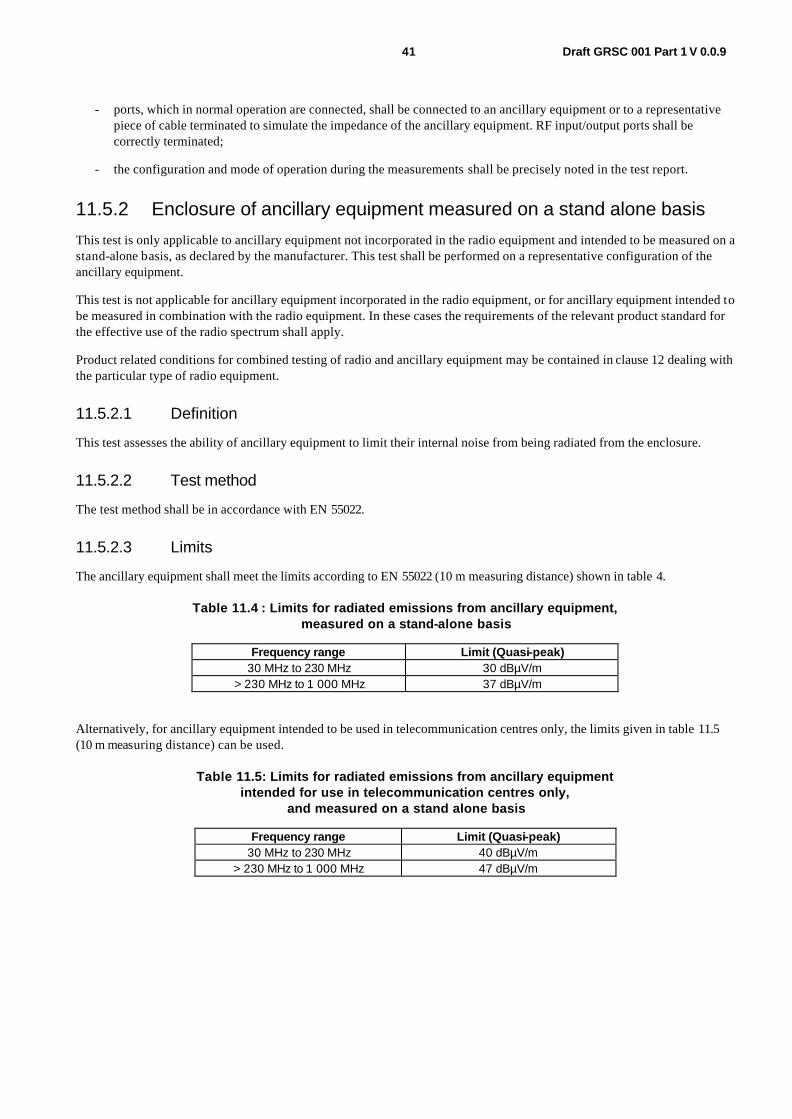
41 Draft GRSC 001 Part 1 V 0.0.9
- ports, which in normal operation are connected, shall be connected to an ancillary equipment or to a representative piece of cable terminated to simulate the impedance of the ancillary equipment. RF input/output ports shall be correctly terminated;
- the configuration and mode of operation during the measurements shall be precisely noted in the test report.
11.5.2 Enclosure of ancillary equipment measured on a stand alone basis
This test is only applicable to ancillary equipment not incorporated in the radio equipment and intended to be measured on a stand-alone basis, as declared by the manufacturer. This test shall be performed on a representative configuration of the ancillary equipment.
This test is not applicable for ancillary equipment incorporated in the radio equipment, or for ancillary equipment intended to be measured in combination with the radio equipment. In these cases the requirements of the relevant product standard for the effective use of the radio spectrum shall apply.
Product related conditions for combined testing of radio and ancillary equipment may be contained in clause 12 dealing with the particular type of radio equipment.
11.5.2.1 Definition
This test assesses the ability of ancillary equipment to limit their internal noise from being radiated from the enclosure.
11.5.2.2 Test method
The test method shall be in accordance with EN 55022.
11.5.2.3 Limits
The ancillary equipment shall meet the limits according to EN 55022 (10 m measuring distance) shown in table 4.
Table 11.4 : Limits for radiated emissions from ancillary equipment, measured on a stand-alone basis
Frequency range Limit (Quasi-peak) 30 MHz to 230 MHz 30 dBµV/m
> 230 MHz to 1 000 MHz 37 dBµV/m
Alternatively, for ancillary equipment intended to be used in telecommunication centres only, the limits given in table 11.5 (10 m measuring distance) can be used.
Table 11.5: Limits for radiated emissions from ancillary equipment intended for use in telecommunication centres only,
and measured on a stand alone basis
Frequency range Limit (Quasi-peak) 30 MHz to 230 MHz 40 dBµV/m
> 230 MHz to 1 000 MHz 47 dBµV/m

42 Draft GRSC 001 Part 1 V 0.0.9
11.5.3 DC power input/output ports
This test is applicable for radio equipment and ancillary equipment for fixed use that may have DC cables longer than 3 m (see subclause 11.2.1 - manufacturer's declaration).
If the DC power cable of the radio and/or the ancillary equipment is less than or equal to 3 m in length, and intended for direct connection to a dedicated AC/DC power supply, then the measurement shall be performed on the AC power input port of that power supply as specified in subclause 11.5.4. If the DC power cable is longer than 3 m, then the measurement shall additionally be performed on the DC power port of the radio and/or ancillary equipment.
This test shall be performed on a representative configuration of the radio equipment, the associated ancillary equipment, or a representative configuration of the combination of radio and ancillary equipment.
11.5.3.1 Definition
This test assesses the ability of the EUT to limit its internal noise from being present on the DC power input/output ports.
11.5.3.2 Test method
The test method shall be in accordance with EN 55022 and the Artificial Mains Networks (AMN) shall be connected to a DC power source.
The measurement frequency range extends from 150 kHz to 30 MHz. When the EUT is a transmitter operating at frequencies below 30 MHz, then the exclusion band for transmitters applies (see subclause 11.1.3) for measurements in the transmit mode of operation.
For emission measurements on DC output ports the relevant port shall be connected via an AMN to a load drawing the rated current of the source.
11.5.3.3 Limits
The equipment shall meet the limits below including the average limit and the quasi-peak limit when using, respectively, an average detector receiver and a quasi-peak detector receiver and measured in accordance with the method described in subclause 11.5.3.2. If the average limit is met when using a quasi-peak detector, the equipment shall be deemed to meet both limits and measurement with the average detector is unnecessary.
The equipment shall meet the limits according to EN 55022 , shown in table 11.6.
Table11. 6: Limits for conducted emissions
Frequency range Limit (Quasi-peak) Limit (Average) 0,15 MHz to 0,5 MHz 66 dBµV - 56 dBµV 56 dBµV - 46 dBµV > 0,5 MHz to 5 MHz 56 dBµV 46 dBµV > 5 MHz to 30 MHz 60 dBµV 50 dBµV
NOTE: The limit decreases linearly with the logarithm of the frequency in the range 0,15 MHz to 0,50 MHz.
Alternatively, for equipment intended to be used in telecommunication centres only, the limits given in table 11.7 may be used.
Table 11.7: Limits for conducted emissions of equipment intended to be used in telecommunication centres only
Frequency range Limit (Quasi-peak) Limit (Average) 0,15 MHz to 0,5 MHz 79 dBµV 66 dBµV > 0,5 MHz to 30 MHz 73 dBµV 60 dBµV
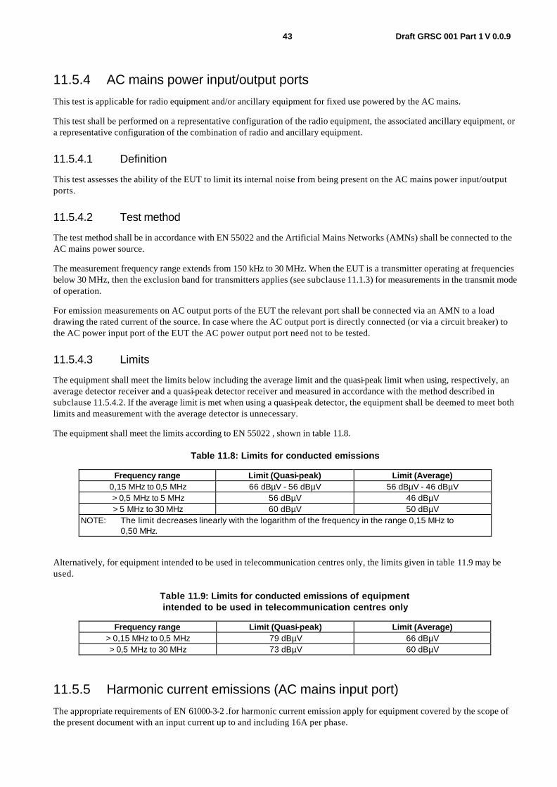
43 Draft GRSC 001 Part 1 V 0.0.9
11.5.4 AC mains power input/output ports
This test is applicable for radio equipment and/or ancillary equipment for fixed use powered by the AC mains.
This test shall be performed on a representative configuration of the radio equipment, the associated ancillary equipment, or a representative configuration of the combination of radio and ancillary equipment.
11.5.4.1 Definition
This test assesses the ability of the EUT to limit its internal noise from being present on the AC mains power input/output ports.
11.5.4.2 Test method
The test method shall be in accordance with EN 55022 and the Artificial Mains Networks (AMNs) shall be connected to the AC mains power source.
The measurement frequency range extends from 150 kHz to 30 MHz. When the EUT is a transmitter operating at frequencies below 30 MHz, then the exclusion band for transmitters applies (see subclause 11.1.3) for measurements in the transmit mode of operation.
For emission measurements on AC output ports of the EUT the relevant port shall be connected via an AMN to a load drawing the rated current of the source. In case where the AC output port is directly connected (or via a circuit breaker) to the AC power input port of the EUT the AC power output port need not to be tested.
11.5.4.3 Limits
The equipment shall meet the limits below including the average limit and the quasi-peak limit when using, respectively, an average detector receiver and a quasi-peak detector receiver and measured in accordance with the method described in subclause 11.5.4.2. If the average limit is met when using a quasi-peak detector, the equipment shall be deemed to meet both limits and measurement with the average detector is unnecessary.
The equipment shall meet the limits according to EN 55022 , shown in table 11.8.
Table 11.8: Limits for conducted emissions
Frequency range Limit (Quasi-peak) Limit (Average) 0,15 MHz to 0,5 MHz 66 dBµV - 56 dBµV 56 dBµV - 46 dBµV > 0,5 MHz to 5 MHz 56 dBµV 46 dBµV > 5 MHz to 30 MHz 60 dBµV 50 dBµV
NOTE: The limit decreases linearly with the logarithm of the frequency in the range 0,15 MHz to 0,50 MHz.
Alternatively, for equipment intended to be used in telecommunication centres only, the limits given in table 11.9 may be used.
Table 11.9: Limits for conducted emissions of equipment intended to be used in telecommunication centres only
Frequency range Limit (Quasi-peak) Limit (Average) > 0,15 MHz to 0,5 MHz 79 dBµV 66 dBµV > 0,5 MHz to 30 MHz 73 dBµV 60 dBµV
11.5.5 Harmonic current emissions (AC mains input port)
The appropriate requirements of EN 61000-3-2 .for harmonic current emission apply for equipment covered by the scope of the present document with an input current up to and including 16A per phase.

44 Draft GRSC 001 Part 1 V 0.0.9
11.5.6 voltage fluctuations and flicker (AC mains input port)
The appropriate requirements of EN 61000-3-3 for voltage fluctuations and flicker apply for equipment covered by the scope of the present document with an input current up to and including 16A per phase.
11.5.7 Telecommunication ports
This test is applicable for radio equipment and/or ancillary equipment for fixed use which have telecommunication ports.
This test shall be performed on a representative configuration of the radio equipment, the associated ancillary equipment, or a representative configuration of the combination of radio and ancillary equipment.
11.5.7.1 Definition
This test assesses the EUT unwanted emission present at the telecommunication ports.
11.5.7.2 Test method
The test method shall be in accordance with EN 55022.
The measurement frequency range extends from 150 kHz to 30 MHz. When the EUT is a transmitter operating at frequencies below 30 MHz, then the exclusion band for transmitters applies (see subclause 11.1.3) for measurements in the transmit mode of operation.
11.5.7.3 Limits
The telecommunication ports shall meet the limits according to EN 55022 shown in table 11.10.
Table 11.10: Limits for conducted emissions from telecommunication ports
Frequency range voltage limits dB (µV)
Current limits dB (µA)
MHz Quasi-peak Average Quasi-peak Average 0,15 to 0,5 84 to 74 74 to 64 40 to 30 30 to 20 0,5 to 30 74 64 30 20
NOTE 1: The limits decrease linearly with the logarithm of the frequency in the range 0,15 MHz to 0,5 MHz. NOTE 2: The current and voltage disturbance limits are derived for use with an impedance stabilization
network (ISN) which presents a common mode (asymmetric mode) impedance of 150 O to the telecommunication port under test (conversion factor is 20 log10 150/I = 44 dB).
NOTE 3: The emission requirement only applies to telecommunication ports as specified in EN 55022. The provisional relaxation of 10 dB will be reviewed no later than 3 years after the date of withdrawal based on the results and interference cases seen in this period. Wherever possible it is recommended to comply with the limits without the provisional relaxation.
Alternatively, for equipment intended to be used in telecommunication centres only, the limits given in table 11.11 may be used.

45 Draft GRSC 001 Part 1 V 0.0.9
Table 11.11: Limits for conducted emissions from telecommunication ports of equipment intended for use in telecommunication centres only
Frequency range voltage limits dB (µV)
Current limits dB (µA)
MHz Quasi-peak Average Quasi-peak Average 0,15 to 0,5 97 to 87 84 to 74 53 to 43 40 to 30 0,5 to 30 87 74 43 30
NOTE 1: The limits decrease linearly with the logarithm of the frequency in the range 0,15 MHz to 0,5 MHz. NOTE 2: The current and voltage disturbance limits are derived for use with an Impedance Stabilization
Network (ISN), which presents a common mode (asymmetric mode) impedance of 150 O to the telecommunication port under test (conversion factor is 20 log10 150/I = 44 dB).
11.6 Test methods and levels for immunity tests
11.6.1 Test configuration
This subclause defines the requirements for test configurations:
- the tests shall be made in the mode(s) of operation specified in subclause 12.1 in clause 12 dealing with this particular type of radio equipment;
- the tests shall be carried out at a point within the specified normal operating environmental range and at the rated supply voltage for the equipment;
- if the equipment is part of a system, or can be connected to ancillary equipment, then it shall be acceptable to test the equipment connected to the minimum representative configuration of ancillary equipment necessary to exercise the ports;
- where radio equipment is provided with an integral antenna, it shall be tested with the antenna fitted in a manner typical of normal intended use, unless declared as a removable antenna;
- for the immunity tests of ancillary equipment, without a separate pass/fail criteria, the receiver or transmitter coupled to the ancillary equipment, shall be used to judge whether the ancillary equipment passes or fails;
- if the equipment has a large number of ports, then a sufficient number shall be selected to simulate actual operational conditions and to ensure that all the different types of termination are covered;
- ports, which in normal operation are connected, shall be connected to an ancillary equipment or to a representative piece of cable terminated to simulate the impedance of the ancillary equipment. RF input/output ports shall be correctly terminated;
- ports which are not connected to cables during normal intended operation, e.g. service connectors, programming connectors, temporary connectors etc. shall not be connected to any cables for the purpose of EMC testing. Where cables have to be connected to these ports, or interconnecting cables have to be extended in length in order to exercise the Equipment Under Test (EUT), precautions shall be taken to ensure that the evaluation of the EUT is not affected by the addition or extension of these cables;
- the configuration and mode of operation during the tests shall be precisely noted in the test report.
11.6.2 Radio frequency electromagnetic field (80 MHz to 1 000 MHz and 1 400 MHz to 2 000 MHz)
This test is applicable for radio equipment and associated ancillary equipment.
This test shall be performed on a representative configuration of the radio equipment, the associated ancillary equipment, or a representative configuration of the combination of radio and ancillary equipment.
46 Draft GRSC 001 Part 1 V 0.0.9
11.6.2.1 Definition
This test assesses the ability of the EUT to operate as intended in the presence of a radio frequency electromagnetic field disturbance.
11.6.2.2 Test method
The test method shall be in accordance with EN 61000-4-3.
The following requirements and evaluation of test results shall apply:
- the test level shall be 3 V/m (measured unmodulated). The test signal shall be amplitude modulated to a depth of 80 % by a sinusoidal audio signal of 1 000 Hz. If the wanted signal is modulated at 1 000 Hz, then an audio signal of 400 Hz shall be used;
- the test shall be performed over the frequency range 80 MHz to 1 000 MHz and 1 400 MHz to 2 000 MHz with the exception of the exclusion band for transmitters, receivers and duplex transceivers (see clause 11.1.3), as appropriate;
- for receivers and transmitters the stepped frequency increments shall be 1 % frequency increment of the momentary used frequency, unless specified otherwise in Clause 12 dealing with the relevant type of radio equipment;
- further product related spot frequency tests may be specified in Clause 12dealing with the particular type of radio equipment;
- responses on receivers occurring at discrete frequencies, which are narrow band responses, shall be disregarded from the test (see subclause 11.1);
- the frequencies selected and used during the test shall be recorded in the test report.
11.6.2.3 Performance criteria
For transmitters the performance criteria for continuous phenomena for transmitters shall apply (see subclause 12.3 of clause 12 dealing with this particular type of radio equipment).
For receivers the performance criteria for continuous phenomena for receivers shall apply (see subclause 12.3 of clause 12 dealing with this particular type of radio equipment).
For ancillary equipment the pass/failure criteria supplied by the manufacturer (see subclause 11.3.4) shall apply, unless the ancillary equipment is tested in connection with a receiver or transmitter in which case the corresponding performance criteria above shall apply.
11.6.3 Electrostatic discharge
This test is applicable for radio equipment and associated ancillary equipment.
This test shall be performed on a representative configuration of the radio equipment, the associated ancillary equipment, or a representative configuration of the combination of radio and ancillary equipment.
11.6.3.1 Definition
This test assesses the ability of the EUT to operate as intended in the event of an electrostatic discharge.

47 Draft GRSC 001 Part 1 V 0.0.9
11.6.3.2 Test method
The test method shall be in accordance with EN 61000-4-2 .
For radio equipment and ancillary equipment the following requirements and evaluation of test results shall apply.
The test severity level for contact discharge shall be 4 kV and for air discharge 8 kV. All other details, including intermediate test levels, are contained within EN 61000-4-2 .
Electrostatic discharges shall be applied to all exposed surfaces of the EUT except where the user documentation specifically indicates a requirement for appropriate protective measures (see EN 61000-4-2 ).
11.6.3.3 Performance criteria
For transmitters the performance criteria for transient phenomena for transmitter shall apply (see subclause 12.3 of Clause 12 dealing with the particular type of radio equipment).
For receivers the performance criteria for transient phenomena for receivers shall apply (see subclause 12.3 of Clause 12 dealing with the particular type of radio equipment).
For ancillary equipment the pass/failure criteria supplied by the manufacturer (see subclause 11.3.4) shall apply, unless the ancillary equipment is tested in connection with a receiver or transmitter in which case the corresponding performance criteria above shall apply.
11.6.4 Fast transients, common mode
This test shall be performed on the AC mains power port (if any) of radio equipment and associated ancillary equipment.
This test shall be additionally performed on signal ports, telecommunication ports, control ports, and DC power ports, of radio equipment and associated ancillary equipment, if the cables may be longer than 3 m.
Where this test is not carried out on any port because the manufacturer declares that it is not intended to be used with cables longer than 3 m, a list of ports, which were not tested for this reason, shall be included in the test report.
This test shall be performed on a representative configuration of the radio equipment or a representative configuration of the combination of radio and ancillary equipment.
11.6.4.1 Definition
This test assesses the ability of the EUT to operate as intended in the event of fast transients present on one of the input/output ports.
11.6.4.2 Test method
The test method shall be in accordance with EN 61000-4-4 .
The following requirements and evaluation of test results shall apply:
- the test level for signal ports, telecommunication ports, and control ports shall be 0,5 kV open circuit voltage as given in EN 61000-4-4;
- the test level for DC power input ports shall be 0,5 kV open circuit voltage as given EN 61000-4-4 ;
- the test level for AC mains power input ports shall be 1 kV open circuit voltage as given EN 61000-4-4 .

48 Draft GRSC 001 Part 1 V 0.0.9
11.6.4.3 Performance criteria
For transmitters the performance criteria for transient phenomena for transmitter shall apply (see subclause 12.3 of clause 12 dealing with this particular type of the radio equipment).
For receivers the performance criteria for transient phenomena for receivers shall apply (see subclause 12.3 of Clause 12 dealing with this particular type of the radio equipment).
For ancillary equipment the pass/failure criteria supplied by the manufacturer (see subclause 11.3.4) shall apply, unless the ancillary equipment is tested in connection with a receiver or transmitter in which case the corresponding performance criteria shall apply.
11.6.5 Radio frequency, common mode
This test shall be performed on the AC mains power port (if any) of radio equipment and associated ancillary equipment.
This test shall be additionally performed on signal ports, telecommunication ports, control ports, and DC power ports, of radio equipment and associated ancillary equipment, if the cables may be longer than 3 m.
Where this test is not carried out on any port because the manufacturer declares that it is not intended to be used with cables longer than 3 m, a list of ports, which were not tested for this reason, shall be included in the test report.
This test shall be performed on a representative configuration of the radio equipment, the associated ancillary equipment, or a representative configuration of the combination of radio and ancillary equipment.
11.6.5.1 Definition
This test assesses the ability of the EUT to operate as intended in the presence of a radio frequency electromagnetic disturbance on the input/output ports.
11.6.5.2 Test method
The test method shall be in accordance with EN 61000-4-6.
The following requirements and evaluation of test results shall apply:
- the test level shall be severity level 2 as given in EN 61000-4-6 corresponding to 3 V rms unmodulated. The test signal shall then be amplitude modulated to a depth of 80 % by a sinusoidal audio signal of 1 000 Hz. If the wanted signal is modulated at 1 000 Hz, then the test signal of 400 Hz shall be used;
- the test shall be performed over the frequency range 150 kHz to 80 MHz with the exception of an exclusion band for transmitters, and for receivers and duplex transceivers, (see subclause 11.1);
- for receivers and transmitters the stepped frequency increments shall be 1 % frequency increment of the momentary frequency in the frequency range 150 kHz to 80 MHz, unless specified otherwise in clause 12 dealing with the particular type of radio equipment;
- the injection method to be used shall be selected according to the basic standard EN 61000-4-6;
- responses on receivers or receiver parts of transceivers occurring at discrete frequencies which are narrow band responses (spurious responses), are disregarded from the test, (see subclause 11.1);
- the frequencies of the immunity test signal selected and used during the test shall be recorded in the test report.

49 Draft GRSC 001 Part 1 V 0.0.9
11.6.5.3 Performance criteria
For transmitters the performance criteria for continuous phenomena for transmitter shall apply (see subclause 12.3 of clause 12 dealing with the particular type of the radio equipment).
For receivers the performance criteria for continuous phenomena for receivers shall apply (see subclause 12.3 of clause 12 dealing with the particular type of the radio equipment).
For ancillary equipment the pass/failure criteria supplied by the manufacturer (see subclause 11.3.4) shall apply, unless the ancillary equipment is tested in connection with receivers or transmitters in which case the corresponding performance criteria above shall apply.
11.6.6 Transients and surges in the vehicular environment
These tests are applicable to radio and ancillary equipment intended for vehicular use (i.e. for mobile equipment).
These tests shall be performed on nominal 12 V and 24 V DC supply voltage input ports of mobile radio and ancillary equipment, which are also intended for mobile use in vehicles.
These tests shall be performed on a representative configuration of the mobile radio equipment, the associated ancillary equipment, or a representative configuration of the combination of radio and ancillary equipment.
11.6.6.1 Definition
These tests assess the ability of the EUT to operate as intended in the event of transients and surges present on their DC power input ports in a vehicular environment.
11.6.6.2 Test method
The test method shall be in accordance with ISO 7637-1 for 12 V DC powered equipment and ISO 7637-2 for 24 V DC powered equipment.
11.6.6.2.1 Test requirements for 12 V DC powered equipment
Where the manufacturer in his installation documentation requires the radio equipment to have a direct connection to the 12 V main vehicle battery the requirements in a) shall apply.
Where the manufacturer does not require the radio equipment to have a direct connection to the 12 V main vehicle battery the requirements in a) and b) shall apply:
a) Pulse 3a and 3b, level II, with the test time reduced to 5 min for each;
Pulse 4, level II, 5 pulses, with the characteristics as follows:
Vs = -5 V; Va = -2,5 V; t6 = 25 ms; t7 = 50 ms; t8 = 5 s; tf = 5 ms; pulse cycle time: 60 s
b) Pulse 1, level II: t1 = 2,5 s; 10 pulses;
Pulse 2, level II: t1 = 2,5 s; 10 pulses;
Pulse 7, level II: 5 pulses.
Where the manufacturer declares that the radio equipment requires a direct connection to the main vehicle battery, and therefore the tests in accordance with the requirements b) are not carried out, this shall be stated in the test report.
50 Draft GRSC 001 Part 1 V 0.0.9
11.6.6.2.2 Test requirements for 24 V DC powered equipment
Where the manufacturer in his installation documentation requires the radio equipment to have a direct connection to the 24 V main vehicle battery the requirements in c) shall apply.
Where the manufacturer does not require the radio equipment to have a direct connection to the 24 V main vehicle battery the requirements in c) and d) shall apply:
c) Pulse 3a and 3b, level II, with the test time reduced to 5 min for each;
Pulse 4, level II, 5 pulses, with the characteristics as follows:
Vs = -10 V; Va = -5 V; t6 = 25 ms; t7 = 50 ms; t8 = 5 s; tf = 10 ms; pulse cycle time: 60 s;
d) Pulse 1a, level II: t1 = 2,5 s; Ri = 25 O; 10 pulses;
Pulse 1b, level II: t1 = 2,5 s; Ri = 100 O; 10 pulses;
Pulse 2, level II: t1 = 2,5 s; 10 pulses.
Where the manufacturer declares that the radio equipment requires a direct connection to the main vehicle battery, and therefore the tests in accordance with the requirements d) are not carried out, this shall be stated in the test report.
Radio and ancillary equipment designed to operate at both DC power voltages shall be tested in both configurations.
11.6.6.3 Performance criteria
For transmitters pulse 3a and 3b the performance criteria for continuous phenomena for transmitters shall apply (see subclause 12.3).
For pulse 1, 1a, 1b, 2, 4 and 7 the performance criteria for transient phenomena for transmitter shall apply (see subclause 12.3 of clause 12 dealing with this particular type of the radio equipment), with the exception that a communication link need not to be maintained during the EMC exposure and may have to be re-established.
For receivers pulse 3a and 3b the performance criteria for continuous phenomena for receivers shall apply (see subclause 12.3 of clause 12 dealing with this particular type of the radio equipment).
For pulse 1, 1a, 1b, 2, 4 and 7 the performance criteria for transient phenomena for receivers shall apply (see subclause 12.3 of clause 12 dealing with this particular type of the radio equipment), with the exception that a communication link need not to be maintained during the EMC exposure and may have to be re-established.
For ancillary equipment the pass/failure criteria supplied by the manufacturer (see subclause 11.3.4) shall apply, unless the ancillary equipment is tested in connection with the radio equipment in which case the corresponding performance criteria above shall apply.
11.6.7 voltage dips and interruptions
This test shall be performed on the AC mains power port (if any) of radio equipment and associated ancillary equipment.
These tests shall be performed on a representative configuration of the radio equipment, the associated ancillary equipment, or a representative configuration of the combination of radio and ancillary equipment.
11.6.7.1 Definition
These tests assess the ability of the EUT to operate as intended in the event of voltage dips and interruptions present on the AC mains power input ports.
51 Draft GRSC 001 Part 1 V 0.0.9
11.6.7.2 Test method
The following requirements and evaluation of test results shall apply.
The test method shall be in accordance with EN 61000-4-11.
The test levels shall be:
- a voltage dip corresponding to a reduction of the supply voltage of 30 % for 10 ms; and
- a voltage dip corresponding to a reduction of the supply voltage of 60 % for 100 ms; and
- a voltage interruption corresponding to a reduction of the supply voltage of greater than 95 % for 5 000 ms.
11.6.7.3 Performance criteria
For a voltage dip corresponding to a reduction of the supply voltage of 30 % for 10 ms the following performance criteria apply:
- for transmitters the performance criteria for transient phenomena for transmitter shall apply (see subclause 12.3 of clause 12 dealing with this particular type of the radio equipment);
- for receivers the performance criteria for transient phenomena for receiver shall apply (see subclause 12.3 of clause 12 dealing with the particular type of the radio equipment).;
- for ancillary equipment the pass/failure criteria supplied by the manufacturer (see subclause 12.3.4) shall apply, unless the ancillary equipment is tested in connection with a receiver or transmitter in which case the corresponding performance criteria above shall apply.
For a voltage dip corresponding to a reduction of the supply voltage of 60 % for 100 ms and/or a voltage interruption corresponding to a reduction of the supply voltage of greater than 95 % for 5 000 ms the following performance criteria apply:
- in the case where the equipment is fitted with or connected to a battery back-up, the performance criteria for transient phenomena for transmitters or for receivers shall apply (see subclause 12.3 of clause 12 dealing with this particular type of the radio equipment);
- in the case where the equipment is powered solely from the AC mains supply (without the use of a parallel battery back-up) volatile user data may have been lost and if applicable the communication link need not to be maintained and lost functions should be recoverable by user or operator;
- no unintentional responses shall occur at the end of the test;
- in the event of loss of function(s) or in the event of loss of user stored data, this fact shall be recorded in the test report;
- for ancillary equipment the pass/failure criteria supplied by the manufacturer (see subclause 12.3.4) shall apply, unless the ancillary equipment is tested in connection with a receiver or transmitter in which case the corresponding performance criteria above shall apply.
11.6.8 Surges
This test shall be performed on the AC mains power input port (if any) of radio equipment and associated ancillary equipment.
This test shall be additionally performed on telecommunication ports, if any.
These tests shall be performed on a representative configuration of the radio equipment, the associated ancillary equipment, or a representative configuration of the combination of radio and ancillary equipment.
52 Draft GRSC 001 Part 1 V 0.0.9
11.6.8.1 Definition
These tests assess the ability of the EUT to operate as intended in the event of surges present on the AC mains power input ports and telecommunication ports.
11.6.8.2 Test method
The test method shall be in accordance with EN 61000-4-5.
The following requirements and evaluation of test results shall apply:
- the test level for telecommunication ports, intended to be directly connected to a telecommunication network, shall be 0,5 kV line to ground as given in EN 61000-4-5. In this case the total output impedance of the surge generator shall be in accordance with the basic standard EN 61000-4-5;
- the test level for AC mains power input ports shall be 1 kV line to ground and 0,5 kV line to line with the output impedance of the surge generator as given in the EN 61000-4-5;
- the test generator shall provide the 1,2/50 µs pulse as defined in EN 61000-4-5.
11.6.8.3 Performance criteria
For transmitters the performance criteria for transient phenomena for transmitters shall apply (see subclause 12.3 of clause 12 dealing with this particular type of the radio equipment).
For receivers the performance criteria for transient phenomena for receivers shall apply (see subclause 12.3 of clause 12 dealing with this particular type of the radio equipment).
For ancillary equipment the pass/failure criteria supplied by the manufacturer (see subclause 12.3.4) shall apply, unless the ancillary equipment is tested in connection with a receiver or transmitter in which case the corresponding performance criteria above shall apply.
53 Draft GRSC 001 Part 1 V 0.0.9
12 Specific EMC Arrangements
12.1 Test conditions For the purposes of the present document, the test conditions in clause 11, subclause 11.1 shall apply as appropriate. Further product related test conditions for wireless microphones, similar RF audio link equipment, cordless audio, in-ear monitoring equipment and ancillary equipment are specified in the present document.
12.1.1 General For emission and immunity tests the test modulation, test arrangements, etc., as specified in the present document, clauses 11.1.1 to 11.1.5 shall apply.
For the purpose of EMC tests, body worn or hand held transmitters shall be mounted on a non-conductive stand at least 0,8 m from any conducting surface. The EUT and any other equipment required for the performance assessment before, during, and after the conclusion of the tests, shall be connected in a manner typical of normal intended use.
Whenever the EUT is provided with a detachable antenna, it shall be tested with the antenna fitted in a manner typical of normal intended use.
For immunity tests, if the equipment is of a category which permits it, a communications link shall be established at the start of the test and maintained during the test.
The test conditions shall be as follows:
- the transmitter shall be operated at its normal maximum RF output power modulated with a suitable modulation signal (see subclause 11.1.5.1);
- for stand alone receivers or receivers of transceivers operating in simplex mode, the wanted RF input signal, coupled to the receiver, shall be modulated with a suitable modulation signal (see subclause 11.1.5.2);
- for duplex transceivers, the wanted RF input signal, coupled to the receiver, shall be modulated with a suitable modulation signal (see subclause 11.1.5.2). The transmitter shall be operated at its normal maximum output power, modulated with the test modulation signal, coupled to the transmitter from the output of the receiver (repeater mode);
- Digitally modulated systems shall use a defined interface to convert between analogue and digital domain (and vice versa).
12.1.2 Arrangements for test signals The provisions of clause 11, subclause 11.1.2 shall apply.
12.1.2.1 Arrangements for test signals at the input of transmitters
The provisions of clause 11, subclause 11.1.2.1 shall apply with the following modifications.
For transmitters designed to operate from an integral or dedicated microphone (see figure 12.2) it shall be permissible to use an acoustic coupling device to inject the normal test modulation signal (see figure 12.3). The acoustic coupling device may be provided by the manufacturer.
For equipment which can use a variety of audio capsules, the manufacturer shall declare the type of capsule, e.g. dynamic, electret, or condenser, to be provided with the system. Only one type of capsule shall be tested. All other capsules shall be deemed as compliant. The transmitter shall be tested at its most sensitive input with the test capsule.

54 Draft GRSC 001 Part 1 V 0.0.9
For equipment not designed to use an integral or dedicated microphone, the test signal shall be fed in electrical form to the most sensitive input socket (see figure 12.1) using maximum length cables as normally supplied by the manufacturer with the equipment.
The modulation signal used for the tests shall be a 1 kHz sine wave tone at a level declared by the manufacturer to obtain 100 % audio modulation.
The manufacturer may provide a suitable companion receiver that can be used to set up a communications link. In this case a suitable attenuator in the companion receiver input may be necessary, see Clause 11 for further details.
In the case of systems with a digital audio input and outputs this test signal has to be presented via a suitable test fixture converting the analogue signal to the digital domain and vice-versa. The applicant shall provide details on the interface and test fixture used for the test.
12.1.2.2 Arrangements for test signals at the output of transmitters
The provisions of clause 11 subclause 11.1.2.2 shall apply.
12.1.2.3 Arrangements for test signals at the input of receivers
The provisions of clause 11, subclause 11.1.2.3 shall apply with the following modifications.
The wanted RF input signal to the receiver should be modulated with a suitable signal corresponding to 100 % audio modulation (maximum channel loading). If it is not appropriate to provide a modulated RF signal to the receiver, the test may be performed using an unmodulated wanted RF input signal.
The level and make up of the wanted RF input signal shall be declared by the manufacturer. The level chosen shall be set to a value 60 dB above the threshold sensitivity of the receiver. Other systems than analogue radio microphones can define another level more in line with the application. The level used shall be recorded in the test report.
The manufacturer may provide a suitable companion transmitter that can be used to set up a communications link. In this case a suitable attenuator in the EUT input may be necessary.
RF input Audiooutput
Receiver
Audio testequipment
Absorber lined test chamber
Audio inputOutput
Interfering signal
Wanted
signal
E.U.T.
Generator
Figure 12.1: Test configuration for integral antenna; transmitter operation - electrical input
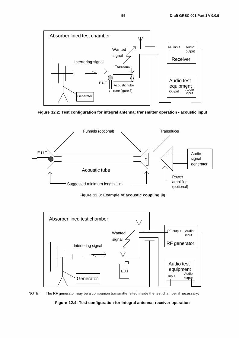
55 Draft GRSC 001 Part 1 V 0.0.9
RF input Audio output
Receiver
Audio test equipment
Absorber lined test chamber
Audio input Output
Interfering signal
Wanted signal
E.U.T.
Transducer
Acoustic tube (see figure 3)
Generator
Figure 12.2: Test configuration for integral antenna; transmitter operation - acoustic input
Acoustic tube
Suggested minimum length 1 m
Funnels (optional)
E.U.T.
Transducer
Poweramplifier(optional)
Audiosignalgenerator
Figure 12.3: Example of acoustic coupling jig
RF output Audioinput
Audio testequipment
Absorber lined test chamber
AudioInput output
Interfering signal
Wanted
signal
E.U.T.
RF generator
Generator
NOTE: The RF generator may be a companion transmitter sited inside the test chamber if necessary.
Figure 12.4: Test configuration for integral antenna; receiver operation

56 Draft GRSC 001 Part 1 V 0.0.9
12.1.2.4 Arrangements for test signals at the output of receivers
The provisions of clause 11, subclause 11.1.2.4 shall apply with the following modification.
The audio frequency output of the equipment shall be suitably coupled to the SINAD measuring system outside of the test environment. The characteristics of the SINAD measuring system shall be such that the upper -3 dB frequency of its detector part is to exceed 16 kHz, and its electrical measurement flatness error between 40 Hz and 16 kHz is not to exceed ±2 dB. The coupling means actually used shall be recorded in the test report.
In the case of systems with a digital audio output a suitable test fixture to convert from digital to analogue signals shall be defined by the applicant. The applicant shall provide details on the interface and test fixture used for the test. The interface must be capable to reach the specifications from above subclause.
12.1.2.5 Arrangements for testing transmitter and receiver together (as a system)
The provisions of clause 11, subclause 11.1.2.5 shall apply.
In case of digitally modulated systems, the applicant shall define suitable test fixtures for converting from the analogue to the digital domain and vice versa. This definition shall be included in the test report.
12.1.3 Exclusion bands The provisions of clause 11, subclause 11.1.3 shall apply.
12.1.3.1 Receiver and receivers of transceivers exclusion band
The exclusion band for receivers and receivers of transceivers is the frequency range determined by the switching range, as declared by the manufacturer, extended as follows:
1) Category 1 and 2 equipment (as defined in subclause 12.3):
• the lower frequency of the exclusion band is the lower frequency of the switching range, minus 5 % of the centre frequency of the switching range;
• the upper frequency of the exclusion band is the upper frequency of the switching range, plus 5 % of the centre frequency of the switching range.
2) Category 3 equipment (as defined in subclause 12.3):
• the lower frequency of the exclusion band is the lower frequency of the switching range, minus 5 % of the centre frequency of the switching range, or minus 10 MHz, whichever will result in the lowest frequency;
• the upper frequency of the exclusion band is the upper frequency of the switching range, plus 5 % of the centre frequency of the switching range, or plus 10 MHz, whichever will result in the highest frequency.
The manufacturer shall state the category of equipment on the documentation accompanying the product, and shall declare the category to the test house in the form of a manufacturer's declaration.
12.1.3.2 Transmitter exclusion band
The lower frequency of the exclusion band is the lower frequency of the switching range, minus 5 % of the centre frequency of the switching range.
The upper frequency of the exclusion band is the upper frequency of the switching range, plus 5 % of the centre frequency of the switching range.

57 Draft GRSC 001 Part 1 V 0.0.9
12.1.4 Narrow band responses of receivers The provision of clause 11,sub clause 11.1.4 shall apply.
The identification criterion for narrow band responses of the EUT is a reduction of the observed SINAD level of the audio output below the relevant category limit set out in table 12.2, see subclause 12.3.2.
The nominal frequency offset used for the identification of narrowband responses shall be twice the bandwidth of the receiver IF filter immediately preceding the demodulator, as declared by the manufacturer, for the first part of the identification procedure, and two and one half times the bandwidth of the receiver for its second part.
For digital systems the narrowband response shall be limited to less than 3 times the declared bandwidth (B) of the system.
12.1.5 Normal test modulation
12.1.5.1 Transmitters
The transmitter shall be modulated with a sinusoidal audio frequency signal of 1 000 Hz, provided either by a suitable acoustic coupling means or by a shielded transmission line (e.g. a coaxial cable). The level of this audio signal shall be adjusted corresponding to 100 % audio modulation (maximum channel loading) of the wanted RF carrier.
For digitally modulated systems the applicant shall specify the modulation method and its parameters and provide a suitable test fixture to allow for testing similar to 100 % audio modulation level.
12.1.5.2 Receivers
The receivers wanted RF input signal shall be set to the operation frequency of the receiver within the designated operation frequency band and modulated with a sinusoidal audio frequency of 1 000 Hz, provided either by a test antenna located within the test environment (integral antenna receivers) or a shielded transmission line such as a coaxial cable (non-integral antenna receivers). The level of the modulation signal shall be adjusted resulting in 100 % audio modulation (maximum channel loading) of the receivers wanted RF input signal.
For digitally modulated systems the applicant shall specify the modulation method and its parameters and provide a suitable test fixture to allow for testing similar to 100 % audio modulation level.
12.2 Performance assessment
12.2.1 General The provision of clause 11, subclause 11.2.1 shall apply with the following modification.
In addition, the manufacturer shall at the time of submission of the equipment for test, supply the following information to be recorded in the test report:
- the applicable equipment category (category 1, 2 or 3) according to subclause 12.3;
- the coupling means to be used for the application of the modulation signal to the EUT and for monitoring the output of the EUT; and
- the level and make up of the RF test signal for the establishment of the communications link;
- description of test fixtures, e.g. for converting from the analogue to the digital domain or vice versa.

58 Draft GRSC 001 Part 1 V 0.0.9
12.2.2 Equipment which can provide a continuous communications link
The provision of clause 11, subclause 11.2.2 shall apply.
12.2.3 Equipment which does not provide a continuous communications link
The provision of clause 11, subclause 11.2.3 shall apply.
12.2.4 Ancillary equipment The provision of clause 11, subclause 11.2.4 shall apply.
12.2.5 Equipment classification The provision of clause 11, subclause 11.2.5 shall apply.
12.3 Performance criteria The product family of wireless microphones, similar RF audio link equipment, cordless audio, in-ear monitoring and associated ancillary equipment is divided into three categories of equipment, each having its own set of performance criteria.
- Category 1 equipment comprises wireless microphones, similar RF audio link equipment, and associated ancillary equipment intended for professional applications.
- Category 2 equipment comprises consumer wireless microphones, cordless audio devices, in-ear monitoring devices and associated ancillary equipment intended for domestic entertainment.
- Category 3 equipment comprises consumer wireless microphones, cordless audio, wireless headphones and associated ancillary equipment intended for general consumer purposes.
- The information required to enable use in accordance with the intended purpose of the product, declared as "professional applications" (Category 1), "domestic entertainment" (Category 2), or "general consumer" (Category 3), shall be contained in the accompanying user product documentation or.
The establishment of the communication link at the start of the test, its maintenance and the assessment of the recovered signal (e.g. audio output) are used as the performance criteria for the evaluation of the essential functions of the equipment during and after the test.
The performance criteria A, B, and C set out in table 1 shall be used in the following manner:
- performance criteria A for immunity tests with phenomena of a continuous nature;
- performance criteria B for immunity tests with phenomena of a transient nature;
- performance criteria C for immunity tests with power interruptions and voltage dips exceeding a certain period of time.

59 Draft GRSC 001 Part 1 V 0.0.9
12.3.1 General performance criteria The equipment shall meet the performance criteria specified in table 12.1, as detailed in the special performance criteria in subclause 12.3.2, 12.3.3, or 12.3.4, as appropriate.
Table 12.1: General performance criteria
During test After test Criteria
Operate as intended; Degradation of performance (see note 1); No loss of function.
Operate as intended; No degradation of performance (see note 2); No loss of function.
A
Loss of function (one or more). Operate as intended; No degradation of performance (see note 2); Functions self-recoverable.
B
Loss of function (one or more). Operate as intended; No degradation of performance (see note 2); Functions recoverable by the operator.
C
NOTE 1: Degradation of performance during the test is understood as a degradation to a level not below a minimum performance level specified by the manufacturer for the use of the apparatus as intended. In some cases the specified minimum performance level may be replaced by a permissible degradation of performance.
If the permissible degradation of performance is not specified by the manufacturer, then this may be derived from the product description and documentation (including leaflets and advertising) and what the user may reasonably expect from the apparatus if used as intended.
NOTE 2: No degradation of performance after the test is understood as no degradation below a minimum performance level specified by the manufacturer for the use of the apparatus as intended. In some cases the specified minimum performance level may be replaced by a permissible degradation of performance. After the test no change of actual operating data or user retrievable data is allowed.
If the minimum performance level or the permissible degradation of performance is not specified by the manufacturer, then either of these may be derived from the product description and documentation (including leaflets and advertising) and what the user may reasonably expect from the apparatus if used as intended.
12.3.2 Performance criteria for equipment which provides a continuous communication link
The establishment of the communications link at the start of the test, the maintenance of the communications link and the assessment of the recovered signal information, e.g. an audio signal, shall be used as the performance criteria to ensure that the essential functions of the transmitter and/or receiver are evaluated during and after the test.
The equipment shall meet the minimum performance criteria as specified for the appropriate category of equipment in subclauses 12.3.2.1 and 12.3.2.2.
12.3.2.1 Performance criteria for Continuous phenomena applied to Transmitters (CT) and Receivers (CR)
The following performance criteria for continuous phenomena apply for transmitters (CT) and receivers or receiver parts of simplex or duplex transceivers (CR) permitting the establis hment of a continuous communications link:
- before the test it shall be verified that the EUT, when coupled through the test equipment and not subjected to EMC stress is capable of producing a SINAD figure of at least 3 dB above the category limit specified in table 12.2;
- during each individual exposure in the test sequence it shall be verified, by appropriate means supplied by the manufacturer, that the communications link is maintained;
- at the conclusion of the test the EUT shall operate as intended with no loss of user control functions or stored data, as declared by the manufacturer, and the communications link shall have been maintained during the test.

60 Draft GRSC 001 Part 1 V 0.0.9
During and after the tests the audio output shall be monitored and assessed. During the test, the SINAD of the audio output shall not result in levels below the relevant category limit specified in table 12.2. After the test, the SINAD shall recover to that level recorded before the test or at least to levels not below the relevant category limit specified in table 12.2.
Table12.2: Continuous phenomena, minimum performance criteria
Equipment category Minimum performance criterion
Intended use
Category 1 30 dB SINAD Professional applications Category 2 20 dB SINAD Domestic entertainment Category 3 6 dB SINAD General consumer
Where the EUT is a transmitter only, and a stand-by mode of operation is provided, the tests shall be repeated with the EUT in stand-by mode of operation to ensure that unintentional transmission does not occur.
Where the EUT is a transceiver, under no circumstances shall the transmitter operate unintentionally during the test.
12.3.2.2 Performance criteria for Transient phenomena applied to Transmitters (TT) and Receivers (TR)
The following performance criteria for transient phenomena apply for transmitters (TT) and receivers or receiver parts of simplex or duplex transceivers (TR) permitting the establishment of a continuous communications link:
- before the test it shall be verified that the EUT, when coupled through the test equipment and not subjected to EMC stress is capable of producing a SINAD figure of at least 3 dB above the category limit specified in table 12.2.
- at the conclusion of each exposure in the test sequence the EUT shall operate with no user noticeable loss of the communications link;
- at the conclusion of the total test comprising of a series of individual exposures the EUT shall operate as intended with no loss of user control functions or stored data, as declared by the manufacturer, and the communications link shall have been maintained during the test.
After the tests the audio output shall be monitored and assessed. After the test the SINAD shall recover to that level recorded before the test or at least to levels not below the relevant category limit specified in table 12.2.
Where the EUT is a transmitter only, and a stand-by mode of operation is provided, the tests shall be repeated with the EUT in stand-by mode of operation to ensure that unintentional transmission does not occur.
Where the EUT is a transceiver, under no circumstances shall the transmitter operate unintentionally during the test.
12.3.3 Performance criteria for equipment which does not provide a continuous communication link
The provisions of clause 11, subclause 11.3.3 shall apply with the following modifications.
For immunity tests with continuous phenomena, equipment not permitting the establishment of a continuous communications link and ancillary equipment intended to be tested on a stand alone basis shall meet the following performance criteria:
- performance criteria A for category 1 equipment;
- performance criteria C for categories 2 and 3 equipment;
as specified in table 12.1.

61 Draft GRSC 001 Part 1 V 0.0.9
For immunity tests with transient phenomena, equipment not permitting the establishment of a continuous communications link and ancillary equipment intended to be tested on a stand alone basis shall meet the performance criteria B as given in table 12.1, except for immunity tests with voltage dips and interruptions (see clause 11, subclause 11.6.7), where it is explicitly stated that the communications link need not be maintained in which case performance criteria C from table 12.1 shall apply.
12.3.4 Performance criteria for ancillary equipment tested on a stand alone basis
The provision of clause 11, subclause 11.3.4 shall apply.
12.4 Applicability overview
12.4.1 Emission
12.4.1.1 General
Clause 11, table 11.2, contains the applicability of EMC emission measurements to the relevant ports of radio and/or associated ancillary equipment.
12.4.1.2 Special conditions
The following special conditions set out in table 12.3, relate to the emission test methods used in clause 11, subclause 11.5.
Table 12.3: Special conditions for EMC emission measurements
Reference to clauses in clause 11 Special product-related conditions, additional to or modifying the test conditions in clause 11, subclause 11.5
11.5.1 Test configuration; Methods of measurement and limits for EMC emissions
The radio equipment shall be operated on one channel frequency, which is close to the middle of the switching range declared by the manufacturer. In transmit mode of operation, the transmitter shall be operated to obtain its maximum rated RF power.
11.5.3.2 Test method; DC power input/output ports
The measurement frequency range extends from 150 kHz to 30 MHz, excluding the transmitter exclusion band in transmit mode of operation. The limits for conducted emissions apply for all modes of operation of the EUT.
11.5.4.2 Test method; AC mains power input/output ports
The measurement frequency range extends from 150 kHz to 30 MHz, excluding the transmitter exclusion band in transmit mode of operation. The limits for conducted emissions apply for all modes of operation of the EUT.
12.4.2 Immunity
12.4.2.1 General
Clause 11, table 11.3, contains the applicability of EMC immunity measurements to the relevant ports of radio and/or associated ancillary equipment.

62 Draft GRSC 001 Part 1 V 0.0.9
12.4.2.2 Special conditions
The following special conditions set out in table 12.4, relate to the immunity test methods and performance criteria used in clause 11, subclause 11.6.
Table 12.4: Special conditions for EMC immunity tests
Reference to clauses in clause 11 Special product-related conditions, additional to or modifying the test conditions in clause 11, subclause 11.6
11.6.1 Test configuration; Test methods and levels for immunity tests
For immunity tests of transmitters, the transmitter shall be operated at its maximum rated RF output power. The immunity tests shall be performed with the EUT successively set to all modes of operation available for the EUT.

63 Draft GRSC 001 Part 1 V 0.0.9

64 Draft GRSC 001 Part 1 V 0.0.9
Annex A (normative): Measurement of Necessary Bandwidth (BN)
NOTE: If the EUT incorporates ancillary coding or signalling channels, for example, pilot tone, etc. these should be switched on prior to measuring the transmitter RF output spectrum.
Figure A.1

65 Draft GRSC 001 Part 1 V 0.0.9
Annex A
List of receiver parameters to be considered and their impact on spectrum efficiency
in the case of poor receiver performance
Receiver parameters Impact on spectrum utilisation and efficiency of radioequipment with poor receiver characteristics
Sensitivity
increase of number of transmitters (base stations)
increase of transmitter power
increased spectrum demand if number of transmitter and transmitter power can not be changed
increased difficulty to elaborate channel plans
_ more interference to other services
_ capacity loss and therefore an inefficient spectrum use
_ influence to public health ("electrosmog")
Blocking, desensitisation, spurious response, protection ratio, co-channel rejection, receiving mask, selectivity, adjacent band rejection,
decrease of number of transmitters of the interfering service and
decrease of transmitter power of the interfering service
_ capacity loss for the interfering service and consequently more spectrum for the other service
_ increase of the interference probability to the wanted radio service
Intermodulation rejection
_ more spectrum is required to allow channel planning to avoid intermodulation products
Cross-modulation rejection
Applies to systems with an AM component only:
requires increased received signal so impacts on transmit power
Note : each of these factors are interrelated and needs to be analysed and quantified in detail. The lack of recommended receiver parameter limits prevent optimised spectrum engineering, leading to the adoption of increased guard bands, greater transmitter powers, smaller cell sizes and less efficient spectrum utilisation. The administration has to use greater safety factors than are otherwise feasible, and the necessity to use these factors may well lead to greater ecological impacts from publicly required radio systems than would otherwise be the case.

66 Draft GRSC 001 Part 1 V 0.0.9
Annex B (normative): Clauses and/or subclauses of the present document relevant for compliance with the essential requirements of EC Council Directives
Table B.1: Clauses and/or subclauses of the present document relevant for compliance with the essential requirements of EC Council Directives
Clause/clause number and title
Corresponding article of Council Directive
89/336/EEC
Corresponding article of Council Directive
1999/5/EC 11.5 Methods of measurement and limits for EMC
emissions
11.5.2 Enclosure of ancillary equipment measured on a stand alone basis
4 (a) 3.1 (b)
11.5.3 DC power input/output ports 4 (a) 3.1 (b) 11.5.4 AC mains power input/output ports 4 (a) 3.1 (b) 11.5.5 Harmonic current emission
(AC mains input port) 4 (a) 3.1 (b)
11.5.6 voltage fluctuations and flicker (AC mains input ports)
4 (a) 3.1 (b)
11.5.7 Telecommunication ports 4 (a) 3.1 (b) 11.6 Test methods and levels for immunity tests 11.6.2 Radio frequency electromagnetic field
(80 MHz to 1 000 MHz and 1 400 MHz to 2 000 MHz)
4 (b) 3.1 (b)
11.6.3 Electrostatic discharge 4 (b) 3.1 (b) 11.6.4 Fast transients common mode 4 (b) 3.1 (b) 11.6.5 Radio frequency common mode 4 (b) 3.1 (b) 11.6.6 Transients and surges in the vehicular
environment 4 (b) 3.1 (b)
11.6.7 voltage dips and interruptions 4 (b) 3.1 (b) 11.6.8 Surges, line to line and line to ground 4 (b) 3.1 (b)

67 Draft GRSC 001 Part 1 V 0.0.9
Annex C (informative): Examples of wireless microphones, cordless audio, in-ear monitoring and similar RF audio link equipment within the scope of the present document
C.1 Wireless radio microphone equipment Wireless radio microphone equipment operates with a continuous RF output signal and normally is in continuous operation for a number of hours. The modulation can be analogue or digital . The transmitter typically operates at a maximum RF output power of 50 mW. Wireless radio microphones are intended for professional use at theatres, shows, broadcast etc. and may be distinguished from other voice or speech communication equipment (e.g. PMR) by the following operational characteristics:
- wider audio bandwidth;
- higher audio signal to noise ratio;
- lower audio frequency distortion.
Aids for the handicapped, tour guides systems, in-ear monitoring and similar constant RF devices operate in a similar manner to wireless microphones, but with variations of bandwidth and a reduced RF output power and possibly reduced quality of speech or voice signal transmission.
Consumer microphones are intended for domestic and consumer use in the band 863 MHz to 865 MHz. They are intended for unlicensed operation at 10 mW erp .The present document applies to consumer microphones and in-ear monitoring equipment as defined in this document: Cordless audio devices in the range 25 MHz to 2 000 MHz, Consumer radio microphones and in ear monitoring systems in the CEPT harmonized band 863 MHz to 865 MHz.
Digital radiomicrophones are intended for professional applications such as theatres , onstage, broadcast etc. in the band 1 785 MHz to 1 800 MHz. The present document applies to digital radiomicrophones as defined in EN 301 840-1: digital wireless microphones in the 1 785 MHz to 1 800 MHz frequency range.
C.2 Cordless audio equipment Cordless audio equipment encompasses radio linked headphones and loudspeakers. The transmitters may be installed in a building, fitted in a vehicle or body worn. The term cordless is also used to describe infra red and other non-RF "wireless" links, but in the context of the present document it is restricted to RF operating systems only. Stereo analogue or digital equipment can be designed for required channel bandwidths of 300 kHz however multichannel equipment for e.g. surround sound systems may need higher bandwidths 600 kHz or 1 200 kHz as described in EN 301 357-1.
In this class of operation, following applications can be identified (non-exhaustive list)
- cordless loudspeakers: Cordless loudspeakers are used in a domestic or consumer environment and are used to allow wireless operation from audio or TV systems and alike.
- wireless headphones: Wireless headphones are used in a domestic or consumer environment to allow wireless operation for audio and TV and alike.
- in-ear monitoring: In-ear monitoring equipment is used by stage and studio performers to receive personal fold back (monitoring) of the performance. This can be just their own voice or a complex mix of sources. This equipment is usually stereo or 2 channel audio.

68 Draft GRSC 001 Part 1 V 0.0.9
- personal cordless: Personal cordless transmitters are to enable the body worn personal stereo equipment to be wire free.
- in-vehicle cordless: In vehicle systems are used for private listening in automobiles and other methods of transport (where permitted).
- broadband multichannel applications: Broadband multichannel systems are used for the transmission of high quality digital audio. These can e.g. surround sound systems or low/uncompressed audio. They are intended to be used in spectrum above 1 GHz and use bandwidths of typically 600 kHz or 1 200 kHz.
C.3 RF audio link equipment covered within the scope of the present document
Wireless audio links are intended for professional use and operate at high RF power levels to bridge more operating range distance in outdoor use. They are used in spectrum identified by the National administration (licensed). The present document applies to RF audio link equipment as defined in EN 300 454-1 operating in the 25 MHz to 3 GHz frequency range, and associated ancillary equipment.

69 Draft GRSC 001 Part 1 V 0.0.9
Annex D (normative): Acoustic stimulation of wireless radio microphones and similar radio communications link equipment, conditions for the test set up and configuration
D.1 General This annex defines the methods of stimulating the EUT when carrying out the necessary EMC tests specified in the present document, in recognition of the rather unusual nature of radio microphones, as compared with the generality of radio products.
Radio microphones vary enormously in their sensitivity and acoustic directivity of their microphones.
In testing wireless radio microphones, it should be borne in mind that many products employ companding techniques.
In the event of difficulty, or uncertainty about the characteristics of the sample submitted for the EMC conformity testing, discussion with the manufacturer is encouraged.
D.2 Audio excitation As part of the EMC test sequence specified in the present document it is necessary to provide an audio excitation signal to the microphone transducer. This may be achieved in at least two ways, as follows:
1) by means of an electro-acoustic resonator (in order to avoid distortion of the calibrated field, this shall be placed outside the physical area of calibration, and be non-metallic); or
2) by means of an acoustic tube (this may be rigid or flexible, but shall have an acoustically "hard" wall, be of non-conducting material, and be of constant inner diameter throughout its length).
The driver transducer shall be large enough, and excited strongly enough, to be able to deliver sufficient sound pressure at the microphone to fully excite the EUT's modulator. Overdrive shall however be avoided.
The driver transducer shall be placed well away from the EUT's microphone, (because it will ordinarily be a moving coil magnetic type), in order to avoid inter-transducer magnetic coupling, and in order to avoid distortion of the electromagnetic test field.
Coupling to the driver transducer, and to the EUT's microphone transducer, may be by means of funnels or other appropriate means. The attachments shall be fixed and firm throughout the test sequence.
When the transducer is coupled to the EUT by means of an acoustic tube, bends in the tube shall be avoided or minimized. Any bends in the tube shall always have a radius that is large in relation to the inner diameter of the tube. Standing waves in the tube may be overcome by lightly packed cotton wool damping pads placed at 150 mm intervals along the length of the tube. It is recommended that the driver transducer is located inside the test chamber, thus minimizing the length of the tube.
NOTE: In trials of this test method a tube length of 1m has been successfully used. The tube was 12,5 mm bore plastic reinforced water hose. The driver transducer was a 75 mm car radio speaker, with a large ferrite magnet, capable of cone movement exceeding 10 mm peak-to-peak. The driver was coupled into the pipe by means of a domestic plastic funnel.

70 Draft GRSC 001 Part 1 V 0.0.9

71 Draft GRSC 001 Part 1 V 0.0.9

72 Draft GRSC 001 Part 1 V 0.0.9
History
Document history
Edition 1 April 2003 1st Draft presented to the GSC in Montreal.
Edition 2 October 2003 Completion of 2nd Draft Sophia Antipolis.
Edition 3 October 2003 Partial completion of Secretarial actions Sophia Antipolis
Edition 4 October 2003 Completion of Secretarial actions post meeting.
Edition 5 December 2003 Sent for Meeting comment
Edition 6 February 2004 Secretarial editorial revisions
Edition 7 February 2004 Annex’s B & C moved to main body of standard
Edition 8 March 2004 Addition of new spectrum mask and test method
Edition 9 April 2004 Addition of units spectrum mask Y Axis (ordinate)