gm c4500/c5500 4x2 stabilizer bar re-installation … · 3 2. removal and re-installation 1....
TRANSCRIPT

070918 80001419
Questions? Contact this Professional Installer :
Company : _________________________________________
_________________________________________
Phone : _________________________________________
Installer : ________________________ Date : __________
GM C4500/C5500 4X2
STABILIZER BAR RE-INSTALLATION KIT
2003-NEWER MODELS For Installation with 8M000070, 8M000078, & 8M000080
UltraRide Suspensions
Link Kit Part Number: 800M0134
OW
NE
RS
MA
NU
AL

2
1. INTRODUCTION
IMPORTANT! Read through the entire installation instructions thoroughly before proceeding with suspension installation.
IMPORTANT! This ULTRARIDE® GM 4500/5500 4X2 STABILIZER BAR RE-INSTALLATION KIT REQUIRES the Original Equipment (OE) rear stabilizer bar option, RPO code GN1 or GS4. Stabilizer bar components are supplied with the OE stabilizer bar option that are not provided in the UltraRide kit. See Fig. 1-1 for details. The re-installation is recommended to be performed during the UltraRide Suspension installation.
The ULTRARIDE GM 4500/5500 4X2 STABILIZER BAR RE-INSTALLATION KIT is intended to be used only with these Link UltraRide Air Suspensions:
� 8M000070
� 8M000078
� 8M000080 When installing certain UltraRide suspensions, re-installing the OE stabilizer bar would result in de-creased rear ground clearance. The stabilizer bar provided in this kit has ground clearance equal to the clearance present on the OE leaf spring suspension.
The ULTRARIDE GM 4500/5500 4X2 STABILIZER BAR RE-INSTALLATION KIT
1. (1) 1 3/4” Diameter Stabilizer Bar
2. (1) Driver Side Stabilizer Bar Frame Mount Bracket
3. (1) Passenger Side Stabilizer Bar Frame Mount Bracket
4. (8) 7/16 X 1 1/4 Flanged Bolts
5. (8) 7/16 Top Lock Flanged Nuts
6. This Instruction Manual
FIG. 1-1 ULTRARIDE® STABILIZER BAR
OE MOUNT BRACKET - NOT SUPPLIED IN KIT
OE CONNECT-ING LINK - NOT
SUPPLIED IN KIT OE REAR BRACKET AND BUSHING - NOT
SUPPLIED IN KIT
FRAME MOUNT BRACKET AND HARDWARE
FRONT HANGER

3
2. REMOVAL AND RE-INSTALLATION
1. Uninstall OE STABILIZER BAR by removing (4) OE FRONT MOUNT BOLTS and (4) OE REAR BRACKET BOLTS from both sides. Discard the FRONT fasteners, and save the REAR fasteners for later use. The OE STABILIZER BAR should be separated from the vehicle chassis. See Fig. 2-1 and 2-2.
2. Remove the OE REAR BRACKETS and BUSHINGS from the OE STABILIZER BAR. Also remove the OE CONNECTING LINK from the STABILIZER BAR. See Figure 2-1, 2-2 and 2-3.
3. Re-install the components removed in Step #2 to the LINK STABILIZER BAR supplied in this kit. Torque the CONNECTING LINK nuts to 150 FT-LBS. See Fig. 2-4.
4. If frame holes for the FRAME MOUNT BRACKET are not present to the rear of the UltraRide® FRONT HANGER, the (4) Ø0.50” required holes must be drilled, (2) on each side. See Fig. 2-5 for hole location. A paper template is provided on Page 6 of this instruction manual. If desired, the paper template can be traced onto a sturdier material, such as cardboard or metal, to facilitate use. If the hole needed to locate the template is not present, the hole pattern on the template should be drilled 1.0” outboard from the edge of the main frame flange.
5. Install both FRAME MOUNT BRACKETS to the frame with (4) 7/16 FLANGED BOLTS and (4) 7/16 FLANGED NUTS. Orient the brackets as shown in Fig. 1-1 and 2-6. Torque the nuts to 45 FT-LBS.
6. Install both REAR BRACKETS of the STABILIZER BAR to the axle mounting location, using the OE bolts and nuts (if applicable). A small jack, placed under the REAR BRACKET, will help hold the bar and components in place. Torque the REAR BRACKET BOLTS to 35 FT-LBS.
7. Install both OE FRONT MOUNT BRACKETS, currently attached only to the STABILIZER BAR, to the FRAME MOUNT BRACKETS. Use the provided (4) 7/16 FLANGED BOLTS and (4) 7/16 FLANGED NUTS to connect the brackets. Before tightening the bolts, verify the OE FRONT MOUNT BRACKET is aligned vertically. Torque the nuts to 45 FT-LBS.
8. Double-Check all fastener joints are tightened to the appropriate Torque. A good practice is to use a paint marker to mark each fastener across the nut and bolt threads as it is tightened. This practice gives a visual check later that all fasteners were properly tightened.
FIG. 2-1
REMOVE BRACKETS FROM FRAME & DIS-CARD FASTENERS
REMOVE & SAVE REAR COMPONENTS
FIG. 2-2
SAVE OE CONNECT-ING LINK NUTS

4
FIG. 2-3
COMPONENT REMOVAL COMPLETE—SAVE LABELED PARTS FOR RE-USE
OE REAR BUSHINGS
OE CONNECTING LINK NUT
OE CONNECTING LINKS
OE REAR BRACKETS
OE CONNECTING LINK NUT
FIG. 2-4
COMPONENT RE-INSTALLATION ON KIT STABILIZER BAR COMPLETE
ULTRARIDE® STABILIZER BAR SUPPLIED IN KIT

5
FIG. 2-6
DRIVER SIDE FRAME MOUNT BRACKET AND HAREWARE
PASS. SIDE FRAME MOUNT BRACKET AND HARDWARE
DRIVER SIDE FRAME HOLE TEMPLATE LOCATION & ORIENTATION
FIG. 2-5
FRAME HOLE TEMPLATE
FRAME MOUNT BRACKET
CONNECTING LINK
STABILIZER BAR
DRILL (2) FRAME HOLES HERE IF
NEEDED. REPEAT ON PASS. SIDE.

6
7
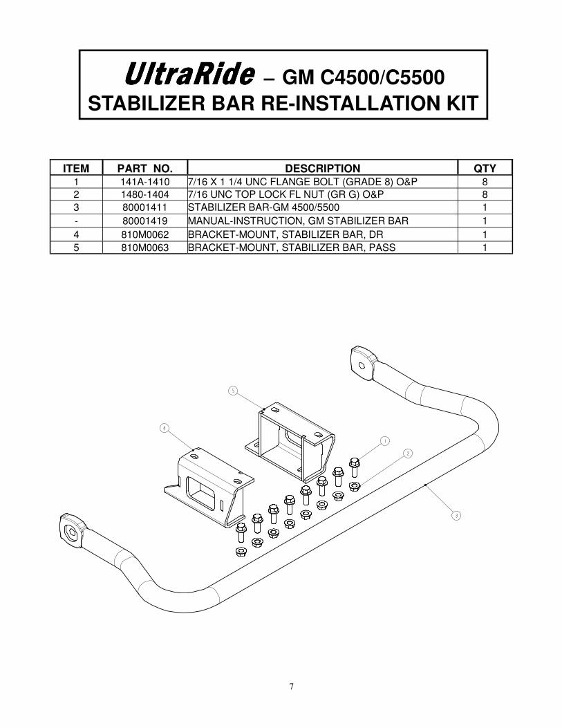
UltraRideUltraRideUltraRideUltraRide — GM C4500/C5500
STABILIZER BAR RE-INSTALLATION KIT
ITEM PART NO. DESCRIPTION QTY 1 141A-1410 7/16 X 1 1/4 UNC FLANGE BOLT (GRADE 8) O&P 8
2 1480-1404 7/16 UNC TOP LOCK FL NUT (GR G) O&P 8
3 80001411 STABILIZER BAR-GM 4500/5500 1
- 80001419 MANUAL-INSTRUCTION, GM STABILIZER BAR 1
4 810M0062 BRACKET-MOUNT, STABILIZER BAR, DR 1
5 810M0063 BRACKET-MOUNT, STABILIZER BAR, PASS 1

8
Link Mfg. Ltd. 223 15th St. NE
Sioux Center, IA USA 51250-2120
(712) 722-4874
http://www.linkmfg.com/