gmm 1&c chapter 4 - uss oklahoma city 1 and c chapter 4 loading... · chapter 4 loading,...
TRANSCRIPT

CHAPTER 4
LOADING, UNLOADING, AND DUD-JETTISONING
The preceding course of this series and the
preceding chapter of this course gave you an
overview of guided missile launching systems. The
control panels operated by GMMs were described.
The functioning cycles in three types of operation-
automatic, step, and emergency were explained,
and crew stations were illustrated.
LOADING is the process of bringing the round
from the magazine, attaching any additional parts
necessary (wings, fins, power supply, arming
plug), and placing the complete missile on the
launcher, ready for firing.
UNLOADING the missile consists of returning
the round to the magazine or to a container for off-
loading. Wings and fins have to be folded or
removed, the arming plug and the thermal batteries
removed, and the round stowed in the magazine, in
the cell or tray designated for it (or packed in its
container for shipment).
Since most of the work is done automatically by
launching system, and lower rated men do most ,of
the assembling and disassembling,. what does the
GMM 1 or C do? He may operate a control panel,
supervise the work of the assembly team, act as a
safety observer, troubleshoot the equipment, and
make the more difficult repairs, including overhaul
and adjustment of equipments.
You need to become completely familiar with,
the system or systems you have on board, but you
also need to know about other types of systems.
This chapter emphasizes the role of the GMM 1
and C in loading and unloading missiles, and goes
into detail on the operation of the dud-jettisoning
methods for the different missiles in
use on Navy ships. The quals relating to dud
jettisoning are listed for lower grades, but you have
the responsibility for supervising the activity. The
decision to jettison a missile is made by higher
authority.
TERRIER MISSILE SYSTEM
Each side of the Terrier launcher is serviced by a
complete and independent loading system, and
each of these systems is serviced by a
corresponding handling system. Except for some
minor differences, the operation of the two sides is
identical. The installation on different ships
accounts for other variations; the mark differences
account for the greatest variations; mod changes
may be simple ones. The changes required to
accommodate the Asroc missile in the Mk 10 Mods
7 and 8, however, are more than minor although
the principles of operation remain the same.
LOADING
The location of the loader in the Terrier
launching system is pointed out in figure 2-8.
Figure 3-8 points out the location of the loader
power drive, and the loader rail view port. Table 3-
1 shows that the Mk 8 loader has been used on Mk
9 and Mk 10 Terrier launching systems, with
modifications. Ready service rings are identified in
both of the above illustrations for the Mk 10
system. The comparable component in the Mk 9
system, the magazine cell rack, is shown in figure
3-5. The three ready service rings of the Mod 7 and
Mod 8 were shown in the preceding course,
Gunner's Mate M (Missiles) 3, & 2, NAVTRA
10199.
82

CHAPTER 4 - LOADING, UNLOADING, AND DUD-JETTISONING
The feeder includes the loader, the magazine
and/or ready service rings, and the assembler, each
with its components.
The sequence of steps in moving a round from
the magazine to the launcher was given in chapter
3 for Mk 9 and Mk 10 launching systems. If you
have had duty on a ship with Terrier capability
these steps are familiar to you. If your experience
has been with other missile systems, you will
recognize the similarities. Now you need to know
the launching system so well that you can explain it
to lower rated men, and can direct and supervise
their work in the loading process. The only manual
work involved (if everything is working OK) is the
assembling of the wings and fins in the assembly
room. If any part of the system fails to act
automatically on signal, you need to know how to
find the trouble and correct it. The multiplicity of
parts in the launching system makes this a real
challenge. If you look at the whole complex, it
might seem too intricate to master, but if you
remember it is made up of applications of simple
machines, operated by hydraulic or pneumatic
power, electricity, and electronics, you can
understand it and unravel its problems.
Warn trainees and other nonoperating personnel
in the launching system compartments not to touch
controls. Only authorized personnel are permitted
in the launching system compartments. NO ONE is
permitted in the magazine area when the system is
being operated. New and inexperienced personnel
must not be permitted to work alone, but must be
under direct and continued supervision of skilled,
and experienced personnel. All persons whose
duties involve the operation of, or stationing on or
near power-operated missile equipment, must be
thoroughly familiar with the safety orders and
precautions and operating instructions for that
equipment. As a supervising petty officer, you
must remind your men frequently of the safety
rules and regulations and enforce them. Violation
of safety precautions, willful or accidental, should
be reported at once to the immediate superior.
Safety devices should always be kept in good order
and operative at all times.
The launcher captain monitors the launching
system functions by watching. the indicating lights
on his panel during automatic operation. (The step
control lights and switches on the EP2
panel are covered and are not in operation during
automatic procedure.) He reports any maloperation
of the equipment, by telephone, to the feeder
system captain and the operator of Guided Missile
Status Indicator Mk 81 Mod 0 in weapons control.
Under emergency conditions, or during any
maloperation, the launcher captain stops the
launcher movement with the train and elevation
operation selector switch or with the train and
elevation motor switches.
Grounds are a major cause of casualties,
responsible for damage both to personnel and
ordnance equipment. Particular attention should be
given to watertight integrity of watertight packing,
stuffing tubes, covers on junction boxes, switches,
and all types of exposed equipment, as well as
equipment in areas where condensation can take
place. Damage from moisture is a severe problem
in tropical climates; frequent inspections are
necessary to detect mildew or other signs of
moisture. Other unintentional grounds may be due
to abrasion of insulating material on wires, contact
of exposed wires, or poorly made connections.
Grounding of explosive components, handling
equipment, and containers during handling was
described in chapter 2.
When acting as assembly captain, do not allow
the assemblers to remove wings and fins from the
racks until the missile has stopped in position in the
assembly area. Wait until all the assemblymen
have completed their wing and fin assembly, have
stepped back to the clear area, and have pressed
their safety switches. Then signal the launcher
captain that the assembly area is ready. If a safety
switch is inoperative, or malfunctions in any way,
check to see that all the assemblymen are in the
clear area after completing assembly; then signal
the launcher captain "CLEAR BY-PASS." The
safety switch used by the assemblymen is a foot
switch on some mods, while a hand switch is
provided on others; but each man has one at his
place in the assembly area.
UNLOADING
With some launching systems, all Unloading
must be done in step control (LOCAL or
MANUAL), but automatic unloading is possible
with the Mk 10 launching system. The unload
83

GUNNERS MATE M 1 & C
order is sent by WCS and will indicate the side, A
or B, or both, causing a blinking light to appear on
the launcher captain's panel. The missile may be in
the assembly area or on the launcher when the
unload order is given. The launcher captain
positions the switches on his panel to conform to
the unload orders, and this initiates the automatic
unloading. The launcher synchronizes to load
position and then proceeds through the unloading
steps, the reverse of loading.
When the missile reaches the assembly area, the
wings and fins must be removed and returned to
the racks. During the unload operation, visually
inspect to be sure the wings and fins are removed,
the booster is unarmed, and the missile sustainer is
in the SAFE position before returning the missile
to the magazine area. A dud or misfired booster
being returned to the magazine must not be
removed from the wing and fin assembly area until
the feeder system captain is notified that the
booster and missile sustainer have been checked
and reset to the UNARMED position.
The assembly area is the most dangerous section
of the entire launching system during loading and
unloading operations. It is the responsibility of the
instructor (usually a GMM 1 or C) to ensure that
all safety instructions are strictly adhered to. The
trainees must not be permitted to, operate the
equipment, to position control switches, ot to
perform any other work on the system without
direct and continuous supervision of the instructor.
Although each trainee is responsible for his own
safety, you, as a petty officer, must give frequent
reminders of the safety precautions and be on
constant watch to see that they are observed. When
the feeder system is in operation, the assemblymen
remain on the station with their foot switches
depressed, except during actual assembly or
disassembly of the wings and fills. The operator of
the assembly captain's panel must not give the
READY signal until he is completely sure that
every man has stepped back to the safe area and
has his safety switch depressed. There is an
emergency wing and fin assembly bypass switch
on the panel, but this must NEVER be used except
in case of a malfunctioning foot switch and during
equipment checkout when personnel are clear of
the assembly area.
During continuous firing, there will be missiles
in the assembly area as well as on the launchers.
Before the missile to be unloaded from the
launcher can be moved, the missile in the assembly
area of that side has to be returned to the magazine.
The launcher captain must be VERY SURE that
there is no missile in the assembly area before he
starts the unloading procedure. In automatic
unloading, the launcher captain positions his
unload assembly switch, the assemblymen remove
the wings and fins, the assembly captain positions
the assembly-ready switch on his panel to
REMOVED, and the weapon is moved by the
system mechanisms back to the magazine or ready
service ring.
At the end of the firing, all missiles must be
returned to the magazine before the system is
deactivated.
An unloading cycle is necessary after every
firing of an Asroc missile from a Terrier system
because the adapter must be returned to the
magazine tray.
Step Control Unloading
For checking or maintenance purposes, or in an
emergency, the unloading operation may be carried
out in step control. Step control is always used
when moving the missile-booster combination
from the ready service ring to the checkout area for
routine care and maintenance or for repairing
missiles previously struck down as duds. Step
control must also be used for exercise and
strikedown. The steps are initiated one at a time by
use of the push buttons on the launcher captain's
panel. The launching equipment is always started
in step control. Use the OP for your launching
system, the drawings, and the checklist for the
procedural steps and the designations of the
switches to be activated. The lights and switches on
the control panels are plainly numbered and
labeled, but it smoothes operation if you
familiarize yourself with the panels so there is no
long delay while you search the panel face for the
right button or switch to operate next.
The indicating lights on the launcher captain's
panel show switch actuation. Each pushbutton
contains two light bulbs, separated by a center
divider. One bulb (or one-half of the pushbutton)
corresponds to the A side and the other
84
CHAPTER 4 - LOADING, UNLOADING, AND DUD-JETTISONING
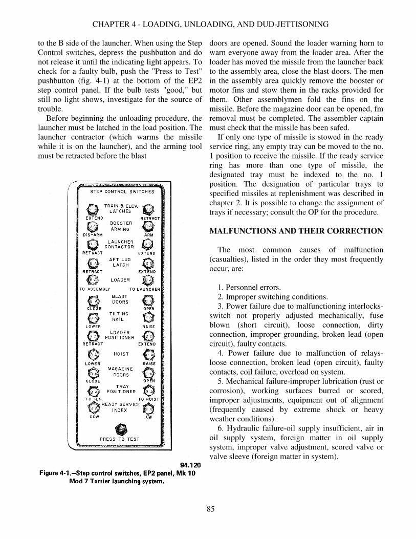
to the B side of the launcher. When using the Step
Control switches, depress the pushbutton and do
not release it until the indicating light appears. To
check for a faulty bulb, push the "Press to Test"
pushbutton (fig. 4-1) at the bottom of the EP2
step control panel. If the bulb tests "good," but
still no light shows, investigate for the source of
trouble.
Before beginning the unloading procedure, the
launcher must be latched in the load position. The
launcher contractor (which warms the missile
while it is on the launcher), and the arming tool
must be retracted before the blast
doors are opened. Sound the loader warning horn to
warn everyone away from the loader area. After the
loader has moved the missile from the launcher back
to the assembly area, close the blast doors. The men
in the assembly area quickly remove the booster or
motor fins and stow them in the racks provided for
them. Other assemblymen fold the fins on the
missile. Before the magazine door can be opened, fm
removal must be completed. The assembler captain
must check that the missile has been safed.
If only one type of missile is stowed in the ready
service ring, any empty tray can be moved to the no.
1 position to receive the missile. If the ready service
ring has more than one type of missile, the
designated tray must be indexed to the no. 1
position. The designation of particular trays to
specified missiles at replenishment was described in
chapter 2. It is possible to change the assignment of
trays if necessary; consult the OP for the procedure.
MALFUNCTIONS AND THEIR CORRECTION
The most common causes of malfunction
(casualties), listed in the order they most frequently
occur, are:
1. Personnel errors.
2. Improper switching conditions.
3. Power failure due to malfunctioning interlocks-
switch not properly adjusted mechanically, fuse
blown (short circuit), loose connection, dirty
connection, improper grounding, broken lead (open
circuit), faulty contacts.
4. Power failure due to malfunction of relays-
loose connection, broken lead (open circuit), faulty
contacts, coil failure, overload on system.
5. Mechanical failure-improper lubrication (rust or
corrosion), working surfaces burred or scored,
improper adjustments, equipment out of alignment
(frequently caused by extreme shock or heavy
weather conditions).
6. Hydraulic failure-oil supply insufficient, air in
oil supply system, foreign matter in oil supply
system, improper valve adjustment, scored valve or
valve sleeve (foreign matter in system).
85

GUNNERS MATE M 1 & C
It is hoped to eliminate (or greatly reduce) many
common failures by conscientious application of
the 3-M System. No hydraulic system, for
example, should be without sufficient oil if a daily
check is made. The greatest cause of trouble will
probably continue to be no. 1, "Personnel errors."
Troubleshooting
In spite of the best preventive maintenance, there
will be some operational failures. The cause of the
trouble may be hard to locate, so you have to trace
it down. The ability to use schematics and wiring
diagrams is essential.
Troubleshooting (casualty analysis) is a very
important part of maintenance. Before starting any
repairs of a system, determine which of the
components is (are) faulty. It frequently happens
that the person doing the troubleshooting finds the
faulty component, replaces it, but fails to locate the
origin of the trouble. The origin of the casualty
must be located before replacing a component,
otherwise the trouble will recur and the new
component will be damaged.
Before performing any casualty analysis or
repair work, you should be thoroughly familiar
with the equipment, the sequence of operations, the
control panels, manual and interlock switches,
indicating lights, mechanical and hydraulic
functions, and the relation of the control system to
the weapons control station. Troubleshooting is
discussed in several chapters in connection with
different types of components. It may require
considerable persistence and patience or it may be
quick and easy, but it should always be methodical
and thorough.
DUD-JETTISONING
Jettisoning of missiles may be necessary in an
extreme emergency or if hazardous conditions
exist, such as fire on deck in the vicinity of the
launcher, or if the weapon is damaged by enemy
action, or if it failed to fire and circumstances do
not permit returning it to the magazine or the
checkout area. DO NOT JETTISON A MISSILE
WITH A NUCLEAR WARHEAD. The
decision to jettison comes from the commanding
officer via the weapons control station.
The dud-jettisoning unit (fig. 4-2) is associated
with each launcher to permit the ejection of missile
rounds from the launcher. Each unit consists of two
ejectors and a control panel (fig. 4-3). The dud-
jettison units are mounted in such a way that
ejection can be performed at approximately 95° or
275° of train and at 34° of elevation. (The train and
elevation are different on each ship.) The launcher
automatically trains and elevates to bring the after
end of the round in line with the dud-jettisoning
ejector, and a pneumatic mechanism in the ejector
elevates a piston in line with the round. The piston
extends slowly, under low pressure air, until its
mushroom-headed piston mates with the after end
of the round, then extends rapidly with a short,
powerful pneumatic stroke (3500psi), forcing the
round off the launcher and over the side.
The control panel for the dud-jettison unit is
mounted in the deckhouse, and is operated by the
launcher captain (or the port side assembler
captain) upon orders from the WCS by sound-
powered telephone. In the Mk 10 Mod 8 system,
the control panel is adjacent to the A-side blast
doors, within the aft compartment. When the ship's
roll exceeds 20°, jettisoning must be performed
only on the downroll. A standard bubble type
inclinometer with a 45° index scale is mounted
next to the dud-jettison control panel to indicate
ship's roll.
The launcher captain initiates jettisoning by
positioning the DUD-JETTISON switch at the EP-
2 panel, which causes the launcher to synchronize
automatically to the dud-jettison position.
The dud-jettisoning procedure may be applied to
a dud missile, a misfired booster, or any other
condition which necessitates a decision to jettison a
weapon.
Operation
Whenever the firing key is depressed, the DUD
and MISFIRE lamps light momentarily, until the
missile has cleared the rails. However, if the
missile is a dud, the DUD lamp continues to be
lighted. The contractor fails to retract. The operator
may try to fire the missile by placing
86

CHAPTER 4 - LOADING, UNLOADING, AND DUD-JETTISONING
the dud switch in the ON position. If this succeeds,
the contactor retracts and the DUD lamp, the RAIL
lamp, the WARMUP TIMER RAIL lamp, and the
READY TO FIRE lamp all go out. When the
arming tool unwinds, the READY lamp also goes
out.
If attempts to fire the missile are unsuccessful, it
may be returned to the magazine for later
inspection and possible repair; its location is
marked on the control panels. In some situations
(emergency or combat), it may be necessary to
jettison a dud missile; wait for the order to do so.
A DUD indication will also occur if the firing
key is released too quickly (before 1.5 seconds
have elapsed). The booster firing relay will not be
energized and as a result a dud missile is left on the
launcher.
OPERATING THE DUD-JETTISON PANEL. -
Suppose jettisoning of a missile has been ordered.
On a Mk 10 launching system the port
side assembler captain mans the dud-jettison panel.
He must have sound-powered telephone
communication established. At the control panel
(fig. 4-3) he opens the positioner air supply valve.
This connects to low pressure air. Next, he rotates
the positioner control lever to POSITION I for a
BT-3 missile or POSITION II for a BW-1, for
ejector side A or B, whichever side is to be used.
When the ejector is in the raised position, rotate the
jettison lever to CHARGE and hold the lever in
this position until the air pressure meter reads 3500
psi. (Pressure requirements for your installation
may be different.) A light ("Safe to Jettison") on
the control panel indicates when the ejector is fully
raised to "Firing Position."
WARNING: Do not cycle below the designated
operating pressure.
Rotate the jettison lever to READY and wait for
the command. Upon receiving the command to
"Jettison," check that the air pressure meter
87

GUNNERS MATE M 1 & C
reads in excess of 3400 psi and rotate the jettison
lever to JETTISON. The head of the ejector is
forced against the missile base by the air pressure
and spring pressure from the spring side of the
firing valve, and the missile is forced overboard
from the launcher. Note that the air pressure drops
rapidly. Lastly, rotate the positioner control lever to
the STOW position. The dud-jettison unit must be
lowered ALL the way before the launcher power
brake can be released and the launcher trained and
elevated for reloading.
There are differences in control panel switches
and nomenclature, but the principles of operation
are very similar. The steps in operation of the dud-
jettison panel on your ship should be posted beside
the panel. On some mods, a metal instruction plate
is permanently fastened to the dud-jettison panel,
directly in front of the operator. After the jettison
operations are completed, the dud-jettison panel
operator moves the lever of the Positioner Air
Supply valve to CLOSED, and the launcher captain
returns control to the EP2 panel by
88

CHAPTER 4 - LOADING, UNLOADING, AND DUD-JETTISONING
repositioning the switches to the desired type of
operation.
If the round is considered dangerous to the ship,
the launcher captain positions his emergency
enabling switch to ENABLE upon telephoned
order from the WCS operator. The WCS operator
then holds down the dud emergency firing switch
until the round leaves the rail (RAIL LOADED
light goes out). This is dud firing (not jettisoning),
and is carried out in WCS without action by the
launching system crew. This method of dud firing
disables one side of the launching system. It is used
only in case of real danger from the missile on the
launcher. This method of dud firing disables one
side of the launching system. It is used only in case
of real danger from the missile on the launcher.
SAFETY RULES FOR DUD JETTISONING. -
Under emergency conditions or during any
maloperation, the launcher captain must stop the
launcher movement with the train and elevation
operation selector switch or with the train and
elevation motor switches.
In case of booster misfire, do not permit
personnel to approach the launcher for at least 10
minutes after the last attempt to fire, and the firing
circuits have been known to be open. The time
limit is at the discretion of the commanding officer
and is not obligatory in time of action.
The return of a dud or a misfired booster to the
magazine, or dud jettisoning, it should not be
started until the firing safety plug in the EP-2
control panel has been removed.
During all operations for disposal of misfires or
dud, the launcher captain should remain at his
control panel to guard the firing safety plug and to
observe and make certain the launcher and the
guide remain in a SAFE and UNLOAD position.
Do not position the emergency enabling switch
to ACTIVATION and ENABLE during firing,
unless specifically ordered to do so by weapons
control. Use caution as to the proper side and the
position ordered.
During unload operations, visually inspect to be
sure that wings and fins are removed, booster is
unarmed, and the missile sustainer is in the SAFE
position before returning the missile to the
magazine area.
A dud or a misfired booster being returned to the
magazine must not be removed from the wing and
fill assembly area until the feeder system captain is
notified that the booster and the missile sustainer
have been checked and reset to the UNARMED
position.
WHAT TO DO WITH ASROC. With the
extensive missile tests and circuitry checkout
required for Asroc missiles, it is not likely that an
Asroc missile will have to be jettisoned, as duds
will be discovered before the missile is placed on
the launcher. If it is necessary to jettison an Asroc
missile, the adapter rail is jettisoned with it. It is
jettisoned in the same manner as a Terrier missile.
If a dud results from loss of synchronization, it
should be handled according to ship's doctrine.
Is It a Dud or a Misfire?
Note the difference between a dud and a misfire.
If the DUD lamp lights on the weapons assignment
console (WAC) when the firing key is pressed,
nothing happens to the missile-it does not transmit
the electrical energy to set off any explosive
components. Except under certain tactical
situations, when the launcher has to be cleared
quickly for firing, the dud missile can be returned
to the magazine for later examination and repair. In
a misfire, some part or parts of the explosive
system were actuated when the missile firing key
was depressed, but not enough to send the missile
off the launcher. A misfire presents a dangerous
situation. If the MISFIRE lamp lights at any time
during the firing cycle, there are three alternatives:
(1) emergency firing procedures may be used; (2)
the launcher may be aimed in a safe direction for a
waiting period prescribed by ship's doctrine. If
nothing happens, the missile may be returned to the
magazine for later examination and repair; or (3)
the round may be jettisoned.
A missile is considered to have misfired when its
booster fails to fire after its electrical and hydraulic
systems have been activated and the booster firing
relay has been energized. When the firing key is
depressed, the DUD lamp lights and the MISFIRE
lamp flashes. When the missile fails to clear the
rail, the MISFIRE lamp continues to flash and the
DUD remains lighted.
89

GUNNERS MATE M 1 & C
You cannot tell whether the explosive train inside
the missile will sputter and go out, or if it will burn
and explode on the launcher, or if it will fire in a
short time. All factors of the situation - known,
calculated, and surmised - have to be considered in
deciding whether to wait and see what happens or
jettison the missile. In a battle situation, it may be
necessary to fire a missile from the other side of
the launcher while leaving the misfire on the first
side. Several attempts may be made to fire the
missile, by means of the emergency firing key.
When the emergency enabling switch is at
NORMAL, the emergency firing key can be held
down as long as desired in an attempt to activate
and fire the missile. If it is placed at
ACTIVATION AND ENABLE, the booster firing
transformer is energized through an alternate
circuit and many of the normal firing relay contacts
are bypassed. If the firing is successful, it shows
the relays were at fault on the first try. If the
missile cannot be fired by this method, most likely
it will have to be jettisoned. Decision must be
made in WCS.
The two emergency firing circuits in the Mk 10
Mod 7 launching system, EMERGENCY
ACTIVATION AND ENABLE, and
EMERGENCY ENABLE, are used only in the
Terrier mode.
Malfunctioning of Dud-Jettisoning Units
The dud-jettisoning unit has been designed to
provide maximum service with a minimum of
maintenance. A major difficulty that may be
experienced with dud-jettisoning units is that of ice
forming in the valve passages. This is caused by
rapid expansion of moist, compressed air. Any
moisture traps in air lines should be drained
regularly. Deicing lines port heated fluid to the
cover door sections to prevent formation of ice
during cold weather, permitting operation of the
jettisoning unit in the most adverse weather
conditions. The anti-icing system which also
protects the launcher from icing.
MAINTENANCE.-Since the dud-jettisoning
unit is intended for emergency use, it must be kept
in operating condition, ready for instant use when
needed. Check out the equipment at:
regular intervals by exercising each dud ejector (no
missiles on launcher rails). Replace indicator lamp
bulbs on the control panels when necessary. The
outside of the panel should be cleaned periodically.
Usually wiping with a dry cloth is enough; a damp,
soapy cloth may be needed .to remove grease spots
or fingerprints. Wipe dry. The dud jettison unit
does not require lubrication. In particular, take care
NOT to lubricate the firing piston head or stem.
WARNING: If it is necessary to disassemble any
of the air lines, be sure the valve in the ship's high
pressure line (4500 psi) is closed, and also the
nearest shutoff valve in the 100-psi ship supply
line. Bleeder valves in the ejector unit
accumulators should be open. Tag all valves while
working. Protect any open ends of pressure lines
with suitable caps or plugs to prevent entry of dirt,
moisture, or other foreign matter.
It may be necessary to replace a gasket on an
ejector unit, or a defective limit switch. The need
for a new gasket may be discovered when checking
the air-charging chamber of the ejector for
hydraulic fluid or moisture. To make the check,
remove the drain plug from the lower end of the
ejector assembly. If there is any drainage, wipe the
drain port clean, check the gasket and plug for
signs of deterioration, and replace if necessary.
Wait at least 2 hours after a unit has been cycled
before making the drainage check. Further
disassembly of ejector units is not contemplated,
short of battle damage.
Air filters and air breathers, of which there are
six: each in the Terrier jettisoning equipment,
require regular inspection to see if they need
cleaning. Cleaning is done by washing the filter or
breather in solvent, rinsing in clear water, and
drying with a stream of compressed air. Never
direct compressed air at yourself or others; it can
be fatal.
Before unscrewing a plug that holds a filter, be
sure the manual shutoff valve on the jettison panel
is closed and that the pneumatic lines leading to the
ejector are vented {JETTISON AND OFF on
panel). (Seer figure 4-3.) There are four of these
plugs (and filters) on the face of the panel.
The sensitive switch assemblies, solenoid
assembly, and dud-jettison synchro-transformer all
need periodic inspection, and adjustment or
replacement as required. The adjustment is
90

CHAPTER 4 - LOADING, UNLOADING, AND DUD-JETTISONING
determined at installation and is not changed later,
but units are brought back into adjustment if they
vary from it. Two sensitive switch assemblies are
located on each ejector. The four solenoid
assemblies are all located in the jettison control
panel. Any malfunctioning parts are replaced. The
synchros are located within the EP2 panel. The
synchro control transformers are adjusted or
replaced. Instructions for this are given in OP2350.
Manual switches are not repaired but are replaced
if they do not function. (The foot-operated safety
switches in the assembly area are an exception.)
These include indicating pushbutton switch
assemblies, pushbutton switch assemblies, toggle
switch assemblies, and rotary switch assemblies
used on control panels.
Maintenance of the electrical cables includes
periodic checking of the cables, connectors, or other
associated components: Measure the insulation
resistance of power supply cables with a megger. A
ground-detection indicator on the EPI panel
continuously monitors the control supply circuit.
Disconnect this indicator before making a megger
test of a cable in the system. If an insulation
breakdown is indicated, trace it down and correct it,
then test again. If a cable is damaged so it requires
replacement, get a spare cable of the same kind from
spare parts stock and install it. Umbilical cables are
always replaced, not repaired. Do not splice a cable
except in an emergency. Attach identification
markers to all cables. All terminal lugs should be
crimped to their connectors.
TESTS.-Maintenance tests are conducted in
cooperation with other ratings and all components of
the missile system are tested. System readiness tests
are performed every day; system maintenance tests
are performed weekly or monthly. Use the OP for
your weapons system when each test is performed.
OP 2629, Volume 3, CLG (Terrier) Guided Missile
and Anti-aircraft Weapon System, Maintenance Test
Procedures (U;C), consists almost entirely of tables
that list the tests to be made. The equipment to be
used, the settings to make on the control panels,
directors, computers, etc., and the response expected
are all given in the tables. Step No. 29 is a test of the
dud-firing circuits. Steps Nos. 27 and 28 are for
misfire circuit testing. Referring to table 3.2, you
find that steps 26,
27, 28, 29 and 30 must be performed weekly and
must be conducted together and in sequence.
Turning to step No. 27 in the table of test
procedures, you find that the EP-3 panel on the
launcher and the weapon assignment console in
the weapons control station must be manned. The
actions to take (buttons to push) and the desired
response for each are listed. Sample log sheets are
shown for recording performance of tests. If any
failure is indicated on the EP-3 panel, obtain the
circuit diagrams of the system, schematics, and
the maintenance instructions for your equipment,
trace the trouble to its source, and correct it. It
may be only a burned-out signal light, or it may
be some trouble very hard to locate; Check out
the simplest or most obvious cause first. Work in
cooperation with the men from the weapons
control room to locate and correct the trouble.
Operation of the dud-jettisoning equipment is
part of the regular training schedule. If any part
fails to function as it should, it is up to you to
locate and remedy the trouble with the aid of your
men. If the air pressure does not build up enough
to eject the missile, check the air lines and valves
of the system. The publications custodian of your
division has all the drawings, OPs, and other
publications needed for the care and repair of the
equipment aboard.
TALOS MISSILE SYSTEM
Talos, the largest of the Navy surface-to-air
missiles, is stowed as a complete round in the
magazine. The missile and booster are mated
before stowing in the ready service compartment,
but the wings and fins are added in the wing and
fin assembly area when the missile is being
moved to the launcher.
AUTOMATIC LOADING OPERATION
Normally the launcher rails are loaded
simultaneously. This provides maximum fire
power as well as backup in the event of a dud,
misfire, failure to capture the missile in flight, or
any other contingency rendering the fired missile
useless. The load order comes from the Launcher
Direction Console (LDC) in the
91

GUNNERS MATE M 1 & C
Weapons Control Station (WCS). It is an order to
transfer missiles, selected according to type
ordered, to the launcher rails. Initiation of the load
orders on the LDC causes the center hoist
mechanisms (Mk 7 system) to automatically lift the
desired weapons to the load position. The missiles
are raised by the magazine hoist (Mk 12 system),
which rides on vertical rails, up to the main deck
level, where the missile is received by the loader.
The empty tray is returned to the magazine by the
hoist. The magazine door closes after the hoist and
tray have been returned. The magazine doors are
operated by a hydraulic accumulator power drive.
Power for the hoist operation is supplied by the
hoist power drive, located on the machinery deck
of the magazine. In both Mk 7 and Mk 12 systems,
shoes on the booster engage the loader rail by
which the missile is moved onward to the wing and
fill assembly area.
In the wing and fill assembly area, warmup
power is applied, the missile arming plug (W
missile) is installed, and the wings and fins are
attached. When the assembly operations are
completed, the blast doors open and the missiles
are rammed onto the launcher rails. Then the blast
doors close and the launcher is ready for
assignment to its first target. As missiles are used
during combat, the initial setup of missiles in the
ready service ring may become changed
considerably. A tray that held a missile round at the
beginning of operations may now be empty, or the
reverse may be true. Monitoring of the ready
service missile distribution by the operators of the
ready service panels (EP-6 and EP-7) is of special
importance. To prevent delay in loading, the
operators need to index rounds to the hoist
position, ready for the next load order without loss
of time, indexing past one or more empty trays (or
wrong type rounds) to get to the desired round. If
there is a delay, the DELAY lamp lights on the
LDC panel, indicating to the panel operator that the
loading delay is not caused by a malfunction of any
of the equipment. It also indicates whether the
delay is on Rail A or B, and whether an S or a W
missile is to be loaded.
As the missile passes through the launching
system, lights on the LDC panel in the weapons
control station, and on the launcher control
panels, indicate to the panel operators the location
of the missile and the stage of operation at all
times.
While wings and fins are being assembled to
weapons, the assembly captain checks the TWO
SAFE lamps on the safing plug on a W missile. If
ONE of them lights, he removes the safing plug
and inserts the arming plug. If none of the SAFE
lamps light he must obtain further instructions from
the weapons officer.
As in Terrier systems, each assemblyman has a
safety switch which he depresses when he has
finished his part of the wing and fin assembly. All
assembly switches must be depressed before the
missile is loaded on the launcher rail. The Mk 7
launching system has foot switches in the assembly
area; the Mk 12 system has hand switches.
The normal mode of loading is automatic. Only
two manual operations are involved - attaching the
wings and fins, and installing the arming plug in W
missiles. As long as everything is operating
normally, the panel operators merely monitor their
panels. If anything goes wrong, however, you have
to locate the trouble and correct it as quickly as
possible. The OP for the launching system, for
example, OP 3590 Guided Missile Launching
System Mark 12 Mods 0 and 1, contains
schematics for the circuits. The sequence of action
is described in the accompanying text. These aids
will help you pinpoint the area of failure. If the
fault is in the hydraulic system, or in pneumatic
components, refer to the OP.
Unloading
In the Mk 12 launching system, missiles may be
moved automatically from the launcher to Area 2,
above the magazines, or from Area I (wing and fin
assembly area) to Area 2. The operations for
bringing the missiles from Area 2 to the magazine
are not automatic. Step control switches at EP-6
and EP-7 magazine panels are used to bring the
missiles to the magazine and stow them. The
missiles must be halted in Area I so the wings and
fins can be removed and stowed in their racks. If a
W missile is being returned to the magazine, the
(magenta) arming plug must be removed and
locked in its locked storage space, and a safing
plug installed in its
92

CHAPTER 4 - LOADING, UNLOADING, AND DUD-JETTISONING
place. The weapons officer has charge of the plugs;
removal and insertion of the plug must be done
according to the checkoff list for this procedure.
The antiloading devices, sometimes called
handcuffs, are put back on the W missile booster
shoes. These devices lock the booster shoes
preventing the transfer from the magazine to the
loader.
The safety switches in the assembly area, are
used in the same manner as in the loading
operation. Each assembler steps behind his safety
screen and actuates his safety switch as soon as he
has finished removing the wing or fin. When all 12
switches are actuated, the next step in unloading
can be initiated, that is, to return the missile to the
ready service compartment. The man at the EP 6
(or EP 7) panel operates the push buttons for
unloading. The man at the EP3 panel monitors the
operation.
In the Mk 7 launching system, unloading cannot
be done automatically, but is done in step mode.
This is relatively slow.
Step Control
Step control is used for training, practice, and
checkout. All or part of the loading cycle may be in
step control. Talos missiles are not fired in step
control. The sequence of actions of the launching
system are the same as in automatic loading, but
each step must be initiated by turning a switch or
pushing a button on a control panel. The step
control switches on the EP-2 panel are covered
when not in use. Each switch has a light or a pair of
lights to indicate the position of the component.
The pairs of lights indicate the position of similar
components on A and B sides of the launcher. The
fourth letter in the light designation indicates the
side. For example, amber indicator light DSAB1
indicates that the booster arming device on the B
side is extended.
The launching system captain operates the -step
control switches on the EP-2 panel. He maintains
telephone contact with the weapons control station
and the officer in charge of the launching system.
The operators of the magazine control panels, EP-6
(A-side) and EP-7 (B side) operate the equipment
in compliance with phone orders from the officer
in charge of the launching system or indicator light
orders from
the launching system captain. They sound the
warning horn when activating magazine
equipment, operate the magazine equipment, and,
when unloading, strike down the booster-missile
combinations.
TALOS DUD JETTISONING
The Talos launching system does not have dud-
jettisoning equipment. The launcher is used if a
dud must be ejected. The procedure with the Mk 7
and Mk 12 launching systems is essentially the
same. If, after the firing key has been depressed at
the console in the weapons control station, the
missile does not fire and the DUD indicator lamp
lights on the launcher control panel, the missile is
considered a dud. Ordinarily, the wings and fins
are removed and the missile is returned to stowage
as a dud for subsequent repair. In a tactical
situation, it may be necessary to clear the launcher
quickly so as not to lose half the fire power of the
launcher. In that case, the dud-firing switch (for A
or B side, as appropriate) is closed until the DUD
lamp goes out. The closing of the dud-firing switch
bypasses the missile activation circuits in firing the
booster squibs. Only single-rail firing is possible
from a dud-firing key. Although there are no
interlocks to prevent dud firing simultaneously by
using both dud-firing keys, this should be avoided
because an inactivated missile is aerodynamically
unstable, and its flight path is highly unpredictable.
Two missiles fired simultaneously might collide
near the ship.
Misfire
If the MISFIRE light goes on, it indicates that
firing was initiated and the missile internal power
switchover circuits were completed; the booster
firing relay energized, but the weapon did not clear
the rail. This light is always on momentarily after
the firing key is pressed (in the WCS), but if the
weapon does not clear the rail in the time limit
prescribed by the delayed misfire relay, the
MISFIRE light remains on. If firing circuit troubles
are suspected, emergency firing can be attempted
after the guidance circuits have been reset and the
missile gyros have been recaged. If a misfire is
indicated again, the
93
GUNNERS MATE M 1 & C
missile should be treated as a potential "hangfire."
It is kept on the launcher rail for 30 minutes with
both blast doors closed, and if nothing happens, it
is returned to the ready service compartment and
stowed as a dud. A missile already on the other rail
may safely be fired, but do not reload for 30
minutes.
EMERGENCY FIRING.-Under emergency
conditions, missile firing can take place from the
emergency firing panel in WCS. Firing from this
panel bypasses all system safety interlocks except
those involving the blast doors, firing cutout cams,
and the firing safety switch. Unlike dud firing, the
emergency firing sequence energizes the missile
activation circuits, making the launched missile
capable of normal flight. Determination of when to
use emergency firing procedures should be based
upon established ship doctrine and the tactical
situation. When emergency firing is authorized,
WCS notifies the EP-2 panel operator by sound-
powered telephone to set the EMERG. FIRING,
ENABLE switches. WCS closes the emergency
firing key when the EMERGENCY READY TO
FIRE light goes on. The launcher may be damaged
if the emergency firing key is pressed before this
light is on. It goes out when the rail has been
cleared by the missile and the firing key can be
released. Only single-rail firing is possible in
emergency firing.
EMERGENCY IGNITIER.-If the missile is not
fired by emergency firing, the use of an emergency
igniter injector may be ordered. It was designed for
combat use to dispose of a misfired missile and
booster, and to fire a missile tactically with the
hope that it might be a successful shot. The
emergency igniter injector has been placed an all
Mk 12 Mods 0 and 1 launching systems; later mods
will have them installed with the launchers. Mk 7
launching systems have been modified to include
them; figure 4-4 A shows the igniter injector
installed on each launcher arm, and figure 4-4B
indicates the parts of the igniter injector. It is
hydraulically operated and is remotely controlled
through the launching system .firing circuits. In its
normally stowed position (fig. 4-4A), the injector is
locked to the guide arm by a hydraulically operated
latch (fig. 4-4B), out of the path
of the missile blast. The emergency igniter
cartridge (fig. 4-4B) contains an igniter which is a
plastic cylinder about 4 inches in diameter and 8
inches long, filled with 1500 grams of boron-
potassium nitrate pellets. This explosive provides
sufficient ignition to the booster to develop full
normal booster thrust. The cartridges containing
the igniters are carried by the ship as ammunition
components and are loaded into the injectors when
their use is anticipated.
A test unit that simulates the emergency igniter
and cartridge is kept in the injector at all times
except when it is desired to use the emergency
igniter cartridge. It is used for the periodic cycling
of the injector mechanism, for checking the firing
circuit, and for sealing the cartridge housing in the
injector unit against the weather. When the use of
the emergency igniter injector is ordered, the
launcher captain places the EMERG. FIRING
ENABLE switch at EMERG. IGNITER position.
The launcher then automatically positions at 30°
elevation with respect to the deck (fig. 4-5A), the
hydraulic latch on the guide arm is released, and
the injector unit is rotated to LOAD position in line
with the longitudinal axis of the booster. The
hydraulic piston of the unit then extends and
carries the igniter cartridge and igniter to the
booster closure disc. The cartridge travel is stopped
as its forward flange contacts the Styrofoam
closure disc of the booster. The piston, continuing
its travel, pushes the igniter out of the cartridge,
punctures the center disc, and catapults the igniter
inside the booster cavity aft of the booster grain
(fig. 4-5B). The piston then retracts, carrying the
empty igniter cartridge back into the ejector
housing, and uncoils the umbilical ignition wire
from the igniter in the booster (fig. 4-5C). The
injector rotates back into it stowed position, and the
igniter is then fired through the fire control panel
(fig. 4-5D). The total cycle is completed in about 6
seconds.
WARNING: Do not operate launcher in local
control with the emergency igniter extended.
WARNING: Do not operate upper blast door in
local or manual control when the igniter is
extended.
94

CHAPTER 4 - LOADING, UNLOADING, AND DUD-JETTISONING
In addition to the systems indicating circuits,
telephone communications should be used between
WCS, the launcher captain's panel, and the safety
observer.
If a Talos W Missile is a dud or misfire, notify
the nuclear weapons officer at once and follow his
instructions.
Once the missile battery is activated, its power is
rapidly dissipated. If the missile cannot be fired
within 5 minutes, it will be unstable and cannot be
used for target intercept. The launcher must be
trained into a safe area to fire the missile after
depletion of its internal power.
The emergency igniter injector is reloaded
manually by inserting a new cartridge. This should
be done as soon as possible after firing, so the
equipment is ready.
Remember that the emergency igniter injector is
to be used only in a real emergency, such as
imminent danger of the missile exploding on the
launcher. Its use must be authorized, and
authorization is given only if it appears that it is not
possible to save the missile, to be repaired later.
ADJUSTMENT OF LAUNCHER TO
MISSILES
Although there are some differences in size in
Talos missiles Mk 11, Mods 0, 2, 3, and 4, the
launching systems in use (Mk 7 and Mk 12) can
handle any of the missiles without special
adjustments or adapters. All mods of Talos missiles
and boosters have been built to the same diameter.
The length has been increased from 30 ft 10 in. for
the RIM-8A missile to 32 ft. 4 in. for the RIMBE
missile. The booster weight has remained the same
for all mods, 4425 lb, but the missile weight has
been increased from 3145 lb to 3360 lb. A
comparison of the components of the launching
systems (Table 3-1) will show that many of the
components are the same for the
95

GUNNERS MATE M 1 & C
Mk 7 and the Mk 12 launching systems, and some
have only a mod change. The fewest changes are in
the launcher and its components. The differences in
the arrangement and operation of the magazine and
ready service compartment has been pointed out.
To take care of these differences, the controls also
have to be changed, and it is in this area that you
find many changes in detail although the principles
applied are the same.
A comparison of the control panels listing for
the Mk 7 and Mk 12 launching systems (table 3-1)
shows that there is at least a mod change in every
instance, and many are different mark numbers.
That means that the wiring from the
panels to the launching system components is
changed from the Mk 7 system.
LOCATION AND DUTIES OF PERSONNEL
Location on shipboard will vary with the.
installation; we refer here to location in relation to
the launching system. Where there are differences
between the Mk 7 and the Mk 12 launching
system, these will be pointed out. This does not
include the men in Fire Control, Weapons Control
Station, CIC, or other control rooms.
The officer in charge supervises the operation
and testing of the system. His position is on a
96

CHAPTER 4 - LOADING, UNLOADING, AND DUD-JETTISONING
platform near the EP2 panel. The launching system
captain operates the EP2 panel. On the Mk 7
system, the EP3 panel is adjacent to the EP2 and is
a control panel, but on the Mk 12 system, the EP3
is a test panel and is manned only during tests, also
by the launcher captain. The test panel on the Mk 7
is the EP9. In both systems, the relay panel is the
EP8, and it is not manned. The power panels,
EP1A and EP1B, are energized at the beginning of
operations, also by the launcher captain. The
assembly captains' panels, EP4 and EP5, are
operated by the assembly captains, each on his
side, in the wing and fm assembly area. The
assembly captain is also responsible for arming or
disarming a W missile, carefully following the
checkoff list from the OP, Each assembly area (A
and B) has 12 wing-and-fm assemblymen who
attach the wings, missile fins and booster fins.
The EP6 and EP7 panels are called Ready
Service Panels on the Mk 7 system, and are
monitored by operators during step control. In the
Mk 12 system they are called Magazine Control
panels and also are used for step control. The Mk 7
system does not have local control panels
comparable to EP9, EP10, EP11, and EP12 of the
Mk 12 system. They are used to operate the loader
and the hoist power drives in local control. By
using the local control panels, individual drives can
be operated. An additional method of control, also
controlled from the Local Control panels, is the
Auxiliary Drive System, whose separate power
drive is located next to the A side power drive. It is
slow and it is used chiefly for maintenance
purposes. Exercise control, a form of step control,
is used while making tests.
Two feeder technicians should be stationed in
the feeder system, ready to perform emergency
repairs on the feeder.
TARTAR MISSILE SYSTEM
The steps in the operation of the Tartar launcher
in bringing a missile from the magazine to the
launcher arm were described in chapter 3. In
automatic loading, no one is permitted in the
magazine; no manual operations are needed in the
magazine. This is true of all Tartar systems. There
are no wings nor fins to be assembled; the
TARTAR fins are erected automatically by
launcher equipment. Figure 3-3 lists the activation
procedures for the Mk 13 Mod 0 launching system;
warmup of the missiles is shown in figure 3-1 O.
AUTOMATIC LOADING
The operational sequence in automatic loading
with a Mk 13 launching system is as follows. The
launcher guide arm is empty and the launcher is at
LOAD position.
1. Missile warmup is applied automatically for a
minimum of 24 seconds to the selected number of
missiles (1, 2, or 3).
2. Ready service ring rotates. The ready service
ring inner and outer magazine latches retract, the
ready service ring positioner retracts, and the ready
service ring indexes CW (clockwise) to place a
missile at the hoist. The ready service ring
positioner extends, and missile warmup is applied
for a minimum of 24 seconds.
3. Hoist hydraulic control is selected. After the
warmup period, hydraulic control is transferred
from the ready service ring to the hoist.
4. Hoist raises to intermediate position. The raise
latch retracts and the hoist raises to the
intermediate position, where the hoist pawl
contacts the missile aft shoe.
5. When the hoist is at the intermediate position,
the magazine retractable rail extends to align the
fixed magazine rail (track) with the magazine door
span track (rail).
6. The blast door opens and extends a span track.
The span track completes the missile track from the
magazine retractable rail to the launcher rail.
7. The elevation positioner extends into the open
blast door to secure and align the launcher in
elevation (90°) during a load or unload cycle.
8. The hoist intermediate raise latch retracts and
the hoist raises a missile to the launcher.
9. Aft motion latch extends. When the loaded
hoist completes its raise cycle, the launcher aft
motion latch extends to secure the missile on the
guide arm. The warmup contactor on the launcher
engages the missile (fig. 4-6) and warmup power is
applied for a minimum of 1.8 seconds. The fin
openers engage the fins for
97

GUNNERS MATE M 1 & C
unfolding. Mods 1, 2, and 3 have minor
differences in the fm opener and housing.
10. Hoist lowers to magazine position. When
the hoist is below the launcher, the train
positioner retracts, freeing the launcher in train.
The elevation positioner retracts into the launcher
guide arm, clear of the blast door. (See figure
4.7).
11. Blast door closes and retracts span track.
The closed blast door provides a flameproof seal
to the magazine.
A new loading cycle starts if continuous
loading has been ordered by the weapons control
station. Up on the launcher, a target is assigned
and the launcher slews to the ordered train and
elevation positions and the missile fins are
unfolded. As soon as the blast door is closed, the
missile may be armed and ignited, and the
forward motion latch unlocked. When the missile is
ignited, the contractor and the fin-opener cranks
retract behind shields that protect them from missile
blast. The forward motion latch holds the missile on
the guide arm until thrust reaches 2330 pounds.
Then the latch retracts, allowing free forward
movement of the missile. When the missile has
moved approximately 11 inches, the forward missile
shoe contacts the rail retract trigger, causing the rail
to retract. When the guide arm is empty, the fin-
opener cranks reset in position for receiving another
missile, the aft motion latch retracts, the forward
motion latch extends and locks, the arming tool
retracts, and the launcher returns to LOAD position.
As the launcher returns to LOAD position to either
the inner or outer ring, depending on the position of
the hoist chain shifter the launcher rail extends. The
launcher is then ready to accept the next missile.
98

CHAPTER 4 - LOADING, UNLOADING, AND DUD-JETTISONING
AUTOMATIC UNLOADING
Unloading may be ordered if the tactical
situation changes and the weapons control station
decides to stow the missile, or if the missile is a
dud or a misfire and WCS decides to stow the
missile for future servicing. The steps in unloading
depend on the location of the missile at the time the
decision is made to stow the missile. In the first
situation, the missile may be on the launcher or it
may be on its way. It would continue to finish the
load cycle in normal operation and could be
considered as on the launcher. In the second and
third situations it is on the launcher but the
conditions are not
the same. In the misfire, the arming device must be
retracted; but the contactor and the fin-opener
cranks do not have to be retracted, as they are
already disengaged. In all situations the fins are
manually folded after the fin cranks are
disengaged. Folding the fins after the launcher has
trained and elevated to the LOAD position may be
difficult, but sometimes it is necessary to use that
position. Remember the warning about danger
from launcher movements. Place the firing safety
switch on the EP-2 panel at SAFE (which breaks
the power lines to the motors in the train, elevation,
and launcher power units), remove the switch
lever, manually fold the fins of the missile on the
launcher, then return the switch lever to the panel
and reposition the switch to close the motor
circuits, and re-start the motors. Then depress the
fins manually-folded switch, and automatic
unloading resumes.
The missile has to be returned to the same ready-
service ring from which it was taken. If the hoist
chain positioner has been moved to the other ring,
reposition it. In automatic unloading the chain
shifter will automatically shift to the proper ring;
The ready-service ring then rotates
counterclockwise (CCW) to the empty cell
position. Hydraulic control then shifts to the hoist,
the blast door opens and extends the span track,
and the hoist rises to intermediate position. The
retractable rail extends when the hoist leaves the
magazine. When the hoist reaches the launcher, the
aft motion latch retracts and the hoist pawl engages
the missile aft shoe. The hoist (with the missile)
then retracts to the intermediate position. As soon
as the hoist is below the launcher, the elevation
positioner retracts into the guide arm, clear of the
blast door, which then closes and retracts the span
track. Beneath the blast door, the hoist moves from
the intermediate position, where it separates the
hoist pawl from the missile aft shoe, to the
magazine.
During automatic load and unload the associated
step control circuits are required to be open. The
Mk 11 launching system cannot be unloaded in
automatic control.
STEP CONTROL
During step operations, the control selector switch
on the EP-2 panel is on STEP. This
99

GUNNERS MATE M 1 & C
breaks the automatic load and unload circuits, and
prevents feed-back into the automatic circuit. Step
operation is used for all exercise operations and if
the automatic mode malfunctions. (Parts of
exercise circuits and step control circuits are not
the same.)
Strikedown, off-loading, and checkout
procedures are also done in step control. The same
equipment is used in both strikedown and
offloading, but the procedures are reversed. The
same switching conditions are used for both
procedures. A slower speed is used during
offloading. Reducing the air pressure that drives
the air motor on launcher reduces the speed when
transferring a missile from the launcher to the
transfer dolly in off-loading. The pressure
reduction prevents the chain from buckling when
the chain engages the missile off the guide
arm. The weight of the missile and the steep angle
of unloading would move the missile at too great a
speed if it were not slowed down.
Figure 4-8 is a schematic of step operation of fm
openers and contactors on the Mk 13 launching
system. The step control switches on the EP-2
panel are manually actuated after the system is
placed in step control. The broken lines in the
drawing represent unload and exercise circuits; the
solid lines are load circuits.
TARTAR DUD JETTISONING
The dud-jettisoning equipment for the Mk 11
and the Mk 13 Tartar launching systems differ in a
number of important details, so they will be treated
separately.
100

CHAPTER 4 - LOADING, UNLOADING, AND DUD-JETTISONING
Dud and Misfire Handling in the Mk 11
Launching System
The dud jettisoning unit, figure 4-9, jettisons
defective missiles from the guide arms when the
tactical situation requires it or if the missile is
unsafe for return to the magazine. The dud
jettisoning unit consists of two ejectors, one for
each guide arm, and a dud jettisoning control valve
panel. The ejectors align with the aft end of the
101

GUNNERS MATE M 1 & C
missile on the launcher when the launcher is
moved to either dud jettison position. The ejector
spud extends hydraulically to contact the missile.
Air pressure from the accumulator, in conjunction
with hydraulic pressure, acts on the ejector piston
to move the spud forward and force the missile off
the guide arm and overboard. The dud jettisoning
unit can be operated either automatically or
manually.
To jettison a missile, the launcher is trained and
elevated to either the "A" or "B" dud jettison
position, where the applicable guide arm aligns
with a dud ejector unit. A spud attached to the
booster piston, extends to contact the missile, then
ejects the missile at sufficient velocity to clear the
ship structure. The spud then retracts, and the
launcher returns to a load position if missile firing
is to be continued.
The dud ejector unit is controlled and operated
by a combination of compressed air and hydraulic
pressure. Pressurized hydraulic fluid controlled by
pneumatic-hydraulic accumulators generates the
fluid pressure. Low pressure air (100 psi) generates
the hydraulic pressure to extend and retract the
spud; high pressure air (2100 psi) generates the
hydraulic pressure to eject the missile from the
guide arm.
Dud and Misfire With the
Mk 13 Launching System
The jettison device is identical in the Mk 13
Mods 0, 1, 2, and 3 except that in Mods 1 and 2
there is a nitrogen booster pump to aid in charging
the jettison accumulator. It is mounted to the top of
the inner structure inside the magazine assembly. It
is manually operated.
The dud-jettisoning device in the Mk 13
launching system is in the launcher arm (fig. 4-10).
It is a nitrogen-actuated piston that applies force to
the aft face of the forward missile shoe. The piston
is hydraulically retracted after jettisoning. It is
controlled locally from the launcher control panel.
When switch SMY1 (located on EP2 panel) is
positioned to dud jettison local or remote and when
the train positioner is retracted, the launcher will
slew to a fixed dud jettison position. The difference
between dud jettison local and dud jettison remote
is that the fire control stable element is introduced
into the launcher elevation control
system to compensate for the ship's pitch and roll
when SMY1 is positioned to dud jettison remote.
When the dud jettison push button is pressed, the
jettison piston extends to jettison a missile. The
following safety precautions apply during dud
jettisoning.
WARNING: Make sure that communications
have been established between the safety observer,
and the launcher captain before jettisoning. Obtain
permission from the weapons control station before
jettisoning.
CAUTION: Do not attempt to jettison with less
than 2000 psi nitrogen pressure.
Do not jettison when the ship is rolling
excessively in the direction away from the
anticipated path of the missile. Observe the
inclinometer to determine the degree and direction
of roll (local control only).
Operation of the jettisoning device consists of
four steps: (1) positioning the launcher, (2)
jettisoning, (3) retracting the piston, and (4)
returning to a load position to resume launcher
operations (re-extending the launcher rail).
The launcher must be positioned broadside, the
launcher rail retracted, and the arming tool
extended (forward motion latch lock retracted). In
step control, the EP-2 operator initiates launcher
rail retraction and extension of the arming device.
If the control selector switch is on AUTO, these
operations take place automatically. Setting the
dud-jettison remote switch energizes the jettison
relay to retract the launcher rail, extend the arming
tool, and unlock the forward motion latch. The
launcher moves to the jettison position, which is a
40° fixed-in-space position controlled by the stable
element. In local control, the elevation position of
the launcher guide is fixed relative to the deck of
the ship. Observe the inclinometer near the EP-2
panel and do not jettison until the ship is on the
downroll.
When the LAUNCHER SYNCHRONIZED light
is on, depress the dud-jettison-extend pushbutton
on the EP-2 panel. Since nitrogen pressure is
always present inside the jettison piston, the piston
creeps forward. As the piston creeps, the aft shoe
of the missile forces the forward motion latch out
of the way, and the dud-jettison pawls engage the
missile forward shoe.
102

CHAPTER 4 - LOADING, UNLOADING, AND DUD-JETTISONING
After the piston jettisons the missile, the jettison
pushbutton light goes on, showing that the piston
is extended. The next step is to retract the piston
by depressing the dud-jettison-retract pushbutton,
and the retractable-rail-retract button. After that,
loading operations can be resumed.
When the jettison device is exercised (operated
when the guide is empty), it operates
the same as when jettisoning except that the rate of
travel of the piston is retarded while it is extending.
If it were not retarded when not loaded with a
missile, damage to the equipment would result. The
throttle valve and the main check valve control the
speed by restricting the passage of hydraulic fluid
from the front side to the back of the jettisoning
piston land. During jettisoning, the main check valve
lifts. permitting
103

GUNNERS MATE M 1 & C
the hydraulic fluid to flow to the back of the piston
land and accelerating the piston to eject the missile.
Two seals near the forward end of the piston spud
prevent leakage of the nitrogen pressure, and thus
prevent mixing of the hydraulic fluid and the
nitrogen.
The OP for the equipment contains schematics,
circuit diagrams, and detailed illustrations of the
parts of the jettisoning equipment. In order to be
able to make repairs and adjustments, you need to
have a grasp of what happens inside the equipment
when you push a certain button on the control
panel. Study the OP for the system you have
aboard. On the schematics, trace through the
actions as they are described in the OP.
The nitrogen booster pump used with the jettison
device of Launching Systems Mk 13 aids
in charging the jettison accumulator. This pump is
mounted to the top of the inner structure inside the
magazine assembly. It is a manually operated
pump (fig. 4-11) that boosts the pressure of the
nitrogen supply system. When the jettison tank is
to be recharged and the pressure is found to be low,
run a temporary line from the discharge port of the
nitrogen booster pump to the nitrogen-charging
valve block for the jettison accumulator tank. The
nitrogen line that connects to the adapter block
(supply connection) is a permanent one. Opening
the supply valve when the handle of the booster
pump is in stow position permits nitrogen to flow
until pressure stabilizes. If the pressure then is less
than that required by the jettison device, turn the
pump handle to the pressure (PRESS.) position.
This permits nitrogen from the supply area
104

CHAPTER 4 - LOADING, UNLOADING, AND DUD-JETTISONING
to push against the piston head, forcing back and
permitting nitrogen to flow to the jettison
accumulator and increase the pressure. When the
piston is fully extended, move the pump handle to
the stow position. In this position, nitrogen on the
face of the piston escapes to the atmosphere and
nitrogen pressure on the back of the piston forces
it to its former position. Continue stroking the
piston by moving the handle as above until the
required pressure is reached. A safety valve
prevents excessive buildup of pressure.
MAINTENANCE AND REPAIR OF
JETTISON DEVICE.-The nitrogen pressure in
the jettison accumulator tank should be checked
every week, and the tank recharged as necessary.
The nitrogen charging assembly, located in the
righthand yoke of the launcher guide, is reached
by opening the hinged access door with the
special tool provided.
WARNING: Before doing; any work on the
launcher, remove the firing safety switch handle
from the EP-2 panel so the launcher cannot be
activated inadvertently.
The pressure required varies with the
temperature and depends on whether the jettison
piston is retracted or extended. There should be a
table posted on the inside of the access door; but
if there isn't, refer to the table in the OP. It the
nitrogen pressure is normal (within 15 psi of
required pressure), be sure all the valves are
positioned for system operation and nitrogen plug
is firmly secured. Then close and secure the
access door and return the firing safety switch
handle to the EP-2 panel. However, if the
pressure is not within limits, proceed to charge or
bleed the tank to the required pressure. Follow the
instruction in Navord PMS/SMS 2665 volume 2.
Be sure the launcher is inactivated by removing
the handle of the firing safety switch from the EP-
2 panel. The method of charging differs with , the
source of the available nitrogen supply: 3500 psi,
2200 psi, or 2015 psi (70°F).
In addition to weekly checking of the pressure,
once every two weeks cycle the jettison device to
keep the lubricants distributed and to detect (and
correct) any malfunction. At the same time check
the jettison device for sign of corrosion.
WARNING. If the nitrogen tank must be
disconnected for repair work, first vent nitrogen to
the atmosphere by opening SV 4, SV3, SV2, and
SV1 (fig. 4-12).
The HYDRAULIC FLUID LEVEL in the jettison
booster piston also must be checked daily. This
cannot be done with the launcher system inactivated,
so you do not remove the safety switch handle.
Instead, station a safety man at the EP-2 panel to
make sure that the train and/or elevation power
drives are not J started. The hydraulic booster
assembly is located in the nitrogen-charging valve
block (fig. 4-12A),. and is reached by the same
access door in the launcher guide. The hydraulic
pressure sight gage (fig. 4-12B) is marked with red
lines to indicate the recharging area. If the indicator
(rod end of the booster piston) can be seen in the
marked area; the fluid level is unsatisfactory and
recharging is necessary. Follow the instructions in
the OP for the launching system. When preparing a
checksheet you need the correct designation for each
pushbutton, switch, and valve to be used. In figure 4-
12, valves SV 1, SV2, SV3, and SV4 are shown for
the Mk 13 Mod 0 launching system
MISFIRE.-If the rocket motor fails to ignite when
the missile-firing relay is energized, the firing relay
remains energized and gives a misfire indication on
the EP-2 panel, and in weapons control. The misfire
light remains on until the missile is cleared from the
rail, whether by dud-jettisoning, emergency firing, or
unloading. The course of action will be determined
by ship's doctrine, and the situation. In practice
sessions, the missile is unloaded and stowed for
repair, or, if it is dangerous, it is jettisoned. Under
combat conditions the Dud/Emergency Firing Key
may be used to clear the rail quickly and with some
chance of a tactical launching resulting.
The Dud/Emergency Firing key is pressed in
weapons control. If the missile still does not fire,
another circuit energizes and starts contactor
retraction and missile arming. After a brief delay, the
rocket squibs fire, regardless of the contactor
position.
The daily operation of the equipment, using a
training missile, includes checking of Normal firing
and misfire, and Normal firing resulting in a dud.
Firing of a dud and emergency firing, using the
Dud/Emergency Firing key, are tested
105

GUNNERS MATE M 1 & C
weekly. In any testing of circuits, be sure that
switch SMW2 on the EPI panel is on EXERCISE,
so that no missiles in the magazine will be put on
warmup. Tartar Dud Jettisoning Slug Mk 1 Mod 0
is used to test the operability of the dud jettison
device. Emergency firing is tested with a training
missile in three phases: for normal firing conditions
to simulate an attempted firing; with the training
missile set for dud; and with the training missile set
for dud but with the electrical contactor extended.
The operator of the EP2 panel notes the sequence
of action in each case by the lights on his panel.
The correct sequence is given in the OP.
Timing tests are made at 3-month intervals. . To
test the timing of the jettison device, use a stop
watch and record the time it takes for the jettison
piston to retract. The allowable time is 20 seconds
after depressing the Dud Jettison RETRACT
pushbutton. No missile is on the guide arm for this
test. The conditions of the test are simple; tey are
ye the OP.
Once a year the jettison device is serviced by :
draining any seepage of hydraulic fluid. The drain
plug is at the base of the jettison cylinder. Before
attempting to do this, the nitrogen in the
accumulator tank must be vented to the
atmosphere. This nitrogen is under 2400 psi
pressure. Open SV1 and SV2 (fig. 4-12) on the
nitrogen-charging valve assembly. After cleaning
up the seepage and replacing the drain plug, the
accumulator must be recharged, the same as in
daily maintenance procedures.
Use only compressed nitrogen gas to charge
accumulator flask bladders. Never charge with
oxygen or compressed air. A mixture of oxygen
and hydraulic fluid is extremely explosive.
NOTE: Since nitrogen and oxygen are both
furnished in metal cylinders, use extreme caution
to avoid taking the wrong cylinder by mistake. An
oxygen cylinder is green colored; a nitrogen
cylinder is gray colored with one or two black
bands near the top.
Mk 22 Launcher Dud-Jettison System
The dud-jettison device in the Mk 22 launching
system is in its guide arm (it has only one). The
complete description of its operation is given in OP
3115 volume 2, Guided Missile
106

CHAPTER 4 - LOADING, UNLOADING, AND DUD-JETTISONING
Launching System Mk 22 Mod 0,. Magazine
Launcher Miscellaneous Subsystems. If normal
firing was ordered on an Auto-Load cycle and the
missile does not leave the rail, a light on the EP2
panel gives a dud indication. If the missile firing
relay energizes but the missile does not fire, a
misfire indication appears on the EP2 panel. WCS
must then decide whether to jettison the missile or
return it to the magazine for later rework. If the
decision is to jettison, the EP2 operator turns SMY1
to Remote Dud Jettison. The remote-jettison
sequence automatically disengages the contactor and
the fin-opener cranks, extends the arming device,
and unlocks the forward motion latch, if these
actions did not take place during the Auto-Load
sequence as they should have. The retract-launcher-
rail cycle then starts. When the Launcher
Synchronized Light goes on, indicating that the
launcher has trained and elevated to the jettison
position, the EP2 operator pushes the JETTISON
pushbutton and the jettison piston ejects the missile
overboard. The aft motion latch retracts, and when
the JETTISON light turns steady, the EP2 operator
pushes the Jettison RETRACT button. While the
jettison piston retracts, the operator returns switch
SMY1 to REMOTE.
Loss of launcher synchronization breaks the
firing circuit. If the period of loss is short, the firing
sequence resumes from the point of interruption, but
if synchronization is lost for some time, the missile
may have to be fired as a dud or misfire. The internal
power supply of the missile is reduced rapidly once
it is activated, so if the missile is not fired quickly,
its range may be greatly reduced. In each case,
Weapons Control will decide how to dispose of the
missile. If possible, the missile will be returned to
the magazine, marked as a dud, to be repaired later.
The emergency firing circuit has a power supply
independent of the normal firing circuit; it is resorted
to in a tactical situation when a dud or misfire
missile must be disposed of. The Dud/ Emergency
key in the Weapons Control Station is closed in a
second attempt to activate the APS squibs in the
missile. If this does not clear the rail, the dud firing
circuit switches to the emergency firing circuit. If the
failure was in the contactor retract circuit, and the
contactor did not retract, this method of firing will
damage the contactor pad, and therefore it is used
only as a
last resort if the missile endangers the ship or its
personnel.
Time intervals mentioned actually are very
short. From the moment the Dud/Emergency
Firing Key is pressed until the rocket motor
ignites and launches the missile is less than two
seconds.
LOADING ASROC MISSILES
Loading the Asroc missile from the magazine
of the Terrier Mk 10 Mod 7 launching system is
similar to loading Terrier missiles but has a few
different steps. If the decision is made to use an
Asroc weapon (torpedo or depth charge form),
the ASROC MODE switch on the EP-2 panel is
pushed upon orders from Weapons Control, to
change the launching system to the Asroc mode
of operation. Automatic control is used except for
exercise, testing, or in an emergency. The
indicating lights on the EP2 panel show the steps
taking place in the loading operation.
In the assembly area, motor fins are attached to
the Asroc. The missile fin assemblymen assist the
motor fin assemblymen, as there are no missile
fins on the Asroc. The snubbers on the Asroc
adapter rails have to be retracted and secured,
after firing. The ready service ring tray does not
shift from hoist to ring after bringing the missile
to the assembly area, as it does with Terrier,
because the adapter tray must first be returned to
it, which is done after the Asroc is launched.
The type of Asroc missile must be visually
identified when it arrives in the assembly area. If
it is not the one ordered, it must be returned to the
magazine and the correct one brought up. The
circuit to identify the missile in the adapter is
energized through the loader pawl warmup
contactor. This causes the identification light to
blink on the EP-4 or EP-5 panel and the operator
can notify WCS and the EP-2 operator.
When the Asroc is at assembly, the Asroc
arming tool is energized. (There is another
arming tool for Terrier.) If the missile is a Y-type,
the Y stop keylock switch must be positioned to
LOAD, or the blast doors will not open to permit
loading the launcher. When the missile is on the
launcher, the arming tool winds and retracts, and
this opens the snubbers on the
107

GUNNERS MATE M 1 & C
adapter rail. The missile battery is then activated,
and the battery ignites the motor.
Although the Asroc does not have an APS
(auxiliary hot-gas power generation system), the
missile activation indication is supplied to the
Asroc relay transmitter and is required by Asroc
fire control before it supplies the Asroc missile
ready indication on the panel. However, as
mentioned before, an Asroc failure on the launcher
is very unlikely.
When enough thrust has developed, the Asroc
travels the length of the adapter rail into ballistic
flight. After firing, the adapter rail is then returned
to the magazine tray in an unload sequence. When
it arrives in the assembly area on its return trip, the
snubbers must be closed manually (with the aid of
special tools). A new umbilical cable will need to
be inserted in the adapter, and this is done in the
checkout area. This may be done later, depending
on tactical circumstances.
Care of Cable Assemblies
The umbilical Cable Mk 10 provides the
necessary electrical connection between the adapter
and the Asroc missile. Each time an Asroc missile
is launched from an adapter, the umbilical cable
must be removed and replaced with a new cable.
The replacement cables are supplied with the
replacement missiles. The cables are enclosed in a
dust cover (fig. 4-13). Do not remove the dust
covers from Cable Mk 10 until just before
installing the cable.
Remove the cable cover by loosening the
locking studs (fig. 4-13A) with a snubber cam
wrench. Lift the forward end of the cover upward,
and slip the after end of the cover free of the cover
retainer bar. Remove the expended cable by
disconnecting the cable connectors at the after end
and disengaging the missile retractor-connector
from its support. The location of the cable is shown
in figure 4-13 B on the after handling shoe support.
The new cable is placed in the trough of the after
handling shoe support and the cable connectors are
attached to the adapter wiring connectors.
Cable assemblies frequently are damaged while
being connected or disconnected. The keyways
must be properly aligned; proceed carefully when
connecting the cable plug to the ISA
(Ignition Separation Assembly) receptacle to avoid
breaking or bending the receptacle pins. Lubricate
the rubber ring on the receptacle and inspect the
seating surfaces. Consult the OP or the SWOP for
the correct lubricant. If the rubber ring has raised
out of the groove, it prevents proper plug latching
or positive electrical connection of the cable
assembly. This work is done in the checkout area
when loading an Asroc missile into the adapter
before loading it into the magazine.
Loading Depth Charges
Before loading depth charges into the launcher,
remove all four tapes so the depth charge will
operate properly. The tapes, with lead foil barrier,
are placed over the hydrostatic ports of the depth
charge fuze to prevent entry of dirt, etc. The tape is
not a safety device. The red streamers attached to
the tape are merely a reminder to remove the tapes.
As the Rocket Thrown Depth Charge Mk 2 is
shorter than the torpedo configuration and
somewhat larger in diameter, the magazine trays
have to be adjusted. Side and bottom snubbers in
the adapter prevent lateral movement of the
missile; a missile-restraining mechanism prevents
fore-and-aft motion.
When the Asroc is fired, as the arming tool
winds it triggers the release of the snubbers. It
requires approximately 2000 pounds of thrust to
cause the forward restraining latch to release. A
positive stop on the launcher guide arm holds the
adapter rail so it is not fired with the missile. The
blast doors will not open for the Y-type missile
until the Y stop key-lock switch is positioned to
LOAD. When the missile is on the launcher and
the missile type indications appear on the EP-2
panel and the attack console panel, the operator of
the attack console panel immediately checks out
the missile.
As the depth charge is larger in diameter than the
torpedo configuration of Asroc, inserts are not
needed in the adapter rail when the depth charge is
to be loaded.
The steps in loading an Asroc into the adapter
must be followed exactly. Be sure to stand clear of
the snubbers when they are being unlocked before
placing the missile on the adapter. In the
108

CHAPTER 4 - LOADING, UNLOADING, AND DUD-JETTISONING
launch cycle, the snubbers are operated
hydraulically, but they have-to be released or
closed with a special wrench when the Asroc is
being loaded (or unloaded) into the adapter.
UNLOADING ASROC MISSILES
To return the Asroc to the magazine or to the
assembly area, automatic unloading may be used.
After each firing of an Asroc, the adapter must be
unloaded before another missile can be brought up
and placed on the launcher. If there are any
weapons in the assembly area, they must be
unloaded before a weapon or an adapter can be
brought back from the launcher. The assemblymen
must remove and store the fins or fold the fins of
the weapons in the assembly area before giving the
signal to return the missiles to the magazine. When
the assembly area is clear, the EP-2 operator can
proceed to return the missile (or the adapter) that is
on the launcher guide arm.
Unloading the Asroc Torpedo
The Asroc with a torpedo warhead uses a
torpedo exploder, which must be in the safe
position when the missile is in the magazine, or the
assembly area, and until it is to be fired. It must be
returned to the safe position before it can be
unloaded. Figure 4-14 shows one type of exploder.
Follow the instructions in the OP for the exploder
that is on your missile. It must be safed before the
missile can be returned to the magazine or the
check-out area.
Unloading Depth Charges
Before starting unloading operations for an
Asroc Depth Charge, verify that the Safety Plug P1
is on the Launcher Captain's control panel and is
not inserted. It may be kept in the custody of the
ASW officer or it may be locked in a dummy
receptacle on the panel. The depth charge is
disarmed by installing the thrust
109

GUNNERS MATE M 1 & C
neutralizer (fig. 4-15A) on the missile. Note that a
special wrench is used. Do not tighten the screws
too much, or the pins in the nozzle plate may be
sheared off. The torque requirement is 100±25 foot
pounds.
If the power supply (fig. 4-15B) is to be
removed from the depth charge (and this is not
always the policy), replace it with the blanking
plate (fig. 4-15C) and seal which had been
removed from it and placed in storage. If the
depth charge is being returned to the ready service
ring in the Mk I 0 Mod 7 or 8 Terrier system, the
only change involved is the removal of the fins as
the missile halts in the assembly area. If the missile
is to be off-loaded, have the container placed in
position on deck so the missile can be lowered into
it with the trolley hoist, without striking or
bumping the missile. Attach the container ground
wire to the thrust
110
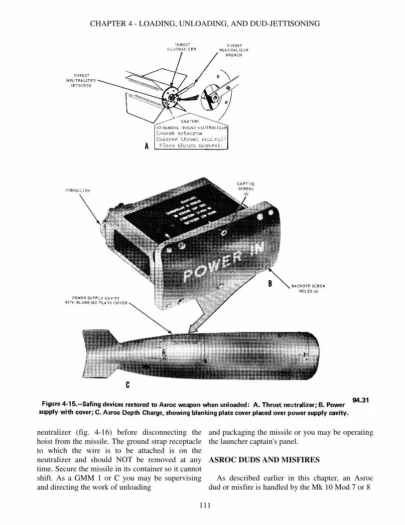
CHAPTER 4 - LOADING, UNLOADING, AND DUD-JETTISONING
neutralizer (fig. 4-16) before disconnecting the
hoist from the missile. The ground strap receptacle
to which the wire is to be attached is on the
neutralizer and should NOT be removed at any
time. Secure the missile in its container so it cannot
shift. As a GMM 1 or C you may be supervising
and directing the work of unloading
and packaging the missile or you may be operating
the launcher captain's panel.
ASROC DUDS AND MISFIRES
As described earlier in this chapter, an Asroc
dud or misfire is handled by the Mk 10 Mod 7 or 8
111

GUNNERS MATE M 1 & C
system in the same manner as a Terrier dud or
misfire. The methods of safing the torpedo and the
depth charge forms are different.
Depth Charge Mk 17
The missile configuration that carries the depth
charge payload is designated as Rocket-Thrown
Depth Charge Mk 2. If a dud or restrained firing
occurs, notify the ASW officer. He will decide
whether to return the missile to the magazine or to
package it into a container and return it to a depot
for repair. A dud is stowed, inspected and repaired
later. You will check the missile and the warhead.
The missiles in the other trays of the magazine may
be used to continue the firing exercise (or in
action). If a misfire signal shows on the launcher
captain's control panel and/or the attack console,
you must safe the depth charge at once, before it is
removed from the launcher. The nuclear weapons
officer must decide, in accordance with rules
established for these weapons, what to do with it.
After the weapon has been safed, proceed with
unloading according to the checklist, observing all
the safety precautions. If the weapon is to be off-
loaded you will need to have a missile container for
it, and two Hand Lift
Trucks Mk 41 or Mk 42. If your ship does not
carry these, you have to store the missile, order the
missile container, the hand trucks, and other
needed material, and when these arrive, unload the
missile into the container. You will need thrust
neutralizers and ISA shorting plugs, but these are
normally carried on the ship; check the supply and
order replacements if necessary. The thrust
neutralizer and shorting plug (fig. 4-15) were
removed when the missile was stowed during
replenishment. The blanking plate and power
supply seal were placed in stores at the time they
were removed when the depth charge was loaded
into the magazine. These are drawn from stores and
reused when the power supply is removed from the
depth charge.
Few ships have GMTs aboard; you need to know
how to safe the depth charge. Depth charge safing
(disarming) consists of resetting the ARM/SAFE
switch to the SAFE position and removing the
power supply (fig. 4-15B). Use the checkoff list
from SWOP W44.34.1 and follow it precisely.
Asroc Torpedo
There is no provision for jettisoning the Rocket-
Thrown Torpedo Mk 3. If, upon attempting to fire
the torpedo, the DUD light goes on, auxiliary firing
may be tried, or the missile can be returned to the
magazine to be inspected and repaired later. It
might be unloaded into a container and returned to
a depot for repair.
To remove the dud or misfire missile to a
shipping container, follow the checkoff list for
unloading.
Safing the Asroc for Unloading
Asroc torpedoes must be returned to a tender; or
deport every 6 to 12 months for maintenance
procedures, and therefore must be unloaded from
the cell. If a warshot torpedo has to be unloaded,
the position of the torpedo exploder (fig. 4-14A)
must be checked before the torpedo can be moved.
(Torpedo exploders may also be installed in
exercise heads to give an electrical "hit" signal.)
The exploder bore rod must be in the cocked
depressed position (fig. 4-14B); if it has moved
(fig. 4-14C), it must be sterilized by
112

CHAPTER 4 - LOADING, UNLOADING, AND DUD-JETTISONING
turning the sterilizing switch (fig. 4-17). To reach
the switch, break the foil seal in the top of the
exploder, then turn the itch 90 degrees in either
direction by using a screwdriver. This short circuits
the exploder power supply. (The arming device is
the part of the exploder that
contains the explosive, and must be handled with
great care. Spares are packaged and shipped
separately, not assembled in the exploder.) All
exploders must be considered armed if the bore rod
has released. If you have to offload a warshot
torpedo and the bore rod on the exploder is
113

GUNNERS MATE M 1 & C
released, sterilize the exploder before moving the
torpedo. Once the sterilizing switch has been used,
the exploder is useless for firing until a new
sterilizing switch is installed (at overhaul). The
exploder is removed from the torpedo after it is
unloaded from the launcher. Details of different
mods of the exploder vary; Exploder Mk 19 Mod
12, for example (used with Asroc), does not have a
floor switch, but has a ceiling switch and sterilizer
switch. Some mods do not have the bore rod
extension lever shown in figure 4-14C. The Mod
12 has a double-acting type of bore rod, with a bore
rod latch to lock it in the cocked position. On
dummy training missiles, inspection of the
exploder bore rod is not necessary, but operation of
the depth charge Arm/Safe switch (when the
missile is on the launcher) is required for training
purposes. Removal and replacement of the thrust
neutralizer is also practiced on dummy training
missiles. You are not likely to have a dummy
training missile on board a firing ship, but will
have exercise torpedoes.
SUMMARY
Loading, used in this chapter to mean the placing
of missiles on the launcher in preparation
for firing, is described in automatic and in step
control for .each of the types of missiles currently
used by the Navy. When everything works
perfectly, loading of missiles (with the possible
exception of Asroc) consists chiefly of pushing the
right buttons in the right sequence. However, the
GMM 1 and C must be prepared to .locate and
correct trouble in the intricate complex of the
weapon system. The chapter points out differences
between systems. Study the OP of the system you
have aboard to acquire detailed knowledge of the
mechanical, electrical, pneumatic, and hydraulic
operating components of the system. Locating the
trouble is a big step in the maintenance of a missile
launching system.
The method of disposing of missiles that fail to
fire is given with considerable detail for the
different missile systems. A missile is too big and
expensive an item to be discarded lightly; it must
be saved and repaired if possible. (Repair of the
missile is usually done at depots.)
At all times, safety rules must be remembered
and enforced. You are expected to be, ready to risk
your life in battle; but do not throwaway your life,
or that of any of your men, by neglect of safety
precautions.
114