gmp design of pharmaceutical facilities - ispe th design of pharmaceutical facilities ... •...
TRANSCRIPT
GMP Design of Pharmaceutical Facilities
Process design
Layouts and Flow Diagrams
OSD Facilities
Biopharma and Aseptic facilities
Speaker - Leonid Shnayder, Ph.D, P.E.
• Industry Professor in Pharma Manufacturing and
Engineering (PME) Program at Stevens Institute
of Technology
• Work experience:
• Pharmaceutical Process Development and Optimization
• Design of Pharma Plants (Process Engineer)
• Designed plants for Merck, Pfizer, Sanofi-Pasteur, Amgen etc.
• Teaching in the PME program at Stevens
2
Speaker - Leonid Shnayder, Ph.D, P.E.
• Courses taught:
• Intro to Pharma Manufacturing
• Validation in Pharma Manufacturing
• GMP in Pharma Facilities Design
• Manufacturing of Biopharmaceutical Products
• Manufacturing and Packaging of Oral Solid Dosage Products
• Statistical Methods in Pharma Manufacturing
3
PME Program at Stevens Institute of
Technology
• Master of Science in Pharma Manufacturing degree
• 10 courses (5 “foundation” plus 5 elective courses)
• All PME courses are offered in both on-campus and online
delivery modes. It is possible to earn the degree entirely online
• Applicants must have Bachelor’s degree in science, pharmacy
or engineering
• Graduate Certificates
• Pharmaceutical Manufacturing
• Validation, Compliance and Quality
• 4 courses each
4
Current Good Manufacturing Practices
(cGMP)
• cGMP is a set of regulations published by the US Food
and Drug Administration (FDA)
• Most national and international agencies regulating
pharma industry have similar regulations or guidelines
• cGMP regulations cover many aspects: organization
and personnel, building and facilities, equipment,
control of components, production controls,
packaging and labeling controls, laboratory controls
etc.)
• We’ll discuss aspects related to building and facilities
and equipment
5
GMP Requirements Highlights
• Building shall be of suitable size, location and construction, easily cleanable and maintainable
• Building shall be designed to prevent equipment and material mix-ups and contamination
• Separate areas shall be provided for different operations
• Provide adequate control of air pressure, microorganisms, dust, humidity and temperature as appropriate
• Written procedures required for cleaning and sanitation
6
Process design considerations
• Basic unit operations
• Process configuration
• Equipment requirements
• Process utility requirements
• Waste treatment
• Process control
• Facility requirements
• Facility layout and process flows
• Cleaning of equipment and piping
7
Process Design Tools
• Process description
• Block Flow Diagrams (BFD)
• Process Flow Diagrams (PFDs)
• Piping and Instrumentation Diagrams (P&IDs)
• Material and energy balances
• Process and utility equipment list
• Utility requirements table
• Instrument list
• Equipment specifications and/or Data Sheets
• Piping specs
8
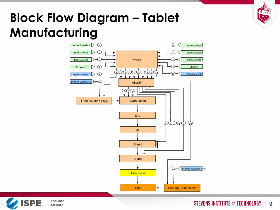
Block Flow Diagram – Tablet
Manufacturing
Mill/Sift
Coat
Mill
Coating Solution Prep
Weigh
Raw Material
Raw Material
Raw Material
Lubricant
Raw Material Raw Material 5
Excipient 4
Raw Material 3
Raw Material 2
1 Active Ingredient
10
9
6
7
8
Gran Solution Prep Granulation
Dry
10 9 8 7 6 1 2 3 4 5
9
2 3 4
Blend
Blend
8 7 6 5
Compress
Purified Water/Solvent 11
Purified Water/Solvent 11
10
9
Block Flow Diagram and its Uses
• BFD identifies major process operations and their
relationships to each other
• BFD can be useful for:
• Determining the needs for process rooms/areas
• Visualizing relationships between different rooms
• Creating a conceptual building layout or “bubble diagram”
• Identifying major process equipment needed
• BFD is used at very early project stages
• BFD can be considered as a precursor to a PFD –
Process Flow Diagram
10
Process Flow Diagrams (PFD’s)
• PFD’s are graphical representations of the manufacturing process based on manufacturing instructions
• PFD’s are reference tools that support manufacturing and assist engineers and constructors with developing facilities and equipment design requirements.
• There are no universal standards for PFD’s. Each company uses its own methodology and symbology.
• All PFD’s contain at a minimum the following basic information
• Material balance and material streams based on formulation and batch size
• Graphical representation of the major steps in the manufacturing process
• Identification of the equipment used in the manufacturing process
11
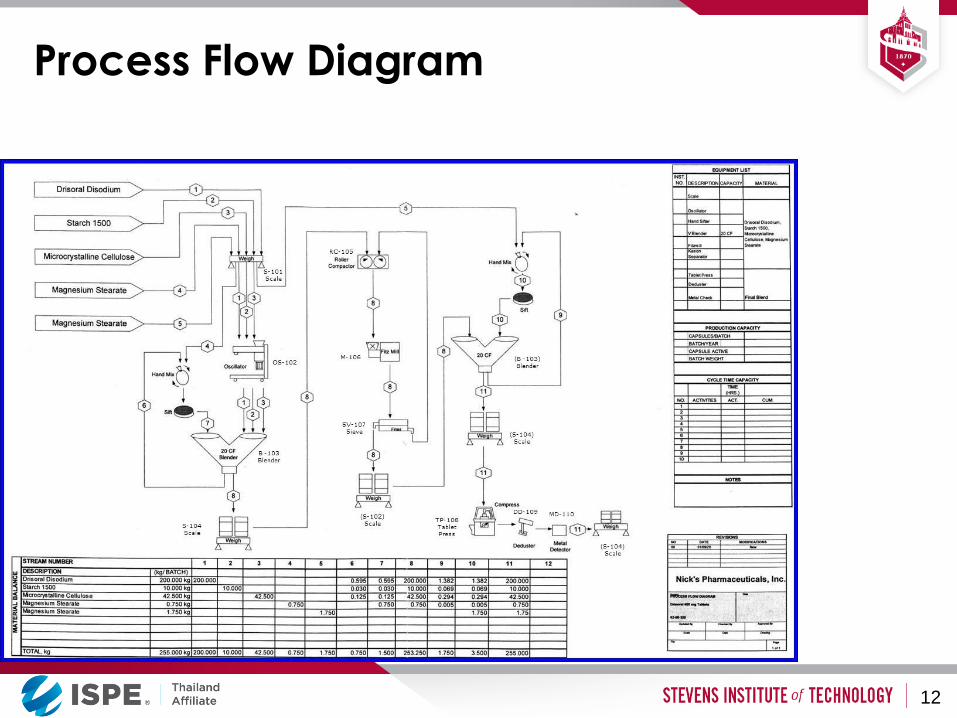
Process Flow Diagram
12

Process Flow Diagrams
• PFDs may be used to describe only the main manufacturing steps
or (better) include the support operations, such as liquid as solid waste treatment, exhaust gas treatment, generation and
distribution of purified water and other utilities
• PFD is a document generated early in a project – usually during
“conceptual design” stage, and may be updated to reflect
changes incorporated at later stages
• PFDs may be used for developing preliminary equipment list and
sizing of the major equipment
• PFDs help architects to allocate appropriate spaces for all process
operations and develop logical plant layout
• PFDs are also used as a basis for more detailed process drawings called P&IDs – Piping and Instrumentation Diagrams
13
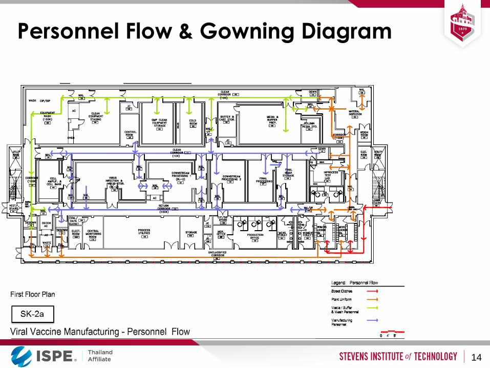
Personnel Flow & Gowning Diagram
14
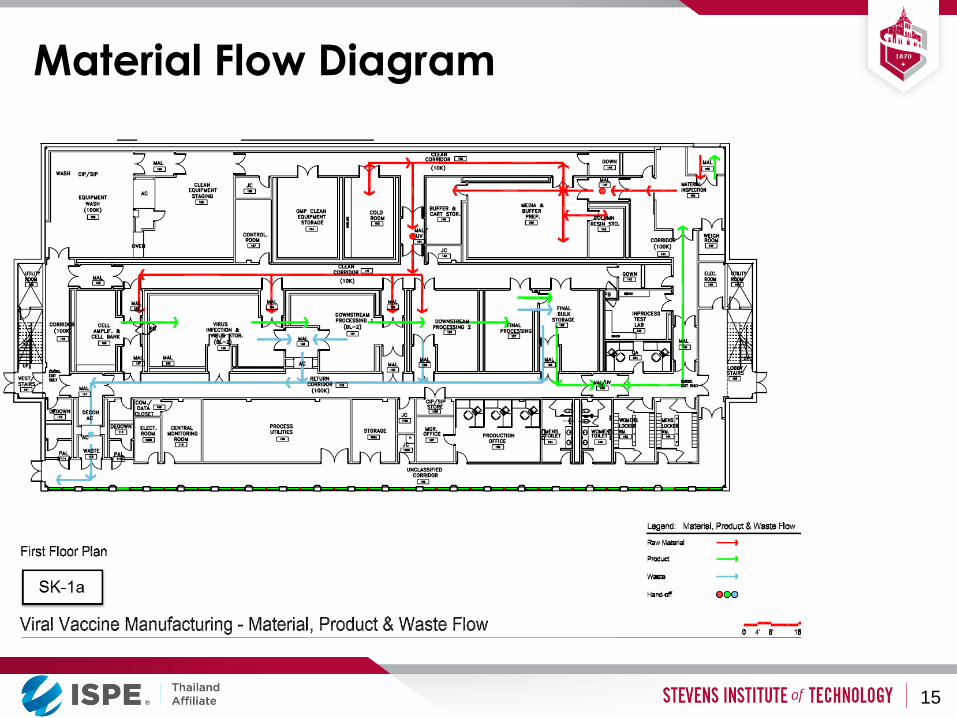
Material Flow Diagram
15
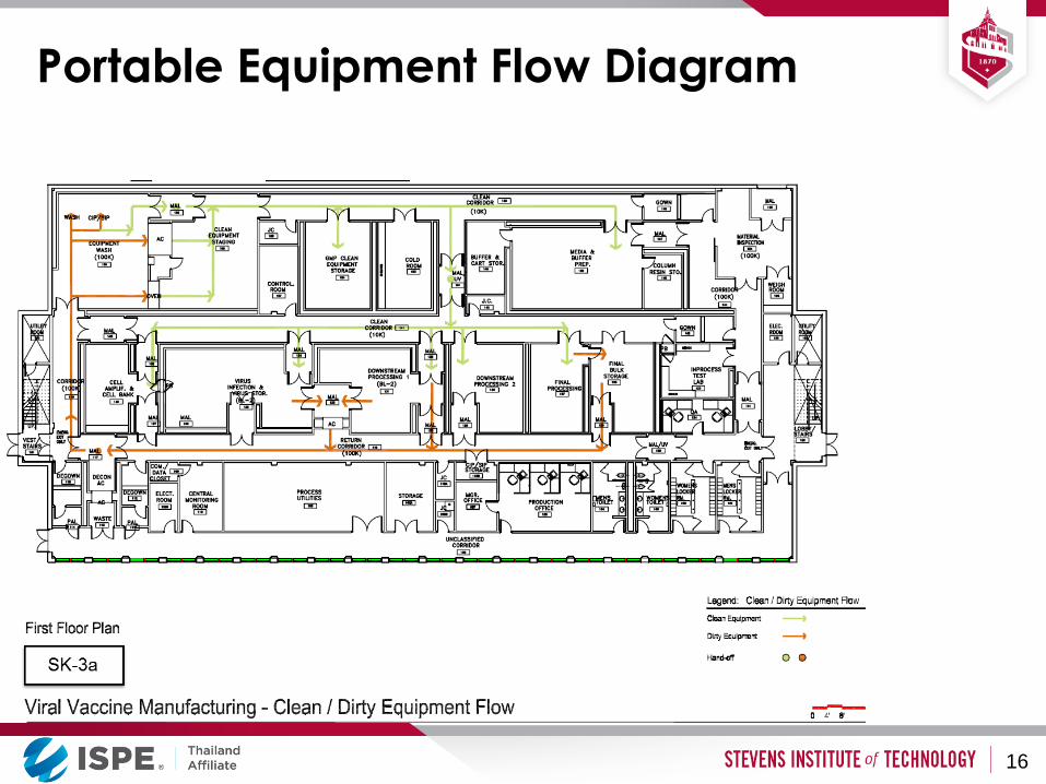
Portable Equipment Flow Diagram
16
Process and Facility Design - Summary
• Facility design and layout must satisfy:
• Process requirements
• Personnel flows
• Material flows (raw materials and products)
• Equipment layout requirements
• Operational access requirements
• Maintenance access requirements
• Facility should be designed around process needs!
17
Building Materials
Clean Room Features
• Walls and floors designed for easy cleaning, resistant to wear and cleaning chemicals
• Coved floor and wall corners
• Minimize horizontal piping, ducts, equipment surfaces where dust can accumulate
• Lighting is supplied by sealed fixtures, often incorporated into ceiling HEPA filter modules.
19
Clean Room Features (cont’d)
• Typical clean room finishes include:
• Epoxy terrazzo floors
• Epoxy painted walls
• Suspended drywall or plaster ceiling, painted for easy cleaning
• Clean rooms can be built at the site or purchased as
modules from a vendor
20
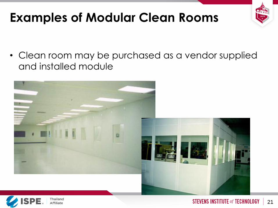
Examples of Modular Clean Rooms
• Clean room may be purchased as a vendor supplied
and installed module
21

Building Materials and Finishes -
Summary
• Materials and Finishes are selected for suitability within every select environment in the facility.
• A very informed basis of understanding is required to properly select materials and finishes. Knowledge of the manufacturing process(s), SOP’s, staff activities and maintenance needs for all areas within the facility are vital to a successful solution.
22
Manufacturing of Solid Dosage
Products
Guiding Principles for Facility Design
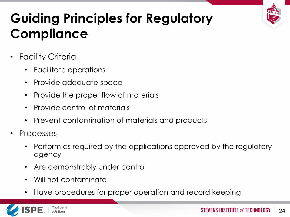
Guiding Principles for Regulatory
Compliance
• Facility Criteria
• Facilitate operations
• Provide adequate space
• Provide the proper flow of materials
• Provide control of materials
• Prevent contamination of materials and products
• Processes
• Perform as required by the applications approved by the regulatory agency
• Are demonstrably under control
• Will not contaminate
• Have procedures for proper operation and record keeping
24
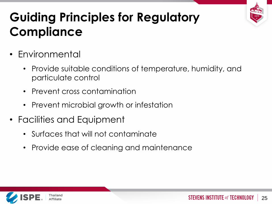
Guiding Principles for Regulatory
Compliance
• Environmental
• Provide suitable conditions of temperature, humidity, and
particulate control
• Prevent cross contamination
• Prevent microbial growth or infestation
• Facilities and Equipment
• Surfaces that will not contaminate
• Provide ease of cleaning and maintenance
25

Contamination and Level of Protection
Criteria
• Potential Contamination Sources
• HVAC Systems
• Process equipment cleanliness
• Room construction issues
• Containerization and transport of materials
• Personnel
• Infiltration from other areas
26
Unit Operations in Solid
Dosage Manufacturing
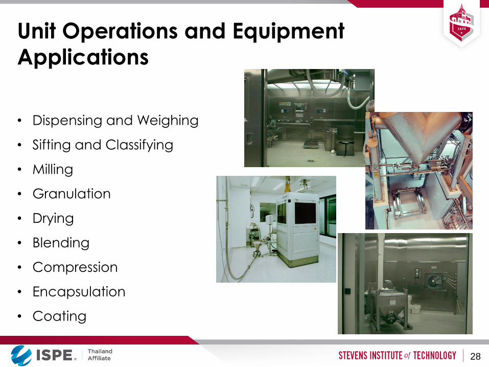
Unit Operations and Equipment
Applications
• Dispensing and Weighing
• Sifting and Classifying
• Milling
• Granulation
• Drying
• Blending
• Compression
• Encapsulation
• Coating
28

Dispensing
• Small Volume Dispensing
• Down Flow Laminar Flow Hoods
• Dedicated Rooms with Environmental Controls
• Large Volume Dispensing
• Silos
• Super Sacks
• Pneumatic Conveyance and Weigh Systems
• Gravity Transfer and Weigh Systems
29
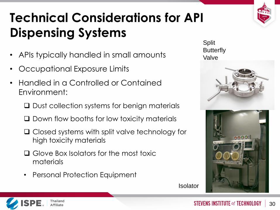
Technical Considerations for API
Dispensing Systems
• APIs typically handled in small amounts
• Occupational Exposure Limits
• Handled in a Controlled or Contained
Environment:
Dust collection systems for benign materials
Down flow booths for low toxicity materials
Closed systems with split valve technology for
high toxicity materials
Glove Box Isolators for the most toxic
materials
• Personal Protection Equipment
Split
Butterfly
Valve
Isolator
30
Other Design Considerations
• Storage and handling of materials in bulk containers
(IBC), drums, bags, etc
• Partials inventory (Unused material in drums to be returned to
inventory)
• Material Handling Equipment
• Staging and Put Down Areas
• Wash Areas and Equipment Storage
• Pallet washers
• IBC washers
31
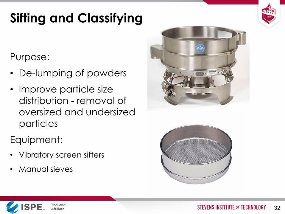
Sifting and Classifying
Purpose:
• De-lumping of powders
• Improve particle size
distribution - removal of
oversized and undersized
particles
Equipment:
• Vibratory screen sifters
• Manual sieves
32

Milling
• Used for:
• Particle size reduction
• Change particle shape
• De-lumping
33
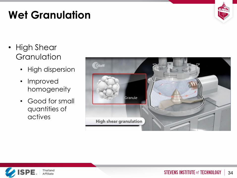
Wet Granulation
• High Shear
Granulation
• High dispersion
• Improved
homogeneity
• Good for small
quantities of
actives
34
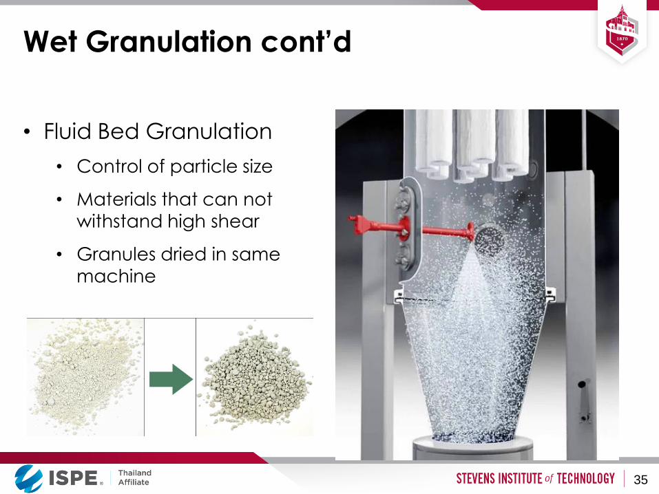
Wet Granulation cont’d
• Fluid Bed Granulation
• Control of particle size
• Materials that can not
withstand high shear
• Granules dried in same
machine
35
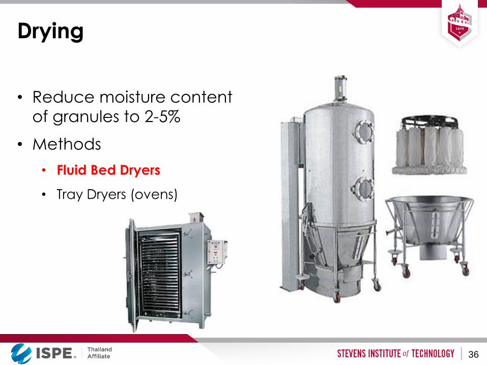
Drying
• Reduce moisture content
of granules to 2-5%
• Methods
• Fluid Bed Dryers
• Tray Dryers (ovens)
36
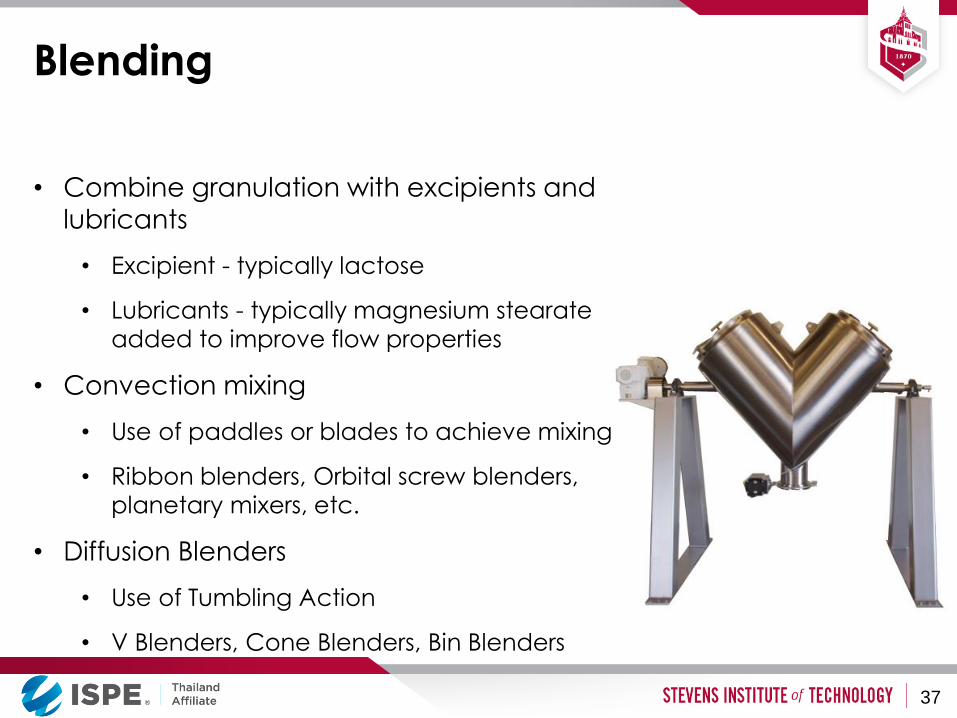
Blending
• Combine granulation with excipients and
lubricants
• Excipient - typically lactose
• Lubricants - typically magnesium stearate
added to improve flow properties
• Convection mixing
• Use of paddles or blades to achieve mixing
• Ribbon blenders, Orbital screw blenders,
planetary mixers, etc.
• Diffusion Blenders
• Use of Tumbling Action
• V Blenders, Cone Blenders, Bin Blenders
37
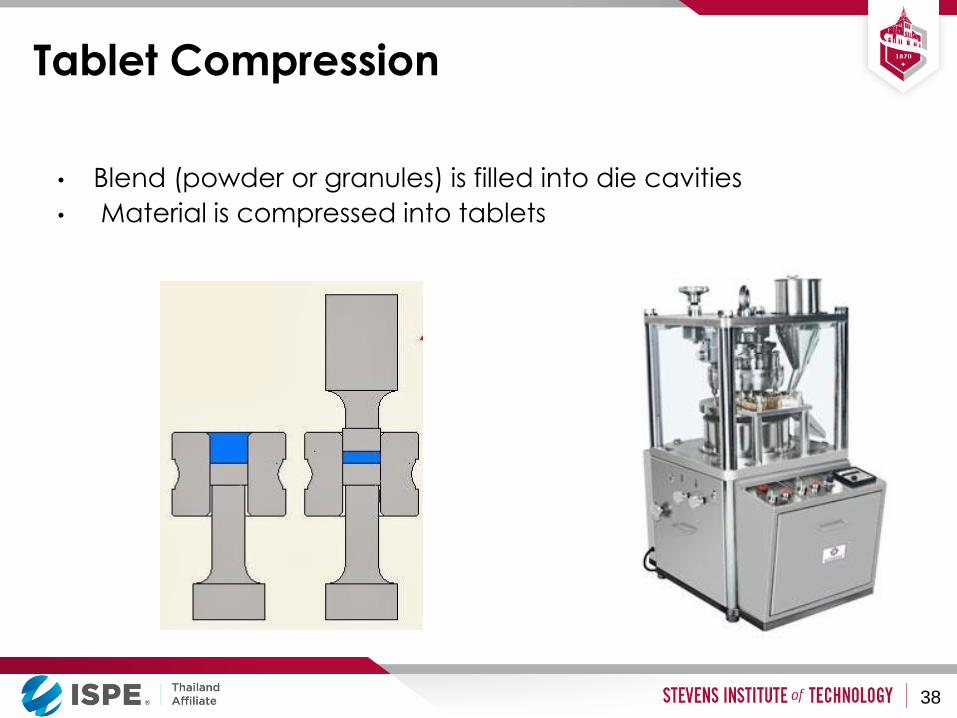
Tablet Compression
• Blend (powder or granules) is filled into die cavities
• Material is compressed into tablets
38
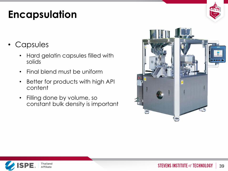
Encapsulation
• Capsules
• Hard gelatin capsules filled with solids
• Final blend must be uniform
• Better for products with high API content
• Filling done by volume, so constant bulk density is important
39
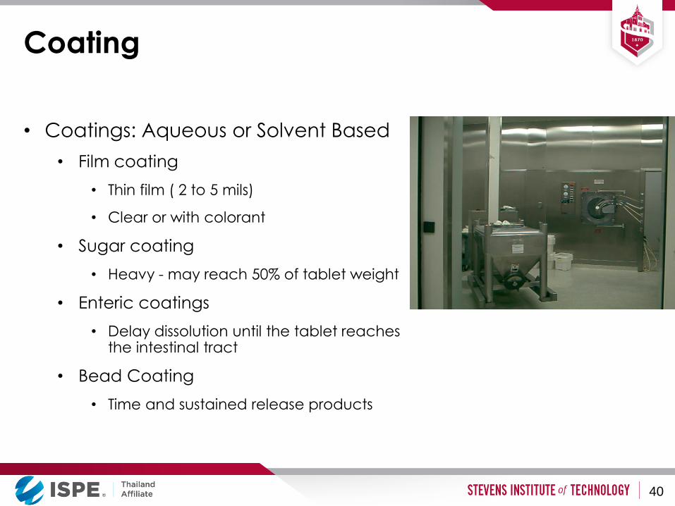
Coating
• Coatings: Aqueous or Solvent Based
• Film coating
• Thin film ( 2 to 5 mils)
• Clear or with colorant
• Sugar coating
• Heavy - may reach 50% of tablet weight
• Enteric coatings
• Delay dissolution until the tablet reaches the intestinal tract
• Bead Coating
• Time and sustained release products
40
Coating
• Process entails application of protective coatings to tablets
• Coatings are applied in solution. May be water or solvent based
• Multiple cycles of solution application and drying may be needed.
• Multiple layers of coatings are applied to obtain the desired result
• Equipment Used in the Process
• Open Coating Pans (Conventional Pans)
• Perforated Coating Pans: Batch or Continuous Process
• Wurster Columns (Fluid Bed Processors) – used for coating beads or granules
41
Facility Layout
• Facility layout must:
• Provide short and logical routes for material and
personnel flow
• Avoid cross-flows whenever possible
• Provide means of separation for quarantined,
released and rejected materials
• Provide sufficient space for each operation,
including staging, washing and other ancillary
areas
• Help prevent cross-contamination
42
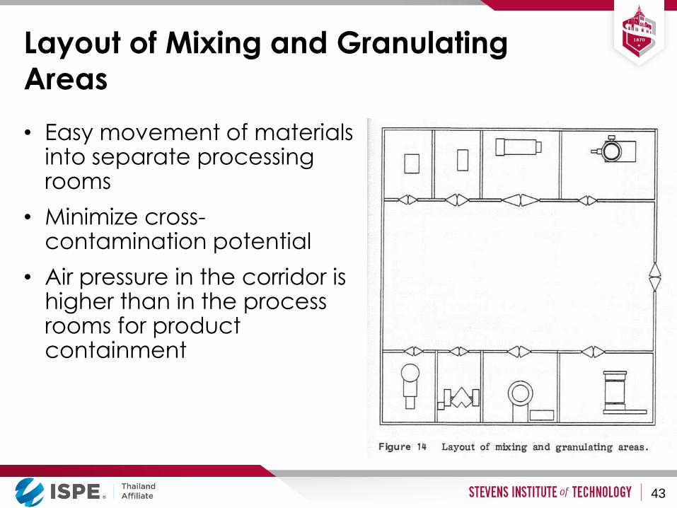
Layout of Mixing and Granulating
Areas
• Easy movement of materials into separate processing rooms
• Minimize cross-contamination potential
• Air pressure in the corridor is higher than in the process rooms for product containment
43
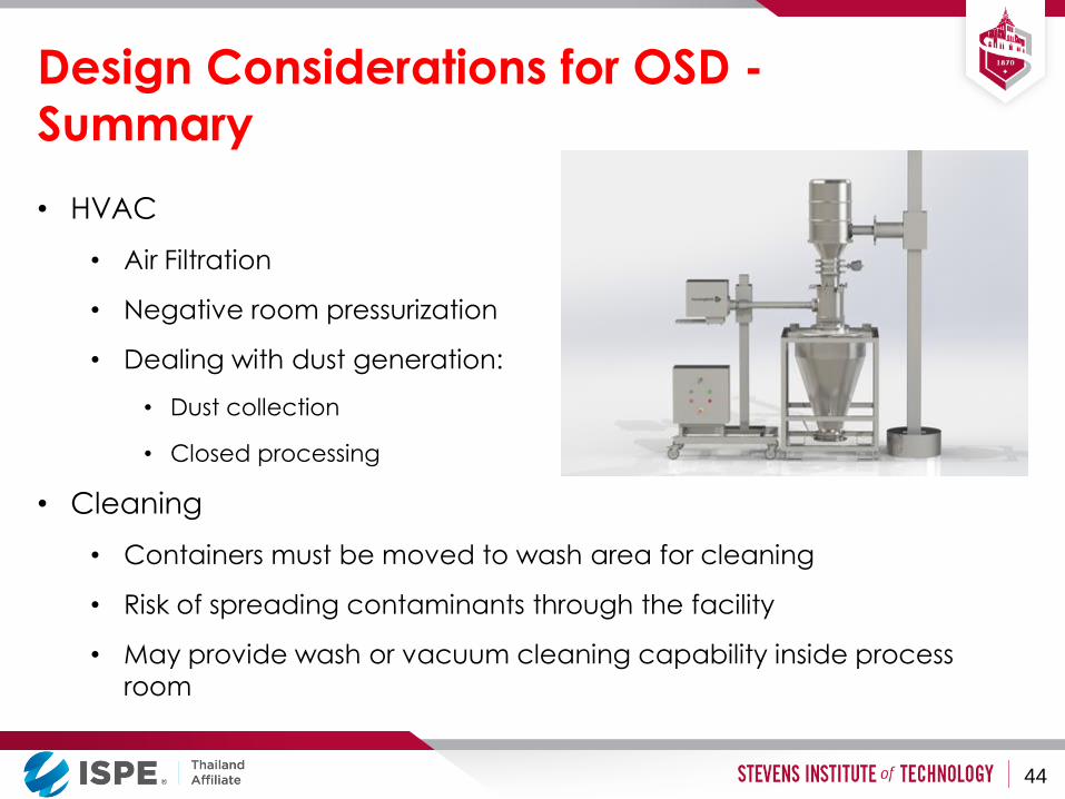
Design Considerations for OSD -
Summary
• HVAC
• Air Filtration
• Negative room pressurization
• Dealing with dust generation:
• Dust collection
• Closed processing
• Cleaning
• Containers must be moved to wash area for cleaning
• Risk of spreading contaminants through the facility
• May provide wash or vacuum cleaning capability inside process
room
44

BioPharmaceutical Manufacturing Facilities
Biopharmaceutical Processes and Facilities
Room classification
What is Biopharmaceutical
Technology?
• Processes using microorganisms or animal cells for
synthesis of products
• Isolation and purification technology for biologically
derived compounds
• Modern biotechnology uses genetically engineered
cells or microbes
• Products include drugs, vaccines and other high value
compounds
• Many biotech drugs are proteins
46
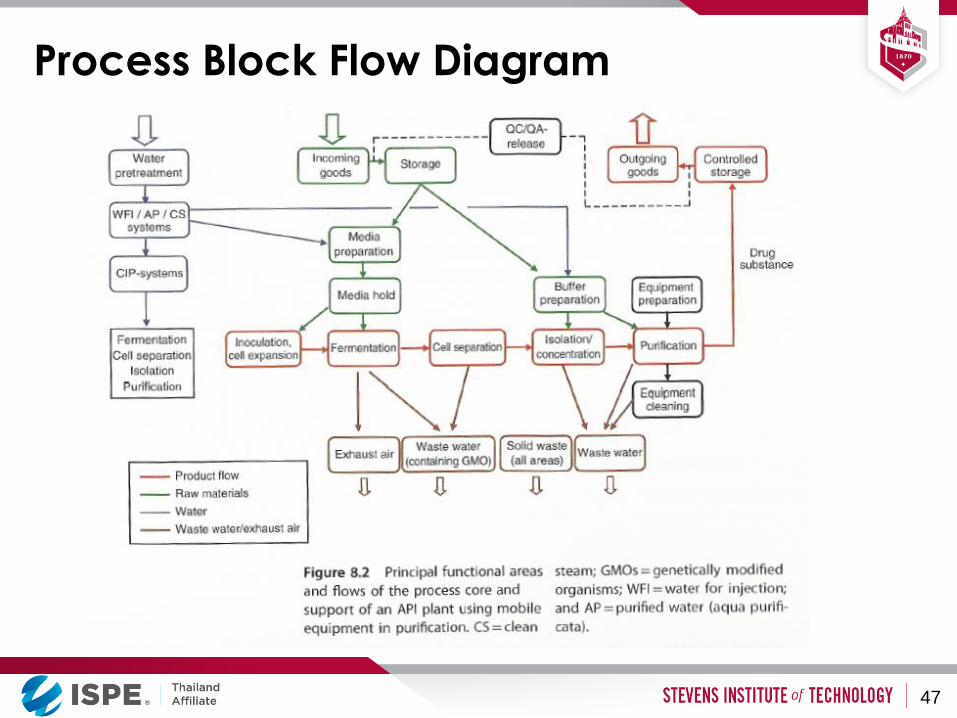
Process Block Flow Diagram
47
Building Design Considerations
• Operational Efficiency
• Operational Safety
• Protection of Product from contamination
• Protection of Personnel
• Protection of Facility
• Maintainability
48
Program Design Considerations
• Equipment Arrangements
• Material Flow
• Personnel Flow
• Product Flow
• Waste Flow
• Adjacencies
• Segregation
• Flexibility
• Expandability
49

Single Product Facility with Minimal
Segregation
50
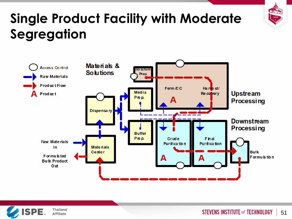
Single Product Facility with Moderate
Segregation
51

Multi-Product Facility with Moderate
Segregation
52
Layout Considerations - Summary
• Adjacency of related spaces
• Logical and simple flow of personnel, portable equipment and materials
• Avoid where possible “clean” and “dirty” equipment and personnel passing through the same corridors, gowning areas etc.
• “Air locks” are used at major separation points where maintaining pressure differential is important
• Cleaner spaces usually are located in the middle of a facility, and surrounded by areas of lower classification
53
Classification of Clean Rooms
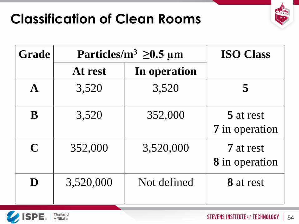
Grade Particles/m3 ≥0.5 µm ISO Class
At rest In operation
A 3,520 3,520 5
B 3,520 352,000 5 at rest
7 in operation
C 352,000 3,520,000 7 at rest
8 in operation
D 3,520,000
Not defined 8 at rest
54
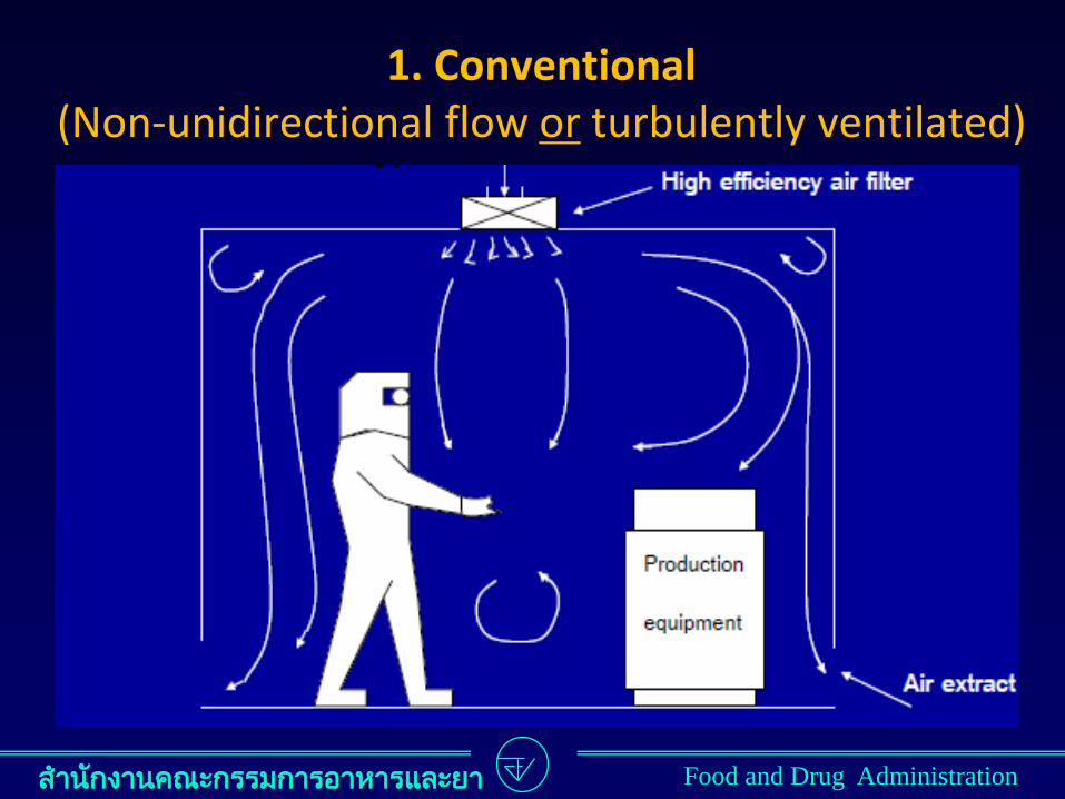
HVAC Techniques
• Air filtration, including “High Efficiency Particulate Air” filters (HEPA filters)
• Directional flow or air
• Pressure relationships within and between adjacent spaces
• Humidification (used mostly in winter in cold climates), dehumidification (mostly in summer)
• Heating and cooling to maintain constant temperature
55
Air Filtration
• The low particulate counts in classified rooms are achieved by continuous recirculation of room air with HEPA filters in the recirculation loop
• The cleaner the room needs to be, the higher recirculation rate required
• The degree of recirculation is commonly expressed as number of room air changes per hour (air flow rate divided by the room volume)
56
Air Filtration
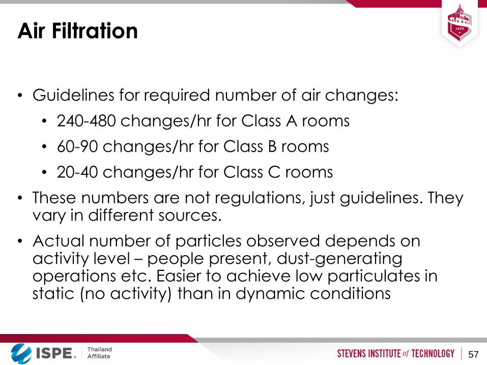
• Guidelines for required number of air changes:
• 240-480 changes/hr for Class A rooms
• 60-90 changes/hr for Class B rooms
• 20-40 changes/hr for Class C rooms
• These numbers are not regulations, just guidelines. They vary in different sources.
• Actual number of particles observed depends on activity level – people present, dust-generating operations etc. Easier to achieve low particulates in static (no activity) than in dynamic conditions
57
Air Pressurization
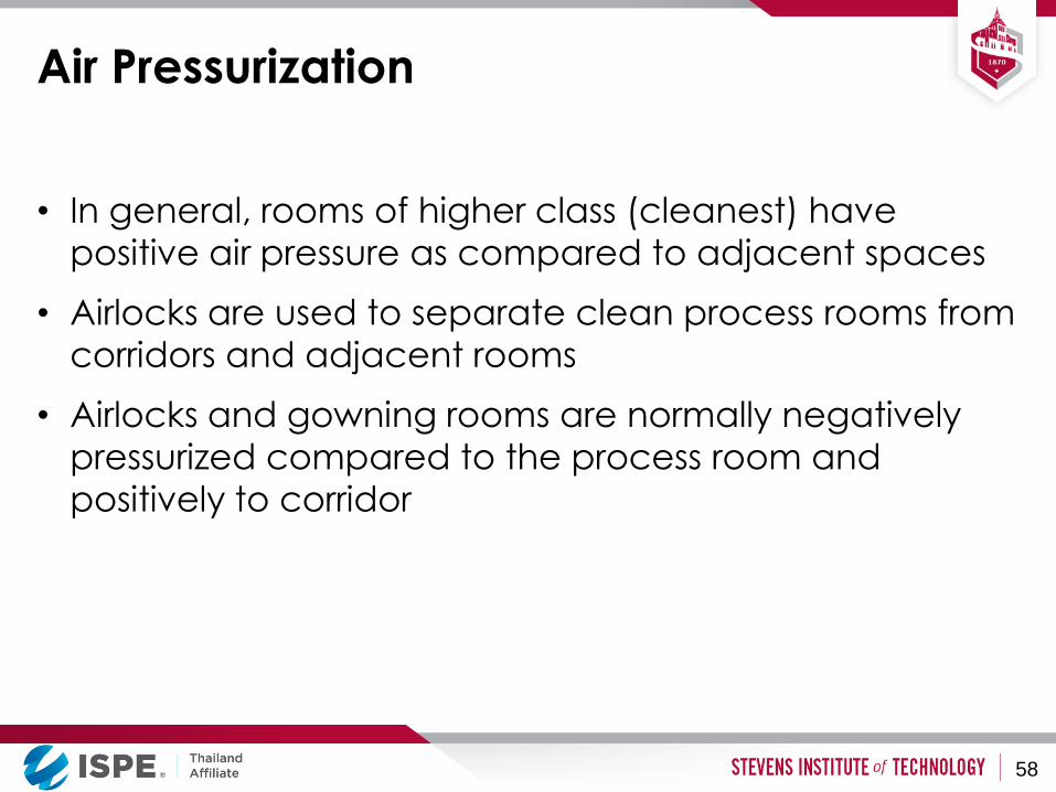
• In general, rooms of higher class (cleanest) have
positive air pressure as compared to adjacent spaces
• Airlocks are used to separate clean process rooms from
corridors and adjacent rooms
• Airlocks and gowning rooms are normally negatively
pressurized compared to the process room and
positively to corridor
58
Air Pressurization
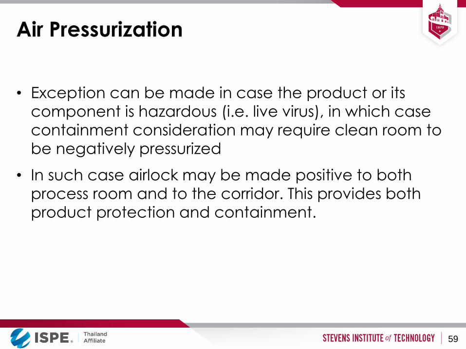
• Exception can be made in case the product or its
component is hazardous (i.e. live virus), in which case
containment consideration may require clean room to
be negatively pressurized
• In such case airlock may be made positive to both
process room and to the corridor. This provides both
product protection and containment.
59

Air Pressurization
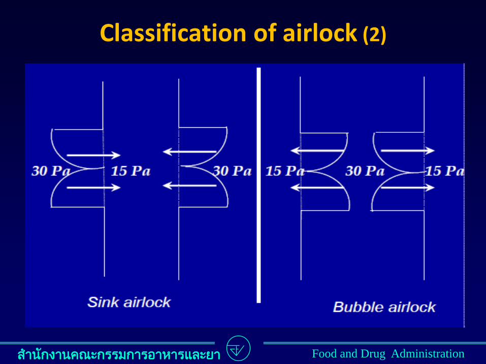
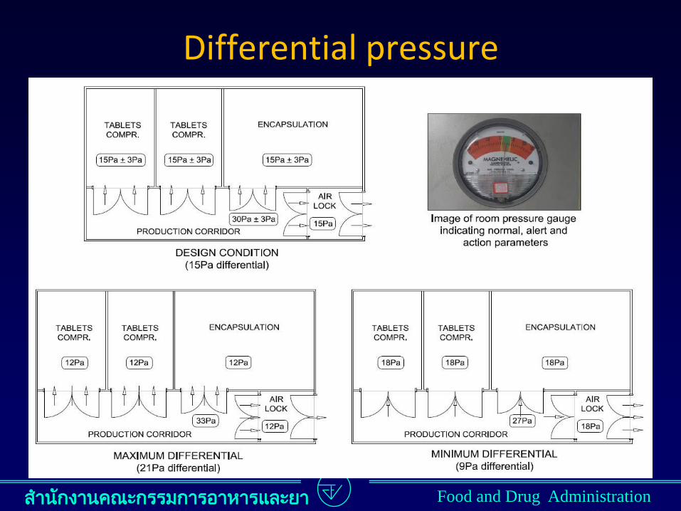
• Recommended pressure differential between adjacent areas is 10 – 15 Pa, as measured with doors closed
• When a door opens, pressure differential essentially goes to zero. That is why air locks are installed at critical connection points, and the two doors in an air lock are never opened simultaneously (often enforced by interlocking controls on electrically operated doors)
• Rooms need to be sealed as tight as possible to enable maintaining required pressure differential
60
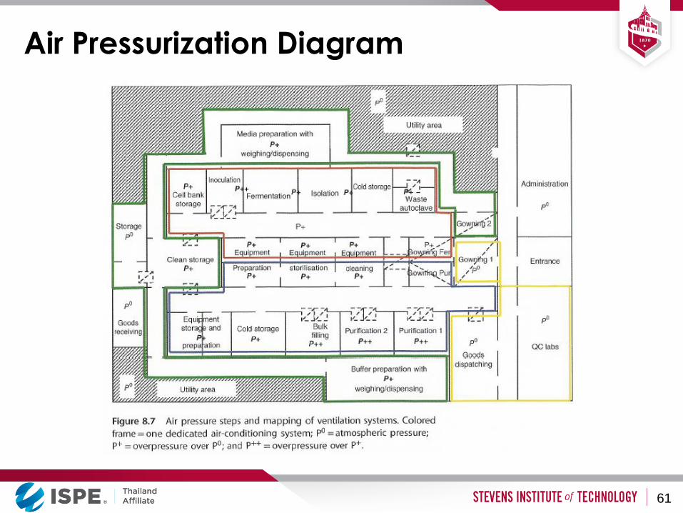
Air Pressurization Diagram
61
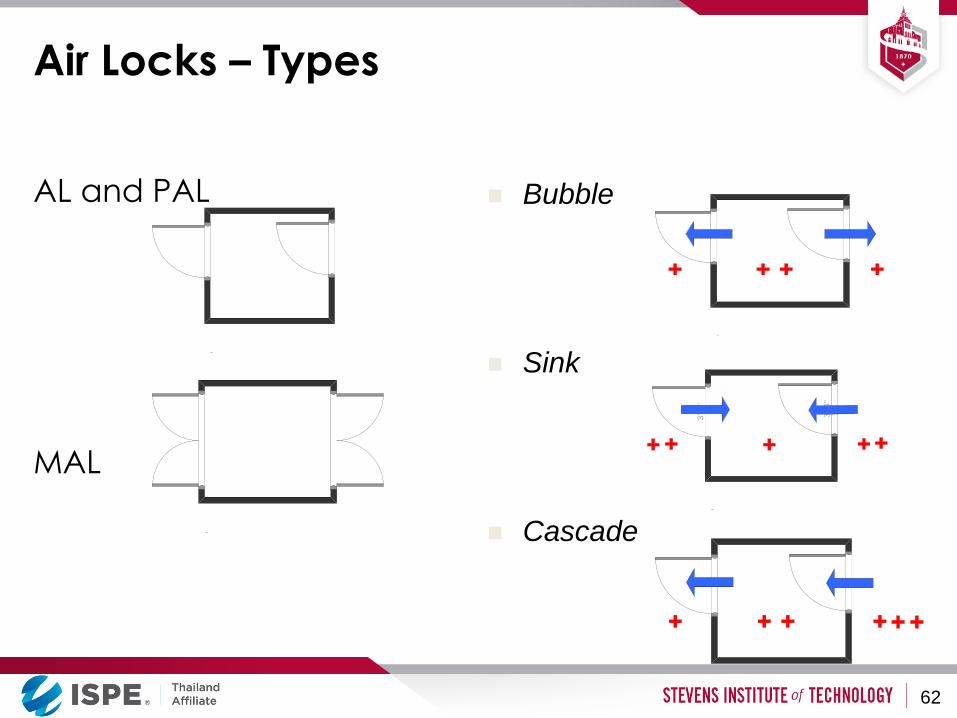
AL and PAL
MAL
Air Locks – Types
Bubble
Sink
Cascade
3 ' -
0 "
3 ' -
0 "
62
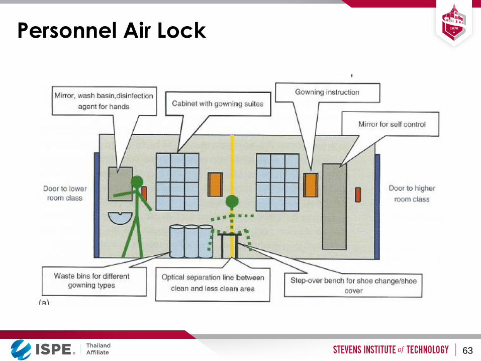
Personnel Air Lock
63
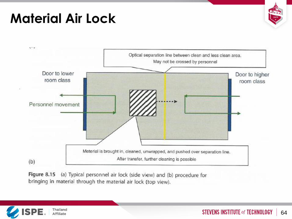
Material Air Lock
64
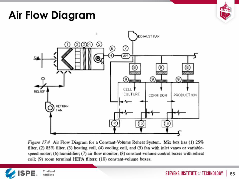
Air Flow Diagram
65

Air Quality Monitoring
• Number of particles per unit of air volume is tested during facility qualification and routinely. Such testing is done both “at rest” (no activity) and during normal operations. Portable (shown in the picture) or permanently installed particle counters may be used.
Source - www.metone.com
66
HVAC - Summary
• Clean room classes A, B, C (and sometimes D) are
commonly used in biopharma facilities
• To maintain air cleanliness we use:
• Air recirculation at high flow rates with HEPA filters in the recirculation loop
• Air pressure differentials between adjacent spaces
• Air locks for personnel and materials
• Personnel gowning and access control
• Air quality monitoring (periodic or continuous)
67
Single- and Multi-product Plants
• If we have a product with high sales volume, single-
product plant is better
• If we have multiple products with similar technologies
and smaller volumes, multi-product plant may be
better
• In multi-product plants:
• Flexibility must be built into the floor plan
• Avoidance of cross-contamination is critical
• May operate by campaigns or by parallel processing
68
Equipment and Piping Design
Concepts
• Most large plants have fixed stainless steel equipment
and fixed process piping
• Flexibility can be achieved by using flexible piping
(hoses) in addition to the fixed piping
• Many smaller plants use disposable equipment –
storage bags, fermentation bags, , filters etc.
69
Plant Design Concepts - Summary
• Three principle variables that are in competition with
each other:
• Investments (capital cost)
• Operating costs
• Flexibility
• Different designs may be used for different situations:
• Multi product versus single product facilities
• Stainless steel versus disposable (single use) equipment
70
Aseptic Processing Facilities
Introduction
• Aseptic processing - all the individual components
(product, vials & stoppers) are sterilized individually
and assembled in a very high quality environment
• Only a small fraction of the final product is tested to
confirm its sterility and therapeutic value
• Manufacturer has no direct data other than the
design of their process to confirm that the product is
safe for human use
72
Containers for Aseptic Products
Examples:
– Vial (sealed using a rubber stopper and aluminum
seal)
– Ampoule (a glass container sealed using heat
directly after filling)
– Syringe (sealed with a rubber stopper and a needle
cover)
– Plastic bottle (sealed with a plastic cap)
– Blow-Fill-Sealed Bottles (a plastic bottle that is made
filled and sealed in one step)
73
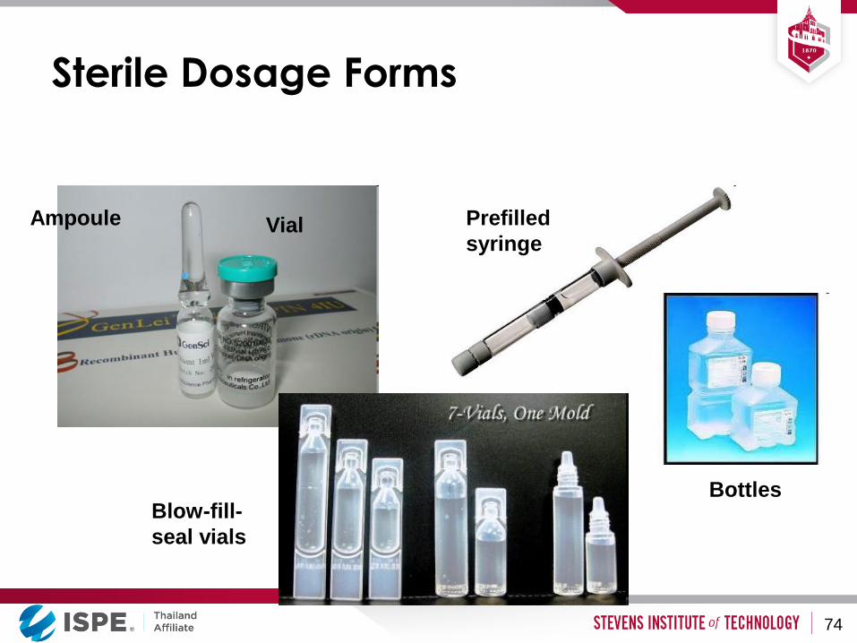
Sterile Dosage Forms
Ampoule Vial Prefilled
syringe
Blow-fill-
seal vials
Bottles
74
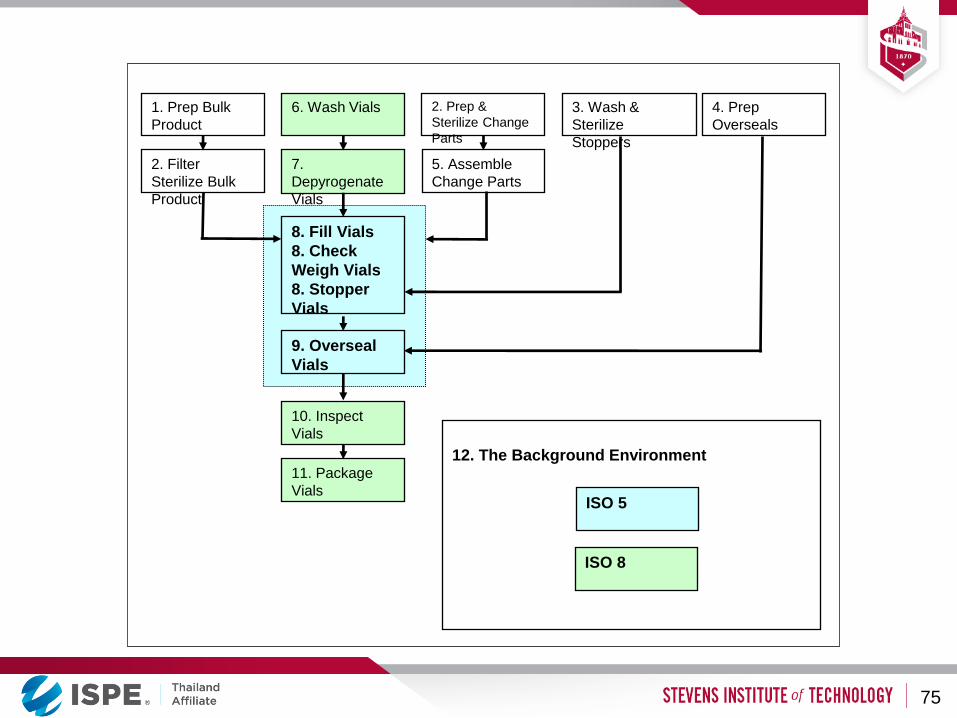
12. The Background Environment
6. Wash Vials
7.
Depyrogenate
Vials
8. Fill Vials
8. Check
Weigh Vials
8. Stopper
Vials
1. Prep Bulk
Product
3. Wash &
Sterilize
Stoppers
2. Prep &
Sterilize Change
Parts
10. Inspect
Vials
9. Overseal
Vials
2. Filter
Sterilize Bulk
Product
11. Package
Vials
4. Prep
Overseals
5. Assemble
Change Parts
ISO 5
ISO 8
75
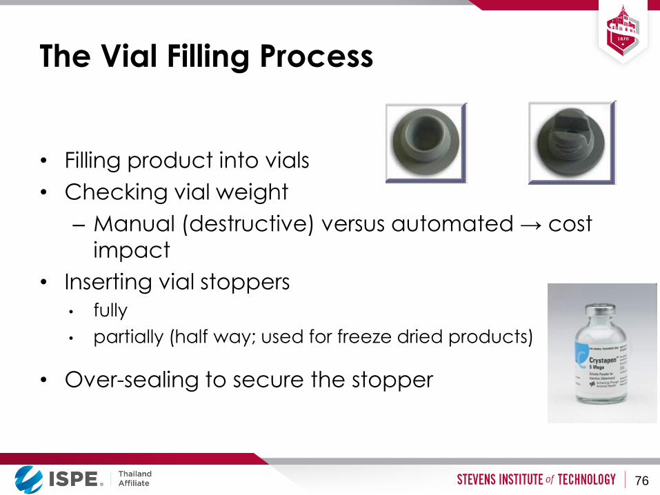
• Filling product into vials
• Checking vial weight
– Manual (destructive) versus automated → cost
impact
• Inserting vial stoppers
• fully
• partially (half way; used for freeze dried products)
• Over-sealing to secure the stopper
The Vial Filling Process
76
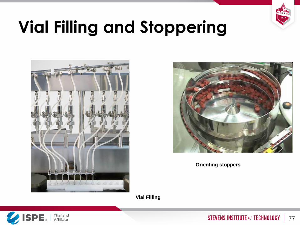
Vial Filling and Stoppering
77
Orienting stoppers
Vial Filling
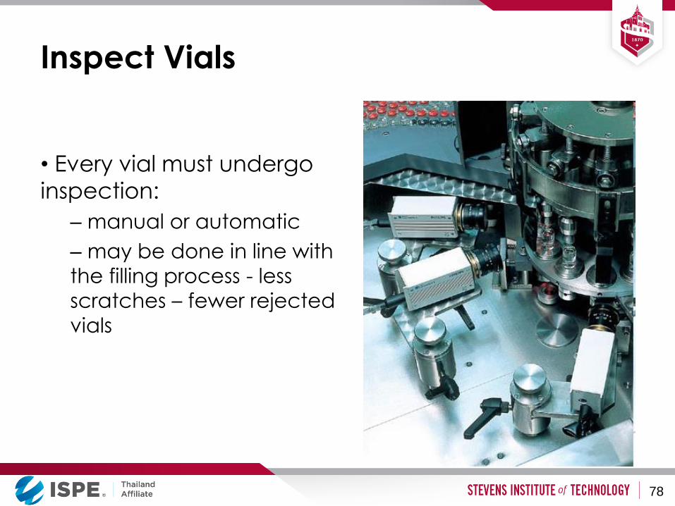
Inspect Vials
• Every vial must undergo
inspection:
– manual or automatic
– may be done in line with
the filling process - less
scratches – fewer rejected
vials
78

The Vial Filling Process
• The aseptic processing steps (where the
product and product contact parts are
exposed) are performed in a Class A / ISO5
environment
• The other classes are used for areas with
other activities depending on the potential
impact of on the process
79
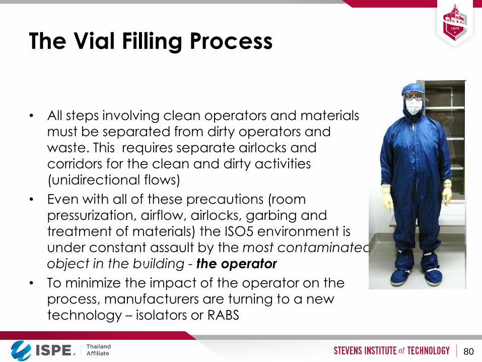
The Vial Filling Process
• All steps involving clean operators and materials
must be separated from dirty operators and
waste. This requires separate airlocks and
corridors for the clean and dirty activities (unidirectional flows)
• Even with all of these precautions (room
pressurization, airflow, airlocks, garbing and
treatment of materials) the ISO5 environment is under constant assault by the most contaminated
object in the building - the operator
• To minimize the impact of the operator on the
process, manufacturers are turning to a new technology – isolators or RABS
80
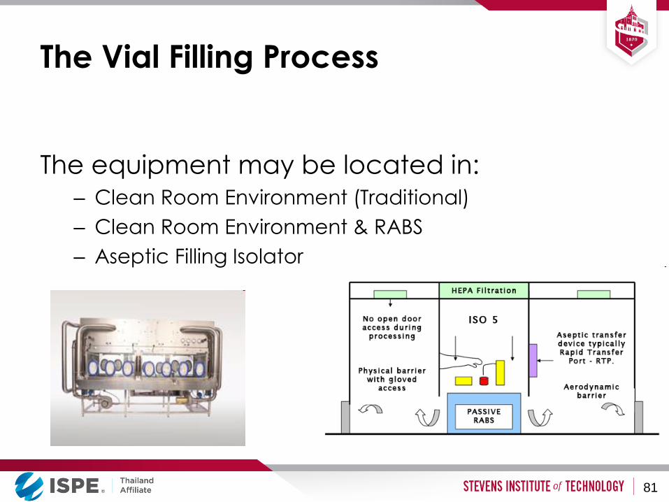
The Vial Filling Process
The equipment may be located in: – Clean Room Environment (Traditional)
– Clean Room Environment & RABS
– Aseptic Filling Isolator
81
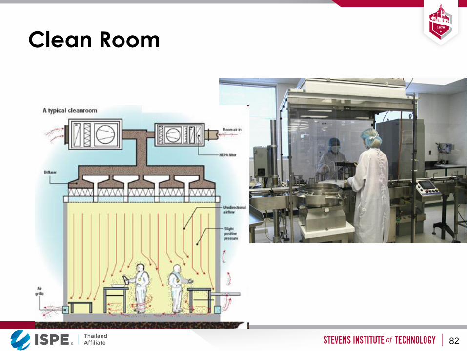
Clean Room
82
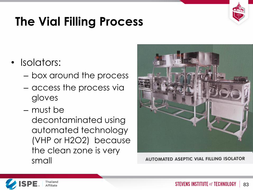
The Vial Filling Process
• Isolators:
– box around the process
– access the process via
gloves
– must be
decontaminated using
automated technology
(VHP or H2O2) because
the clean zone is very
small
83
The Vial Filling Process
• Advantages of isolators:
– The operator is removed from the process, so less product
risk
– Can be located in an ISO8 environment
• Reduced ISO5 area
• Reduced requirements for the sterile garb
• Fewer airlocks and material sanitization steps
– Material and people movement in the facility is simplified
– Cleaning and cleaning validation reduced
– Lower long term operation cost than traditional clean room facility
84
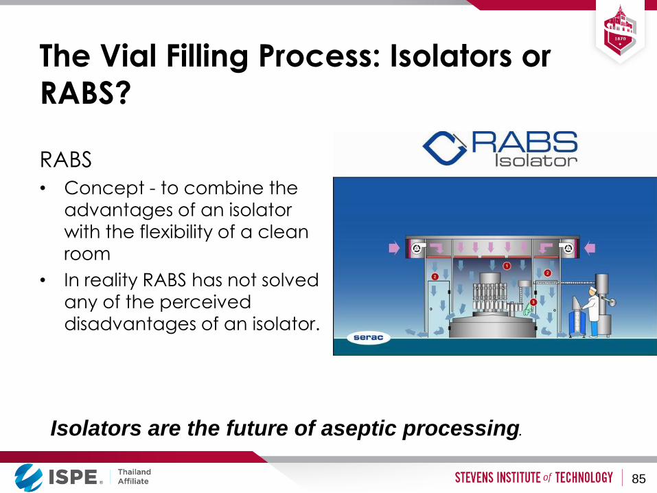
The Vial Filling Process: Isolators or
RABS?
RABS
• Concept - to combine the
advantages of an isolator
with the flexibility of a clean room
• In reality RABS has not solved
any of the perceived
disadvantages of an isolator.
Isolators are the future of aseptic processing.
85
Factors affecting Aseptic Filling -
Summary
• Success of an aseptic process depends on:
– Equipment design
– Process design and controls
– Facility and Room design
– HVAC design
– Clean Rooms/Isolators/RABS
– Operators: gowning, training, procedures
– Clean Utilities
86

References
1. cGMP Regulations: https://www.accessdata.fda.gov/scripts/cdrh/cfdocs/cfCFR/CFRSearch.cfm?CFRPart=211
2. ISPE Biopharmaceutical Manufacturing Facilities Baseline Guide – www.ispe.org
3. International Standard ISO14644-1”Cleanrooms and associated controlled environments” — Part 1: Classification of air cleanliness. 2015.
87
Questions?
88
ส ำนกงำนคณะกรรมกำรอำหำรและยำ Food and Drug Administration
Regulatory requirement for Pharmaceutical facilities
โดย ภญ.พชรวรรณ ฝงนล
กลมก ำกบดแลหลงออกสตลำด ส ำนกยำ
ส ำนกงำนคณะกรรมกำรอำหำรและยำ
16 กมภำพนธ 2560
ส ำนกงำนคณะกรรมกำรอำหำรและยำ Food and Drug Administration
• ปจจยทตองค ำนงถงในกำรออกแบบสถำนทผลตยำ
• กฎหมำยทเกยวของ
• Protection aspects
• นยำมศพทส ำคญ
• เทคนคหลกเลยงกำรปนเปอนขำม
• Shell-like containment control concept
• Classification of airlock
• Differential pressure
หวขอกำรบรรยำย (1)
ส ำนกงำนคณะกรรมกำรอำหำรและยำ Food and Drug Administration
หวขอกำรบรรยำย (2)
• Type of “Clean area”
• Cleanroom condition
• กำรแบงประเภทหองสะอำด (EN/ISO 14644-1)
• ขดจ ำกดส ำหรบกำรตรวจตดตำมจลนทรยของบรเวณสะอำด
ระหวำงปฏบตงำน
• กำรปฏบตงำนในแตละระดบควำมสะอำด
• ตวอยำงแบบแปลนสถำนทผลตยำแตละประเภท
ส ำนกงำนคณะกรรมกำรอำหำรและยำ Food and Drug Administration
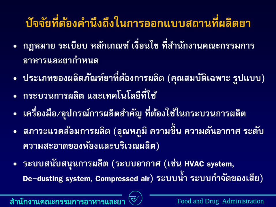
ปจจยทตองค ำนงถงในกำรออกแบบสถำนทผลตยำ • กฎหมำย ระเบยบ หลกเกณฑ เงอนไข ทส ำนกงำนคณะกรรมกำร
อำหำรและยำก ำหนด
• ประเภทของผลตภณฑยำทตองกำรผลต (คณสมบตเฉพำะ รปแบบ)
• กระบวนกำรผลต และเทคโนโลยทใช
• เครองมอ/อปกรณกำรผลตส ำคญ ทตองใชในกระบวนกำรผลต
• สภำวะแวดลอมกำรผลต (อณหภม ควำมชน ควำมดนอำกำศ ระดบ
ควำมสะอำดของหองและบรเวณผลต)
• ระบบสนบสนนกำรผลต (ระบบอำกำศ (เชน HVAC system,
De-dusting system, Compressed air) ระบบน ำ ระบบก ำจดของเสย)

ส ำนกงำนคณะกรรมกำรอำหำรและยำ Food and Drug Administration
กฎหมำยทเกยวของ (1)
ประกำศกระทรวงสำธำรณสข เรอง กำรก ำหนดรำยละเอยด
เกยวกบหลกเกณฑและวธกำรในกำรผลตยำแผนปจจบนและ
แกไขเพมเตมหลกเกณฑและวธกำรในกำรผลตยำแผนโบรำณ
ตำมกฎหมำยวำดวยยำ พ.ศ. 2559
- รฐมนตรวาการกระทรวงสาธารณสข ลงนาม 18 พฤษภาคม 2559
- ประกาศในราชกจจานเบกษา วนท 14 กนยายน 2559
ส ำนกงำนคณะกรรมกำรอำหำรและยำ Food and Drug Administration
กฎหมำยทเกยวของ (2)
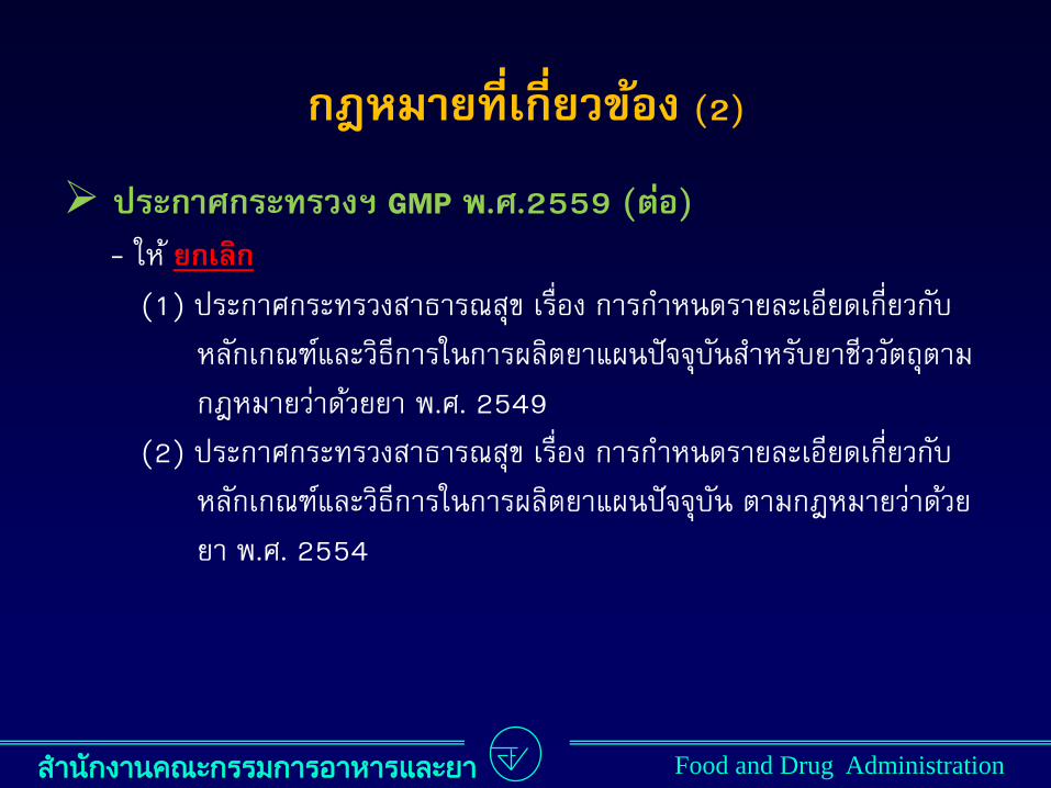
ประกำศกระทรวงฯ GMP พ.ศ.2559 (ตอ)
- ให ยกเลก
(1) ประกาศกระทรวงสาธารณสข เรอง การก าหนดรายละเอยดเกยวกบ
หลกเกณฑและวธการในการผลตยาแผนปจจบนส าหรบยาชววตถตาม
กฎหมายวาดวยยา พ.ศ. 2549
(2) ประกาศกระทรวงสาธารณสข เรอง การก าหนดรายละเอยดเกยวกบ
หลกเกณฑและวธการในการผลตยาแผนปจจบน ตามกฎหมายวาดวย
ยา พ.ศ. 2554
ส ำนกงำนคณะกรรมกำรอำหำรและยำ Food and Drug Administration
กฎหมำยทเกยวของ (3)
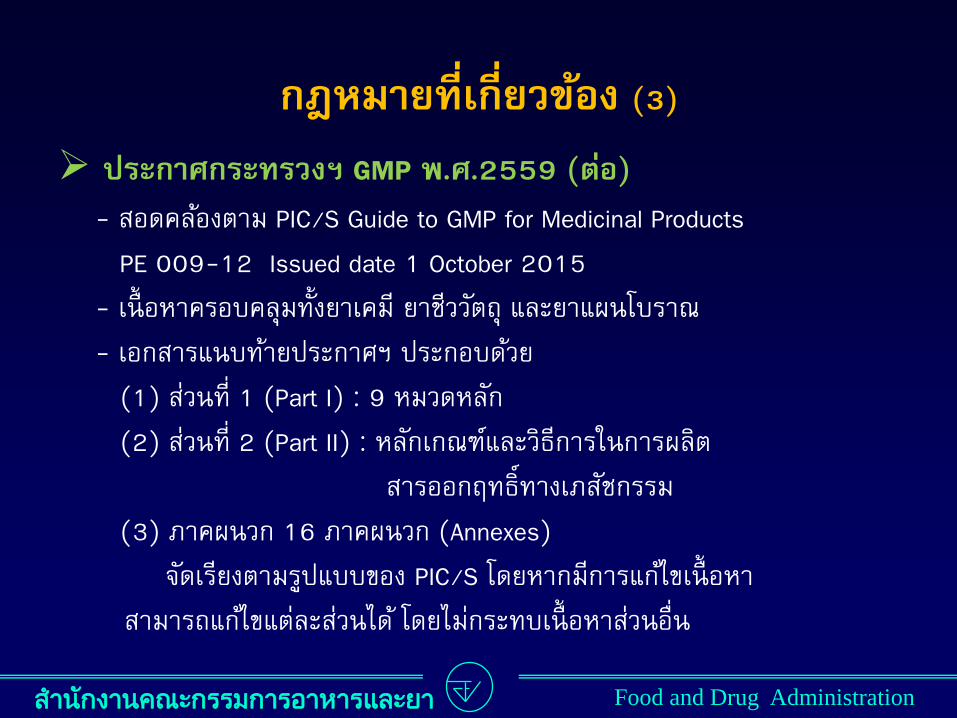
ประกำศกระทรวงฯ GMP พ.ศ.2559 (ตอ)
- สอดคลองตาม PIC/S Guide to GMP for Medicinal Products
PE 009-12 Issued date 1 October 2015
- เนอหาครอบคลมทงยาเคม ยาชววตถ และยาแผนโบราณ
- เอกสารแนบทายประกาศฯ ประกอบดวย
(1) สวนท 1 (Part I) : 9 หมวดหลก
(2) สวนท 2 (Part II) : หลกเกณฑและวธการในการผลต
สารออกฤทธทางเภสชกรรม
(3) ภาคผนวก 16 ภาคผนวก (Annexes)
จดเรยงตามรปแบบของ PIC/S โดยหากมการแกไขเนอหา
สามารถแกไขแตละสวนได โดยไมกระทบเนอหาสวนอน
ส ำนกงำนคณะกรรมกำรอำหำรและยำ Food and Drug Administration
กฎหมำยทเกยวของ (4)
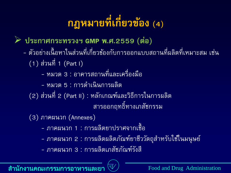
ประกำศกระทรวงฯ GMP พ.ศ.2559 (ตอ)
- ตวอยางเนอหาในสวนทเกยวของกบการออกแบบสถานทผลตทเหมาะสม เชน
(1) สวนท 1 (Part I)
- หมวด 3 : อาคารสถานทและเครองมอ
- หมวด 5 : การด าเนนการผลต
(2) สวนท 2 (Part II) : หลกเกณฑและวธการในการผลต
สารออกฤทธทางเภสชกรรม
(3) ภาคผนวก (Annexes)
- ภาคผนวก 1 : การผลตยาปราศจากเช อ
- ภาคผนวก 2 : การผลตผลตภณฑยาชววตถส าหรบใชในมนษย
- ภาคผนวก 3 : การผลตเภสชภณฑรงส
ส ำนกงำนคณะกรรมกำรอำหำรและยำ Food and Drug Administration
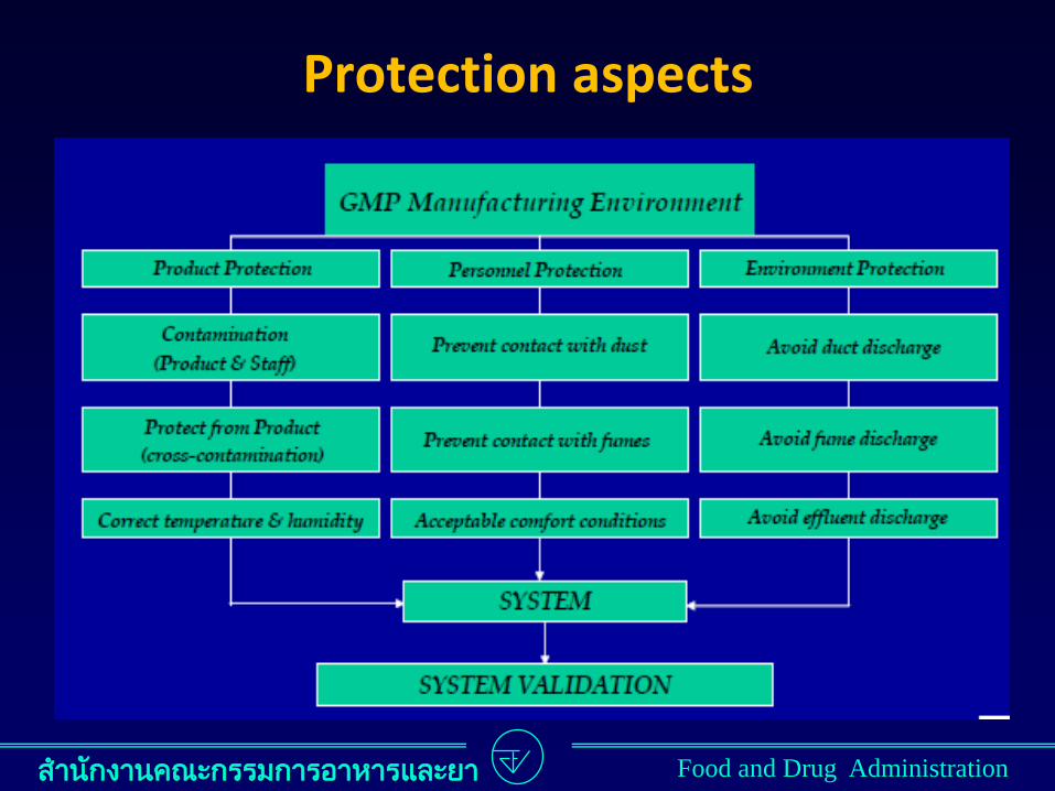
Protection aspects
ส ำนกงำนคณะกรรมกำรอำหำรและยำ Food and Drug Administration
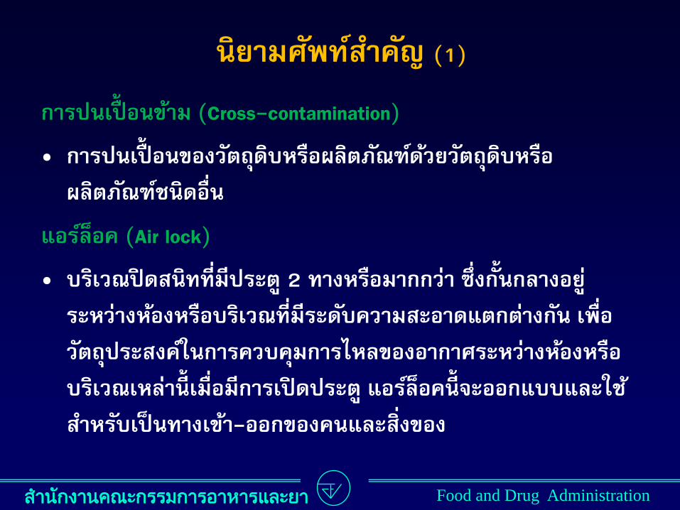
กำรปนเปอนขำม (Cross-contamination)
• กำรปนเปอนของวตถดบหรอผลตภณฑดวยวตถดบหรอ
ผลตภณฑชนดอน
แอรลอค (Air lock)
• บรเวณปดสนททมประต 2 ทำงหรอมำกกวำ ซงกนกลำงอย
ระหวำงหองหรอบรเวณทมระดบควำมสะอำดแตกตำงกน เพอ
วตถประสงคในกำรควบคมกำรไหลของอำกำศระหวำงหองหรอ
บรเวณเหลำนเมอมกำรเปดประต แอรลอคนจะออกแบบและใช
ส ำหรบเปนทำงเขำ-ออกของคนและสงของ
นยำมศพทส ำคญ (1)
ส ำนกงำนคณะกรรมกำรอำหำรและยำ Food and Drug Administration
นยำมศพทส ำคญ (2)
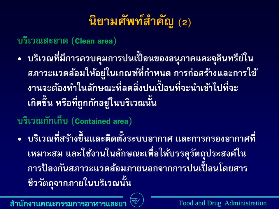
บรเวณสะอำด (Clean area)
• บรเวณทมกำรควบคมกำรปนเปอนของอนภำคและจลนทรยใน
สภำวะแวดลอมใหอยในเกณฑทก ำหนด กำรกอสรำงและกำรใช
งำนจะตองท ำในลกษณะทลดสงปนเปอนทจะน ำเขำไปทจะ
เกดขน หรอทถกกกอยในบรเวณนน
บรเวณกกเกบ (Contained area)
• บรเวณทสรำงขนและตดตงระบบอำกำศ และกำรกรองอำกำศท
เหมำะสม และใชงำนในลกษณะเพอใหบรรลวตถประสงคใน
กำรปองกนสภำวะแวดลอมภำยนอกจำกกำรปนเปอนโดยสำร
ชววตถจำกภำยในบรเวณนน

ส ำนกงำนคณะกรรมกำรอำหำรและยำ Food and Drug Administration
เทคนคหลกเลยงกำรปนเปอนขำม (1)
ประกำศกระทรวงฯ GMP พ.ศ.2559 (หมวด 5 ขอ 19)
ด ำเนนกำรผลตในบรเวณแยกตำงหำก ซงเปนขอก ำหนดส ำหรบ
ผลตภณฑพวกเพนซลลน วคซนทมชวต ผลตภณฑแบคทเรยทม
ชวต และผลตภณฑชววตถบำงชนด หรอท ำกำรผลตโดยกำร
แยกเวลำผลต หลงจำกนนใหท ำควำมสะอำดอยำงเหมำะสม
จดใหม “แอรลอค” และกำรก ำจดอำกำศตำมควำมเหมำะสม
ใหมกำรกรองอำกำศทหมนเวยนหรออำกำศทน ำกลบเขำมำใหม
เพอลดควำมเสยงของกำรปนเปอนจำกอำกำศ

ส ำนกงำนคณะกรรมกำรอำหำรและยำ Food and Drug Administration
เกบเครองแตงกำยส ำหรบใชปฏบตงำนไวภำยในบรเวณทท ำ
กำรผลตผลตภณฑทมควำมเสยงเปนพเศษทท ำใหเกดกำร
ปนเปอนขำม
ใชวธกำรท ำควำมสะอำดและกำรก ำจดสงปนเปอนทม
ประสทธผล เนองจำกกำรท ำควำมสะอำดเครองมอทไมม
ประสทธผลมกเปนแหลงเกดกำรปนเปอนขำม
ใช “ระบบปด” ในกำรด ำเนนกำรผลต
มกำรทดสอบสำรตกคำงและใชฉลำกแสดงสถำนะสะอำด
ตดทเครองมอทผำนกำรท ำควำมสะอำดแลว
เทคนคหลกเลยงกำรปนเปอนขำม (2)
ส ำนกงำนคณะกรรมกำรอำหำรและยำ Food and Drug Administration
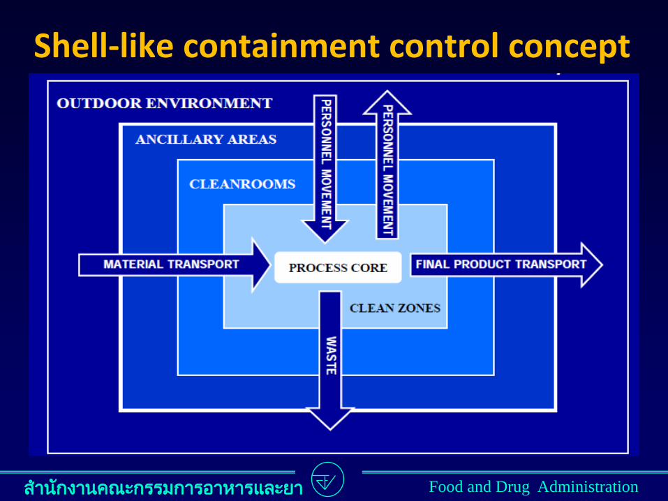
Shell-like containment control concept
ส ำนกงำนคณะกรรมกำรอำหำรและยำ Food and Drug Administration
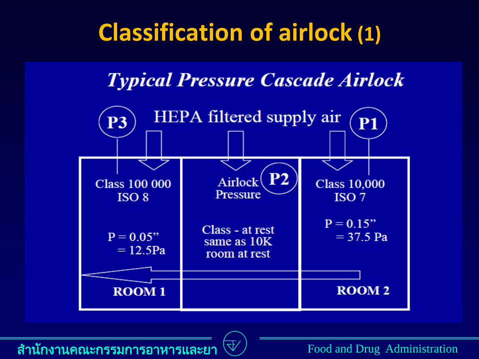
Classification of airlock (1)
ส ำนกงำนคณะกรรมกำรอำหำรและยำ Food and Drug Administration
Classification of airlock (2)
ส ำนกงำนคณะกรรมกำรอำหำรและยำ Food and Drug Administration
Differential pressure
ส ำนกงำนคณะกรรมกำรอำหำรและยำ Food and Drug Administration
Type of “Clean area”
ส ำนกงำนคณะกรรมกำรอำหำรและยำ Food and Drug Administration
1. Conventional (Non-unidirectional flow or turbulently ventilated)
ส ำนกงำนคณะกรรมกำรอำหำรและยำ Food and Drug Administration
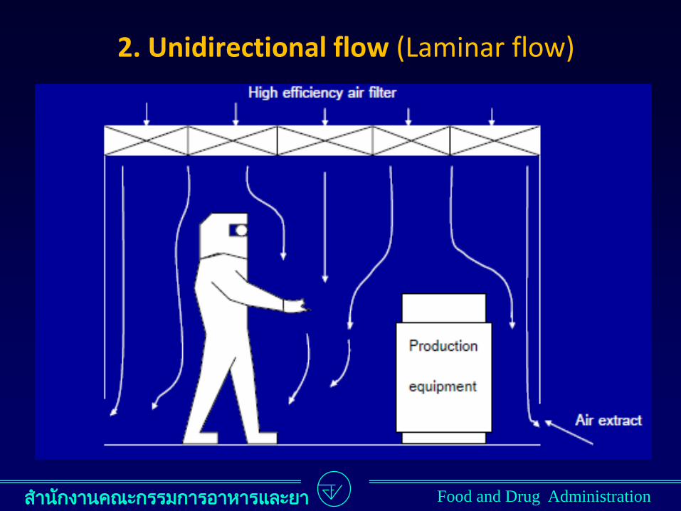
2. Unidirectional flow (Laminar flow)

ส ำนกงำนคณะกรรมกำรอำหำรและยำ Food and Drug Administration
3. Mixed flow
ส ำนกงำนคณะกรรมกำรอำหำรและยำ Food and Drug Administration
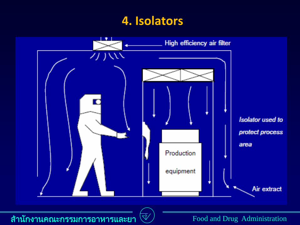
4. Isolators

ส ำนกงำนคณะกรรมกำรอำหำรและยำ Food and Drug Administration
Perforated plate diffuser (recommended)
ส ำนกงำนคณะกรรมกำรอำหำรและยำ Food and Drug Administration
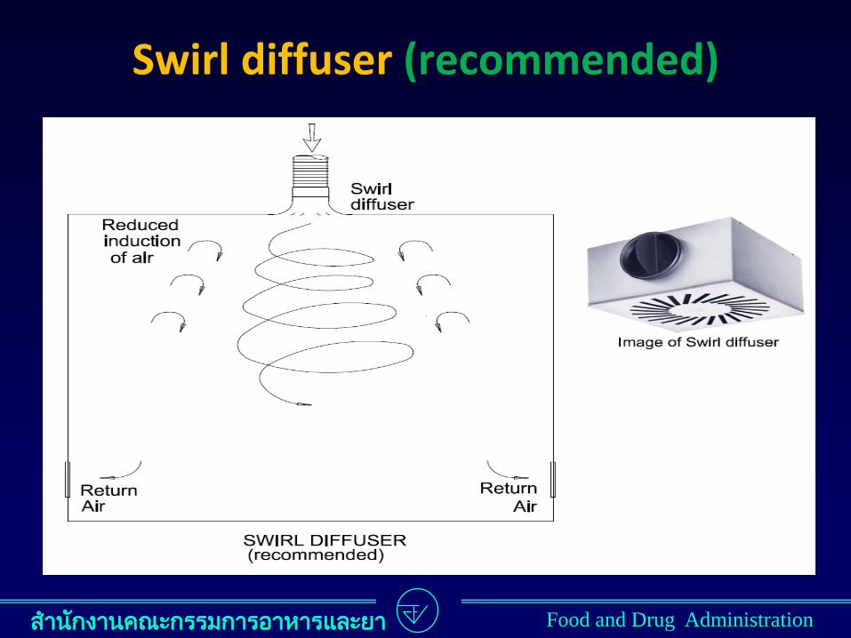
Swirl diffuser (recommended)
ส ำนกงำนคณะกรรมกำรอำหำรและยำ Food and Drug Administration
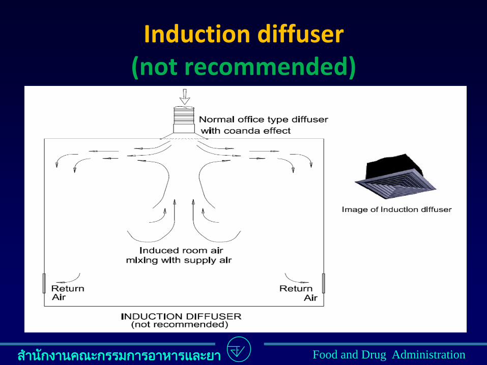
Induction diffuser (not recommended)
ส ำนกงำนคณะกรรมกำรอำหำรและยำ Food and Drug Administration
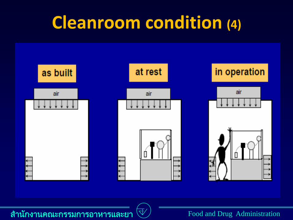
• The “as built” state is the condition where the installation is complete with all services connected and functioning but with no production equipment, materials, or personnel presents.
Cleanroom condition (1)
ส ำนกงำนคณะกรรมกำรอำหำรและยำ Food and Drug Administration
• The “at rest” state is the condition where the installation is installed and operating, complete with production equipment but with no operating personnel present.
ประกำศกระทรวงฯ GMP พ.ศ.2559
• สถำนะ “ไมมกำรปฏบตงำน” เปนสภำวะทมกำรตดตงระบบและเปดใชงำน พรอมทงมกำรท ำงำนของเครองมอผลต แตไมม
ผปฏบตงำนอยในบรเวณนน
Cleanroom condition (2)
ส ำนกงำนคณะกรรมกำรอำหำรและยำ Food and Drug Administration
• The “in operation” state is the condition where the installation is functioning in the defined operating mode with the specified number of personnel working.
ประกำศกระทรวงฯ GMP พ.ศ.2559
• สถำนะ “ก ำลงปฏบตงำน” เปนสภำวะทมกำรเปดใชงำนระบบทตดตงไวตำมวธกำรใชทก ำหนด พรอมทงมผปฏบตงำนก ำลง
ปฏบตงำนตำมจ ำนวนทระบ
Cleanroom condition (3)
ส ำนกงำนคณะกรรมกำรอำหำรและยำ Food and Drug Administration
Cleanroom condition (4)
ส ำนกงำนคณะกรรมกำรอำหำรและยำ Food and Drug Administration
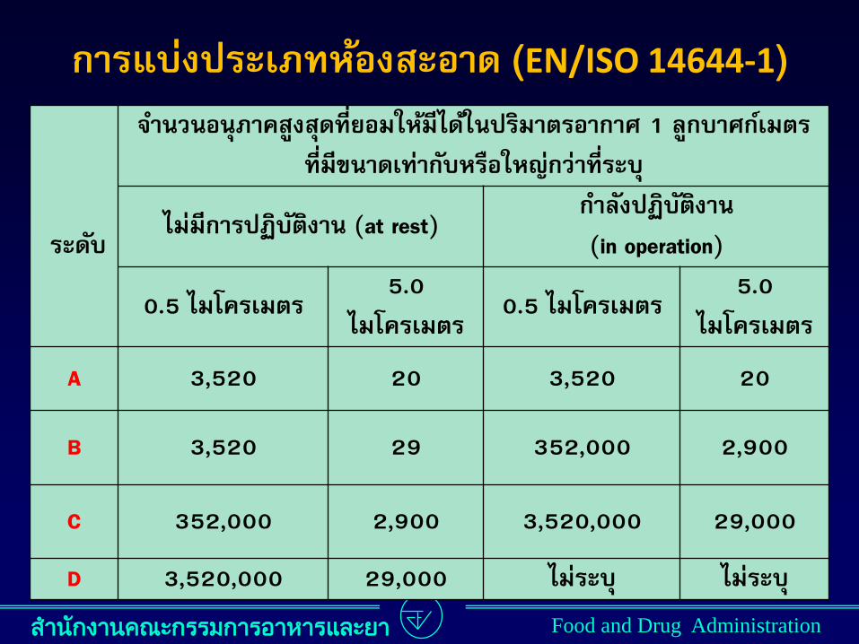
กำรแบงประเภทหองสะอำด (EN/ISO 14644-1)
ระดบ
จ ำนวนอนภำคสงสดทยอมใหมไดในปรมำตรอำกำศ 1 ลกบำศกเมตร
ทมขนำดเทำกบหรอใหญกวำทระบ
ไมมกำรปฏบตงำน (at rest) ก ำลงปฏบตงำน
(in operation)
0.5 ไมโครเมตร 5.0
ไมโครเมตร 0.5 ไมโครเมตร
5.0
ไมโครเมตร
A 3,520 20 3,520 20
B 3,520 29 352,000 2,900
C 352,000 2,900 3,520,000 29,000
D 3,520,000 29,000 ไมระบ ไมระบ
ส ำนกงำนคณะกรรมกำรอำหำรและยำ Food and Drug Administration
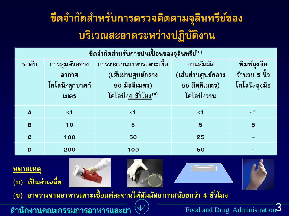
ขดจ ำกดส ำหรบกำรตรวจตดตำมจลนทรยของ
บรเวณสะอำดระหวำงปฏบตงำน
3
1
ขดจ ำกดส ำหรบกำรปนเปอนของจลนทรย (ก)
ระดบ กำรสมตวอยำง
อำกำศ
โคโลน/ลกบำศก
เมตร
กำรวำงจำนอำหำรเพำะเชอ
(เสนผำนศนยกลำง
90 มลลเมตร)
โคโลน/4 ชวโมง(ข)
จำนสมผส
(เสนผำนศนยกลำง
55 มลลเมตร)
โคโลน/จำน
พมพถงมอ
จ ำนวน 5 นว
โคโลน/ถงมอ
A <1 <1 <1 <1
B 10 5 5 5
C 100 50 25 -
D 200 100 50 -
หมำยเหต
(ก) เปนคำเฉลย
(ข) อำจวำงจำนอำหำรเพำะเชอแตละจำนใหสมผสอำกำศนอยกวำ 4 ชวโมง
ส ำนกงำนคณะกรรมกำรอำหำรและยำ Food and Drug Administration
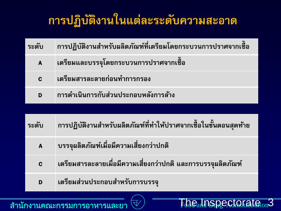
กำรปฏบตงำนในแตละระดบควำมสะอำด
The Inspectorate
Unit, Bureau of
Dug Control,
Thai Food and
Drug
Administration
3
2
ระดบ กำรปฏบตงำนส ำหรบผลตภณฑทท ำใหปรำศจำกเชอในขนตอนสดทำย
A บรรจผลตภณฑเมอมควำมเสยงกวำปกต
C เตรยมสำรละลำยเมอมควำมเสยงกวำปกต และกำรบรรจผลตภณฑ
D เตรยมสวนประกอบส ำหรบกำรบรรจ
ระดบ กำรปฏบตงำนส ำหรบผลตภณฑทเตรยมโดยกระบวนกำรปรำศจำกเชอ
A เตรยมและบรรจโดยกระบวนกำรปรำศจำกเชอ
C เตรยมสำรละลำยกอนท ำกำรกรอง
D กำรด ำเนนกำรกบสวนประกอบหลงกำรลำง

ส ำนกงำนคณะกรรมกำรอำหำรและยำ Food and Drug Administration
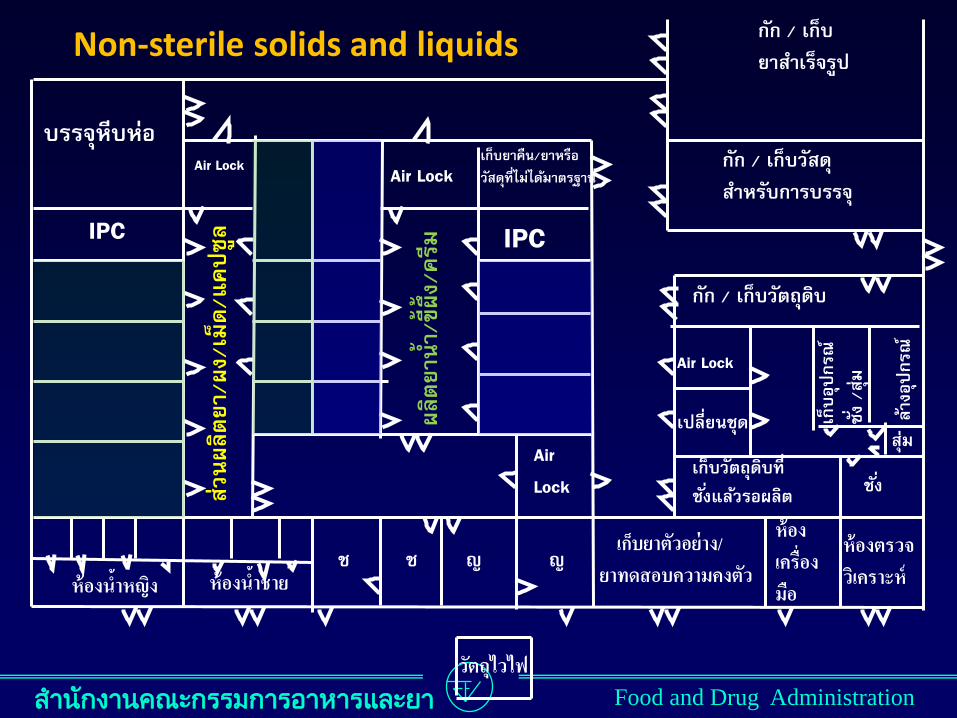
ตวอยำง
แบบแปลนสถำนทผลตยำแตละประเภท
ส ำนกงำนคณะกรรมกำรอำหำรและยำ Food and Drug Administration
กก / เกบ
ยำส ำเรจรป
กก / เกบวสด
ส ำหรบกำรบรรจ
กก / เกบวตถดบ
เกบยำคน/ยำหรอ
วสดทไมไดมำตรฐำน
IPC
Air Lock
ผลตยำน
ำ/ขผง/ครม
Air
Lock
บรรจหบหอ
IPC
หองน ำหญง หองน ำชำย
Air Lock
สวนผลตยำ/ผง/เมด/แคปซล
ช ช ญ ญ
Air Lock
เกบอปกรณ
ชง /สม
ลำงอปกรณ
เปลยนชด สม
ชง เกบวตถดบท
ชงแลวรอผลต
เกบยำตวอยำง/ ยำทดสอบควำมคงตว
หอง เครอง มอ
หองตรวจ วเครำะห
วตถไวไฟ
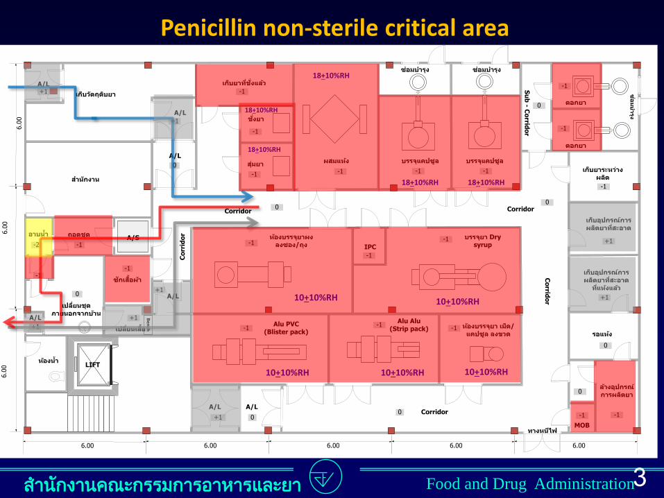
Non-sterile solids and liquids
ส ำนกงำนคณะกรรมกำรอำหำรและยำ Food and Drug Administration
Dry syrup
6.00
6.00
6.00
/
Corridor
IPC
A/L
6.00 6.00
LIFT
6.00 6.00 6.00
0+1
A/L
A/S
-2
-1
-1
+1
Be
nch
A/L
A/L
A/L
A/L
Co
rrid
or
Alu Alu(Strip pack) /
0
Alu PVC(Blister pack)
Corridor
Co
rrido
r
Corridor
Su
b - C
orrid
or
0-1 -1
-1
+1
+1
0
-1
-1
0
0
-1-1-1
-1
-1
-1
0
+1
+1
+1A/L
+1
-1
-1
-1
-1-1
-1
0
0
MOB
-1
10+10%RH 10+10%RH 10+10%RH
10+10%RH 10+10%RH
18+10%RH
18+10%RH
18+10%RH
18+10%RH 18+10%RH
Penicillin non-sterile critical area
35

ส ำนกงำนคณะกรรมกำรอำหำรและยำ Food and Drug Administration
ส ำนกงำนคณะกรรมกำรอำหำรและยำ Food and Drug Administration

ส ำนกงำนคณะกรรมกำรอำหำรและยำ Food and Drug Administration
Thank you for your attention

PLANNING OF PHARMACEUTICAL FACTORIES CONCEPT AND IMPLEMENTATION
PEOPLE AND PLANNING
A Quote:
“You do not really understand something
unless you can explain it to your grandmother."
Albert Einstein
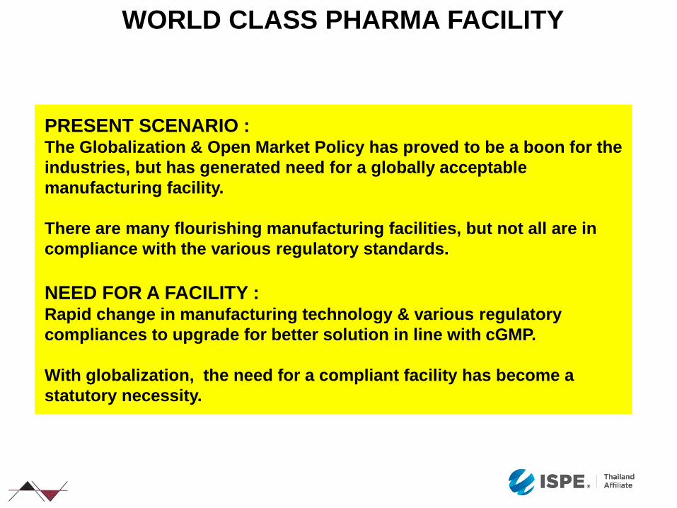
WORLD CLASS PHARMA FACILITY
PRESENT SCENARIO : The Globalization & Open Market Policy has proved to be a boon for the
industries, but has generated need for a globally acceptable
manufacturing facility.
There are many flourishing manufacturing facilities, but not all are in
compliance with the various regulatory standards.
NEED FOR A FACILITY : Rapid change in manufacturing technology & various regulatory
compliances to upgrade for better solution in line with cGMP.
With globalization, the need for a compliant facility has become a
statutory necessity.
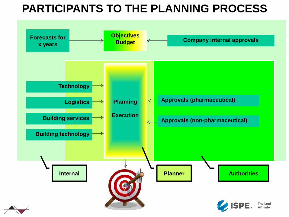
PARTICIPANTS TO THE PLANNING PROCESS
Forecasts for
x years
Objectives
Budget Company internal approvals
Technology
Logistics
Building services
Building technology
Approvals (pharmaceutical)
Approvals (non-pharmaceutical)
Planning
Execution
Internal Planner Authorities
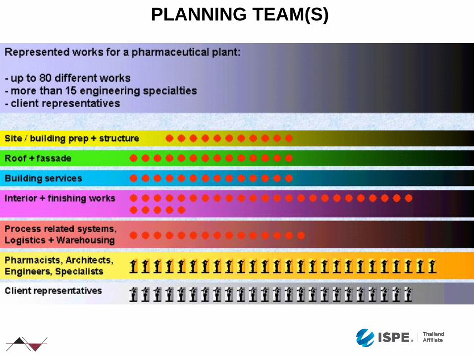
PLANNING TEAM(S)
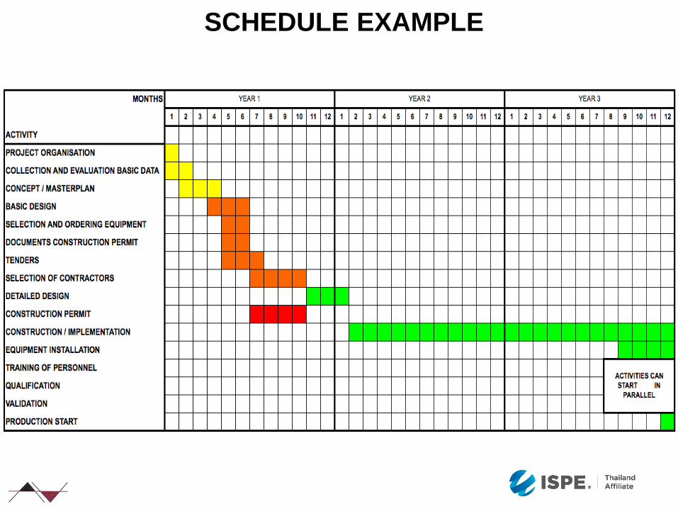
SCHEDULE EXAMPLE
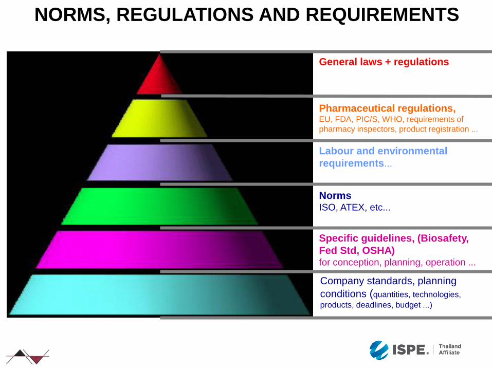
Company standards, planning
conditions (quantities, technologies,
products, deadlines, budget ...)
Specific guidelines, (Biosafety,
Fed Std, OSHA) for conception, planning, operation ...
Norms ISO, ATEX, etc...
Labour and environmental
requirements...
Pharmaceutical regulations, EU, FDA, PIC/S, WHO, requirements of
pharmacy inspectors, product registration ...
NORMS, REGULATIONS AND REQUIREMENTS
General laws + regulations
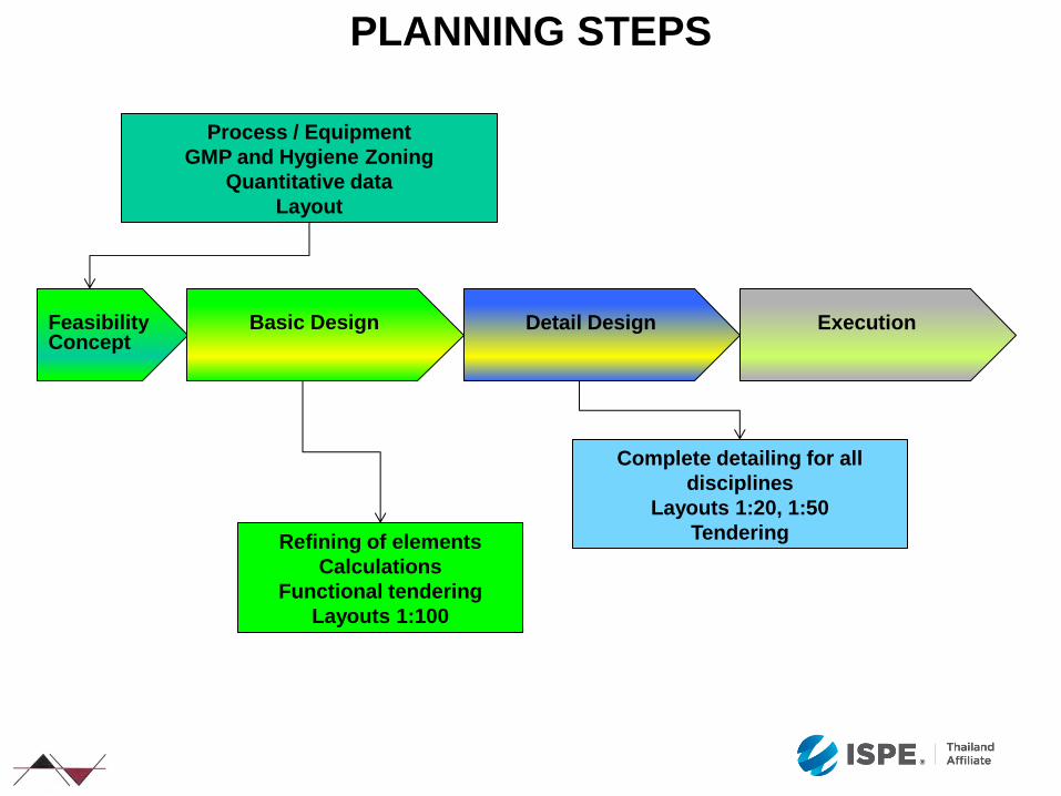
Process / Equipment
GMP and Hygiene Zoning
Quantitative data
Layout
Feasibility Concept
Basic Design
Detail Design
Execution
Complete detailing for all
disciplines
Layouts 1:20, 1:50
Tendering Refining of elements
Calculations
Functional tendering
Layouts 1:100
PLANNING STEPS
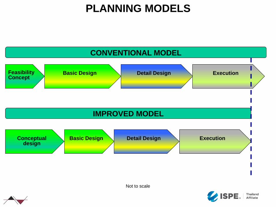
Feasibility Concept
Basic Design
Detail Design
Execution
Conceptual
design
Basic Design
Detail Design
Execution
CONVENTIONAL MODEL
IMPROVED MODEL
PLANNING MODELS
Not to scale
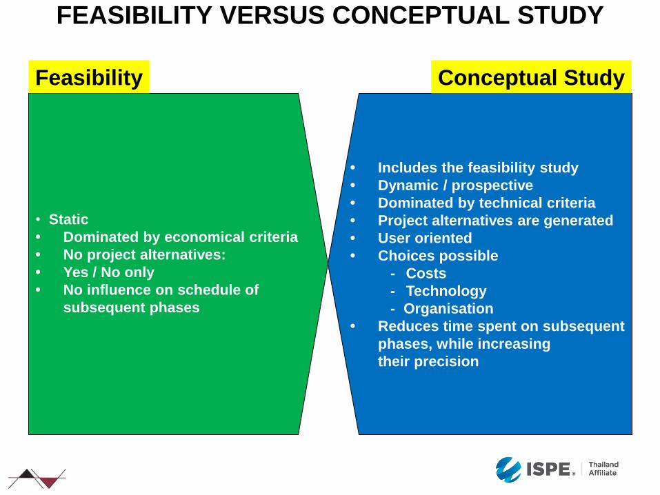
FEASIBILITY VERSUS CONCEPTUAL STUDY
• Static
• Dominated by economical criteria
• No project alternatives:
• Yes / No only
• No influence on schedule of
subsequent phases
Feasibility
• Includes the feasibility study
• Dynamic / prospective
• Dominated by technical criteria
• Project alternatives are generated
• User oriented
• Choices possible
- Costs
- Technology
- Organisation
• Reduces time spent on subsequent
phases, while increasing
their precision
Conceptual Study
Strong Conceptual
design
Basic
Design
Detail
Design
Execution
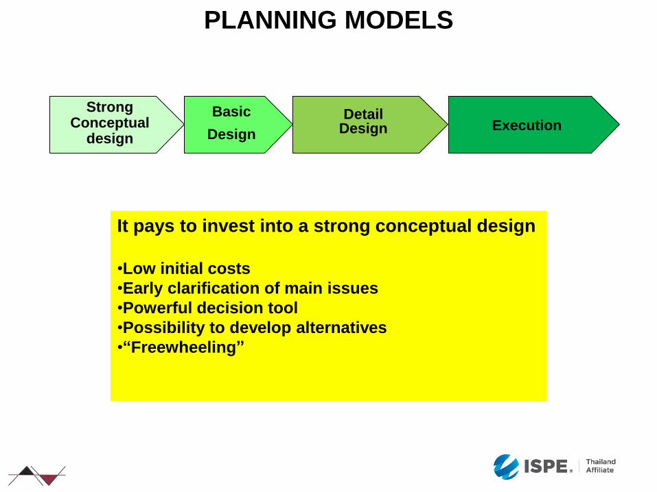
PLANNING MODELS
It pays to invest into a strong conceptual design
•Low initial costs
•Early clarification of main issues
•Powerful decision tool
•Possibility to develop alternatives
•“Freewheeling”

PLANNING SEQUENCE AND ITERATION PROBLEMS
Planning Task Start
Task Definition
Targets Requirements
Analysis
Conceptual Design
with Alternatives
Basic Design
Execution
easy
difficult
Detail Design
100%
90%
80%
60%
50%
40%
30%
20%
10%
70%
100%
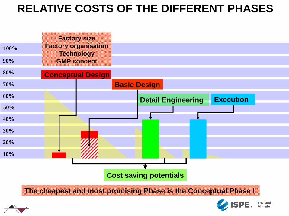
RELATIVE COSTS OF THE DIFFERENT PHASES
The cheapest and most promising Phase is the Conceptual Phase !
Detail Engineering
Factory size
Factory organisation
Technology
GMP concept
Basic Design
Conceptual Design
Execution
Cost saving potentials
100%
90%
80%
70%
60%
50%
40%
30%
20%
10%
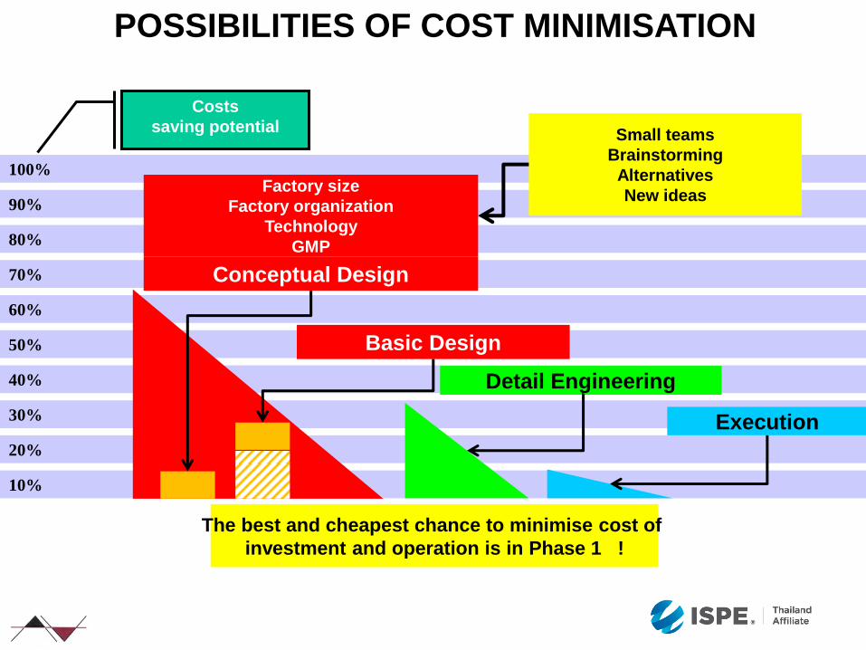
POSSIBILITIES OF COST MINIMISATION
Basic Design
The best and cheapest chance to minimise cost of
investment and operation is in Phase 1 !
Detail Engineering
Execution
Costs
saving potential
Conceptual Design
Factory size
Factory organization
Technology
GMP
Small teams
Brainstorming
Alternatives
New ideas
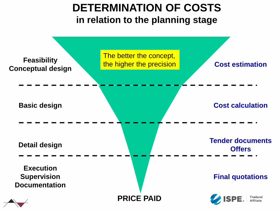
Feasibility
Conceptual design
Basic design
Detail design
Execution
Supervision
Documentation
Cost estimation
Cost calculation
Tender documents
Offers
Final quotations
The better the concept,
the higher the precision
DETERMINATION OF COSTS in relation to the planning stage
PRICE PAID
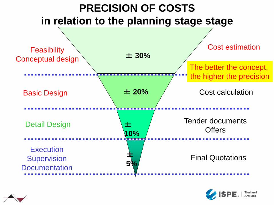
PRECISION OF COSTS
in relation to the planning stage stage
± 30% Cost estimation Feasibility
Conceptual design
±
5% Final Quotations
Execution
Supervision
Documentation
± 20% Cost calculation Basic Design
±
10%
Tender documents
Offers Detail Design
The better the concept,
the higher the precision
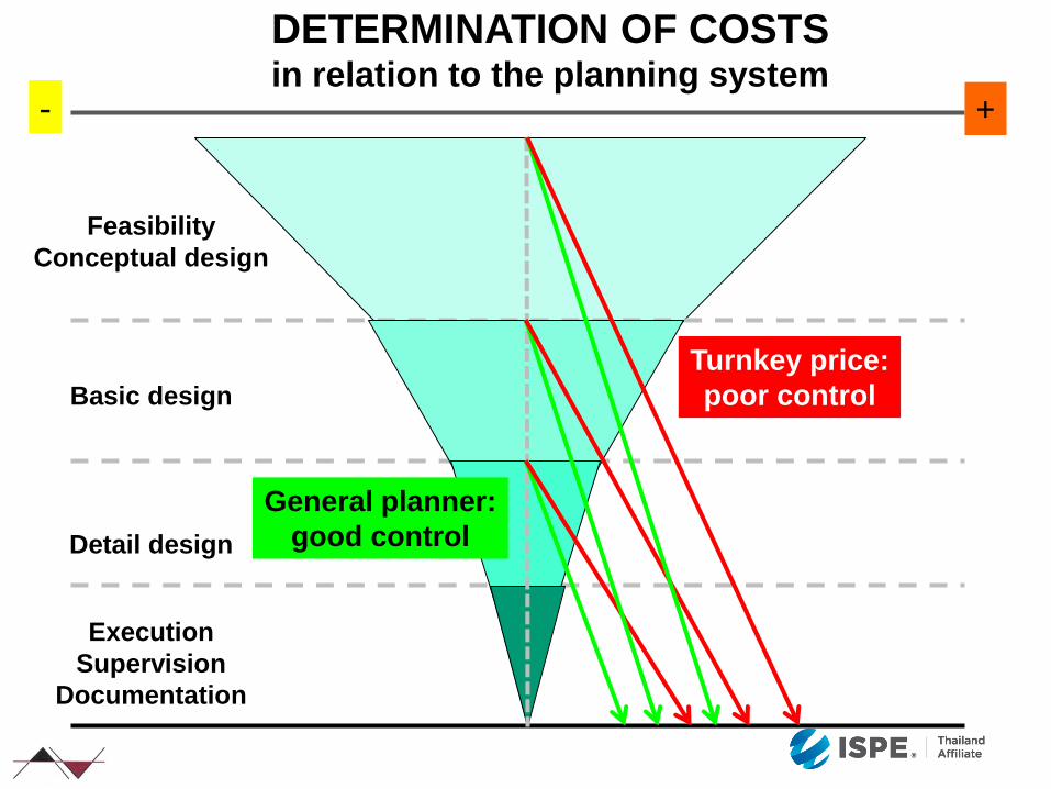
Feasibility
Conceptual design
Basic design
Detail design
Execution
Supervision
Documentation
DETERMINATION OF COSTS in relation to the planning system
Turnkey price:
poor control
General planner:
good control
- +
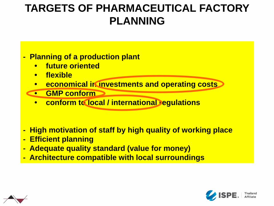
- Planning of a production plant
• future oriented
• flexible
• economical in investments and operating costs
• GMP conform
• conform to local / international regulations
- High motivation of staff by high quality of working place
- Efficient planning
- Adequate quality standard (value for money)
- Architecture compatible with local surroundings
TARGETS OF PHARMACEUTICAL FACTORY
PLANNING
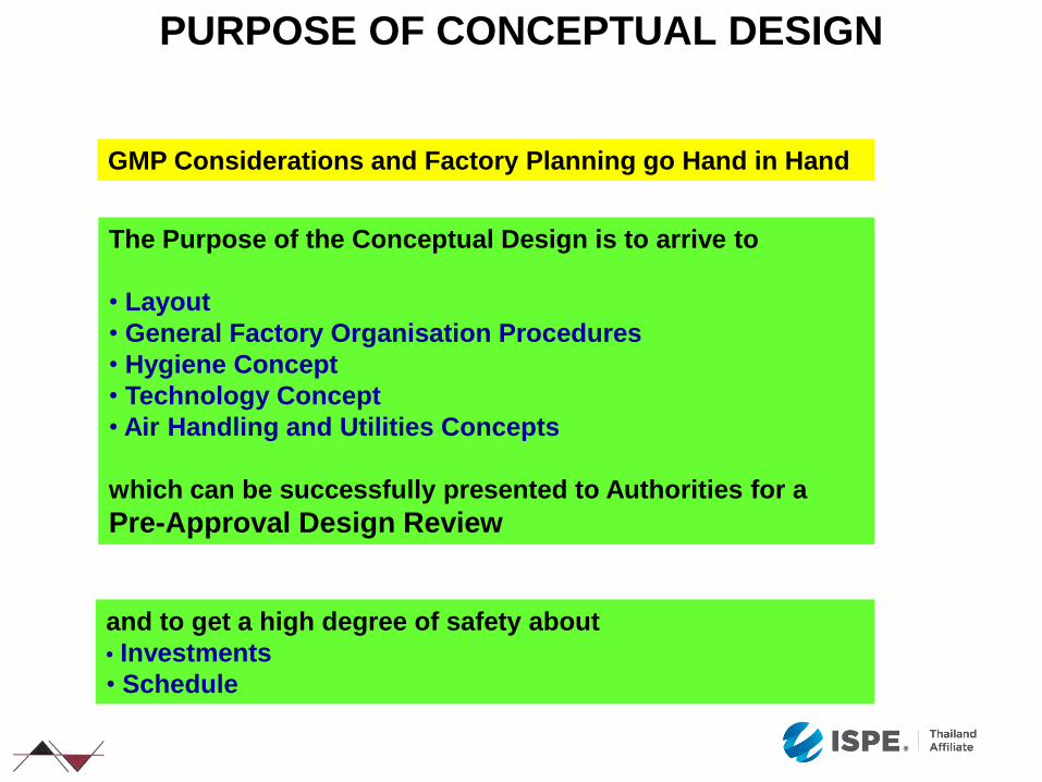
The Purpose of the Conceptual Design is to arrive to
• Layout
• General Factory Organisation Procedures
• Hygiene Concept
• Technology Concept
• Air Handling and Utilities Concepts
which can be successfully presented to Authorities for a
Pre-Approval Design Review
GMP Considerations and Factory Planning go Hand in Hand
PURPOSE OF CONCEPTUAL DESIGN
and to get a high degree of safety about
• Investments
• Schedule
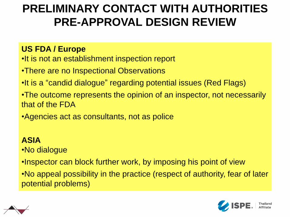
US FDA / Europe
•It is not an establishment inspection report
•There are no Inspectional Observations
•It is a “candid dialogue” regarding potential issues (Red Flags)
•The outcome represents the opinion of an inspector, not necessarily
that of the FDA
•Agencies act as consultants, not as police
ASIA
•No dialogue
•Inspector can block further work, by imposing his point of view
•No appeal possibility in the practice (respect of authority, fear of later
potential problems)
PRELIMINARY CONTACT WITH AUTHORITIES
PRE-APPROVAL DESIGN REVIEW
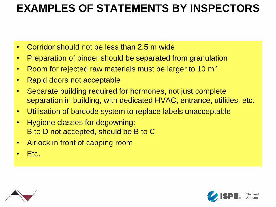
EXAMPLES OF STATEMENTS BY INSPECTORS
• Corridor should not be less than 2,5 m wide
• Preparation of binder should be separated from granulation
• Room for rejected raw materials must be larger to 10 m2
• Rapid doors not acceptable
• Separate building required for hormones, not just complete
separation in building, with dedicated HVAC, entrance, utilities, etc.
• Utilisation of barcode system to replace labels unacceptable
• Hygiene classes for degowning:
B to D not accepted, should be B to C
• Airlock in front of capping room
• Etc.

Although binder preparation dedicated to the line, and
preparation of binder just-in-time, obligation to have separate
room and corridor: loss of space, no apparent benefit
EXAMPLES
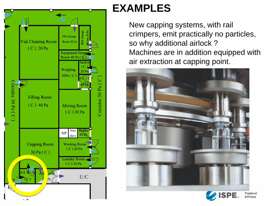
New capping systems, with rail
crimpers, emit practically no particles,
so why additional airlock ?
Machines are in addition equipped with
air extraction at capping point.
EXAMPLES
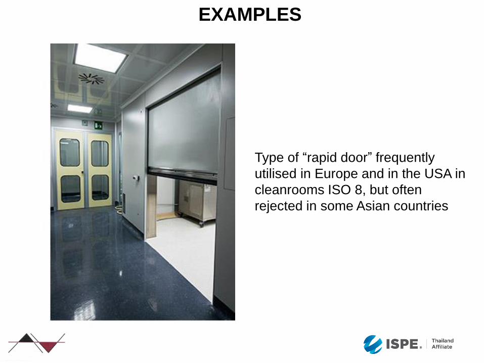
Type of “rapid door” frequently
utilised in Europe and in the USA in
cleanrooms ISO 8, but often
rejected in some Asian countries
EXAMPLES

HOW TO REACH
A GOOD CONCEPTUAL DESIGN RESULT ?
Right team
Good method
Discipline
Good data
Some fantasy
Right team
Good method
Discipline
Good data
Some fantasy
Right team
Good method
Discipline
Good data
Some fantasy
Right team
Good method
Discipline
Good data
Some fantasy
Right team
Good method
Discipline
Good data
Some fantasy
PEOPLE AND PLANNING
A Quote:
“You do not really understand something
unless you can explain it to your grandmother."
Albert Einstein
The idea is to work intensively with a small group
of people, possibly detached from their daily
chores.
These people must have the necessary know-how
(or back-ups) and the power of decision
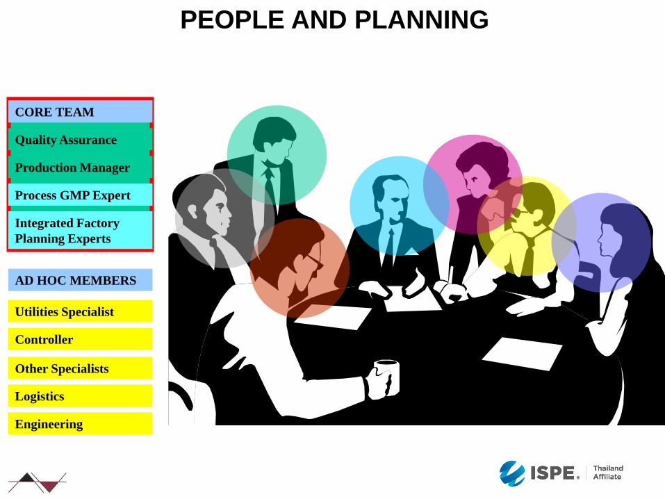
CORE TEAM
Production Manager
Quality Assurance
Integrated Factory
Planning Experts
Process GMP Expert
Controller
AD HOC MEMBERS
Utilities Specialist
Other Specialists
Logistics
Engineering
PEOPLE AND PLANNING

Generalists Specialists
Execution Detail Design Conceptual Design Basic Design
PLANNING
VALIDATION
Generalists Specialists
Number of people
Number of people
PEOPLE AND PLANNING

90%
100%
80%
70%
60%
50%
40%
30%
20%
10%
Individuals
Concept
Team
Large
Organisations
Jud
gem
ent
Err
ors
Number of Participants
Role of Participants :
To plan AND to decide
JUDGEMENT ERRORS
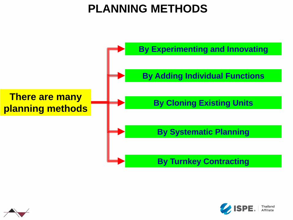
By Experimenting and Innovating
By Cloning Existing Units
By Adding Individual Functions
By Turnkey Contracting
PLANNING METHODS
There are many
planning methods
By Systematic Planning
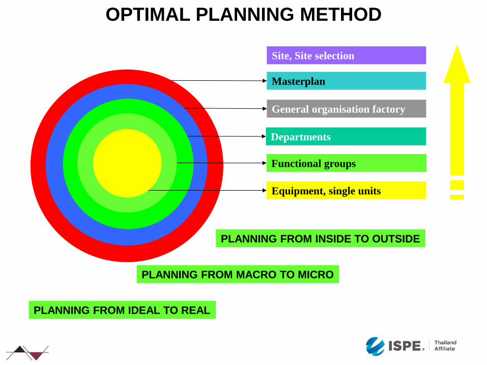
Masterplan
General organisation factory
Site, Site selection
Departments
Functional groups
Equipment, single units
PLANNING FROM INSIDE TO OUTSIDE
PLANNING FROM MACRO TO MICRO
PLANNING FROM IDEAL TO REAL
OPTIMAL PLANNING METHOD
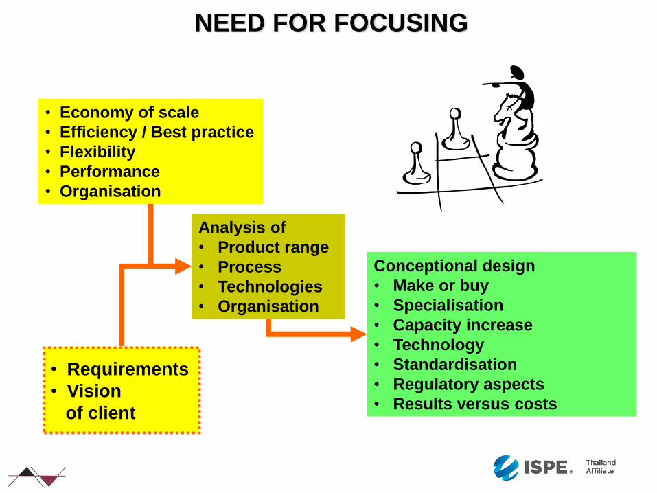
NEED FOR FOCUSING
• Economy of scale
• Efficiency / Best practice
• Flexibility
• Performance
• Organisation
Analysis of
• Product range
• Process
• Technologies
• Organisation
Conceptional design
• Make or buy
• Specialisation
• Capacity increase
• Technology
• Standardisation
• Regulatory aspects
• Results versus costs
• Requirements
• Vision
of client
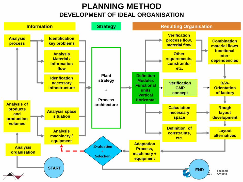
PLANNING METHOD DEVELOPMENT OF IDEAL ORGANISATION
Information Strategy
Identification
key problems
Analysis
Material /
Information
flow
Idenfication
necessary
infrastructure
Analysis
process
START
Definition
Modules
Functional
units
Vertical
Horizontal
Resulting Organisation
END
Verification
process flow,
material flow
Other
requirements,
constraints,
etc.
Calculation
necessary
space
Definition of
constraints,
etc.
Adaptation
Process,
machinery +
equipment
Evaluation
+
Selection
Plant
strategy
+
Process
architecture
Rough
layout
development
Layout
alternatives
Combination
material flows
functional
inter-
dependencies
B/W-
Orientation
of factory
Analysis
organisation
Analysis space
situation
Analysis
machinery /
equipment
Analysis of
products
and
production
volumes
Verification
GMP
concept

Morphological Analysis + Search for Solutions Capacity and Rationalisation Analysis
Existing
Technology GMP-Concept
Technological
Alternatives
Investment /
Budget
Forecasts,
Quantities,
Product Mix
Batch Sizes
Galenical
Properties
Degree of
Automation
Project-
Technology
Degree of
Automation
Batch Sizes
Shifts ?
Product
Seasonality
Campaign Sizes
Cleaning +
Change-over
Times
Foreseen
Equipment
Dimension.
Machines
(Type/
Quantity)
PLANNING METHOD RATIONALISATION, INNOVATION AND OPTIMISATION
GMP-Concept
Plant
strategy
+
Process
architecture
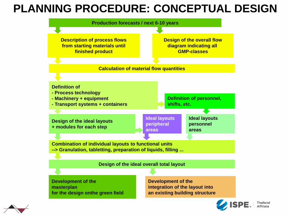
PLANNING PROCEDURE: CONCEPTUAL DESIGN
Development of the
masterplan
for the design onthe green field
Development of the
integration of the layout into
an existing building structure
Production forecasts / next 6-10 years
Description of process flows
from starting materials until
finished product
Design of the overall flow
diagram indicating all
GMP-classes
Calculation of material flow quantities
Definition of personnel,
shifts, etc.
Design of the ideal layouts
+ modules for each step
Ideal layouts
personnel
areas
Ideal layouts
peripheral
areas
Combination of individual layouts to functional units
--> Granulation, tabletting, preparation of liquids, filling ...
Design of the ideal overall total layout
Definition of
- Process technology
- Machinery + equipment
- Transport systems + containers
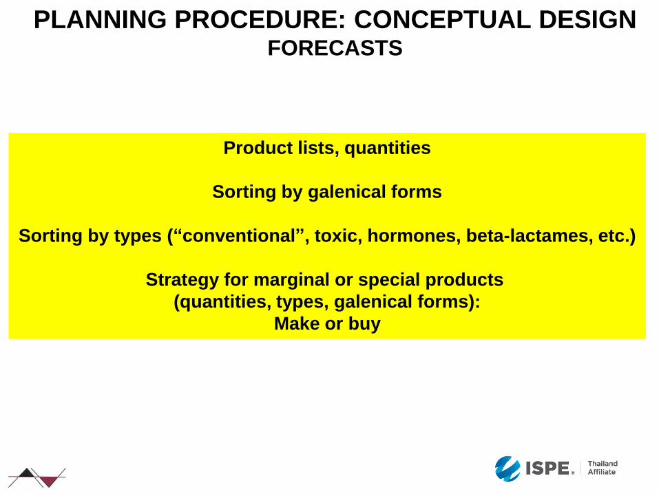
PLANNING PROCEDURE: CONCEPTUAL DESIGN FORECASTS
Product lists, quantities
Sorting by galenical forms
Sorting by types (“conventional”, toxic, hormones, beta-lactames, etc.)
Strategy for marginal or special products
(quantities, types, galenical forms):
Make or buy
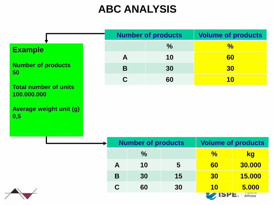
ABC ANALYSIS
Number of products Volume of products
% %
A 10 60
B 30 30
C 60 10
Number of products Volume of products
% % kg
A 10 5 60 30.000
B 30 15 30 15.000
C 60 30 10 5.000
Example
Number of products
50
Total number of units
100.000.000
Average weight unit (g)
0,5
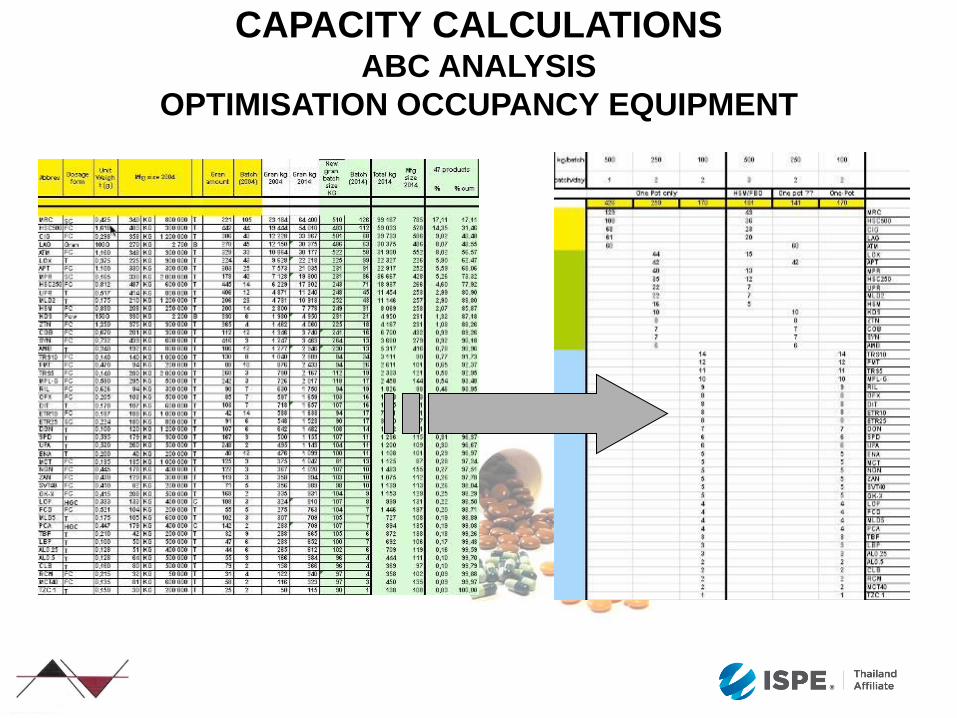
CAPACITY CALCULATIONS ABC ANALYSIS
OPTIMISATION OCCUPANCY EQUIPMENT
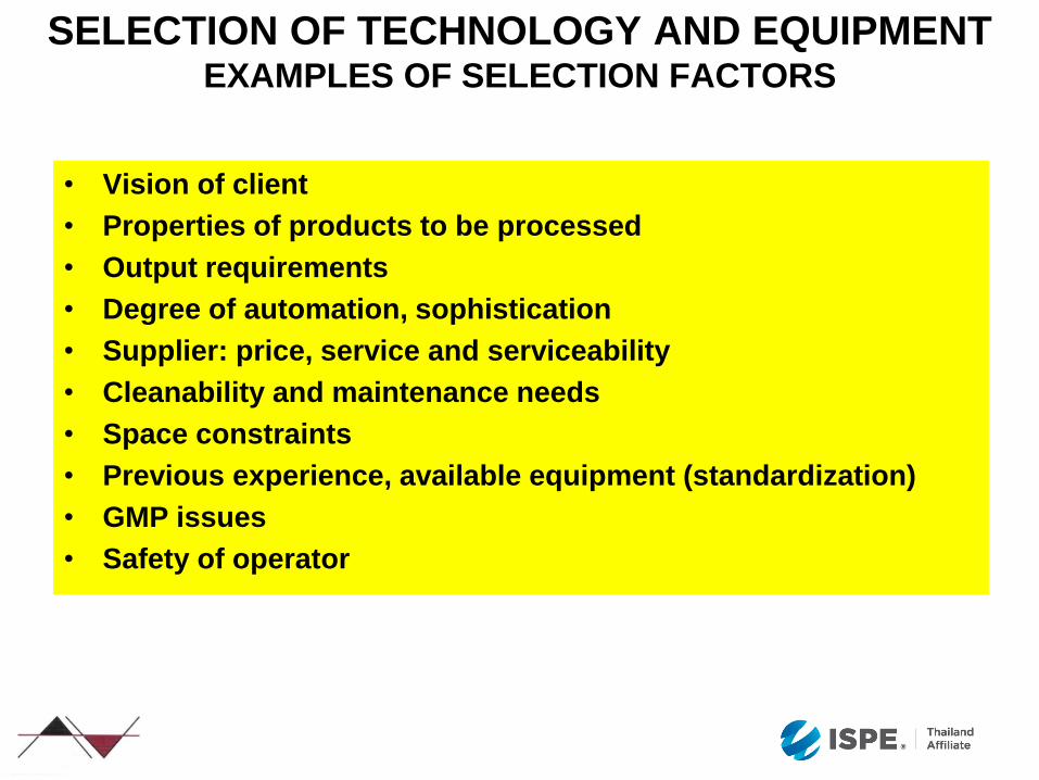
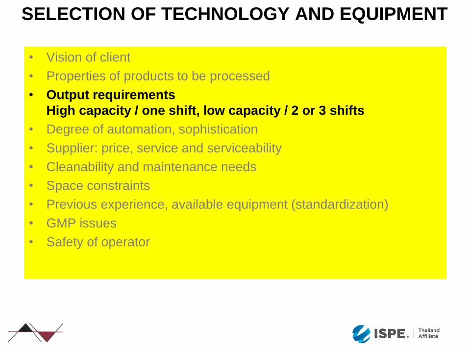
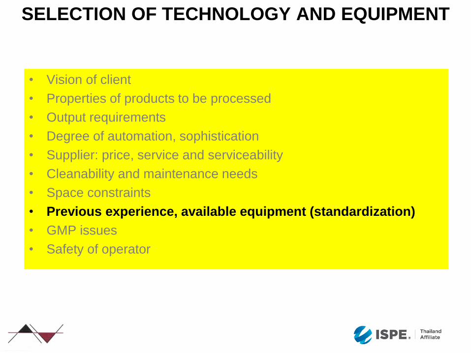
SELECTION OF TECHNOLOGY AND EQUIPMENT EXAMPLES OF SELECTION FACTORS
• Vision of client
• Properties of products to be processed
• Output requirements
• Degree of automation, sophistication
• Supplier: price, service and serviceability
• Cleanability and maintenance needs
• Space constraints
• Previous experience, available equipment (standardization)
• GMP issues
• Safety of operator
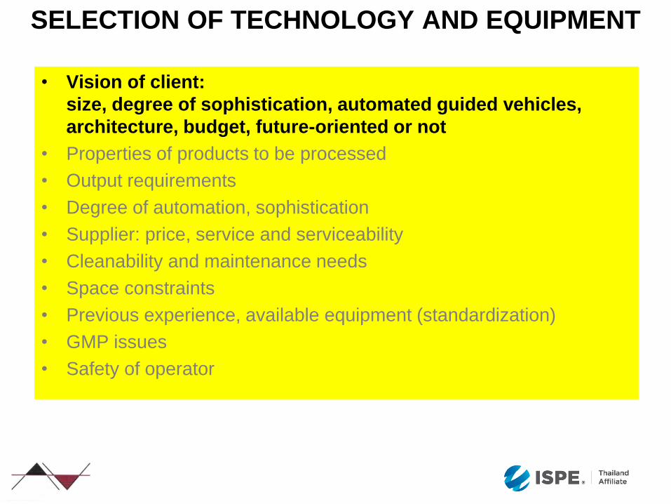
SELECTION OF TECHNOLOGY AND EQUIPMENT
• Vision of client:
size, degree of sophistication, automated guided vehicles,
architecture, budget, future-oriented or not
• Properties of products to be processed
• Output requirements
• Degree of automation, sophistication
• Supplier: price, service and serviceability
• Cleanability and maintenance needs
• Space constraints
• Previous experience, available equipment (standardization)
• GMP issues
• Safety of operator

SELECTION OF TECHNOLOGY AND EQUIPMENT
• Safety of operator
• Vision of client
• Properties of products to be processed:
eg granulation properties: is a direct compression possible or a
dry granulation ?
Aseptic processing or terminal sterilization, ampoules or
syringes
• Output requirements
• Degree of automation, sophistication
• Supplier: price, service and serviceability
• Cleanability and maintenance needs
• Space constraints
• Previous experience, available equipment (standardization)
• GMP issues
SELECTION OF TECHNOLOGY AND EQUIPMENT
• Vision of client
• Properties of products to be processed
• Output requirements
High capacity / one shift, low capacity / 2 or 3 shifts
• Degree of automation, sophistication
• Supplier: price, service and serviceability
• Cleanability and maintenance needs
• Space constraints
• Previous experience, available equipment (standardization)
• GMP issues
• Safety of operator
SELECTION OF TECHNOLOGY AND EQUIPMENT
• Vision of client
• Properties of products to be processed
• Output requirements
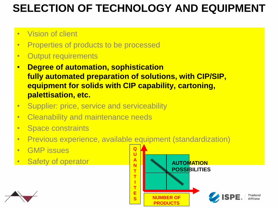
• Degree of automation, sophistication
fully automated preparation of solutions, with CIP/SIP,
equipment for solids with CIP capability, cartoning,
palettisation, etc.
• Supplier: price, service and serviceability
• Cleanability and maintenance needs
• Space constraints
• Previous experience, available equipment (standardization)
• GMP issues
• Safety of operator
NUMBER OF
PRODUCTS
Q
U
A
N
T
T
I
T
E
S
AUTOMATION
POSSIBILITIES
SELECTION OF TECHNOLOGY AND EQUIPMENT
• Vision of client
• Properties of products to be processed
• Output requirements
• Degree of automation, sophistication
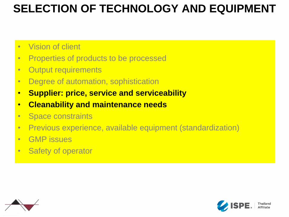
• Supplier: price, service and serviceability
• Cleanability and maintenance needs
• Space constraints
• Previous experience, available equipment (standardization)
• GMP issues
• Safety of operator
SELECTION OF TECHNOLOGY AND EQUIPMENT
• Vision of client
• Properties of products to be processed
• Output requirements
• Degree of automation, sophistication
• Supplier: price, service and serviceability
• Cleanability and maintenance needs
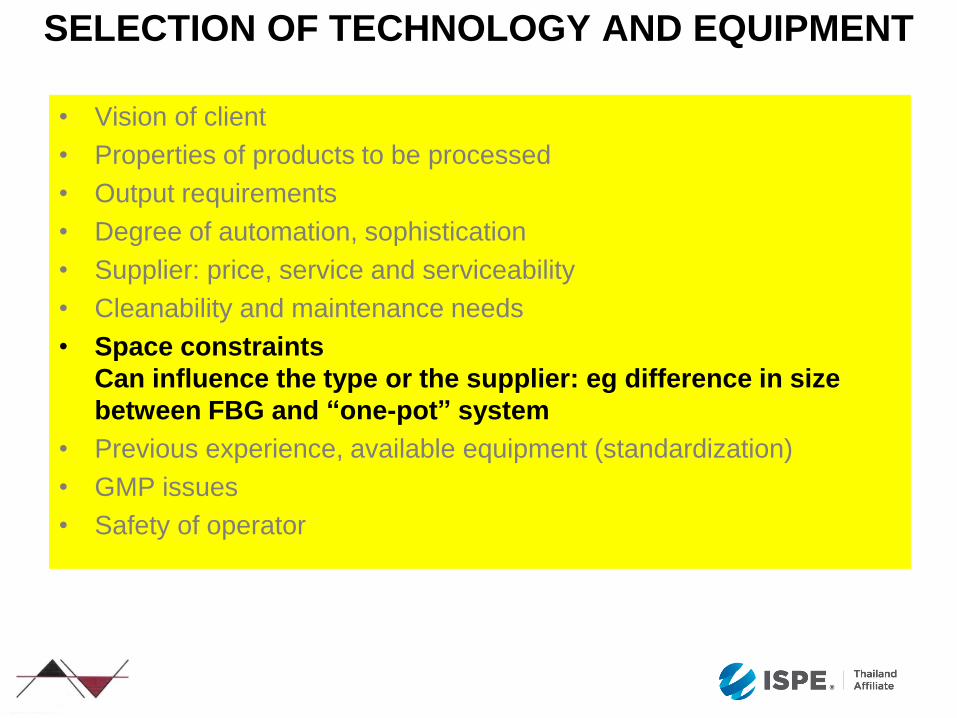
• Space constraints
Can influence the type or the supplier: eg difference in size
between FBG and “one-pot” system
• Previous experience, available equipment (standardization)
• GMP issues
• Safety of operator
SELECTION OF TECHNOLOGY AND EQUIPMENT
• Vision of client
• Properties of products to be processed
• Output requirements
• Degree of automation, sophistication
• Supplier: price, service and serviceability
• Cleanability and maintenance needs
• Space constraints
• Previous experience, available equipment (standardization)
• GMP issues
• Safety of operator
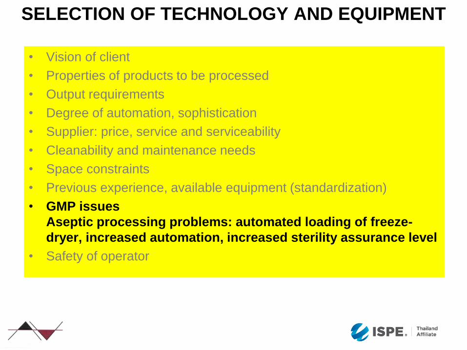
SELECTION OF TECHNOLOGY AND EQUIPMENT
• Vision of client
• Properties of products to be processed
• Output requirements
• Degree of automation, sophistication
• Supplier: price, service and serviceability
• Cleanability and maintenance needs
• Space constraints
• Previous experience, available equipment (standardization)
• GMP issues
Aseptic processing problems: automated loading of freeze-
dryer, increased automation, increased sterility assurance level
• Safety of operator
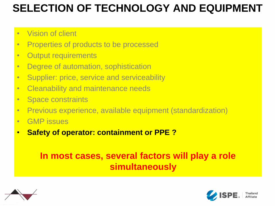
SELECTION OF TECHNOLOGY AND EQUIPMENT
• Vision of client
• Properties of products to be processed
• Output requirements
• Degree of automation, sophistication
• Supplier: price, service and serviceability
• Cleanability and maintenance needs
• Space constraints
• Previous experience, available equipment (standardization)
• GMP issues
• Safety of operator: containment or PPE ?
In most cases, several factors will play a role
simultaneously

ABA ADA ACA
BAA BAE BAD BAC BAB
CAA CAB
DAA DAD DAC DAB
EAA EAC EAB
FAA FAE FAD FAC FAB
GAA GAB
HAA HAC HAB
AAA
BBB
CCC
DDD
EEE
FFF
GGG
HHH
SELECTION OF TECHNOLOGY AND EQUIPMENT MORPHOLOGICAL ANALYSIS
P
R
O
C
E
S
S
S
T
E
P
S
PROCESS ALTERNATIVES

MC
Convent ional mixer Gravit y mixer
M C MC M C
MC MC
A: granules + l ubri cants (+ formulat ions for direct compresi on)
B: t rade powders (+ formulat ions for direct compresi on)
vibrati on sieve
Convent ional mixer
Gravit y mixer
Classi cal granul at i on A. Diosna-method
MC
WSG
WSG
WSG
M C
WSG
Convent i onal mixer
Gravit y mixer
M C
MC
Single Granulat ion
A B
gr avity mixerconvent ional
mixer
WSG WSG
WSG
M C
M C
WSG
MC
M C
WSG
M C
MC
M C
convent ional
mixer
gravit y mixer
A B
WSG
WSG
WSG
WSG
M C
WSG
Doubl e Granul ati on
WSG WSG
Cl assical g ranul ati on B. Vacuumat -Method
M C M C
M C
M C
Convention al mixer
Gravity mix er
M C
MC
P
Tec
hnical a
rea
T P
Personnel+ T ransp o rt Cor rid o r
Feed ing l evel
Technical Ar ea o r Visi to rs
Cor rid o r Personnel
Tech.
MC
Tec
hnical a
rea
T P
Personnel+ T ransp o rt Cor rid o r
P
P
Cor rid o r Personnel
Tech.MC
SELECTION OF TECHNOLOGY AND EQUIPMENT PROCESS SELECTION

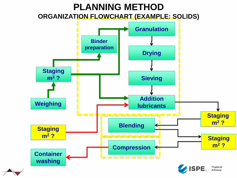
PLANNING METHOD PROCESS AND ORGANIZATION FLOW CHARTS
Whereas a process flow chart reflects the process only,
an organization flow chart includes the process, its
organization as well as additional elements such as
quantities, personnel needs, hygiene zoning, equipment
and inter-relationships within the production or between
production and related functions.
The process flowchart must be transformed into an
organisational flow chart
Organization flow charts exist at different levels, micro-
and macro:
Micro: within a department
Macro: within a production unit / plant

PLANNING METHOD PROCESS FLOWCHART (EXAMPLE: SOLIDS)
Granulation Binder
preparation
Drying
Sieving
Addition
lubricants
Blending
Compression
Granulation
Binder
preparation Drying
Sieving
Addition
lubricants
Blending
Compression
Weighing
Staging
m2 ?
Staging
m2 ?
Staging
m2 ?
Container
washing
Staging
m2 ?
PLANNING METHOD ORGANIZATION FLOWCHART (EXAMPLE: SOLIDS)

PLANNING METHOD FLOWS PERSONNEL AND MATERIALS
Exterior
Lockers G
G
Lockers D
D
Lockers C
C
A/B
Lockers A/B
Exterior
Lockers G
G
Lockers D
D
Lockers C
C
A/B
Lockers A/B
Selection of alternative ESSENTIAL, later changes practically impossible
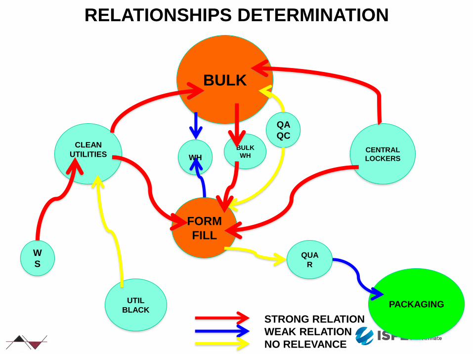
BULK
CLEAN
UTILITIES
FORM
FILL
CENTRAL
LOCKERS
BULK
WH
QA
QC
WH
PACKAGING
QUA
R
W
S
UTIL
BLACK
STRONG RELATION
WEAK RELATION
NO RELEVANCE
RELATIONSHIPS DETERMINATION

PERSONNEL LOCKERS EXAMPLE LAYOUT
Depend on
• Hygiene zone
• Local regulations
• Company / cultural habits to be considered
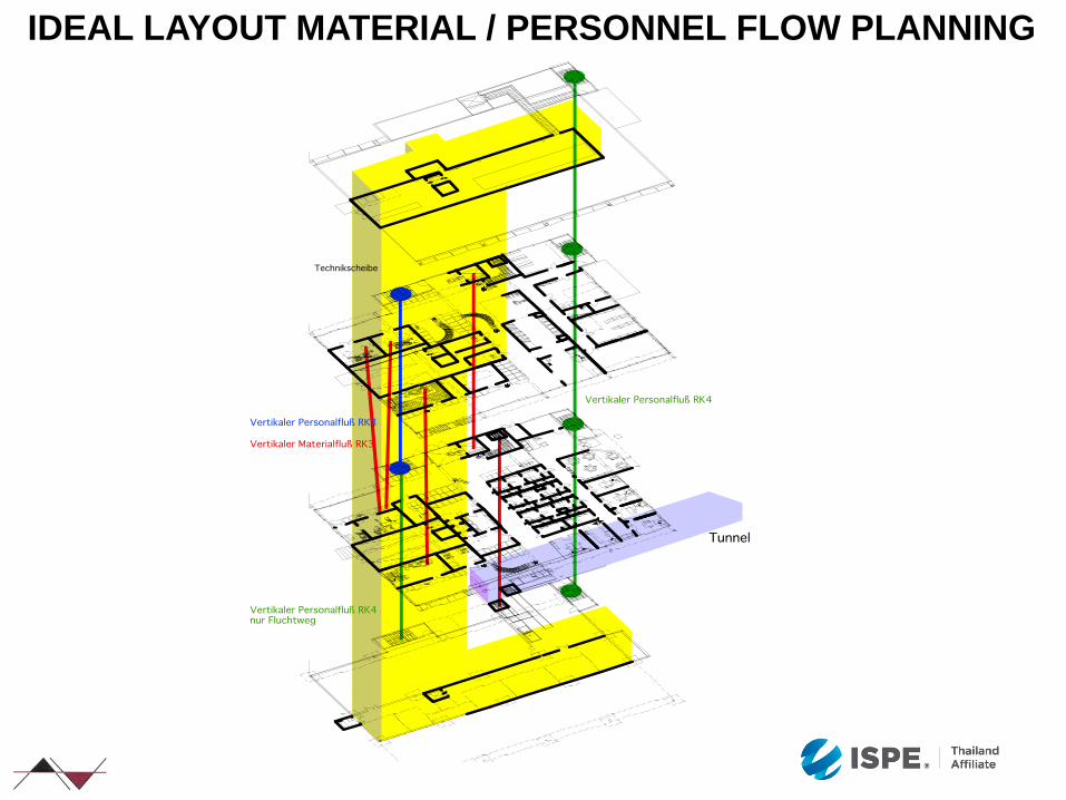
IDEAL LAYOUT MATERIAL / PERSONNEL FLOW PLANNING
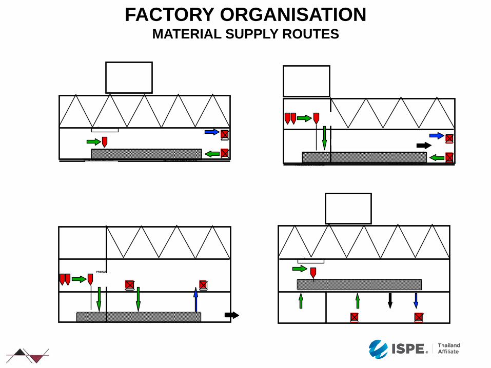
FACTORY ORGANISATION MATERIAL SUPPLY ROUTES
LF
PRIMÄRVERPACKUNG SEKUNDÄRVERPACKUNG
PRIMÄRVERPACKUNG SEKUNDÄRVERPACKUNG
PRIMÄR
LF
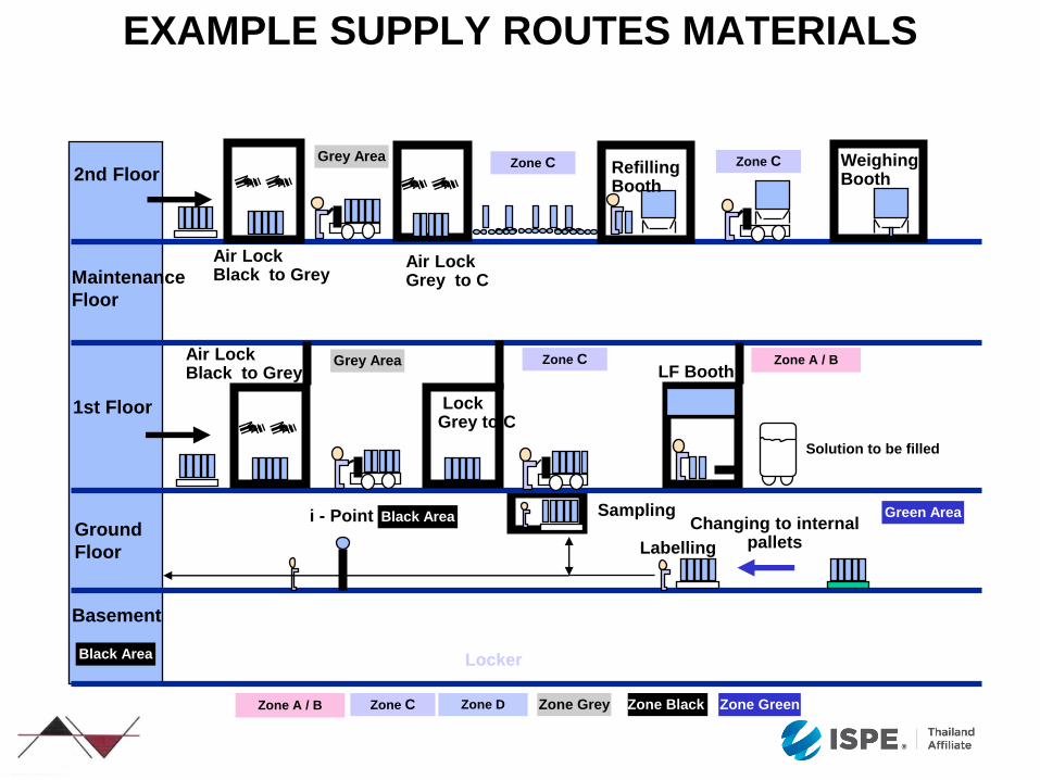
Zone Grey Zone D Zone A / B Zone C Zone Black Zone Green
EXAMPLE SUPPLY ROUTES MATERIALS
Locker
LF Booth
Solution to be filled
Changing to internal pallets Labelling
Sampling i - Point
Refilling Booth
Weighing Booth
Air Lock Grey to C
Lock Grey to C
Air Lock Black to Grey
Black Area Green Area
Black Area
Zone A / B Zone C Grey Area
Basement
1st Floor
Maintenance
Floor
2nd Floor
Ground
Floor
Zone C Zone C Grey Area
Air Lock Black to Grey
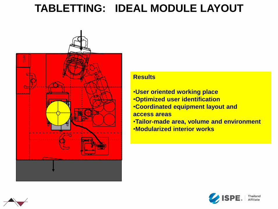
TABLETTING: IDEAL MODULE LAYOUT
C100
Results
•User oriented working place
•Optimized user identification
•Coordinated equipment layout and
access areas
•Tailor-made area, volume and environment
•Modularized interior works
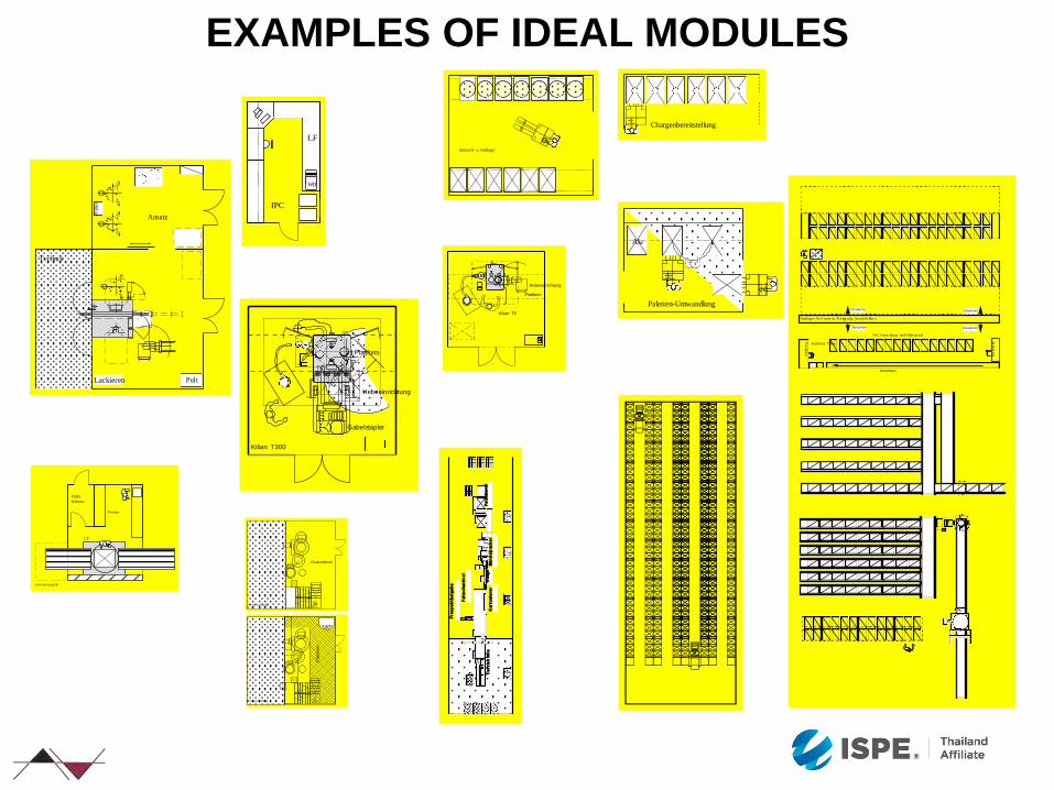
EXAMPLES OF IDEAL MODULES
PultLackieren
Technik
Ansatz
Pu
mp
e
LF
WB
IPC
Anbruch- u. Faßlager
Paletten-Umwandlung
Alu
Kilian T300
Plattform
Hebeeinrichtung
Gabelstapler
PERS.
Schleuse
Entst aubungskab.
Proben
LF
Pac
ktis
che
Rol lenbahn
Pac
ktisch
Kommiss. Pakete
Pa l. Verpa ckungs -und Füllm ate ri al
Handlager für Komm iss. Fe rt igpackg. (verschlie ßba r)
Entnahme
EntnahmeEntnahme
Entnahme
Chargenbereitstellung
Kilian TX
Plattform
Hebeeinrichtung
Prozesstechnik
Granulation
Prozesstechnik
Pla
ttfo
rm
Tie
fz
ieh
foli
eK
arto
nie
re
rW
aag
eB
ün
de
lpac
ke
rP
ale
ttie
re
r
Falt
sc
hac
ht
el
Pro
sp
ek
tb
eig
ab
e
FROM IDEAL MODULE TO FACTORY LAYOUT
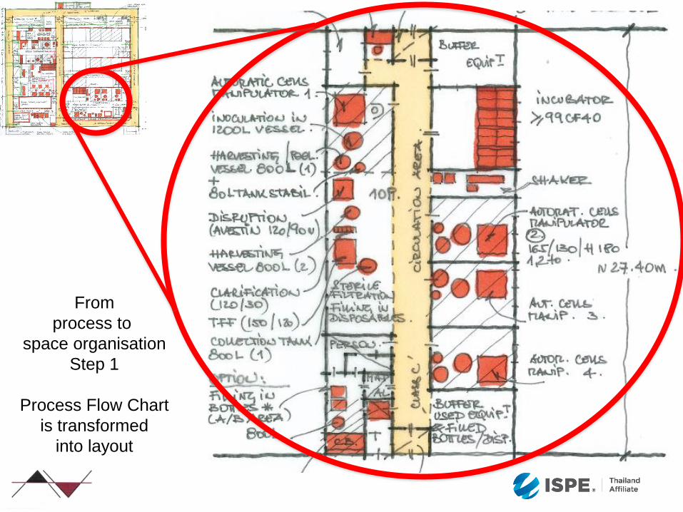
From
process to
space organisation
Step 1
Process Flow Chart
is transformed
into layout
From
process to
space organisation
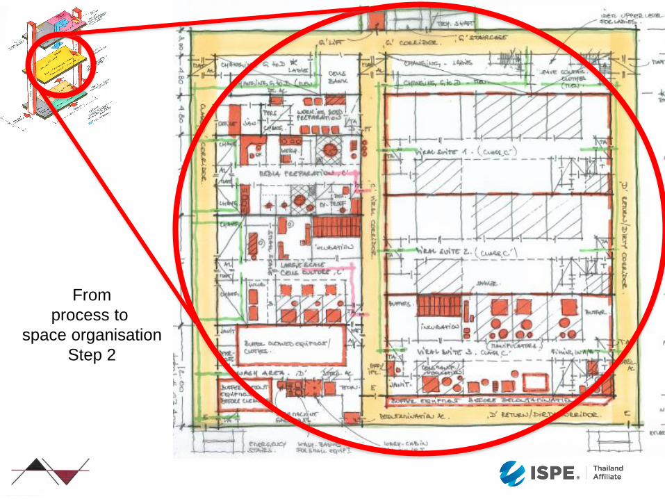
Step 2
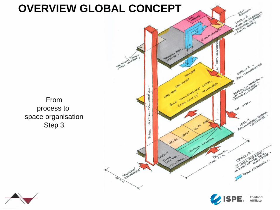
OVERVIEW GLOBAL CONCEPT
From
process to
space organisation
Step 3
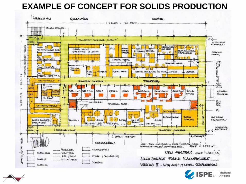
EXAMPLE OF CONCEPT FOR SOLIDS PRODUCTION
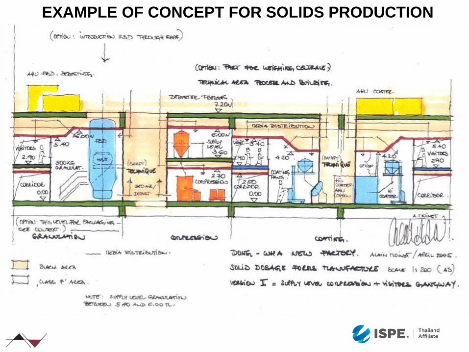
EXAMPLE OF CONCEPT FOR SOLIDS PRODUCTION
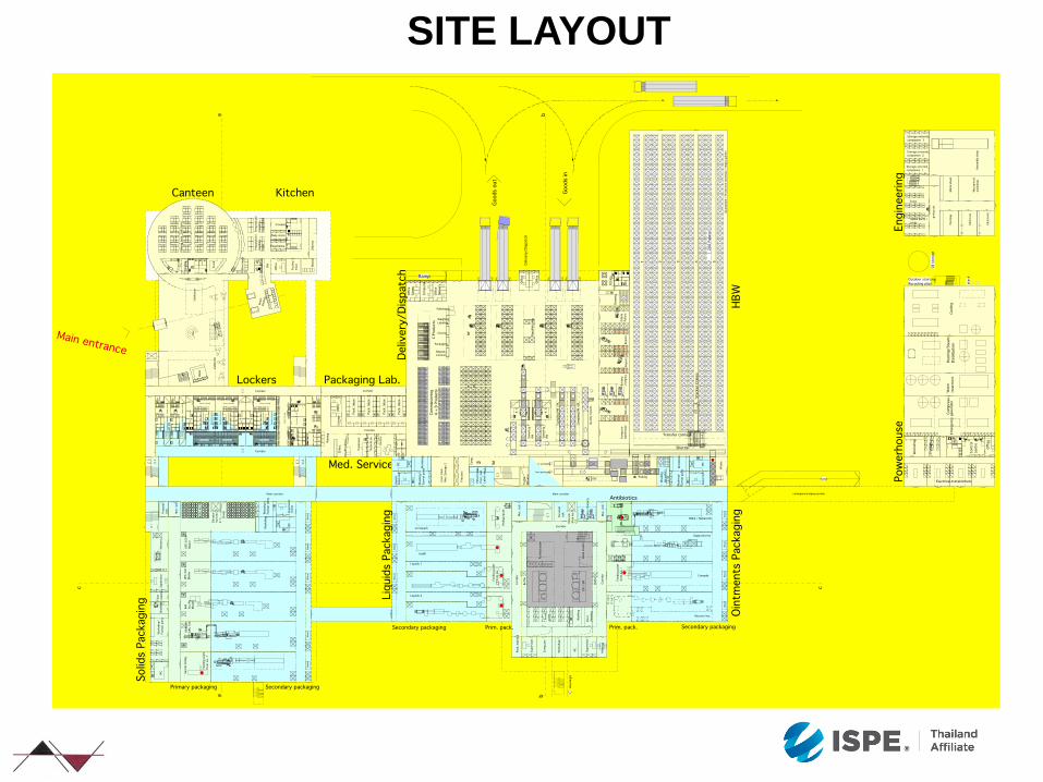
SITE LAYOUT
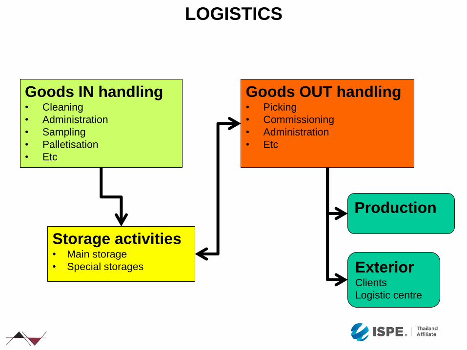
LOGISTICS
Goods IN handling • Cleaning
• Administration
• Sampling
• Palletisation
• Etc
Storage activities • Main storage
• Special storages
Goods OUT handling • Picking
• Commissioning
• Administration
• Etc
Production
Exterior Clients
Logistic centre

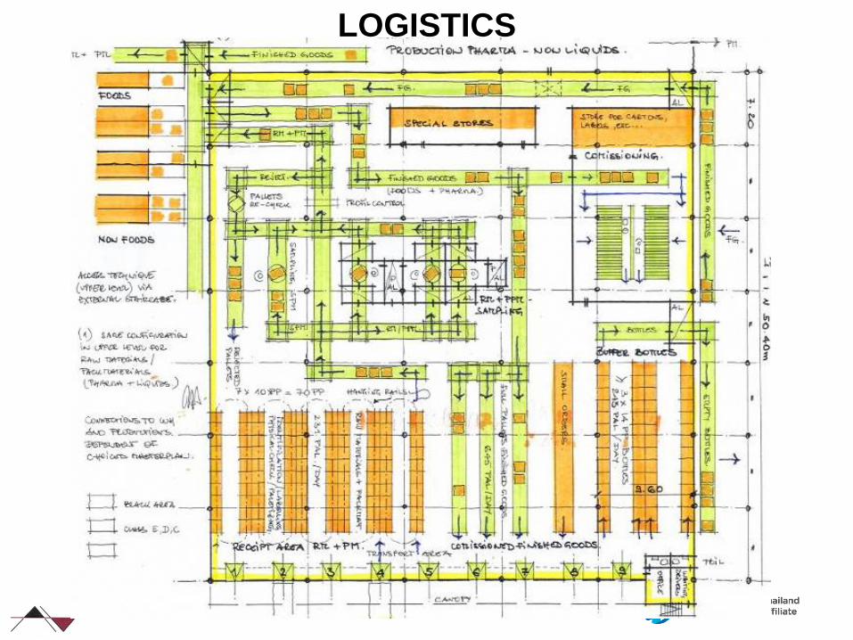
LOGISTICS Raw material
Primary packaging material
Secundary packaging material
Finished products
Receiving
area
Pre
para
tio
n a
rea
for
raw
- a
nd
pri
mary
packag
ing
mate
rial
Sampling
Booth
Shipping
weig
hin
g Production
area
Marshalling
Bu
lk s
tore
Packaging
lines
pal / h
pal / h
pal / h
pal / h pal / h
pal / h pal / h pal / h
pal / h pal / h pal / h
pal / h
pal / h
pal / h
pal / h
Warehouse
Pharma
Storage
capacity:
pallet
places
Sampling
Quarantine separation Change of pallets to/from production
Procedures in material air locks
LOGISTICS

« GOOD GMP »
• Minimized risk of contamination / cross-contamination
• Clear material flows (uni-directional whenever possible)
• Clear personnel flows (uni-directional whenever possible)
• Unambiguous definition of GMP zones
• Separation clean – dirty (washing areas)
• Overkill
• Cost issues
• Nice to have
• GMP is not an attribute, no black and white attitudes

SUMMARY
A good pharmaceutical factory is a factory that is:
•Pharmaceutically approved (qualification / validation )
•Economical to operate and maintain
•Flexible and adaptable quantity-wise and for new technologies
To design such an excellent pharmaceutical plant, an
integrated, multi-disciplinary and experienced team is required.
The objectives, the vision, the method and the involvement of
each member of the team will achieve this goal, and not the
principle “function follows adding up individual inputs”

75