gmrs proximal tibia global modular replacement...
TRANSCRIPT

GMRS® Proximal Tibia Global Modular
Replacement System
Surgical protocol

GMRS Proximal Tibia surgical protocol
2

GMRS Proximal Tibia surgical protocol
3
GMRS Proximal TibiaSurgical protocol
Contents
Introduction . . . . . . . . . . . . . . . . . . . . . . . . . . . . . . . . . . 2
Description of the Global Modular
Replacement System Proximal Tibia . . . . . . . . . . . . 4
Indications/contraindications . . . . . . . . . . . . . . . . . . 6
Surgical protocol . . . . . . . . . . . . . . . . . . . . . . . . . . . . . . 7
Measuring resection length . . . . . . . . . . . . . . . . . . . . . . . . 8
Tibial osteotomy . . . . . . . . . . . . . . . . . . . . . . . . . . . . . . . . 9
Femoral sizing . . . . . . . . . . . . . . . . . . . . . . . . . . . . . . . . . 9
Preparation for the MRH femoral component . . . . . . . . . 10
Femoral canal preparation . . . . . . . . . . . . . . . . . . . . . 10
Distal femoral resection . . . . . . . . . . . . . . . . . . . . . . . 11
Intramedullary alignment . . . . . . . . . . . . . . . . . . . . . . 12
Femoral sizing and resection . . . . . . . . . . . . . . . . . . . 12
Femoral Trial positioning . . . . . . . . . . . . . . . . . . . . . . 14
Preparation of the tibia . . . . . . . . . . . . . . . . . . . . . . . . . . . 15
Trial assembly . . . . . . . . . . . . . . . . . . . . . . . . . . . . . . . . . . 15
Trial reduction . . . . . . . . . . . . . . . . . . . . . . . . . . . . . . . . . . 16
Tibial implant assembly . . . . . . . . . . . . . . . . . . . . . . . . . . 17
Femoral implant assembly . . . . . . . . . . . . . . . . . . . . . . . . . 18
Implantation and orientation of the
femoral and tibial prostheses . . . . . . . . . . . . . . . . . . 19
Final trial articulation with prostheses . . . . . . . . . 20
Assembly of rotating hinge mechanism . . . . . . . . . . 20
Appendix– taper disassembly . . . . . . . . . . . . . . . . . . 23
Implant listing and
resection length overview chart . . . . . . . . . . . . . . . . 25

Introduction
The GMRS Standard Proximal Tibia accepts the Modular Rotating Hinge (MRH) resurfacing hinge .
The GMRS Proximal Tibia is available in two sizes, standard and small .
The GMRS family of cemented stems offers two types: with or without extra-cortical porous-coated body sections .
4
GMRS Proximal Tibia surgical protocol
GMRS Proximal Tibia surgical protocol
5
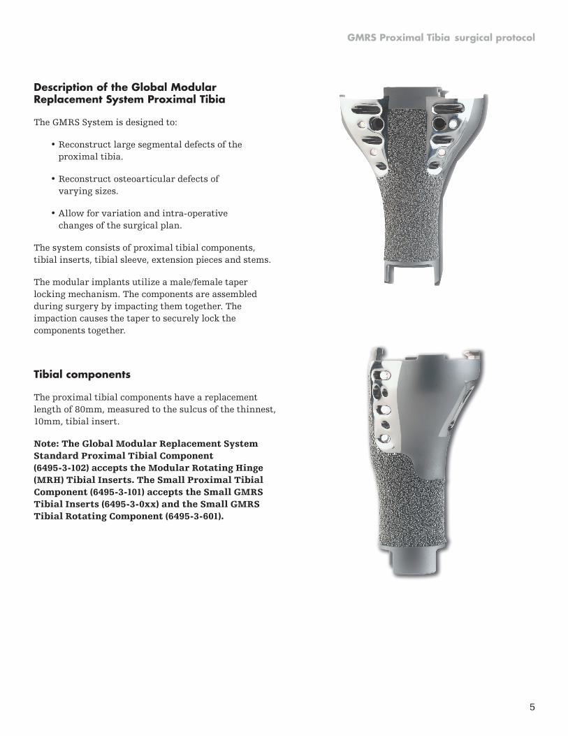
Description of the Global Modular Replacement System Proximal Tibia
The GMRS System is designed to:
• Reconstruct large segmental defects of the proximal tibia .
• Reconstruct osteoarticular defects of varying sizes .
• Allow for variation and intra-operative changes of the surgical plan .
The system consists of proximal tibial components, tibial inserts, tibial sleeve, extension pieces and stems .
The modular implants utilize a male/female taper locking mechanism . The components are assembled during surgery by impacting them together . The impaction causes the taper to securely lock the components together .
Tibial components
The proximal tibial components have a replacement length of 80mm, measured to the sulcus of the thinnest, 10mm, tibial insert .
Note: The Global Modular Replacement System Standard Proximal Tibial Component (6495-3-102) accepts the Modular Rotating Hinge (MRH) Tibial Inserts . The Small Proximal Tibial Component (6495-3-101) accepts the Small GMRS Tibial Inserts (6495-3-0xx) and the Small GMRS Tibial Rotating Component (6495-3-601) .

The GMRS Proximal Tibia accepts the modular cemented stems, available with or without a 40mm extra cortical porous body section . Optional stem centralizers are available for the 10-17mm diameter stems .
Extension Pieces
The Extension Pieces are used to customize the replacement length and are available in 30mm, 40mm, 50mm, 60mm, 70mm, 80mm, 100mm, 120mm, 140mm, 160mm, 180mm, 200mm and 220mm lengths .
MRS cemented stems
MRH femoral components
The MRH femoral components are available in 5 sizes: X-SML, SML, MED, LRG, X-LRG in left and right configurations . These femoral components require a 9mm resection of the distal femur .
6
GMRS Proximal Tibia surgical protocol
Diameter Cemented straight stems Cemented straight stems with bodyØ8mm 6485-3-018 6485-3-008Ø9mm 6485-3-019 6485-3-009Ø10mm 6485-3-010 6485-3-000Ø11mm 6485-3-111 6485-3-011Ø13mm 6485-3-113 6485-3-013Ø15mm 6485-3-115 6485-3-015Ø17mm 6485-3-117 6485-3-017

GMRS Proximal Tibia surgical protocol
7
Indications
The Global Modular Replacement System is intended for use in patients requiring extensive reconstruction of the hip joint and/or knee joint, including knee fusions, necessitated by extensive bone loss due to trauma, failed previous prosthesis and/or tumor resection .
Contraindications
A . As related to bone tumors:
Not all bone tumors may be treated successfully by segmental resection . Any condition that may have already resulted in either local or distant spread of the tumor may be a contraindication . Examples of such conditions include:
• Pathological fracture;
• Overt infection;
• Inopportune placement of biopsy incision; and,
• Rapid disease progression beyond a respectable margin .
Each patient must therefore be individualized and carefully evaluated by appropriate staging techniques prior to consideration of segmental replacement .
B . As related to failed previous prosthesis and trauma:
• Any active or suspected latent infection in or about the operative joint .
• Any mental or neuromuscular disorder which would create an unacceptable risk of prosthesis instability, prosthesis fixation failure, or complication in postoperative care .
• Bone stock compromised by disease, infection, or prior implantation, which cannot provide adequate support and fixation of the prosthesis .
• HA coated stems are contraindicated in situations where bone stock is inadequate to support press fit application .
See package insert for warnings, precautions, adverse effects, information for patients, and other essential product information .
Before using GMRS instrumentation, verify:
• Instruments have been properly disassembled prior to cleaning and sterilization;
• Instruments have been properly assembled post-sterilization;
• Instruments have maintained design integrity; and,
• Proper size configurations are available .
For Instructions for Cleaning, Sterilization, Inspection and Maintenance of Orthopaedic Medical Devices, refer to LSTPI-B .

GMRS Proximal Tibia surgical protocol
8
Measuring resection length
The Proximal Tibial Template may be used as a guide to determine resection location . The template can be positioned using either of two methods .
First, the proximal straight edge, engraved ‘Distal Femoral Cut’, can be positioned 9mm proximal to the distal most aspect of the condyles and determining the resection location from the appropriate slot (Figure 2) .
Second, the profile of the outline of the implant condyles on the template can be aligned with the distal most aspect of the condyles by viewing them through the medial and lateral cut outs in the template (Figure 2 inset) and determining the resection location from the appropriate slot . Resection lengths indicated in the template are based on a 10mm insert and include the tibial bearing component length .
The minimum resection of the tibia is 99mm, which includes 8mm for the tibial bearing component, 80mm from the proximal tibial component with 10mm insert, and a bodiless stem (11mm replacement length) .
Figure 2
Proximal TibialTemplate
9mm
Distal femoral cut
80mmreplacementlength with10mm insert
Distal femoral cut
80mmreplacementlength with10mm insert
Tibia
Nwithout
body
with body N
+40
+50+30
+70
+50
+60
+70
+30
+60
+40
+80
+80
Note: Frame color around each instrument indicates the corresponding GMRS Instrument Tray color .
Instruments without a colored frame are instruments from the MRH or the Duracon TS Instrument Trays .
6496-9-072Proximal Tibial Template
GMRS Tray No: 2
Figure 1
Measurement

GMRS Proximal Tibia surgical protocol
9
Tibial osteotomy
All remaining soft tissue at the level of transection is cleared . The osteotomy, perpendicular to the tibial shaft, is performed after the surrounding tissues and structures have been protected and retracted (Figure 3) .
Surgical tip: Resect the tibia slightly proximal to the marked resection level to allow the facing reamer (see Figure 13 page 15) to plane accurately up to the mark at a 90° angle .
Note: It is extremely important not to distract the extremity following the resection to protect the neurovascular structures . The end of the tibial osteotomy should be kept well padded to avoid injuring the vessels . The length of the resected specimen should be checked and measured again following resection .
Femoral sizing
In addition to pre-operative templating, femoral sizing may be established using the Femoral Sizing Template . The Femoral Sizing Template may be used to evaluate the M/L width of distal femur (Figure 4a) or by evaluating the position of the anterior flange cut with respect to the IM canal (Figure 4b) .
If the two sizing methods differ, the smaller femoral size should be selected assuming that the smaller component will not notch the femur . Figure 4a
M/L sizing indicator
Figure 4b
4
N
Stem location
Figure 3
6481-1-02XFemoral Sizing Template
MRH Instrument Tray H2

Femoral preparation for the Modular Rotating Hinge (MRH) femoral component
Femoral canal preparation
The Intracondylar Starter Drill should be used to create a hole immediately anterior to the insertion of the anterior cruciate ligament . A stem of at least 80mm must be used on the MRH femoral components . IM Reamers, available in diameters 8–23mm, are sequentially advanced into the canal until the tip of the appropriate Depth Gauge reaches the level of the most prominent bony aspect of the distal femur (Figure 5) .
Note: It is extremely important not to distract the extremity following the resection to protect the neurovascular structures . The end of the tibial osteotomy should be kept well padded to avoid injuring the vessels . The length of the resected specimen should be checked and measured again following resection .
Figure 6 gives an example of depth stops marking, and how it relates to preparation of the medullary canal for a given combination of implants . The reamers prepare the canal for a line-to-line fit for the Cobalt Chrome Stems and prepare the canal for a 1/2mm interference fit for the Titanium Fluted Stems.
Surgical tip: In situations where stem diameters of 14mm or less are being used, it is necessary to ream the medullary canal of the distal femur with a 15mm reamer to at least 52mm . This reaming provides the necessary clearance to fully seat the cutting guide instrument and the “stem boss” portion of the stemmed femoral component .
It is strongly recommended that the intramedullary reaming be performed manually to avoid bone perforation and/or fracture .
6266-5-410
T-Handle
IM Reamer Tray R2
6633-9-4XX
IM-Reamer
IM Reamer Tray R2
6481-1-05X
IM-Reamer Depth Gauge
MRH Instrument Tray H2
6838-7-673
Intracondylar Starter Drill
IM Reamer Tray R2
T-Handle
Depth Gauge
Reamer
Figure 5
Stem boss
80mm stem(without offset)
Reamer
Reamer Depth Gauge
MR
H f
emu
r 80
mm
Figure 6
GMRS Proximal Tibia surgical protocol
10

GMRS Proximal Tibia surgical protocol
11
6633-9-428 Resection Guide Tower
Extension Gap Prep . Tray R3
6633-9-48X
Femoral Collar
Extension Gap Prep . Tray R3
Femoral Collar
Resection Guide Tower
Trial Stem
Distal femoral resection
After preparing the medullary canal, the corresponding diameter Trial Stem is selected and attached to the Resection Guide Tower . The appropriate left or right Femoral Collar may be attached to the tower to assist in setting the final depth and rotation of the instrument (Figure 6a) . The assembly is inserted into the canal until the collar contacts the most prominent bony aspect of the distal femur .
Surgical tip: To insert and extract the assembly in and out of the medullary canal, the T-Handle and Impactor/Extractor can be utilized (Figure 6b) .
Figure 6a
Figure 6b
Resection Guide TowerReference mark
T-Handle
Hex Impactor/Extractor
6633-9-430
Femoral Resection Guide
Extension Gap Prep . Tray R3
6838-7-2X0
Alignment Rod
Extension Gap Prep . Tray R3
6633-7-250
Alignment Handle
Extension Gap Prep . Tray R3
6778-6-XXX
Trial Stem
Trial Stem Tray R6
6633-9-404
Impactor/Extractor
Extension Gap Prep . Tray R3
12
GMRS Proximal Tibia surgical protocol
Femoral Resection Guide
N 5mm10mm
N 5mm10mm
Alignment Rod
Augment Handle
N 5mm10mm
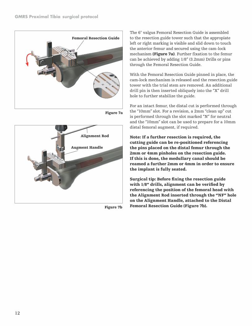
The 6° valgus Femoral Resection Guide is assembled to the resection guide tower such that the appropiate left or right marking is visible and slid down to touch the anterior femur and secured using the cam-lock mechanism (Figure 7a) . Further fixation to the femur can be achieved by adding 1/8” (3 .2mm) Drills or pins through the Femoral Resection Guide .
With the Femoral Resection Guide pinned in place, the cam-lock mechanism is released and the resection guide tower with the trial stem are removed . An additional drill pin is then inserted obliquely into the “X” drill hole to further stabilize the guide .
For an intact femur, the distal cut is performed through the “10mm” slot . For a revision, a 2mm “clean up” cut is performed through the slot marked “N” for neutral and the “10mm” slot can be used to prepare for a 10mm distal femoral augment, if required .
Note: If a further resection is required, the cutting guide can be re-positioned referencing the pins placed on the distal femur through the 2mm or 4mm pinholes on the resection guide . If this is done, the medullary canal should be reamed a further 2mm or 4mm in order to ensure the implant is fully seated .
Surgical tip: Before fixing the resection guide with 1/8” drills, alignment can be verified by referencing the position of the femoral head with the Alignment Rod inserted through the “NF” hole on the Alignment Handle, attached to the Distal Femoral Resection Guide (Figure 7b) .
Figure 7a
Figure 7b

GMRS Proximal Tibia surgical protocol
13
Intramedullary alignment
The appropriate left or right 6° Valgus Stem Adaptor is assembled to the selected size Femoral A/P Chamfer Resection Guide and set to the “N” line on the resection block . The Trial Stem is then attached (Figure 8a) . The assembly is inserted into the canal until the Resection Guide rests against the cut distal femur (Figure 8b) .
If a 10mm distal augment cut has been made for a femur being revised, a magnetic 10mm Resection Guide Spacer may be attached to the Femoral Resection Guide (Figure 8c) .
Figure 8a
Valgus Stem Adaptor Trial Stem
Femoral A/P Chamfer Resection Guide
4
N4
N
Figure 8cFigure 8b
4
N4
N
Resection Guide Spacer
6633-9-46X
Valgus Stem Adaptor
MRH Instrument Tray H2
6481-1-01X
Femoral A/P Chamfer Resection Guide
MRH Instrument Tray H2
6481-1-009
Resection Guide Spacer
MRH Instrument Tray H2
10mm

MRH Instrument Tray H2
6633-8-052
Anterior Reference Indicator
4
N 4
N
Anterior Shim Plate
Anterior Reference Indicator
4
4N
N
Locking knob
Femoral A/P Resection Guide
Figure 9
Femoral sizing and resection
Femoral sizing can be verified using the Anterior Reference Indicator referencing the anterior cortex (Figure 9) .
Correct internal/external rotation of the Femoral A/P Chamfer Resection Guide can be achieved by setting the Guide parallel to the transepicondylar axis . The guide can then be fixed using 1/8” (3.2mm) Drills or pins.
Surgical tip: The tabs on the posterior aspect of the Femoral A/P Chamfer Resection Guide represent the posterior condyles of the Femoral Component .
Figure 10
After making the anterior flange resection, the Anterior Shim Plate can be attached to the Femoral A/P Chamfer Resection Guide to provide stability for the Resection Guide Assembly during the anterior and posterior chamfer resections (Figure 10) .
Surgical tip: A narrow oscillating saw blade of approximately 1/2” (12 .7mm) is recommended for the chamfer cuts .
6633-9-464Anterior Shim Plate
MRH Instrument Tray H2
14
GMRS Proximal Tibia surgical protocol

GMRS Proximal Tibia surgical protocol
15
Figure 5
Trial FemoralComponent
Trial Stem
Femoral Trial positioning
The Trial Femoral Component can be fitted with the appropriate Trial Stem before being placed onto the prepared bone (Figure 11) .
6778-6-XXX
Trial Stem
Trial Stem Tray R6
6481-1-3XX
Trial Femoral Component
MRH Instrument Tray H1
Figure 11

16
GMRS Proximal Tibia surgical protocol
Figure 12
Preparation of the tibia
A flexible guide wire is inserted into the tibial canal. Flexible reamers are utilized to progressively ream the canal to the appropriate diameter . To permit an adequate cement mantle, a stem 2mm smaller than the final reamer diameter should be selected.
Note: The seven stem diameters are 8mm, 9mm, 10mm, 11mm, 13mm, 15mm, and 17mm .
The appropriate Facing Reamer is used to plane the osteotomy site to ensure direct contact and accurate seating of the prosthesis by preparing for the radius at the stem/seat junction (Figure 12) .
Trial assembly
Construct the Trial Tibial Prosthesis by joining the Trial Stem with the Trial Proximal Tibia Component, and Trial Extension Piece, if necessary . The Trial Insert is seated onto the trial proximal tibial component and the Trial Tibial Bearing Component is inserted through the trial insert into the Trial Proximal Tibia Component (Figure 13) .
6486-3-XXX
Trial Stem
GMRS Tray No: 4A
6496-9-2XX
Facing Reamer
GMRS Tray No: 4A GMRS Tray No: 2
6496-3-10X
Trial Proximal Tibial Component
6496-6-0X0
Trial Extension Piece
GMRS Tray No: 2
6496-3-60X
Trial Tibial Bearing Component
GMRS Tray No: 2
6481-3-5XX 6496-3-0XX
Trial Inserts
GMRS Tray No: 2
Facing Reamer
Trial Tibial Bearing Component
Trial Tibial Insert
Trial Proximal TibialComponent
Trial ExtensionPiece
Trial CementedStem
Figure 13
GMRS Proximal Tibia surgical protocol
17
Figure 14
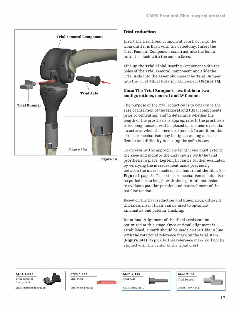
Trial reduction
Insert the trial tibial component construct into the tibia until it is flush with the osteotomy. Insert the Trial Femoral Component construct into the femur until it is flush with the cut surfaces.
Line up the Trial Tibial Bearing Component with the holes of the Trial Femoral Component and slide the Trial Axle into the assembly . Insert the Trial Bumper into the Trial Tibial Rotating Component (Figure 14) .
Note: The Trial Bumper is available in two configurations, neutral and 3º flexion.
The purpose of the trial reduction is to determine the ease of insertion of the femoral and tibial components prior to cementing, and to determine whether the length of the prosthesis is appropriate . If the prosthesis is too long, tension will be placed on the neurovascular structures when the knee is extended . In addition, the extensor mechanism may be tight, causing a loss of flexion and difficulty in closing the soft tissues.
To determine the appropriate length, one must extend the knee and monitor the distal pulse with the trial prosthesis in place . Leg length can be further evaluated by verifying the measurement made previously between the marks made on the femur and the tibia (see Figure 1 page 8) . The extensor mechanism should also be pulled out to length with the leg in full extension to evaluate patellar position and reattachment of the patellar tendon .
Based on the trial reduction and kinematics, different thickness insert trials can be used to optimize kinematics and patellar tracking .
Rotational Alignment of the tibial trials can be optimized at this stage . Once optimal alignment is established, a mark should be made on the tibia in line with the rotational reference mark on the trial stem . (Figure 14a) . Typically, this reference mark will not be aligned with the center of the tibial crest .
Trial Axle
Trial Femoral Component
Trial Bumper
6778-6-XXX
Trial Stem
6496-2-13X
Trial Bumper
GMRS Tray No: 2
6496-2-115
Trial Axle
GMRS Tray No: 2
6481-1-3XX
Trial Femoral Component
MRH Instrument Tray H1 Trial Stem Tray R6
Figure 14a

18
GMRS Proximal Tibia surgical protocol
Cemented Stem
Tibial implant assembly
The Proximal Tibia prosthesis consists of the cemented stem, Extension Piece (when needed based on the length of the reconstruction), the Proximal Tibia replacement, the Tibial Insert and Tibial Sleeve (Figure 15a) . If necessary, it is acceptable to stack two Extension Pieces to construct the necessary length . The instruments used for the assembly of the prosthesis are the Impaction Tube, Impaction Tube Insert, 5-in-1 Impactor, and a Mallet .
Note: Before joining any of the tapers, make sure the male and female components are completely clean and dry .
Insert the appropriate size Impaction Tube Insert (7-11, or 13-17) into the Impaction Tube (Figure 15b) . The selected size stem implant is inserted into the impaction tube assembly . If an Extension Piece is required, it is assembled onto the male taper of the stem, and the male taper of the Extension Piece is impacted by placing the appropriate size hole of the 5-in-1 Impactor over it and hitting with a Mallet (Figure 15c) . The Proximal Tibial Component is then mounted onto the male taper of the Stem or Extension Piece . The 5-in-1 Impactor can be used to impact the assembly by aligning the two holes of the impactor with the two tabs of the Proximal Tibia segment and hitting with a Mallet (Figure 15d) .
Tibial Insert
Tibial Sleeve
Proximal TibialComponent
ExtensionPiece
5-in-1Impactor/Wrench
Mallet
ImpactionTube Insert
ImpactionTube
6496-9-06X
Impaction Tube Insert
GMRS Tray No: 4A
6496-9-053
Impaction Tube
GMRS Tray No: 4A
6496-9-063
5-in-1 Impactor
GMRS Tray No: 3
Figure 15a
Figure 15d
Figure 15b
Figure 15c

GMRS Proximal Tibia surgical protocol
19
MRH Instrument Tray H2
Femoral implant assembly
To attach a CoCr Stem to the implant, hand tighten the stem into the stem boss as far as possible . Attach the All-in-One Wrench to the Torque Wrench, insert the male hex tip of the wrench into the hex recess of the stem and tighten to 120-180 in/lbs (Figure 16a) .
Note: If using a 155mm Titanium Fluted Stem, tighten to 120–180 in/lbs with the Tri-Fluted Section of the All-in-One Wrench (Figure 16b) . Note: Orient the All-in-One Wrench with the long axis of the Torque Wrench . Note: A stem of at least 80mm must be used on the MRH femoral components .
The Distal Femoral Augments are attached by screw fixation to the distal condylar area of the femoral component . The Torque Wrench is attached to the Distal Locking Screw Adaptor via the 3/8” Square Drive Adaptor . A locking torque of 60-80 in/lbs is applied to the screw head in order to lock the Augment and femoral component together (Figure 16c) .
Torque Wrench
All-in-One Wrench
Stem
Femoral Component
6633-8-230
Distal Locking Screw Adaptor
MRH Instrument Tray H2
6633-9-986
Torque Wrench
MRH Instrument Tray H2
8200-0105
All-in-One Wrench
6633-9-989
3/8” Square Drive Adaptor
Figure 16a
Torque Wrench
Distal LockingScrew Adaptor
3/8” Square Drive Adaptor
Distal FemoralAugment
Figure 16b Figure 16c
MRH Instrument Tray H2

20
Femoral Impactor/Extractor
Figure 17
Implantation and orientation of the femoral and tibial prostheses
Surgical tip: If a stem centralizer is not being used, plug the hole in the stem with bone cement . Failure to plug the hole may lead to increased porosity of the cement at the stem tip, where peak stresses occur in the cement and may initiate cracks in the cement at the stem tip .
The prosthesis is then inserted into the tibial canal until the stem seat is flush with the host bone at the osteotomy site and aligned with the mark previously made on the tibia . Excess cement is removed from around the prosthesis .
Surgical bone cement is applied to the cut surfaces of the distal femur and to the inner surfaces and around the boss of the femoral implant construct . To implant the femoral component, the medullary canal is irrigated and dried . The prosthesis is attached to the Femoral Impactor/Extractor (Figure 17) and guided onto the femur and impacted until it is flush with the cut surfaces.
8000-8080
Femoral Impactor/Extractor
Extension Gap Prep . Tray R3
GMRS Proximal Tibia surgical protocol

GMRS Proximal Tibia surgical protocol
21
Figure 18
Final trial articulation with prostheses
With the femoral and tibial prostheses in place, it is possible to use the Trial Axle, the Trial Bumper, the Trial Tibial Rotating Component and the Trial Tibial Insert to verify that the appropriate motion, stability and patellar tracking will be achieved (Figure 18) . With the knee in full extension this also assists in loading the femoral and tibial components while the cement is curing to provide an optimal bond between implant and bone .
Femoral Implant
Trial Bumper
ProximalTibialImplant
Trial Tibial RotatingComponent
Trial Tibial Insert
Trial Axle
Figure 19a
Tibial Sleeve
ProximalTibial Implant

22
GMRS Proximal Tibia surgical protocol
31
Femoral Implant
Femoral Bushings
Axle
Tibial Rotating Component
Tibial Insert
Tibial Sleeve
Proximal Tibial Implant
Bumper
Figure 19e
The Tibial Sleeve is inserted into the Proximal Tibia (Figure 19a) . The appropriate size Tibial Insert is impacted onto the Proximal Tibia . The two bushings are inserted into the femoral component from the centerline of the implant outward as shown (Figure 19b) . The Tibial Rotating Component is inserted into the Proximal Tibia and brought between the bushings (Figure 19c) . The Axle is then introduced as shown (Figure 19e) . A recess or cut-out exists on the Axle to accept the Bumper . By viewing through the bumper hole, verify the recess of the Axle is aligned with the hole . The Bumper is then inserted as shown (Figure 19d) to lock the assembly together . It should be impacted until flush with the Tibial Rotating Component, and has cleared the locking tab .
Surgical tip: The Axle Guider Rod can be threaded into the end of the Axle implant to help guide and align the holes of the bushings with the hole of the TRC during assembly . The Axle Introducer can be used to rotate the Axle to align the recess in the axle with the bumper hole to assemble the bumper .
Note: After the bumper is in place, the axle should not be rotated. It will be in its final position.
Assembly of Rotating Hinge mechanism
The parts needed to assemble the Rotating Hinge mechanism are shown in Figure 19e .
FemoralBushings
Tibial Insert
Figure 19b
6483-9-008
Axle Introducer
6481-1-008
Axle Guider Rod
MRH Instrument Tray H1 MRH Instrument Tray H1
Axle
Locking tab
Bumper hole
Bumper
Figure 19d
Figure 19c
Tibial RotatingComponent

GMRS Proximal Tibia surgical protocol
23
Chisel
Nut
Figure 20a
Appendix - taper disassembly Should it be necessary to disengage an assembled taper joint, a Taper Separator is provided . The correct orientation is in an anterior-to-posterior direction . The implants are designed to withstand the forces generated by the separator in this direction . Placement of the separator wedges against the anti-rotation tabs may damage them, making disengagement difficult. The separator may be used via three different methods .
Method 1
The wedges are initially advanced by hand to bring them in contact with the implant at the joint to be disengaged . The wedges are advanced by turning the nut in a clockwise direction, until resistance is felt (Figure 20a) . The wedges are then further advanced, using the wrench end of the 5-in-1 Impactor provided, until the tapers disengage .
Method 2
The wedges of the separator are advanced until they are sufficiently tight against the taper junction to be separated using the wrench end of the 5-in-1 Impactor . A mallet can then be used to impact the chisel component of the separator . The separator is designed to allow the nut and chisel to travel a small distance when impacted to ease separation .
Method 3
The separator can be disassembled and the chisel component of the assembly can be used by itself to separate a taper junction (Figure 20b) . The chisel is inserted anteriorly at the location to be separated and impacted with a mallet until separation is achieved .
Caution should be taken when disengaging any taper-locked joint . The high forces that hold a taper-locked joint together may result in a sudden and forceful action upon disengagement along the axis of the tapers .
Figure 20b
Chisel
6496-9-054/055/056Taper Separator
GMRS Tray No: 3

24
GMRS Proximal Tibia surgical protocol
Titanium Fluted Cobalt Chrome
Description Diameter 80mm 155mm 80mm 15mmStem 10mm 6478-6-600 6478-6-680 6478-6-395 6478-6-435
Stem 11mm 6478-6-605 6478-6-685 6478-6-396 6478-6-436
Stem 12mm 6478-6-610 6478-6-690 6478-6-397 6478-6-437
Stem 13mm 6478-6-615 6478-6-695 6478-6-398 6478-6-438
Stem 14mm 6478-6-620 6478-6-705 6478-6-399 6478-6-439
Stem 15mm 6478-6-625 6478-6-710 6478-6-400 6478-6-440
Stem 16mm 6478-6-630 6478-6-715 6478-6-405 6478-6-445
Stem 17mm 6478-6-635 6478-6-720 6478-6-410 6478-6-450
Stem 18mm 6478-6-640 6478-6-725 6478-6-415 6478-6-455
Stem 19mm 6478-6-645 6478-6-730 6478-6-420 6478-6-460
Stem 21mm 6478-6-655 6478-6-740 6478-6-425 6478-6-465
Stem 23mm 6478-6-665 6478-6-750 6478-6-430 6478-6-470
Description Size Left Right M/L A/PMRH Femoral Component XS 6481-1-100 6481-1-101 60mm 54mm
MRH Femoral Component Small 6481-1-110 6481-1-111 65mm 55mm
MRH Femoral Component Medium 6481-1-120 6481-1-121 70mm 61mm
MRH Femoral Component Large 6481-1-130 6481-1-131 75mm 64mm
MRH Femoral Component XL 6481-1-140 6481-1-141 80mm 66mm
Description Size Ref #Femoral Distal Block 10mm XS 6481-1-200
Femoral Distal Block 10mm Small 6481-1-210
Femoral Distal Block 10mm Medium 6481-1-220
Femoral Distal Block 10mm Large 6481-1-230
Femoral Distal Block 10mm XL 6481-1-240
Description Size Ref #MRH Axle All Sizes 6481-2-120
MRH Femoral Bushing All Sizes 6481-2-110
Tibial Sleeve All Sizes 6481-2-140
Bumper Insert Neutral 6481-2-130
Bumper Insert 3 Degrees 6481-2-133
Description Size Ref #GMRS Tibial Rotating Component forSmall Proximal Tibia only
Small 6495-3-601
MRH Tibial Rotating Component forStandard Proximal Tibia only
Standard 6481-2-100
Description Thickness Ref #GMRS Tibial Insert for Small Proximal Tibia 10mm 6495-3-010
GMRS Tibial Insert for Small Proximal Tibia 13mm 6495-3-013
GMRS Tibial Insert for Small Proximal Tibia 16mm 6495-3-016
GMRS Tibial Insert for Small Proximal Tibia 20mm 6495-3-020
GMRS Tibial Insert for Small Proximal Tibia 24mm 6495-3-024
Description Thickness Ref # S1/S2MRH Tibial Insert for Standard Proximal Tibia 10mm 6481-3-210
MRH Tibial Insert for Standard Proximal Tibia 13mm 6481-3-213
MRH Tibial Insert for Standard Proximal Tibia 16mm 6481-3-216
MRH Tibial Insert for Standard Proximal Tibia 20mm 6481-3-220
MRH Tibial Insert for Standard Proximal Tibia 24mm 6481-3-224
Implant listing

GMRS Proximal Tibia surgical protocol
25
Description Size Ref # M/L A/PProximal Tibial Component
Small 6495-3-101 52mm 41mm
Proximal Tibial Component
Standard 6495-3-102 65mm 54mm
Description Length Ref #Extension Piece 30mm 6495-6-030
Extension Piece 40mm 6495-6-040
Extension Piece 50mm 6495-6-050
Extension Piece 60mm 6495-6-060
Extension Piece 70mm 6495-6-070
Extension Piece 80mm 6495-6-080
Straight stem
With porous coated Without porous coated
Description Diameter body section body sectionCemented Stem (102mm Length) 8mm 6485-3-008 6485-3-018
Cemented Stem (102mm Length) 9mm 6485-3-009 6485-3-019
Cemented Stem (102mm Length) 10mm 6485-3-000 6485-3-010
Cemented Stem (127mm Length) 11mm 6485-3-011 6485-3-111
Cemented Stem (127mm Length) 13mm 6485-3-013 6485-3-113
Cemented Stem (127mm Length) 15mm 6485-3-015 6485-3-115
Cemented Stem (127mm Length) 17mm 6485-3-017 6485-3-117
Extension Piece length Stem without body Stem with bodyNone 99mm 128mm
30mm 129mm 158mm
40mm 139mm 168mm
50mm 149mm 178mm
60mm 159mm 188mm
70mm 169mm 198mm
80mm 179mm 208mm
Proximal Tibial Component length (including 10mm Tibial Insert) = 80mm
Tibial Rotating Component = 8mm
Stem without body = 11mm
Stem with body = 40mm
Resection length chart

26
GMRS Proximal Tibia surgical protocol
Notes

GMRS Proximal Tibia surgical protocol
27
Notes

This document is intended solely for the use of healthcare professionals .
GMRS Proximal Tibial components are marketed in the United States for use with bone cement .
A surgeon must always rely on his or her own professional clinical judgment when deciding whether to use a particular product when treating a particular patient . Stryker does not dispense medical advice and recommends that surgeons be trained in the use of any particular product before using it in surgery .
The information presented is intended to demonstrate the breadth of Stryker’s product offerings . A surgeon must always refer to the package insert, product label and/or instructions for use before using any Stryker product . The products depicted are CE marked according to the Medical Device Directive 93/42/EEC . Products may not be available in all markets because product availability is subject to the regulatory and/or medical practices in individual markets . Please contact your Stryker representative if you have questions about the availability of Stryker products in your area .
Stryker Corporation or its divisions or other corporate affiliated entities own, use or have applied for the following trademarks or service marks: GMRS, Duracon, Stryker, Stryker Orthopaedics . All other trademarks are trademarks of their respective owners or holders .
GMRS-SP-2_Rev-1_15126 Copyright © 2017 Stryker Printed in USA www .stryker .com
Joint Replacement