gmsh - christophe geuzaine
TRANSCRIPT

Gmsh

Gmsh Reference ManualThe documentation for Gmsh 4.0
A finite element mesh generator with built-in pre- and post-processing facilities
9 December 2018
Christophe GeuzaineJean-Francois Remacle

Copyright c© 1997-2018 Christophe Geuzaine, Jean-Francois Remacle
Permission is granted to make and distribute verbatim copies of this manual provided thecopyright notice and this permission notice are preserved on all copies.

i
Short Contents
Obtaining Gmsh . . . . . . . . . . . . . . . . . . . . . . . . . . . . . . . . . . . . . . . . . . 1
Copying conditions . . . . . . . . . . . . . . . . . . . . . . . . . . . . . . . . . . . . . . . . 31 Overview . . . . . . . . . . . . . . . . . . . . . . . . . . . . . . . . . . . . . . . . . . . . 5
2 How to read this reference manual? . . . . . . . . . . . . . . . . . . . . . . . 93 Running Gmsh on your system . . . . . . . . . . . . . . . . . . . . . . . . . 11
4 General tools . . . . . . . . . . . . . . . . . . . . . . . . . . . . . . . . . . . . . . . . 21
5 Geometry module . . . . . . . . . . . . . . . . . . . . . . . . . . . . . . . . . . . . 35
6 Mesh module . . . . . . . . . . . . . . . . . . . . . . . . . . . . . . . . . . . . . . . . 45
7 Solver module . . . . . . . . . . . . . . . . . . . . . . . . . . . . . . . . . . . . . . . 71
8 Post-processing module . . . . . . . . . . . . . . . . . . . . . . . . . . . . . . . 73
9 File formats . . . . . . . . . . . . . . . . . . . . . . . . . . . . . . . . . . . . . . . . 107
A Tutorial . . . . . . . . . . . . . . . . . . . . . . . . . . . . . . . . . . . . . . . . . . . 127
B Options . . . . . . . . . . . . . . . . . . . . . . . . . . . . . . . . . . . . . . . . . . . 155
C Compiling the source code . . . . . . . . . . . . . . . . . . . . . . . . . . . . 235
D Gmsh API . . . . . . . . . . . . . . . . . . . . . . . . . . . . . . . . . . . . . . . . . 239
E Information for developers . . . . . . . . . . . . . . . . . . . . . . . . . . . . 277
F Frequently asked questions . . . . . . . . . . . . . . . . . . . . . . . . . . . . 279
G Version history . . . . . . . . . . . . . . . . . . . . . . . . . . . . . . . . . . . . . 287
H Copyright and credits . . . . . . . . . . . . . . . . . . . . . . . . . . . . . . . . 303
I License . . . . . . . . . . . . . . . . . . . . . . . . . . . . . . . . . . . . . . . . . . . . 307
Concept index . . . . . . . . . . . . . . . . . . . . . . . . . . . . . . . . . . . . . . . . . . 315Syntax index . . . . . . . . . . . . . . . . . . . . . . . . . . . . . . . . . . . . . . . . . . . 317


iii
Table of Contents
Obtaining Gmsh . . . . . . . . . . . . . . . . . . . . . . . . . . . . . . . . . . . . 1
Copying conditions . . . . . . . . . . . . . . . . . . . . . . . . . . . . . . . . . 3
1 Overview . . . . . . . . . . . . . . . . . . . . . . . . . . . . . . . . . . . . . . . . 51.1 Geometry: geometrical entity definition . . . . . . . . . . . . . . . . . . . . . . . . . 51.2 Mesh: finite element mesh generation . . . . . . . . . . . . . . . . . . . . . . . . . . . 51.3 Solver: external solver interface . . . . . . . . . . . . . . . . . . . . . . . . . . . . . . . . . 61.4 Post-processing: scalar, vector and tensor field visualization . . . . . 61.5 What Gmsh is pretty good at . . . . . . . . . . . . . . . . . . . . . . . . . . . . . . . . . 61.6 . . . and what Gmsh is not so good at . . . . . . . . . . . . . . . . . . . . . . . . . . 71.7 Bug reports . . . . . . . . . . . . . . . . . . . . . . . . . . . . . . . . . . . . . . . . . . . . . . . . . . . . 8
2 How to read this reference manual? . . . . . . . . . . . 92.1 Syntactic rules used in the manual . . . . . . . . . . . . . . . . . . . . . . . . . . . . . . 9
3 Running Gmsh on your system . . . . . . . . . . . . . . 113.1 Interactive mode . . . . . . . . . . . . . . . . . . . . . . . . . . . . . . . . . . . . . . . . . . . . . . 113.2 Non-interactive mode . . . . . . . . . . . . . . . . . . . . . . . . . . . . . . . . . . . . . . . . . 123.3 Command-line options . . . . . . . . . . . . . . . . . . . . . . . . . . . . . . . . . . . . . . . . 123.4 Mouse actions . . . . . . . . . . . . . . . . . . . . . . . . . . . . . . . . . . . . . . . . . . . . . . . . . 163.5 Keyboard shortcuts . . . . . . . . . . . . . . . . . . . . . . . . . . . . . . . . . . . . . . . . . . . 17
4 General tools . . . . . . . . . . . . . . . . . . . . . . . . . . . . . . . . . . 214.1 Comments . . . . . . . . . . . . . . . . . . . . . . . . . . . . . . . . . . . . . . . . . . . . . . . . . . . . 214.2 Expressions . . . . . . . . . . . . . . . . . . . . . . . . . . . . . . . . . . . . . . . . . . . . . . . . . . . 21
4.2.1 Floating point expressions . . . . . . . . . . . . . . . . . . . . . . . . . . . . . . . . 214.2.2 Character expressions . . . . . . . . . . . . . . . . . . . . . . . . . . . . . . . . . . . . 244.2.3 Color expressions . . . . . . . . . . . . . . . . . . . . . . . . . . . . . . . . . . . . . . . . . 25
4.3 Operators . . . . . . . . . . . . . . . . . . . . . . . . . . . . . . . . . . . . . . . . . . . . . . . . . . . . . 254.4 Built-in functions . . . . . . . . . . . . . . . . . . . . . . . . . . . . . . . . . . . . . . . . . . . . . 274.5 User-defined macros . . . . . . . . . . . . . . . . . . . . . . . . . . . . . . . . . . . . . . . . . . . 284.6 Loops and conditionals . . . . . . . . . . . . . . . . . . . . . . . . . . . . . . . . . . . . . . . . 284.7 General commands . . . . . . . . . . . . . . . . . . . . . . . . . . . . . . . . . . . . . . . . . . . . 294.8 General options . . . . . . . . . . . . . . . . . . . . . . . . . . . . . . . . . . . . . . . . . . . . . . . 34
iv Gmsh 4.0
5 Geometry module . . . . . . . . . . . . . . . . . . . . . . . . . . . . . 355.1 Geometry commands . . . . . . . . . . . . . . . . . . . . . . . . . . . . . . . . . . . . . . . . . . 35
5.1.1 Points . . . . . . . . . . . . . . . . . . . . . . . . . . . . . . . . . . . . . . . . . . . . . . . . . . . . 355.1.2 Curves . . . . . . . . . . . . . . . . . . . . . . . . . . . . . . . . . . . . . . . . . . . . . . . . . . . 365.1.3 Surfaces . . . . . . . . . . . . . . . . . . . . . . . . . . . . . . . . . . . . . . . . . . . . . . . . . . 375.1.4 Volumes . . . . . . . . . . . . . . . . . . . . . . . . . . . . . . . . . . . . . . . . . . . . . . . . . 385.1.5 Extrusions . . . . . . . . . . . . . . . . . . . . . . . . . . . . . . . . . . . . . . . . . . . . . . . 395.1.6 Boolean operations . . . . . . . . . . . . . . . . . . . . . . . . . . . . . . . . . . . . . . . 415.1.7 Transformations . . . . . . . . . . . . . . . . . . . . . . . . . . . . . . . . . . . . . . . . . . 425.1.8 Miscellaneous . . . . . . . . . . . . . . . . . . . . . . . . . . . . . . . . . . . . . . . . . . . . 43
5.2 Geometry options . . . . . . . . . . . . . . . . . . . . . . . . . . . . . . . . . . . . . . . . . . . . . 44
6 Mesh module . . . . . . . . . . . . . . . . . . . . . . . . . . . . . . . . . . 456.1 Choosing the right unstructured algorithm . . . . . . . . . . . . . . . . . . . . 456.2 Elementary entities vs. physical groups . . . . . . . . . . . . . . . . . . . . . . . . 466.3 Mesh commands . . . . . . . . . . . . . . . . . . . . . . . . . . . . . . . . . . . . . . . . . . . . . . 46
6.3.1 Specifying mesh element sizes . . . . . . . . . . . . . . . . . . . . . . . . . . . . 476.3.2 Structured grids . . . . . . . . . . . . . . . . . . . . . . . . . . . . . . . . . . . . . . . . . . 636.3.3 Miscellaneous . . . . . . . . . . . . . . . . . . . . . . . . . . . . . . . . . . . . . . . . . . . . 66
6.4 Mesh options . . . . . . . . . . . . . . . . . . . . . . . . . . . . . . . . . . . . . . . . . . . . . . . . . 69
7 Solver module . . . . . . . . . . . . . . . . . . . . . . . . . . . . . . . . . 717.1 Solver options . . . . . . . . . . . . . . . . . . . . . . . . . . . . . . . . . . . . . . . . . . . . . . . . . 71
8 Post-processing module . . . . . . . . . . . . . . . . . . . . . . . 738.1 Post-processing commands . . . . . . . . . . . . . . . . . . . . . . . . . . . . . . . . . . . . 748.2 Post-processing plugins . . . . . . . . . . . . . . . . . . . . . . . . . . . . . . . . . . . . . . . . 788.3 Post-processing options . . . . . . . . . . . . . . . . . . . . . . . . . . . . . . . . . . . . . . 106
9 File formats . . . . . . . . . . . . . . . . . . . . . . . . . . . . . . . . . . . 1079.1 MSH file format (version 4) . . . . . . . . . . . . . . . . . . . . . . . . . . . . . . . . . . 1079.2 Node ordering . . . . . . . . . . . . . . . . . . . . . . . . . . . . . . . . . . . . . . . . . . . . . . . 112
9.2.1 Low order elements . . . . . . . . . . . . . . . . . . . . . . . . . . . . . . . . . . . . . 1129.2.2 High order elements . . . . . . . . . . . . . . . . . . . . . . . . . . . . . . . . . . . . . 114
9.3 Legacy formats . . . . . . . . . . . . . . . . . . . . . . . . . . . . . . . . . . . . . . . . . . . . . . 1159.3.1 MSH file format version 2 . . . . . . . . . . . . . . . . . . . . . . . . . . . . . . . 1159.3.2 MSH file format version 1 . . . . . . . . . . . . . . . . . . . . . . . . . . . . . . . 1209.3.3 POS ASCII file format (Legacy) . . . . . . . . . . . . . . . . . . . . . . . . . 1229.3.4 POS binary file format (Legacy) . . . . . . . . . . . . . . . . . . . . . . . . . 125

v
Appendix A Tutorial . . . . . . . . . . . . . . . . . . . . . . . . . . 127A.1 t1.geo . . . . . . . . . . . . . . . . . . . . . . . . . . . . . . . . . . . . . . . . . . . . . . . . . . . . . . . 127A.2 t2.geo . . . . . . . . . . . . . . . . . . . . . . . . . . . . . . . . . . . . . . . . . . . . . . . . . . . . . . . 129A.3 t3.geo . . . . . . . . . . . . . . . . . . . . . . . . . . . . . . . . . . . . . . . . . . . . . . . . . . . . . . . 131A.4 t4.geo . . . . . . . . . . . . . . . . . . . . . . . . . . . . . . . . . . . . . . . . . . . . . . . . . . . . . . . 133A.5 t5.geo . . . . . . . . . . . . . . . . . . . . . . . . . . . . . . . . . . . . . . . . . . . . . . . . . . . . . . . 135A.6 t6.geo . . . . . . . . . . . . . . . . . . . . . . . . . . . . . . . . . . . . . . . . . . . . . . . . . . . . . . . 139A.7 t7.geo . . . . . . . . . . . . . . . . . . . . . . . . . . . . . . . . . . . . . . . . . . . . . . . . . . . . . . . 140A.8 t8.geo . . . . . . . . . . . . . . . . . . . . . . . . . . . . . . . . . . . . . . . . . . . . . . . . . . . . . . . 141A.9 t9.geo . . . . . . . . . . . . . . . . . . . . . . . . . . . . . . . . . . . . . . . . . . . . . . . . . . . . . . . 144A.10 t10.geo . . . . . . . . . . . . . . . . . . . . . . . . . . . . . . . . . . . . . . . . . . . . . . . . . . . . . 146A.11 t11.geo . . . . . . . . . . . . . . . . . . . . . . . . . . . . . . . . . . . . . . . . . . . . . . . . . . . . . 147A.12 t12.geo . . . . . . . . . . . . . . . . . . . . . . . . . . . . . . . . . . . . . . . . . . . . . . . . . . . . . 148A.13 t13.geo . . . . . . . . . . . . . . . . . . . . . . . . . . . . . . . . . . . . . . . . . . . . . . . . . . . . . 149A.14 t14.geo . . . . . . . . . . . . . . . . . . . . . . . . . . . . . . . . . . . . . . . . . . . . . . . . . . . . . 150A.15 t15.geo . . . . . . . . . . . . . . . . . . . . . . . . . . . . . . . . . . . . . . . . . . . . . . . . . . . . . 152A.16 t16.geo . . . . . . . . . . . . . . . . . . . . . . . . . . . . . . . . . . . . . . . . . . . . . . . . . . . . . 153
Appendix B Options . . . . . . . . . . . . . . . . . . . . . . . . . . 155B.1 General options list . . . . . . . . . . . . . . . . . . . . . . . . . . . . . . . . . . . . . . . . . . 155B.2 Geometry options list . . . . . . . . . . . . . . . . . . . . . . . . . . . . . . . . . . . . . . . . 184B.3 Mesh options list . . . . . . . . . . . . . . . . . . . . . . . . . . . . . . . . . . . . . . . . . . . . 192B.4 Solver options list . . . . . . . . . . . . . . . . . . . . . . . . . . . . . . . . . . . . . . . . . . . 209B.5 Post-processing options list . . . . . . . . . . . . . . . . . . . . . . . . . . . . . . . . . . 215
Appendix C Compiling the source code . . . . . 235
Appendix D Gmsh API . . . . . . . . . . . . . . . . . . . . . . . 239
Appendix E Information for developers . . . . . 277E.1 Source code structure . . . . . . . . . . . . . . . . . . . . . . . . . . . . . . . . . . . . . . . . 277E.2 Coding style . . . . . . . . . . . . . . . . . . . . . . . . . . . . . . . . . . . . . . . . . . . . . . . . . 277E.3 Adding a new option . . . . . . . . . . . . . . . . . . . . . . . . . . . . . . . . . . . . . . . . 278
Appendix F Frequently asked questions . . . . . 279F.1 The basics . . . . . . . . . . . . . . . . . . . . . . . . . . . . . . . . . . . . . . . . . . . . . . . . . . . 279F.2 Installation problems . . . . . . . . . . . . . . . . . . . . . . . . . . . . . . . . . . . . . . . . 279F.3 General questions . . . . . . . . . . . . . . . . . . . . . . . . . . . . . . . . . . . . . . . . . . . . 280F.4 Geometry module . . . . . . . . . . . . . . . . . . . . . . . . . . . . . . . . . . . . . . . . . . . 280F.5 Mesh module . . . . . . . . . . . . . . . . . . . . . . . . . . . . . . . . . . . . . . . . . . . . . . . . 281F.6 Solver module . . . . . . . . . . . . . . . . . . . . . . . . . . . . . . . . . . . . . . . . . . . . . . . 283F.7 Post-processing module . . . . . . . . . . . . . . . . . . . . . . . . . . . . . . . . . . . . . . 284
Appendix G Version history . . . . . . . . . . . . . . . . . . 287

vi Gmsh 4.0
Appendix H Copyright and credits . . . . . . . . . . . 303
Appendix I License . . . . . . . . . . . . . . . . . . . . . . . . . . . 307
Concept index . . . . . . . . . . . . . . . . . . . . . . . . . . . . . . . . . . . . 315
Syntax index . . . . . . . . . . . . . . . . . . . . . . . . . . . . . . . . . . . . . 317

Obtaining Gmsh 1
Obtaining Gmsh
The source code and various pre-compiled versions of Gmsh (for Windows, Mac and Unix)can be downloaded from http://gmsh.info. Gmsh is also directly available in pre-packagedform in various Linux and BSD distributions (Debian, Ubuntu, FreeBSD, ...).
If you use Gmsh, we would appreciate that you mention it in your work by citing thefollowing paper: “C. Geuzaine and J.-F. Remacle, Gmsh: a three-dimensional finite elementmesh generator with built-in pre- and post-processing facilities. International Journal forNumerical Methods in Engineering, Volume 79, Issue 11, pages 1309-1331, 2009”. A preprintof that paper as well as other references and the latest news about Gmsh development areavailable on http://gmsh.info.


Copying conditions 3
Copying conditions
Gmsh is “free software”; this means that everyone is free to use it and to redistribute it ona free basis. Gmsh is not in the public domain; it is copyrighted and there are restrictionson its distribution, but these restrictions are designed to permit everything that a goodcooperating citizen would want to do. What is not allowed is to try to prevent others fromfurther sharing any version of Gmsh that they might get from you.
Specifically, we want to make sure that you have the right to give away copies of Gmsh,that you receive source code or else can get it if you want it, that you can change Gmsh oruse pieces of Gmsh in new free programs, and that you know you can do these things.
To make sure that everyone has such rights, we have to forbid you to deprive anyone else ofthese rights. For example, if you distribute copies of Gmsh, you must give the recipients allthe rights that you have. You must make sure that they, too, receive or can get the sourcecode. And you must tell them their rights.
Also, for our own protection, we must make certain that everyone finds out that there isno warranty for Gmsh. If Gmsh is modified by someone else and passed on, we want theirrecipients to know that what they have is not what we distributed, so that any problemsintroduced by others will not reflect on our reputation.
The precise conditions of the license for Gmsh are found in the General PublicLicense that accompanies the source code (see Appendix I [License], page 307).Further information about this license is available from the GNU Project webpagehttp://www.gnu.org/copyleft/gpl-faq.html. Detailed copyright information can befound in Appendix H [Copyright and credits], page 303.
If you want to integrate parts of Gmsh into a closed-source software, or want to sell amodified closed-source version of Gmsh, you will need to obtain a different license. Pleasecontact us directly for more information.


Chapter 1: Overview 5
1 Overview
Gmsh is a three-dimensional finite element grid generator with a build-in CAD engine andpost-processor. Its design goal is to provide a fast, light and user-friendly meshing tool withparametric input and advanced visualization capabilities.
Gmsh is built around four modules: geometry, mesh, solver and post-processing. All ge-ometrical, mesh, solver and post-processing instructions are prescribed either interactivelyusing the graphical user interface (GUI) or in text files using Gmsh’s own scripting lan-guage. Interactive actions generate language bits in the input files, and vice versa. Thismakes it possible to automate all treatments, using loops, conditionals and external systemcalls. A programming API is also available, for integrating Gmsh as a library in your ownC++, C, Python or Julia code: see Appendix D [Gmsh API], page 239. A brief descriptionof the four modules is given hereafter.
1.1 Geometry: geometrical entity definition
Gmsh uses a boundary representation (“BRep”) to describe geometries. Models are cre-ated in a bottom-up flow by successively defining points, oriented curves (line segments,circles, ellipses, splines, . . . ), oriented surfaces (plane surfaces, surfaces, triangulated sur-faces, . . . ) and volumes. Groups of geometrical entities (called “physical groups”) can alsobe defined, based on these elementary geometric entities. Gmsh’s scripting language allowsall geometrical entities to be fully parametrized.
1.2 Mesh: finite element mesh generation
A finite element mesh is a tessellation of a given subset of the three-dimensional spaceby elementary geometrical elements of various shapes (in Gmsh’s case: lines, triangles,quadrangles, tetrahedra, prisms, hexahedra and pyramids), arranged in such a way that iftwo of them intersect, they do so along a face, an edge or a node, and never otherwise.All the finite element meshes produced by Gmsh are considered as “unstructured”, evenif they were generated in a “structured” way (e.g., by extrusion). This implies that theelementary geometrical elements are defined only by an ordered list of their nodes but thatno predefined order relation is assumed between any two elements.
The mesh generation is performed in the same bottom-up flow as the geometry creation:curves are discretized first; the mesh of the curves is then used to mesh the surfaces; thenthe mesh of the surfaces is used to mesh the volumes. In this process, the mesh of anentity is only constrained by the mesh of its boundary. For example, in three dimensions,the triangles discretizing a surface will be forced to be faces of tetrahedra in the final 3Dmesh only if the surface is part of the boundary of a volume; the line elements discretizinga curve will be forced to be edges of tetrahedra in the final 3D mesh only if the curve ispart of the boundary of a surface, itself part of the boundary of a volume; a single nodediscretizing a point in the middle of a volume will be forced to be a node of one of thetetrahedra in the final 3D mesh only if this point is connected to a curve, itself part ofthe boundary of a surface, itself part of the boundary of a volume. This automaticallyassures the conformity of the mesh when, for example, two surfaces share a common curve.But this also implies that the discretization of an “isolated” (n-1)-th dimensional entityinside an n-th dimensional entity does not constrain the n-th dimensional mesh—unless
6 Gmsh 4.0
it is explicitly told to do so (see Section 6.3.3 [Miscellaneous mesh commands], page 66).Every meshing step is constrained by a “size field” (sometimes called “characteristic lengthfield”), which prescribes the desired size of the elements in the mesh. This size field can beuniform, specified by values associated with points in the geometry, or defined by general“fields” (for example related to the distance to some boundary, to a arbitrary scalar fielddefined on another mesh, etc.).
For each meshing step, all structured mesh directives are executed first, and serve as addi-tional constraints for the unstructured parts1.
1.3 Solver: external solver interface
External solvers can be interfaced with Gmsh through Unix or TCP/IP sockets, whichpermits to modify solver parameters, launch external computations and process the resultsdirectly from within Gmsh’s post-processing module. The default solver interfaced withGmsh is GetDP (http://getdp.info). Examples on how to interface other solvers areavailable in the source distribution (in the utils/solvers directory).
1.4 Post-processing: scalar, vector and tensor fieldvisualization
Gmsh can load and manipulate multiple post-processing scalar, vector or tensor maps alongwith the geometry and the mesh. Scalar fields are represented by iso-value curves/surfaces orcolor maps, while vector fields are represented by three-dimensional arrows or displacementmaps. Post-processing functions include section computation, offset, elevation, boundaryand component extraction, color map and range modification, animation, vector graphicoutput, etc. All the post-processing options can be accessed either interactively or throughthe input script files. Scripting permits to automate all post-processing operations, as forexample to create animations. User-defined operations can also be performed on post-processing views through dynamically loadable plugins.
1.5 What Gmsh is pretty good at . . .
Here is a tentative list of what Gmsh does best:
• quickly describe simple and/or “repetitive” geometries, thanks to user-defined macros,loops, conditionals and includes (see Section 4.5 [User-defined macros], page 28,Section 4.6 [Loops and conditionals], page 28, and Section 4.7 [General commands],page 29);
• parametrize these geometries. Gmsh’s scripting language enables all commands andcommand arguments to depend on previous calculations (see Section 4.2 [Expressions],page 21, and Section 5.1 [Geometry commands], page 35). Using the OpenCASCADEgeometry kernel, Gmsh gives access to all usual constructive solid geometry operations;
• generate 1D, 2D and 3D simplicial (i.e., using line segments, triangles and tetrahedra)finite element meshes for CAD models in their native format (without translations)when linked with the appropriate CAD kernel (see Chapter 6 [Mesh module], page 45);
1 Note that mixing structured volume grids with unstructured volume grids generated with the default 3DDelaunay algorithm can result, in certain cases, to non-conform surface meshes on their shared boundary.If this happens, you may consider using the frontal algorithm for the unstructured part.

Chapter 1: Overview 7
• specify target element sizes accurately. Gmsh provides several mechanisms to controlthe size of the elements in the final mesh: through interpolation from sizes specified atgeometry points or using flexible mesh size fields (see Section 6.3 [Mesh commands],page 46);
• create simple extruded geometries and meshes (see Section 5.1 [Geometry commands],page 35, and Section 6.3 [Mesh commands], page 46);
• interact with external solvers through a simple client-server architecture (see Chapter 7[Solver module], page 71);
• visualize and export computational results in a great variety of ways. Gmsh can displayscalar, vector and tensor datasets, perform various operations on the resulting post-processing views (see Chapter 8 [Post-processing module], page 73), can export plotsin many different formats (see Section B.1 [General options list], page 155), and cangenerate complex animations (see Chapter 4 [General tools], page 21, and Section A.8[t8.geo], page 141);
• run on low end machines and/or machines with no graphical interface. Gmsh canbe compiled with or without the GUI (see Appendix C [Compiling the source code],page 235), and all versions can be used either interactively or directly from the com-mand line (see Chapter 3 [Running Gmsh on your system], page 11);
• configure your preferred options. Gmsh has a large number of configuration optionsthat can be set interactively using the GUI, scattered inside command files, changed onthe fly in scripts, set in per-user configuration files, or specified on the command-line(see Chapter 3 [Running Gmsh on your system], page 11 and Appendix B [Options],page 155);
• and do all the above on various platforms (Windows, Mac and Unix), for free (see[Copying conditions], page 3), using simple script files and/or a small but powerfulGUI.
1.6 . . . and what Gmsh is not so good at
Here are some known weaknesses of Gmsh:
• Gmsh is not a multi-bloc mesh generator: all meshes produced by Gmsh are conformingin the sense of finite element meshes;
• Gmsh’s user interface is only exposing a limited number of the available features, andmany aspects of the interface could be enhanced (especially manipulators).
• Gmsh’s scripting language is quite limited, providing only very crude loop controls anduser-defined macros, with no local variables. For more complex workflows, or for inte-grating Gmsh as a library directly in other software tools, an application programminginterface is available (see Appendix D [Gmsh API], page 239). This allows to directlyaccess Gmsh features from C++, C, Python or Julia. The C interface makes it relativelyeasy to build interfaces to additional languages (e.g. Javascript, Java or Go).
If you have the skills and some free time, feel free to join the project: we gladly accept anycode contributions (see Appendix E [Information for developers], page 277) to remedy theaforementioned (and all other) shortcomings!

8 Gmsh 4.0
1.7 Bug reports
If you think you have found a bug in Gmsh, please file an issue on https://gitlab.onelab.info/gmsh/gmsh/issues.Please provided as precise a description of the problem as you can, including sample inputfiles that produce the bug. Don’t forget to mention both the version of Gmsh and theversion of your operation system (see Section 3.3 [Command-line options], page 12 to seehow to get this information).
See Appendix F [Frequently asked questions], page 279, and the bug tracking system to seewhich problems we already know about.

Chapter 2: How to read this reference manual? 9
2 How to read this reference manual?
Gmsh can be used at three levels:
1. as a stand-alone graphical program, driven by an interactive graphical user interface(GUI);
2. as a stand-alone script-driven program;
3. as a library.
You can skip most of this reference manual if you only want to use Gmsh at the firstlevel (i.e., interactively with the GUI). Just read the next chapter (see Chapter 3 [Run-ning Gmsh on your system], page 11) to learn how to launch Gmsh on your system, thengo experiment with the GUI and the tutorial files (see Appendix A [Tutorial], page 127)provided in the distribution. Screencasts that show how to use the GUI are available here:http://gmsh.info/screencasts/.
The aim of the reference manual is to explain everything you need to use Gmsh at thesecond level, i.e., using the built-in scripting language. A Gmsh script file is an ASCIItext file that contains instructions in Gmsh’s built-in scripting language. Such a file isinterpreted by Gmsh’s parser, and can be given any extension (or no extension at all). Byconvention, Gmsh uses the ‘.geo’ extension for geometry scripts, and the ‘.pos’ extensionfor parsed post-processing datasets. Once you master the tutorial (read the source files:they are heavily commented!), start reading chapter Chapter 4 [General tools], page 21,then proceed with the next four chapters, which detail the syntax of the geometry, mesh,solver and post-processing scripting commands. You will see that most of the interactiveactions in the GUI have a direct equivalent in the scripting language. If you want to useGmsh as a pre- or post-processor for your own software, you will also want to learn about thenon-scripting input/output files that Gmsh can read/write. In addition to Gmsh’s native“MSH” file format (see Chapter 9 [File formats], page 107), Gmsh can read/write manystandard mesh files, depending on how it was built: check the ‘File->Export’ menu for alist of available formats.
Finally, to use Gmsh at the third level (i.e., to link the Gmsh library with your own code),you will need to learn the Gmsh Application Programming Interface (API). This API isavailable in C++, C, Python and Julia: see Appendix D [Gmsh API], page 239 for moreinformation.
2.1 Syntactic rules used in the manual
Here are the rules we tried to follow when writing this reference manual. Note that meta-syntactic variable definitions stay valid throughout the manual (and not only in the sectionswhere the definitions appear).
1. Keywords and literal symbols are printed like this.
2. Metasyntactic variables (i.e., text bits that are not part of the syntax, but stand forother text bits) are printed like this.
3. A colon (:) after a metasyntactic variable separates the variable from its definition.
4. Optional rules are enclosed in < > pairs.
5. Multiple choices are separated by |.
6. Three dots (. . . ) indicate a possible (multiple) repetition of the preceding rule.


Chapter 3: Running Gmsh on your system 11
3 Running Gmsh on your system
3.1 Interactive mode
To launch Gmsh in interactive mode, just double-click on the Gmsh icon, or type
> gmsh
at your shell prompt in a terminal. This will open the main Gmsh window, with a tree-likemenu on the left, a graphic area on the right, and a status bar at the bottom. (You candetach the tree menu using ‘Window->Attach/Detach Menu’.)
To open the first tutorial file (see Appendix A [Tutorial], page 127), select the ‘File->Open’menu, and choose t1.geo. When using a terminal, you can specify the file name directly onthe command line, i.e.:
> gmsh t1.geo
To perform the mesh generation, go to the mesh module (by selecting ‘Mesh’ in the tree)and choose the dimension (‘1D’ will mesh all the curves; ‘2D’ will mesh all the surfaces—aswell as all the curves if ‘1D’ was not called before; ‘3D’ will mesh all the volumes—and allthe surfaces if ‘2D’ was not called before). To save the resulting mesh in the current meshformat click on ‘Save’, or select the appropriate format and file name with the ‘File->Export’menu. The default mesh file name is based on the name of the current active model, withan appended extension depending on the mesh format1.
To create a new geometry or to modify an existing geometry, select ’Geometry’ in the tree.For example, to create a spline, select ‘Elementary’, ‘Add’, ‘New’ and ‘Spline’. You willthen be asked to select a list of points, and to type e to finish the selection (or q to abort it).Once the interactive command is completed, a text string is automatically added at the endof the current script file. You can edit the script file by hand at any time by pressing the‘Edit’ button in the ‘Geometry’ menu and then reloading the model by pressing ‘Reload’.For example, it is often faster to define variables and points directly in the script file, andthen use the GUI to define the curves, the surfaces and the volumes interactively.
Several files can be loaded simultaneously in Gmsh. When specified on the command line,the first one defines the active model and the others are ‘merged’ into this model. You canmerge such files with the ‘File->Merge’ menu. For example, to merge the post-processingviews contained in the files view1.pos and view5.msh together with the geometry of the firsttutorial Section A.1 [t1.geo], page 127, you can type the following command:
> gmsh t1.geo view1.pos view5.msh
In the Post-Processing module (select ‘Post-Processing’ in the tree), three items will appear,respectively labeled ‘A scalar map’, ‘Nodal scalar map’ and ‘Element 1 vector’. In thisexample the views contain several time steps: you can loop through them with the small“remote-control” icons in the status bar. A mouse click on the view name will toggle thevisibility of the selected view, while a click on the arrow button on the right will provideaccess to the view’s options.
1 Nearly all the interactive commands have keyboard shortcuts: see Section 3.5 [Keyboard shortcuts], page 17,or select ‘Help->Keyboard and Mouse Usage’ in the menu. For example, to quickly save a mesh, you canpress Ctrl+Shift+s.

12 Gmsh 4.0
Note that all the options specified interactively can also be directly specified in the scriptfiles. You can save the current options of the current active model with the ‘File->SaveModel Options’. This will create a new option file with the same filename as the activemodel, but with an extra ‘.opt’ extension added. The next time you open this model, theassociated options will be automatically loaded, too. To save the current options as yourdefault preferences for all future Gmsh sessions, use the ‘File->Save Options As Default’menu instead. Finally, you can also save the current options in an arbitrary file by choosingthe ‘Gmsh options’ format in ‘File->Export’.
For more information about available options (and how to reset them to their default values),see Appendix B [Options], page 155. A full list of options with their current values is alsoavailable in the ‘Help->Current Options’ menu.
3.2 Non-interactive mode
Gmsh can be run non-interactively in ‘batch’ mode, without GUI2. For example, to meshthe first tutorial in batch mode, just type:
> gmsh t1.geo -2
To mesh the same example, but with the background mesh available in the file bgmesh.pos,type:
> gmsh t1.geo -2 -bgm bgmesh.pos
For the list of all command-line options, see Section 3.3 [Command-line options], page 12.In particular, any complicated workflow can be written in a .geo file, and this file can beexecuted as a script using
> gmsh script.geo -
The script can contain e.g. meshing commands, like Mesh 3;.
3.3 Command-line options
Geometry options:
-0 Output model, then exit
-tol float
Set geometrical tolerance
-match Match geometries and meshes
Mesh options:
-1, -2, -3
Perform 1D, 2D or 3D mesh generation, then exit
-save Save mesh, then exit
-o file Specify output file name
2 If you compile Gmsh without the GUI (see Appendix C [Compiling the source code], page 235), this is theonly mode you have access to.

Chapter 3: Running Gmsh on your system 13
-format string
Select output mesh format (auto, msh1, msh2, msh3, msh4, msh, unv, vtk, wrl,mail, stl, p3d, mesh, bdf, cgns, med, diff, ir3, inp, ply2, celum, su2, x3d, dat,neu, m, key)
-bin Create binary files when possible
-refine Perform uniform mesh refinement, then exit
-barycentric_refine
Perform barycentric mesh refinement, then exit
-reclassify
Reclassify mesh, then exit
-part int Partition after batch mesh generation
-part_weight tri|quad|tet|hex|pri|pyr|trih int
Weight of a triangle/quad/etc. during partitioning
-part_split
Save mesh partitions in separate files
-part_[no_]topo
Create the partition topology
-part_[no_]ghosts
Create ghost cells
-part_[no_]physicals
Create physical groups for partitions
-part_topo_pro
Save the partition topology .pro file
-preserve_numbering_msh2
Preserve element numbering in MSH2 format
-save_all
Save all elements (discard physical group definitions)
-save_parametric
Save nodes with their parametric coordinates
-save_topology
Save model topology
-algo string
Select mesh algorithm (meshadapt, del2d, front2d, delquad, del3d, front3d,mmg3d, pack, hxt)
-smooth int
Set number of mesh smoothing steps
-order int
Set mesh order (1, ..., 5)

14 Gmsh 4.0
-optimize[_netgen]
Optimize quality of tetrahedral elements
-optimize_threshold
Optimize tetrahedral elements that have a quality less than a threshold
-optimize_ho
Optimize high order meshes
-ho_[min,max,nlayers]
High-order optimization parameters
-clscale float
Set global mesh element size scaling factor
-clmin float
Set minimum mesh element size
-clmax float
Set maximum mesh element size
-aniso_max float
Set maximum anisotropy (for bamg)
-smooth_ratio float
Set smoothing ration between mesh sizes at nodes of a same edge (for bamg)
-clcurv Automatically compute element sizes from curvatures
-epslc1d Set accuracy of evaluation of mesh size field for 1D mesh
-swapangle
Set the threshold angle (in degree) between two adjacent faces below which aswap is allowed
-rand float
Set random perturbation factor
-bgm file Load background mesh from file
-check Perform various consistency checks on mesh
-ignore_periocity
Ignore periodic boundaries
Post-processing options:
-link int Select link mode between views (0, 1, 2, 3, 4)
-combine Combine views having identical names into multi-time-step views
Solver options:
-listen Always listen to incoming connection requests
-minterpreter string
Name of Octave interpreter
-pyinterpreter string
Name of Python interpreter

Chapter 3: Running Gmsh on your system 15
-run Run ONELAB solver(s)
Display options:
-n Hide all meshes and post-processing views on startup
-nodb Disable double buffering
-numsubedges
Set num of subdivisions for high order element display
-fontsize int
Specify the font size for the GUI
-theme string
Specify FLTK GUI theme
-display string
Specify display
-camera Use camera mode view;
-stereo OpenGL quad-buffered stereo rendering (requires special graphics card)
-gamepad Use gamepad controller if available
Other options:
-, -parse_and_exit
Parse input files, then exit
-new Create new model before merge next file
-merge Merge next files
-open Open next files
-a, -g, -m, -s, -p
Start in automatic, geometry, mesh, solver or post-processing mode
-pid Print process id on stdout
-watch pattern
Pattern of files to merge as they become available
-bg file Load background (image or PDF) file
-v int Set verbosity level
-nopopup Don’t popup dialog windows in scripts
-string "string"
Parse command string at startup
-setnumber name value
Set constant or option number name=value
-setstring name value
Set constant or option string name=value

16 Gmsh 4.0
-option file
Parse option file at startup
-convert files
Convert files into latest binary formats, then exit
-nt int Set number of threads
-cpu Report CPU times for all operations
-version Show version number
-info Show detailed version information
-help Show command line usage
-help_options
Show all options
3.4 Mouse actions
Move - Highlight the entity under the mouse pointer and display its properties
- Resize a lasso zoom or a lasso (un)selection
Left button
- Rotate
- Select an entity
- Accept a lasso zoom or a lasso selection
Ctrl+Left button
Start a lasso zoom or a lasso (un)selection
Middle button
- Zoom
- Unselect an entity
- Accept a lasso zoom or a lasso unselection
Ctrl+Middle button
Orthogonalize display
Right button
- Pan
- Cancel a lasso zoom or a lasso (un)selection
- Pop-up menu on post-processing view button
Ctrl+Right button
Reset to default viewpoint
For a 2 button mouse, Middle button = Shift+Left button.
For a 1 button mouse, Middle button = Shift+Left button, Right button = Alt+Left button.
Chapter 3: Running Gmsh on your system 17
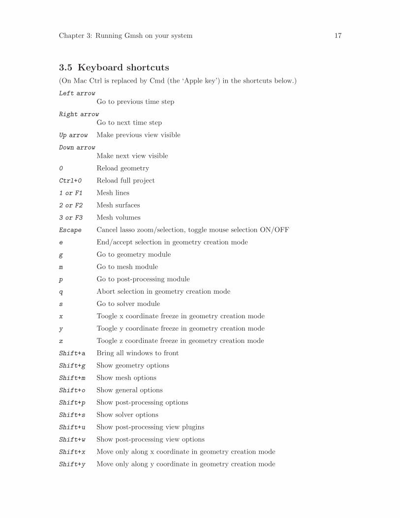
3.5 Keyboard shortcuts
(On Mac Ctrl is replaced by Cmd (the ‘Apple key’) in the shortcuts below.)
Left arrow
Go to previous time step
Right arrow
Go to next time step
Up arrow Make previous view visible
Down arrow
Make next view visible
0 Reload geometry
Ctrl+0 Reload full project
1 or F1 Mesh lines
2 or F2 Mesh surfaces
3 or F3 Mesh volumes
Escape Cancel lasso zoom/selection, toggle mouse selection ON/OFF
e End/accept selection in geometry creation mode
g Go to geometry module
m Go to mesh module
p Go to post-processing module
q Abort selection in geometry creation mode
s Go to solver module
x Toogle x coordinate freeze in geometry creation mode
y Toogle y coordinate freeze in geometry creation mode
z Toogle z coordinate freeze in geometry creation mode
Shift+a Bring all windows to front
Shift+g Show geometry options
Shift+m Show mesh options
Shift+o Show general options
Shift+p Show post-processing options
Shift+s Show solver options
Shift+u Show post-processing view plugins
Shift+w Show post-processing view options
Shift+x Move only along x coordinate in geometry creation mode
Shift+y Move only along y coordinate in geometry creation mode
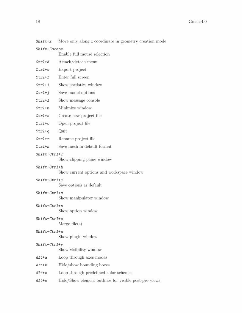
18 Gmsh 4.0
Shift+z Move only along z coordinate in geometry creation mode
Shift+Escape
Enable full mouse selection
Ctrl+d Attach/detach menu
Ctrl+e Export project
Ctrl+f Enter full screen
Ctrl+i Show statistics window
Ctrl+j Save model options
Ctrl+l Show message console
Ctrl+m Minimize window
Ctrl+n Create new project file
Ctrl+o Open project file
Ctrl+q Quit
Ctrl+r Rename project file
Ctrl+s Save mesh in default format
Shift+Ctrl+c
Show clipping plane window
Shift+Ctrl+h
Show current options and workspace window
Shift+Ctrl+j
Save options as default
Shift+Ctrl+m
Show manipulator window
Shift+Ctrl+n
Show option window
Shift+Ctrl+o
Merge file(s)
Shift+Ctrl+u
Show plugin window
Shift+Ctrl+v
Show visibility window
Alt+a Loop through axes modes
Alt+b Hide/show bounding boxes
Alt+c Loop through predefined color schemes
Alt+e Hide/Show element outlines for visible post-pro views

Chapter 3: Running Gmsh on your system 19
Alt+f Change redraw mode (fast/full)
Alt+h Hide/show all post-processing views
Alt+i Hide/show all post-processing view scales
Alt+l Hide/show geometry lines
Alt+m Toggle visibility of all mesh entities
Alt+n Hide/show all post-processing view annotations
Alt+o Change projection mode (orthographic/perspective)
Alt+p Hide/show geometry points
Alt+r Loop through range modes for visible post-pro views
Alt+s Hide/show geometry surfaces
Alt+t Loop through interval modes for visible post-pro views
Alt+v Hide/show geometry volumes
Alt+w Enable/disable all lighting
Alt+x Set X view
Alt+y Set Y view
Alt+z Set Z view
Alt+Shift+a
Hide/show small axes
Alt+Shift+b
Hide/show mesh volume faces
Alt+Shift+c
Loop through predefined colormaps
Alt+Shift+d
Hide/show mesh surface faces
Alt+Shift+l
Hide/show mesh lines
Alt+Shift+p
Hide/show mesh points
Alt+Shift+s
Hide/show mesh surface edges
Alt+Shift+t
Same as Alt+t, but with numeric mode included
Alt+Shift+v
Hide/show mesh volume edges
Alt+Shift+x
Set -X view

20 Gmsh 4.0
Alt+Shift+y
Set -Y view
Alt+Shift+z
Set -Z view

Chapter 4: General tools 21
4 General tools
This chapter describes the general commands and options that can be used in Gmsh’s scriptfiles. By “general”, we mean “not specifically related to one of the geometry, mesh, solveror post-processing modules”. Commands peculiar to these modules will be introduced inChapter 5 [Geometry module], page 35, Chapter 6 [Mesh module], page 45, Chapter 7[Solver module], page 71, and Chapter 8 [Post-processing module], page 73, respectively.
4.1 Comments
Gmsh script files support both C and C++ style comments:
1. any text comprised between /* and */ pairs is ignored;
2. the rest of a line after a double slash // is ignored.
These commands won’t have the described effects inside double quotes or inside keywords.Also note that ‘white space’ (spaces, tabs, new line characters) is ignored inside all expres-sions.
4.2 Expressions
The two constant types used in Gmsh scripts are real and string (there is no integer type).These types have the same meaning and syntax as in the C or C++ programming languages.
4.2.1 Floating point expressions
Floating point expressions (or, more simply, “expressions”) are denoted by the metasyn-tactic variable expression (remember the definition of the syntactic rules in Section 2.1[Syntactic rules], page 9), and are evaluated during the parsing of the script file:
expression:
real |
string |
string ~ { expression }
string [ expression ] |
# string [ ] |
( expression ) |
operator-unary-left expression |
expression operator-unary-right |
expression operator-binary expression |
expression operator-ternary-left expression operator-ternary-right ex-
pression |
built-in-function |
real-option |
Find(expression-list-item, expression-list-item) |
StrFind(char-expression, char-expression) |
StrCmp(char-expression, char-expression) |
StrLen(char-expression) |
TextAttributes(char-expression<,char-expression...>) |
Exists(string) | Exists(string~{ expression }) |

22 Gmsh 4.0
FileExists(char-expression) |
StringToName(char-expression) | S2N(char-expression) |
GetNumber(char-expression <,expression>) |
GetValue("string", expression) |
DefineNumber(expression, onelab-options)
Such expressions are used in most of Gmsh’s scripting commands. When ~{expression}
is appended to a string string, the result is a new string formed by the concatenation ofstring, _ (an underscore) and the value of the expression. This is most useful in loops (seeSection 4.6 [Loops and conditionals], page 28), where it permits to define unique stringsautomatically. For example,
For i In {1:3}
x~{i} = i;
EndFor
is the same as
x_1 = 1;
x_2 = 2;
x_3 = 3;
The brackets [] permit to extract one item from a list (parentheses can also be used insteadof brackets). The # permits to get the size of a list. The operators operator-unary-left,operator-unary-right, operator-binary, operator-ternary-left and operator-ternary-right aredefined in Section 4.3 [Operators], page 25. For the definition of built-in-functions, seeSection 4.4 [Built-in functions], page 27. The various real-options are listed in Appendix B[Options], page 155. Find searches for occurrences of the first expression in the second(both of which can be lists). StrFind searches the first char-expression for any occurrenceof the second char-expression. StrCmp compares the two strings (returns an integer greaterthan, equal to, or less than 0, according as the first string is greater than, equal to, or lessthan the second string). StrCmp returns the length of the string. TextAttributes createsattributes for text strings. Exists checks if a variable with the given name exists (i.e.,has been defined previously), and FileExists checks if the file with the given name exists.StringToName creates a name from the provided string. GetNumber allows to get the valueof a ONELAB variable (the optional second argument is the default value returned if thevariable does not exist). GetValue allows to ask the user for a value interactively (thesecond argument is the value returned in non-interactive mode). For example, insertingGetValue("Value of parameter alpha?", 5.76) in an input file will query the user forthe value of a certain parameter alpha, assuming the default value is 5.76. If the optionGeneral.NoPopup is set (see Section B.1 [General options list], page 155), no question isasked and the default value is automatically used.
DefineNumber allows to define a ONELAB variable in-line. The expression given asthe first argument is the default value; this is followed by the various ONELAB options. Seehttps://gitlab.onelab.info/doc/tutorials/wikis/ONELAB-syntax-for-Gmsh-and-GetDP
for more information.
List of expressions are also widely used, and are defined as:
expression-list:
expression-list-item <, expression-list-item> ...
with

Chapter 4: General tools 23
expression-list-item:
expression |
expression : expression |
expression : expression : expression |
string [ ] | string ( ) |
List [ string ] |
List [ expression-list-item ] |
List [ { expression-list } ] |
Unique [ expression-list-item ] |
Abs [ expression-list-item ] |
ListFromFile [ expression-char ] |
LinSpace[ expression, expression, expression ] |
LogSpace[ expression, expression, expression ] |
string [ { expression-list } ] |
Point { expression } |
transform |
extrude |
boolean |
Point|Curve|Surface|Volume In BoundingBox { expression-list } |
BoundingBox Point|Curve|Surface|Volume { expression-list }
Point { expression } |
Physical Point|Curve|Surface|Volume { expression-list } |
<Physical> Point|Curve|Surface|Volume { : } |
The second case in this last definition permits to create a list containing the range of numberscomprised between two expressions, with a unit incrementation step. The third case alsopermits to create a list containing the range of numbers comprised between two expressions,but with a positive or negative incrementation step equal to the third expression. Thefourth, fifth and sixth cases permit to reference an expression list (parentheses can also beused instead of brackets). Unique sorts the entries in the list and removes all duplicates.Abs takes the absolute value of all entries in the list. ListFromFile reads a list of numbersfrom a file. LinSpace and LogSpace construct lists using linear or logarithmic spacing.The next two cases permit to reference an expression sublist (whose elements are thosecorresponding to the indices provided by the expression-list). The next cases permit toretrieve the indices of entities created through geometrical transformations, extrusions andboolean operations (see Section 5.1.7 [Transformations], page 42, Section 5.1.5 [Extrusions],page 39 and Section 5.1.6 [Boolean operations], page 41). The next two cases allow toretrieve entities in a given bounding box, or get the bounding box of a given entity. Thelast three cases permit to retrieve the coordinates of a given geometry point (see Section 5.1.1[Points], page 35), to retrieve the elementary entities making up physical groups, and toretrieve the tags of all (physical or elementary) points, curves, surfaces or volumes in themodel,
To see the practical use of such expressions, have a look at the first couple of examples inAppendix A [Tutorial], page 127. Note that, in order to lighten the syntax, you can omitthe braces {} enclosing an expression-list if this expression-list only contains a single item.Also note that a braced expression-list can be preceded by a minus sign in order to changethe sign of all the expression-list-items.

24 Gmsh 4.0
For some commands it makes sense to specify all the possible expressions in a list. This isachieved with expression-list-or-all, defined as:
expression-list-or-all:
expression-list | :
The meaning of “all” (:) depends on context. For example, Curve { : } will get the idsof all the existing curves in the model, while Surface { : } will get the ids of all existingsurfaces.
4.2.2 Character expressions
Character expressions are defined as:
char-expression:
"string" |
string | string[ expression ] |
Today | OnelabAction | GmshExecutableName |
CurrentDirectory | CurrentDir
StrPrefix ( char-expression ) |
StrRelative ( char-expression ) |
StrCat ( char-expression <,...> ) |
Str ( char-expression <,...> ) |
StrChoice ( expression, char-expression, char-expression ) |
StrSub( char-expression, expression, expression ) |
StrSub( char-expression, expression ) |
UpperCase ( char-expression ) |
AbsolutePath ( char-expression ) |
DirName ( char-expression ) |
Sprintf ( char-expression , expression-list ) |
Sprintf ( char-expression ) |
Sprintf ( char-option ) |
GetEnv ( char-expression ) |
GetString ( char-expression <,char-expression>) |
GetStringValue ( char-expression , char-expression ) |
StrReplace ( char-expression , char-expression , char-expression )
NameToString ( string ) | N2S ( string ) |
DefineString(char-expression, onelab-options)
Today returns the current date. OnelabAction returns the current ONELAB action (e.g.check or compute). GmshExecutableName returns the full path of the Gmsh executable.CurrentDirectory and CurrentDir return the directory of the .geo file. StrPrefix andStrRelative permit to take the prefix (e.g. to remove the extension) or the relative pathof a file name. StrCat and Str permit to concatenate character expressions (Str adds anewline character after each string except the last). StrChoice returns the first or secondchar-expression depending on the value of expression. StrSub returns the portion of thestring that starts at the character position given by the first expression and spans thenumber of characters given by the second expression or until the end of the string (whichevercomes first; or always if the second expression is not provided). UpperCase converts thechar-expression to upper case. AbsolutePath returns the absolute path of a file. DirNamereturns the directory of a file. Sprintf is equivalent to the sprintf C function (where

Chapter 4: General tools 25
char-expression is a format string that can contain floating point formatting characters: %e,%g, etc.) The various char-options are listed in Appendix B [Options], page 155. GetEnvThegets the value of an environment variable from the operating system. GetString allows toget a ONELAB string value (the second optional argument is the default value returned ifthe variable does not exist). GetStringValue asks the user for a value interactively (thesecond argument is the value used in non-interactive mode). StrReplace’s arguments are:input string, old substring, new substring (brackets can be used instead of parentheses inStr and Sprintf). NameToString converts a variable name into a string.
DefineString allows to define a ONELAB variable in-line. The char-expression given asthe first argument is the default value; this is followed by the various ONELAB options. Seehttps://gitlab.onelab.info/doc/tutorial/wikis/ONELAB-syntax-for-Gmsh-and-GetDP
for more information.
Character expressions are mostly used to specify non-numeric options and input/output filenames. See Section A.8 [t8.geo], page 141, for an interesting usage of char-expressions inan animation script.
List of character expressions are defined as:
char-expression-list:
char-expression <,...>
4.2.3 Color expressions
Colors expressions are hybrids between fixed-length braced expression-lists and strings:
color-expression:
char-expression |
{ expression, expression, expression } |
{ expression, expression, expression, expression } |
color-option
The first case permits to use the XWindows names to refer to colors, e.g., Red, SpringGreen,LavenderBlush3, . . . (see Common/Colors.h in the source code for a complete list). Thesecond case permits to define colors by using three expressions to specify their red, greenand blue components (with values comprised between 0 and 255). The third case permitsto define colors by using their red, green and blue color components as well as their alphachannel. The last case permits to use the value of a color-option as a color-expression. Thevarious color-options are listed in Appendix B [Options], page 155.
See Section A.3 [t3.geo], page 131, for an example of the use of color expressions.
4.3 Operators
Gmsh’s operators are similar to the corresponding operators in C and C++. Here is the listof the unary, binary and ternary operators currently implemented.
operator-unary-left:
- Unary minus.
! Logical not.
operator-unary-right:
++ Post-incrementation.
26 Gmsh 4.0
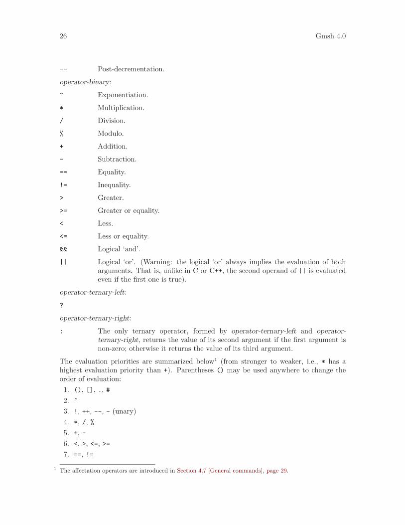
-- Post-decrementation.
operator-binary :
^ Exponentiation.
* Multiplication.
/ Division.
% Modulo.
+ Addition.
- Subtraction.
== Equality.
!= Inequality.
> Greater.
>= Greater or equality.
< Less.
<= Less or equality.
&& Logical ‘and’.
|| Logical ‘or’. (Warning: the logical ‘or’ always implies the evaluation of botharguments. That is, unlike in C or C++, the second operand of || is evaluatedeven if the first one is true).
operator-ternary-left:
?
operator-ternary-right:
: The only ternary operator, formed by operator-ternary-left and operator-ternary-right, returns the value of its second argument if the first argument isnon-zero; otherwise it returns the value of its third argument.
The evaluation priorities are summarized below1 (from stronger to weaker, i.e., * has ahighest evaluation priority than +). Parentheses () may be used anywhere to change theorder of evaluation:
1. (), [], ., #
2. ^
3. !, ++, --, - (unary)
4. *, /, %
5. +, -
6. <, >, <=, >=
7. ==, !=
1 The affectation operators are introduced in Section 4.7 [General commands], page 29.
Chapter 4: General tools 27
8. &&
9. ||
10. ?:
11. =, +=, -=, *=, /=
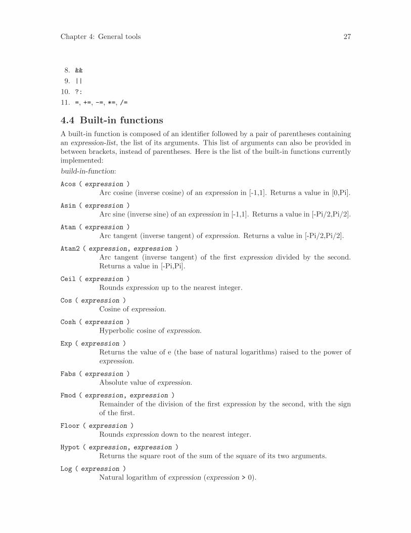
4.4 Built-in functions
A built-in function is composed of an identifier followed by a pair of parentheses containingan expression-list, the list of its arguments. This list of arguments can also be provided inbetween brackets, instead of parentheses. Here is the list of the built-in functions currentlyimplemented:
build-in-function:
Acos ( expression )
Arc cosine (inverse cosine) of an expression in [-1,1]. Returns a value in [0,Pi].
Asin ( expression )
Arc sine (inverse sine) of an expression in [-1,1]. Returns a value in [-Pi/2,Pi/2].
Atan ( expression )
Arc tangent (inverse tangent) of expression. Returns a value in [-Pi/2,Pi/2].
Atan2 ( expression, expression )
Arc tangent (inverse tangent) of the first expression divided by the second.Returns a value in [-Pi,Pi].
Ceil ( expression )
Rounds expression up to the nearest integer.
Cos ( expression )
Cosine of expression.
Cosh ( expression )
Hyperbolic cosine of expression.
Exp ( expression )
Returns the value of e (the base of natural logarithms) raised to the power ofexpression.
Fabs ( expression )
Absolute value of expression.
Fmod ( expression, expression )
Remainder of the division of the first expression by the second, with the signof the first.
Floor ( expression )
Rounds expression down to the nearest integer.
Hypot ( expression, expression )
Returns the square root of the sum of the square of its two arguments.
Log ( expression )
Natural logarithm of expression (expression > 0).
28 Gmsh 4.0
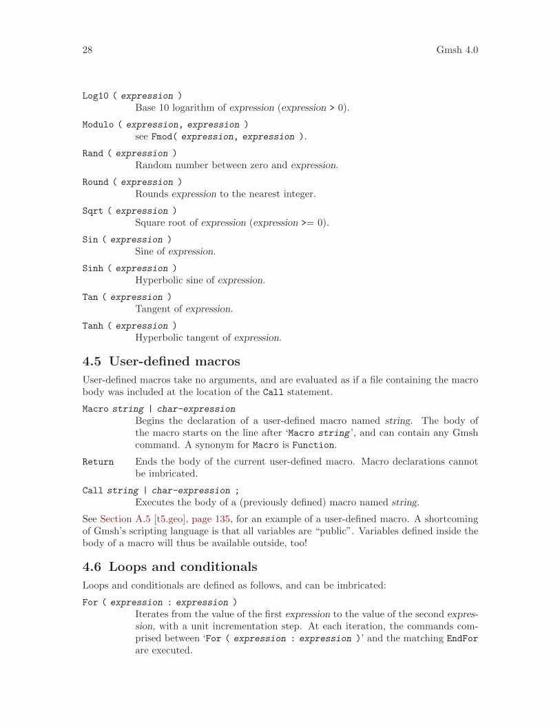
Log10 ( expression )
Base 10 logarithm of expression (expression > 0).
Modulo ( expression, expression )
see Fmod( expression, expression ).
Rand ( expression )
Random number between zero and expression.
Round ( expression )
Rounds expression to the nearest integer.
Sqrt ( expression )
Square root of expression (expression >= 0).
Sin ( expression )
Sine of expression.
Sinh ( expression )
Hyperbolic sine of expression.
Tan ( expression )
Tangent of expression.
Tanh ( expression )
Hyperbolic tangent of expression.
4.5 User-defined macros
User-defined macros take no arguments, and are evaluated as if a file containing the macrobody was included at the location of the Call statement.
Macro string | char-expression
Begins the declaration of a user-defined macro named string. The body ofthe macro starts on the line after ‘Macro string ’, and can contain any Gmshcommand. A synonym for Macro is Function.
Return Ends the body of the current user-defined macro. Macro declarations cannotbe imbricated.
Call string | char-expression ;
Executes the body of a (previously defined) macro named string.
See Section A.5 [t5.geo], page 135, for an example of a user-defined macro. A shortcomingof Gmsh’s scripting language is that all variables are “public”. Variables defined inside thebody of a macro will thus be available outside, too!
4.6 Loops and conditionals
Loops and conditionals are defined as follows, and can be imbricated:
For ( expression : expression )
Iterates from the value of the first expression to the value of the second expres-sion, with a unit incrementation step. At each iteration, the commands com-prised between ‘For ( expression : expression )’ and the matching EndFor
are executed.

Chapter 4: General tools 29
For ( expression : expression : expression )
Iterates from the value of the first expression to the value of the second expres-sion, with a positive or negative incrementation step equal to the third expres-sion. At each iteration, the commands comprised between ‘For ( expression
: expression : expression )’ and the matching EndFor are executed.
For string In { expression : expression }
Iterates from the value of the first expression to the value of the second expres-sion, with a unit incrementation step. At each iteration, the value of the iterateis affected to an expression named string, and the commands comprised between‘For string In { expression : expression }’ and the matching EndFor areexecuted.
For string In { expression : expression : expression }
Iterates from the value of the first expression to the value of the second ex-pression, with a positive or negative incrementation step equal to the thirdexpression. At each iteration, the value of the iterate is affected to an ex-pression named string, and the commands comprised between ‘For string In
{ expression : expression : expression }’ and the matching EndFor areexecuted.
EndFor Ends a matching For command.
If ( expression )
The body enclosed between ‘If ( expression )’ and the matching ElseIf,Else or EndIf, is evaluated if expression is non-zero.
ElseIf ( expression )
The body enclosed between ‘ElseIf ( expression )’ and the next matchingElseIf, Else or EndIf, is evaluated if expression is non-zero and none of theexpression of the previous matching codes If and ElseIf were non-zero.
Else The body enclosed between Else and the matching EndIf is evaluated if noneof the expression of the previous matching codes If and ElseIf were non-zero.
EndIf Ends a matching If command.
See Section A.5 [t5.geo], page 135, for an example of For and If commands. Gmsh doesnot provide any Else (or similar) command at the time of this writing.
4.7 General commands
The following commands can be used anywhere in a Gmsh script:
string = expression;
Creates a new expression identifier string, or affects expression to an existingexpression identifier. Thirteen expression identifiers are predefined (hardcodedin Gmsh’s parser):
Pi Returns 3.1415926535897932.
GMSH_MAJOR_VERSION
Returns Gmsh’s major version number.

30 Gmsh 4.0
GMSH_MINOR_VERSION
Returns Gmsh’s minor version number.
GMSH_PATCH_VERSION
Returns Gmsh’s patch version number.
MPI_Size Returns the number of processors on which Gmsh is running. Itis always 1, except if you compiled Gmsh with ENABLE_MPI (seeAppendix C [Compiling the source code], page 235).
MPI_Rank Returns the rank of the current processor.
Cpu Returns the current CPU time (in seconds).
Memory Returns the current memory usage (in Mb).
TotalMemory
Returns the total memory available (in Mb).
newp Returns the next available point tag. As explained in Chapter 5[Geometry module], page 35, a unique tag must be associated withevery geometrical point: newp permits to know the highest tagalready attributed (plus one). This is mostly useful when writinguser-defined macros (see Section 4.5 [User-defined macros], page 28)or general geometric primitives, when one does not know a prioriwhich tags are already attributed, and which ones are still available.
newl Returns the next available curve tag.
news Returns the next available surface tag.
newv Returns the next available volume tag.
newll Returns the next available curve loop tag.
newsl Returns the next available surface loop tag.
newreg Returns the next available region tag. That is, newreg returns themaximum of newp, newl, news, newv, newll, newsl and all physicalgroup tags2.
string = { };
Creates a new expression list identifier string with an empty list.
string[] = { expression-list };
Creates a new expression list identifier string with the list expression-list, oraffects expression-list to an existing expression list identifier. Parentheses arealso allowed instead of square brackets; although not recommended, bracketsand parentheses can also be completely ommitted.
string [ { expression-list } ] = { expression-list };
Affects each item in the right hand side expression-list to the elements (indexedby the left hand side expression-list) of an existing expression list identifier.The two expression-lists must contain the same number of items. Parenthesescan also be used instead of brackets.
2 For compatibility purposes, the behavior of newl, news, newv and newreg can be modified with theGeometry.OldNewReg option (see Section B.2 [Geometry options list], page 184).

Chapter 4: General tools 31
string += expression;
Adds and affects expression to an existing expression identifier.
string -= expression;
Subtracts and affects expression to an existing expression identifier.
string *= expression;
Multiplies and affects expression to an existing expression identifier.
string /= expression;
Divides and affects expression to an existing expression identifier.
string += { expression-list };
Appends expression-list to an existing expression list or creates a new expressionlist with expression-list.
string -= { expression-list };
Removes the items in expression-list from the existing expression list.
string [ { expression-list } ] += { expression-list };
Adds and affects, item per item, the right hand side expression-list to an existingexpression list identifier. Parentheses can also be used instead of brackets.
string [ { expression-list } ] -= { expression-list };
Subtracts and affects, item per item, the right hand side expression-list toan existing expression list identifier. Parentheses can also be used instead ofbrackets.
string [ { expression-list } ] *= { expression-list };
Multiplies and affects, item per item, the right hand side expression-list toan existing expression list identifier. Parentheses can also be used instead ofbrackets.
string [ { expression-list } ] /= { expression-list };
Divides and affects, item per item, the right hand side expression-list to an ex-isting expression list identifier. Parentheses can also be used instead of brackets.
string = char-expression;
Creates a new character expression identifier string with a givenchar-expression.
string[] = Str( char-expression-list ) ;
Creates a new character expression list identifier string with a given char-expression-list. Parentheses can also be used instead of brackets.
string[] += Str( char-expression-list ) ;
Appends a character expression list to an existing list. Parentheses can also beused instead of brackets.
DefineConstant[ string = expression|char-expression <, ...>];
Creates a new expression identifier string, with value expression, only if has notbeen defined before.

32 Gmsh 4.0
DefineConstant[ string = { expression|char-expression, onelab-options } <,
...>];
Same as the previous case, except that the variable is also ex-changed with the ONELAB database if it has not been defined before. Seehttps://gitlab.onelab.info/doc/tutorial/wikis/ONELAB-syntax-for-Gmsh-and-GetDP
for more information.
SetNumber( char-expression , expression );
Sets the value a numeric ONELAB variable char-expression.
SetString( char-expression , char-expression );
Sets the value a string ONELAB variable char-expression.
real-option = expression;
Affects expression to a real option.
char-option = char-expression;
Affects char-expression to a character option.
color-option = color-expression;
Affects color-expression to a color option.
real-option += expression;
Adds and affects expression to a real option.
real-option -= expression;
Subtracts and affects expression to a real option.
real-option *= expression;
Multiplies and affects expression to a real option.
real-option /= expression;
Divides and affects expression to a real option.
Abort; Aborts the current script.
Exit; Exits Gmsh.
CreateDir char-expression;
Create the directory char-expression.
Printf ( char-expression <, expression-list> );
Prints a character expression in the information window and/or on the ter-minal. Printf is equivalent to the printf C function: char-expression is aformat string that can contain formatting characters (%f, %e, etc.). Note thatall expressions are evaluated as floating point values in Gmsh (see Section 4.2[Expressions], page 21), so that only valid floating point formatting charac-ters make sense in char-expression. See Section A.5 [t5.geo], page 135, for anexample of the use of Printf.
Printf ( char-expression , expression-list ) > char-expression;
Same as Printf above, but output the expression in a file.
Printf ( char-expression , expression-list ) >> char-expression;
Same as Printf above, but appends the expression at the end of the file.
Chapter 4: General tools 33
Error ( char-expression <, expression-list> );
Same as Printf, but raises an error.
Merge char-expression;
Merges a file named char-expression. This command is equivalent to the ‘File->Merge’ menu in the GUI. If the path in char-expression is not absolute, char-expression is appended to the path of the current file.
ShapeFromFile( char-expression );
Merges a BREP or STEP file and returns the tags of the highest-dimensionalentities. Only available with the OpenCASCADE geometry kernel.
Draw; Redraws the scene.
SetChanged;
Force the mesh and post-processing vertex arrays to be regenerated. Useful e.g.for creating animations with changing clipping planes, etc.
BoundingBox;
Recomputes the bounding box of the scene (which is normally computed onlyafter new geometrical entities are added or after files are included or merged).The bounding box is computed as follows:
1. If there is a mesh (i.e., at least one mesh node), the bounding box is takenas the box enclosing all the mesh nodes;
2. If there is no mesh but there is a geometry (i.e., at least one geometricalpoint), the bounding box is taken as the box enclosing all the geometricalpoints;
3. If there is no mesh and no geometry, but there are some post-processingviews, the bounding box is taken as the box enclosing all the primitives inthe views.
BoundingBox { expression, expression, expression, expression, expression,
expression };
Forces the bounding box of the scene to the given expressions (X min, X max,Y min, Y max, Z min, Z max).
Delete Model;
Deletes the current model (all geometrical entities and their associated meshes).
Delete Physicals;
Deletes all physical groups.
Delete Variables;
Deletes all the expressions.
Delete Options;
Deletes the current options and revert to the default values.
Delete string;
Deletes the expression string.
Print char-expression;
Prints the graphic window in a file named char-expression, using the currentPrint.Format (see Section B.1 [General options list], page 155). If the path in

34 Gmsh 4.0
char-expression is not absolute, char-expression is appended to the path of thecurrent file.
Sleep expression;
Suspends the execution of Gmsh during expression seconds.
SystemCall char-expression;
Executes a (blocking) system call.
NonBlockingSystemCall char-expression;
Executes a (non-blocking) system call.
OnelabRun ( char-expression <, char-expression > )
Runs a ONELAB client (first argument is the client name, second optionalarguement is the command line).
SetName char-expression;
Changes the name of the current model.
SetFactory(char-expression);
Changes the current geometry kernel (i.e. determines the CAD kernel that isused for all subsequent geometrical commands). Currently available kernels:"Built-in" and "OpenCASCADE".
SyncModel;
Forces an immediate transfer from the old geometrical database into the newone (this transfer normally occurs right after a file is read).
NewModel;
Creates a new current model.
Include char-expression;
Includes the file named char-expression at the current position in the inputfile. The include command should be given on a line of its own. If the path inchar-expression is not absolute, char-expression is appended to the path of thecurrent file.
4.8 General options
The list of all the general char-options, real-options and color-options (in that order—checkthe default values to see the actual types) is given in Section B.1 [General options list],page 155. Most of these options are accessible in the GUI, but not all of them. Whenrunning Gmsh interactively, changing an option in the script file will modify the option inthe GUI in real time. This permits for example to resize the graphical window in a script,or to interact with animations in the script and in the GUI at the same time.

Chapter 5: Geometry module 35
5 Geometry module
Geometries can be constructed in Gmsh using different underlying CAD kernels, specifiedin .geo files with the SetFactory command.
The built-in CAD kernel (SetFactory("built-in")) provides a simple CAD engine basedon a boundary representation (“BRep”) approach: you need to first define points (usingthe Point command: see below), then curves (using Line, Circle, Spline, . . . , commandsor by extruding points), then surfaces (using for example the Plane Surface or Surface
commands, or by extruding curves), and finally volumes (using the Volume command orby extruding surfaces). The OpenCASCADE CAD kernel (SetFactory("OpenCASCADE"))uses the open source OpenCASCADE
These geometrical entities are called “elementary” in Gmsh’s jargon, and are assigned tags(stricly positive identification numbers) when they are created:
1. each elementary point must possess a unique tag;
2. each elementary curve must possess a unique tag;
3. each elementary surface must possess a unique tag;
4. each elementary volume must possess a unique tag.
Elementary geometrical entities can then be manipulated in various ways, for exampleusing the Translate, Rotate, Scale or Symmetry commands. They can be deleted withthe Delete command, provided that no higher-dimension entity references them. Zero ornegative tags are reserved by the system for special uses: do not use them in your scripts.
Groups of elementary geometrical entities can also be defined and are called “physical”groups. These physical groups cannot be modified by geometry commands: their onlypurpose is to assemble elementary entities into larger groups so that they can be referred toby the mesh module as single entities. As is the case with elementary entities, each physicalpoint, physical curve, physical surface or physical volume must be assigned a unique tag.See Chapter 6 [Mesh module], page 45, for more information about how physical groupsaffect the way meshes are saved.
5.1 Geometry commands
The next subsections describe all the available geometry commands. These commands canbe used anywhere in a Gmsh script file. Note that the following general syntax rule isfollowed for the definition of geometrical entities: “If an expression defines a new entity, itis enclosed between parentheses. If an expression refers to a previously defined entity, it isenclosed between braces.”
5.1.1 Points
Point ( expression ) = { expression, expression, expression <, expression > };
Creates an elementary point. The expression inside the parentheses is thepoint’s tag; the three first expressions inside the braces on the right hand sidegive the three X, Y and Z coordinates of the point in the three-dimensionalEuclidean space; the optional last expression sets the prescribed mesh elementsize at that point. See Section 6.3.1 [Specifying mesh element sizes], page 47,for more information about how this value is used in the meshing process.

36 Gmsh 4.0
Physical Point ( expression | char-expression <, expression> ) <+|->= {
expression-list };
Creates a physical point. The expression inside the parentheses is the physicalpoint’s tag; the expression-list on the right hand side should contain the tags ofall the elementary points that need to be grouped inside the physical point. Ifa char-expression is given instead instead of expression inside the parentheses,a string label is associated with the physical tag, which can be either providedexplicitly (after the comma) or not (in which case a unique tag is automaticallycreated).
5.1.2 Curves
Line ( expression ) = { expression, expression };
Creates a straight line segment. The expression inside the parentheses is theline segment’s tag; the two expressions inside the braces on the right hand sidegive tags of the start and end points of the segment.
Bezier ( expression ) = { expression-list };
Creates a Bezier curve. The expression-list contains the tags of the controlpoints.
BSpline ( expression ) = { expression-list };
Creates a cubic BSpline. The expression-list contains the tags of the controlpoints. Creates a periodic curve if the first and last points are identical.
Spline ( expression ) = { expression-list };
Creates a spline going through the points in expression-list. With the built-ingeometry kernel this constructs a Catmull-Rom spline. With the OpenCAS-CADE kernel, this constructs a C2 BSpline. Creates a periodic curve if the firstand last points are identical.
Circle ( expression ) = { expression, expression, expression <, ...> };
Creates a circle arc. The three expressions on the right-hand-side define thestart point, the center and the end point of the arc. With the built-in geometrykernel the arc should be strictly smaller than Pi. With the OpenCASCADE ker-nel additional expressions can be provided to define a full circle (4th expressionis the radius) or a circle arc between two angles (next 2 expressions).
Ellipse ( expression ) = { expression, expression, expression, expression <,
...> };
Creates an ellipse arc. The four expressions on the right-hand-side define thestart point, the center point, a major axis point and the end point of theellipse. The third point can be omitted with the OpenCASCADE kernel. Withthe OpenCASCADE kernel additional expressions can be provided to define afull ellipse (4th and 5th expressions define the radii along X and Y) or en ellipsearc (next 2 expressions).
Curve Loop ( expression ) = { expression-list };
Creates an oriented loop of curves, i.e. a closed wire. The expression inside theparentheses is the curve loop’s tag; the expression-list on the right hand sideshould contain the tags of all the elementary curves that constitute the curve

Chapter 5: Geometry module 37
loop. A curve loop must be a closed loop, and the elementary curves should beordered and oriented (using negative tags to specify reverse orientation). If theorientation is correct, but the ordering is wrong, Gmsh will actually reorder thelist internally to create a consistent loop. Although Gmsh supports it, it is notrecommended to specify multiple curve loops (or subloops) in a single Curve
Loop command. (Curve loops are used to create surfaces: see Section 5.1.3[Surfaces], page 37.)
Wire ( expression ) = { expression-list };
Creates a path made of curves. Wires are only available with the OpenCAS-CADE kernel. They are used to create ThruSections and extrusions alongpaths.
Physical Curve ( expression | char-expression <, expression> ) <+|->= {
expression-list };
Creates a physical curve. The expression inside the parentheses is the physicalcurve’s tag; the expression-list on the right hand side should contain the tags ofall the elementary curves that need to be grouped inside the physical curve. Ifa char-expression is given instead instead of expression inside the parentheses,a string label is associated with the physical tag, which can be either providedexplicitly (after the comma) or not (in which case a unique tag is automaticallycreated). Specifying negative tags in the expression-list will reverse the orien-tation of the mesh elements belonging to the corresponding elementary curvesin the saved mesh file.
5.1.3 Surfaces
Plane Surface ( expression ) = { expression-list };
Creates a plane surface. The expression inside the parentheses is the planesurface’s tag; the expression-list on the right hand side should contain thetags of all the curve loops defining the surface. The first curve loop definesthe exterior boundary of the surface; all other curve loops define holes in thesurface. A curve loop defining a hole should not have any curves in commonwith the exterior curve loop (in which case it is not a hole, and the two surfacesshould be defined separately). Likewise, a curve loop defining a hole should nothave any curves in common with another curve loop defining a hole in the samesurface (in which case the two curve loops should be combined).
Surface ( expression ) = { expression-list } < In Sphere { expression } >;
Creates a surface filling. With the built-in kernel, the first curve loop should becomposed of either three or four elementary curves. With the built-in kernel,the optional In Sphere argument forces the surface to be a spherical patch (theextra parameter gives the tag of the center of the sphere).
Disk ( expression ) = { expression-list };
Creates a disk. When four expressions are provided on the right hand side (3coordinates of the center and the radius), the disk is circular. A fifth expressiondefines the radius along Y, leading to an ellipse. Disk is only available with theOpenCASCADE kernel.

38 Gmsh 4.0
Rectangle ( expression ) = { expression-list };
Creates a rectangle. The 3 first expressions define the lower-left corner; thenext 2 define the width and height. If a 6th expression is provided, it definesa radius to round the rectangle corners. Rectangle is only available with theOpenCASCADE kernel.
Surface Loop ( expression ) = { expression-list };
Creates a surface loop (a shell). The expression inside the parentheses is thesurface loop’s tag; the expression-list on the right hand side should contain thetags of all the elementary surfaces that constitute the surface loop. A surfaceloop must always represent a closed shell, and the elementary surfaces shouldbe oriented consistently (using negative tags to specify reverse orientation).(Surface loops are used to create volumes: see Section 5.1.4 [Volumes], page 38.)
Physical Surface ( expression | char-expression <, expression> ) <+|->= {
expression-list };
Creates a physical surface. The expression inside the parentheses is the physicalsurface’s tag; the expression-list on the right hand side should contain thetags of all the elementary surfaces that need to be grouped inside the physicalsurface. If a char-expression is given instead instead of expression inside theparentheses, a string label is associated with the physical tag, which can beeither provided explicitly (after the comma) or not (in which case a unique tagis automatically created). Specifying negative tags in the expression-list willreverse the orientation of the mesh elements belonging to the correspondingelementary surfaces in the saved mesh file.
5.1.4 Volumes
Volume ( expression ) = { expression-list };
Creates a volume. The expression inside the parentheses is the volume’s tag;the expression-list on the right hand side should contain the tags of all thesurface loops defining the volume. The first surface loop defines the exteriorboundary of the volume; all other surface loops define holes in the volume. Asurface loop defining a hole should not have any surfaces in common with theexterior surface loop (in which case it is not a hole, and the two volumes shouldbe defined separately). Likewise, a surface loop defining a hole should not haveany surfaces in common with another surface loop defining a hole in the samevolume (in which case the two surface loops should be combined).
Sphere ( expression ) = { expression-list };
Creates a sphere, defined by the 3 coordinates of its center and a radius. Ad-ditional expressions define 3 angle limits. Sphere is only available with theOpenCASCADE kernel.
Box ( expression ) = { expression-list };
Creates a box, defined by the 3 coordinates of a point and the 3 extents. Box
is only available with the OpenCASCADE kernel.
Cylinder ( expression ) = { expression-list };
Creates a cylinder, defined by the 3 coordinates of the center of the first cir-cular face, the 3 components of the vector defining its axis and its radius. An
Chapter 5: Geometry module 39
additional expression defines the angular opening. Cylinder is only availablewith the OpenCASCADE kernel.
Torus ( expression ) = { expression-list };
Creates a torus, defined by the 3 coordinates of its center and 2 radii. Anadditional expression defines the angular opening. Torus is only available withthe OpenCASCADE kernel.
Cone ( expression ) = { expression-list };
Creates a cone, defined by the 3 coordinates of the center of the first circularface, the 3 components of the vector defining its axis and the two radii of thefaces (these radii can be zero). An additional expression defines the angularopening. Cone is only available with the OpenCASCADE kernel.
Wedge ( expression ) = { expression-list };
Creates a right angular wedge, defined by the 3 coordinates of the right-anglepoint and the 3 extends. An additional parameter defines the top X extent(zero by default). Wedge is only available with the OpenCASCADE kernel.
ThruSections ( expression ) = { expression-list };
Creates a volume defined through curve loops. ThruSections is only availablewith the OpenCASCADE kernel.
Ruled ThruSections ( expression ) = { expression-list };
Same as ThruSections, but the surfaces created on the boundary are forcedto be ruled. Ruled ThruSections is only available with the OpenCASCADEkernel.
Physical Volume ( expression | char-expression <, expression> ) <+|->= {
expression-list };
Creates a physical volume. The expression inside the parentheses is the physicalvolume’s tag; the expression-list on the right hand side should contain thetags of all the elementary volumes that need to be grouped inside the physicalvolume. If a char-expression is given instead instead of expression inside theparentheses, a string label is associated with the physical tag, which can beeither provided explicitly (after the comma) or not (in which case a unique tagis automatically created).
5.1.5 Extrusions
Curves, surfaces and volumes can also be created through extrusion of points, curves andsurfaces, respectively. Here is the syntax of the geometrical extrusion commands (go toSection 6.3.2 [Structured grids], page 63, to see how these commands can be extended inorder to also extrude the mesh):
extrude:
Extrude { expression-list } { extrude-list }
Extrudes all elementary entities (points, curves or surfaces) in extrude-list usinga translation. The expression-list should contain three expressions giving theX, Y and Z components of the translation vector.

40 Gmsh 4.0
Extrude { { expression-list }, { expression-list }, expression } {
extrude-list }
Extrudes all elementary entities (points, curves or surfaces) in extrude-list usinga rotation. The first expression-list should contain three expressions giving theX, Y and Z direction of the rotation axis; the second expression-list shouldcontain three expressions giving the X, Y and Z components of any point onthis axis; the last expression should contain the rotation angle (in radians).
Extrude { { expression-list }, { expression-list }, { expression-list },
expression } { extrude-list }
Extrudes all elementary entities (points, curves or surfaces) in extrude-list us-ing a translation combined with a rotation (to produce a “twist”). The firstexpression-list should contain three expressions giving the X, Y and Z compo-nents of the translation vector; the second expression-list should contain threeexpressions giving the X, Y and Z direction of the rotation axis, which shouldmatch the direction of the translation; the third expression-list should containthree expressions giving the X, Y and Z components of any point on this axis;the last expression should contain the rotation angle (in radians).
Extrude { extrude-list }
Extrudes entities in extrude-list using a translation along their normal. Onlyavailable with the built-in geometry kernel.
Extrude { extrude-list } Using Wire { expression-list }
Extrudes entities in extrude-list along the give wire. Only available with theOpenCASCADE geometry kernel.
ThruSections { expression-list }
Creates surfaces through the given curve loops or wires. ThruSections is onlyavailable with the OpenCASCADE kernel.
Ruled ThruSections { expression-list }
Creates ruled surfaces through the given curve loops or wires. Ruled
ThruSections is only available with the OpenCASCADE kernel.
Fillet { expression-list } { expression-list } { expression-list }
Fillets volumes (first list) on some curves (second list), using the provided radii(third list). The radius list can either contain a single radius, as many radii ascurves, or twice as many as curves (in which case different radii are providedfor the begin and end points of the curves). Fillet is only available with theOpenCASCADE kernel.
Chamfer { expression-list } { expression-list } { expression-list } {
expression-list }
Chamfer volumes (first list) on some curves (second list), using the provideddistance (fourth list) measured on the given surfaces (third list). The distancelist can either contain a single distance, as many distances as curves, or twiceas many as curves (in which case the first in each pair is measured on the givencorresponding surface). Chamfer is only available with the OpenCASCADEkernel.
with
Chapter 5: Geometry module 41
extrude-list:
<Physical> Point | Curve | Surface { expression-list-or-all }; ...
As explained in Section 4.2.1 [Floating point expressions], page 21, extrude can be used inan expression, in which case it returns a list of tags. By default, the list contains the “top”of the extruded entity at index 0 and the extruded entity at index 1, followed by the “sides”of the extruded entity at indices 2, 3, etc. For example:
Point(1) = {0,0,0};
Point(2) = {1,0,0};
Line(1) = {1, 2};
out[] = Extrude{0,1,0}{ Curve{1}; };
Printf("top curve = %g", out[0]);
Printf("surface = %g", out[1]);
Printf("side curves = %g and %g", out[2], out[3]);
This behaviour can be changed with the Geometry.ExtrudeReturnLateralEntities op-tion (see Section B.2 [Geometry options list], page 184).
5.1.6 Boolean operations
Boolean operations can be applied on curves, surfaces and volumes. All boolean operationact on two lists of elementary entities. The first list represents the object; the secondrepresents the tool. The general syntax for boolean operations is as follows:
boolean:
BooleanIntersection { boolean-list } { boolean-list }
Computes the intersection of the object and the tool.
BooleanUnion { boolean-list } { boolean-list }
Computes the union of the object and the tool.
BooleanDifference { boolean-list } { boolean-list }
Subtract the tool from the object.
BooleanFragments { boolean-list } { boolean-list }
Computes all the fragments resulting from the intersection of the entities in theobject and in the tool, and makes all interfaces unique.
with
boolean-list:
<Physical> Curve | Surface | Volume { expression-list-or-all }; ... |
Delete ;
If Delete is specified in the boolean-list, the tool and/or the object is deleted.
As explained in Section 4.2.1 [Floating point expressions], page 21, boolean can be used inan expression, in which case it returns the list of tags of the highest dimensional entitiescreated by the boolean operation. See demos/boolean for examples.
An alternative syntax exists for boolean operations, which can be used when it is knownbeforehand that the operation will result in a single (highest-dimensional) entity:
boolean-explicit:

42 Gmsh 4.0
BooleanIntersection ( expression ) = { boolean-list } { boolean-list };
Computes the intersection of the object and the tool and assign the result thetag expression.
BooleanUnion { boolean-list } { boolean-list }
Computes the union of the object and the tool and assign the result the tagexpression.
BooleanDifference { boolean-list } { boolean-list }
Subtract the tool from the object and assign the result the tag expression.
Again, see demos/boolean for examples.
Boolean operations are only available with the OpenCASCADE geometry kernel.
5.1.7 Transformations
Geometrical transformations can be applied to elementary entities, or to copies of elemen-tary entities (using the Duplicata command: see below). The syntax of the transformationcommands is:
transform:
Dilate { { expression-list }, expression } { transform-list }
Scales all elementary entities in transform-list by a factor expression. Theexpression-list should contain three expressions giving the X, Y, and Z coordi-nates of the center of the homothetic transformation.
Dilate { { expression-list }, { expression, expression, expression } } {
transform-list }
Scales all elementary entities in transform-list using different factors along X,Y and Z (the three expressions). The expression-list should contain threeexpressions giving the X, Y, and Z coordinates of the center of the homoth-etic transformation.
Rotate { { expression-list }, { expression-list }, expression } {
transform-list }
Rotates all elementary entities in transform-list by an angle of expression radi-ans. The first expression-list should contain three expressions giving the X, Yand Z direction of the rotation axis; the second expression-list should containthree expressions giving the X, Y and Z components of any point on this axis.
Symmetry { expression-list } { transform-list }
Transforms all elementary entities symmetrically to a plane. The expression-listshould contain four expressions giving the coefficients of the plane’s equation.
Translate { expression-list } { transform-list }
Translates all elementary entities in transform-list. The expression-list shouldcontain three expressions giving the X, Y and Z components of the translationvector.
Boundary { transform-list }
(Not a transformation per-se.) Returns the entities on the boundary of the ele-mentary entities in transform-list, with signs indicating their orientation in the

Chapter 5: Geometry module 43
boundary. To get unsigned tags (e.g. to reuse the output in other commands),apply the Abs function on the returned list.
CombinedBoundary { transform-list }
(Not a transformation per-se.) Returns the boundary of the elementary entities,combined as if a single entity, in transform-list. Useful to compute the boundaryof a complex part.
PointsOf { transform-list }
(Not a transformation per-se.) Returns all the geometrical points on the bound-ary of the elementary entities. Useful to compute the boundary of a complexpart.
with
transform-list:
<Physical> Point | Curve | Surface | Volume { expression-list-or-all }; ... |
Duplicata { <Physical> Point | Curve | Surface | Volume { expression-
list-or-all }; ... } |
transform
5.1.8 Miscellaneous
Here is a list of all other geometry commands currently available:
Coherence;
Removes all duplicate elementary geometrical entities (e.g., points having iden-tical coordinates). Note that with the built-in geometry kernel Gmsh executesthe Coherence command automatically after each geometrical transformation,unless Geometry.AutoCoherence is set to zero (see Section B.2 [Geometry op-tions list], page 184). With the OpenCASCADE geoemtry kernel, Coherenceis simply a shortcut for a BooleanFragments operation on all entities.
< Recursive > Delete { <Physical> Point | Curve | Surface | Volume {
expression-list-or-all }; ... }
Deletes all elementary entities whose tags are given in expression-list-or-all. Ifan entity is linked to another entity (for example, if a point is used as a controlpoint of a curve), Delete has no effect (the curve will have to be deleted beforethe point can). The Recursive variant deletes the entities as well as all itssub-entities of lower dimension.
< Recursive > Hide { <Physical> Point | Curve | Surface | Volume {
expression-list-or-all }; ... }
Hide the entities listed in expression-list-or-all, if General.VisibilityMode isset to 0 or 1.
Hide { : }
Hide all entities, if General.VisibilityMode is set to 0 or 1.
< Recursive > Show { <Physical> Point | Curve | Surface | Volume {
expression-list-or-all }; ... }
Show the entities listed in expression-list-or-all, if General.VisibilityMode isset to 0 or 1.

44 Gmsh 4.0
Show { : }
Show all entities, if General.VisibilityMode is set to 0 or 1.
5.2 Geometry options
The list of all the options that control the behavior of geometry commands, as well as theway geometrical entities are handled in the GUI, is give in Section B.2 [Geometry optionslist], page 184.
Chapter 6: Mesh module 45
6 Mesh module
Gmsh’s mesh module regroups several 1D, 2D and 3D meshing algorithms, all producinggrids conforming in the sense of finite elements (see Section 1.2 [Mesh], page 5):
• The 2D unstructured algorithms generate triangles or both triangles and quadrangles(when Recombine Surface is used: see Section 6.3.3 [Miscellaneous mesh commands],page 66). The 3D unstructured algorithms generate tetrahedra.
• The 2D structured algorithms (transfinite and extrusion) generate triangles by default,but quadrangles can be obtained by using the Recombine commands (see Section 6.3.2[Structured grids], page 63, and Section 6.3.3 [Miscellaneous mesh commands], page 66).The 3D structured algorithms generate tetrahedra, hexahedra, prisms and pyramids,depending on the type of the surface meshes they are based on.
All meshes can be subdivided to generate fully quadrangular or fully hexahedral mesheswith the Mesh.SubdivisionAlgorihm option (see Section B.3 [Mesh options list], page 192).However, beware that the quality of subdivided elements initially generated with an un-structured algorithm can be quite poor.
6.1 Choosing the right unstructured algorithm
Gmsh currently provides a choice between three 2D unstructured algorithms and betweentwo 3D unstructured algorithms. Each algorithm has its own advantages and disadvantages.
For all 2D unstructured algorithms a Delaunay mesh that contains all the points of the1D mesh is initially constructed using a divide-and-conquer algorithm1. Missing edges arerecovered using edge swaps2. After this initial step three different algorithms can be appliedto generate the final mesh:
1. The “MeshAdapt” algorithm3 is based on local mesh modifications. This techniquemakes use of edge swaps, splits, and collapses: long edges are split, short edges arecollapsed, and edges are swapped if a better geometrical configuration is obtained.
2. The “Delaunay” algorithm is inspired by the work of the GAMMA team at INRIA4.New points are inserted sequentially at the circumcenter of the element that has thelargest adimensional circumradius. The mesh is then reconnected using an anisotropicDelaunay criterion.
3. The “Frontal” algorithm is inspired by the work of S. Rebay5.
These algorithms can be ranked as follows:
1 R. A. Dwyer, A simple divide-and-conquer algorithm for computing Delaunay triangulations in O(n logn) expected time, In Proceedings of the second annual symposium on computational geometry, YorktownHeights, 2–4 June 1986.
2 N. P. Weatherill, The integrity of geometrical boundaries in the two-dimensional Delaunay triangulation,Commun. Appl. Numer. Methods 6(2), pp. 101–109, 1990.
3 C. Geuzaine and J.-F. Remacle, Gmsh: a three-dimensional finite element mesh generator with built-inpre- and post-processing facilities, International Journal for Numerical Methods in Engineering 79(11), pp.1309–1331, 2009.
4 P.-L. George and P. Frey, Mesh generation, Hermes, Lyon, 2000.5 S. Rebay, Efficient unstructured mesh generation by means of Delaunay triangulation and Bowyer-Watson
algorithm, J. Comput. Phys. 106, pp. 25–138, 1993.

46 Gmsh 4.0
Robustness Performance Element quality
MeshAdapt 1 3 2
Delaunay 2 1 2
Frontal 3 2 1
For very complex curved surfaces the “MeshAdapt” algorithm is the best choice. Whenhigh element quality is important, the “Frontal” algorithm should be tried. For very largemeshes of plane surfaces the “Delaunay” algorithm is the fastest.
The “Automatic” algorithm tries to select the best algorithm automatically for each surfacein the model. As of Gmsh 2.8, the “Automatic” algorithm selects “Delaunay” for planesurfaces and “MeshAdapt” for all other surfaces.
In 3D two unstructured algorithms are available:
1. The “Delaunay” algorithm is split into two separate steps. First, an initial mesh of theunion of all the volumes in the model is performed using H. Si’s Tetgen algorithm6.Then a three-dimensional version of the 2D Delaunay algorithm described above isapplied.
2. The “Frontal” algorithm uses J. Schoeberl’s Netgen algorithm7.
The “Delaunay” algorithm is the most robust and the fastest, and is the only one thatsupports the Field mechanism to specify element sizes (see Section 6.3.1 [Specifying meshelement sizes], page 47). However, this algorithm will sometimes modify the surface mesh,and is thus not suitable for producing hybrid structured/unstructured grids. In that casethe “Frontal” algorithm should be preferred. The quality of the elements produced by bothalgorithms is comparable. If element quality is important the mesh optimizer(s) should beapplied.
6.2 Elementary entities vs. physical groups
It is usually convenient to combine geometrical entities into more meaningful groups, e.g.to define some mathematical (“domain”, “boundary with Neumann condition”), functional(“left wing”, “fuselage”) or material (“steel”, “carbon”) properties. Such grouping is donein Gmsh’s geometry module (see Chapter 5 [Geometry module], page 35) through “physicalgroups”.
By default in the MSH file format (see Chapter 9 [File formats], page 107), if physicalgroups are defined, the output mesh only contains those elements that belong to at leastone physical group. (Other file formats each treat physical groups in slightly different ways,depending on their capability to define groups.)
To save all mesh element wether or not physical groups are defined, use the Mesh.SaveAlloption (see Section B.3 [Mesh options list], page 192) or specify -save_all on the commandline.
6.3 Mesh commands
The mesh module commands mostly permit to modify the mesh element sizes and specifystructured grid parameters. The actual mesh “actions” (i.e., “mesh the curves”, “mesh the
6 H. Si, Tetgen: a quality tetrahedral mesh generator and three-dimensional Delaunay triangulator, 2004.7 J. Schoeberl, Netgen, an advancing front 2d/3d-mesh generator based on abstract rules, Comput. Visual.
Sci., 1, pp. 41–52, 1997.

Chapter 6: Mesh module 47
surfaces” and “mesh the volumes”) cannot be specified in the script files. They have to begiven either in the GUI or on the command line (see Chapter 3 [Running Gmsh on yoursystem], page 11, and Section 3.3 [Command-line options], page 12).
6.3.1 Specifying mesh element sizes
There are three ways to specify the size of the mesh elements for a given geometry:
1. First, if Mesh.CharacteristicLengthFromPoints is set (it is by default), you cansimply specify desired mesh element sizes at the geometrical points of the model (withthe Point command: see Section 5.1.1 [Points], page 35). The size of the mesh elementswill then be computed by linearly interpolating these values on the initial mesh (seeSection 1.2 [Mesh], page 5). This might sometimes lead to over-refinement in someareas, so that you may have to add “dummy” geometrical entities in the model inorder to get the desired element sizes.
This method works with all the algorithms implemented in the mesh module. The finalelement sizes are of course constrained by the structured algorithms for which the ele-ment sizes are explicitly specified (e.g., transfinite and extruded grids: see Section 6.3.2[Structured grids], page 63).
2. Second, if Mesh.CharacteristicLengthFromCurvature is set (it is not by default),the mesh will be adapted with respect to the curvature of the geometrical entities.
3. Finally, you can specify general mesh size “fields”. Various fields exist:
• A PostView field specifies an explicit background mesh in the form of a scalarpost-processing view (see Section 8.1 [Post-processing commands], page 74, andChapter 9 [File formats], page 107) in which the nodal values are the target elementsizes. This method is very general but it requires a first (usually rough) mesh and away to compute the target sizes on this mesh (usually through an error estimationprocedure, in an iterative process of mesh adaptation). Warning: only parsed(‘.pos’) files can currently be used as background meshes (‘.msh’ files cannot beused, since the mesh used to define the field will be destroyed during the meshingprocess).
(Note that you can also load a background mesh directly from the command lineusing the -bgm option (see Section 3.3 [Command-line options], page 12), or in theGUI by selecting ‘Apply as background mesh’ in the post-processing view optionmenu.)
• A Box field specifies the size of the elements inside and outside of a parallelepipedicregion.
• A Threshold field specifies the size of the mesh according to the distance to somegeometrical entities. These entities can for example be geometry points and curvesspecified by an Attractor field.
• A MathEval field specifies the size of the mesh using an explicit mathematicalfunction.
• A Min field specifies the size as the minimum of the sizes computed using otherfields
• . . .
Fields are supported by all the algorithms except those based on Netgen. The list ofavailable fields with their options is given below.

48 Gmsh 4.0
The three aforementioned methods can be used simultaneously, in which case the smallestelement size is selected at any given point.
All element sizes are further constrained by the Mesh.CharacteristicLengthMin,Mesh.CharacteristicLengthMax and Mesh.CharacteristicLengthFactor options (seeSection B.3 [Mesh options list], page 192)
Here are the mesh commands that are related to the specification of mesh element sizes:
Characteristic Length { expression-list } = expression;
Modify the prescribed mesh element size of the points whose tags are listed inexpression-list. The new value is given by expression.
Field[expression] = string;
Create a new field (with tag expression), of type string.
Field[expression].string = char-expression | expression | expression-list;
Set the option string of the expression-th field.
Background Field = expression;
Select the expression-th field as the one used to compute element sizes. Onlyone background field can be given; if you want to combine several field, use theMin or Max field (see below).
Here is the list of all available fields with their associated options:
Attractor
Compute the distance from the nearest node in a list. It can also be used tocompute the distance from curves, in which case each curve is replaced by NN-odesByEdge equidistant nodes and the distance from those nodes is computed.Options:
EdgesList
Indices of curves in the geometric modeltype: listdefault value: {}
FacesList
Indices of surfaces in the geometric model (Warning, this feature isstill experimental. It might (read: will probably) give wrong resultsfor complex surfaces)type: listdefault value: {}
FieldX Id of the field to use as x coordinate.type: integerdefault value: -1
FieldY Id of the field to use as y coordinate.type: integerdefault value: -1
FieldZ Id of the field to use as z coordinate.type: integerdefault value: -1

Chapter 6: Mesh module 49
NNodesByEdge
Number of nodes used to discretized each curvetype: integerdefault value: 20
NodesList
Indices of nodes in the geometric modeltype: listdefault value: {}
AttractorAnisoCurve
Compute the distance from the nearest curve in a list. Then the mesh sizecan be specified independently in the direction normal to the curve and inthe direction parallel to the curve (Each curve is replaced by NNodesByEdgeequidistant nodes and the distance from those nodes is computed.)Options:
EdgesList
Indices of curves in the geometric modeltype: listdefault value: {}
NNodesByEdge
Number of nodes used to discretized each curvetype: integerdefault value: 20
dMax Maxmium distance, above this distance from the curves, prescribethe maximum mesh sizes.type: floatdefault value: 0.5
dMin Minimum distance, below this distance from the curves, prescribethe minimum mesh sizes.type: floatdefault value: 0.1
lMaxNormal
Maximum mesh size in the direction normal to the closest curve.type: floatdefault value: 0.5
lMaxTangent
Maximum mesh size in the direction tangeant to the closest curve.type: floatdefault value: 0.5
lMinNormal
Minimum mesh size in the direction normal to the closest curve.type: floatdefault value: 0.05

50 Gmsh 4.0
lMinTangent
Minimum mesh size in the direction tangeant to the closest curve.type: floatdefault value: 0.5
Ball The value of this field is VIn inside a spherical ball, VOut outside. The ball isdefined by
||dX||^2 < R^2 &&dX = (X - XC)^2 + (Y-YC)^2 + (Z-ZC)^2Options:
Radius Radiustype: floatdefault value: 0
VIn Value inside the balltype: floatdefault value: 0
VOut Value outside the balltype: floatdefault value: 0
XCenter X coordinate of the ball centertype: floatdefault value: 0
YCenter Y coordinate of the ball centertype: floatdefault value: 0
ZCenter Z coordinate of the ball centertype: floatdefault value: 0
BoundaryLayer
hwall * ratio^(dist/hwall)Options:
AnisoMax Threshold angle for creating a mesh fan in the boundary layertype: floatdefault value: 10000000000
EdgesList
Indices of curves in the geometric model for which a boundary layeris neededtype: listdefault value: {}

Chapter 6: Mesh module 51
FanNodesList
Indices of vertices in the geometric model for which a fan is createdtype: listdefault value: {}
IntersectMetrics
Intersect metrics of all facestype: integerdefault value: 0
NodesList
Indices of vertices in the geometric model for which a BL endstype: listdefault value: {}
Quads Generate recombined elements in the boundary layertype: integerdefault value: 0
hfar Element size far from the walltype: floatdefault value: 1
hwall_n Mesh Size Normal to the The Walltype: floatdefault value: 0.1
hwall_n_nodes
Mesh Size Normal to the The Wall at nodes (overwrite hwall nwhen defined)type: list doubledefault value: {}
ratio Size Ratio Between Two Successive Layerstype: floatdefault value: 1.1
thickness
Maximal thickness of the boundary layertype: floatdefault value: 0.01
Box The value of this field is VIn inside the box, VOut outside the box. The box isgiven by
Xmin <= x <= XMax &&YMin <= y <= YMax &&ZMin <= z <= ZMaxOptions:
52 Gmsh 4.0
VIn Value inside the boxtype: floatdefault value: 0
VOut Value outside the boxtype: floatdefault value: 0
XMax Maximum X coordinate of the boxtype: floatdefault value: 0
XMin Minimum X coordinate of the boxtype: floatdefault value: 0
YMax Maximum Y coordinate of the boxtype: floatdefault value: 0
YMin Minimum Y coordinate of the boxtype: floatdefault value: 0
ZMax Maximum Z coordinate of the boxtype: floatdefault value: 0
ZMin Minimum Z coordinate of the boxtype: floatdefault value: 0
Curvature
Compute the curvature of Field[IField]:
F = div(norm(grad(Field[IField])))Options:
Delta Step of the finite differencestype: floatdefault value: 0
IField Field indextype: integerdefault value: 1
Cylinder The value of this field is VIn inside a frustrated cylinder, VOut outside. Thecylinder is given by
||dX||^2 < R^2 &&(X-X0).A < ||A||^2dX = (X - X0) - ((X - X0).A)/(||A||^2) . A
Chapter 6: Mesh module 53
Options:
Radius Radiustype: floatdefault value: 0
VIn Value inside the cylindertype: floatdefault value: 0
VOut Value outside the cylindertype: floatdefault value: 0
XAxis X component of the cylinder axistype: floatdefault value: 0
XCenter X coordinate of the cylinder centertype: floatdefault value: 0
YAxis Y component of the cylinder axistype: floatdefault value: 0
YCenter Y coordinate of the cylinder centertype: floatdefault value: 0
ZAxis Z component of the cylinder axistype: floatdefault value: 1
ZCenter Z coordinate of the cylinder centertype: floatdefault value: 0
Distance Compute the distance from the nearest node in a list. It can also be used tocompute the distance from curves, in which case each curve is replaced by NN-odesByEdge equidistant nodes and the distance from those nodes is computed.Options:
EdgesList
Indices of curves in the geometric modeltype: listdefault value: {}
FacesList
Indices of surfaces in the geometric model (Warning, this feature isstill experimental. It might (read: will probably) give wrong resultsfor complex surfaces)

54 Gmsh 4.0
type: listdefault value: {}
FieldX Id of the field to use as x coordinate.type: integerdefault value: -1
FieldY Id of the field to use as y coordinate.type: integerdefault value: -1
FieldZ Id of the field to use as z coordinate.type: integerdefault value: -1
NNodesByEdge
Number of nodes used to discretized each curvetype: integerdefault value: 20
NodesList
Indices of nodes in the geometric modeltype: listdefault value: {}
ExternalProcess
**This Field is experimental**Call an external process that received coordinates triple (x,y,z) as binary doubleprecision numbers on stdin and is supposed to write the field value on stdoutas a binary double precision number.NaN,NaN,NaN is sent as coordinate to indicate the end of the process.
Example of client (python2):import osimport structimport mathimport sysif sys.platform == "win32" :import msvcrtmsvcrt.setmode(0, os.O BINARY)msvcrt.setmode(1, os.O BINARY)while(True):
xyz = struct.unpack("ddd", os.read(0,24))if math.isnan(xyz[0]):
breakf = 0.001 + xyz[1]*0.009os.write(1,struct.pack("d",f))
Example of client (python3):import struct

Chapter 6: Mesh module 55
import sysimport mathwhile(True):
xyz = struct.unpack("ddd", sys.stdin.buffer.read(24))if math.isnan(xyz[0]):
breakf = 0.001 + xyz[1]*0.009sys.stdout.buffer.write(struct.pack("d",f))sys.stdout.flush()
Example of client (c, unix):#include <unistd.h>int main(int argc, char **argv) {double xyz[3];while(read(STDIN FILENO, &xyz, 3*sizeof(double)) == 3*sizeof(double))
{
if (xyz[0] != xyz[0]) break; //nandouble f = 0.001 + 0.009 * xyz[1];write(STDOUT FILENO, &f, sizeof(double));
}
return 0;}
Example of client (c, windows):#include <stdio.h>#include <io.h>#include <fcntl.h>int main(int argc, char **argv) {double xyz[3];setmode(fileno(stdin),O BINARY);setmode(fileno(stdout),O BINARY);while(read(fileno(stdin), &xyz, 3*sizeof(double)) == 3*sizeof(double)) {if (xyz[0] != xyz[0])break;
double f = f = 0.01 + 0.09 * xyz[1];write(fileno(stdout), &f, sizeof(double));
}
}
Options:
CommandLine
Command line to launch.type: stringdefault value: ""

56 Gmsh 4.0
Frustum This field is an extended cylinder with inner (i) and outer (o) radiuseson bothendpoints (1 and 2). Length scale is bilinearly interpolated betweenthese loca-tions (inner and outer radiuses, endpoints 1 and 2)The field values for a pointP are given by : u = P1P.P1P2/||P1P2|| r = || P1P - u*P1P2 || Ri =(1-u)*R1i + u*R2i Ro = (1-u)*R1o + u*R2o v = (r-Ri)/(Ro-Ri) lc = (1-v)*((1-u)*v1i + u*v2i ) + v*( (1-u)*v1o + u*v2o ) where (u,v) in [0,1]x[0,1]Options:
R1_inner Inner radius of Frustum at endpoint 1type: floatdefault value: 0
R1_outer Outer radius of Frustum at endpoint 1type: floatdefault value: 1
R2_inner Inner radius of Frustum at endpoint 2type: floatdefault value: 0
R2_outer Outer radius of Frustum at endpoint 2type: floatdefault value: 1
V1_inner Element size at point 1, inner radiustype: floatdefault value: 0.1
V1_outer Element size at point 1, outer radiustype: floatdefault value: 1
V2_inner Element size at point 2, inner radiustype: floatdefault value: 0.1
V2_outer Element size at point 2, outer radiustype: floatdefault value: 1
X1 X coordinate of endpoint 1type: floatdefault value: 0
X2 X coordinate of endpoint 2type: floatdefault value: 0
Y1 Y coordinate of endpoint 1type: floatdefault value: 0

Chapter 6: Mesh module 57
Y2 Y coordinate of endpoint 2type: floatdefault value: 0
Z1 Z coordinate of endpoint 1type: floatdefault value: 1
Z2 Z coordinate of endpoint 2type: floatdefault value: 1.455171629957881e-152
Gradient Compute the finite difference gradient of Field[IField]:
F = (Field[IField](X + Delta/2) - Field[IField](X - Delta/2)) / DeltaOptions:
Delta Finite difference steptype: floatdefault value: 0
IField Field indextype: integerdefault value: 1
Kind Component of the gradient to evaluate: 0 for X, 1 for Y, 2 for Z, 3for the normtype: integerdefault value: 0
IntersectAniso
Take the intersection of 2 anisotropic fields according to Alauzet.Options:
FieldsList
Field indicestype: listdefault value: {}
Laplacian
Compute finite difference the Laplacian of Field[IField]:
F = G(x+d,y,z) + G(x-d,y,z) +G(x,y+d,z) + G(x,y-d,z) +G(x,y,z+d) + G(x,y,z-d) - 6 * G(x,y,z),
where G=Field[IField] and d=DeltaOptions:
58 Gmsh 4.0
Delta Finite difference steptype: floatdefault value: 0.1
IField Field indextype: integerdefault value: 1
LonLat Evaluate Field[IField] in geographic coordinates (longitude, latitude):
F = Field[IField](atan(y/x), asin(z/sqrt(x^2+y^2+z^2))Options:
FromStereo
if = 1, the mesh is in stereographic coordinates. xi = 2Rx/(R+z),eta = 2Ry/(R+z)type: integerdefault value: 0
IField Index of the field to evaluate.type: integerdefault value: 1
RadiusStereo
radius of the sphere of the stereograpic coordinatestype: floatdefault value: 6371000
MathEval Evaluate a mathematical expression. The expression can contain x, y, z forspatial coordinates, F0, F1, ... for field values, and and mathematical functions.Options:
F Mathematical function to evaluate.type: stringdefault value: "F2 + Sin(z)"
MathEvalAniso
Evaluate a metric expression. The expressions can contain x, y, z for spatialcoordinates, F0, F1, ... for field values, and and mathematical functions.Options:
m11 element 11 of the metric tensor.type: stringdefault value: "F2 + Sin(z)"
m12 element 12 of the metric tensor.type: stringdefault value: "F2 + Sin(z)"

Chapter 6: Mesh module 59
m13 element 13 of the metric tensor.type: stringdefault value: "F2 + Sin(z)"
m22 element 22 of the metric tensor.type: stringdefault value: "F2 + Sin(z)"
m23 element 23 of the metric tensor.type: stringdefault value: "F2 + Sin(z)"
m33 element 33 of the metric tensor.type: stringdefault value: "F2 + Sin(z)"
Max Take the maximum value of a list of fields.Options:
FieldsList
Field indicestype: listdefault value: {}
MaxEigenHessian
Compute the maximum eigenvalue of the Hessian matrix of Field[IField], withthe gradients evaluated by finite differences:
F = max(eig(grad(grad(Field[IField]))))Options:
Delta Step used for the finite differencestype: floatdefault value: 0
IField Field indextype: integerdefault value: 1
Mean Simple smoother:
F = (G(x+delta,y,z) + G(x-delta,y,z) +G(x,y+delta,z) + G(x,y-delta,z) +G(x,y,z+delta) + G(x,y,z-delta) +G(x,y,z)) / 7,
where G=Field[IField]Options:

60 Gmsh 4.0
Delta Distance used to compute the mean valuetype: floatdefault value: 0.0003464101615137755
IField Field indextype: integerdefault value: 0
Min Take the minimum value of a list of fields.Options:
FieldsList
Field indicestype: listdefault value: {}
MinAniso Take the intersection of a list of possibly anisotropic fields.Options:
FieldsList
Field indicestype: listdefault value: {}
Octree Pre compute another field on an octree to speed-up evalutionOptions:
InField Id of the field to use as x coordinate.type: integerdefault value: 746138744
Param Evaluate Field IField in parametric coordinates:
F = Field[IField](FX,FY,FZ)
See the MathEval Field help to get a description of valid FX, FY and FZexpressions.Options:
FX X component of parametric functiontype: stringdefault value: ""
FY Y component of parametric functiontype: stringdefault value: ""
FZ Z component of parametric functiontype: stringdefault value: ""

Chapter 6: Mesh module 61
IField Field indextype: integerdefault value: 1
PostView Evaluate the post processing view IView.Options:
CropNegativeValues
return LC MAX instead of a negative value (this option is neededfor backward compatibility with the BackgroundMesh optiontype: booleandefault value: 1
IView Post-processing view indextype: integerdefault value: 0
ViewTag Post-processing view tagtype: integerdefault value: -1
Restrict Restrict the application of a field to a given list of geometrical points, curves,surfaces or volumes.Options:
EdgesList
Curve indicestype: listdefault value: {}
FacesList
Surface indicestype: listdefault value: {}
IField Field indextype: integerdefault value: 1
RegionsList
Volume indicestype: listdefault value: {}
VerticesList
Point indicestype: listdefault value: {}
Structured
Linearly interpolate between data provided on a 3D rectangular structured grid.

62 Gmsh 4.0
The format of the input file is:
Ox Oy OzDx Dy Dznx ny nzv(0,0,0) v(0,0,1) v(0,0,2) ...v(0,1,0) v(0,1,1) v(0,1,2) ...v(0,2,0) v(0,2,1) v(0,2,2) ...... ... ...v(1,0,0) ... ...
where O are the coordinates of the first node, D are the distances between nodesin each direction, n are the numbers of nodes in each direction, and v are thevalues on each node.Options:
FileName Name of the input filetype: pathdefault value: ""
OutsideValue
Value of the field outside the grid (only used if the "SetOutside-Value" option is true).type: floatdefault value: 0
SetOutsideValue
True to use the "OutsideValue" option. If False, the last values ofthe grid are used.type: booleandefault value: 0
TextFormat
True for ASCII input files, false for binary files (4 bite signed inte-gers for n, double precision floating points for v, D and O)type: booleandefault value: 0
Threshold
F = LCMin if Field[IField] <= DistMin,F = LCMax if Field[IField] >= DistMax,F = interpolation between LcMin and LcMax if DistMin < Field[IField] < Dist-MaxOptions:
DistMax Distance from entity after which element size will be LcMaxtype: floatdefault value: 10

Chapter 6: Mesh module 63
DistMin Distance from entity up to which element size will be LcMintype: floatdefault value: 1
IField Index of the field to evaluatetype: integerdefault value: 0
LcMax Element size outside DistMaxtype: floatdefault value: 1
LcMin Element size inside DistMintype: floatdefault value: 0.1
Sigmoid True to interpolate between LcMin and LcMax using a sigmoid,false to interpolate linearlytype: booleandefault value: 0
StopAtDistMax
True to not impose element size outside DistMax (i.e., F = a verybig value if Field[IField] > DistMax)type: booleandefault value: 0
6.3.2 Structured grids
Extrude { expression-list } { extrude-list layers }
Extrudes both the geometry and the mesh using a translation (see Section 5.1.5[Extrusions], page 39). The layers option determines how the mesh is extrudedand has the following syntax:
layers:
Layers { expression } |
Layers { { expression-list }, { expression-list } } |
Recombine < expression >; ...
QuadTriNoNewVerts <RecombLaterals>; |
QuadTriAddVerts <RecombLaterals>; ...
In the first Layers form, expression gives the number of elements to be cre-ated in the (single) layer. In the second form, the first expression-list defineshow many elements should be created in each extruded layer, and the secondexpression-list gives the normalized height of each layer (the list should containa sequence of n numbers 0 < h1 < h2 < . . . < hn <= 1). See Section A.3 [t3.geo],page 131, for an example.
For curve extrusions, the Recombine option will recombine triangles into quad-rangles when possible. For surface extrusions, the Recombine option will re-combine tetrahedra into prisms, hexahedra or pyramids.
Please note that, starting with Gmsh 2.0, region tags cannot be specified ex-plicitly anymore in Layers commands. Instead, as with all other geometry

64 Gmsh 4.0
commands, you must use the automatically created entity identifier created bythe extrusion command. For example, the following extrusion command willreturn the tag of the new “top” surface in num[0] and the tag of the new volumein num[1]:
num[] = Extrude {0,0,1} { Surface{1}; Layers{10}; };
QuadTriNoNewVerts and QuadTriAddVerts allow to connect structured, ex-truded volumes containing quadrangle-faced elements to structured or unstruc-tured tetrahedral volumes, by subdividing into triangles any quadrangles onboundary surfaces shared with tetrahedral volumes. (They have no effect for1D or 2D extrusions.) QuadTriNoNewVerts subdivides any of the region’s quad-faced 3D elements that touch these boundary triangles into pyramids, prisms, ortetrahedra as necessary, all WITHOUT adding new nodes. QuadTriAddVerts
works in a simular way, but subdivides 3D elements touching the boundarytriangles by adding a new node inside each element at the node-based cen-troid. Either method results in a structured extrusion with an outer layerof subdivided elements that interface the inner, unmodified elements to thetriangle-meshed region boundaries.
In some rare cases, due to certain lateral boundary conditions, it may not bepossible make a valid element subdivision with QuadTriNoNewVerts withoutadding additional nodes. In this case, an internal node is created at the node-based centroid of the element. The element is then divided using that node.When an internal node is created with QuadTriNoNewVerts, the user is alertedby a warning message sent for each instance; however, the mesh will still bevalid and conformal.
Both QuadTriNoNewVerts and QuadTriAddVerts can be used with the optionalRecombLaterals keyword. By default, the QuadTri algorithms will mesh anyfree laterals as triangles, if possible. RecombLaterals forces any free lateralsto remain as quadrangles, if possible. Lateral surfaces between two QuadTriregions will always be meshed as quadrangles.
Note that the QuadTri algorithms will handle all potential meshing conflictsalong the lateral surfaces of the extrusion. In other words, QuadTri will notsubdivide a lateral that must remain as quadrangles, nor will it leave a lateralas quadrangles if it must be divided. The user should therefore feel free to mixdifferent types of neighboring regions with a QuadTri meshed region; the meshshould work. However, be aware that the top surface of the QuadTri extrusionwill always be meshed as triangles, unless it is extruded back onto the originalsource in a toroidal loop (a case which also works with QuadTri).
QuadTriNoNewVerts and QuadTriAddVerts may be used interchangeably, butQuadTriAddVerts often gives better element quality.
If the user wishes to interface a structured extrusion to a tetrahedral volumewithout modifying the original structured mesh, the user may create dedicatedinterface volumes around the structured geometry and apply a QuadTri algo-rithm to those volumes only.

Chapter 6: Mesh module 65
Extrude { { expression-list }, { expression-list }, expression } {
extrude-list layers }
Extrudes both the geometry and the mesh using a rotation (see Section 5.1.5[Extrusions], page 39). The layers option is defined as above.
Extrude { { expression-list }, { expression-list }, { expression-list },
expression } { extrude-list layers }
Extrudes both the geometry and the mesh using a combined translation androtation (see Section 5.1.5 [Extrusions], page 39). The layers option is definedas above.
Extrude { Surface { expression-list }; layers < Using Index[expr]; > < Using
View[expr]; > < ScaleLastLayer; > }
Extrudes a boundary layer from the specified surfaces. If no view is speci-fied, the boundary layer is created using gouraud-shaped (smoothed) normalfield. Specifying a boundary layer index allows to extrude several independentboundary layers (with independent normal smoothing).
ScaleLastLayer scales the height of the last (top) layer of each normal’s extru-sion by the average length of the edges in all the source elements that containthe source node (actually, the average of the averages for each element–edgesactually touching the source node are counted twice). This allows the heightof the last layer to vary along with the size of the source elements in order toachieve better element quality. For example, in a boundary layer extruded withthe Layers definition ’Layers{ {1,4,2}, {0.5, 0.6, 1.6} },’ a source node adjacentto elements with an overall average edge length of 5.0 will extrude to have alast layer height = (1.6-0.6) * 5.0 = 5.0.
Transfinite Curve { expression-list-or-all } = expression < Using Progression
| Bump expression >;
Selects the curves in expression-list to be meshed with the 1D transfinitealgorithm. The expression on the right hand side gives the number of nodesthat will be created on the curve (this overrides any other mesh element sizeprescription—see Section 6.3.1 [Specifying mesh element sizes], page 47).The optional argument ‘Using Progression expression ’ instructs thetransfinite algorithm to distribute the nodes following a geometric progression(Progression 2 meaning for example that each line element in the series willbe twice as long as the preceding one). The optional argument ‘Using Bump
expression ’ instructs the transfinite algorithm to distribute the nodes with arefinement at both ends of the curve.
Transfinite Surface { expression-list-or-all } < = { expression-list } > < Left
| Right | Alternate | AlternateRight | AlternateLeft > ;
Selects surfaces to be meshed with the 2D transfinite algorithm. The expression-list on the right-hand-side should contain the tags of three or four points onthe boundary of the surface that define the corners of the transfinite inter-polation. If no tags are given, the transfinite algorithm will try to find thecorners automatically. The optional argument specifies the way the trianglesare oriented when the mesh is not recombined. (Alternate is a synonym forAlternateRight).

66 Gmsh 4.0
Transfinite Volume { expression-list } < = { expression-list } > ;
Selects five- or six-face volumes to be meshed with the 3D transfinite algorithm.The expression-list on the right-hand-side should contain the tags of the sixor eight points on the boundary of the volume that define the corners of thetransfinite interpolation. If no tags are given, the transfinite algorithm will tryto find the corners automatically.
TransfQuadTri { expression-list } ;
Applies the transfinite QuadTri algorithm on the expression-list list of volumes.A transfinite volume with any combination of recombined and un-recombinedtransfinite boundary surfaces is valid when meshed with TransfQuadTri. Whenapplied to non-Transfinite volumes, TransfQuadTri has no effect on those vol-umes.
6.3.3 Miscellaneous
Here is a list of all other mesh commands currently available:
Mesh expression;
Generates expression-D mesh.
RefineMesh;
Refines the current mesh by splitting all elements. If Mesh.SecondOrderLinearis set, the new nodes are inserted by linear interpolatinon. Otherwise they aresnapped on the actual geometry.
OptimizeMesh char-expression;
Optimizes the current mesh with the given algorithm (currently "Gmsh" or"Netgen").
AdaptMesh { expression-list } { expression-list } { { expression-list < , ... >
} };
Performs adaptive mesh generation. Documentation not yet available.
RelocateMesh Point | Curve | Surface { expression-list-or-all };
Relocates the mesh nodes on the given entities using the parametric coordi-nates stored in the nodes. Useful for creating perturbation of meshes e.g. forsensitivity analyzes.
SetOrder expression;
Changes the order of the elements in the current mesh.
PartitionMesh expression;
Partitions the mesh into expression, using current partitioning options.
Point | Curve { expression-list } In Surface { expression };
Embed the point(s) or curve(s) in the given surface. The surface mesh willconform to the mesh of the point(s) or curves(s).
Point | Curve | Surface { expression-list } In Volume { expression };
Embed the point(s), curve(s) or surface(s) in the given volume. The volumemesh will conform to the mesh of the corresponding point(s), curve(s) or sur-face(s). This is only supported with the 3D Delaunay algorithm.

Chapter 6: Mesh module 67
Periodic Curve { expression-list } = { expression-list } ;
Force mesh of curves on the left-hand side (slaves) to match the mesh of thecurves on the right-hand side (masters).
Periodic Surface expression { expression-list } = expression { expression-list
} ;
Force mesh of the surface on the left-hand side (slave, with boundary edgesspecified between braces) to match the mesh of the surface on the right-handside (master, with boundary edges specified between braces).
Periodic Curve | Surface { expression-list } = { expression-list } Affine |
Translate { expression-list } ;
Force mesh of curves or surfaces on the left-hand side (slaves) to match themesh of the curves on the right-hand side (masters), using prescribed geomet-rical transformations. Affine takes a 4 x 4 (or 4 x 3) affine transformationmatrix given by row; Translate takes the 3 components of the translation asin Section 5.1.7 [Transformations], page 42.
Periodic Curve | Surface { expression-list } = { expression-list } Rotate {
expression-list }, { expression-list }, expression } ;
Force mesh of curves or surfaces on the left-hand side (slaves) to match themesh of the curves on the right-hand side (masters), using a rotation specifiedas in Section 5.1.7 [Transformations], page 42.
Coherence Mesh;
Removes all duplicate mesh nodes.
CreateTopology;
Creates a boundary representation from the mesh if the model does not haveone (e.g. when imported from mesh file formats with no BRep representationof the underlying model).
CreateGeometry;
Creates a parametrization for curves and surfaces that do not have one (i.e.discrete curves and surfaces represented solely by meshes, without an underlyingCAD description).
RenumberMeshNodes;
Renumbers the node tags in the current mesh in a contiunous sequence.
RenumberMeshElements;
Renumbers the elements tags in the current mesh in a contiunous sequence.
SetPartition expression { <Physical> Point | Curve | Surface | Volume {
expression-list-or-all }; ... }
Sets the partition tag of the mesh elements in the entities in expression-list toexpression.
< Recursive > Color color-expression { <Physical> Point | Curve | Surface |
Volume { expression-list-or-all }; ... }
Sets the mesh color of the entities in expression-list to color-expression.

68 Gmsh 4.0
< Recursive > Hide { <Physical> Point | Curve | Surface | Volume {
expression-list-or-all }; ... }
Hides the mesh of the entities in expression-list, if General.VisibilityModeis set to 0 or 2.
Hide { : }
Hide the mesh of all entities, if General.VisibilityMode is set to 0 or 2.
Recombine Surface { expression-list-or-all } < = expression >;
Recombines the triangular meshes of the surfaces listed in expression-list intomixed triangular/quadrangular meshes. The optional expression on the righthand side specifies the maximum difference (in degrees) allowed between thelargest angle of a quadrangle and a right angle (a value of 0 would only acceptquadrangles with right angles; a value of 90 would allow degenerate quadrangles;default value is 45).
MeshAlgorithm Surface { expression-list } = expression;
Forces the meshing algorithm per surface.
Compound Curve | Surface { expression-list-or-all } ;
Treats the given entities as a single entity when meshing, i.e. perform cross-patch meshing of the entities.
ReverseMesh Curve | Surface { expression-list-or-all } ;
Reverses the mesh of the given curve(s) or surface(s).
ReorientMesh Volume { expression-list } ;
Reorients the meshes of the bounding surfaces of the given volumes so thatthe normals point outward to the volumes. Currently only available with theOpenCASCADE kernel, as it relies on the STL triangulation.
Save char-expression;
Saves the mesh in a file named char-expression, using the current Mesh.Format(see Section B.3 [Mesh options list], page 192). If the path in char-expressionis not absolute, char-expression is appended to the path of the current file.
< Recursive > Show { <Physical> Point | Curve | Surface | Volume {
expression-list-or-all }; ... }
Shows the mesh of the entities in expression-list, if General.VisibilityModeis set to 0 or 2.
Show { : };
Shows the mesh of all entities, if General.VisibilityMode is set to 0 or 2.
Smoother Surface { expression-list } = expression;
Sets number of elliptic smoothing steps for the surfaces listed in expression-list(smoothing only applies to transfinite meshes at the moment).
Homology ( { expression-list } ) { { expression-list } , { expression-list } };
Compute a basis representation for homology spaces after a mesh has beengenerated. The first expression-list is a list of dimensions whose homology basesare computed; if empty, all bases are computed. The second expression-list isa list physical groups that constitute the computation domain; if empty, the

Chapter 6: Mesh module 69
whole mesh is the domain. The third expression-list is a list of physical groupsthat constitute the relative subdomain of relative homology computation; ifempty, absolute homology is computed. Resulting basis representation chainsare stored as physical groups in the mesh.
Cohomology ( { expression-list } ) { { expression-list } , { expression-list }
};
Similar to command Homology, but computes a basis representation for coho-mology spaces instead.
6.4 Mesh options
The list of all the options that control the behavior of mesh commands, as well as the waymeshes are displayed in the GUI, is given in Section B.3 [Mesh options list], page 192.


Chapter 7: Solver module 71
7 Solver module
External solvers can be driven by Gmsh through the ONELAB http://www.onelab.info
interface. To add a new solver in the solver module, you need to specify itsname (Solver.Name0, Solver.Name1, etc.) and the path to the executable(Solver.Executable0, Solver.Executable1, etc.); see Section B.4 [Solver options list],page 209).
The client-server API for the solver interface is defined in the onelab.h header.See utils/solvers/c++/solver.cpp for a simple example on how to use the ONELABprogramming interface. See the sources of GetDP (http://getdp.info) for a morecomprehensive example.
7.1 Solver options
The list of all the solver options is given in Section B.4 [Solver options list], page 209.


Chapter 8: Post-processing module 73
8 Post-processing module
Gmsh’s post-processing module can handle multiple scalar, vector or tensor datasets alongwith the geometry and the mesh. The datasets can be given in several formats: in human-readable “parsed” format (these are just part of a standard input script, but are usuallyput in separate files with a ‘.pos’ extension), in native MSH files (ASCII or binary fileswith ‘.msh’ extensions: see Chapter 9 [File formats], page 107), or in standard third-partyformats (like MED: http://www.code-aster.org/outils/med/).
Once loaded into Gmsh, scalar fields can be displayed as iso-value curves and surfaces orcolor maps, whereas vector fields can be represented either by three-dimensional arrowsor by displacement maps. (Tensor fields are currently displayed as Von-Mises effectivestresses, min/max eigenvalues, eigenvectors, ellipsis or ellipsoid. To display other (combi-nations of) components, you can use the Force scalar or Force vector options, or usePlugin(MathEval): see Section 8.2 [Post-processing plugins], page 78.)
In Gmsh’s jargon, each dataset is called a “view”. Each view is given a name, and canbe manipulated either individually (each view has its own button in the GUI and can bereferred to by its index in a script) or globally (see the PostProcessing.Link option inSection B.5 [Post-processing options list], page 215).
By default, Gmsh treats all post-processing views as three-dimensional plots, i.e., drawsthe scalar, vector and tensor primitives (points, curves, triangles, tetrahedra, etc.) in 3Dspace. But Gmsh can also represent each post-processing view containing scalar points astwo-dimensional (“X-Y”) plots, either space- or time-oriented:
• in a ‘2D space’ plot, the scalar points are taken in the same order as they are definedin the post-processing view: the abscissa of the 2D graph is the curvilinear abscissaof the curve defined by the point series, and only one curve is drawn using the valuesassociated with the points. If several time steps are available, each time step generatesa new curve;
• in a ‘2D time’ plot, one curve is drawn for each scalar point in the view and the abscissais the time step.
Although visualization is usually mostly an interactive task, Gmsh exposes all the post-processing commands and options to the user in its scripting language to permit a completeautomation of the post-processing process (see e.g., Section A.8 [t8.geo], page 141, andSection A.9 [t9.geo], page 144).
The two following sections summarize all available post-processing commands and options.Most options apply to both 2D and 3D plots (colormaps, point/line sizes, interval types,time step selection, etc.), but some are peculiar to 3D (lightning, element selection, etc.) or2D plots (abscissa labels, etc.). Note that 2D plots can be positioned explicitly inside thegraphical window, or be automatically positioned in order to avoid overlaps.
Sample post-processing files in human-readable “parsed” format and in the native MSHfile format are available in the tutorial directory of Gmsh’s distribution (‘.pos’ and ‘.msh’files). The “parsed” format is defined in the next section (cf. the View command); the MSHformat is defined in Chapter 9 [File formats], page 107.

74 Gmsh 4.0
8.1 Post-processing commands
Alias View[expression];
Creates an alias of the expression-th post-processing view.
Note that Alias creates a logical duplicate of the view without actually du-plicating the data in memory. This is very useful when you want multiplesimultaneous renderings of the same large dataset (usually with different dis-play options), but you cannot afford to store all copies in memory. If what youreally want is multiple physical copies of the data, just merge the file containingthe post-processing view multiple times.
AliasWithOptions View[expression];
Creates an alias of the expression-th post-processing view and copies all theoptions of the expression-th view to the new aliased view.
CopyOptions View[expression, expression];
Copy all the options from the first expression-th post-processing view to thesecond one.
Combine ElementsByViewName;
Combines all the post-processing views having the same name into new views.The combination is done “spatially”, i.e., simply by appending the elements atthe end of the new views.
Combine ElementsFromAllViews | Combine Views;
Combines all the post-processing views into a single new view. The combinationis done “spatially”, i.e., simply by appending the elements at the end of thenew view.
Combine ElementsFromVisibleViews;
Combines all the visible post-processing views into a single new view. Thecombination is done “spatially”, i.e., simply by appending the elements at theend of the new view.
Combine TimeStepsByViewName | Combine TimeSteps;
Combines the data from all the post-processing views having the same nameinto new multi-time-step views. The combination is done “temporally”, i.e., asif the data in each view corresponds to a different time instant. The combinationwill fail if the meshes in all the views are not identical.
Combine TimeStepsFromAllViews;
Combines the data from all the post-processing views into a new multi-time-step view. The combination is done “temporally”, i.e., as if the data in eachview corresponds to a different time instant. The combination will fail if themeshes in all the views are not identical.
Combine TimeStepsFromVisibleViews;
Combines the data from all the visible post-processing views into a new multi-time-step view. The combination is done “temporally”, i.e., as if the data ineach view corresponds to a different time instant. The combination will fail ifthe meshes in all the views are not identical.

Chapter 8: Post-processing module 75
Delete View[expression];
Deletes (removes) the expression-th post-processing view. Note that post-processing view indices start at 0.
Delete Empty Views;
Deletes (removes) all the empty post-processing views.
Background Mesh View[expression];
Applies the expression-th post-processing view as the current background mesh.Note that post-processing view indices start at 0.
Plugin (string) . Run;
Executes the plugin string. The list of default plugins is given in Section 8.2[Post-processing plugins], page 78.
Plugin (string) . string = expression | char-expression;
Sets an option for a given plugin. See Section 8.2 [Post-processing plugins],page 78, for a list of default plugins and Section A.9 [t9.geo], page 144, forsome examples.
Save View[expression] char-expression;
Saves the expression-th post-processing view in a file named char-expression. Ifthe path in char-expression is not absolute, char-expression is appended to thepath of the current file.
SendToServer View[expression] char-expression;
Sends the expression-th post-processing view to the ONELAB server, with pa-rameter name char-expression.
View "string" { string < ( expression-list ) > { expression-list }; ... };
Creates a new post-processing view, named "string". This is an easy and quitepowerful way to import post-processing data: all the values are expressions,you can embed datasets directly into your geometrical descriptions (see, e.g.,Section A.4 [t4.geo], page 133), the data can be easily generated “on-the-fly”(there is no header containing a priori information on the size of the dataset).The syntax is also very permissive, which makes it ideal for testing purposes.
However this “parsed format” is read by Gmsh’s script parser, which makesit inefficient if there are many elements in the dataset. Also, there is no con-nectivity information in parsed views and all the elements are independent (allfields can be discontinuous), so a lot of information can be duplicated. Forlarge datasets, you should thus use the mesh-based post-processing file formatdescribed in Chapter 9 [File formats], page 107, or use one of the standardformats like MED.
More explicitly, the syntax for a parsed View is the following
View "string" {
type ( list-of-coords ) { list-of-values }; ...
< TIME { expression-list }; >
< INTERPOLATION_SCHEME { val-coef-matrix } { val-exp-matrix }
< { geo-coef-matrix } { geo-exp-matrix } > ; >
};
where the 47 object types that can be displayed are:

76 Gmsh 4.0
type #list-of-coords #list-of-values
--------------------------------------------------------------------
Scalar point SP 3 1 * nb-time-steps
Vector point VP 3 3 * nb-time-steps
Tensor point TP 3 9 * nb-time-steps
Scalar line SL 6 2 * nb-time-steps
Vector line VL 6 6 * nb-time-steps
Tensor line TL 6 18 * nb-time-steps
Scalar triangle ST 9 3 * nb-time-steps
Vector triangle VT 9 9 * nb-time-steps
Tensor triangle TT 9 27 * nb-time-steps
Scalar quadrangle SQ 12 4 * nb-time-steps
Vector quadrangle VQ 12 12 * nb-time-steps
Tensor quadrangle TQ 12 36 * nb-time-steps
Scalar tetrahedron SS 12 4 * nb-time-steps
Vector tetrahedron VS 12 12 * nb-time-steps
Tensor tetrahedron TS 12 36 * nb-time-steps
Scalar hexahedron SH 24 8 * nb-time-steps
Vector hexahedron VH 24 24 * nb-time-steps
Tensor hexahedron TH 24 72 * nb-time-steps
Scalar prism SI 18 6 * nb-time-steps
Vector prism VI 18 18 * nb-time-steps
Tensor prism TI 18 54 * nb-time-steps
Scalar pyramid SY 15 5 * nb-time-steps
Vector pyramid VY 15 15 * nb-time-steps
Tensor pyramid TY 15 45 * nb-time-steps
2D text T2 3 arbitrary
3D text T3 4 arbitrary
The coordinates are given ‘by node’, i.e.,
• (coord1, coord2, coord3) for a point,
• (coord1-node1, coord2-node1, coord3-node1,
coord1-node2, coord2-node2, coord3-node2) for a line,
• (coord1-node1, coord2-node1, coord3-node1,
coord1-node2, coord2-node2, coord3-node2,
coord1-node3, coord2-node3, coord3-node3) for a triangle,
• etc.
The ordering of the nodes is given in Section 9.2 [Node ordering], page 112.
The values are given by time step, by node and by component, i.e.:
comp1-node1-time1, comp2-node1-time1, comp3-node1-time1,
comp1-node2-time1, comp2-node2-time1, comp3-node2-time1,
comp1-node3-time1, comp2-node3-time1, comp3-node3-time1,
comp1-node1-time2, comp2-node1-time2, comp3-node1-time2,
comp1-node2-time2, comp2-node2-time2, comp3-node2-time2,
comp1-node3-time2, comp2-node3-time2, comp3-node3-time2,
...
For the 2D text objects, the two first expressions in list-of-coords give the X-Yposition of the string in screen coordinates, measured from the top-left corner ofthe window. If the first (respectively second) expression is negative, the positionis measured from the right (respectively bottom) edge of the window. If thevalue of the first (respectively second) expression is larger than 99999, the string

Chapter 8: Post-processing module 77
is centered horizontally (respectively vertically). If the third expression is equalto zero, the text is aligned bottom-left and displayed using the default font andsize. Otherwise, the third expression is converted into an integer whose eightlower bits give the font size, whose eight next bits select the font (the indexcorresponds to the position in the font menu in the GUI), and whose eight nextbits define the text alignment (0=bottom-left, 1=bottom-center, 2=bottom-right, 3=top-left, 4=top-center, 5=top-right, 6=center-left, 7=center-center,8=center-right).
For the 3D text objects, the three first expressions in list-of-coords give the XYZposition of the string in model (real world) coordinates. The fourth expressionhas the same meaning as the third expression in 2D text objects.
For both 2D and 3D text objects, the list-of-values can contain an arbitrarynumber of char-expressions. If the char-expression starts with file://, theremainder of the string is interpreted as the name of an image file, and theimage is displayed instead of the string. A format string in the form @wxh or@wxh,wx,wy,wz,hx,hy,hz, where w and h are the width and height (in modelcoordinates for T3 or in pixels for T2) of the image, wx,wy,wz is the directionof the bottom edge of the image and hx,hy,hz is the direction of the left edgeof the image.
The optional TIME list can contain a list of expressions giving the value of thetime (or any other variable) for which an evolution was saved.
The optional INTERPOLATION_SCHEME lists can contain the interpolation matri-ces used for high-order adaptive visualization.
Let us assume that the approximation of the view’s value over an elementis written as a linear combination of d basis functions f [i], i=0, ..., d-1 (thecoefficients being stored in list-of-values). Defining f [i] = Sum(j=0, ..., d-1)F[i][j] p[j], with p[j] = u^P[j][0] v^P[j][1] w^P[j][2] (u, v and w being thecoordinates in the element’s parameter space), then val-coef-matrix denotesthe d x d matrix F and val-exp-matrix denotes the d x 3 matrix P.
In the same way, let us also assume that the coordinates x, y and z of theelement are obtained through a geometrical mapping from parameter space asa linear combination of m basis functions g [i], i=0, ..., m-1 (the coefficientsbeing stored in list-of-coords). Defining g [i] = Sum(j=0, ..., m-1) G[i][j] q[j],with q[j] = u^Q[j][0] v^Q[j][1] w^Q[j][2], then geo-coef-matrix denotes the mx m matrix G and geo-exp-matrix denotes the m x 3 matrix Q.
Here are for example the interpolation matrices for a first order quadrangle:INTERPOLATION_SCHEME
{
{1/4,-1/4, 1/4,-1/4},
{1/4, 1/4,-1/4,-1/4},
{1/4, 1/4, 1/4, 1/4},
{1/4,-1/4,-1/4, 1/4}
}
{
{0, 0, 0},
{1, 0, 0},
{0, 1, 0},
{1, 1, 0}

78 Gmsh 4.0
};
8.2 Post-processing plugins
Post-processing plugins permit to extend the functionality of Gmsh’s post-processingmodule. The difference between regular post-processing options (see Section B.5[Post-processing options list], page 215) and post-processing plugins is that regularpost-processing options only change the way the data is displayed, while post-processingplugins either create new post-processing views, or modify the data stored in a view (in adestructive, non-reversible way).
Plugins are available in the GUI by right-clicking on a view button (or by clicking on theblack arrow next to the view button) and then selecting the ‘Plugin’ submenu.
Here is the list of the plugins that are shipped by default with Gmsh:
Plugin(AnalyseCurvedMesh)
Plugin(AnalyseCurvedMesh) analyse all elements of a given dimension. Accord-ing to what is asked, it computes the minimum of the Jacobian determinant(J), the IGE quality measure (Inverse Gradient Error) and/or the ICN qualitymeasure (Inverse Condition Number). Statistics are printed and, if asked, aPview is created for each measure. The plugin hides elements for which themeasure mu > ’Hiding threshold’, where mu is the ICN measure if asked other-wise the IGE measure if asked otherwise the Jacobian determinant.
J is faster to compute but gives information only on validity while the othermeasure gives also information on quality.The IGE measure is related to the error on the gradient of the finite elementsolution. It is the scaled Jacobian for quads and hexes and a new measure fortriangles and tetrahedra.The ICN measure is related to the condition number of the stiffness matrix.(See article "Efficient computation of the minimum of shape quality measureson curvilinear finite elements" for details.)
Parameters:
- JacobianDeterminant = {0, 1}
- IGEMeasure = {0, 1}
- ICNMeasure = {0, 1}
- HidingThreshold = [0, 1]: Hides all element for which min(mu) is strictlygreater than the threshold, where mu is the ICN if ICN measure == 1, oth-erwise mu is the IGE it IGE measure == 1, otherwise mu is the Jacobiandeterminant.If threshold == 0, hides all elements except invalid.
- DrawPView = {0, 1}: Creates a PView of min(J)/max(J), min(IGE) and/or

Chapter 8: Post-processing module 79
min(ICN) according to what is asked. If ’Recompute’ = 1, new PViews arecreated.
- Recompute = {0,1}: Should be 1 if the mesh has changed.
- DimensionOfElements = {-1, 1, 2, 3, 4}: If == -1, analyse element of thegreater dimension. If == 4, analyse 2D and 3D elements. Numeric options:
JacobianDeterminant
Default value: 0
IGEMeasure
Default value: 0
ICNMeasure
Default value: 0
HidingThreshold
Default value: 9
DrawPView
Default value: 0
Recompute
Default value: 0
DimensionOfElements
Default value: -1
Plugin(Annotate)
Plugin(Annotate) adds the text string ‘Text’, in font ‘Font’ and size ‘FontSize’,in the view ‘View’. The string is aligned according to ‘Align’.
If ‘ThreeD’ is equal to 1, the plugin inserts the string in model coordinates atthe position (‘X’,‘Y’,‘Z’). If ‘ThreeD’ is equal to 0, the plugin inserts the stringin screen coordinates at the position (‘X’,‘Y’).
If ‘View’ < 0, the plugin is run on the current view.
Plugin(Annotate) is executed in-place for list-based datasets or creates a newview for other datasets. String options:
Text Default value: "My Text"
Font Default value: "Helvetica"
Align Default value: "Left"
Numeric options:
X Default value: 50
Y Default value: 30
Z Default value: 0

80 Gmsh 4.0
ThreeD Default value: 0
FontSize Default value: 14
View Default value: -1
Plugin(Bubbles)
Plugin(Bubbles) constructs a geometry consisting of ‘bubbles’ inscribed in theVoronoi of an input triangulation. ‘ShrinkFactor’ allows to change the size ofthe bubbles. The plugin expects a triangulation in the ‘z = 0’ plane to exist inthe current model.
Plugin(Bubbles) creates one ‘.geo’ file. String options:
OutputFile
Default value: "bubbles.geo"
Numeric options:
ShrinkFactor
Default value: 0
Plugin(Crack)
Plugin(Crack) creates a crack around the physical group ‘PhysicalGroup’ ofdimension ‘Dimension’ (1 or 2), embedded in a mesh of dimension ‘Dimension’+ 1. The plugin duplicates the vertices and the elements on the crack and storesthem in a new discrete curve (‘Dimension’ = 1) or surface (‘Dimension’ = 2).The elements touching the crack on the “negative” side are modified to usethe newly generated vertices.If ‘OpenBoundaryPhysicalGroup’ is given (> 0),its vertices are duplicated and the crack will be left open on that (part of the)boundary. Otherwise, the lips of the crack are sealed, i.e., its vertices are notduplicated. For 1D cracks, ‘NormalX’, ‘NormalY’ and ‘NormalZ’ provide thereference normal of the surface in which the crack is supposed to be embedded.Numeric options:
Dimension
Default value: 1
PhysicalGroup
Default value: 1
OpenBoundaryPhysicalGroup
Default value: 0
NormalX Default value: 0
NormalY Default value: 0
NormalZ Default value: 1
Plugin(Curl)
Plugin(Curl) computes the curl of the field in the view ‘View’.
If ‘View’ < 0, the plugin is run on the current view.
Plugin(Curl) creates one new view. Numeric options:

Chapter 8: Post-processing module 81
View Default value: -1
Plugin(CurvedBndDist)
Plugin(CurvedBndDist) ...
Plugin(CutBox)
Plugin(CutBox) cuts the view ‘View’ with a rectangular box defined by the4 points (‘X0’,‘Y0’,‘Z0’) (origin), (‘X1’,‘Y1’,‘Z1’) (axis of U), (‘X2’,‘Y2’,‘Z2’)(axis of V) and (‘X3’,‘Y3’,‘Z3’) (axis of W).
The number of points along U, V, W is set with the options ‘NumPointsU’,‘NumPointsV’ and ‘NumPointsW’.
If ‘ConnectPoints’ is zero, the plugin creates points; otherwise, the plugin gen-erates hexahedra, quadrangles, lines or points depending on the values of ‘Num-PointsU’, ‘NumPointsV’ and ‘NumPointsW’.
If ‘Boundary’ is zero, the plugin interpolates the view inside the box; otherwisethe plugin interpolates the view at its boundary.
If ‘View’ < 0, the plugin is run on the current view.
Plugin(CutBox) creates one new view. Numeric options:
X0 Default value: 0
Y0 Default value: 0
Z0 Default value: 0
X1 Default value: 1
Y1 Default value: 0
Z1 Default value: 0
X2 Default value: 0
Y2 Default value: 1
Z2 Default value: 0
X3 Default value: 0
Y3 Default value: 0
Z3 Default value: 1
NumPointsU
Default value: 20
NumPointsV
Default value: 20
NumPointsW
Default value: 20

82 Gmsh 4.0
ConnectPoints
Default value: 1
Boundary Default value: 1
View Default value: -1
Plugin(CutGrid)
Plugin(CutGrid) cuts the view ‘View’ with a rectangular grid defined by the 3points (‘X0’,‘Y0’,‘Z0’) (origin), (‘X1’,‘Y1’,‘Z1’) (axis of U) and (‘X2’,‘Y2’,‘Z2’)(axis of V).
The number of points along U and V is set with the options ‘NumPointsU’ and‘NumPointsV’.
If ‘ConnectPoints’ is zero, the plugin creates points; otherwise, the plugin gen-erates quadrangles, lines or points depending on the values of ‘NumPointsU’and ‘NumPointsV’.
If ‘View’ < 0, the plugin is run on the current view.
Plugin(CutGrid) creates one new view. Numeric options:
X0 Default value: 0
Y0 Default value: 0
Z0 Default value: 0
X1 Default value: 1
Y1 Default value: 0
Z1 Default value: 0
X2 Default value: 0
Y2 Default value: 1
Z2 Default value: 0
NumPointsU
Default value: 20
NumPointsV
Default value: 20
ConnectPoints
Default value: 1
View Default value: -1
Plugin(CutMesh)
Plugin(CutMesh) cuts the mesh of the current GModel with the zero value ofthe levelset defined with the view ’View’.Sub-elements are created in the newmodel (polygons in 2D and polyhedra in 3D) and border elements are created

Chapter 8: Post-processing module 83
on the zero-levelset.
If ‘Split’ is nonzero, the plugin splits the meshalong the edges of the cut elementsin the positive side.
If ’SaveTri’ is nonzero, the sub-elements are saved as simplices.
Plugin(CutMesh) creates one new GModel. Numeric options:
View Default value: -1
Split Default value: 0
SaveTri Default value: 0
Plugin(CutParametric)
Plugin(CutParametric) cuts the view ‘View’ with the parametric function(‘X’(u,v), ‘Y’(u,v), ‘Z’(u,v)), using ‘NumPointsU’ values of the parameter uin [‘MinU’, ‘MaxU’] and ‘NumPointsV’ values of the parameter v in [‘MinV’,‘MaxV’].
If ‘ConnectPoints’ is set, the plugin creates surface or line elements; otherwise,the plugin generates points.
If ‘View’ < 0, the plugin is run on the current view.
Plugin(CutParametric) creates one new view. String options:
X Default value: "2 * Cos(u) * Sin(v)"
Y Default value: "4 * Sin(u) * Sin(v)"
Z Default value: "0.1 + 0.5 * Cos(v)"
Numeric options:
MinU Default value: 0
MaxU Default value: 6.2832
NumPointsU
Default value: 180
MinV Default value: 0
MaxV Default value: 6.2832
NumPointsV
Default value: 180
ConnectPoints
Default value: 0
View Default value: -1

84 Gmsh 4.0
Plugin(CutPlane)
Plugin(CutPlane) cuts the view ‘View’ with the plane ‘A’*X + ‘B’*Y + ‘C’*Z +
‘D’ = 0.
If ‘ExtractVolume’ is nonzero, the plugin extracts the elements on one side ofthe plane (depending on the sign of ‘ExtractVolume’).
If ‘View’ < 0, the plugin is run on the current view.
Plugin(CutPlane) creates one new view. Numeric options:
A Default value: 1
B Default value: 0
C Default value: 0
D Default value: -0.01
ExtractVolume
Default value: 0
RecurLevel
Default value: 4
TargetError
Default value: 0
View Default value: -1
Plugin(CutSphere)
Plugin(CutSphere) cuts the view ‘View’ with the sphere (X-‘Xc’)^2 + (Y-‘Yc’)^2+ (Z-‘Zc’)^2 = ‘R’^2.
If ‘ExtractVolume’ is nonzero, the plugin extracts the elements inside (if ‘Ex-tractVolume’ < 0) or outside (if ‘ExtractVolume’ > 0) the sphere.
If ‘View’ < 0, the plugin is run on the current view.
Plugin(CutSphere) creates one new view. Numeric options:
Xc Default value: 0
Yc Default value: 0
Zc Default value: 0
R Default value: 0.25
ExtractVolume
Default value: 0
RecurLevel
Default value: 4
TargetError
Default value: 0

Chapter 8: Post-processing module 85
View Default value: -1
Plugin(DiscretizationError)
Plugin(DiscretizationError) computes the error between the mesh and the ge-ometry. It does so by supersampling the elements and computing the distancebetween the supersampled points dans their projection on the geometry. Nu-meric options:
SuperSamplingNodes
Default value: 10
Plugin(Distance)
Plugin(Distance) computes distances to physical entities in a mesh.
Define the physical entities to which the distance is computed. If Point=0,Line=0, and Surface=0, then the distance is computed to all the boundaries ofthe mesh (edges in 2D and faces in 3D).
Computation<0. computes the geometrical euclidian distance (warning: differ-ent than the geodesic distance), and Computation=a>0.0 solves a PDE on themesh with the diffusion constant mu = a*bbox, with bbox being the max sizeof the bounding box of the mesh (see paper Legrand 2006).
Min Scale and max Scale, scale the distance function. If min Scale<0 and maxScale<0, then no scaling is applied to the distance function.
Plugin(Distance) creates a new distance view and also saves the view in thefileName.pos file. String options:
Filename Default value: "distance.pos"
Numeric options:
PhysPoint
Default value: 0
PhysLine Default value: 0
PhysSurface
Default value: 0
Computation
Default value: -1
MinScale Default value: -1
MaxScale Default value: -1
Orthogonal
Default value: -1
Plugin(Divergence)
Plugin(Divergence) computes the divergence of the field in the view ‘View’.
86 Gmsh 4.0
If ‘View’ < 0, the plugin is run on the current view.
Plugin(Divergence) creates one new view. Numeric options:
View Default value: -1
Plugin(Eigenvalues)
Plugin(Eigenvalues) computes the three real eigenvalues of each tensor in theview ‘View’.
If ‘View’ < 0, the plugin is run on the current view.
Plugin(Eigenvalues) creates three new scalar views. Numeric options:
View Default value: -1
Plugin(Eigenvectors)
Plugin(Eigenvectors) computes the three (right) eigenvectors of each tensor inthe view ‘View’ and sorts them according to the value of the associated eigen-values.
If ‘ScaleByEigenvalues’ is set, each eigenvector is scaled by its associated eigen-value. The plugin gives an error if the eigenvectors are complex.
If ‘View’ < 0, the plugin is run on the current view.
Plugin(Eigenvectors) creates three new vector view. Numeric options:
ScaleByEigenvalues
Default value: 1
View Default value: -1
Plugin(ExtractEdges)
Plugin(ExtractEdges) extracts sharp edges from a triangular mesh.
Plugin(ExtractEdges) creates one new view. Numeric options:
Angle Default value: 40
IncludeBoundary
Default value: 1
Plugin(ExtractElements)
Plugin(ExtractElements) extracts some elements from the view ‘View’. If ‘Min-Val’ != ‘MaxVal’, it extracts the elements whose ‘TimeStep’-th values (averagedby element) are comprised between ‘MinVal’ and ‘MaxVal’. If ‘Visible’ != 0, itextracts visible elements.
If ‘View’ < 0, the plugin is run on the current view.
Plugin(ExtractElements) creates one new view. Numeric options:

Chapter 8: Post-processing module 87
MinVal Default value: 0
MaxVal Default value: 0
TimeStep Default value: 0
Visible Default value: 1
Dimension
Default value: -1
View Default value: -1
Plugin(FaultZone)
Plugin(FaultZone) convert all the embedded lines of an existing surfacic meshto flat quadrangles. Flat quadrangles represent joint elements suitable to modela fault zone with Code Aster.
‘SurfaceTag’ must be an existing plane surface containing embedded lines. Em-bedded lines must have been added to the surface via the command Line InSurface. The surface must be meshed with quadratic incomplete elements.
‘Thickness’ is the thickness of the flat quadrangles. Set a value different to zerocan be helpful to check the connectivity.
‘Prefix’ is the prefix of the name of physicals containing the new embedded. Allphysicals containing embedded lines are replaced by physicals containing thecorresponding joint elements. String options:
Prefix Default value: "FAMI_"
Numeric options:
SurfaceTag
Default value: 1
Thickness
Default value: 0
Plugin(FieldFromAmplitudePhase)
Plugin(FieldFromAmplitudePhase) builds a complex field ’u’ from amplitude’a’ (complex) and phase ’phi’ given in two different ’Views’ u = a * exp(k*phi),with k the wavenumber.
The result is to be interpolated in a sufficiently fine mesh: ’MeshFile’.
Plugin(FieldFromAmplitudePhase) generates one new view. String options:
MeshFile Default value: "fine.msh"
Numeric options:
Wavenumber
Default value: 5
88 Gmsh 4.0
AmplitudeView
Default value: 0
PhaseView
Default value: 1
Plugin(GaussPoints)
Given an input mesh, Plugin(GaussPoints) creates a view containing the Gausspoints for a given polynomial ‘Order’.
If ‘PhysicalGroup’ is nonzero, the plugin only creates points for the elementsbelonging to the group. Numeric options:
Order Default value: 0
Dimension
Default value: 2
PhysicalGroup
Default value: 0
Plugin(Gradient)
Plugin(Gradient) computes the gradient of the field in the view ‘View’.
If ‘View’ < 0, the plugin is run on the current view.
Plugin(Gradient) creates one new view. Numeric options:
View Default value: -1
Plugin(HarmonicToTime)
Plugin(HarmonicToTime) takes the values in the time steps ‘RealPart’ and‘ImaginaryPart’ of the view ‘View’, and creates a new view containing
‘View’[‘RealPart’] * cos(p) +- ‘View’[‘ImaginaryPart’] * sin(p)withp = 2*Pi*k/‘NumSteps’, k = 0, ..., ‘NumSteps’-1and ’NumSteps’ the total number of time stepsover ’NumPeriods’ periods at frequency ’Frequency’ [Hz].The ’+’ sign is used if ‘TimeSign’>0, the ’-’ sign otherwise.
If ‘View’ < 0, the plugin is run on the current view.
Plugin(HarmonicToTime) creates one new view. Numeric options:
RealPart Default value: 0
ImaginaryPart
Default value: 1
NumSteps Default value: 20
TimeSign Default value: -1

Chapter 8: Post-processing module 89
Frequency
Default value: 1
NumPeriods
Default value: 1
View Default value: -1
Plugin(HomologyComputation)
Plugin(HomologyComputation) computes representative chains of basis ele-ments of (relative) homology and cohomology spaces.
Define physical groups in order to specify the computation domain and therelative subdomain. Otherwise the whole mesh is the domain and the relativesubdomain is empty.
Plugin(HomologyComputation) creates new views, one for each basis element.The resulting basis chains of desired dimension together with the mesh aresaved to the given file. String options:
DomainPhysicalGroups
Default value: ""
SubdomainPhysicalGroups
Default value: ""
ReductionImmunePhysicalGroups
Default value: ""
DimensionOfChainsToSave
Default value: "0, 1, 2, 3"
Filename Default value: "homology.msh"
Numeric options:
ComputeHomology
Default value: 1
ComputeCohomology
Default value: 0
HomologyPhysicalGroupsBegin
Default value: -1
CohomologyPhysicalGroupsBegin
Default value: -1
CreatePostProcessingViews
Default value: 1
ReductionOmit
Default value: 1
ReductionCombine
Default value: 3
90 Gmsh 4.0
PostProcessSimplify
Default value: 1
ReductionHeuristic
Default value: 1
Plugin(HomologyPostProcessing)
Plugin(HomologyPostProcessing) operates on representative basis chains of ho-mology and cohomology spaces. Functionality:
1. (co)homology basis transformation:’TransformationMatrix’: Integer matrix of the transformation.’PhysicalGroupsOfOperatedChains’: (Co)chains of a (co)homology space basisto be transformed.Results a new (co)chain basis that is an integer cobination of the given basis.
2. Make basis representations of a homology space and a cohomology spacecompatible:’PhysicalGroupsOfOperatedChains’: Chains of a homology space basis.’PhysicalGroupsOfOperatedChains2’: Cochains of a cohomology space basis.Results a new basis for the homology space such that the incidence matrix ofthe new basis and the basis of the cohomology space is the identity matrix.
Options:’PhysicalGroupsToTraceResults’: Trace the resulting (co)chains to the givenphysical groups.’PhysicalGroupsToProjectResults’: Project the resulting (co)chains to the com-plement of the given physical groups.’NameForResultChains’: Post-processing view name prefix for the results.’ApplyBoundaryOperatorToResults’: Apply boundary operator to the result-ing chains.
String options:
TransformationMatrix
Default value: "1, 0; 0, 1"
PhysicalGroupsOfOperatedChains
Default value: "1, 2"
PhysicalGroupsOfOperatedChains2
Default value: ""
PhysicalGroupsToTraceResults
Default value: ""
PhysicalGroupsToProjectResults
Default value: ""
NameForResultChains
Default value: "c"

Chapter 8: Post-processing module 91
Numeric options:
ApplyBoundaryOperatorToResults
Default value: 0
Plugin(Integrate)
Plugin(Integrate) integrates a scalar field over all the elements of the view‘View’ (if ‘Dimension’ < 0), or over all elements of the prescribed dimension (if‘Dimension’ > 0). If the field is a vector field,the circulation/flux of the fieldover line/surface elements is calculated.
If ‘View’ < 0, the plugin is run on the current view.
If ‘OverTime’ = i > -1 , the plugin integrates the scalar view over time insteadof over space, starting at iteration i.If ‘Visible’ = 1, the plugin only integratesovervisible entities.
Plugin(Integrate) creates one new view. Numeric options:
View Default value: -1
OverTime Default value: -1
Dimension
Default value: -1
Visible Default value: 1
Plugin(Isosurface)
Plugin(Isosurface) extracts the isosurface of value ‘Value’ from the view ‘View’,and draws the ‘OtherTimeStep’-th step of the view ‘OtherView’ on this isosur-face.
If ‘ExtractVolume’ is nonzero, the plugin extracts the isovolume with valuesgreater (if ‘ExtractVolume’ > 0) or smaller (if ‘ExtractVolume’ < 0) than theisosurface ‘Value’.
If ‘OtherTimeStep’ < 0, the plugin uses, for each time step in ‘View’, the corre-sponding time step in ‘OtherView’. If ‘OtherView’ < 0, the plugin uses ‘View’as the value source.
If ‘View’ < 0, the plugin is run on the current view.
Plugin(Isosurface) creates as many views as there are time steps in ‘View’.Numeric options:
Value Default value: 0
ExtractVolume
Default value: 0
RecurLevel
Default value: 4

92 Gmsh 4.0
TargetError
Default value: 0
View Default value: -1
OtherTimeStep
Default value: -1
OtherView
Default value: -1
Plugin(Lambda2)
Plugin(Lambda2) computes the eigenvalues Lambda(1,2,3) of the tensor (S ikS kj + Om ik Om kj), where S ij = 0.5 (ui,j + uj,i) and Om ij = 0.5 (ui,j - uj,i)are respectively the symmetric and antisymmetric parts of the velocity gradienttensor.
Vortices are well represented by regions where Lambda(2) is negative.
If ‘View’ contains tensor elements, the plugin directly uses the tensors as thevalues of the velocity gradient tensor; if ‘View’ contains vector elements, theplugin uses them as the velocities from which to derive the velocity gradienttensor.
If ‘View’ < 0, the plugin is run on the current view.
Plugin(Lambda2) creates one new view. Numeric options:
Eigenvalue
Default value: 2
View Default value: -1
Plugin(LongitudeLatitude)
Plugin(LongituteLatitude) projects the view ‘View’ in longitude-latitude.
If ‘View’ < 0, the plugin is run on the current view.
Plugin(LongituteLatitude) is executed in place. Numeric options:
View Default value: -1
Plugin(MakeSimplex)
Plugin(MakeSimplex) decomposes all non-simplectic elements (quadrangles,prisms, hexahedra, pyramids) in the view ‘View’ into simplices (triangles,tetrahedra).
If ‘View’ < 0, the plugin is run on the current view.
Plugin(MakeSimplex) is executed in-place. Numeric options:
View Default value: -1

Chapter 8: Post-processing module 93
Plugin(MathEval)
Plugin(MathEval) creates a new view using data from the time step ‘TimeStep’in the view ‘View’.
If only ‘Expression0’ is given (and ‘Expression1’, ..., ‘Expression8’ are allempty), the plugin creates a scalar view. If ‘Expression0’, ‘Expression1’ and/or‘Expression2’ are given (and ‘Expression3’, ..., ‘Expression8’ are all empty) theplugin creates a vector view. Otherwise the plugin creates a tensor view.
In addition to the usual mathematical functions (Exp, Log, Sqrt, Sin, Cos,Fabs, etc.) and operators (+, -, *, /, ^), all expressions can contain:
- the symbols v0, v1, v2, ..., vn, which represent the n components in ‘View’;
- the symbols w0, w1, w2, ..., wn, which represent the n components of‘OtherView’, at time step ‘OtherTimeStep’;
- the symbols x, y and z, which represent the three spatial coordinates.
If ‘TimeStep’ < 0, the plugin extracts data from all the time steps in the view.
If ‘View’ < 0, the plugin is run on the current view.
Plugin(MathEval) creates one new view.If ‘PhysicalRegion’ < 0, the plugin isrun on all physical regions.
Plugin(MathEval) creates one new view. String options:
Expression0
Default value: "Sqrt(v0^2+v1^2+v2^2)"
Expression1
Default value: ""
Expression2
Default value: ""
Expression3
Default value: ""
Expression4
Default value: ""
Expression5
Default value: ""
Expression6
Default value: ""
Expression7
Default value: ""

94 Gmsh 4.0
Expression8
Default value: ""
Numeric options:
TimeStep Default value: -1
View Default value: -1
OtherTimeStep
Default value: -1
OtherView
Default value: -1
ForceInterpolation
Default value: 0
PhysicalRegion
Default value: -1
Plugin(MeshSubEntities)
Plugin(MeshSubEntities) creates mesh elements for the entities of dimension‘OutputDimension’ (0 for vertices, 1 for edges, 2 for faces) of the ‘InputPhys-icalGroup’ of dimension ‘InputDimension’. The plugin creates new elementsbelonging to ‘OutputPhysicalGroup’. Numeric options:
InputDimension
Default value: 1
InputPhysicalGroup
Default value: 1
OuputDimension
Default value: 0
OuputPhysicalGroup
Default value: 2000
Plugin(MeshVolume)
Plugin(MeshVolume) computes the volume of the mesh. Only the elementstagged with the physical given in ’Physical’ and with the dimension given in’Dimension’ are taken into account. If ’Physical’ is equal to -1, the entire mesh(of the given dimension) is considered. Numeric options:
Physical Default value: -1
Dimension
Default value: 3
Plugin(MinMax)
Plugin(MinMax) computes the min/max of a view.
If ‘View’ < 0, the plugin is run on the current view. If ‘OverTime’ = 1, theplugin calculates the min/max over space and time. If ‘Argument’ = 1, theplugin calculates the min/max and the argmin/argmax. If ‘Visible’ = 1, the

Chapter 8: Post-processing module 95
plugin is only applied to visible entities.
Plugin(MinMax) creates two new views. Numeric options:
View Default value: -1
OverTime Default value: 0
Argument Default value: 0
Visible Default value: 1
Plugin(ModifyComponents)
Plugin(ModifyComponents) modifies the components of the ‘TimeStep’-th timestep in the view ‘View’, using the expressions provided in ‘Expression0’, ...,‘Expression8’. If an expression is empty, the corresponding component in theview is not modified.
The expressions can contain:
- the usual mathematical functions (Log, Sqrt, Sin, Cos, Fabs, ...) and operators(+, -, *, /, ^);
- the symbols x, y and z, to retrieve the coordinates of the current node;
- the symbols Time and TimeStep, to retrieve the current time and time stepvalues;
- the symbols v0, v1, v2, ..., v8, to retrieve each component of the field in ‘View’at the ‘TimeStep’-th time step;
- the symbols w0, w1, w2, ..., w8, to retrieve each component of the field in‘OtherView’ at the ‘OtherTimeStep’-th time step. If ‘OtherView’ and ‘View’ arebased on different spatial grids, or if their data types are different, ‘OtherView’is interpolated onto ‘View’.
If ‘TimeStep’ < 0, the plugin automatically loops over all the time steps in‘View’ and evaluates the expressions for each one.
If ‘OtherTimeStep’ < 0, the plugin uses ‘TimeStep’ instead.
If ‘View’ < 0, the plugin is run on the current view.
If ‘OtherView’ < 0, the plugin uses ‘View’ instead.
Plugin(ModifyComponents) is executed in-place. String options:
Expression0
Default value: "v0 * Sin(x)"

96 Gmsh 4.0
Expression1
Default value: ""
Expression2
Default value: ""
Expression3
Default value: ""
Expression4
Default value: ""
Expression5
Default value: ""
Expression6
Default value: ""
Expression7
Default value: ""
Expression8
Default value: ""
Numeric options:
TimeStep Default value: -1
View Default value: -1
OtherTimeStep
Default value: -1
OtherView
Default value: -1
ForceInterpolation
Default value: 0
Plugin(ModulusPhase)
Plugin(ModulusPhase) interprets the time steps ‘realPart’ and ‘imaginaryPart’in the view ‘View’ as the real and imaginary parts of a complex field and replacesthem with their corresponding modulus and phase.
If ‘View’ < 0, the plugin is run on the current view.
Plugin(ModulusPhase) is executed in-place. Numeric options:
RealPart Default value: 0
ImaginaryPart
Default value: 1
View Default value: -1
Plugin(NearToFarField)
Plugin(NearToFarField) computes the far field pattern from the near electric Eand magnetic H fields on a surface enclosing the radiating device (antenna).
Chapter 8: Post-processing module 97
Parameters: the wavenumber, the angular discretisation (phi in [0, 2*Pi] andtheta in [0, Pi]) of the far field sphere and the indices of the views containing thecomplex-valued E and H fields. If ‘Normalize’ is set, the far field is normalizedto 1. If ‘dB’ is set, the far field is computed in dB. If ‘NegativeTime’ is set,E and H are assumed to have exp(-iwt) time dependency; otherwise they areassume to have exp(+iwt) time dependency. If ‘MatlabOutputFile’ is given theraw far field data is also exported in Matlab format.
Plugin(NearToFarField) creates one new view. String options:
MatlabOutputFile
Default value: "farfield.m"
Numeric options:
Wavenumber
Default value: 1
PhiStart Default value: 0
PhiEnd Default value: 6.28319
NumPointsPhi
Default value: 60
ThetaStart
Default value: 0
ThetaEnd Default value: 3.14159
NumPointsTheta
Default value: 30
EView Default value: 0
HView Default value: 1
Normalize
Default value: 1
dB Default value: 1
NegativeTime
Default value: 0
RFar Default value: 0
Plugin(NearestNeighbor)
Plugin(NearestNeighbor) computes the distance from each point in ‘View’ toits nearest neighbor.
If ‘View’ < 0, the plugin is run on the current view.
Plugin(NearestNeighbor) is executed in-place. Numeric options:
View Default value: -1

98 Gmsh 4.0
Plugin(NewView)
Plugin(NewView) creates a new model-based view from the current mesh, with‘NumComp’ field components.
If ‘ViewTag’ is positive, force that tag for the created view. String options:
Type Default value: "NodeData"
Numeric options:
NumComp Default value: 1
ViewTag Default value: -1
Plugin(Particles)
Plugin(Particles) computes the trajectory of particules in the force field givenby the ‘TimeStep’-th time step of a vector view ‘View’.
The plugin takes as input a grid defined by the 3 points (‘X0’,‘Y0’,‘Z0’)(origin), (‘X1’,‘Y1’,‘Z1’) (axis of U) and (‘X2’,‘Y2’,‘Z2’) (axis of V).
The number of particles along U and V that are to be transported is set withthe options ‘NumPointsU’ and ‘NumPointsV’. The equation
A2 * d^2X(t)/dt^2 + A1 * dX(t)/dt + A0 * X(t) = F
is then solved with the initial conditions X(t=0) chosen as the grid,dX/dt(t=0)=0, and with F interpolated from the vector view.
Time stepping is done using a Newmark scheme with step size ‘DT’ and‘MaxIter’ maximum number of iterations.
If ‘View’ < 0, the plugin is run on the current view.
Plugin(Particles) creates one new view containing multi-step vector points.Numeric options:
X0 Default value: 0
Y0 Default value: 0
Z0 Default value: 0
X1 Default value: 1
Y1 Default value: 0
Z1 Default value: 0
X2 Default value: 0
Y2 Default value: 1
Z2 Default value: 0

Chapter 8: Post-processing module 99
NumPointsU
Default value: 10
NumPointsV
Default value: 1
A2 Default value: 1
A1 Default value: 0
A0 Default value: 0
DT Default value: 0.1
MaxIter Default value: 100
TimeStep Default value: 0
View Default value: -1
Plugin(Probe)
Plugin(Probe) gets the value of the view ‘View’ at the point (‘X’,‘Y’,‘Z’).
If ‘View’ < 0, the plugin is run on the current view.
Plugin(Probe) creates one new view. Numeric options:
X Default value: 0
Y Default value: 0
Z Default value: 0
View Default value: -1
Plugin(Remove)
Plugin(Remove) removes the marked items from the view ‘View’.
If ‘View’ < 0, the plugin is run on the current view.
Plugin(Remove) is executed in-place. Numeric options:
Text2D Default value: 1
Text3D Default value: 1
Points Default value: 0
Lines Default value: 0
Triangles
Default value: 0
Quadrangles
Default value: 0
Tetrahedra
Default value: 0

100 Gmsh 4.0
Hexahedra
Default value: 0
Prisms Default value: 0
Pyramids Default value: 0
Scalar Default value: 1
Vector Default value: 1
Tensor Default value: 1
View Default value: -1
Plugin(Scal2Tens)
Plugin(Scal2Tens) converts some scalar fields into a tensor field. The number ofcomponents must be given (max. 9). The new view ’NameNewView’ containsthe new tensor field. If the number of a view is -1, the value of the correspondingcomponent is 0. String options:
NameNewView
Default value: "NewView"
Numeric options:
NumberOfComponents
Default value: 9
View0 Default value: -1
View1 Default value: -1
View2 Default value: -1
View3 Default value: -1
View4 Default value: -1
View5 Default value: -1
View6 Default value: -1
View7 Default value: -1
View8 Default value: -1
Plugin(Scal2Vec)
Plugin(Scal2Vec) converts the scalar fields into a vectorial field. The new view’NameNewView’ contains it. If the number of a view is -1, the value of thecorresponding component of the vector field is 0. String options:
NameNewView
Default value: "NewView"
Numeric options:
ViewX Default value: -1
ViewY Default value: -1
Chapter 8: Post-processing module 101
ViewZ Default value: -1
Plugin(ShowNeighborElements)
Plugin(ShowNeighborElements) allows to set visible some given elements and alayer of elements around them, the other being set invisible. Numeric options:
NumLayers
Default value: 1
Element1 Default value: 0
Element2 Default value: 0
Element3 Default value: 0
Element4 Default value: 0
Element5 Default value: 0
Plugin(SimplePartition)
Plugin(SimplePartition) partitions the current mesh into ‘NumSlices’ slices,along the X-, Y- or Z-axis depending on the value of ‘Direction’ (0,1,2). Theplugin creates partition topology if ‘CreateTopology’ is set. String options:
Mapping Default value: "t"
Numeric options:
NumSlices
Default value: 4
Direction
Default value: 0
CreateTopology
Default value: 1
Plugin(Skin)
Plugin(Skin) extracts the boundary (skin) of the current mesh (if ‘FromMesh’= 1), or from the the view ‘View’ (in which case it creates a new view). If‘View’ < 0 and ‘FromMesh’ = 0, the plugin is run on the current view.If ‘Visible’ is set, the plugin only extracts the skin of visible entities. Numericoptions:
Visible Default value: 1
FromMesh Default value: 0
View Default value: -1
Plugin(Smooth)
Plugin(Smooth) averages the values at the nodes of the view ‘View’.
If ‘View’ < 0, the plugin is run on the current view.
Plugin(Smooth) is executed in-place. Numeric options:
View Default value: -1

102 Gmsh 4.0
Plugin(SphericalRaise)
Plugin(SphericalRaise) transforms the coordinates of the elements in the view‘View’ using the values associated with the ‘TimeStep’-th time step.
Instead of elevating the nodes along the X, Y and Z axes as with theView[‘View’].RaiseX, View[‘View’].RaiseY and View[‘View’].RaiseZ options,the raise is applied along the radius of a sphere centered at (‘Xc’, ‘Yc’, ‘Zc’).
To produce a standard radiation pattern, set ‘Offset’ to minus the radius ofthe sphere the original data lives on.
If ‘View’ < 0, the plugin is run on the current view.
Plugin(SphericalRaise) is executed in-place. Numeric options:
Xc Default value: 0
Yc Default value: 0
Zc Default value: 0
Raise Default value: 1
Offset Default value: 0
TimeStep Default value: 0
View Default value: -1
Plugin(StreamLines)
Plugin(StreamLines) computes stream lines from the ‘TimeStep’-th time stepof a vector view ‘View’ and optionally interpolates the scalar view ‘OtherView’on the resulting stream lines.
The plugin takes as input a grid defined by the 3 points (‘X0’,‘Y0’,‘Z0’) (origin),(‘X1’,‘Y1’,‘Z1’) (axis of U) and (‘X2’,‘Y2’,‘Z2’) (axis of V).
The number of points along U and V that are to be transported is set with theoptions ‘NumPointsU’ and ‘NumPointsV’. The equation
dX(t)/dt = V(x,y,z)
is then solved with the initial condition X(t=0) chosen as the grid and withV(x,y,z) interpolated on the vector view.
The time stepping scheme is a RK44 with step size ‘DT’ and ‘MaxIter’ maxi-mum number of iterations.
If ‘TimeStep’ < 0, the plugin tries to compute streamlines of the unsteady flow.
If ‘View’ < 0, the plugin is run on the current view.

Chapter 8: Post-processing module 103
Plugin(StreamLines) creates one new view. This view contains multi-step vec-tor points if ‘OtherView’ < 0, or single-step scalar lines if ‘OtherView’ >= 0.Numeric options:
X0 Default value: 0
Y0 Default value: 0
Z0 Default value: 0
X1 Default value: 1
Y1 Default value: 0
Z1 Default value: 0
X2 Default value: 0
Y2 Default value: 1
Z2 Default value: 0
NumPointsU
Default value: 10
NumPointsV
Default value: 1
DT Default value: 0.1
MaxIter Default value: 100
TimeStep Default value: 0
View Default value: -1
OtherView
Default value: -1
Plugin(Summation)
Plugin(Summation) sums every time steps of ’Reference View’ and (every)’Other View X’and store the result in a new view.If ’View 0’ < 0 then the current view is selected.If ’View 1...8’ < 0 then this view is skipped.Views can have diffrent number of time stepsWarning: the Plugin assume that every views sharethe same mesh and thatmeshes do not move between time steps! String options:
Resuling View Name
Default value: "default"
Numeric options:
View 0 Default value: -1
View 1 Default value: -1
View 2 Default value: -1
104 Gmsh 4.0
View 3 Default value: -1
View 4 Default value: -1
View 5 Default value: -1
View 6 Default value: -1
View 7 Default value: -1
Plugin(Tetrahedralize)
Plugin(Tetrahedralize) tetrahedralizes the points in the view ‘View’.
If ‘View’ < 0, the plugin is run on the current view.
Plugin(Tetrahedralize) creates one new view. Numeric options:
View Default value: -1
Plugin(ThinLayerFixMesh)
Fix the mesh in thin parts
Plugin(Transform)
Plugin(Transform) transforms the homogeneous node coordinates (x,y,z,1) ofthe elements in the view ‘View’ by the matrix
[‘A11’ ‘A12’ ‘A13’ ‘Tx’][‘A21’ ‘A22’ ‘A23’ ‘Ty’][‘A31’ ‘A32’ ‘A33’ ‘Tz’].
If ‘SwapOrientation’ is set, the orientation of the elements is reversed.
If ‘View’ < 0, the plugin is run on the current view.
Plugin(Transform) is executed in-place. Numeric options:
A11 Default value: 1
A12 Default value: 0
A13 Default value: 0
A21 Default value: 0
A22 Default value: 1
A23 Default value: 0
A31 Default value: 0
A32 Default value: 0
A33 Default value: 1
Tx Default value: 0
Ty Default value: 0

Chapter 8: Post-processing module 105
Tz Default value: 0
SwapOrientation
Default value: 0
View Default value: -1
Plugin(Triangulate)
Plugin(Triangulate) triangulates the points in the view ‘View’, assuming thatall the points belong to a surface that can be projected one-to-one onto a plane.Algorithm selects the old (0) or new (1) meshing algorithm.
If ‘View’ < 0, the plugin is run on the current view.
Plugin(Triangulate) creates one new view. Numeric options:
Algorithm
Default value: 0
View Default value: -1
Plugin(VoroMetal)
Plugin(VoroMetal) creates microstructures using Voronoi diagrams.
String options:
SeedsFile
Default value: "seeds.txt"
Numeric options:
ComputeBestSeeds
Default value: 0
ComputeMicrostructure
Default value: 1
Plugin(Warp)
Plugin(Warp) transforms the elements in the view ‘View’ by adding to theirnode coordinates the vector field stored in the ‘TimeStep’-th time step of theview ‘OtherView’, scaled by ‘Factor’.
If ‘View’ < 0, the plugin is run on the current view.
If ‘OtherView’ < 0, the vector field is taken as the field of surface normalsmultiplied by the ‘TimeStep’ value in ‘View’. (The smoothing of the surfacenormals is controlled by the ‘SmoothingAngle’ parameter.)
Plugin(Warp) is executed in-place. Numeric options:
Factor Default value: 1
TimeStep Default value: 0
106 Gmsh 4.0
SmoothingAngle
Default value: 180
View Default value: -1
OtherView
Default value: -1
8.3 Post-processing options
General post-processing option names have the form ‘PostProcessing.string ’. Optionspeculiar to post-processing views take two forms.
1. options that should apply to all views can be set through ‘View.string ’, before anyview is loaded ;
2. options that should apply only to the n-th view take the form ‘View[n].string ’ (n =0, 1, 2, . . . ), after the n-th view is loaded.
The list of all post-processing and view options is given in Section B.5 [Post-processingoptions list], page 215. See Section A.8 [t8.geo], page 141, and Section A.9 [t9.geo], page 144,for some examples.

Chapter 9: File formats 107
9 File formats
This chapter describes Gmsh’s native “MSH” file format, used to store meshes and associ-ated post-processing datasets. The MSH format exists in two flavors: ASCII and binary.The format has a version number that is independent of Gmsh’s main version number.
(Remember that for small post-processing datasets you can also use human-readable“parsed” post-processing views, as described in Section 8.1 [Post-processing commands],page 74. Such “parsed” views do not require an underlying mesh, and can therefore beeasier to use in some cases.)
9.1 MSH file format (version 4)
The MSH file format (version 4) contains one mandatory section giving informationabout the file ($MeshFormat), followed by several sections defining the physical groupnames ($PhysicalName, optional), the entities ($Entities), the partitioned entities($PartitionedEntities, optional), nodes ($Nodes), elements ($Elements), periodicityrelations ($Periodic, optional), ghost elements ($GhostElements, optional) andpost-processing datasets ($NodeData, $ElementData, $ElementNodeData, all optional).
Important note about efficiency. Node and element tags can be "sparse", i.e., do not haveto constitute a continuous list of indexes starting at 1. However, using non-continuous tagswill lead to performance degradation. For meshes, non-continuous indexing forces Gmsh touse a map instead of a vector to access nodes and elements. The performance hit is on speed.For post-processing datasets, which always use vectors to access data, the performance hitis on memory. A $NodeData with two nodes, tagged 1 and 1000000, will allocate a (mostlyempty) vector of 1000000 elements.
Any section with an unrecognized header is simply ignored: you can thus add comments ina ‘.msh’ file by putting them e.g. inside a $Comments/$EndComments section.
Sections can be repeated in the same file, and post-processing sections can be put intoseparate files (e.g. one file per time step). Nodes are assumed to be defined before elements.
In binary mode (Mesh.Binary=1 or -bin on the command line), all the numerical values(integer and floating point) not marked as ASCII in what follows are written in binary form.Note that the binary mode will evolve in a future minor revision of the format to allow for64-bit node and element tags.
$MeshFormat // same as MSH version 2
version(ASCII double; currently 4.0) file-type(ASCII int; 1 for binary mode)
data-size(ASCII int; currently unused)
<int with value one; only in binary mode, to detect endianness>
$EndMeshFormat
<$PhysicalNames> // same as MSH version 2
numPhysicalNames(ASCII int)
dimension(ASCII int) tag(ASCII int) name(127 characters max)
...
<$EndPhysicalNames>
$Entities

108 Gmsh 4.0
numPoints(unsigned long) numCurves(unsigned long)
numSurfaces(unsigned long) numVolumes(unsigned long)
// points
tag(int) boxMinX(double) boxMinY(double) boxMinZ(double)
boxMaxX(double) boxMaxY(double) boxMaxZ(double)
numPhysicals(unsigned long) physicalTag(int) ...
...
// curves
tag(int) boxMinX(double) boxMinY(double) boxMinZ(double)
boxMaxX(double) boxMaxY(double) boxMaxZ(double)
numPhysicals(unsigned long) physicalTag(int) ...
numBoundingPoints(unsigned long) tagPoint(int) ...
...
// surfaces
tag(int) boxMinX(double) boxMinY(double) boxMinZ(double)
boxMaxX(double) boxMaxY(double) boxMaxZ(double)
numPhysicals(unsigned long) physicalTag(int) ...
numBoundingCurves(unsigned long) tagCurve(int) ...
...
// volumes
tag(int) boxMinX(double) boxMinY(double) boxMinZ(double)
boxMaxX(double) boxMaxY(double) boxMaxZ(double)
numPhysicals(unsigned long) physicalTag(int) ...
numBoundngSurfaces(unsigned long) tagSurfaces(int) ...
...
$EndEntities
<$PartitionedEntities>
numPartitions(int)
numGhostEntities(int)
ghostEntityTag(int) partition(int)
...
numPoints(unsigned long) numCurves(unsigned long)
numSurfaces(unsigned long) numVolumes(unsigned long)
// points
tag(int) parentDim(int) parentTag(int) numPartitions(int) partitionTag(int) ...
boxMinX(double) boxMinY(double) boxMinZ(double)
boxMaxX(double) boxMaxY(double) boxMaxZ(double)
numPhysicals(unsigned long) physicalTag(int) ...
...
// curves
tag(int) parentDim(int) parentTag(int) numPartitions(int) partitionTag(int) ...
boxMinX(double) boxMinY(double) boxMinZ(double)
boxMaxX(double) boxMaxY(double) boxMaxZ(double)
numPhysicals(unsigned long) physicalTag(int) ...
numBoundingPoints(unsigned long) tagPoint(int) ...
...

Chapter 9: File formats 109
// surfaces
tag(int) parentDim(int) parentTag(int) numPartitions(int) partitionTag(int) ...
boxMinX(double) boxMinY(double) boxMinZ(double)
boxMaxX(double) boxMaxY(double) boxMaxZ(double)
numPhysicals(unsigned long) physicalTag(int) ...
numBoundingCurves(unsigned long) tagCurve(int) ...
...
// volumes
tag(int) parentDim(int) parentTag(int) numPartitions(int) partitionTag(int) ...
boxMinX(double) boxMinY(double) boxMinZ(double)
boxMaxX(double) boxMaxY(double) boxMaxZ(double)
numPhysicals(unsigned long) physicalTag(int) ...
numBoundingSurfaces(unsigned long) tagSurfaces(int) ...
...
<$EndPartitionedEntities>
$Nodes
numEntityBlocks(unsigned long) numNodes(unsigned long)
tagEntity(int) dimEntity(int) parametric(int; see below) numNodes(unsigned long)
tag(int) x(double) y(double) z(double)
<u(double; if parametric and on curve or surface)>
<v(double; if parametric and on surface)>
...
...
$EndNodes
$Elements
numEntityBlocks(unsigned long) numElements(unsigned long)
tagEntity(int) dimEntity(int) typeEle(int; see below) numElements(unsigned long)
tag(int) numVert(int) ...
...
...
$EndElements
<$Periodic> // same as in MSH version 2
numPeriodicLinks(int)
slaveDim(int) slaveTag(int) masterTag(int)
< Affine value(double) ... >
correspondingVertexSize(unsigned long)
numVert(int) numVert(int)
...
...
<$EndPeriodic>
<$GhostElements>
numGhostElement(int)
elementTag(int) partition(int) numGhostPartitions(int) ghostPartition(int) ...

110 Gmsh 4.0
<$EndGhostElements>
<$NodeData>
numStringTags(ASCII int)
stringTag(string) ...
numRealTags(ASCII int)
realTag(ASCII double) ...
numIntegerTags(ASCII int)
integerTag(ASCII int) ...
nodeNumber(int) value(double) ...
<$EndNodeData>
<$ElementData>
numStringTags(ASCII int)
stringTag(string) ...
numRealTags(ASCII int)
realTag(ASCII double) ...
numIntegerTags(ASCII int)
integerTag(ASCII int) ...
elementNumber(int) value(double) ...
<$EndElementData>
<$ElementNodeData>
numStringTags(ASCII int)
stringTag(string) ...
numRealTags(ASCII int)
realTag(ASCII double) ...
numIntegerTags(ASCII int)
integerTag(ASCII int) ...
elementNumber(int) numNodesPerElement(int) value(double) ...
<$EndElementNodeData>
<$InterpolationScheme>
name(string)
numElementTopologies(ASCII int)
elementTopology
numInterpolationMatrices(ASCII int)
numRows(ASCII int) numColumns(ASCII int) value(ASCII double) ...
<$EndInterpolationScheme>
typeEle is e.g.:
1 2-node line.
2 3-node triangle.
3 4-node quadrangle.
4 4-node tetrahedron.
5 8-node hexahedron.

Chapter 9: File formats 111
6 6-node prism.
7 5-node pyramid.
8 3-node second order line (2 nodes associated with the vertices and 1 with theedge).
9 6-node second order triangle (3 nodes associated with the vertices and 3 withthe edges).
10 9-node second order quadrangle (4 nodes associated with the vertices, 4 withthe edges and 1 with the face).
11 10-node second order tetrahedron (4 nodes associated with the vertices and 6with the edges).
12 27-node second order hexahedron (8 nodes associated with the vertices, 12 withthe edges, 6 with the faces and 1 with the volume).
13 18-node second order prism (6 nodes associated with the vertices, 9 with theedges and 3 with the quadrangular faces).
14 14-node second order pyramid (5 nodes associated with the vertices, 8 with theedges and 1 with the quadrangular face).
15 1-node point.
16 8-node second order quadrangle (4 nodes associated with the vertices and 4with the edges).
17 20-node second order hexahedron (8 nodes associated with the vertices and 12with the edges).
18 15-node second order prism (6 nodes associated with the vertices and 9 withthe edges).
19 13-node second order pyramid (5 nodes associated with the vertices and 8 withthe edges).
20 9-node third order incomplete triangle (3 nodes associated with the vertices, 6with the edges)
21 10-node third order triangle (3 nodes associated with the vertices, 6 with theedges, 1 with the face)
22 12-node fourth order incomplete triangle (3 nodes associated with the vertices,9 with the edges)
23 15-node fourth order triangle (3 nodes associated with the vertices, 9 with theedges, 3 with the face)
24 15-node fifth order incomplete triangle (3 nodes associated with the vertices,12 with the edges)
25 21-node fifth order complete triangle (3 nodes associated with the vertices, 12with the edges, 6 with the face)
26 4-node third order edge (2 nodes associated with the vertices, 2 internal to theedge)
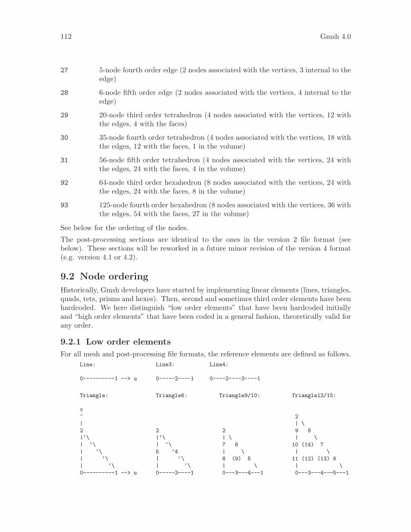
112 Gmsh 4.0
27 5-node fourth order edge (2 nodes associated with the vertices, 3 internal to theedge)
28 6-node fifth order edge (2 nodes associated with the vertices, 4 internal to theedge)
29 20-node third order tetrahedron (4 nodes associated with the vertices, 12 withthe edges, 4 with the faces)
30 35-node fourth order tetrahedron (4 nodes associated with the vertices, 18 withthe edges, 12 with the faces, 1 in the volume)
31 56-node fifth order tetrahedron (4 nodes associated with the vertices, 24 withthe edges, 24 with the faces, 4 in the volume)
92 64-node third order hexahedron (8 nodes associated with the vertices, 24 withthe edges, 24 with the faces, 8 in the volume)
93 125-node fourth order hexahedron (8 nodes associated with the vertices, 36 withthe edges, 54 with the faces, 27 in the volume)
See below for the ordering of the nodes.
The post-processing sections are identical to the ones in the version 2 file format (seebelow). These sections will be reworked in a future minor revision of the version 4 format(e.g. version 4.1 or 4.2).
9.2 Node ordering
Historically, Gmsh developers have started by implementing linear elements (lines, triangles,quads, tets, prisms and hexes). Then, second and sometimes third order elements have beenhardcoded. We here distinguish “low order elements” that have been hardcoded initiallyand “high order elements” that have been coded in a general fashion, theoretically valid forany order.
9.2.1 Low order elements
For all mesh and post-processing file formats, the reference elements are defined as follows.
Line: Line3: Line4:
0----------1 --> u 0-----2----1 0----2----3----1
Triangle: Triangle6: Triangle9/10: Triangle12/15:
v
^ 2
| | \
2 2 2 9 8
|‘\ |‘\ | \ | \
| ‘\ | ‘\ 7 6 10 (14) 7
| ‘\ 5 ‘4 | \ | \
| ‘\ | ‘\ 8 (9) 5 11 (12) (13) 6
| ‘\ | ‘\ | \ | \
0----------1 --> u 0-----3----1 0---3---4---1 0---3---4---5---1

Chapter 9: File formats 113
Quadrangle: Quadrangle8: Quadrangle9:
v
^
|
3-----------2 3-----6-----2 3-----6-----2
| | | | | | |
| | | | | | |
| +---- | --> u 7 5 7 8 5
| | | | | |
| | | | | |
0-----------1 0-----4-----1 0-----4-----1
Tetrahedron: Tetrahedron10:
v
.
,/
/
2 2
,/|‘\ ,/|‘\
,/ | ‘\ ,/ | ‘\
,/ ’. ‘\ ,6 ’. ‘5
,/ | ‘\ ,/ 8 ‘\
,/ | ‘\ ,/ | ‘\
0-----------’.--------1 --> u 0--------4--’.--------1
‘\. | ,/ ‘\. | ,/
‘\. | ,/ ‘\. | ,9
‘\. ’. ,/ ‘7. ’. ,/
‘\. |/ ‘\. |/
‘3 ‘3
‘\.
‘ w
Hexahedron: Hexahedron20: Hexahedron27:
v
3----------2 3----13----2 3----13----2
|\ ^ |\ |\ |\ |\ |\
| \ | | \ | 15 | 14 |15 24 | 14
| \ | | \ 9 \ 11 \ 9 \ 20 11 \
| 7------+---6 | 7----19+---6 | 7----19+---6
| | +-- |-- | -> u | | | | |22 | 26 | 23|
0---+---\--1 | 0---+-8----1 | 0---+-8----1 |
\ | \ \ | \ 17 \ 18 \ 17 25 \ 18
\ | \ \ | 10 | 12| 10 | 21 12|
\| w \| \| \| \| \|
4----------5 4----16----5 4----16----5

114 Gmsh 4.0
Prism: Prism15: Prism18:
w
^
|
3 3 3
,/|‘\ ,/|‘\ ,/|‘\
,/ | ‘\ 12 | 13 12 | 13
,/ | ‘\ ,/ | ‘\ ,/ | ‘\
4------+------5 4------14-----5 4------14-----5
| | | | 8 | | 8 |
| ,/|‘\ | | | | | ,/|‘\ |
| ,/ | ‘\ | | | | | 15 | 16 |
|,/ | ‘\| | | | |,/ | ‘\|
,| | |\ 10 | 11 10-----17-----11
,/ | 0 | ‘\ | 0 | | 0 |
u | ,/ ‘\ | v | ,/ ‘\ | | ,/ ‘\ |
| ,/ ‘\ | | ,6 ‘7 | | ,6 ‘7 |
|,/ ‘\| |,/ ‘\| |,/ ‘\|
1-------------2 1------9------2 1------9------2
Pyramid: Pyramid13: Pyramid14:
4 4 4
,/|\ ,/|\ ,/|\
,/ .’|\ ,/ .’|\ ,/ .’|\
,/ | | \ ,/ | | \ ,/ | | \
,/ .’ | ‘. ,/ .’ | ‘. ,/ .’ | ‘.
,/ | ’. \ ,7 | 12 \ ,7 | 12 \
,/ .’ w | \ ,/ .’ | \ ,/ .’ | \
,/ | ^ | \ ,/ 9 | 11 ,/ 9 | 11
0----------.’--|-3 ‘. 0--------6-.’----3 ‘. 0--------6-.’----3 ‘.
‘\ | | ‘\ \ ‘\ | ‘\ \ ‘\ | ‘\ \
‘\ .’ +----‘\ - \ -> v ‘5 .’ 10 \ ‘5 .’ 13 10 \
‘\ | ‘\ ‘\ \ ‘\ | ‘\ \ ‘\ | ‘\ \
‘\.’ ‘\ ‘\‘ ‘\.’ ‘\‘ ‘\.’ ‘\‘
1----------------2 1--------8-------2 1--------8-------2
‘\
u
9.2.2 High order elements
The node ordering of a higher order (possibly curved) element is compatible with the num-bering of low order element (it is a generalization). We number nodes in the followingorder:
– the element principal or corner vertices;
– the internal nodes for each edge;
– the internal nodes for each face;
– the volume internal nodes.
The numbering for internal nodes is recursive, i.e. the numbering follows that of the nodesof an embedded edge/face/volume of lower order. The higher order nodes are assumedto be equispaced. Edges and faces are numbered following the lowest order template thatgenerates a single high-order on this edge/face. Furthermore, an edge is oriented from

Chapter 9: File formats 115
the node with the lowest to the highest index. The orientation of a face is such that thecomputed normal points outward; the starting point is the node with the lowest index.
9.3 Legacy formats
This section describes Gmsh’s older native file formats. Future versions of Gmsh will con-tinue to support these formats, but we recommend that you do not use them in new appli-cations.
9.3.1 MSH file format version 2
The MSH file format version 2 is Gmsh’s previous native mesh file format, now supersededby the format described in Section 9.1 [MSH file format (version 4)], page 107. It is definedas follows:
The format is defined as follows:
$MeshFormat
version-number file-type data-size
$EndMeshFormat
$PhysicalNames
number-of-names
physical-dimension physical-tag "physical-name"
...
$EndPhysicalNames
$Nodes
number-of-nodes
node-number x-coord y-coord z-coord
...
$EndNodes
$Elements
number-of-elements
elm-number elm-type number-of-tags < tag > ... node-number-list
...
$EndElements
$Periodic
number-of-periodic-entities
dimension slave-entity-tag master-entity-tag
number-of-nodes
slave-node-number master-node-number
...
$EndPeriodic
$NodeData
number-of-string-tags
< "string-tag" >
...
number-of-real-tags
< real-tag >
...
number-of-integer-tags

116 Gmsh 4.0
< integer-tag >
...
node-number value ...
...
$EndNodeData
$ElementData
number-of-string-tags
< "string-tag" >
...
number-of-real-tags
< real-tag >
...
number-of-integer-tags
< integer-tag >
...
elm-number value ...
...
$EndElementData
$ElementNodeData
number-of-string-tags
< "string-tag" >
...
number-of-real-tags
< real-tag >
...
number-of-integer-tags
< integer-tag >
...
elm-number number-of-nodes-per-element value ...
...
$EndElementNodeData
$InterpolationScheme
"name"
number-of-element-topologies
elm-topology
number-of-interpolation-matrices
num-rows num-columns value ...
...
$EndInterpolationScheme
where
version-number
is a real number equal to 2.2
file-type
is an integer equal to 0 in the ASCII file format.
Chapter 9: File formats 117
data-size
is an integer equal to the size of the floating point numbers used in the file(currently only data-size = sizeof(double) is supported).
number-of-nodes
is the number of nodes in the mesh.
node-number
is the number (index) of the n-th node in the mesh; node-number must be apostive (non-zero) integer. Note that the node-numbers do not necessarily haveto form a dense nor an ordered sequence.
x-coord y-coord z-coord
are the floating point values giving the X, Y and Z coordinates of the n-th node.
number-of-elements
is the number of elements in the mesh.
elm-number
is the number (index) of the n-th element in the mesh; elm-number must be apostive (non-zero) integer. Note that the elm-numbers do not necessarily haveto form a dense nor an ordered sequence.
elm-type defines the geometrical type of the n-th element: see Section 9.1 [MSH fileformat (version 4)], page 107.
number-of-tags
gives the number of integer tags that follow for the n-th element. By default, thefirst tag is the tag of the physical entity to which the element belongs; the secondis the tag of the elementary geometrical entity to which the element belongs; thethird is the number of mesh partitions to which the element belongs, followedby the partition ids (negative partition ids indicate ghost cells). A zero tag isequivalent to no tag. Gmsh and most codes using the MSH 2 format require atleast the first two tags (physical and elementary tags).
node-number-list
is the list of the node numbers of the n-th element. The ordering of the nodesis given in Section 9.2 [Node ordering], page 112.
number-of-string-tags
gives the number of string tags that follow. By default the first string-tagis interpreted as the name of the post-processing view and the second as thename of the interpolation scheme. The interpolation scheme is provided in the$InterpolationScheme section (see below).
number-of-real-tags
gives the number of real number tags that follow. By default the first real-tagis interpreted as a time value associated with the dataset.
number-of-integer-tags
gives the number of integer tags that follow. By default the first integer-tag isinterpreted as a time step index (starting at 0), the second as the number offield components of the data in the view (1, 3 or 9), the third as the number of
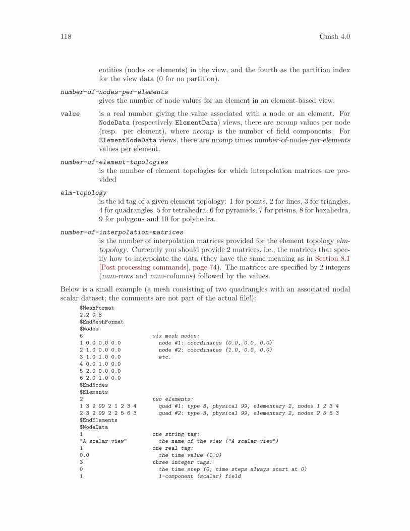
118 Gmsh 4.0
entities (nodes or elements) in the view, and the fourth as the partition indexfor the view data (0 for no partition).
number-of-nodes-per-elements
gives the number of node values for an element in an element-based view.
value is a real number giving the value associated with a node or an element. ForNodeData (respectively ElementData) views, there are ncomp values per node(resp. per element), where ncomp is the number of field components. ForElementNodeData views, there are ncomp times number-of-nodes-per-elementsvalues per element.
number-of-element-topologies
is the number of element topologies for which interpolation matrices are pro-vided
elm-topology
is the id tag of a given element topology: 1 for points, 2 for lines, 3 for triangles,4 for quadrangles, 5 for tetrahedra, 6 for pyramids, 7 for prisms, 8 for hexahedra,9 for polygons and 10 for polyhedra.
number-of-interpolation-matrices
is the number of interpolation matrices provided for the element topology elm-topology. Currently you should provide 2 matrices, i.e., the matrices that spec-ify how to interpolate the data (they have the same meaning as in Section 8.1[Post-processing commands], page 74). The matrices are specified by 2 integers(num-rows and num-columns) followed by the values.
Below is a small example (a mesh consisting of two quadrangles with an associated nodalscalar dataset; the comments are not part of the actual file!):
$MeshFormat
2.2 0 8
$EndMeshFormat
$Nodes
6 six mesh nodes:
1 0.0 0.0 0.0 node #1: coordinates (0.0, 0.0, 0.0)
2 1.0 0.0 0.0 node #2: coordinates (1.0, 0.0, 0.0)
3 1.0 1.0 0.0 etc.
4 0.0 1.0 0.0
5 2.0 0.0 0.0
6 2.0 1.0 0.0
$EndNodes
$Elements
2 two elements:
1 3 2 99 2 1 2 3 4 quad #1: type 3, physical 99, elementary 2, nodes 1 2 3 4
2 3 2 99 2 2 5 6 3 quad #2: type 3, physical 99, elementary 2, nodes 2 5 6 3
$EndElements
$NodeData
1 one string tag:
"A scalar view" the name of the view ("A scalar view")
1 one real tag:
0.0 the time value (0.0)
3 three integer tags:
0 the time step (0; time steps always start at 0)
1 1-component (scalar) field

Chapter 9: File formats 119
6 six associated nodal values
1 0.0 value associated with node #1 (0.0)
2 0.1 value associated with node #2 (0.1)
3 0.2 etc.
4 0.0
5 0.2
6 0.4
$EndNodeData
The binary file format is similar to the ASCII format described above:
$MeshFormat
version-number file-type data-size
one-binary
$EndMeshFormat
$Nodes
number-of-nodes
nodes-binary
$EndNodes
$Elements
number-of-elements
element-header-binary
elements-binary
element-header-binary
elements-binary
...
$EndElements
[ All other sections are identical to ASCII, except that node-number,
elm-number, number-of-nodes-per-element and values are written in
binary format. Beware that all the $End tags must start on a new line. ]
where
version-number
is a real number equal to 2.2.
file-type
is an integer equal to 1.
data-size
has the same meaning as in the ASCII file format. Currently only data-size =sizeof(double) is supported.
one-binary
is an integer of value 1 written in binary form. This integer is used for detectingif the computer on which the binary file was written and the computer on whichthe file is read are of the same type (little or big endian).
Here is a pseudo C code to write one-binary :
int one = 1;
fwrite(&one, sizeof(int), 1, file);
number-of-nodes
has the same meaning as in the ASCII file format.

120 Gmsh 4.0
nodes-binary
is the list of nodes in binary form, i.e., a array of number-of-nodes * (4 + 3 *data-size) bytes. For each node, the first 4 bytes contain the node number andthe next (3 * data-size) bytes contain the three floating point coordinates.
Here is a pseudo C code to write nodes-binary :
for(i = 0; i < number_of_nodes; i++){
fwrite(&num_i, sizeof(int), 1, file);
double xyz[3] = {node_i_x, node_i_y, node_i_z};
fwrite(xyz, sizeof(double), 3, file);
}
number-of-elements
has the same meaning as in the ASCII file format.
element-header-binary
is a list of 3 integers in binary form, i.e., an array of (3 * 4) bytes: the firstfour bytes contain the type of the elements that follow (same as elm-type in theASCII format), the next four contain the number of elements that follow, andthe last four contain the number of tags per element (same as number-of-tagsin the ASCII format).
Here is a pseudo C code to write element-header-binary :
int header[3] = {elm_type, num_elm_follow, num_tags};
fwrite(header, sizeof(int), 3, file);
elements-binary
is a list of elements in binary form, i.e., an array of “number of elements thatfollow” * (4 + number-of-tags * 4 + #node-number-list * 4) bytes. For eachelement, the first four bytes contain the element number, the next (number-of-tags * 4) contain the tags, and the last (#node-number-list * 4) contain thenode indices.
Here is a pseudo C code to write elements-binary for triangles with the 2 stan-dard tags (the physical and elementary regions):
for(i = 0; i < number_of_triangles; i++){
int data[6] = {num_i, physical, elementary,
node_i_1, node_i_2, node_i_3};
fwrite(data, sizeof(int), 6, file);
}
9.3.2 MSH file format version 1
The MSH file format version 1 is Gmsh’s original native mesh file format, now supersededby the format described in Section 9.1 [MSH file format (version 4)], page 107. It is definedas follows:
$NOD
number-of-nodes
node-number x-coord y-coord z-coord
...
$ENDNOD

Chapter 9: File formats 121
$ELM
number-of-elements
elm-number elm-type reg-phys reg-elem number-of-nodes node-number-list
...
$ENDELM
where
number-of-nodes
is the number of nodes in the mesh.
node-number
is the number (index) of the n-th node in the mesh; node-number must be apostive (non-zero) integer. Note that the node-numbers do not necessarily haveto form a dense nor an ordered sequence.
x-coord y-coord z-coord
are the floating point values giving the X, Y and Z coordinates of the n-th node.
number-of-elements
is the number of elements in the mesh.
elm-number
is the number (index) of the n-th element in the mesh; elm-number must be apostive (non-zero) integer. Note that the elm-numbers do not necessarily haveto form a dense nor an ordered sequence.
elm-type defines the geometrical type of the n-th element:
1 2-node line.
2 3-node triangle.
3 4-node quadrangle.
4 4-node tetrahedron.
5 8-node hexahedron.
6 6-node prism.
7 5-node pyramid.
8 3-node second order line (2 nodes associated with the vertices and1 with the edge).
9 6-node second order triangle (3 nodes associated with the verticesand 3 with the edges).
10 9-node second order quadrangle (4 nodes associated with the ver-tices, 4 with the edges and 1 with the face).
11 10-node second order tetrahedron (4 nodes associated with the ver-tices and 6 with the edges).
12 27-node second order hexahedron (8 nodes associated with the ver-tices, 12 with the edges, 6 with the faces and 1 with the volume).

122 Gmsh 4.0
13 18-node second order prism (6 nodes associated with the vertices,9 with the edges and 3 with the quadrangular faces).
14 14-node second order pyramid (5 nodes associated with the vertices,8 with the edges and 1 with the quadrangular face).
15 1-node point.
16 8-node second order quadrangle (4 nodes associated with the ver-tices and 4 with the edges).
17 20-node second order hexahedron (8 nodes associated with the ver-tices and 12 with the edges).
18 15-node second order prism (6 nodes associated with the verticesand 9 with the edges).
19 13-node second order pyramid (5 nodes associated with the verticesand 8 with the edges).
See below for the ordering of the nodes.
reg-phys is the tag of the physical entity to which the element belongs; reg-phys must bea postive integer, or zero. If reg-phys is equal to zero, the element is considerednot to belong to any physical entity.
reg-elem is the tag of the elementary entity to which the element belongs; reg-elem mustbe a postive (non-zero) integer.
number-of-nodes
is the number of nodes for the n-th element. This is redundant, but kept forbackward compatibility.
node-number-list
is the list of the number-of-nodes node numbers of the n-th element. Theordering of the nodes is given in Section 9.2 [Node ordering], page 112.
9.3.3 POS ASCII file format (Legacy)
The POS ASCII file is Gmsh’s old native post-processing format, now superseded by theformat described in Section 9.1 [MSH file format (version 4)], page 107. It is defined asfollows:
$PostFormat
1.4 file-type data-size
$EndPostFormat
$View
view-name nb-time-steps
nb-scalar-points nb-vector-points nb-tensor-points
nb-scalar-lines nb-vector-lines nb-tensor-lines
nb-scalar-triangles nb-vector-triangles nb-tensor-triangles
nb-scalar-quadrangles nb-vector-quadrangles nb-tensor-quadrangles
nb-scalar-tetrahedra nb-vector-tetrahedra nb-tensor-tetrahedra
nb-scalar-hexahedra nb-vector-hexahedra nb-tensor-hexahedra
nb-scalar-prisms nb-vector-prisms nb-tensor-prisms

Chapter 9: File formats 123
nb-scalar-pyramids nb-vector-pyramids nb-tensor-pyramids
nb-scalar-lines2 nb-vector-lines2 nb-tensor-lines2
nb-scalar-triangles2 nb-vector-triangles2 nb-tensor-triangles2
nb-scalar-quadrangles2 nb-vector-quadrangles2 nb-tensor-quadrangles2
nb-scalar-tetrahedra2 nb-vector-tetrahedra2 nb-tensor-tetrahedra2
nb-scalar-hexahedra2 nb-vector-hexahedra2 nb-tensor-hexahedra2
nb-scalar-prisms2 nb-vector-prisms2 nb-tensor-prisms2
nb-scalar-pyramids2 nb-vector-pyramids2 nb-tensor-pyramids2
nb-text2d nb-text2d-chars nb-text3d nb-text3d-chars
time-step-values
< scalar-point-value > ... < vector-point-value > ...
< tensor-point-value > ...
< scalar-line-value > ... < vector-line-value > ...
< tensor-line-value > ...
< scalar-triangle-value > ... < vector-triangle-value > ...
< tensor-triangle-value > ...
< scalar-quadrangle-value > ... < vector-quadrangle-value > ...
< tensor-quadrangle-value > ...
< scalar-tetrahedron-value > ... < vector-tetrahedron-value > ...
< tensor-tetrahedron-value > ...
< scalar-hexahedron-value > ... < vector-hexahedron-value > ...
< tensor-hexahedron-value > ...
< scalar-prism-value > ... < vector-prism-value > ...
< tensor-prism-value > ...
< scalar-pyramid-value > ... < vector-pyramid-value > ...
< tensor-pyramid-value > ...
< scalar-line2-value > ... < vector-line2-value > ...
< tensor-line2-value > ...
< scalar-triangle2-value > ... < vector-triangle2-value > ...
< tensor-triangle2-value > ...
< scalar-quadrangle2-value > ... < vector-quadrangle2-value > ...
< tensor-quadrangle2-value > ...
< scalar-tetrahedron2-value > ... < vector-tetrahedron2-value > ...
< tensor-tetrahedron2-value > ...
< scalar-hexahedron2-value > ... < vector-hexahedron2-value > ...
< tensor-hexahedron2-value > ...
< scalar-prism2-value > ... < vector-prism2-value > ...
< tensor-prism2-value > ...
< scalar-pyramid2-value > ... < vector-pyramid2-value > ...
< tensor-pyramid2-value > ...
< text2d > ... < text2d-chars > ...
< text3d > ... < text3d-chars > ...
$EndView
where
file-type
is an integer equal to 0 in the ASCII file format.

124 Gmsh 4.0
data-size
is an integer equal to the size of the floating point numbers used in the file(usually, data-size = sizeof(double)).
view-name
is a string containing the name of the view (max. 256 characters).
nb-time-steps
is an integer giving the number of time steps in the view.
nb-scalar-points
nb-vector-points
... are integers giving the number of scalar points, vector points, . . . , in the view.
nb-text2d
nb-text3d
are integers giving the number of 2D and 3D text strings in the view.
nb-text2d-chars
nb-text3d-chars
are integers giving the total number of characters in the 2D and 3D strings.
time-step-values
is a list of nb-time-steps double precision numbers giving the value of the time(or any other variable) for which an evolution was saved.
scalar-point-value
vector-point-value
... are lists of double precision numbers giving the node coordinates and the valuesassociated with the nodes of the nb-scalar-points scalar points, nb-vector-pointsvector points, . . . , for each of the time-step-values.
For example, vector-triangle-value is defined as:
coord1-node1 coord1-node2 coord1-node3
coord2-node1 coord2-node2 coord2-node3
coord3-node1 coord3-node2 coord3-node3
comp1-node1-time1 comp2-node1-time1 comp3-node1-time1
comp1-node2-time1 comp2-node2-time1 comp3-node2-time1
comp1-node3-time1 comp2-node3-time1 comp3-node3-time1
comp1-node1-time2 comp2-node1-time2 comp3-node1-time2
comp1-node2-time2 comp2-node2-time2 comp3-node2-time2
comp1-node3-time2 comp2-node3-time2 comp3-node3-time2
...
The ordering of the nodes is given in Section 9.2 [Node ordering], page 112.
text2d is a list of 4 double precision numbers:
coord1 coord2 style index
where coord1 and coord2 give the X-Y position of the 2D string in screen co-ordinates (measured from the top-left corner of the window) and where indexgives the starting index of the string in text2d-chars. If coord1 (respectivelycoord2) is negative, the position is measured from the right (respectively bot-tom) edge of the window. If coord1 (respectively coord2) is larger than 99999,

Chapter 9: File formats 125
the string is centered horizontally (respectively vertically). If style is equal tozero, the text is aligned bottom-left and displayed using the default font andsize. Otherwise, style is converted into an integer whose eight lower bits givethe font size, whose eight next bits select the font (the index corresponds tothe position in the font menu in the GUI), and whose eight next bits define thetext alignment (0=bottom-left, 1=bottom-center, 2=bottom-right, 3=top-left,4=top-center, 5=top-right, 6=center-left, 7=center-center, 8=center-right).
text2d-chars
is a list of nb-text2d-chars characters. Substrings are separated with the null‘\0’ character.
text3d is a list of 5 double precision numbers
coord1 coord2 coord3 style index
where coord1, coord2 and coord3 give the XYZ coordinates of the string inmodel (real world) coordinates, index gives the starting index of the string intext3d-chars, and style has the same meaning as in text2d.
text3d-chars
is a list of nb-text3d-chars chars. Substrings are separated with the null ‘\0’character.
9.3.4 POS binary file format (Legacy)
The POS binary file format is the same as the POS ASCII file format described inSection 9.3.3 [POS ASCII file format], page 122, except that:
1. file-type equals 1.
2. all lists of floating point numbers and characters are written in binary format
3. there is an additional integer, of value 1, written before time-step-values. This integeris used for detecting if the computer on which the binary file was written and thecomputer on which the file is read are of the same type (little or big endian).
Here is a pseudo C code to write a post-processing file in binary format:
int one = 1;
fprintf(file, "$PostFormat\n");
fprintf(file, "%g %d %d\n", 1.4, 1, sizeof(double));
fprintf(file, "$EndPostFormat\n");
fprintf(file, "$View\n");
fprintf(file, "%s %d "
"%d %d %d %d %d %d %d %d %d "
"%d %d %d %d %d %d %d %d %d "
"%d %d %d %d %d %d %d %d %d "
"%d %d %d %d %d %d %d %d %d "
"%d %d %d %d %d %d %d %d %d "
"%d %d %d %d\n",
view-name, nb-time-steps,
nb-scalar-points, nb-vector-points, nb-tensor-points,
nb-scalar-lines, nb-vector-lines, nb-tensor-lines,
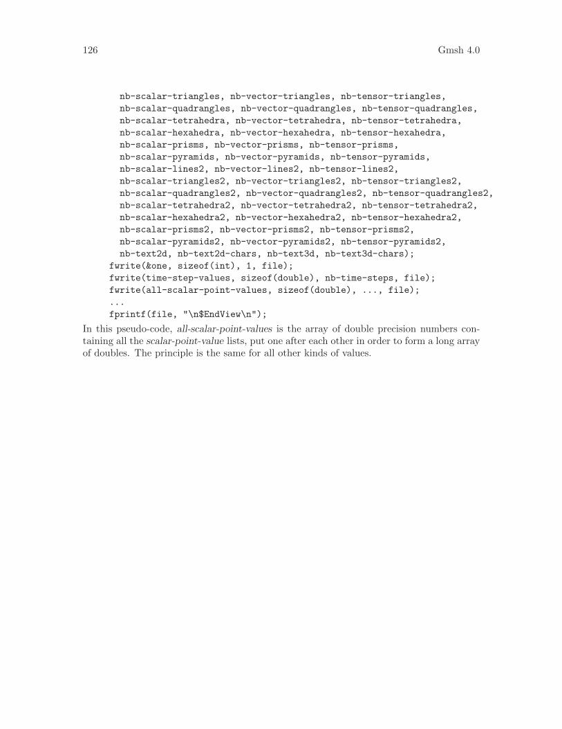
126 Gmsh 4.0
nb-scalar-triangles, nb-vector-triangles, nb-tensor-triangles,
nb-scalar-quadrangles, nb-vector-quadrangles, nb-tensor-quadrangles,
nb-scalar-tetrahedra, nb-vector-tetrahedra, nb-tensor-tetrahedra,
nb-scalar-hexahedra, nb-vector-hexahedra, nb-tensor-hexahedra,
nb-scalar-prisms, nb-vector-prisms, nb-tensor-prisms,
nb-scalar-pyramids, nb-vector-pyramids, nb-tensor-pyramids,
nb-scalar-lines2, nb-vector-lines2, nb-tensor-lines2,
nb-scalar-triangles2, nb-vector-triangles2, nb-tensor-triangles2,
nb-scalar-quadrangles2, nb-vector-quadrangles2, nb-tensor-quadrangles2,
nb-scalar-tetrahedra2, nb-vector-tetrahedra2, nb-tensor-tetrahedra2,
nb-scalar-hexahedra2, nb-vector-hexahedra2, nb-tensor-hexahedra2,
nb-scalar-prisms2, nb-vector-prisms2, nb-tensor-prisms2,
nb-scalar-pyramids2, nb-vector-pyramids2, nb-tensor-pyramids2,
nb-text2d, nb-text2d-chars, nb-text3d, nb-text3d-chars);
fwrite(&one, sizeof(int), 1, file);
fwrite(time-step-values, sizeof(double), nb-time-steps, file);
fwrite(all-scalar-point-values, sizeof(double), ..., file);
...
fprintf(file, "\n$EndView\n");
In this pseudo-code, all-scalar-point-values is the array of double precision numbers con-taining all the scalar-point-value lists, put one after each other in order to form a long arrayof doubles. The principle is the same for all other kinds of values.
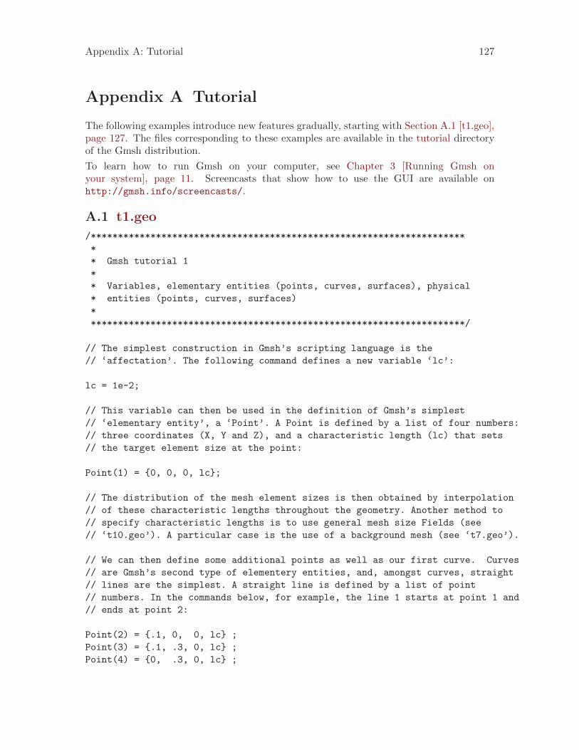
Appendix A: Tutorial 127
Appendix A Tutorial
The following examples introduce new features gradually, starting with Section A.1 [t1.geo],page 127. The files corresponding to these examples are available in the tutorial directoryof the Gmsh distribution.
To learn how to run Gmsh on your computer, see Chapter 3 [Running Gmsh onyour system], page 11. Screencasts that show how to use the GUI are available onhttp://gmsh.info/screencasts/.
A.1 t1.geo
/*********************************************************************
*
* Gmsh tutorial 1
*
* Variables, elementary entities (points, curves, surfaces), physical
* entities (points, curves, surfaces)
*
*********************************************************************/
// The simplest construction in Gmsh’s scripting language is the
// ‘affectation’. The following command defines a new variable ‘lc’:
lc = 1e-2;
// This variable can then be used in the definition of Gmsh’s simplest
// ‘elementary entity’, a ‘Point’. A Point is defined by a list of four numbers:
// three coordinates (X, Y and Z), and a characteristic length (lc) that sets
// the target element size at the point:
Point(1) = {0, 0, 0, lc};
// The distribution of the mesh element sizes is then obtained by interpolation
// of these characteristic lengths throughout the geometry. Another method to
// specify characteristic lengths is to use general mesh size Fields (see
// ‘t10.geo’). A particular case is the use of a background mesh (see ‘t7.geo’).
// We can then define some additional points as well as our first curve. Curves
// are Gmsh’s second type of elementery entities, and, amongst curves, straight
// lines are the simplest. A straight line is defined by a list of point
// numbers. In the commands below, for example, the line 1 starts at point 1 and
// ends at point 2:
Point(2) = {.1, 0, 0, lc} ;
Point(3) = {.1, .3, 0, lc} ;
Point(4) = {0, .3, 0, lc} ;

128 Gmsh 4.0
Line(1) = {1,2} ;
Line(2) = {3,2} ;
Line(3) = {3,4} ;
Line(4) = {4,1} ;
// The third elementary entity is the surface. In order to define a simple
// rectangular surface from the four curves defined above, a curve loop has first
// to be defined. A curve loop is a list of connected curves, a sign being
// associated with each curve (depending on the orientation of the curve):
Curve Loop(1) = {4,1,-2,3} ;
// We can then define the surface as a list of curve loops (only one here, since
// there are no holes--see ‘t4.geo’):
Plane Surface(1) = {1} ;
// At this level, Gmsh knows everything to display the rectangular surface 6 and
// to mesh it. An optional step is needed if we want to group elementary
// geometrical entities into more meaningful groups, e.g. to define some
// mathematical ("domain", "boundary"), functional ("left wing", "fuselage") or
// material ("steel", "carbon") properties.
//
// Such groups are called "Physical Groups" in Gmsh. By default, if physical
// groups are defined, Gmsh will export in output files only those elements that
// belong to at least one physical group. (To force Gmsh to save all elements,
// whether they belong to physical groups or not, set "Mesh.SaveAll=1;", or
// specify "-save_all" on the command line.)
//
// Here we define a physical curve that groups the left, bottom and right lines
// in a single group (with prescribed tag 5); and a physical surface with name
// "My surface" (with an automatic tag) containg the geometrical surface 1:
Physical Curve(5) = {1, 2, 4} ;
Physical Surface("My surface") = {1} ;
// Note that starting with Gmsh 3.0, models can be built using different
// geometry kernels than the default "built-in" kernel. By specifying
//
// SetFactory("OpenCASCADE");
//
// any subsequent command in the .geo file would be handled by the OpenCASCADE
// geometry kernel instead of the built-in kernel. A rectangular surface could
// then simply be created with
//
// Rectangle(2) = {.2, 0, 0, 0.1, 0.3};
//

Appendix A: Tutorial 129
// See tutorial/t16.geo for a complete example, and demos/boolean for more.
A.2 t2.geo
/*********************************************************************
*
* Gmsh tutorial 2
*
* Includes, geometrical transformations, extruded geometries,
* elementary entities (volumes), physical entities (volumes)
*
*********************************************************************/
// We first include the previous tutorial file, in order to use it as a basis
// for this one:
Include "t1.geo";
// We can then add new points and curves in the same way as we did in ‘t1.geo’:
Point(5) = {0, .4, 0, lc};
Line(5) = {4, 5};
// But Gmsh also provides tools to tranform (translate, rotate, etc.)
// elementary entities or copies of elementary entities. For example, the point
// 3 can be moved by 0.05 units to the left with:
Translate {-0.05, 0, 0} { Point{3}; }
// The resulting point can also be duplicated and translated by 0.1 along the y
// axis:
Translate {0, 0.1, 0} { Duplicata{ Point{3}; } }
// This command created a new point with an automatically assigned id. This id
// can be obtained using the graphical user interface by hovering the mouse over
// it and looking at the bottom of the graphic window: in this case, the new
// point has id "6". Point 6 can then be used to create new entities, e.g.:
Line(7) = {3, 6};
Line(8) = {6, 5};
Curve Loop(10) = {5,-8,-7,3};
Plane Surface(11) = {10};
// Using the graphical user interface to obtain the ids of newly created
// entities can sometimes be cumbersome. It can then be advantageous to use the
// return value of the transformation commands directly. For example, the
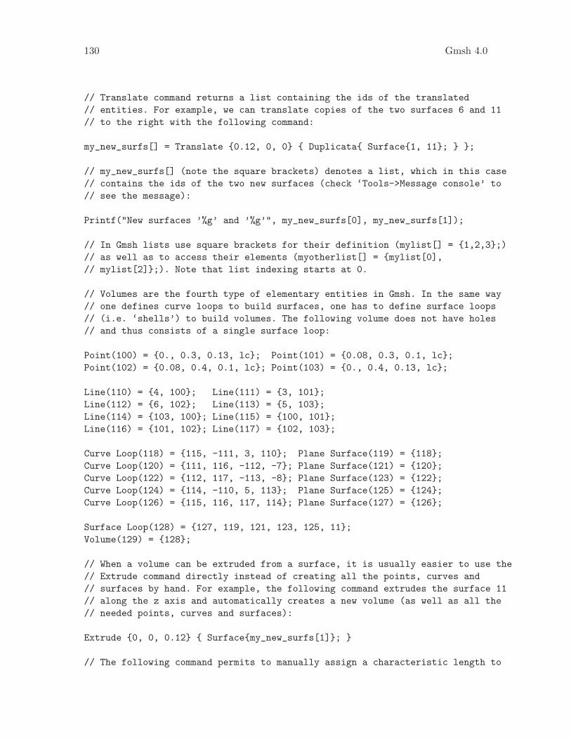
130 Gmsh 4.0
// Translate command returns a list containing the ids of the translated
// entities. For example, we can translate copies of the two surfaces 6 and 11
// to the right with the following command:
my_new_surfs[] = Translate {0.12, 0, 0} { Duplicata{ Surface{1, 11}; } };
// my_new_surfs[] (note the square brackets) denotes a list, which in this case
// contains the ids of the two new surfaces (check ‘Tools->Message console’ to
// see the message):
Printf("New surfaces ’%g’ and ’%g’", my_new_surfs[0], my_new_surfs[1]);
// In Gmsh lists use square brackets for their definition (mylist[] = {1,2,3};)
// as well as to access their elements (myotherlist[] = {mylist[0],
// mylist[2]};). Note that list indexing starts at 0.
// Volumes are the fourth type of elementary entities in Gmsh. In the same way
// one defines curve loops to build surfaces, one has to define surface loops
// (i.e. ‘shells’) to build volumes. The following volume does not have holes
// and thus consists of a single surface loop:
Point(100) = {0., 0.3, 0.13, lc}; Point(101) = {0.08, 0.3, 0.1, lc};
Point(102) = {0.08, 0.4, 0.1, lc}; Point(103) = {0., 0.4, 0.13, lc};
Line(110) = {4, 100}; Line(111) = {3, 101};
Line(112) = {6, 102}; Line(113) = {5, 103};
Line(114) = {103, 100}; Line(115) = {100, 101};
Line(116) = {101, 102}; Line(117) = {102, 103};
Curve Loop(118) = {115, -111, 3, 110}; Plane Surface(119) = {118};
Curve Loop(120) = {111, 116, -112, -7}; Plane Surface(121) = {120};
Curve Loop(122) = {112, 117, -113, -8}; Plane Surface(123) = {122};
Curve Loop(124) = {114, -110, 5, 113}; Plane Surface(125) = {124};
Curve Loop(126) = {115, 116, 117, 114}; Plane Surface(127) = {126};
Surface Loop(128) = {127, 119, 121, 123, 125, 11};
Volume(129) = {128};
// When a volume can be extruded from a surface, it is usually easier to use the
// Extrude command directly instead of creating all the points, curves and
// surfaces by hand. For example, the following command extrudes the surface 11
// along the z axis and automatically creates a new volume (as well as all the
// needed points, curves and surfaces):
Extrude {0, 0, 0.12} { Surface{my_new_surfs[1]}; }
// The following command permits to manually assign a characteristic length to

Appendix A: Tutorial 131
// some of the new points:
Characteristic Length {103, 105, 109, 102, 28, 24, 6, 5} = lc * 3;
// Note that, if the transformation tools are handy to create complex
// geometries, it is also sometimes useful to generate the ‘flat’ geometry, with
// an explicit list of all elementary entities. This can be achieved by
// selecting the ‘File->Export->Gmsh unrolled geometry’ menu or by typing
//
// > gmsh t2.geo -0
//
// on the command line.
// We finally group volumes 129 and 130 in a single physical group with tag "1"
// and name "The volume":
Physical Volume("The volume", 1) = {129,130};
A.3 t3.geo
/*********************************************************************
*
* Gmsh tutorial 3
*
* Extruded meshes, parameters, options
*
*********************************************************************/
// Again, we start by including the first tutorial:
Include "t1.geo";
// As in ‘t2.geo’, we plan to perform an extrusion along the z axis. But here,
// instead of only extruding the geometry, we also want to extrude the 2D
// mesh. This is done with the same ‘Extrude’ command, but by specifying element
// ’Layers’ (2 layers in this case, the first one with 8 subdivisions and the
// second one with 2 subdivisions, both with a height of h/2):
h = 0.1;
Extrude {0,0,h} {
Surface{1}; Layers{ {8,2}, {0.5,1} };
}
// The extrusion can also be performed with a rotation instead of a translation,
// and the resulting mesh can be recombined into prisms (we use only one layer
// here, with 7 subdivisions). All rotations are specified by an axis direction

132 Gmsh 4.0
// ({0,1,0}), an axis point ({-0.1,0,0.1}) and a rotation angle (-Pi/2):
Extrude { {0,1,0} , {-0.1,0,0.1} , -Pi/2 } {
Surface{28}; Layers{7}; Recombine;
}
// Note that a translation ({-2*h,0,0}) and a rotation ({1,0,0}, {0,0.15,0.25},
// Pi/2) can also be combined. Here the angle is specified as a ’parameter’,
// using the ’DefineConstant’ syntax. This parameter can be modified
// insteractively in the GUI, and can be exchanged with other codes using the
// ONELAB framework:
DefineConstant[ angle = {90, Min 0, Max 120, Step 1,
Name "Parameters/Twisting angle"} ];
out[] = Extrude { {-2*h,0,0}, {1,0,0} , {0,0.15,0.25} , angle * Pi / 180 } {
Surface{50}; Layers{10}; Recombine;
};
// In this last extrusion command we retrieved the volume number programatically
// by using the return value (a list) of the Extrude command. This list contains
// the "top" of the extruded surface (in out[0]), the newly created volume (in
// out[1]) and the ids of the lateral surfaces (in out[2], out[3], ...)
// We can then define a new physical volume (with tag 101) to group all the
// elementary volumes:
Physical Volume(101) = {1, 2, out[1]};
// Let us now change some options... Since all interactive options are
// accessible in Gmsh’s scripting language, we can for example make point tags
// visible or redefine some colors directly in the input file:
Geometry.PointNumbers = 1;
Geometry.Color.Points = Orange;
General.Color.Text = White;
Mesh.Color.Points = {255,0,0};
// Note that all colors can be defined literally or numerically, i.e.
// ‘Mesh.Color.Points = Red’ is equivalent to ‘Mesh.Color.Points = {255,0,0}’;
// and also note that, as with user-defined variables, the options can be used
// either as right or left hand sides, so that the following command will set
// the surface color to the same color as the points:
Geometry.Color.Surfaces = Geometry.Color.Points;
// You can use the ‘Help->Current options’ menu to see the current values of all

Appendix A: Tutorial 133
// options. To save all the options in a file, use ‘File->Export->Gmsh
// options’. To associate the current options with the current file use
// ‘File->Save Options->For Current File’. To save the current options for all
// future Gmsh sessions use ‘File->Save Options->As default’.
A.4 t4.geo
/*********************************************************************
*
* Gmsh tutorial 4
*
* Built-in functions, surface holes, annotations, mesh colors
*
*********************************************************************/
// As usual, we start by defining some variables:
cm = 1e-02;
e1 = 4.5 * cm; e2 = 6 * cm / 2; e3 = 5 * cm / 2;
h1 = 5 * cm; h2 = 10 * cm; h3 = 5 * cm; h4 = 2 * cm; h5 = 4.5 * cm;
R1 = 1 * cm; R2 = 1.5 * cm; r = 1 * cm;
Lc1 = 0.01;
Lc2 = 0.003;
// We can use all the usual mathematical functions (note the capitalized first
// letters), plus some useful functions like Hypot(a, b) := Sqrt(a^2 + b^2):
ccos = (-h5*R1 + e2 * Hypot(h5, Hypot(e2, R1))) / (h5^2 + e2^2);
ssin = Sqrt(1 - ccos^2);
// Then we define some points and some lines using these variables:
Point(1) = {-e1-e2, 0 , 0, Lc1}; Point(2) = {-e1-e2, h1 , 0, Lc1};
Point(3) = {-e3-r , h1 , 0, Lc2}; Point(4) = {-e3-r , h1+r , 0, Lc2};
Point(5) = {-e3 , h1+r , 0, Lc2}; Point(6) = {-e3 , h1+h2, 0, Lc1};
Point(7) = { e3 , h1+h2, 0, Lc1}; Point(8) = { e3 , h1+r , 0, Lc2};
Point(9) = { e3+r , h1+r , 0, Lc2}; Point(10)= { e3+r , h1 , 0, Lc2};
Point(11)= { e1+e2, h1 , 0, Lc1}; Point(12)= { e1+e2, 0 , 0, Lc1};
Point(13)= { e2 , 0 , 0, Lc1};
Point(14)= { R1 / ssin, h5+R1*ccos, 0, Lc2};
Point(15)= { 0 , h5 , 0, Lc2};
Point(16)= {-R1 / ssin, h5+R1*ccos, 0, Lc2};
Point(17)= {-e2 , 0.0 , 0, Lc1};
Point(18)= {-R2 , h1+h3 , 0, Lc2}; Point(19)= {-R2 , h1+h3+h4, 0, Lc2};
Point(20)= { 0 , h1+h3+h4, 0, Lc2}; Point(21)= { R2 , h1+h3+h4, 0, Lc2};

134 Gmsh 4.0
Point(22)= { R2 , h1+h3 , 0, Lc2}; Point(23)= { 0 , h1+h3 , 0, Lc2};
Point(24)= { 0, h1+h3+h4+R2, 0, Lc2}; Point(25)= { 0, h1+h3-R2, 0, Lc2};
Line(1) = {1 , 17};
Line(2) = {17, 16};
// Gmsh provides other curve primitives than straight lines: splines, B-splines,
// circle arcs, ellipse arcs, etc. Here we define a new circle arc, starting at
// point 14 and ending at point 16, with the circle’s center being the point 15:
Circle(3) = {14,15,16};
// Note that, in Gmsh, circle arcs should always be smaller than Pi. We can then
// define additional lines and circles, as well as a new surface:
Line(4) = {14,13}; Line(5) = {13,12}; Line(6) = {12,11};
Line(7) = {11,10}; Circle(8) = {8,9,10}; Line(9) = {8,7};
Line(10) = {7,6}; Line(11) = {6,5}; Circle(12) = {3,4,5};
Line(13) = {3,2}; Line(14) = {2,1}; Line(15) = {18,19};
Circle(16) = {21,20,24}; Circle(17) = {24,20,19};
Circle(18) = {18,23,25}; Circle(19) = {25,23,22};
Line(20) = {21,22};
Curve Loop(21) = {17,-15,18,19,-20,16};
Plane Surface(22) = {21};
// But we still need to define the exterior surface. Since this surface has a
// hole, its definition now requires two curves loops:
Curve Loop(23) = {11,-12,13,14,1,2,-3,4,5,6,7,-8,9,10};
Plane Surface(24) = {23,21};
// As a general rule, if a surface has N holes, it is defined by N+1 curve loops:
// the first loop defines the exterior boundary; the other loops define the
// boundaries of the holes.
// Finally, we can add some comments by embedding a post-processing view
// containing some strings:
View "comments" {
// Add a text string in window coordinates, 10 pixels from the left and 10
// pixels from the bottom, using the StrCat function to concatenate strings:
T2(10, -10, 0){ StrCat("Created on ", Today, " with Gmsh") };
// Add a text string in model coordinates centered at (X,Y,Z) = (0, 0.11, 0):
T3(0, 0.11, 0, TextAttributes("Align", "Center", "Font", "Helvetica")){ "Hole" };
Appendix A: Tutorial 135
// If a string starts with ‘file://’, the rest is interpreted as an image
// file. For 3D annotations, the size in model coordinates can be specified
// after a ‘@’ symbol in the form ‘widthxheight’ (if one of ‘width’ or
// ‘height’ is zero, natural scaling is used; if both are zero, original image
// dimensions in pixels are used):
T3(0, 0.09, 0, TextAttributes("Align", "Center")){ "file://[email protected]" };
// The 3D orientation of the image can be specified by proving the direction
// of the bottom and left edge of the image in model space:
T3(-0.01, 0.09, 0, 0){ "file://[email protected],0,0,1,0,1,0" };
// The image can also be drawn in "billboard" mode, i.e. always parallel to
// the camera, by using the ‘#’ symbol:
T3(0, 0.12, 0, TextAttributes("Align", "Center")){ "file://[email protected]#" };
// The size of 2D annotations is given directly in pixels:
T2(350, -7, 0){ "file://image.png@20x0" };
};
// Views and geometrical entities can be made to respond to double-click events:
View[0].DoubleClickedCommand = "Printf(’View[0] has been double-clicked!’);";
Geometry.DoubleClickedLineCommand = "Printf(’Curve %g has been double-clicked!’,
Geometry.DoubleClickedEntityTag);";
// We can also change the color of some mesh entities:
Color Grey50{ Surface{ 22 }; }
Color Purple{ Surface{ 24 }; }
Color Red{ Curve{ 1:14 }; }
Color Yellow{ Curve{ 15:20 }; }
A.5 t5.geo
/*********************************************************************
*
* Gmsh tutorial 5
*
* Characteristic lengths, arrays of variables, macros, loops
*
*********************************************************************/
// We start by defining some target mesh sizes:
lcar1 = .1;
lcar2 = .0005;

136 Gmsh 4.0
lcar3 = .055;
// If we wanted to change these mesh sizes globally (without changing the above
// definitions), we could give a global scaling factor for all characteristic
// lengths on the command line with the ‘-clscale’ option (or with
// ‘Mesh.CharacteristicLengthFactor’ in an option file). For example, with:
//
// > gmsh t5.geo -clscale 1
//
// this input file produces a mesh of approximately 1,300 nodes and 11,000
// tetrahedra. With
//
// > gmsh t5.geo -clscale 0.2
//
// the mesh counts approximately 350,000 nodes and 2.1 million tetrahedra. You
// can check mesh statistics in the graphical user interface with the
// ‘Tools->Statistics’ menu.
// We proceed by defining some elementary entities describing a truncated cube:
Point(1) = {0.5,0.5,0.5,lcar2}; Point(2) = {0.5,0.5,0,lcar1};
Point(3) = {0,0.5,0.5,lcar1}; Point(4) = {0,0,0.5,lcar1};
Point(5) = {0.5,0,0.5,lcar1}; Point(6) = {0.5,0,0,lcar1};
Point(7) = {0,0.5,0,lcar1}; Point(8) = {0,1,0,lcar1};
Point(9) = {1,1,0,lcar1}; Point(10) = {0,0,1,lcar1};
Point(11) = {0,1,1,lcar1}; Point(12) = {1,1,1,lcar1};
Point(13) = {1,0,1,lcar1}; Point(14) = {1,0,0,lcar1};
Line(1) = {8,9}; Line(2) = {9,12}; Line(3) = {12,11};
Line(4) = {11,8}; Line(5) = {9,14}; Line(6) = {14,13};
Line(7) = {13,12}; Line(8) = {11,10}; Line(9) = {10,13};
Line(10) = {10,4}; Line(11) = {4,5}; Line(12) = {5,6};
Line(13) = {6,2}; Line(14) = {2,1}; Line(15) = {1,3};
Line(16) = {3,7}; Line(17) = {7,2}; Line(18) = {3,4};
Line(19) = {5,1}; Line(20) = {7,8}; Line(21) = {6,14};
Curve Loop(22) = {-11,-19,-15,-18}; Plane Surface(23) = {22};
Curve Loop(24) = {16,17,14,15}; Plane Surface(25) = {24};
Curve Loop(26) = {-17,20,1,5,-21,13}; Plane Surface(27) = {26};
Curve Loop(28) = {-4,-1,-2,-3}; Plane Surface(29) = {28};
Curve Loop(30) = {-7,2,-5,-6}; Plane Surface(31) = {30};
Curve Loop(32) = {6,-9,10,11,12,21}; Plane Surface(33) = {32};
Curve Loop(34) = {7,3,8,9}; Plane Surface(35) = {34};
Curve Loop(36) = {-10,18,-16,-20,4,-8}; Plane Surface(37) = {36};
Curve Loop(38) = {-14,-13,-12,19}; Plane Surface(39) = {38};
// Instead of using included files, we now use a user-defined macro in order

Appendix A: Tutorial 137
// to carve some holes in the cube:
Macro CheeseHole
// In the following commands we use the reserved variable name ‘newp’, which
// automatically selects a new point number. This number is chosen as the
// highest current point number, plus one. (Note that, analogously to ‘newp’,
// the variables ‘newl’, ‘news’, ‘newv’ and ‘newreg’ select the highest number
// amongst currently defined curves, surfaces, volumes and ‘any entities other
// than points’, respectively.)
p1 = newp; Point(p1) = {x, y, z, lcar3} ;
p2 = newp; Point(p2) = {x+r,y, z, lcar3} ;
p3 = newp; Point(p3) = {x, y+r,z, lcar3} ;
p4 = newp; Point(p4) = {x, y, z+r,lcar3} ;
p5 = newp; Point(p5) = {x-r,y, z, lcar3} ;
p6 = newp; Point(p6) = {x, y-r,z, lcar3} ;
p7 = newp; Point(p7) = {x, y, z-r,lcar3} ;
c1 = newreg; Circle(c1) = {p2,p1,p7}; c2 = newreg; Circle(c2) = {p7,p1,p5};
c3 = newreg; Circle(c3) = {p5,p1,p4}; c4 = newreg; Circle(c4) = {p4,p1,p2};
c5 = newreg; Circle(c5) = {p2,p1,p3}; c6 = newreg; Circle(c6) = {p3,p1,p5};
c7 = newreg; Circle(c7) = {p5,p1,p6}; c8 = newreg; Circle(c8) = {p6,p1,p2};
c9 = newreg; Circle(c9) = {p7,p1,p3}; c10 = newreg; Circle(c10) = {p3,p1,p4};
c11 = newreg; Circle(c11) = {p4,p1,p6}; c12 = newreg; Circle(c12) = {p6,p1,p7};
// We need non-plane surfaces to define the spherical holes. Here we use ruled
// surfaces, which can have 3 or 4 sides:
l1 = newreg; Curve Loop(l1) = {c5,c10,c4}; Surface(newreg) = {l1};
l2 = newreg; Curve Loop(l2) = {c9,-c5,c1}; Surface(newreg) = {l2};
l3 = newreg; Curve Loop(l3) = {c12,-c8,-c1}; Surface(newreg) = {l3};
l4 = newreg; Curve Loop(l4) = {c8,-c4,c11}; Surface(newreg) = {l4};
l5 = newreg; Curve Loop(l5) = {-c10,c6,c3}; Surface(newreg) = {l5};
l6 = newreg; Curve Loop(l6) = {-c11,-c3,c7}; Surface(newreg) = {l6};
l7 = newreg; Curve Loop(l7) = {-c2,-c7,-c12}; Surface(newreg) = {l7};
l8 = newreg; Curve Loop(l8) = {-c6,-c9,c2}; Surface(newreg) = {l8};
// We then store the surface loops identification numbers in a list for later
// reference (we will need these to define the final volume):
theloops[t] = newreg ;
Surface Loop(theloops[t]) = {l8+1,l5+1,l1+1,l2+1,l3+1,l7+1,l6+1,l4+1};
thehole = newreg ;
Volume(thehole) = theloops[t] ;

138 Gmsh 4.0
Return
// We can use a ‘For’ loop to generate five holes in the cube:
x = 0 ; y = 0.75 ; z = 0 ; r = 0.09 ;
For t In {1:5}
x += 0.166 ;
z += 0.166 ;
// We call the ‘CheeseHole’ macro:
Call CheeseHole ;
// We define a physical volume for each hole:
Physical Volume (t) = thehole ;
// We also print some variables on the terminal (note that, since all
// variables are treated internally as floating point numbers, the format
// string should only contain valid floating point format specifiers like
// ‘%g’, ‘%f’, ’%e’, etc.):
Printf("Hole %g (center = {%g,%g,%g}, radius = %g) has number %g!",
t, x, y, z, r, thehole) ;
EndFor
// We can then define the surface loop for the exterior surface of the cube:
theloops[0] = newreg ;
Surface Loop(theloops[0]) = {35,31,29,37,33,23,39,25,27} ;
// The volume of the cube, without the 5 holes, is now defined by 6 surface
// loops: the first surface loop defines the exterior surface; the surface loops
// other than the first one define holes. (Again, to reference an array of
// variables, its identifier is followed by square brackets):
Volume(186) = {theloops[]} ;
// We finally define a physical volume for the elements discretizing the cube,
// without the holes (whose elements were already tagged with numbers 1 to 5 in
// the ‘For’ loop):

Appendix A: Tutorial 139
Physical Volume (10) = 186 ;
// We could make only part of the model visible to only mesh this subset:
//
// Hide {:}
// Recursive Show { Volume{129}; }
// Mesh.MeshOnlyVisible=1;
A.6 t6.geo
/*********************************************************************
*
* Gmsh tutorial 6
*
* Transfinite meshes
*
*********************************************************************/
// Let’s use the geometry from the first tutorial as a basis for this one
Include "t1.geo";
// Delete the left line and replace it with 3 new ones
Delete{ Surface{1}; Curve{4}; }
p1 = newp; Point(p1) = {-0.05, 0.05, 0, lc};
p2 = newp; Point(p2) = {-0.05, 0.1, 0, lc};
l1 = newl; Line(l1) = {1, p1};
l2 = newl; Line(l2) = {p1, p2};
l3 = newl; Line(l3) = {p2, 4};
// Create surface
Curve Loop(2) = {2, -1, l1, l2, l3, -3};
Plane Surface(1) = {-2};
// Put 20 points with a refinement toward the extremities on curve 2
Transfinite Curve{2} = 20 Using Bump 0.05;
// Put 20 points total on combination of curves l1, l2 and l3 (beware that the
// points p1 and p2 are shared by the curves, so we do not create 6 + 6 + 10 =
// 22 points, but 20!)
Transfinite Curve{l1} = 6;
Transfinite Curve{l2} = 6;
Transfinite Curve{l3} = 10;
// Put 30 points following a geometric progression on curve 1 (reversed) and on
// curve 3

140 Gmsh 4.0
Transfinite Curve{-1,3} = 30 Using Progression 1.2;
// Define the Surface as transfinite, by specifying the four corners of the
// transfinite interpolation
Transfinite Surface{1} = {1,2,3,4};
// (Note that the list on the right hand side refers to points, not curves. When
// the surface has only 3 or 4 points on its boundary the list can be
// omitted. The way triangles are generated can be controlled by appending
// "Left", "Right" or "Alternate" after the list.)
// Recombine the triangles into quads
Recombine Surface{1};
// Apply an elliptic smoother to the grid
Mesh.Smoothing = 100;
Physical Surface(1) = 1;
// When the surface has only 3 or 4 control points, the transfinite constraint
// can be applied automatically (without specifying the corners explictly).
Point(7) = {0.2, 0.2, 0, 1.0};
Point(8) = {0.2, 0.1, 0, 1.0};
Point(9) = {-0, 0.3, 0, 1.0};
Point(10) = {0.25, 0.2, 0, 1.0};
Point(11) = {0.3, 0.1, 0, 1.0};
Line(10) = {8, 11};
Line(11) = {11, 10};
Line(12) = {10, 7};
Line(13) = {7, 8};
Curve Loop(14) = {13, 10, 11, 12};
Plane Surface(15) = {14};
Transfinite Curve {10:13} = 10;
Transfinite Surface{15};
Physical Surface(2) = 15;
A.7 t7.geo
/*********************************************************************
*
* Gmsh tutorial 7
*
* Background mesh
*
*********************************************************************/

Appendix A: Tutorial 141
// Characteristic lengths can be specified very accuractely by providing a
// background mesh, i.e., a post-processing view that contains the target mesh
// sizes.
// Merge the first tutorial
Merge "t1.geo";
// Merge a post-processing view containing the target mesh sizes
Merge "bgmesh.pos";
// Apply the view as the current background mesh
Background Mesh View[0];
A.8 t8.geo
/*********************************************************************
*
* Gmsh tutorial 8
*
* Post-processing, scripting, animations, options
*
*********************************************************************/
// We first include ‘t1.geo’ as well as some post-processing views:
Include "t1.geo";
Include "view1.pos";
Include "view1.pos";
Include "view4.pos";
// We then set some general options:
General.Trackball = 0;
General.RotationX = 0; General.RotationY = 0; General.RotationZ = 0;
General.Color.Background = White; General.Color.Foreground = Black;
General.Color.Text = Black;
General.Orthographic = 0;
General.Axes = 0; General.SmallAxes = 0;
// We also set some options for each post-processing view:
v0 = PostProcessing.NbViews-4;
v1 = v0+1; v2 = v0+2; v3 = v0+3;
View[v0].IntervalsType = 2;
View[v0].OffsetZ = 0.05;
View[v0].RaiseZ = 0;

142 Gmsh 4.0
View[v0].Light = 1;
View[v0].ShowScale = 0;
View[v0].SmoothNormals = 1;
View[v1].IntervalsType = 1;
View[v1].ColorTable = { Green, Blue };
View[v1].NbIso = 10;
View[v1].ShowScale = 0;
View[v2].Name = "Test...";
View[v2].Axes = 1;
View[v2].Color.Axes = Black;
View[v2].IntervalsType = 2;
View[v2].Type = 2;
View[v2].IntervalsType = 2;
View[v2].AutoPosition = 0;
View[v2].PositionX = 85;
View[v2].PositionY = 50;
View[v2].Width = 200;
View[v2].Height = 130;
View[v3].Visible = 0;
// We then loop from 1 to 3 with a step of 1. (To use a different step, just add
// a third argument in the list. For example, ‘For num In {0.5:1.5:0.1}’ would
// increment num from 0.5 to 1.5 with a step of 0.1.)
t = 0;
For num In {1:3}
View[v0].TimeStep = t;
View[v1].TimeStep = t;
View[v2].TimeStep = t;
View[v3].TimeStep = t;
t = (View[v0].TimeStep < View[v0].NbTimeStep-1) ? t+1 : 0;
View[v0].RaiseZ += 0.01/View[v0].Max * t;
If (num == 3)
// We want to create 640x480 frames when num == 3:
General.GraphicsWidth = General.MenuWidth + 640;
General.GraphicsHeight = 480;
EndIf
frames = 50;

Appendix A: Tutorial 143
// It is possible to nest loops:
For num2 In {1:frames}
General.RotationX += 10;
General.RotationY = General.RotationX / 3;
General.RotationZ += 0.1;
Sleep 0.01; // sleep for 0.01 second
Draw; // draw the scene (one could use DrawForceChanged instead to force the
// reconstruction of the vertex arrays, e.g. if changing element
// clipping)
If (num == 3)
// The ‘Print’ command saves the graphical window; the ‘Sprintf’ function
// permits to create the file names on the fly:
//Print Sprintf("t8-%02g.gif", num2);
//Print Sprintf("t8-%02g.ppm", num2);
//Print Sprintf("t8-%02g.jpg", num2);
EndIf
EndFor
If(num == 3)
// Here we could make a system call to generate a movie. For example,
// with whirlgif:
/*
System "whirlgif -minimize -loop -o t8.gif t8-*.gif";
*/
// with mpeg_encode (create parameter file first, then run encoder):
/*
Printf("PATTERN I") > "t8.par";
Printf("BASE_FILE_FORMAT PPM") >> "t8.par";
Printf("GOP_SIZE 1") >> "t8.par";
Printf("SLICES_PER_FRAME 1") >> "t8.par";
Printf("PIXEL HALF") >> "t8.par";
Printf("RANGE 10") >> "t8.par";
Printf("PSEARCH_ALG EXHAUSTIVE") >> "t8.par";
Printf("BSEARCH_ALG CROSS2") >> "t8.par";
Printf("IQSCALE 1") >> "t8.par";
Printf("PQSCALE 1") >> "t8.par";
Printf("BQSCALE 25") >> "t8.par";
Printf("REFERENCE_FRAME DECODED") >> "t8.par";
Printf("OUTPUT t8.mpg") >> "t8.par";
Printf("INPUT_CONVERT *") >> "t8.par";

144 Gmsh 4.0
Printf("INPUT_DIR .") >> "t8.par";
Printf("INPUT") >> "t8.par";
tmp = Sprintf("t8-*.ppm [01-%02g]", frames);
Printf(tmp) >> "t8.par";
Printf("END_INPUT") >> "t8.par";
System "mpeg_encode t8.par";
*/
// with mencoder:
/*
System "mencoder ’mf://*.jpg’ -mf fps=5 -o t8.mpg -ovc lavc
-lavcopts vcodec=mpeg1video:vhq";
System "mencoder ’mf://*.jpg’ -mf fps=5 -o t8.mpg -ovc lavc
-lavcopts vcodec=mpeg4:vhq";
*/
// with ffmpeg:
/*
System "ffmpeg -hq -r 5 -b 800 -vcodec mpeg1video
-i t8-%02d.jpg t8.mpg"
System "ffmpeg -hq -r 5 -b 800 -i t8-%02d.jpg t8.asf"
*/
EndIf
EndFor
A.9 t9.geo
/*********************************************************************
*
* Gmsh tutorial 9
*
* Post-processing plugins (levelsets, sections, annotations)
*
*********************************************************************/
// Plugins can be added to Gmsh in order to extend its capabilities. For
// example, post-processing plugins can modify a view, or create a new view
// based on previously loaded views. Several default plugins are statically
// linked with Gmsh, e.g. Isosurface, CutPlane, CutSphere, Skin, Transform or
// Smooth. Plugins can be controlled in the same way as other options: either
// from the graphical interface (right click on the view button, then
// ‘Plugins’), or from the command file.
// Let us for example include a three-dimensional scalar view:
Include "view3.pos" ;
Appendix A: Tutorial 145
// We then set some options for the ‘Isosurface’ plugin (which extracts an
// isosurface from a 3D scalar view), and run it:
Plugin(Isosurface).Value = 0.67 ; // iso-value level
Plugin(Isosurface).View = 0 ; // source view is View[0]
Plugin(Isosurface).Run ; // run the plugin!
// We also set some options for the ‘CutPlane’ plugin (which computes a section
// of a 3D view using the plane A*x+B*y+C*z+D=0), and then run it:
Plugin(CutPlane).A = 0 ;
Plugin(CutPlane).B = 0.2 ;
Plugin(CutPlane).C = 1 ;
Plugin(CutPlane).D = 0 ;
Plugin(CutPlane).View = 0 ;
Plugin(CutPlane).Run ;
// Add a title (By convention, for window coordinates a value greater than 99999
// represents the center. We could also use ‘General.GraphicsWidth / 2’, but
// that would only center the string for the current window size.):
Plugin(Annotate).Text = "A nice title" ;
Plugin(Annotate).X = 1.e5;
Plugin(Annotate).Y = 50 ;
Plugin(Annotate).Font = "Times-BoldItalic" ;
Plugin(Annotate).FontSize = 28 ;
Plugin(Annotate).Align = "Center" ;
Plugin(Annotate).View = 0 ;
Plugin(Annotate).Run ;
Plugin(Annotate).Text = "(and a small subtitle)" ;
Plugin(Annotate).Y = 70 ;
Plugin(Annotate).Font = "Times-Roman" ;
Plugin(Annotate).FontSize = 12 ;
Plugin(Annotate).Run ;
// We finish by setting some options:
View[0].Light = 1;
View[0].IntervalsType = 1;
View[0].NbIso = 6;
View[0].SmoothNormals = 1;
View[1].IntervalsType = 2;
View[2].IntervalsType = 2;

146 Gmsh 4.0
A.10 t10.geo
/*********************************************************************
*
* Gmsh tutorial 10
*
* General mesh size fields
*
*********************************************************************/
// In addition to specifying target mesh sizes at the points of the
// geometry (see t1) or using a background mesh (see t7), you can use
// general mesh size "Fields".
// Let’s create a simple rectangular geometry
lc = .15;
Point(1) = {0.0,0.0,0,lc}; Point(2) = {1,0.0,0,lc};
Point(3) = {1,1,0,lc}; Point(4) = {0,1,0,lc};
Point(5) = {0.2,.5,0,lc};
Line(1) = {1,2}; Line(2) = {2,3}; Line(3) = {3,4}; Line(4) = {4,1};
Curve Loop(5) = {1,2,3,4}; Plane Surface(6) = {5};
// Say we would like to obtain mesh elements with size lc/30 near curve 2 and
// point 5, and size lc elsewhere. To achieve this, we can use two fields:
// "Distance", and "Threshold". We first define an Distance field (Field[1])
// on points 5 and on curve 2. This field returns the distance to point 5 and to
// (100 equidistant points on) curve 2.
Field[1] = Distance;
Field[1].NodesList = {5};
Field[1].NNodesByEdge = 100;
Field[1].EdgesList = {2};
// We then define a Threshold field, which uses the return value of the Distance
// Field[1] in order to define a simple change in element size depending on the
// computed distances
//
// LcMax - /------------------
// /
// /
// /
// LcMin -o----------------/
// | | |
// Attractor DistMin DistMax
Field[2] = Threshold;
Field[2].IField = 1;
Appendix A: Tutorial 147
Field[2].LcMin = lc / 30;
Field[2].LcMax = lc;
Field[2].DistMin = 0.15;
Field[2].DistMax = 0.5;
// Say we want to modulate the mesh element sizes using a mathematical function
// of the spatial coordinates. We can do this with the MathEval field:
Field[3] = MathEval;
Field[3].F = "Cos(4*3.14*x) * Sin(4*3.14*y) / 10 + 0.101";
// We could also combine MathEval with values coming from other fields. For
// example, let’s define an Attractor around point 1
Field[4] = Attractor;
Field[4].NodesList = {1};
// We can then create a MathEval field with a function that depends on the
// return value of the Attractr Field[4], i.e., depending on the distance to
// point 1 (here using a cubic law, with minumum element size = lc / 100)
Field[5] = MathEval;
Field[5].F = Sprintf("F4^3 + %g", lc / 100);
// We could also use a Box field to impose a step change in element sizes inside
// a box
Field[6] = Box;
Field[6].VIn = lc / 15;
Field[6].VOut = lc;
Field[6].XMin = 0.3;
Field[6].XMax = 0.6;
Field[6].YMin = 0.3;
Field[6].YMax = 0.6;
// Many other types of fields are available: see the reference manual for a
// complete list. You can also create fields directly in the graphical user
// interface by selecting Define->Fields in the Mesh module.
// Finally, let’s use the minimum of all the fields as the background mesh field
Field[7] = Min;
Field[7].FieldsList = {2, 3, 5, 6};
Background Field = 7;
// If the boundary mesh size was too small, we could ask not to extend the
// elements sizes from the boundary inside the domain:
// Mesh.CharacteristicLengthExtendFromBoundary = 0;
A.11 t11.geo
/*********************************************************************
148 Gmsh 4.0
*
* Gmsh tutorial 11
*
* Unstructured quadrangular meshes
*
*********************************************************************/
// We have seen in tutorials t3 and t6 that extruded and transfinite meshes can
// be "recombined" into quads/prisms/hexahedra by using the "Recombine"
// keyword. Unstructured meshes can be recombined in the same way. Let’s define
// a simple geometry with an analytical mesh size field:
Point(1) = {-1.25, -.5, 0}; Point(2) = {1.25, -.5, 0};
Point(3) = {1.25, 1.25, 0}; Point(4) = {-1.25, 1.25, 0};
Line(1) = {1, 2}; Line(2) = {2, 3};
Line(3) = {3, 4}; Line(4) = {4, 1};
Curve Loop(4) = {1, 2, 3, 4}; Plane Surface(100) = {4};
Field[1] = MathEval;
Field[1].F = "0.01*(1.0+30.*(y-x*x)*(y-x*x) + (1-x)*(1-x))";
Background Field = 1;
// To generate quadrangles instead of triangles, we can simply add
Recombine Surface{100};
// If we’d had several surfaces, we could have used ’Recombine Surface {:};’.
// Yet another way would be to specify the global option "Mesh.RecombineAll =
// 1;".
// The default recombination algorithm is called "Blossom": it uses a minimum
// cost perfect matching algorithm to generate fully quadrilateral meshes from
// triangulations. More details about the algorithm can be found in the
// following paper: J.-F. Remacle, J. Lambrechts, B. Seny, E. Marchandise,
// A. Johnen and C. Geuzaine, "Blossom-Quad: a non-uniform quadrilateral mesh
// generator using a minimum cost perfect matching algorithm", International
// Journal for Numerical Methods in Engineering, 2011 (in press).
// For even better quadrilateral meshes, you can try the experimental "Delaunay
// for quads" (DelQuad) meshing algorithm: DelQuad is a triangulation algorithm
// that enables to create right triangles almost everywhere. Uncomment the
// following line to try DelQuad: Mesh.Algorithm = 8;
A.12 t12.geo
/*********************************************************************

Appendix A: Tutorial 149
*
* Gmsh tutorial 12
*
* Cross-patch meshing with compounds
*
*********************************************************************/
// Compound geometrical entities can be defined to compute a new parametrization
// of groups of elementary geometrical entities. This parametrization can then
// be used for remeshing the compound as if it were a single CAD entity.
lc = 0.1;
Point(1) = {0, 0, 0, lc}; Point(2) = {1, 0, 0, lc};
Point(3) = {1, 1, 0.5, lc}; Point(4) = {0, 1, 0.4, lc};
Point(5) = {0.3, 0.2, 0, lc}; Point(6) = {0, 0.01, 0.01, lc};
Point(7) = {0, 0.02, 0.02, lc}; Point(8) = {1, 0.05, 0.02, lc};
Point(9) = {1, 0.32, 0.02, lc};
Line(1) = {1, 2}; Line(2) = {2, 8}; Line(3) = {8, 9};
Line(4) = {9, 3}; Line(5) = {3, 4}; Line(6) = {4, 7};
Line(7) = {7, 6}; Line(8) = {6, 1}; Spline(9) = {7, 5, 9};
Line(10) = {6, 8};
Curve Loop(11) = {5, 6, 9, 4}; Surface(1) = {11};
Curve Loop(13) = {9, -3, -10, -7}; Surface(5) = {13};
Curve Loop(15) = {10, -2, -1, -8}; Surface(10) = {15};
// Treat curves 2, 3 and 4 as a single curve
Compound Curve{2, 3, 4};
// Idem with curves 6, 7 and 8
Compound Curve{6, 7, 8};
// Treat surfaces 12, 14 and 16 as a single surface
Compound Surface{1, 5, 10};
A.13 t13.geo
/*********************************************************************
*
* Gmsh tutorial 13
*
* Remeshing without an underlying CAD model
*
*********************************************************************/
// Let’s merge a mesh that we would like to remesh. This mesh was reclassified

150 Gmsh 4.0
// ("colored") from an initial STL triangulation using the "Reclassify 2D" tool
// in Gmsh, so that we could split it along sharp geometrical features.
Merge "t13_data.msh";
// Create a geometry for all the curves and surfaces in the mesh, by computing a
// parametrization for each entity
CreateGeometry;
// Create a volume as usual
Surface Loop(1) = Surface{:};
Volume(1) = {1};
// element size imposed by a size field
Field[1] = MathEval;
Field[1].F = "4";
Background Field = 1;
funny = DefineNumber[0, Choices{0,1}, Name "Parameters/Apply funny mesh size field?" ];
If(funny)
Field[1].F = "2*Sin((x+y)/5) + 3";
EndIf
A.14 t14.geo
/*********************************************************************
*
* Gmsh tutorial 14
*
* Homology and cohomology computation
*
*********************************************************************/
// Homology computation in Gmsh finds representative chains of (relative)
// (co)homology space bases using a mesh of a model. The representative basis
// chains are stored in the mesh as physical groups of Gmsh, one for each chain.
// Create an example geometry
m = 0.5; // mesh characteristic length
h = 2; // height in the z-direction
Point(1) = {0, 0, 0, m}; Point(2) = {10, 0, 0, m};
Point(3) = {10, 10, 0, m}; Point(4) = {0, 10, 0, m};
Point(5) = {4, 4, 0, m}; Point(6) = {6, 4, 0, m};
Point(7) = {6, 6, 0, m}; Point(8) = {4, 6, 0, m};
Point(9) = {2, 0, 0, m}; Point(10) = {8, 0, 0, m};

Appendix A: Tutorial 151
Point(11) = {2, 10, 0, m}; Point(12) = {8, 10, 0, m};
Line(1) = {1, 9}; Line(2) = {9, 10}; Line(3) = {10, 2};
Line(4) = {2, 3}; Line(5) = {3, 12}; Line(6) = {12, 11};
Line(7) = {11, 4}; Line(8) = {4, 1}; Line(9) = {5, 6};
Line(10) = {6, 7}; Line(11) = {7, 8}; Line(12) = {8, 5};
Curve Loop(13) = {6, 7, 8, 1, 2, 3, 4, 5};
Curve Loop(14) = {11, 12, 9, 10};
Plane Surface(15) = {13, 14};
Extrude {0, 0, h}{ Surface{15}; }
// Create physical groups, which are used to define the domain of the
// (co)homology computation and the subdomain of the relative (co)homology
// computation.
// Whole domain
Physical Volume(1) = {1};
// Four "terminals" of the model
Physical Surface(70) = {36};
Physical Surface(71) = {44};
Physical Surface(72) = {52};
Physical Surface(73) = {60};
// Whole domain surface
bnd[] = Boundary{ Volume{1}; };
Physical Surface(80) = bnd[];
// Complement of the domain surface respect to the four terminals
bnd[] -= {36, 44, 52, 60};
Physical Surface(75) = bnd[];
// Find bases for relative homology spaces of the domain modulo the four
// terminals.
Homology {{1}, {70, 71, 72, 73}};
// Find homology space bases isomorphic to the previous bases: homology spaces
// modulo the non-terminal domain surface, a.k.a the thin cuts.
Homology {{1}, {75}};
// Find cohomology space bases isomorphic to the previous bases: cohomology
// spaces of the domain modulo the four terminals, a.k.a the thick cuts.
Cohomology {{1}, {70, 71, 72, 73}};
// More examples:

152 Gmsh 4.0
// Homology {1};
// Homology;
// Homology {{1}, {80}};
// Homology {{}, {80}};
A.15 t15.geo
/*********************************************************************
*
* Gmsh tutorial 15
*
* Embedded points, lines and surfaces
*
*********************************************************************/
// We start one again by including the first tutorial:
Include "t1.geo";
// We change the mesh size to generate coarser mesh
lc = lc * 4;
Characteristic Length {1:4} = lc;
// We define a new point
Point(5) = {0.02, 0.02, 0, lc};
// One can force this point to be included ("embedded") in the 2D mesh, using
// the "Point In Surface" command:
Point{5} In Surface{1};
// In the same way, one can force a curve to be embedded in the 2D mesh using
// the "Curve in Surface" command:
Point(6) = {0.02, 0.12, 0, lc};
Point(7) = {0.04, 0.18, 0, lc};
Line(5) = {6, 7};
Curve{5} In Surface{1};
// One can also embed points and curves in a volume using the "Curve/Point In
// Volume" commands:
Extrude {0, 0, 0.1}{ Surface {1}; }
p = newp;
Point(p) = {0.07, 0.15, 0.025, lc};
Point{p} In Volume {1};
l = newl;
Point(p+1) = {0.025, 0.15, 0.025, lc};
Line(l) = {7, p+1};

Appendix A: Tutorial 153
Curve{l} In Volume {1};
// Finally, one can also embed a surface in a volume using the "Surface In
// Volume" command:
Point(p+2) = {0.02, 0.12, 0.05, lc};
Point(p+3) = {0.04, 0.12, 0.05, lc};
Point(p+4) = {0.04, 0.18, 0.05, lc};
Point(p+5) = {0.02, 0.18, 0.05, lc};
Line(l+1) = {p+2, p+3};
Line(l+2) = {p+3, p+4};
Line(l+3) = {p+4, p+5};
Line(l+4) = {p+5, p+2};
ll = newll;
Curve Loop(ll) = {l+1:l+4};
s = news;
Plane Surface(s) = {ll};
Surface{s} In Volume{1};
A.16 t16.geo
/*********************************************************************
*
* Gmsh tutorial 16
*
* Constructive Solid Geometry, OpenCASCADE geometry kernel
*
*********************************************************************/
// Instead of constructing a model in a bottom-up fashion with Gmsh’s built-in
// geometry kernel, starting with version 3 Gmsh allows you to directly use
// alternative geometry kernels. Let us use the OpenCASCADE kernel:
SetFactory("OpenCASCADE");
// And let’s build the same model as in t5.geo, but using constructive solid
// geometry:
Box(1) = {0,0,0, 1,1,1};
Box(2) = {0,0,0, 0.5,0.5,0.5};
BooleanDifference(3) = { Volume{1}; Delete; }{ Volume{2}; Delete; };
x = 0 ; y = 0.75 ; z = 0 ; r = 0.09 ;
For t In {1:5}
x += 0.166 ;
z += 0.166 ;
Sphere(3 + t) = {x,y,z,r};
EndFor
v() = BooleanFragments{ Volume{3}; Delete; }{ Volume{3+1:3+5}; Delete; };

154 Gmsh 4.0
lcar1 = .1;
lcar2 = .0005;
lcar3 = .055;
eps = 1e-3;
Characteristic Length{ PointsOf{ Volume{:}; } } = lcar1;
Characteristic Length{ PointsOf{ Volume{3+1:3+5}; } } = lcar3;
p() = Point In BoundingBox{0.5-eps,0.5-eps,0.5-eps,0.5+eps,0.5+eps,0.5+eps};
Characteristic Length{ p() } = lcar2;
// Additional examples are available in the demos/boolean directory.

Appendix B: Options 155
Appendix B Options
This appendix lists all the available options. Gmsh’s default behavior is to save some of theseoptions in a per-user “session resource” file (cf. “Saved in: General.SessionFileName” inthe lists below) every time Gmsh is shut down. This permits for example to automaticallyremember the size and location of the windows or which fonts to use. A second set ofoptions can be saved (automatically or manually with the ‘File->Save Options->As Default’menu) in a per-user “option” file (cf. “Saved in: General.OptionsFileName” in the listsbelow), automatically loaded by Gmsh every time it starts up. Finally, other options areonly saved to disk manually, either by explicitely saving an option file with ‘File->Export’,or when saving per-model options with ‘File->Save Options->For Current File’ (cf. “Savedin: -” in the lists below).
To reset all options to their default values, use the ‘Restore default options’ buttonin ‘Tools->Options->General->Advanced’, or erase the General.SessionFileName andGeneral.OptionsFileName files by hand.
B.1 General options list
General.AxesFormatX
Number format for X-axis (in standard C form)Default value: "%.3g"Saved in: General.OptionsFileName
General.AxesFormatY
Number format for Y-axis (in standard C form)Default value: "%.3g"Saved in: General.OptionsFileName
General.AxesFormatZ
Number format for Z-axis (in standard C form)Default value: "%.3g"Saved in: General.OptionsFileName
General.AxesLabelX
X-axis labelDefault value: ""Saved in: General.OptionsFileName
General.AxesLabelY
Y-axis labelDefault value: ""Saved in: General.OptionsFileName
General.AxesLabelZ
Z-axis labelDefault value: ""Saved in: General.OptionsFileName

156 Gmsh 4.0
General.BackgroundImageFileName
Background image file in JPEG, PNG or PDF formatDefault value: ""Saved in: General.OptionsFileName
General.BuildOptions
Gmsh build options (read-only)Default value: " 64Bit Ann Bamg Bfgs Blas[veclib] Blossom Cairo
Cgns DIntegration Dlopen Fltk GMP Gmm Hxt Hxt3D Jpeg[fltk] Kbipack
Lapack[veclib] MathEx Med Mesh Metis Mmg3d Mpeg NativeFileChooser
Netgen ONELAB ONELABMetamodel OpenCASCADE OpenGL OptHom PETSc
Parser Plugins Png[fltk] Post SLEPc Solver TetGen/BR Voro++ Zlib"
Saved in: -
General.DefaultFileName
Default project file nameDefault value: "untitled.geo"Saved in: General.OptionsFileName
General.Display
X server to use (only for Unix versions)Default value: ""Saved in: -
General.ErrorFileName
File into which the log is saved if a fatal error occursDefault value: ".gmsh-errors"Saved in: General.OptionsFileName
General.ExecutableFileName
File name of the Gmsh executable (read-only)Default value: ""Saved in: General.SessionFileName
General.FileName
Current project file name (read-only)Default value: ""Saved in: -
General.FltkTheme
FLTK user interface theme (try e.g. plastic or gtk+)Default value: ""Saved in: General.SessionFileName
General.GraphicsFont
Font used in the graphic windowDefault value: "Helvetica"Saved in: General.OptionsFileName
General.GraphicsFontEngine
Set graphics font engine (Native, Cairo)Default value: "Native"Saved in: General.OptionsFileName

Appendix B: Options 157
General.GraphicsFontTitle
Font used in the graphic window for titlesDefault value: "Helvetica"Saved in: General.OptionsFileName
General.OptionsFileName
Option file created with ‘Tools->Options->Save’; automatically read on startupDefault value: ".gmsh-options"Saved in: General.SessionFileName
General.RecentFile0
Most recent opened fileDefault value: "untitled.geo"Saved in: General.SessionFileName
General.RecentFile1
2nd most recent opened fileDefault value: "untitled.geo"Saved in: General.SessionFileName
General.RecentFile2
3rd most recent opened fileDefault value: "untitled.geo"Saved in: General.SessionFileName
General.RecentFile3
4th most recent opened fileDefault value: "untitled.geo"Saved in: General.SessionFileName
General.RecentFile4
5th most recent opened fileDefault value: "untitled.geo"Saved in: General.SessionFileName
General.RecentFile5
6th most recent opened fileDefault value: "untitled.geo"Saved in: General.SessionFileName
General.RecentFile6
7th most recent opened fileDefault value: "untitled.geo"Saved in: General.SessionFileName
General.RecentFile7
8th most recent opened fileDefault value: "untitled.geo"Saved in: General.SessionFileName
158 Gmsh 4.0
General.RecentFile8
9th most recent opened fileDefault value: "untitled.geo"Saved in: General.SessionFileName
General.RecentFile9
10th most recent opened fileDefault value: "untitled.geo"Saved in: General.SessionFileName
General.SessionFileName
Option file into which session specific information is saved; automatically readon startupDefault value: ".gmshrc"Saved in: -
General.TextEditor
System command to launch a text editorDefault value: "open -t %s"
Saved in: General.OptionsFileName
General.TmpFileName
Temporary file used by the geometry moduleDefault value: ".gmsh-tmp"Saved in: General.SessionFileName
General.Version
Gmsh version (read-only)Default value: "4.0.7-git-274426afc"Saved in: -
General.WatchFilePattern
Pattern of files to merge as they become availableDefault value: ""Saved in: -
General.AlphaBlending
Enable alpha blending (transparency) in post-processing viewsDefault value: 1Saved in: General.OptionsFileName
General.Antialiasing
Use multisample antialiasing (will slow down rendering)Default value: 0Saved in: General.OptionsFileName
General.ArrowHeadRadius
Relative radius of arrow headDefault value: 0.12Saved in: General.OptionsFileName
Appendix B: Options 159
General.ArrowStemLength
Relative length of arrow stemDefault value: 0.56Saved in: General.OptionsFileName
General.ArrowStemRadius
Relative radius of arrow stemDefault value: 0.02Saved in: General.OptionsFileName
General.Axes
Axes (0: none, 1: simple axes, 2: box, 3: full grid, 4: open grid, 5: ruler)Default value: 0Saved in: General.OptionsFileName
General.AxesMikado
Mikado axes styleDefault value: 0Saved in: General.OptionsFileName
General.AxesAutoPosition
Position the axes automaticallyDefault value: 1Saved in: General.OptionsFileName
General.AxesForceValue
Force values on axes (otherwise use natural coordinates)Default value: 0Saved in: General.OptionsFileName
General.AxesMaxX
Maximum X-axis coordinateDefault value: 1Saved in: General.OptionsFileName
General.AxesMaxY
Maximum Y-axis coordinateDefault value: 1Saved in: General.OptionsFileName
General.AxesMaxZ
Maximum Z-axis coordinateDefault value: 1Saved in: General.OptionsFileName
General.AxesMinX
Minimum X-axis coordinateDefault value: 0Saved in: General.OptionsFileName

160 Gmsh 4.0
General.AxesMinY
Minimum Y-axis coordinateDefault value: 0Saved in: General.OptionsFileName
General.AxesMinZ
Minimum Z-axis coordinateDefault value: 0Saved in: General.OptionsFileName
General.AxesTicsX
Number of tics on the X-axisDefault value: 5Saved in: General.OptionsFileName
General.AxesTicsY
Number of tics on the Y-axisDefault value: 5Saved in: General.OptionsFileName
General.AxesTicsZ
Number of tics on the Z-axisDefault value: 5Saved in: General.OptionsFileName
General.AxesValueMaxX
Maximum X-axis forced valueDefault value: 1Saved in: General.OptionsFileName
General.AxesValueMaxY
Maximum Y-axis forced valueDefault value: 1Saved in: General.OptionsFileName
General.AxesValueMaxZ
Maximum Z-axis forced valueDefault value: 1Saved in: General.OptionsFileName
General.AxesValueMinX
Minimum X-axis forced valueDefault value: 0Saved in: General.OptionsFileName
General.AxesValueMinY
Minimum Y-axis forced valueDefault value: 0Saved in: General.OptionsFileName

Appendix B: Options 161
General.AxesValueMinZ
Minimum Z-axis forced valueDefault value: 0Saved in: General.OptionsFileName
General.BackgroundGradient
Draw background gradient (0: none, 1: vertical, 2: horizontal, 3: radial)Default value: 1Saved in: General.OptionsFileName
General.BackgroundImage3D
Create background image in the 3D model (units = model units) or as 2Dbackground (units = pixels)Default value: 0Saved in: General.OptionsFileName
General.BackgroundImagePage
Page to render in the background image (for multi-page PDFs)Default value: 0Saved in: General.OptionsFileName
General.BackgroundImagePositionX
X position of background image (for 2D background: < 0: measure from rightwindow edge; >= 1e5: centered)Default value: 0Saved in: General.OptionsFileName
General.BackgroundImagePositionY
Y position of background image (for 2D background: < 0: measure from bottomwindow edge; >= 1e5: centered)Default value: 0Saved in: General.OptionsFileName
General.BackgroundImageWidth
Width of background image (0: actual width if height = 0, natural scaling ifnot; -1: graphic window width)Default value: -1Saved in: General.OptionsFileName
General.BackgroundImageHeight
Height of background image (0: actual height if width = 0, natural scaling ifnot; -1: graphic window height)Default value: -1Saved in: General.OptionsFileName
General.BoundingBoxSize
Overall bounding box size (read-only)Default value: 1Saved in: General.OptionsFileName

162 Gmsh 4.0
General.Camera
Enable camera view modeDefault value: 0Saved in: General.OptionsFileName
General.CameraAperture
Camera aperture in degreesDefault value: 40Saved in: General.OptionsFileName
General.CameraEyeSeparationRatio
Eye separation ratio in % for stereo renderingDefault value: 1.5Saved in: General.OptionsFileName
General.CameraFocalLengthRatio
Camera Focal length ratioDefault value: 1Saved in: General.OptionsFileName
General.Clip0A
First coefficient in equation for clipping plane 0 (‘A’ in ‘AX+BY+CZ+D=0’)Default value: 1Saved in: -
General.Clip0B
Second coefficient in equation for clipping plane 0 (‘B’ in ‘AX+BY+CZ+D=0’)Default value: 0Saved in: -
General.Clip0C
Third coefficient in equation for clipping plane 0 (‘C’ in ‘AX+BY+CZ+D=0’)Default value: 0Saved in: -
General.Clip0D
Fourth coefficient in equation for clipping plane 0 (‘D’ in ‘AX+BY+CZ+D=0’)Default value: 0Saved in: -
General.Clip1A
First coefficient in equation for clipping plane 1Default value: 0Saved in: -
General.Clip1B
Second coefficient in equation for clipping plane 1Default value: 1Saved in: -

Appendix B: Options 163
General.Clip1C
Third coefficient in equation for clipping plane 1Default value: 0Saved in: -
General.Clip1D
Fourth coefficient in equation for clipping plane 1Default value: 0Saved in: -
General.Clip2A
First coefficient in equation for clipping plane 2Default value: 0Saved in: -
General.Clip2B
Second coefficient in equation for clipping plane 2Default value: 0Saved in: -
General.Clip2C
Third coefficient in equation for clipping plane 2Default value: 1Saved in: -
General.Clip2D
Fourth coefficient in equation for clipping plane 2Default value: 0Saved in: -
General.Clip3A
First coefficient in equation for clipping plane 3Default value: -1Saved in: -
General.Clip3B
Second coefficient in equation for clipping plane 3Default value: 0Saved in: -
General.Clip3C
Third coefficient in equation for clipping plane 3Default value: 0Saved in: -
General.Clip3D
Fourth coefficient in equation for clipping plane 3Default value: 1Saved in: -

164 Gmsh 4.0
General.Clip4A
First coefficient in equation for clipping plane 4Default value: 0Saved in: -
General.Clip4B
Second coefficient in equation for clipping plane 4Default value: -1Saved in: -
General.Clip4C
Third coefficient in equation for clipping plane 4Default value: 0Saved in: -
General.Clip4D
Fourth coefficient in equation for clipping plane 4Default value: 1Saved in: -
General.Clip5A
First coefficient in equation for clipping plane 5Default value: 0Saved in: -
General.Clip5B
Second coefficient in equation for clipping plane 5Default value: 0Saved in: -
General.Clip5C
Third coefficient in equation for clipping plane 5Default value: -1Saved in: -
General.Clip5D
Fourth coefficient in equation for clipping plane 5Default value: 1Saved in: -
General.ClipFactor
Near and far clipping plane distance factor (decrease value for better z-bufferresolution)Default value: 5Saved in: -
General.ClipOnlyDrawIntersectingVolume
Only draw layer of elements that intersect the clipping planeDefault value: 0Saved in: General.OptionsFileName

Appendix B: Options 165
General.ClipOnlyVolume
Only clip volume elementsDefault value: 0Saved in: General.OptionsFileName
General.ClipPositionX
Horizontal position (in pixels) of the upper left corner of the clipping planeswindowDefault value: 650Saved in: General.SessionFileName
General.ClipPositionY
Vertical position (in pixels) of the upper left corner of the clipping planes win-dowDefault value: 150Saved in: General.SessionFileName
General.ClipWholeElements
Clip whole elementsDefault value: 0Saved in: General.OptionsFileName
General.ColorScheme
Default color scheme for graphics (0: light, 1: default, 2: grayscale, 3: dark)Default value: 1Saved in: General.SessionFileName
General.ConfirmOverwrite
Ask confirmation before overwriting files?Default value: 1Saved in: General.OptionsFileName
General.ContextPositionX
Horizontal position (in pixels) of the upper left corner of the contextual windowsDefault value: 650Saved in: General.SessionFileName
General.ContextPositionY
Vertical position (in pixels) of the upper left corner of the contextual windowsDefault value: 150Saved in: General.SessionFileName
General.DetachedMenu
Should the menu window be detached from the graphic window?Default value: 0Saved in: General.SessionFileName
General.DisplayBorderFactor
Border factor for model display (0: model fits window size exactly)Default value: 0.2Saved in: General.OptionsFileName
166 Gmsh 4.0
General.DoubleBuffer
Use a double buffered graphic window (on Unix, should be set to 0 when workingon a remote host without GLX)Default value: 1Saved in: General.OptionsFileName
General.DrawBoundingBoxes
Draw bounding boxesDefault value: 0Saved in: General.OptionsFileName
General.ExpertMode
Enable expert mode (to disable all the messages meant for inexperienced users)Default value: 0Saved in: General.OptionsFileName
General.ExtraPositionX
Horizontal position (in pixels) of the upper left corner of the generic extrawindowDefault value: 650Saved in: General.SessionFileName
General.ExtraPositionY
Vertical position (in pixels) of the upper left corner of the generic extra windowDefault value: 350Saved in: General.SessionFileName
General.ExtraHeight
Height (in pixels) of the generic extra windowDefault value: 100Saved in: General.SessionFileName
General.ExtraWidth
Width (in pixels) of the generic extra windowDefault value: 100Saved in: General.SessionFileName
General.FastRedraw
Draw simplified model while rotating, panning and zoomingDefault value: 0Saved in: General.OptionsFileName
General.FieldPositionX
Horizontal position (in pixels) of the upper left corner of the field windowDefault value: 650Saved in: General.SessionFileName
General.FieldPositionY
Vertical position (in pixels) of the upper left corner of the field windowDefault value: 550Saved in: General.SessionFileName

Appendix B: Options 167
General.FieldHeight
Height (in pixels) of the field windowDefault value: 320Saved in: General.SessionFileName
General.FieldWidth
Width (in pixels) of the field windowDefault value: 420Saved in: General.SessionFileName
General.FileChooserPositionX
Horizontal position (in pixels) of the upper left corner of the file chooser windowsDefault value: 200Saved in: General.SessionFileName
General.FileChooserPositionY
Vertical position (in pixels) of the upper left corner of the file chooser windowsDefault value: 200Saved in: General.SessionFileName
General.FltkColorScheme
FLTK user interface color theme (0: standard, 1:dark)Default value: 0Saved in: General.SessionFileName
General.FontSize
Size of the font in the user interface, in pixels (-1: automatic)Default value: -1Saved in: General.OptionsFileName
General.GraphicsFontSize
Size of the font in the graphic window, in pixelsDefault value: 15Saved in: General.OptionsFileName
General.GraphicsFontSizeTitle
Size of the font in the graphic window for titles, in pixelsDefault value: 18Saved in: General.OptionsFileName
General.GraphicsHeight
Height (in pixels) of the graphic windowDefault value: 600Saved in: General.SessionFileName
General.GraphicsPositionX
Horizontal position (in pixels) of the upper left corner of the graphic windowDefault value: 50Saved in: General.SessionFileName

168 Gmsh 4.0
General.GraphicsPositionY
Vertical position (in pixels) of the upper left corner of the graphic windowDefault value: 50Saved in: General.SessionFileName
General.GraphicsWidth
Width (in pixels) of the graphic windowDefault value: 800Saved in: General.SessionFileName
General.HighOrderToolsPositionX
Horizontal position (in pixels) of the upper left corner of the high order toolswindowDefault value: 650Saved in: General.SessionFileName
General.HighOrderToolsPositionY
Vertical position (in pixels) of the upper left corner of the high order toolswindowDefault value: 150Saved in: General.SessionFileName
General.HighResolutionGraphics
Use high-resolution OpenGL graphics (e.g. for Macs with retina displays)Default value: 1Saved in: General.OptionsFileName
General.HighResolutionPointSizeFactor
Point size factor when using high-resolution OpenGL graphicsDefault value: 2Saved in: General.OptionsFileName
General.InitialModule
Module launched on startup (0: automatic, 1: geometry, 2: mesh, 3: solver, 4:post-processing)Default value: 0Saved in: General.OptionsFileName
General.Light0
Enable light source 0Default value: 1Saved in: General.OptionsFileName
General.Light0X
X position of light source 0Default value: 0.65Saved in: General.OptionsFileName
General.Light0Y
Y position of light source 0Default value: 0.65Saved in: General.OptionsFileName

Appendix B: Options 169
General.Light0Z
Z position of light source 0Default value: 1Saved in: General.OptionsFileName
General.Light0W
Divisor of the X, Y and Z coordinates of light source 0 (W=0 means infinitelyfar source)Default value: 0Saved in: General.OptionsFileName
General.Light1
Enable light source 1Default value: 0Saved in: General.OptionsFileName
General.Light1X
X position of light source 1Default value: 0.5Saved in: General.OptionsFileName
General.Light1Y
Y position of light source 1Default value: 0.3Saved in: General.OptionsFileName
General.Light1Z
Z position of light source 1Default value: 1Saved in: General.OptionsFileName
General.Light1W
Divisor of the X, Y and Z coordinates of light source 1 (W=0 means infinitelyfar source)Default value: 0Saved in: General.OptionsFileName
General.Light2
Enable light source 2Default value: 0Saved in: General.OptionsFileName
General.Light2X
X position of light source 2Default value: 0.5Saved in: General.OptionsFileName
General.Light2Y
Y position of light source 2Default value: 0.3Saved in: General.OptionsFileName

170 Gmsh 4.0
General.Light2Z
Z position of light source 2Default value: 1Saved in: General.OptionsFileName
General.Light2W
Divisor of the X, Y and Z coordinates of light source 2 (W=0 means infinitelyfar source)Default value: 0Saved in: General.OptionsFileName
General.Light3
Enable light source 3Default value: 0Saved in: General.OptionsFileName
General.Light3X
X position of light source 3Default value: 0.5Saved in: General.OptionsFileName
General.Light3Y
Y position of light source 3Default value: 0.3Saved in: General.OptionsFileName
General.Light3Z
Z position of light source 3Default value: 1Saved in: General.OptionsFileName
General.Light3W
Divisor of the X, Y and Z coordinates of light source 3 (W=0 means infinitelyfar source)Default value: 0Saved in: General.OptionsFileName
General.Light4
Enable light source 4Default value: 0Saved in: General.OptionsFileName
General.Light4X
X position of light source 4Default value: 0.5Saved in: General.OptionsFileName
General.Light4Y
Y position of light source 4Default value: 0.3Saved in: General.OptionsFileName

Appendix B: Options 171
General.Light4Z
Z position of light source 4Default value: 1Saved in: General.OptionsFileName
General.Light4W
Divisor of the X, Y and Z coordinates of light source 4 (W=0 means infinitelyfar source)Default value: 0Saved in: General.OptionsFileName
General.Light5
Enable light source 5Default value: 0Saved in: General.OptionsFileName
General.Light5X
X position of light source 5Default value: 0.5Saved in: General.OptionsFileName
General.Light5Y
Y position of light source 5Default value: 0.3Saved in: General.OptionsFileName
General.Light5Z
Z position of light source 5Default value: 1Saved in: General.OptionsFileName
General.Light5W
Divisor of the X, Y and Z coordinates of light source 5 (W=0 means infinitelyfar source)Default value: 0Saved in: General.OptionsFileName
General.LineWidth
Display width of lines (in pixels)Default value: 1Saved in: General.OptionsFileName
General.ManipulatorPositionX
Horizontal position (in pixels) of the upper left corner of the manipulator win-dowDefault value: 650Saved in: General.SessionFileName
General.ManipulatorPositionY
Vertical position (in pixels) of the upper left corner of the manipulator windowDefault value: 150Saved in: General.SessionFileName

172 Gmsh 4.0
General.MaxX
Maximum model coordinate along the X-axis (read-only)Default value: 0Saved in: -
General.MaxY
Maximum model coordinate along the Y-axis (read-only)Default value: 0Saved in: -
General.MaxZ
Maximum model coordinate along the Z-axis (read-only)Default value: 0Saved in: -
General.MenuWidth
Width (in pixels) of the menu treeDefault value: 200Saved in: General.SessionFileName
General.MenuHeight
Height (in pixels) of the (detached) menu treeDefault value: 200Saved in: General.SessionFileName
General.MenuPositionX
Horizontal position (in pixels) of the (detached) menu treeDefault value: 400Saved in: General.SessionFileName
General.MenuPositionY
Vertical position (in pixels) of the (detached) menu treeDefault value: 400Saved in: General.SessionFileName
General.MeshDiscrete
Mesh discrete surfaces through automatic parametrization (MUMPS requiredfor efficiency) (0)Default value: 0Saved in: General.OptionsFileName
General.MessageFontSize
Size of the font in the message window, in pixels (-1: automatic)Default value: -1Saved in: General.OptionsFileName
General.MessageHeight
Height (in pixels) of the message console when it is visible (should be > 0)Default value: 300Saved in: General.SessionFileName

Appendix B: Options 173
General.MinX
Minimum model coordinate along the X-axis (read-only)Default value: 0Saved in: -
General.MinY
Minimum model coordinate along the Y-axis (read-only)Default value: 0Saved in: -
General.MinZ
Minimum model coordinate along the Z-axis (read-only)Default value: 0Saved in: -
General.MouseHoverMeshes
Enable mouse hover on meshesDefault value: 0Saved in: General.OptionsFileName
General.MouseSelection
Enable mouse selectionDefault value: 1Saved in: General.OptionsFileName
General.MouseInvertZoom
Invert mouse wheel zoom directionDefault value: 0Saved in: General.OptionsFileName
General.NonModalWindows
Force all control windows to be on top of the graphic window ("non-modal")Default value: 1Saved in: General.SessionFileName
General.NoPopup
Disable interactive dialog windows in scripts (and use default values instead)Default value: 0Saved in: General.OptionsFileName
General.NumThreads
Set (maximum) number of threadsDefault value: 1Saved in: General.OptionsFileName
General.OptionsPositionX
Horizontal position (in pixels) of the upper left corner of the option windowDefault value: 650Saved in: General.SessionFileName

174 Gmsh 4.0
General.OptionsPositionY
Vertical position (in pixels) of the upper left corner of the option windowDefault value: 150Saved in: General.SessionFileName
General.Orthographic
Orthographic projection mode (0: perspective projection)Default value: 1Saved in: General.OptionsFileName
General.PluginPositionX
Horizontal position (in pixels) of the upper left corner of the plugin windowDefault value: 650Saved in: General.SessionFileName
General.PluginPositionY
Vertical position (in pixels) of the upper left corner of the plugin windowDefault value: 550Saved in: General.SessionFileName
General.PluginHeight
Height (in pixels) of the plugin windowDefault value: 320Saved in: General.SessionFileName
General.PluginWidth
Width (in pixels) of the plugin windowDefault value: 420Saved in: General.SessionFileName
General.PointSize
Display size of points (in pixels)Default value: 3Saved in: General.OptionsFileName
General.PolygonOffsetAlwaysOn
Always apply polygon offset, instead of trying to detect when it is requiredDefault value: 0Saved in: General.OptionsFileName
General.PolygonOffsetFactor
Polygon offset factor (offset = factor * DZ + r * units)Default value: 0.5Saved in: General.OptionsFileName
General.PolygonOffsetUnits
Polygon offset units (offset = factor * DZ + r * units)Default value: 1Saved in: General.OptionsFileName

Appendix B: Options 175
General.ProgressMeterStep
Increment (in percent) of the progress meter barDefault value: 20Saved in: General.OptionsFileName
General.QuadricSubdivisions
Number of subdivisions used to draw points or lines as spheres or cylindersDefault value: 6Saved in: General.OptionsFileName
General.RotationX
First Euler angle (used if Trackball=0)Default value: 0Saved in: -
General.RotationY
Second Euler angle (used if Trackball=0)Default value: 0Saved in: -
General.RotationZ
Third Euler angle (used if Trackball=0)Default value: 0Saved in: -
General.RotationCenterGravity
Rotate around the (pseudo) center of mass instead of (RotationCenterX, Rota-tionCenterY, RotationCenterZ)Default value: 1Saved in: General.OptionsFileName
General.RotationCenterX
X coordinate of the center of rotationDefault value: 0Saved in: -
General.RotationCenterY
Y coordinate of the center of rotationDefault value: 0Saved in: -
General.RotationCenterZ
Z coordinate of the center of rotationDefault value: 0Saved in: -
General.SaveOptions
Automatically save current options in General.OptionsFileName (1) or permodel (2)each time you quit Gmsh?Default value: 0Saved in: General.SessionFileName

176 Gmsh 4.0
General.SaveSession
Automatically save session specific information in General.SessionFileNameeach time you quit Gmsh?Default value: 1Saved in: General.SessionFileName
General.ScaleX
X-axis scale factorDefault value: 1Saved in: -
General.ScaleY
Y-axis scale factorDefault value: 1Saved in: -
General.ScaleZ
Z-axis scale factorDefault value: 1Saved in: -
General.Shininess
Material shininessDefault value: 0.4Saved in: General.OptionsFileName
General.ShininessExponent
Material shininess exponent (between 0 and 128)Default value: 40Saved in: General.OptionsFileName
General.ShowOptionsOnStartup
Show option window on startupDefault value: 0Saved in: General.OptionsFileName
General.ShowMessagesOnStartup
Show message window on startupDefault value: 0Saved in: General.OptionsFileName
General.SmallAxes
Display the small axesDefault value: 1Saved in: General.OptionsFileName
General.SmallAxesPositionX
X position (in pixels) of small axes (< 0: measure from right window edge; >=1e5: centered)Default value: -60Saved in: General.OptionsFileName
Appendix B: Options 177
General.SmallAxesPositionY
Y position (in pixels) of small axes (< 0: measure from bottom window edge;>= 1e5: centered)Default value: -40Saved in: General.OptionsFileName
General.SmallAxesSize
Size (in pixels) of small axesDefault value: 30Saved in: General.OptionsFileName
General.StatisticsPositionX
Horizontal position (in pixels) of the upper left corner of the statistic windowDefault value: 650Saved in: General.SessionFileName
General.StatisticsPositionY
Vertical position (in pixels) of the upper left corner of the statistic windowDefault value: 150Saved in: General.SessionFileName
General.Stereo
Use stereo renderingDefault value: 0Saved in: General.OptionsFileName
General.SystemMenuBar
Use the system menu bar on Mac OS X?Default value: 1Saved in: General.SessionFileName
General.Terminal
Should information be printed on the terminal (if available)?Default value: 0Saved in: General.OptionsFileName
General.Tooltips
Show tooltips in the user interfaceDefault value: 1Saved in: General.OptionsFileName
General.Trackball
Use trackball rotation modeDefault value: 1Saved in: General.OptionsFileName
General.TrackballHyperbolicSheet
Use hyperbolic sheet away from trackball center for z-rotationsDefault value: 1Saved in: General.OptionsFileName

178 Gmsh 4.0
General.TrackballQuaternion0
First trackball quaternion component (used if General.Trackball=1)Default value: 0Saved in: -
General.TrackballQuaternion1
Second trackball quaternion component (used if General.Trackball=1)Default value: 0Saved in: -
General.TrackballQuaternion2
Third trackball quaternion component (used if General.Trackball=1)Default value: 0Saved in: -
General.TrackballQuaternion3
Fourth trackball quaternion component (used if General.Trackball=1)Default value: 1Saved in: -
General.TranslationX
X-axis translation (in model units)Default value: 0Saved in: -
General.TranslationY
Y-axis translation (in model units)Default value: 0Saved in: -
General.TranslationZ
Z-axis translation (in model units)Default value: 0Saved in: -
General.VectorType
Default vector display type (for normals, etc.)Default value: 4Saved in: General.OptionsFileName
General.Verbosity
Level of information printed during processing (0: no information)Default value: 5Saved in: General.OptionsFileName
General.VisibilityPositionX
Horizontal position (in pixels) of the upper left corner of the visibility windowDefault value: 650Saved in: General.SessionFileName

Appendix B: Options 179
General.VisibilityPositionY
Vertical position (in pixels) of the upper left corner of the visibility windowDefault value: 150Saved in: General.SessionFileName
General.ZoomFactor
Middle mouse button zoom acceleration factorDefault value: 4Saved in: General.OptionsFileName
General.Color.Background
Background colorDefault value: {255,255,255}Saved in: General.OptionsFileName
General.Color.BackgroundGradient
Background gradient colorDefault value: {208,215,255}Saved in: General.OptionsFileName
General.Color.Foreground
Foreground colorDefault value: {85,85,85}Saved in: General.OptionsFileName
General.Color.Text
Text colorDefault value: {0,0,0}Saved in: General.OptionsFileName
General.Color.Axes
Axes colorDefault value: {0,0,0}Saved in: General.OptionsFileName
General.Color.SmallAxes
Small axes colorDefault value: {0,0,0}Saved in: General.OptionsFileName
General.Color.AmbientLight
Ambient light colorDefault value: {25,25,25}Saved in: General.OptionsFileName
General.Color.DiffuseLight
Diffuse light colorDefault value: {255,255,255}Saved in: General.OptionsFileName

180 Gmsh 4.0
General.Color.SpecularLight
Specular light colorDefault value: {255,255,255}Saved in: General.OptionsFileName
Print.ParameterCommand
Command parsed when the print parameter is changedDefault value: "Mesh.Clip=1; View.Clip=1; General.ClipWholeElements=1;
General.Clip0D=Print.Parameter; SetChanged;"
Saved in: General.OptionsFileName
Print.Parameter
Current value of the print parameterDefault value: 0Saved in: General.OptionsFileName
Print.ParameterFirst
First value of print parameter in loopDefault value: -1Saved in: General.OptionsFileName
Print.ParameterLast
Last value of print parameter in loopDefault value: 1Saved in: General.OptionsFileName
Print.ParameterSteps
Number of steps in loop over print parameterDefault value: 10Saved in: General.OptionsFileName
Print.Background
Print background (gradient and image)?Default value: 0Saved in: General.OptionsFileName
Print.CompositeWindows
Composite all window tiles in the same output image (for bitmap output only)Default value: 0Saved in: General.OptionsFileName
Print.PgfTwoDim
Output PGF format for two dimensions. Mostly irrelevant if ‘PgfExpor-tAxis=0‘. Default ‘1‘ (yes).Default value: 1Saved in: General.OptionsFileName
Print.PgfExportAxis
Include axis in export pgf code (not in the png). Default ‘0‘ (no).Default value: 0Saved in: General.OptionsFileName

Appendix B: Options 181
Print.PgfHorizontalBar
Use a horizontal color bar in the pgf output. Default ‘0‘ (no).Default value: 0Saved in: General.OptionsFileName
Print.DeleteTemporaryFiles
Delete temporary files used during printingDefault value: 1Saved in: General.OptionsFileName
Print.EpsBestRoot
Try to minimize primitive splitting in BSP tree sorted PostScript/PDF outputDefault value: 1Saved in: General.OptionsFileName
Print.EpsCompress
Compress PostScript/PDF output using zlibDefault value: 0Saved in: General.OptionsFileName
Print.EpsLineWidthFactor
Width factor for lines in PostScript/PDF outputDefault value: 1Saved in: General.OptionsFileName
Print.EpsOcclusionCulling
Cull occluded primitives (to reduce PostScript/PDF file size)Default value: 1Saved in: General.OptionsFileName
Print.EpsPointSizeFactor
Size factor for points in PostScript/PDF outputDefault value: 1Saved in: General.OptionsFileName
Print.EpsPS3Shading
Enable PostScript Level 3 shadingDefault value: 0Saved in: General.OptionsFileName
Print.EpsQuality
PostScript/PDF quality (0: bitmap, 1: vector (simple sort), 2: vector (accuratesort), 3: vector (unsorted)Default value: 1Saved in: General.OptionsFileName
Print.Format
File format (10: automatic)Default value: 10Saved in: General.OptionsFileName

182 Gmsh 4.0
Print.GeoLabels
Save labels in unrolled Gmsh geometriesDefault value: 1Saved in: General.OptionsFileName
Print.GeoOnlyPhysicals
Only save entities that belong to physical groupsDefault value: 0Saved in: General.OptionsFileName
Print.GifDither
Apply dithering to GIF outputDefault value: 0Saved in: General.OptionsFileName
Print.GifInterlace
Interlace GIF outputDefault value: 0Saved in: General.OptionsFileName
Print.GifSort
Sort the colormap in GIF outputDefault value: 1Saved in: General.OptionsFileName
Print.GifTransparent
Output transparent GIF imageDefault value: 0Saved in: General.OptionsFileName
Print.Height
Height of printed image; use (possibly scaled) current height if < 0Default value: -1Saved in: General.OptionsFileName
Print.JpegQuality
JPEG quality (between 1 and 100)Default value: 100Saved in: General.OptionsFileName
Print.JpegSmoothing
JPEG smoothing (between 0 and 100)Default value: 0Saved in: General.OptionsFileName
Print.PostElementary
Save elementary region tags in mesh statistics exported as post-processing viewsDefault value: 1Saved in: General.OptionsFileName

Appendix B: Options 183
Print.PostElement
Save element numbers in mesh statistics exported as post-processing viewsDefault value: 0Saved in: General.OptionsFileName
Print.PostGamma
Save Gamma quality measure in mesh statistics exported as post-processingviewsDefault value: 0Saved in: General.OptionsFileName
Print.PostEta
Save Eta quality measure in mesh statistics exported as post-processing viewsDefault value: 0Saved in: General.OptionsFileName
Print.PostSICN
Save SICN (signed inverse condition number) quality measure in mesh statisticsexported as post-processing viewsDefault value: 0Saved in: General.OptionsFileName
Print.PostSIGE
Save SIGE (signed inverse gradient error) quality measure in mesh statisticsexported as post-processing viewsDefault value: 0Saved in: General.OptionsFileName
Print.PostDisto
Save Disto quality measure in mesh statistics exported as post-processing viewsDefault value: 0Saved in: General.OptionsFileName
Print.TexAsEquation
Print all TeX strings as equationsDefault value: 0Saved in: General.OptionsFileName
Print.Text
Print text strings?Default value: 1Saved in: General.OptionsFileName
Print.X3dCompatibility
Produce highliy compatible X3D output (no scale bar)Default value: 0Saved in: General.OptionsFileName
Print.X3dPrecision
Precision of X3D outputDefault value: 1e-09Saved in: General.OptionsFileName

184 Gmsh 4.0
Print.X3dRemoveInnerBorders
Remove inner borders in X3D outputDefault value: 0Saved in: General.OptionsFileName
Print.X3dTransparency
Transparency for X3D outputDefault value: 0Saved in: General.OptionsFileName
Print.Width
Width of printed image; use (possibly scaled) current width if < 0)Default value: -1Saved in: General.OptionsFileName
B.2 Geometry options list
Geometry.DoubleClickedPointCommand
Command parsed when double-clicking on a pointDefault value: ""Saved in: General.OptionsFileName
Geometry.DoubleClickedLineCommand
Command parsed when double-clicking on a lineDefault value: ""Saved in: General.OptionsFileName
Geometry.DoubleClickedSurfaceCommand
Command parsed when double-clicking on a surfaceDefault value: ""Saved in: General.OptionsFileName
Geometry.DoubleClickedVolumeCommand
Command parsed when double-clicking on a volumeDefault value: ""Saved in: General.OptionsFileName
Geometry.OCCTargetUnit
Length unit to which coordinates from STEP and IGES files are converted towhen imported by OpenCASCADE, e.g. ’M’ for meters (leave empty to keepthe unit defined in the STEP and IGES file)Default value: "M"Saved in: General.OptionsFileName
Geometry.AutoCoherence
Should all duplicate entities be automatically removed? (If AutoCoherence ==2, also remove degenerate entities)Default value: 1Saved in: General.OptionsFileName

Appendix B: Options 185
Geometry.Clip
Enable clipping planes? (Plane[i]=2^i, i=0,...,5)Default value: 0Saved in: -
Geometry.CopyMeshingMethod
Copy meshing method (unstructured or transfinite) when duplicating geomet-rical entities?Default value: 0Saved in: General.OptionsFileName
Geometry.DoubleClickedEntityTag
Tag of last double-clicked geometrical entityDefault value: 0Saved in: -
Geometry.ExactExtrusion
Use exact extrusion formula in interpolations (set to 0 to allow geometricaltransformations of extruded entities)Default value: 1Saved in: General.OptionsFileName
Geometry.ExtrudeReturnLateralEntities
Add lateral entities in lists returned by extrusion commands?Default value: 1Saved in: General.OptionsFileName
Geometry.ExtrudeSplinePoints
Number of control points for splines created during extrusionDefault value: 5Saved in: General.OptionsFileName
Geometry.HighlightOrphans
Highlight orphan entities (lines connected to a single surface, etc.)?Default value: 0Saved in: General.OptionsFileName
Geometry.LabelType
Type of entity label (0: description, 1: elementary number, 2: physical number)Default value: 0Saved in: General.OptionsFileName
Geometry.Light
Enable lighting for the geometryDefault value: 1Saved in: General.OptionsFileName
Geometry.LightTwoSide
Light both sides of surfaces (leads to slower rendering)Default value: 1Saved in: General.OptionsFileName
186 Gmsh 4.0
Geometry.Lines
Display geometry curves?Default value: 1Saved in: General.OptionsFileName
Geometry.LineNumbers
Display curve numbers?Default value: 0Saved in: General.OptionsFileName
Geometry.LineSelectWidth
Display width of selected curves (in pixels)Default value: 3Saved in: General.OptionsFileName
Geometry.LineType
Display curves as solid color segments (0), 3D cylinders (1) or tapered cylinders(2)Default value: 0Saved in: General.OptionsFileName
Geometry.LineWidth
Display width of lines (in pixels)Default value: 2Saved in: General.OptionsFileName
Geometry.MatchGeomAndMesh
Matches geometries and meshesDefault value: 0Saved in: General.OptionsFileName
Geometry.MatchMeshScaleFactor
Rescaling factor for the mesh to correspond to size of the geometryDefault value: 1Saved in: General.OptionsFileName
Geometry.MatchMeshTolerance
Tolerance for matching mesh and geometryDefault value: 1e-06Saved in: General.OptionsFileName
Geometry.Normals
Display size of normal vectors (in pixels)Default value: 0Saved in: General.OptionsFileName
Geometry.NumSubEdges
Number of edge subdivisions between control points when displaying curvesDefault value: 40Saved in: General.OptionsFileName

Appendix B: Options 187
Geometry.OCCAutoFix
Automatically fix orientation of wires, faces, shells and volumes when creatingnew entitiesDefault value: 1Saved in: General.OptionsFileName
Geometry.OCCDisableSTL
Disable STL computationDefault value: 0Saved in: General.OptionsFileName
Geometry.OCCFixDegenerated
Fix degenerated edges/faces in STEP, IGES and BRep modelsDefault value: 0Saved in: General.OptionsFileName
Geometry.OCCFixSmallEdges
Fix small edges in STEP, IGES and BRep modelsDefault value: 0Saved in: General.OptionsFileName
Geometry.OCCFixSmallFaces
Fix small faces in STEP, IGES and BRep modelsDefault value: 0Saved in: General.OptionsFileName
Geometry.OCCSewFaces
Sew faces in STEP, IGES and BRep modelsDefault value: 0Saved in: General.OptionsFileName
Geometry.OCCParallel
Use multi-threaded OCC boolean operatorsDefault value: 0Saved in: General.OptionsFileName
Geometry.OCCBooleanPreserveNumbering
Try to preserve numbering of entities through OCC boolean operationsDefault value: 1Saved in: General.OptionsFileName
Geometry.OCCScaling
Scale STEP, IGES and BRep model by given factorDefault value: 1Saved in: General.OptionsFileName
Geometry.OffsetX
Model display offset along X-axis (in model coordinates)Default value: 0Saved in: -

188 Gmsh 4.0
Geometry.OffsetY
Model display offset along Y-axis (in model coordinates)Default value: 0Saved in: -
Geometry.OffsetZ
Model display offset along Z-axis (in model coordinates)Default value: 0Saved in: -
Geometry.OldCircle
Use old circle description (compatibility option for old Gmsh geometries)Default value: 0Saved in: General.OptionsFileName
Geometry.OldRuledSurface
Use old 3-sided ruled surface interpolation (compatibility option for old Gmshgeometries)Default value: 0Saved in: General.OptionsFileName
Geometry.OldNewReg
Use old newreg definition for geometrical transformations (compatibility optionfor old Gmsh geometries)Default value: 1Saved in: General.OptionsFileName
Geometry.Points
Display geometry points?Default value: 1Saved in: General.OptionsFileName
Geometry.PointNumbers
Display points numbers?Default value: 0Saved in: General.OptionsFileName
Geometry.PointSelectSize
Display size of selected points (in pixels)Default value: 6Saved in: General.OptionsFileName
Geometry.PointSize
Display size of points (in pixels)Default value: 4Saved in: General.OptionsFileName
Geometry.PointType
Display points as solid color dots (0) or 3D spheres (1)Default value: 0Saved in: General.OptionsFileName
Appendix B: Options 189
Geometry.ReparamOnFaceRobust
Use projection for reparametrization of a point classified on GEdge on a GFaceDefault value: 0Saved in: General.OptionsFileName
Geometry.ScalingFactor
Global geometry scaling factorDefault value: 1Saved in: General.OptionsFileName
Geometry.OrientedPhysicals
Use sign of elementary entity in physical definition as orientation indicatorDefault value: 1Saved in: General.OptionsFileName
Geometry.SnapX
Snapping grid spacing along the X-axisDefault value: 0.1Saved in: General.OptionsFileName
Geometry.SnapY
Snapping grid spacing along the Y-axisDefault value: 0.1Saved in: General.OptionsFileName
Geometry.SnapZ
Snapping grid spacing along the Z-axisDefault value: 0.1Saved in: General.OptionsFileName
Geometry.Surfaces
Display geometry surfaces?Default value: 0Saved in: General.OptionsFileName
Geometry.SurfaceNumbers
Display surface numbers?Default value: 0Saved in: General.OptionsFileName
Geometry.SurfaceType
Surface display type (0: cross, 1: wireframe, 2: solid)Default value: 0Saved in: General.OptionsFileName
Geometry.Tangents
Display size of tangent vectors (in pixels)Default value: 0Saved in: General.OptionsFileName

190 Gmsh 4.0
Geometry.Tolerance
Geometrical toleranceDefault value: 1e-08Saved in: General.OptionsFileName
Geometry.ToleranceBoolean
Geometrical tolerance for boolean operationsDefault value: 0Saved in: General.OptionsFileName
Geometry.Transform
Transform model display coordinates (0: no, 1: scale)Default value: 0Saved in: -
Geometry.TransformXX
Element (1,1) of the 3x3 model display transformation matrixDefault value: 1Saved in: -
Geometry.TransformXY
Element (1,2) of the 3x3 model display transformation matrixDefault value: 0Saved in: -
Geometry.TransformXZ
Element (1,3) of the 3x3 model display transformation matrixDefault value: 0Saved in: -
Geometry.TransformYX
Element (2,1) of the 3x3 model display transformation matrixDefault value: 0Saved in: -
Geometry.TransformYY
Element (2,2) of the 3x3 model display transformation matrixDefault value: 1Saved in: -
Geometry.TransformYZ
Element (2,3) of the 3x3 model display transformation matrixDefault value: 0Saved in: -
Geometry.TransformZX
Element (3,1) of the 3x3 model display transformation matrixDefault value: 0Saved in: -

Appendix B: Options 191
Geometry.TransformZY
Element (3,2) of the 3x3 model display transformation matrixDefault value: 0Saved in: -
Geometry.TransformZZ
Element (3,3) of the 3x3 model display transformation matrixDefault value: 1Saved in: -
Geometry.Volumes
Display geometry volumes? (not implemented yet)Default value: 0Saved in: General.OptionsFileName
Geometry.VolumeNumbers
Display volume numbers? (not implemented yet)Default value: 0Saved in: General.OptionsFileName
Geometry.Color.Points
Normal geometry point colorDefault value: {90,90,90}Saved in: General.OptionsFileName
Geometry.Color.Lines
Normal geometry curve colorDefault value: {0,0,255}Saved in: General.OptionsFileName
Geometry.Color.Surfaces
Normal geometry surface colorDefault value: {128,128,128}Saved in: General.OptionsFileName
Geometry.Color.Volumes
Normal geometry volume colorDefault value: {255,255,0}Saved in: General.OptionsFileName
Geometry.Color.Selection
Selected geometry colorDefault value: {255,0,0}Saved in: General.OptionsFileName
Geometry.Color.HighlightZero
Highlight 0 colorDefault value: {255,0,0}Saved in: General.OptionsFileName

192 Gmsh 4.0
Geometry.Color.HighlightOne
Highlight 1 colorDefault value: {255,150,0}Saved in: General.OptionsFileName
Geometry.Color.HighlightTwo
Highlight 2 colorDefault value: {255,255,0}Saved in: General.OptionsFileName
Geometry.Color.Tangents
Tangent geometry vectors colorDefault value: {255,255,0}Saved in: General.OptionsFileName
Geometry.Color.Normals
Normal geometry vectors colorDefault value: {255,0,0}Saved in: General.OptionsFileName
Geometry.Color.Projection
Projection surface colorDefault value: {0,255,0}Saved in: General.OptionsFileName
B.3 Mesh options list
Mesh.Algorithm
2D mesh algorithm (1: MeshAdapt, 2: Automatic, 5: Delaunay, 6: Frontal, 7:BAMG, 8: DelQuad)Default value: 2Saved in: General.OptionsFileName
Mesh.Algorithm3D
3D mesh algorithm (1: Delaunay, 4: Frontal, 5: Frontal Delaunay, 6: FrontalHex, 7: MMG3D, 9: R-tree, 10: HXT)Default value: 1Saved in: General.OptionsFileName
Mesh.AngleSmoothNormals
Threshold angle below which normals are not smoothedDefault value: 30Saved in: General.OptionsFileName
Mesh.AngleToleranceFacetOverlap
Consider connected facets as overlapping when the dihedral angle between thefacets is smaller than the user’s defined toleranceDefault value: 0.1Saved in: General.OptionsFileName

Appendix B: Options 193
Mesh.AnisoMax
Maximum anisotropy of the meshDefault value: 1e+33Saved in: General.OptionsFileName
Mesh.AllowSwapAngle
Threshold angle (in degrees) between faces normals under which we allow anedge swapDefault value: 10Saved in: General.OptionsFileName
Mesh.BdfFieldFormat
Field format for Nastran BDF files (0: free, 1: small, 2: large)Default value: 1Saved in: General.OptionsFileName
Mesh.Binary
Write mesh files in binary format (if possible)Default value: 0Saved in: General.OptionsFileName
Mesh.BoundaryLayerFanPoints
Number of points (per Pi rad) for 2D boundary layer fansDefault value: 5Saved in: General.OptionsFileName
Mesh.CgnsImportOrder
Enable the creation of high-order mesh from CGNS structured meshes(1, 2, 4,8, ...)Default value: 1Saved in: General.OptionsFileName
Mesh.CgnsConstructTopology
Reconstruct the model topology (BREP) after reading a CGNS fileDefault value: 0Saved in: General.OptionsFileName
Mesh.CharacteristicLengthExtendFromBoundary
Extend computation of mesh element sizes from the boundaries into the interior(for 3D Delaunay, use 1: longest or 2: shortest surface edge length)Default value: 1Saved in: General.OptionsFileName
Mesh.CharacteristicLengthFactor
Factor applied to all mesh element sizesDefault value: 1Saved in: General.OptionsFileName
Mesh.CharacteristicLengthMin
Minimum mesh element sizeDefault value: 0Saved in: General.OptionsFileName
194 Gmsh 4.0
Mesh.CharacteristicLengthMax
Maximum mesh element sizeDefault value: 1e+22Saved in: General.OptionsFileName
Mesh.CharacteristicLengthFromCurvature
Automatically compute mesh element sizes from curvature (experimental)Default value: 0Saved in: General.OptionsFileName
Mesh.CharacteristicLengthFromPoints
Compute mesh element sizes from values given at geometry pointsDefault value: 1Saved in: General.OptionsFileName
Mesh.Clip
Enable clipping planes? (Plane[i]=2^i, i=0,...,5)Default value: 0Saved in: -
Mesh.ColorCarousel
Mesh coloring (0: by element type, 1: by elementary entity, 2: by physicalentity, 3: by partition)Default value: 1Saved in: General.OptionsFileName
Mesh.CpuTime
CPU time (in seconds) for the generation of the current mesh (read-only)Default value: 0Saved in: -
Mesh.DrawSkinOnly
Draw only the skin of 3D meshes?Default value: 0Saved in: General.OptionsFileName
Mesh.Dual
Display the dual mesh obtained by barycentric subdivisionDefault value: 0Saved in: General.OptionsFileName
Mesh.ElementOrder
Element order (1: linear elements, N (<6): elements of higher order)Default value: 1Saved in: General.OptionsFileName
Mesh.Explode
Element shrinking factor (between 0 and 1)Default value: 1Saved in: General.OptionsFileName
Appendix B: Options 195
Mesh.FlexibleTransfinite
Allow transfinite constraints to be modified for Blossom or by global mesh sizefactorDefault value: 0Saved in: General.OptionsFileName
Mesh.NewtonConvergenceTestXYZ
Force inverse surface mapping algorithm (Newton-Raphson) to converge in realcoordinates (experimental)Default value: 0Saved in: General.OptionsFileName
Mesh.Format
Mesh output format (1: msh, 2: unv, 10: auto, 16: vtk, 19: vrml, 21: mail, 26:pos stat, 27: stl, 28: p3d, 30: mesh, 31: bdf, 32: cgns, 33: med, 34: diff, 38:ir3, 39: inp, 40: ply2, 41: celum, 42: su2, 47: tochnog, 49: neu, 50: matlab)Default value: 10Saved in: General.OptionsFileName
Mesh.Hexahedra
Display mesh hexahedra?Default value: 1Saved in: General.OptionsFileName
Mesh.HighOrderNumLayers
Number of high order mesh elements to consider for optimizationDefault value: 6Saved in: -
Mesh.HighOrderOptimize
Optimize high order meshes?Default value: 0Saved in: General.OptionsFileName
Mesh.HighOrderPeriodic
Correct high order optimization for periodic connections?Default value: 0Saved in: General.OptionsFileName
Mesh.HighOrderPoissonRatio
Poisson ratio of the material used in the elastic smoother for high order mesh-esMust be between -1.0 and 0.5, excludedDefault value: 0.33Saved in: -
Mesh.HighOrderThresholdMin
Minimum threshold for high order element optimizationDefault value: 0.1Saved in: General.OptionsFileName

196 Gmsh 4.0
Mesh.HighOrderThresholdMax
Maximum threshold for high order element optimizationDefault value: 2Saved in: General.OptionsFileName
Mesh.HighOrderOptPrimSurfMesh
Try to fix flipped surface mesh elements in high-order optimizerDefault value: 0Saved in: General.OptionsFileName
Mesh.LabelSampling
Label sampling rate (display one label every ‘LabelSampling’ elements)Default value: 1Saved in: General.OptionsFileName
Mesh.LabelType
Type of element label (0: element number, 1: elementary entity number, 2:physical entity number, 3: partition number, 4: coordinates)Default value: 0Saved in: General.OptionsFileName
Mesh.LcIntegrationPrecision
Accuracy of evaluation of the LC field for 1D mesh generationDefault value: 1e-09Saved in: General.OptionsFileName
Mesh.Light
Enable lighting for the meshDefault value: 1Saved in: General.OptionsFileName
Mesh.LightLines
Enable lighting for mesh edges (0: no, 1: surfaces, 2: surfaces+volumesDefault value: 2Saved in: General.OptionsFileName
Mesh.LightTwoSide
Light both sides of surfaces (leads to slower rendering)Default value: 1Saved in: General.OptionsFileName
Mesh.Lines
Display mesh lines (1D elements)?Default value: 0Saved in: General.OptionsFileName
Mesh.LineNumbers
Display mesh line numbers?Default value: 0Saved in: General.OptionsFileName

Appendix B: Options 197
Mesh.LineWidth
Display width of mesh lines (in pixels)Default value: 1Saved in: General.OptionsFileName
Mesh.MaxNumThreads1D
Maximum number of threads for 1D meshing (0: use default number of threads)Default value: 0Saved in: General.OptionsFileName
Mesh.MaxNumThreads2D
Maximum number of threads for 2D meshing (0: use default number of threads)Default value: 0Saved in: General.OptionsFileName
Mesh.MaxNumThreads3D
Maximum number of threads for 3D meshing (0: use default number of threads)Default value: 0Saved in: General.OptionsFileName
Mesh.MeshOnlyVisible
Mesh only visible entities (experimental: use with caution!)Default value: 0Saved in: General.OptionsFileName
Mesh.MetisAlgorithm
METIS partitioning algorithm (1: Recursive, 2: K-way)Default value: 1Saved in: General.OptionsFileName
Mesh.MetisEdgeMatching
METIS edge matching type (1: Random, 2: Sorted Heavy-Edge)Default value: 2Saved in: General.OptionsFileName
Mesh.MetisRefinementAlgorithm
METIS algorithm for k-way refinement (1: FM-based cut, 2: Greedy, 3: Two-sided node FM, 4: One-sided node FM)Default value: 2Saved in: General.OptionsFileName
Mesh.MinimumCirclePoints
Minimum number of points used to mesh a circleDefault value: 7Saved in: General.OptionsFileName
Mesh.MinimumCurvePoints
Minimum number of points used to mesh a (non-straight) curveDefault value: 3Saved in: General.OptionsFileName

198 Gmsh 4.0
Mesh.MshFileVersion
Version of the MSH file format to useDefault value: 4Saved in: General.OptionsFileName
Mesh.MedFileMinorVersion
Minor version of the MED file format to use (-1: use minor version of the MEDlibrary)Default value: -1Saved in: General.OptionsFileName
Mesh.PartitionHexWeight
Weight of hexahedral element for METIS load balancing (-1: automatic)Default value: -1Saved in: General.OptionsFileName
Mesh.PartitionLineWeight
Weight of line element for METIS load balancing (-1: automatic)Default value: -1Saved in: General.OptionsFileName
Mesh.PartitionPrismWeight
Weight of prismatic element (wedge) for METIS load balancing (-1: automatic)Default value: -1Saved in: General.OptionsFileName
Mesh.PartitionPyramidWeight
Weight of pyramidal element for METIS load balancing (-1: automatic)Default value: -1Saved in: General.OptionsFileName
Mesh.PartitionQuadWeight
Weight of quadrangle for METIS load balancing (-1: automatic)Default value: -1Saved in: General.OptionsFileName
Mesh.PartitionTrihedronWeight
Weight of trihedron element for METIS load balancing (-1: automatic)Default value: 0Saved in: General.OptionsFileName
Mesh.PartitionTetWeight
Weight of tetrahedral element for METIS load balancing (-1: automatic)Default value: -1Saved in: General.OptionsFileName
Mesh.PartitionTriWeight
Weight of triangle element for METIS load balancing (-1: automatic)Default value: -1Saved in: General.OptionsFileName

Appendix B: Options 199
Mesh.PartitionCreateTopology
Create boundary representation of partitionsDefault value: 1Saved in: General.OptionsFileName
Mesh.PartitionCreatePhysicals
Create physical groups for partitions, based on existing physical groupsDefault value: 1Saved in: General.OptionsFileName
Mesh.PartitionCreateGhostCells
Create partition ghost cellsDefault value: 0Saved in: General.OptionsFileName
Mesh.PartitionSplitMeshFiles
Write one file for each mesh partitionDefault value: 0Saved in: General.OptionsFileName
Mesh.PartitionTopologyFile
Write a .pro file with the partition topologyDefault value: 0Saved in: General.OptionsFileName
Mesh.PartitionOldStyleMsh2
Write partitioned meshes in MSH2 format using old style (i.e. by not refer-encing new partitioned entities, except on partition boundaries), for backwardcompatibilityDefault value: 1Saved in: General.OptionsFileName
Mesh.NbHexahedra
Number of hexahedra in the current mesh (read-only)Default value: 0Saved in: -
Mesh.NbNodes
Number of nodes in the current mesh (read-only)Default value: 0Saved in: -
Mesh.NbPartitions
Number of partitionsDefault value: 0Saved in: General.OptionsFileName
Mesh.NbPrisms
Number of prisms in the current mesh (read-only)Default value: 0Saved in: -

200 Gmsh 4.0
Mesh.NbPyramids
Number of pyramids in the current mesh (read-only)Default value: 0Saved in: -
Mesh.NbTrihedra
Number of trihedra in the current mesh (read-only)Default value: 0Saved in: -
Mesh.NbQuadrangles
Number of quadrangles in the current mesh (read-only)Default value: 0Saved in: -
Mesh.NbTetrahedra
Number of tetrahedra in the current mesh (read-only)Default value: 0Saved in: -
Mesh.NbTriangles
Number of triangles in the current mesh (read-only)Default value: 0Saved in: -
Mesh.Normals
Display size of normal vectors (in pixels)Default value: 0Saved in: General.OptionsFileName
Mesh.NumSubEdges
Number of edge subdivisions when displaying high order elementsDefault value: 2Saved in: General.OptionsFileName
Mesh.Optimize
Optimize the mesh to improve the quality of tetrahedral elementsDefault value: 1Saved in: General.OptionsFileName
Mesh.OptimizeThreshold
Optimize tetrahedra that have a quality below ...Default value: 0.3Saved in: General.OptionsFileName
Mesh.OptimizeNetgen
Optimize the mesh using Netgen to improve the quality of tetrahedral elementsDefault value: 0Saved in: General.OptionsFileName
Appendix B: Options 201
Mesh.Points
Display mesh nodes (vertices)?Default value: 0Saved in: General.OptionsFileName
Mesh.PointNumbers
Display mesh node numbers?Default value: 0Saved in: General.OptionsFileName
Mesh.PointSize
Display size of mesh nodes (in pixels)Default value: 4Saved in: General.OptionsFileName
Mesh.PointType
Display mesh nodes as solid color dots (0) or 3D spheres (1)Default value: 0Saved in: General.OptionsFileName
Mesh.Prisms
Display mesh prisms?Default value: 1Saved in: General.OptionsFileName
Mesh.Pyramids
Display mesh pyramids?Default value: 1Saved in: General.OptionsFileName
Mesh.Trihedra
Display mesh trihedra?Default value: 1Saved in: General.OptionsFileName
Mesh.Quadrangles
Display mesh quadrangles?Default value: 1Saved in: General.OptionsFileName
Mesh.QualityInf
Only display elements whose quality measure is greater than QualityInfDefault value: 0Saved in: General.OptionsFileName
Mesh.QualitySup
Only display elements whose quality measure is smaller than QualitySupDefault value: 0Saved in: General.OptionsFileName
Mesh.QualityType
Type of quality measure (0: SICN~signed inverse condition number, 1:SIGE~signed inverse gradient error, 2: gamma~vol/sum face/max edge, 3:

202 Gmsh 4.0
Disto~minJ/maxJDefault value: 2Saved in: General.OptionsFileName
Mesh.RadiusInf
Only display elements whose longest edge is greater than RadiusInfDefault value: 0Saved in: General.OptionsFileName
Mesh.RadiusSup
Only display elements whose longest edge is smaller than RadiusSupDefault value: 0Saved in: General.OptionsFileName
Mesh.RandomFactor
Random factor used in the 2D meshing algorithm (should be increased if Ran-domFactor * size(triangle)/size(model) approaches machine accuracy)Default value: 1e-09Saved in: General.OptionsFileName
Mesh.RandomFactor3D
Random factor used in the 3D meshing algorithmDefault value: 1e-12Saved in: General.OptionsFileName
Mesh.PreserveNumberingMsh2
Preserve element numbering in MSH2 format (will break meshes with multiplephysical groups for a single elementary entity)Default value: 0Saved in: General.OptionsFileName
Mesh.IgnorePeriodicity
Ignore alignment of periodic boundaries when reading the mesh (used by Par-aView plugin)Default value: 0Saved in: General.OptionsFileName
Mesh.RecombinationAlgorithm
Mesh recombination algorithm (0: standard, 1: blossom)Default value: 1Saved in: General.OptionsFileName
Mesh.RecombineAll
Apply recombination algorithm to all surfaces, ignoring per-surface specDefault value: 0Saved in: General.OptionsFileName
Mesh.Recombine3DAll
Apply recombination3D algorithm to all volumes, ignoring per-volume specDefault value: 0Saved in: General.OptionsFileName

Appendix B: Options 203
Mesh.Recombine3DLevel
3d recombination level (0: hex, 1: hex+prisms, 2: hex+prism+pyramids)Default value: 0Saved in: General.OptionsFileName
Mesh.Recombine3DConformity
3d recombination conformity type (0: nonconforming, 1: trihedra, 2: pyra-mids+trihedra, 3:pyramids+hexSplit+trihedra, 4:hexSplit+trihedra)Default value: 0Saved in: General.OptionsFileName
Mesh.DoRecombinationTest
Apply recombination algorithm for testDefault value: 0Saved in: General.OptionsFileName
Mesh.RecombinationTestHorizStart
Depth startDefault value: 1Saved in: General.OptionsFileName
Mesh.RecombinationTestNoGreedyStrat
No greedy (global) strategiesDefault value: 0Saved in: General.OptionsFileName
Mesh.RefineSteps
Number of refinement steps in the MeshAdapt-based 2D algorithmsDefault value: 10Saved in: General.OptionsFileName
Mesh.Renumber
Renumber nodes and elements in a continuous sequence after mesh generationDefault value: 1Saved in: General.OptionsFileName
Mesh.SaveAll
Save all elements, even if they don’t belong to physical groupsDefault value: 0Saved in: -
Mesh.SaveElementTagType
Type of the element tag saved in mesh formats that don’t support saving phys-ical or partition ids (1: elementary, 2: physical, 3: partition)Default value: 1Saved in: General.OptionsFileName
Mesh.SaveTopology
Save model topology in MSH2 output files (this is always saved in MSH3)Default value: 0Saved in: General.OptionsFileName

204 Gmsh 4.0
Mesh.SaveParametric
Save parametric coordinates of nodesDefault value: 0Saved in: General.OptionsFileName
Mesh.SaveGroupsOfNodes
Save groups of nodes for each physical line and surface (for UNV, INP andTochnog mesh formats)Default value: 0Saved in: General.OptionsFileName
Mesh.ScalingFactor
Global scaling factor applied to the saved meshDefault value: 1Saved in: General.OptionsFileName
Mesh.SecondOrderExperimental
Use experimental code to generate second order meshDefault value: 0Saved in: General.OptionsFileName
Mesh.SecondOrderIncomplete
Create incomplete second order elements? (8-node quads, 20-node hexas, etc.)Default value: 0Saved in: General.OptionsFileName
Mesh.SecondOrderLinear
Should second order nodes simply be created by linear interpolation?Default value: 0Saved in: General.OptionsFileName
Mesh.Smoothing
Number of smoothing steps applied to the final meshDefault value: 1Saved in: General.OptionsFileName
Mesh.SmoothCrossField
Apply n barycentric smoothing passes to the cross fieldDefault value: 0Saved in: General.OptionsFileName
Mesh.SmoothNormals
Smooth the mesh normals?Default value: 0Saved in: General.OptionsFileName
Mesh.SmoothRatio
Ratio between mesh sizes at nodes of a same edge (used in BAMG)Default value: 1.8Saved in: General.OptionsFileName

Appendix B: Options 205
Mesh.SubdivisionAlgorithm
Mesh subdivision algorithm (0: none, 1: all quadrangles, 2: all hexahedra)Default value: 0Saved in: General.OptionsFileName
Mesh.SurfaceEdges
Display edges of surface mesh?Default value: 1Saved in: General.OptionsFileName
Mesh.SurfaceFaces
Display faces of surface mesh?Default value: 0Saved in: General.OptionsFileName
Mesh.SurfaceNumbers
Display surface mesh element numbers?Default value: 0Saved in: General.OptionsFileName
Mesh.SwitchElementTags
Invert elementary and physical tags when reading the meshDefault value: 0Saved in: General.OptionsFileName
Mesh.Tangents
Display size of tangent vectors (in pixels)Default value: 0Saved in: General.OptionsFileName
Mesh.Tetrahedra
Display mesh tetrahedra?Default value: 1Saved in: General.OptionsFileName
Mesh.ToleranceEdgeLength
Skip a model edge in mesh generation if its length is less than user’s definedtoleranceDefault value: 0Saved in: General.OptionsFileName
Mesh.ToleranceInitialDelaunay
Tolerance for initial 3D Delaunay mesherDefault value: 1e-08Saved in: General.OptionsFileName
Mesh.Triangles
Display mesh triangles?Default value: 1Saved in: General.OptionsFileName

206 Gmsh 4.0
Mesh.VolumeEdges
Display edges of volume mesh?Default value: 1Saved in: General.OptionsFileName
Mesh.VolumeFaces
Display faces of volume mesh?Default value: 0Saved in: General.OptionsFileName
Mesh.VolumeNumbers
Display volume mesh element numbers?Default value: 0Saved in: General.OptionsFileName
Mesh.Voronoi
Display the voronoi diagramDefault value: 0Saved in: General.OptionsFileName
Mesh.ZoneDefinition
Method for defining a zone (0: single zone, 1: by partition, 2: by physical)Default value: 0Saved in: General.OptionsFileName
Mesh.Color.Points
Mesh node colorDefault value: {0,0,255}Saved in: General.OptionsFileName
Mesh.Color.PointsSup
Second order mesh node colorDefault value: {255,0,255}Saved in: General.OptionsFileName
Mesh.Color.Lines
Mesh line colorDefault value: {0,0,0}Saved in: General.OptionsFileName
Mesh.Color.Triangles
Mesh triangle color (if Mesh.ColorCarousel=0)Default value: {160,150,255}Saved in: General.OptionsFileName
Mesh.Color.Quadrangles
Mesh quadrangle color (if Mesh.ColorCarousel=0)Default value: {130,120,225}Saved in: General.OptionsFileName

Appendix B: Options 207
Mesh.Color.Tetrahedra
Mesh tetrahedron color (if Mesh.ColorCarousel=0)Default value: {160,150,255}Saved in: General.OptionsFileName
Mesh.Color.Hexahedra
Mesh hexahedron color (if Mesh.ColorCarousel=0)Default value: {130,120,225}Saved in: General.OptionsFileName
Mesh.Color.Prisms
Mesh prism color (if Mesh.ColorCarousel=0)Default value: {232,210,23}Saved in: General.OptionsFileName
Mesh.Color.Pyramids
Mesh pyramid color (if Mesh.ColorCarousel=0)Default value: {217,113,38}Saved in: General.OptionsFileName
Mesh.Color.Trihedra
Mesh trihedron color (if Mesh.ColorCarousel=0)Default value: {20,255,0}Saved in: General.OptionsFileName
Mesh.Color.Tangents
Tangent mesh vector colorDefault value: {255,255,0}Saved in: General.OptionsFileName
Mesh.Color.Normals
Normal mesh vector colorDefault value: {255,0,0}Saved in: General.OptionsFileName
Mesh.Color.Zero
Color 0 in color carouselDefault value: {255,120,0}Saved in: General.OptionsFileName
Mesh.Color.One
Color 1 in color carouselDefault value: {0,255,132}Saved in: General.OptionsFileName
Mesh.Color.Two
Color 2 in color carouselDefault value: {255,160,0}Saved in: General.OptionsFileName

208 Gmsh 4.0
Mesh.Color.Three
Color 3 in color carouselDefault value: {0,255,192}Saved in: General.OptionsFileName
Mesh.Color.Four
Color 4 in color carouselDefault value: {255,200,0}Saved in: General.OptionsFileName
Mesh.Color.Five
Color 5 in color carouselDefault value: {0,216,255}Saved in: General.OptionsFileName
Mesh.Color.Six
Color 6 in color carouselDefault value: {255,240,0}Saved in: General.OptionsFileName
Mesh.Color.Seven
Color 7 in color carouselDefault value: {0,176,255}Saved in: General.OptionsFileName
Mesh.Color.Eight
Color 8 in color carouselDefault value: {228,255,0}Saved in: General.OptionsFileName
Mesh.Color.Nine
Color 9 in color carouselDefault value: {0,116,255}Saved in: General.OptionsFileName
Mesh.Color.Ten
Color 10 in color carouselDefault value: {188,255,0}Saved in: General.OptionsFileName
Mesh.Color.Eleven
Color 11 in color carouselDefault value: {0,76,255}Saved in: General.OptionsFileName
Mesh.Color.Twelve
Color 12 in color carouselDefault value: {148,255,0}Saved in: General.OptionsFileName

Appendix B: Options 209
Mesh.Color.Thirteen
Color 13 in color carouselDefault value: {24,0,255}Saved in: General.OptionsFileName
Mesh.Color.Fourteen
Color 14 in color carouselDefault value: {108,255,0}Saved in: General.OptionsFileName
Mesh.Color.Fifteen
Color 15 in color carouselDefault value: {84,0,255}Saved in: General.OptionsFileName
Mesh.Color.Sixteen
Color 16 in color carouselDefault value: {68,255,0}Saved in: General.OptionsFileName
Mesh.Color.Seventeen
Color 17 in color carouselDefault value: {104,0,255}Saved in: General.OptionsFileName
Mesh.Color.Eighteen
Color 18 in color carouselDefault value: {0,255,52}Saved in: General.OptionsFileName
Mesh.Color.Nineteen
Color 19 in color carouselDefault value: {184,0,255}Saved in: General.OptionsFileName
B.4 Solver options list
Solver.Executable0
System command to launch solver 0Default value: ""Saved in: General.SessionFileName
Solver.Executable1
System command to launch solver 1Default value: ""Saved in: General.SessionFileName
Solver.Executable2
System command to launch solver 2Default value: ""Saved in: General.SessionFileName

210 Gmsh 4.0
Solver.Executable3
System command to launch solver 3Default value: ""Saved in: General.SessionFileName
Solver.Executable4
System command to launch solver 4Default value: ""Saved in: General.SessionFileName
Solver.Executable5
System command to launch solver 5Default value: ""Saved in: General.SessionFileName
Solver.Executable6
System command to launch solver 6Default value: ""Saved in: General.SessionFileName
Solver.Executable7
System command to launch solver 7Default value: ""Saved in: General.SessionFileName
Solver.Executable8
System command to launch solver 8Default value: ""Saved in: General.SessionFileName
Solver.Executable9
System command to launch solver 9Default value: ""Saved in: General.SessionFileName
Solver.Name0
Name of solver 0Default value: "GetDP"Saved in: General.SessionFileName
Solver.Name1
Name of solver 1Default value: ""Saved in: General.SessionFileName
Solver.Name2
Name of solver 2Default value: ""Saved in: General.SessionFileName

Appendix B: Options 211
Solver.Name3
Name of solver 3Default value: ""Saved in: General.SessionFileName
Solver.Name4
Name of solver 4Default value: ""Saved in: General.SessionFileName
Solver.Name5
Name of solver 5Default value: ""Saved in: General.SessionFileName
Solver.Name6
Name of solver 6Default value: ""Saved in: General.SessionFileName
Solver.Name7
Name of solver 7Default value: ""Saved in: General.SessionFileName
Solver.Name8
Name of solver 8Default value: ""Saved in: General.SessionFileName
Solver.Name9
Name of solver 9Default value: ""Saved in: General.SessionFileName
Solver.Extension0
File extension for solver 0Default value: ".pro"Saved in: General.SessionFileName
Solver.Extension1
File extension for solver 1Default value: ""Saved in: General.SessionFileName
Solver.Extension2
File extension for solver 2Default value: ""Saved in: General.SessionFileName

212 Gmsh 4.0
Solver.Extension3
File extension for solver 3Default value: ""Saved in: General.SessionFileName
Solver.Extension4
File extension for solver 4Default value: ""Saved in: General.SessionFileName
Solver.Extension5
File extension for solver 5Default value: ""Saved in: General.SessionFileName
Solver.Extension6
File extension for solver 6Default value: ""Saved in: General.SessionFileName
Solver.Extension7
File extension for solver 7Default value: ""Saved in: General.SessionFileName
Solver.Extension8
File extension for solver 8Default value: ""Saved in: General.SessionFileName
Solver.Extension9
File extension for solver 9Default value: ""Saved in: General.SessionFileName
Solver.OctaveInterpreter
Name of the Octave interpreter (used to run .m files)Default value: "octave"Saved in: General.SessionFileName
Solver.PythonInterpreter
Name of the Python interpreter (used to run .py files if they are not executable)Default value: "python"Saved in: General.SessionFileName
Solver.RemoteLogin0
Command to login to a remote host to launch solver 0Default value: ""Saved in: General.SessionFileName

Appendix B: Options 213
Solver.RemoteLogin1
Command to login to a remote host to launch solver 1Default value: ""Saved in: General.SessionFileName
Solver.RemoteLogin2
Command to login to a remote host to launch solver 2Default value: ""Saved in: General.SessionFileName
Solver.RemoteLogin3
Command to login to a remote host to launch solver 3Default value: ""Saved in: General.SessionFileName
Solver.RemoteLogin4
Command to login to a remote host to launch solver 4Default value: ""Saved in: General.SessionFileName
Solver.RemoteLogin5
Command to login to a remote host to launch solver 5Default value: ""Saved in: General.SessionFileName
Solver.RemoteLogin6
Command to login to a remote host to launch solver 6Default value: ""Saved in: General.SessionFileName
Solver.RemoteLogin7
Command to login to a remote host to launch solver 7Default value: ""Saved in: General.SessionFileName
Solver.RemoteLogin8
Command to login to a remote host to launch solver 8Default value: ""Saved in: General.SessionFileName
Solver.RemoteLogin9
Command to login to a remote host to launch solver 9Default value: ""Saved in: General.SessionFileName
Solver.SocketName
Base name of socket (UNIX socket if the name does not contain a colon, TCP/IPotherwise, in the form ’host:baseport’; the actual name/port is constructed byappending the unique client id. If baseport is 0 or is not provided, the port ischosen automatically (recommended))Default value: ".gmshsock"Saved in: General.OptionsFileName

214 Gmsh 4.0
Solver.AlwaysListen
Always listen to incoming connection requests?Default value: 0Saved in: General.OptionsFileName
Solver.AutoArchiveOutputFiles
Automatically archive output files after each computationDefault value: 0Saved in: General.OptionsFileName
Solver.AutoCheck
Automatically check model every time a parameter is changedDefault value: 1Saved in: General.OptionsFileName
Solver.AutoLoadDatabase
Automatically load the ONELAB database when launching a solverDefault value: 0Saved in: General.OptionsFileName
Solver.AutoSaveDatabase
Automatically save the ONELAB database after each computationDefault value: 1Saved in: General.OptionsFileName
Solver.AutoMesh
Automatically mesh (0: never; 1: if geometry changed, but use existing meshon disk if available; 2: if geometry changed; -1: the geometry script creates themesh)Default value: 2Saved in: General.OptionsFileName
Solver.AutoMergeFile
Automatically merge result filesDefault value: 1Saved in: General.OptionsFileName
Solver.AutoShowViews
Automcatically show newly merged results (0: none; 1: all; 2: last one)Default value: 2Saved in: General.OptionsFileName
Solver.AutoShowLastStep
Automatically show the last step in newly merged results, if there are morethan 2 stepsDefault value: 1Saved in: General.OptionsFileName
Solver.Plugins
Enable default solver plugins?Default value: 0Saved in: General.OptionsFileName
Appendix B: Options 215
Solver.ShowInvisibleParameters
Show all parameters, even those marked invisibleDefault value: 0Saved in: General.OptionsFileName
Solver.Timeout
Time (in seconds) before closing the socket if no connection is happeningDefault value: 5Saved in: General.OptionsFileName
B.5 Post-processing options list
PostProcessing.DoubleClickedGraphPointCommand
Command parsed when double-clicking on a graph data point (e.g. MergeSprintf(’file %g.pos’, PostProcessing.GraphPointX);)Default value: ""Saved in: General.OptionsFileName
PostProcessing.GraphPointCommand
Synonym for ‘DoubleClickedGraphPointCommand’Default value: ""Saved in: General.OptionsFileName
PostProcessing.AnimationDelay
Delay (in seconds) between frames in automatic animation modeDefault value: 0.1Saved in: General.OptionsFileName
PostProcessing.AnimationCycle
Cycle through time steps (0) or views (1) for animationsDefault value: 0Saved in: General.OptionsFileName
PostProcessing.AnimationStep
Step increment for animationsDefault value: 1Saved in: General.OptionsFileName
PostProcessing.CombineRemoveOriginal
Remove original views after a Combine operationDefault value: 1Saved in: General.OptionsFileName
PostProcessing.DoubleClickedGraphPointX
Abscissa of last double-clicked graph pointDefault value: 0Saved in: -
PostProcessing.DoubleClickedGraphPointY
Ordinate of last double-clicked graph pointDefault value: 0Saved in: -

216 Gmsh 4.0
PostProcessing.DoubleClickedView
Index of last double-clicked viewDefault value: 0Saved in: -
PostProcessing.ForceElementData
Try to force saving datasets as ElementDataDefault value: 0Saved in: General.OptionsFileName
PostProcessing.ForceNodeData
Try to force saving datasets as NodeDataDefault value: 0Saved in: General.OptionsFileName
PostProcessing.Format
Default file format for post-processing views (0: ASCII view, 1: binary view,2: parsed view, 3: STL triangulation, 4: raw text, 5: Gmsh mesh, 6: MED file,10: automatic)Default value: 10Saved in: General.OptionsFileName
PostProcessing.GraphPointX
Synonym for ‘DoubleClickedGraphPointX’Default value: 0Saved in: -
PostProcessing.GraphPointY
Synonym for ‘DoubleClickedGraphPointY’Default value: 0Saved in: -
PostProcessing.HorizontalScales
Display value scales horizontallyDefault value: 1Saved in: General.OptionsFileName
PostProcessing.Link
Post-processing view links (0: apply next option changes to selected views, 1:force same options for all selected views)Default value: 0Saved in: General.OptionsFileName
PostProcessing.NbViews
Current number of views merged (read-only)Default value: 0Saved in: -
PostProcessing.Plugins
Enable default post-processing plugins?Default value: 1Saved in: General.OptionsFileName
Appendix B: Options 217
PostProcessing.SaveInterpolationMatrices
Save the interpolation matrices when exporting model-based dataDefault value: 1Saved in: General.OptionsFileName
PostProcessing.SaveMesh
Save the mesh when exporting model-based dataDefault value: 1Saved in: General.OptionsFileName
PostProcessing.Smoothing
Apply (non-reversible) smoothing to post-processing view when mergedDefault value: 0Saved in: General.OptionsFileName
View.Attributes
Optional string attributesDefault value: ""Saved in: General.OptionsFileName
View.AxesFormatX
Number format for X-axis (in standard C form)Default value: "%.3g"Saved in: General.OptionsFileName
View.AxesFormatY
Number format for Y-axis (in standard C form)Default value: "%.3g"Saved in: General.OptionsFileName
View.AxesFormatZ
Number format for Z-axis (in standard C form)Default value: "%.3g"Saved in: General.OptionsFileName
View.AxesLabelX
X-axis labelDefault value: ""Saved in: General.OptionsFileName
View.AxesLabelY
Y-axis labelDefault value: ""Saved in: General.OptionsFileName
View.AxesLabelZ
Z-axis labelDefault value: ""Saved in: General.OptionsFileName

218 Gmsh 4.0
View.DoubleClickedCommand
Command parsed when double-clicking on the viewDefault value: ""Saved in: General.OptionsFileName
View.FileName
Default post-processing view file nameDefault value: ""Saved in: -
View.Format
Number format (in standard C form)Default value: "%.3g"Saved in: General.OptionsFileName
View.GeneralizedRaiseX
Generalized elevation of the view along X-axis (in model coordinates, usingformula possibly containing x, y, z, s[tep], t[ime], v0, ... v8)Default value: "v0"Saved in: General.OptionsFileName
View.GeneralizedRaiseY
Generalized elevation of the view along Y-axis (in model coordinates, usingformula possibly containing x, y, z, s[tep], t[ime], v0, ... v8)Default value: "v1"Saved in: General.OptionsFileName
View.GeneralizedRaiseZ
Generalized elevation of the view along Z-axis (in model coordinates, usingformula possibly containing x, y, z, s[tep], t[ime], v0, ... v8)Default value: "v2"Saved in: General.OptionsFileName
View.Group
Group to which this view belongsDefault value: ""Saved in: General.OptionsFileName
View.Name
Default post-processing view nameDefault value: ""Saved in: -
View.Stipple0
First stippling patternDefault value: "1*0x1F1F"Saved in: General.OptionsFileName
View.Stipple1
Second stippling patternDefault value: "1*0x3333"Saved in: General.OptionsFileName

Appendix B: Options 219
View.Stipple2
Third stippling patternDefault value: "1*0x087F"Saved in: General.OptionsFileName
View.Stipple3
Fourth stippling patternDefault value: "1*0xCCCF"Saved in: General.OptionsFileName
View.Stipple4
Fifth stippling patternDefault value: "2*0x1111"Saved in: General.OptionsFileName
View.Stipple5
Sixth stippling patternDefault value: "2*0x0F0F"Saved in: General.OptionsFileName
View.Stipple6
Seventh stippling patternDefault value: "1*0xCFFF"Saved in: General.OptionsFileName
View.Stipple7
Eighth stippling patternDefault value: "2*0x0202"Saved in: General.OptionsFileName
View.Stipple8
Ninth stippling patternDefault value: "2*0x087F"Saved in: General.OptionsFileName
View.Stipple9
Tenth stippling patternDefault value: "1*0xFFFF"Saved in: General.OptionsFileName
View.AbscissaRangeType
Ascissa scale range type (1: default, 2: custom)Default value: 1Saved in: General.OptionsFileName
View.AdaptVisualizationGrid
Use adaptive visualization grid (for high-order elements)?Default value: 0Saved in: General.OptionsFileName

220 Gmsh 4.0
View.AngleSmoothNormals
Threshold angle below which normals are not smoothedDefault value: 30Saved in: General.OptionsFileName
View.ArrowSizeMax
Maximum display size of arrows (in pixels)Default value: 60Saved in: General.OptionsFileName
View.ArrowSizeMin
Minimum display size of arrows (in pixels)Default value: 0Saved in: General.OptionsFileName
View.AutoPosition
Position the scale or 2D plot automatically (0: manual, 1: automatic, 2: topleft, 3: top right, 4: bottom left, 5: bottom right, 6: top, 7: bottom, 8: left, 9:right, 10: full, 11: top third, 12: in model coordinates)Default value: 1Saved in: General.OptionsFileName
View.Axes
Axes (0: none, 1: simple axes, 2: box, 3: full grid, 4: open grid, 5: ruler)Default value: 0Saved in: General.OptionsFileName
View.AxesMikado
Mikado axes styleDefault value: 0Saved in: General.OptionsFileName
View.AxesAutoPosition
Position the axes automaticallyDefault value: 1Saved in: General.OptionsFileName
View.AxesMaxX
Maximum X-axis coordinateDefault value: 1Saved in: General.OptionsFileName
View.AxesMaxY
Maximum Y-axis coordinateDefault value: 1Saved in: General.OptionsFileName
View.AxesMaxZ
Maximum Z-axis coordinateDefault value: 1Saved in: General.OptionsFileName

Appendix B: Options 221
View.AxesMinX
Minimum X-axis coordinateDefault value: 0Saved in: General.OptionsFileName
View.AxesMinY
Minimum Y-axis coordinateDefault value: 0Saved in: General.OptionsFileName
View.AxesMinZ
Minimum Z-axis coordinateDefault value: 0Saved in: General.OptionsFileName
View.AxesTicsX
Number of tics on the X-axisDefault value: 5Saved in: General.OptionsFileName
View.AxesTicsY
Number of tics on the Y-axisDefault value: 5Saved in: General.OptionsFileName
View.AxesTicsZ
Number of tics on the Z-axisDefault value: 5Saved in: General.OptionsFileName
View.Boundary
Draw the ‘N minus b’-dimensional boundary of the element (N: element dimen-sion, b: option value)Default value: 0Saved in: General.OptionsFileName
View.CenterGlyphs
Center glyphs (arrows, numbers, etc.)? (0: left, 1: centered, 2: right)Default value: 0Saved in: General.OptionsFileName
View.Clip
Enable clipping planes? (Plane[i]=2^i, i=0,...,5)Default value: 0Saved in: -
View.Closed
Close the subtree containing this viewDefault value: 0Saved in: General.OptionsFileName

222 Gmsh 4.0
View.ColormapAlpha
Colormap alpha channel value (used only if != 1)Default value: 1Saved in: General.OptionsFileName
View.ColormapAlphaPower
Colormap alpha channel powerDefault value: 0Saved in: General.OptionsFileName
View.ColormapBeta
Colormap beta parameter (gamma = 1-beta)Default value: 0Saved in: General.OptionsFileName
View.ColormapBias
Colormap biasDefault value: 0Saved in: General.OptionsFileName
View.ColormapCurvature
Colormap curvature or slope coefficientDefault value: 0Saved in: General.OptionsFileName
View.ColormapInvert
Invert the color values, i.e., replace x with (255-x) in the colormap?Default value: 0Saved in: General.OptionsFileName
View.ColormapNumber
Default colormap number (0: black, 1: vis5d, 2: jet, 3: lucie, 4: rainbow, 5:emc2000, 6: incadescent, 7: hot, 8: pink, 9: grayscale, 10: french, 11: hsv, 12:spectrum, 13: bone, 14: spring, 15: summer, 16: autumm, 17: winter, 18: cool,19: copper, 20: magma, 21: inferno, 22: plasma, 23: viridis)Default value: 2Saved in: General.OptionsFileName
View.ColormapRotation
Incremental colormap rotationDefault value: 0Saved in: General.OptionsFileName
View.ColormapSwap
Swap the min/max values in the colormap?Default value: 0Saved in: General.OptionsFileName
View.ComponentMap0
Forced component 0 (if View.ForceComponents > 0)Default value: 0Saved in: General.OptionsFileName

Appendix B: Options 223
View.ComponentMap1
Forced component 1 (if View.ForceComponents > 0)Default value: 1Saved in: General.OptionsFileName
View.ComponentMap2
Forced component 2 (if View.ForceComponents > 0)Default value: 2Saved in: General.OptionsFileName
View.ComponentMap3
Forced component 3 (if View.ForceComponents > 0)Default value: 3Saved in: General.OptionsFileName
View.ComponentMap4
Forced component 4 (if View.ForceComponents > 0)Default value: 4Saved in: General.OptionsFileName
View.ComponentMap5
Forced component 5 (if View.ForceComponents > 0)Default value: 5Saved in: General.OptionsFileName
View.ComponentMap6
Forced component 6 (if View.ForceComponents > 0)Default value: 6Saved in: General.OptionsFileName
View.ComponentMap7
Forced component 7 (if View.ForceComponents > 0)Default value: 7Saved in: General.OptionsFileName
View.ComponentMap8
Forced component 8 (if View.ForceComponents > 0)Default value: 8Saved in: General.OptionsFileName
View.CustomAbscissaMax
User-defined maximum abscissa valueDefault value: 0Saved in: -
View.CustomAbscissaMin
User-defined minimum abscissa valueDefault value: 0Saved in: -

224 Gmsh 4.0
View.CustomMax
User-defined maximum value to be displayedDefault value: 0Saved in: -
View.CustomMin
User-defined minimum value to be displayedDefault value: 0Saved in: -
View.DisplacementFactor
Displacement amplificationDefault value: 1Saved in: General.OptionsFileName
View.DrawHexahedra
Display post-processing hexahedra?Default value: 1Saved in: General.OptionsFileName
View.DrawLines
Display post-processing lines?Default value: 1Saved in: General.OptionsFileName
View.DrawPoints
Display post-processing points?Default value: 1Saved in: General.OptionsFileName
View.DrawPrisms
Display post-processing prisms?Default value: 1Saved in: General.OptionsFileName
View.DrawPyramids
Display post-processing pyramids?Default value: 1Saved in: General.OptionsFileName
View.DrawTrihedra
Display post-processing trihedra?Default value: 1Saved in: General.OptionsFileName
View.DrawQuadrangles
Display post-processing quadrangles?Default value: 1Saved in: General.OptionsFileName

Appendix B: Options 225
View.DrawScalars
Display scalar values?Default value: 1Saved in: General.OptionsFileName
View.DrawSkinOnly
Draw only the skin of 3D scalar views?Default value: 0Saved in: General.OptionsFileName
View.DrawStrings
Display post-processing annotation strings?Default value: 1Saved in: General.OptionsFileName
View.DrawTensors
Display tensor values?Default value: 1Saved in: General.OptionsFileName
View.DrawTetrahedra
Display post-processing tetrahedra?Default value: 1Saved in: General.OptionsFileName
View.DrawTriangles
Display post-processing triangles?Default value: 1Saved in: General.OptionsFileName
View.DrawVectors
Display vector values?Default value: 1Saved in: General.OptionsFileName
View.Explode
Element shrinking factor (between 0 and 1)Default value: 1Saved in: General.OptionsFileName
View.ExternalView
Index of the view used to color vector fields (-1: self)Default value: -1Saved in: General.OptionsFileName
View.FakeTransparency
Use fake transparency (cheaper than the real thing, but incorrect)Default value: 0Saved in: General.OptionsFileName
View.ForceNumComponents
Force number of components to display (see View.ComponentMapN for map-ping)

226 Gmsh 4.0
Default value: 0Saved in: General.OptionsFileName
View.GeneralizedRaiseFactor
Generalized raise amplification factorDefault value: 1Saved in: General.OptionsFileName
View.GeneralizedRaiseView
Index of the view used for generalized raise (-1: self)Default value: -1Saved in: General.OptionsFileName
View.GlyphLocation
Glyph (arrow, number, etc.) location (1: center of gravity, 2: node)Default value: 1Saved in: General.OptionsFileName
View.Height
Height (in pixels) of the scale or 2D plotDefault value: 200Saved in: General.OptionsFileName
View.IntervalsType
Type of interval display (1: iso, 2: continuous, 3: discrete, 4: numeric)Default value: 2Saved in: General.OptionsFileName
View.Light
Enable lighting for the viewDefault value: 1Saved in: General.OptionsFileName
View.LightLines
Light element edgesDefault value: 1Saved in: General.OptionsFileName
View.LightTwoSide
Light both sides of surfaces (leads to slower rendering)Default value: 1Saved in: General.OptionsFileName
View.LineType
Display lines as solid color segments (0) or 3D cylinders (1)Default value: 0Saved in: General.OptionsFileName
View.LineWidth
Display width of lines (in pixels)Default value: 1Saved in: General.OptionsFileName

Appendix B: Options 227
View.MaxRecursionLevel
Maximum recursion level for adaptive viewsDefault value: 0Saved in: General.OptionsFileName
View.Max Maximum value in the view (read-only)Default value: 0Saved in: -
View.MaxVisible
Maximum value in the visible parts of the view (read-only)Default value: 0Saved in: -
View.MaxX
Maximum view coordinate along the X-axis (read-only)Default value: 0Saved in: -
View.MaxY
Maximum view coordinate along the Y-axis (read-only)Default value: 0Saved in: -
View.MaxZ
Maximum view coordinate along the Z-axis (read-only)Default value: 0Saved in: -
View.Min Minimum value in the view (read-only)Default value: 0Saved in: -
View.MinVisible
Minimum value in the visible parts of the view (read-only)Default value: 0Saved in: -
View.MinX
Minimum view coordinate along the X-axis (read-only)Default value: 0Saved in: -
View.MinY
Minimum view coordinate along the Y-axis (read-only)Default value: 0Saved in: -
View.MinZ
Minimum view coordinate along the Z-axis (read-only)Default value: 0Saved in: -

228 Gmsh 4.0
View.NbIso
Number of intervalsDefault value: 10Saved in: General.OptionsFileName
View.NbTimeStep
Number of time steps in the view (do not change this!)Default value: 1Saved in: -
View.NormalRaise
Elevation of the view along the normal (in model coordinates)Default value: 0Saved in: -
View.Normals
Display size of normal vectors (in pixels)Default value: 0Saved in: General.OptionsFileName
View.OffsetX
Translation of the view along X-axis (in model coordinates)Default value: 0Saved in: -
View.OffsetY
Translation of the view along Y-axis (in model coordinates)Default value: 0Saved in: -
View.OffsetZ
Translation of the view along Z-axis (in model coordinates)Default value: 0Saved in: -
View.PointSize
Display size of points (in pixels)Default value: 3Saved in: General.OptionsFileName
View.PointType
Display points as solid color dots (0), 3D spheres (1), scaled dots (2) or scaledspheres (3)Default value: 0Saved in: General.OptionsFileName
View.PositionX
X position (in pixels) of the scale or 2D plot (< 0: measure from right edge; >=1e5: centered)Default value: 100Saved in: General.OptionsFileName
Appendix B: Options 229
View.PositionY
Y position (in pixels) of the scale or 2D plot (< 0: measure from bottom edge;>= 1e5: centered)Default value: 50Saved in: General.OptionsFileName
View.RaiseX
Elevation of the view along X-axis (in model coordinates)Default value: 0Saved in: -
View.RaiseY
Elevation of the view along Y-axis (in model coordinates)Default value: 0Saved in: -
View.RaiseZ
Elevation of the view along Z-axis (in model coordinates)Default value: 0Saved in: -
View.RangeType
Value scale range type (1: default, 2: custom, 3: per time step)Default value: 1Saved in: General.OptionsFileName
View.Sampling
Element sampling rate (draw one out every ‘Sampling’ elements)Default value: 1Saved in: General.OptionsFileName
View.SaturateValues
Saturate the view values to custom min and max (1: true, 0: false)Default value: 0Saved in: General.OptionsFileName
View.ScaleType
Value scale type (1: linear, 2: logarithmic, 3: double logarithmic)Default value: 1Saved in: General.OptionsFileName
View.ShowElement
Show element boundaries?Default value: 0Saved in: General.OptionsFileName
View.ShowScale
Show value scale?Default value: 1Saved in: General.OptionsFileName

230 Gmsh 4.0
View.ShowTime
Time display mode (0: none, 1: time series, 2: harmonic data, 3: automatic, 4:step data, 5: multi-step data, 6: real eigenvalues, 7: complex eigenvalues)Default value: 3Saved in: General.OptionsFileName
View.SmoothNormals
Smooth the normals?Default value: 0Saved in: General.OptionsFileName
View.Stipple
Stipple curves in 2D plots?Default value: 0Saved in: General.OptionsFileName
View.Tangents
Display size of tangent vectors (in pixels)Default value: 0Saved in: General.OptionsFileName
View.TargetError
Target representation error for adaptive viewsDefault value: 0.01Saved in: General.OptionsFileName
View.TensorType
Tensor Visualization TypeDefault value: 1Saved in: General.OptionsFileName
View.TimeStep
Current time step displayedDefault value: 0Saved in: -
View.Time
Current time displayed (if positive, sets the time step corresponding the giventime value)Default value: 0Saved in: -
View.TransformXX
Element (1,1) of the 3x3 coordinate transformation matrixDefault value: 1Saved in: -
View.TransformXY
Element (1,2) of the 3x3 coordinate transformation matrixDefault value: 0Saved in: -

Appendix B: Options 231
View.TransformXZ
Element (1,3) of the 3x3 coordinate transformation matrixDefault value: 0Saved in: -
View.TransformYX
Element (2,1) of the 3x3 coordinate transformation matrixDefault value: 0Saved in: -
View.TransformYY
Element (2,2) of the 3x3 coordinate transformation matrixDefault value: 1Saved in: -
View.TransformYZ
Element (2,3) of the 3x3 coordinate transformation matrixDefault value: 0Saved in: -
View.TransformZX
Element (3,1) of the 3x3 coordinate transformation matrixDefault value: 0Saved in: -
View.TransformZY
Element (3,2) of the 3x3 coordinate transformation matrixDefault value: 0Saved in: -
View.TransformZZ
Element (3,3) of the 3x3 coordinate transformation matrixDefault value: 1Saved in: -
View.Type
Type of plot (1: 3D, 2: 2D space, 3: 2D time, 4: 2D)Default value: 1Saved in: -
View.UseGeneralizedRaise
Use generalized raise?Default value: 0Saved in: General.OptionsFileName
View.VectorType
Vector display type (1: segment, 2: arrow, 3: pyramid, 4: 3D arrow, 5: dis-placement, 6: comet)Default value: 4Saved in: General.OptionsFileName

232 Gmsh 4.0
View.Visible
Is the view visible?Default value: 1Saved in: -
View.Width
Width (in pixels) of the scale or 2D plotDefault value: 300Saved in: General.OptionsFileName
View.Color.Points
Point colorDefault value: {0,0,0}Saved in: General.OptionsFileName
View.Color.Lines
Line colorDefault value: {0,0,0}Saved in: General.OptionsFileName
View.Color.Triangles
Triangle colorDefault value: {0,0,0}Saved in: General.OptionsFileName
View.Color.Quadrangles
Quadrangle colorDefault value: {0,0,0}Saved in: General.OptionsFileName
View.Color.Tetrahedra
Tetrahedron colorDefault value: {0,0,0}Saved in: General.OptionsFileName
View.Color.Hexahedra
Hexahedron colorDefault value: {0,0,0}Saved in: General.OptionsFileName
View.Color.Prisms
Prism colorDefault value: {0,0,0}Saved in: General.OptionsFileName
View.Color.Pyramids
Pyramid colorDefault value: {0,0,0}Saved in: General.OptionsFileName

Appendix B: Options 233
View.Color.Trihedra
Trihedron colorDefault value: {0,0,0}Saved in: General.OptionsFileName
View.Color.Tangents
Tangent vector colorDefault value: {255,255,0}Saved in: General.OptionsFileName
View.Color.Normals
Normal vector colorDefault value: {255,0,0}Saved in: General.OptionsFileName
View.Color.Text2D
2D text colorDefault value: {0,0,0}Saved in: General.OptionsFileName
View.Color.Text3D
3D text colorDefault value: {0,0,0}Saved in: General.OptionsFileName
View.Color.Axes
Axes colorDefault value: {0,0,0}Saved in: General.OptionsFileName
View.Color.Background2D
Bacground color for 2D plotsDefault value: {255,255,255}Saved in: General.OptionsFileName
View.ColorTable
Color table used to draw the viewSaved in: General.OptionsFileName


Appendix C: Compiling the source code 235
Appendix C Compiling the source code
Stable releases and source snapshots are available from http://gmsh.info/src/. You canalso access the Git repository directly:
1. The first time you want to download the latest full source, type:
git clone https://gitlab.onelab.info/gmsh/gmsh.git
2. To update your local version to the latest and greatest, go in the gmsh directory andtype:
git pull
Once you have the source code, you need to run CMake to configure your build (see theREADME.txt file in the top-level source directory for detailed information on how to runCMake).
Each build can be configured using a series of options, to selectively enable optional modulesor features. Here is the list of CMake options:
ENABLE_3M
Enable proprietary 3M extension (default: OFF)
ENABLE_ACIS
Enable ACIS geometrical models (experimental) (default: ON)
ENABLE_ANN
Enable ANN (used for fast point search in mesh/post) (default: ON)
ENABLE_BAMG
Enable Bamg 2D anisotropic mesh generator (default: ON)
ENABLE_BFGS
Enable BFGS (used by some mesh optimizers) (default: ON)
ENABLE_BLAS_LAPACK
Enable BLAS/Lapack for linear algebra (required for meshing) (default: ON)
ENABLE_BLOSSOM
Enable Blossom algorithm (needed for full quad meshing) (default: ON)
ENABLE_BUILD_LIB
Enable ’lib’ target for building static Gmsh library (default: OFF)
ENABLE_BUILD_SHARED
Enable ’shared’ target for building shared Gmsh library (default: OFF)
ENABLE_BUILD_DYNAMIC
Enable dynamic Gmsh executable (linked with shared lib) (default: OFF)
ENABLE_BUILD_ANDROID
Enable Android NDK library target (experimental) (default: OFF)
ENABLE_BUILD_IOS
Enable iOS library target (experimental) (default: OFF)
ENABLE_CGNS
Enable CGNS mesh import (default: ON)

236 Gmsh 4.0
ENABLE_CAIRO
Enable Cairo to render fonts (experimental) (default: ON)
ENABLE_CXX11
Enable C++11 (default: ON)
ENABLE_C99
Enable C99 (default: ON)
ENABLE_PROFILE
Enable profiling compiler flags (default: OFF)
ENABLE_DINTEGRATION
Enable discrete integration (needed for levelsets) (default: ON)
ENABLE_FLTK
Enable FLTK graphical user interface (requires mesh/post) (default: ON)
ENABLE_GETDP
Enable GetDP solver (as a directly linked library) (default: ON)
ENABLE_GMM
Enable GMM linear solvers (simple alternative to PETSc) (default: ON)
ENABLE_GMP
Enable GMP for Kbipack (advanced) (default: ON)
ENABLE_GRAPHICS
Enable building graphics lib even without GUI (advanced) (default: OFF)
ENABLE_HXT
Enable HXT library (default: ON)
ENABLE_KBIPACK
Enable Kbipack (neeeded by homology solver) (default: ON)
ENABLE_MATHEX
Enable math expression parser (used by plugins and options) (default: ON)
ENABLE_MED
Enable MED mesh and post file formats (default: ON)
ENABLE_MESH
Enable mesh module (required by GUI) (default: ON)
ENABLE_METIS
Enable Metis mesh partitioner (default: ON)
ENABLE_MMG3D
Enable MMG3D 3D anisotropic mesh refinement (default: ON)
ENABLE_MPEG_ENCODE
Enable built-in MPEG movie encoder (default: ON)
ENABLE_MPI
Enable MPI (mostly for parser and solver - mesh generation is sequential) (de-fault: OFF)

Appendix C: Compiling the source code 237
ENABLE_MSVC_STATIC_RUNTIME
Enable static Visual C++ runtime (default: OFF)
ENABLE_MUMPS
Enable MUMPS sparse direct linear solver (default: OFF)
ENABLE_NATIVE_FILE_CHOOSER
Enable native file chooser in GUI (default: ON)
ENABLE_NETGEN
Enable Netgen 3D frontal mesh generator (default: ON)
ENABLE_NUMPY
Enable fullMatrix and numpy array conversion for internal developer API (de-fault: OFF)
ENABLE_PETSC4PY
Enable petsc4py wrappers for petsc matrices in internal developer API (default:ON)
ENABLE_OCC
Enable OpenCASCADE geometrical models (default: ON)
ENABLE_OCC_CAF
Enable OpenCASCADE CAF module (default: OFF)
ENABLE_ONELAB
Enable ONELAB solver interface (default: ON)
ENABLE_ONELAB_METAMODEL
Enable ONELAB metamodels (experimental) (default: ON)
ENABLE_OPENMP
Enable OpenMP (experimental) (default: OFF)
ENABLE_OPTHOM
Enable high-order mesh optimization tools (default: ON)
ENABLE_OS_SPECIFIC_INSTALL
Enable OS-specific (e.g. app bundle) installation (default: OFF)
ENABLE_OSMESA
Enable OSMesa for offscreen rendering (experimental) (default: OFF)
ENABLE_PARSER
Enable GEO file parser (required for .geo/.pos files) (default: ON)
ENABLE_PETSC
Enable PETSc linear solvers (required for SLEPc) (default: ON)
ENABLE_PLUGINS
Enable post-processing plugins (default: ON)
ENABLE_POST
Enable post-processing module (required by GUI) (default: ON)
ENABLE_POPPLER
Enable Poppler for displaying PDF documents (experimental) (default: OFF)

238 Gmsh 4.0
ENABLE_PRIVATE_API
Enable private API (default: OFF)
ENABLE_REVOROPT
Enable Revoropt (used for CVT remeshing) (default: OFF)
ENABLE_SLEPC
Enable SLEPc eigensolvers (required for conformal compounds) (default: ON)
ENABLE_SOLVER
Enable built-in finite element solvers (required for compounds) (default: ON)
ENABLE_SYSTEM_CONTRIB
Use system versions of contrib libraries, when possible (default: OFF)
ENABLE_TCMALLOC
Enable libtcmalloc, a fast malloc implementation but that does not releasememory (default: OFF)
ENABLE_VISUDEV
Enable additional visualization capabilities for development purpose (default:OFF)
ENABLE_VOROPP
Enable voro++ (for hex meshing, experimental) (default: ON)
ENABLE_WRAP_JAVA
Enable generation of Java wrappers for private API (default: OFF)
ENABLE_WRAP_PYTHON
Enable generation of Python wrappers for private API (default: OFF)
ENABLE_ZIPPER
Enable Zip file compression/decompression (default: OFF)

Appendix D: Gmsh API 239
Appendix D Gmsh API
The Gmsh Application Programming Interface (API) allows you to integrate the Gmshlibrary in your own application. Examples on how to use the API are available in thedemos/api directory. In particular, this directory contains C++, C, Python and Julia ver-sions of several of the .geo tutorials from Appendix A [Tutorial], page 127.
By design, the Gmsh API is purely functional, and only uses elementary types from thetarget language. Currently supported languages are C++, C, Python and Julia. The dif-ferent versions of the API are generated automatically from the master API definition fileapi/gen.py:
• C++ API: gmsh.h
• C API: gmshc.h
• Python API: gmsh.py
• Julia API: gmsh.jl
The additional gmsh.h cwrap header redefines the C++ API in terms of the C API. This isprovided as a convenience for users of the binary Gmsh Software Development Kit (SDK)whose C++ compiler Application Binary Interface (ABI) is not compatible with the ABI ofthe C++ compiler used to create the SDK. To use these C++ bindings of the C API insteadof the native C++ API, simply rename gmsh.h_cwrap as gmsh.h. Note that this will lead to(slightly) reduced performance compared to using the native Gmsh C++ API, as it entailsadditional data copies between the C++ wrapper, the C API and the native C++ code.
The functions available in the API are given below (see the relevant header/module file forthe exact definition in each supported language1):
Module /gmsh
initialize
Initialize Gmsh. This must be called before any call to the other functions inthe API. If argc and argv (or just argv in Python or Julia) are provided, theywill be handled in the same way as the command line arguments in the Gmshapp. If readConfigFiles is set, read system Gmsh configuration files (gmshrcand gmsh-options).
Input: argv, readConfigFiles
Output: -
Return: -
finalize Finalize Gmsh. This must be called when you are done using the Gmsh API.
Input: -
Output: -
1 In C++ /gmsh/model/geo/addPoint will lead to a namespaced function gmsh::model::geo::addPoint, whilein Python and Julia it will lead to gmsh.model.geo.addPoint, and in C to gmshModelGeoAddPoint. Outputvalues are passed by reference in C++, as pointers in C and directly returned (after the return value, if any)in Python and Julia.
240 Gmsh 4.0
Return: -
open Open a file. Equivalent to the File->Open menu in the Gmsh app. Handlingof the file depends on its extension and/or its contents.
Input: fileName
Output: -
Return: -
merge Merge a file. Equivalent to the File->Merge menu in the Gmsh app. Handlingof the file depends on its extension and/or its contents.
Input: fileName
Output: -
Return: -
write Write a file. The export format is determined by the file extension.
Input: fileName
Output: -
Return: -
clear Clear all loaded models and post-processing data, and add a new empty model.
Input: -
Output: -
Return: -
Module /gmsh/option
setNumber
Set a numerical option to value. name is of the form "category.option" or "cat-egory[num].option". Available categories and options are listed in the Gmshreference manual.
Input: name, value
Output: -
Return: -
getNumber
Get the value of a numerical option.
Input: name
Output: value
Return: -
setString
Set a string option to value.
Appendix D: Gmsh API 241
Input: name, value
Output: -
Return: -
getString
Get the value of a string option.
Input: name
Output: value
Return: -
Module /gmsh/model
add Add a new model, with name name, and set it as the current model.
Input: name
Output: -
Return: -
remove Remove the current model.
Input: -
Output: -
Return: -
list List the names of all models.
Input: -
Output: names
Return: -
setCurrent
Set the current model to the model with name name. If several models have thesame name, select the one that was added first.
Input: name
Output: -
Return: -
getEntities
Get all the (elementary) geometrical entities in the current model. If dim is >=0, return only the entities of the specified dimension (e.g. points if dim == 0).The entities are returned as a vector of (dim, tag) integer pairs.
Input: dim
Output: dimTags
Return: -

242 Gmsh 4.0
getPhysicalGroups
Get all the physical groups in the current model. If dim is >= 0, return onlythe entities of the specified dimension (e.g. physical points if dim == 0). Theentities are returned as a vector of (dim, tag) integer pairs.
Input: dim
Output: dimTags
Return: -
getEntitiesForPhysicalGroup
Get the tags of the geometrical entities making up the physical group of dimen-sion dim and tag tag.
Input: dim, tag
Output: tags
Return: -
getPhysicalGroupsForEntity
Get the tags of the physical groups (if any) to which the geometrical entity ofdimension dim and tag tag belongs.
Input: dim, tag
Output: physicalTags
Return: -
addPhysicalGroup
Add a physical group of dimension dim, grouping the elementary entities withtags tags. Return the tag of the physical group, equal to tag if tag is positive,or a new tag if tag < 0.
Input: dim, tags, tag
Output: -
Return: integer
setPhysicalName
Set the name of the physical group of dimension dim and tag tag.
Input: dim, tag, name
Output: -
Return: -
getPhysicalName
Get the name of the physical group of dimension dim and tag tag.
Input: dim, tag
Output: name
Return: -

Appendix D: Gmsh API 243
getBoundary
Get the boundary of the geometrical entities dimTags. Return in outDimTags
the boundary of the individual entities (if combined is false) or the boundaryof the combined geometrical shape formed by all input entities (if combined istrue). Return tags multiplied by the sign of the boundary entity if orientedis true. Apply the boundary operator recursively down to dimension 0 (i.e. topoints) if recursive is true.
Input: dimTags, combined, oriented, recursive
Output: outDimTags
Return: -
getEntitiesInBoundingBox
Get the (elementary) geometrical entities in the bounding box defined by thetwo points (xmin, ymin, zmin) and (xmax, ymax, zmax). If dim is >= 0, returnonly the entities of the specified dimension (e.g. points if dim == 0).
Input: xmin, ymin, zmin, xmax, ymax, zmax, dim
Output: tags
Return: -
getBoundingBox
Get the bounding box (xmin, ymin, zmin), (xmax, ymax, zmax) of the geometricalentity of dimension dim and tag tag.
Input: dim, tag
Output: xmin, ymin, zmin, xmax, ymax, zmax
Return: -
getDimension
Get the geometrical dimension of the current model.
Input: -
Output: -
Return: integer
addDiscreteEntity
Add a discrete geometrical entity (defined by a mesh) of dimension dim in thecurrent model. Return the tag of the new discrete entity, equal to tag if tag ispositive, or a new tag if tag < 0. boundary specifies the tags of the entities onthe boundary of the discrete entity, if any. Specyfing boundary allows Gmsh toconstruct the topology of the overall model.
Input: dim, tag, boundary
Output: -
Return: integer
244 Gmsh 4.0
removeEntities
Remove the entities dimTags of the current model. If recursive is true, removeall the entities on their boundaries, down to dimension 0.
Input: dimTags, recursive
Output: -
Return: -
removePhysicalGroups
Remove the physical groups dimTags of the current model. If dimTags is empty,remove all groups.
Input: dimTags
Output: -
Return: -
getType Get the type of the entity of dimension dim and tag tag.
Input: dim, tag
Output: entityType
Return: -
getParent
In a partitioned model, get the parent of the entity of dimension dim and tagtag, i.e. from which the entity is a part of, if any. parentDim and parentTag
are set to -1 if the entity has no parent.
Input: dim, tag
Output: parentDim, parentTag
Return: -
getValue Evaluate the parametrization of the entity of dimension dim and tag tag atthe parametric coordinates parametricCoord. Only valid for dim equal to 0(with empty parametricCoord), 1 (with parametricCoord containing para-metric coordinates on the curve) or 2 (with parametricCoord containing pairsof u, v parametric coordinates on the surface, concatenated: [p1u, p1v, p2u,...]). Return triplets of x, y, z coordinates in points, concatenated: [p1x, p1y,p1z, p2x, ...].
Input: dim, tag, parametricCoord
Output: points
Return: -
getDerivative
Evaluate the derivative of the parametrization of the entity of dimension dim
and tag tag at the parametric coordinates parametricCoord. Only valid fordim equal to 1 (with parametricCoord containing parametric coordinates onthe curve) or 2 (with parametricCoord containing pairs of u, v parametric

Appendix D: Gmsh API 245
coordinates on the surface, concatenated: [p1u, p1v, p2u, ...]). For dim equalto 1 return the x, y, z components of the derivative with respect to u [d1ux,d1uy, d1uz, d2ux, ...]; for dim equal to 2 return the x, y, z components of thederivate with respect to u and v: [d1ux, d1uy, d1uz, d1vx, d1vy, d1vz, d2ux,...].
Input: dim, tag, parametricCoord
Output: derivatives
Return: -
getCurvature
Evaluate the (maximum) curvature of the entity of dimension dim and tag tag
at the parametric coordinates parametricCoord. Only valid for dim equal to 1(with parametricCoord containing parametric coordinates on the curve) or 2(with parametricCoord containing pairs of u, v parametric coordinates on thesurface, concatenated: [p1u, p1v, p2u, ...]).
Input: dim, tag, parametricCoord
Output: curvatures
Return: -
getPrincipalCurvatures
Evaluate the principal curvatures of the surface with tag tag at the para-metric coordinates parametricCoord, as well as their respective directions.parametricCoord are given by pair of u and v coordinates, concatenated: [p1u,p1v, p2u, ...].
Input: tag, parametricCoord
Output: curvatureMax, curvatureMin, directionMax, directionMin
Return: -
getNormal
Get the normal to the surface with tag tag at the parametric coordinatesparametricCoord. parametricCoord are given by pairs of u and v coordi-nates, concatenated: [p1u, p1v, p2u, ...]. normals are returned as triplets of x,y, z components, concatenated: [n1x, n1y, n1z, n2x, ...].
Input: tag, parametricCoord
Output: normals
Return: -
setVisibility
Set the visibility of the geometrical entities dimTags to value. Apply thevisibility setting recursively if recursive is true.
Input: dimTags, value, recursive
Output: -
Return: -

246 Gmsh 4.0
getVisibility
Get the visibility of the geometrical entity of dimension dim and tag tag.
Input: dim, tag
Output: value
Return: -
setColor Set the color of the geometrical entities dimTags to the RGBA value (r, g, b,a), where r, g, b and a should be integers between 0 and 255. Apply the colorsetting recursively if recursive is true.
Input: dimTags, r, g, b, a, recursive
Output: -
Return: -
getColor Get the color of the geometrical entity of dimension dim and tag tag.
Input: dim, tag
Output: r, g, b, a
Return: -
Module /gmsh/model/mesh
generate Generate a mesh of the current model, up to dimension dim (0, 1, 2 or 3).
Input: dim
Output: -
Return: -
partition
Partition the mesh of the current model into numPart partitions.
Input: numPart
Output: -
Return: -
refine Refine the mesh of the current model by uniformly splitting the elements.
Input: -
Output: -
Return: -
setOrder Set the order of the elements in the mesh of the current model to order.
Input: order
Output: -
Return: -

Appendix D: Gmsh API 247
getLastEntityError
Get the last entities (if any) where a meshing error occurred. Currently onlypopulated by the new 3D meshing algorithms.
Input: -
Output: dimTags
Return: -
getLastNodeError
Get the last nodes (if any) where a meshing error occurred. Currently onlypopulated by the new 3D meshing algorithms.
Input: -
Output: nodeTags
Return: -
getNodes Get the nodes classified on the entity of dimension dim and tag tag. If tag <
0, get the nodes for all entities of dimension dim. If dim and tag are negative,get all the nodes in the mesh. nodeTags contains the node tags (their unique,strictly positive identification numbers). coord is a vector of length 3 timesthe length of nodeTags that contains the x, y, z coordinates of the nodes,concatenated: [n1x, n1y, n1z, n2x, ...]. If dim >= 0, parametricCoord containsthe parametric coordinates ([u1, u2, ...] or [u1, v1, u2, ...]) of the nodes, ifavailable. The length of parametricCoord can be 0 or dim times the length ofnodeTags. If includeBoundary is set, also return the nodes classified on theboundary of the entity (wich will be reparametrized on the entity if dim >= 0in order to compute their parametric coordinates).
Input: dim, tag, includeBoundary
Output: nodeTags, coord, parametricCoord
Return: -
getNode Get the coordinates and the parametric coordinates (if any) of the node withtag tag. This is a sometimes useful but inefficient way of accessing nodes, asit relies on a cache stored in the model. For large meshes all the nodes in themodel should be numbered in a continuous sequence of tags from 1 to N tomaintain reasonnable performance (in this case the internal cache is based ona vector; otherwise it uses a map).
Input: nodeTag
Output: coord, parametricCoord
Return: -
rebuildNodeCache
Rebuild the node cache.
Input: onlyIfNecessary
Output: -

248 Gmsh 4.0
Return: -
getNodesForPhysicalGroup
Get the nodes from all the elements belonging to the physical group of dimensiondim and tag tag. nodeTags contains the node tags; coord is a vector of length 3times the length of nodeTags that contains the x, y, z coordinates of the nodes,concatenated: [n1x, n1y, n1z, n2x, ...].
Input: dim, tag
Output: nodeTags, coord
Return: -
setNodes Set the nodes classified on the geometrical entity of dimension dim and tag tag.nodeTags contains the node tags (their unique, strictly positive identificationnumbers). coord is a vector of length 3 times the length of nodeTags thatcontains the x, y, z coordinates of the nodes, concatenated: [n1x, n1y, n1z, n2x,...]. The optional parametricCoord vector contains the parametric coordinatesof the nodes, if any. The length of parametricCoord can be 0 or dim times thelength of nodeTags.
Input: dim, tag, nodeTags, coord, parametricCoord
Output: -
Return: -
reclassifyNodes
Reclassify all nodes on their associated geometrical entity, based on the ele-ments. Can be used when importing nodes in bulk (e.g. by associating themall to a single volume), to reclassify them correctly on model surfaces, curves,etc. after the elements have been set.
Input: -
Output: -
Return: -
getElements
Get the elements classified on the entity of dimension dim and tag tag. If tag< 0, get the elements for all entities of dimension dim. If dim and tag arenegative, get all the elements in the mesh. elementTypes contains the MSHtypes of the elements (e.g. 2 for 3-node triangles: see getElementProperties
to obtain the properties for a given element type). elementTags is a vector ofthe same length as elementTypes; each entry is a vector containing the tags(unique, strictly positive identifiers) of the elements of the corresponding type.nodeTags is also a vector of the same length as elementTypes; each entry is avector of length equal to the number of elements of the given type times thenumber N of nodes for this type of element, that contains the node tags of allthe elements of the given type, concatenated: [e1n1, e1n2, ..., e1nN, e2n1, ...].
Input: dim, tag

Appendix D: Gmsh API 249
Output: elementTypes, elementTags, nodeTags
Return: -
getElement
Get the type and node tags of the element with tag tag. This is a sometimesuseful but inefficient way of accessing elements, as it relies on a cache stored inthe model. For large meshes all the elements in the model should be numbered ina continuous sequence of tags from 1 to N to maintain reasonnable performance(in this case the internal cache is based on a vector; otherwise it uses a map).
Input: elementTag
Output: elementType, nodeTags
Return: -
getElementByCoordinates
Get the tag, type and node tags of the element located at coordinates (x, y, z).This is a sometimes useful but inefficient way of accessing elements, as it relieson a search in a spatial octree.
Input: x, y, z
Output: elementTag, elementType, nodeTags
Return: -
setElements
Set the elements of the entity of dimension dim and tag tag. types contains theMSH types of the elements (e.g. 2 for 3-node triangles: see the Gmsh referencemanual). elementTags is a vector of the same length as types; each entry is avector containing the tags (unique, strictly positive identifiers) of the elementsof the corresponding type. nodeTags is also a vector of the same length astypes; each entry is a vector of length equal to the number of elements of thegiven type times the number N of nodes per element, that contains the nodetags of all the elements of the given type, concatenated: [e1n1, e1n2, ..., e1nN,e2n1, ...].
Input: dim, tag, elementTypes, elementTags, nodeTags
Output: -
Return: -
getElementTypes
Get the types of elements in the entity of dimension dim and tag tag. If tag <
0, get the types for all entities of dimension dim. If dim and tag are negative,get all the types in the mesh.
Input: dim, tag
Output: elementTypes
Return: -

250 Gmsh 4.0
getElementProperties
Get the properties of an element of type elementType: its name (elementName),dimension (dim), order (order), number of nodes (numNodes) and parametricnode coordinates (parametricCoord vector, of length dim times numNodes).
Input: elementType
Output: elementName, dim, order, numNodes, parametricCoord
Return: -
getElementsByType
Get the elements of type elementType classified on the entity of of tag tag. Iftag < 0, get the elements for all entities. elementTags is a vector containing thetags (unique, strictly positive identifiers) of the elements of the correspondingtype. nodeTags is a vector of length equal to the number of elements of thegiven type times the number N of nodes for this type of element, that containsthe node tags of all the elements of the given type, concatenated: [e1n1, e1n2,..., e1nN, e2n1, ...]. If numTasks > 1, only compute and return the part of thedata indexed by task.
Input: elementType, tag, task, numTasks
Output: elementTags, nodeTags
Return: -
preallocateElementsByType
Preallocate the data for getElementsByType. This is necessary only ifgetElementsByType is called with numTasks > 1.
Input: elementType, elementTag, nodeTag, tag
Output: elementTags, nodeTags
Return: -
getJacobians
Get the Jacobians of all the elements of type elementType classified onthe entity of dimension dim and tag tag, at the G integration pointsrequired by the integrationType integration rule (e.g. "Gauss4"). Data isreturned by element, with elements in the same order as in getElements andgetElementsByType. jacobians contains for each element the 9 entries of a3x3 Jacobian matrix (by row), for each integration point: [e1g1Jxx, e1g1Jxy,e1g1Jxz, ... e1g1Jzz, e1g2Jxx, ..., e1gGJzz, e2g1Jxx, ...]. determinants
contains for each element the determinant of the Jacobian matrix for eachintegration point: [e1g1, e1g2, ... e1gG, e2g1, ...]. points contains for eachelement the x, y, z coordinates of the integration points. If tag < 0, get theJacobian data for all entities. If numTasks > 1, only compute and return thepart of the data indexed by task.
Input: elementType, integrationType, tag, task, numTasks
Output: jacobians, determinants, points

Appendix D: Gmsh API 251
Return: -
preallocateJacobians
Preallocate the data required by getJacobians. This is necessary only ifgetJacobians is called with numTasks > 1.
Input: elementType, integrationType, jacobian, determinant, point,tag
Output: jacobians, determinants, points
Return: -
getBasisFunctions
Get the basis functions of the element of type elementType for the givenintegrationType integration rule (e.g. "Gauss4") and functionSpaceType
function space (e.g. "IsoParametric"). integrationPoints contains the para-metric coordinates u, v, w and the weight q for each integeration point, con-catenated: [g1u, g1v, g1w, g1q, g2u, ...]. numComponents returns the numberC of components of a basis function. basisFunctions contains the evaluationof the basis functions at the integration points: [g1f1, ..., g1fC, g2f1, ...].
Input: elementType, integrationType, functionSpaceType
Output: integrationPoints, numComponents, basisFunctions
Return: -
precomputeBasisFunctions
Precomputes the basis functions corresponding to elementType.
Input: elementType
Output: -
Return: -
getBarycenters
Get the barycenters of all elements of type elementType classified on the entityof tag tag. If primary is set, only the primary nodes of the elements are takeninto account for the barycenter calculation. If fast is set, the function returnsthe sum of the primary node coordinates (without normalizing by the number ofnodes). If numTasks > 1, only compute and return the part of the data indexedby task.
Input: elementType, tag, fast, primary, task, numTasks
Output: barycenters
Return: -
preallocateBarycenters
Preallocate the data required by getBarycenters. This is necessary only ifgetBarycenters is called with numTasks > 1.
Input: elementType, tag
Output: barycenters

252 Gmsh 4.0
Return: -
setSize Set a mesh size constraint on the geometrical entities dimTags. Currently onlyentities of dimension 0 (points) are handled.
Input: dimTags, size
Output: -
Return: -
setTransfiniteCurve
Set a transfinite meshing constraint on the curve tag, with numNodes nodesdistributed according to meshType and coef. Currently supported types are"Progression" (geometrical progression with power coef) and "Bump" (refine-ment toward both extremities of the curve).
Input: tag, numNodes, meshType, coef
Output: -
Return: -
setTransfiniteSurface
Set a transfinite meshing constraint on the surface tag. arrangement describesthe arrangement of the triangles when the surface is not flagged as recombined:currently supported values are "Left", "Right", "AlternateLeft" and "Alter-nateRight". cornerTags can be used to specify the (3 or 4) corners of thetransfinite interpolation explicitly; specifying the corners explicitly is manda-tory if the surface has more that 3 or 4 points on its boundary.
Input: tag, arrangement, cornerTags
Output: -
Return: -
setTransfiniteVolume
Set a transfinite meshing constraint on the surface tag. cornerTags can beused to specify the (6 or 8) corners of the transfinite interpolation explicitly.
Input: tag, cornerTags
Output: -
Return: -
setRecombine
Set a recombination meshing constraint on the geometrical entity of dimensiondim and tag tag. Currently only entities of dimension 2 (to recombine trianglesinto quadrangles) are supported.
Input: dim, tag
Output: -
Return: -

Appendix D: Gmsh API 253
setSmoothing
Set a smoothing meshing constraint on the geometrical entity of dimension dim
and tag tag. val iterations of a Laplace smoother are applied.
Input: dim, tag, val
Output: -
Return: -
setReverse
Set a reverse meshing constraint on the geometrical entity of dimension dim andtag tag. If val is true, the mesh orientation will be reversed with respect to thenatural mesh orientation (i.e. the orientation consistent with the orientation ofthe geometrical entity). If val is false, the mesh is left as-is.
Input: dim, tag, val
Output: -
Return: -
setOutwardOrientation
Set meshing constraints on the bounding surfaces of the volume of tag tag sothat all surfaces are oriented with outward pointing normals. Currently onlyavailable with the OpenCASCADE kernel, as it relies on the STL triangulation.
Input: tag
Output: -
Return: -
embed Embed the geometrical entities of dimension dim and tags tags in the (inDim,inTag) geometrical entity. inDim must be strictly greater than dim.
Input: dim, tags, inDim, inTag
Output: -
Return: -
reorderElements
Reorder the elements of type elementType classified on the entity of tag tag
according to ordering.
Input: elementType, tag, ordering
Output: -
Return: -
renumberNodes
Renumber the node tags in a contiunous sequence.
Input: -
Output: -
Return: -

254 Gmsh 4.0
renumberElements
Renumber the element tags in a contiunous sequence.
Input: -
Output: -
Return: -
setPeriodic
Set the meshes of the entities of dimension dim and tag tags as periodic copiesof the meshes of entities tagsSource, using the affine transformation specifiedin affineTransformation (16 entries of a 4x4 matrix, by row). Currently onlyavailable for dim == 1 and dim == 2.
Input: dim, tags, tagsSource, affineTransformation
Output: -
Return: -
getPeriodicNodes
Get the master entity, periodic node pairs and affine transform for the entityof dimension dim and tag tag.
Input: dim, tag
Output: tagMaster, nodes, affineTransform
Return: -
removeDuplicateNodes
Remove duplicate nodes in the mesh of the current model.
Input: -
Output: -
Return: -
createTopology
Create a boundary representation from the mesh if the model does not haveone (e.g. when imported from mesh file formats with no BRep representationof the underlying model). Warning: this is an experimental feature.
Input: -
Output: -
Return: -
createGeometry
Create a parametrization for curves and surfaces that do not have one (i.e.discrete curves and surfaces represented solely by meshes, without an underlyingCAD description). Warning: this is an experimental feature.
Input: -
Output: -

Appendix D: Gmsh API 255
Return: -
computeHomology
Compute a basis representation for homology spaces after a mesh has beengenerated. The computation domain is given in a list of physical group tagsdomainTags; if empty, the whole mesh is the domain. The computation subdo-main for relative homology computation is given in a list of physical group tagssubdomainTags; if empty, absolute homology is computed. The dimensions ho-mology bases to be computed are given in the list dim; if empty, all bases arecomputed. Resulting basis representation chains are stored as physical groupsin the mesh.
Input: domainTags, subdomainTags, dims
Output: -
Return: -
computeCohomology
Compute a basis representation for cohomology spaces after a mesh has beengenerated. The computation domain is given in a list of physical group tagsdomainTags; if empty, the whole mesh is the domain. The computation subdo-main for relative cohomology computation is given in a list of physical grouptags subdomainTags; if empty, absolute cohomology is computed. The dimen-sions homology bases to be computed are given in the list dim; if empty, all basesare computed. Resulting basis representation cochains are stored as physicalgroups in the mesh.
Input: domainTags, subdomainTags, dims
Output: -
Return: -
Module /gmsh/model/mesh/field
add Add a new mesh size field of type fieldType. If tag is positive, assign the tagexplcitly; otherwise a new tag is assigned automatically. Return the field tag.
Input: fieldType, tag
Output: -
Return: integer
remove Remove the field with tag tag.
Input: tag
Output: -
Return: -
setNumber
Set the numerical option option to value value for field tag.
Input: tag, option, value

256 Gmsh 4.0
Output: -
Return: -
setString
Set the string option option to value value for field tag.
Input: tag, option, value
Output: -
Return: -
setNumbers
Set the numerical list option option to value value for field tag.
Input: tag, option, value
Output: -
Return: -
setAsBackgroundMesh
Set the field tag as the background mesh size field.
Input: tag
Output: -
Return: -
setAsBoundaryLayer
Set the field tag as a boundary layer size field.
Input: tag
Output: -
Return: -
Module /gmsh/model/geo
addPoint Add a geometrical point in the internal GEO CAD representation, at coordi-nates (x, y, z). If meshSize is > 0, add a meshing constraint at that point. Iftag is positive, set the tag explicitly; otherwise a new tag is selected automat-ically. Return the tag of the point. (Note that the point will be added in thecurrent model only after synchronize is called. This behavior holds for all theentities added in the geo module.)
Input: x, y, z, meshSize, tag
Output: -
Return: integer
addLine Add a straight line segment between the two points with tags startTag andendTag. If tag is positive, set the tag explicitly; otherwise a new tag is selectedautomatically. Return the tag of the line.
Input: startTag, endTag, tag
Appendix D: Gmsh API 257
Output: -
Return: integer
addCircleArc
Add a circle arc (stricly smaller than Pi) between the two points with tagsstartTag and endTag, with center centertag. If tag is positive, set the tagexplicitly; otherwise a new tag is selected automatically. If (nx, ny, nz) !=(0,0,0), explicitely set the plane of the circle arc. Return the tag of the circlearc.
Input: startTag, centerTag, endTag, tag, nx, ny, nz
Output: -
Return: integer
addEllipseArc
Add an ellipse arc (stricly smaller than Pi) between the two points startTagand endTag, with center centertag and major axis point majorTag. If tag ispositive, set the tag explicitly; otherwise a new tag is selected automatically. If(nx, ny, nz) != (0,0,0), explicitely set the plane of the circle arc. Return thetag of the ellipse arc.
Input: startTag, centerTag, majorTag, endTag, tag, nx, ny, nz
Output: -
Return: integer
addSpline
Add a spline (Catmull-Rom) curve going through the points pointTags. If tagis positive, set the tag explicitly; otherwise a new tag is selected automatically.Create a periodic curve if the first and last points are the same. Return the tagof the spline curve.
Input: pointTags, tag
Output: -
Return: integer
addBSpline
Add a cubic b-spline curve with pointTags control points. If tag is positive,set the tag explicitly; otherwise a new tag is selected automatically. Creates aperiodic curve if the first and last points are the same. Return the tag of theb-spline curve.
Input: pointTags, tag
Output: -
Return: integer
addBezier
Add a Bezier curve with pointTags control points. If tag is positive, set thetag explicitly; otherwise a new tag is selected automatically. Return the tag ofthe Bezier curve.

258 Gmsh 4.0
Input: pointTags, tag
Output: -
Return: integer
addCurveLoop
Add a curve loop (a closed wire) formed by the curves curveTags. curveTagsshould contain (signed) tags of geometrical enties of dimension 1 forming aclosed loop: a negative tag signifies that the underlying curve is consideredwith reversed orientation. If tag is positive, set the tag explicitly; otherwise anew tag is selected automatically. Return the tag of the curve loop.
Input: curveTags, tag
Output: -
Return: integer
addPlaneSurface
Add a plane surface defined by one or more curve loops wireTags. The firstcurve loop defines the exterior contour; additional curve loop define holes. If tagis positive, set the tag explicitly; otherwise a new tag is selected automatically.Return the tag of the surface.
Input: wireTags, tag
Output: -
Return: integer
addSurfaceFilling
Add a surface filling the curve loops in wireTags. Currently only a singlecurve loop is supported; this curve loop should be composed by 3 or 4 curvesonly. If tag is positive, set the tag explicitly; otherwise a new tag is selectedautomatically. Return the tag of the surface.
Input: wireTags, tag, sphereCenterTag
Output: -
Return: integer
addSurfaceLoop
Add a surface loop (a closed shell) formed by surfaceTags. If tag is positive,set the tag explicitly; otherwise a new tag is selected automatically. Return thetag of the shell.
Input: surfaceTags, tag
Output: -
Return: integer
addVolume
Add a volume (a region) defined by one or more shells shellTags. The firstsurface loop defines the exterior boundary; additional surface loop define holes.If tag is positive, set the tag explicitly; otherwise a new tag is selected auto-matically. Return the tag of the volume.

Appendix D: Gmsh API 259
Input: shellTags, tag
Output: -
Return: integer
extrude Extrude the geometrical entities dimTags by translation along (dx, dy, dz).Return extruded entities in outDimTags. If numElements is not empty, alsoextrude the mesh: the entries in numElements give the number of elements ineach layer. If height is not empty, it provides the (cummulative) height of thedifferent layers, normalized to 1.
Input: dimTags, dx, dy, dz, numElements, heights, recombine
Output: outDimTags
Return: -
revolve Extrude the geometrical entities dimTags by rotation of angle radians aroundthe axis of revolution defined by the point (x, y, z) and the direction (ax, ay,az). Return extruded entities in outDimTags. If numElements is not empty,also extrude the mesh: the entries in numElements give the number of elementsin each layer. If height is not empty, it provides the (cummulative) height ofthe different layers, normalized to 1.
Input: dimTags, x, y, z, ax, ay, az, angle, numElements, heights,recombine
Output: outDimTags
Return: -
twist Extrude the geometrical entities dimTags by a combined translation and ro-tation of angle radians, along (dx, dy, dz) and around the axis of revolutiondefined by the point (x, y, z) and the direction (ax, ay, az). Return extrudedentities in outDimTags. If numElements is not empty, also extrude the mesh:the entries in numElements give the number of elements in each layer. If heightis not empty, it provides the (cummulative) height of the different layers, nor-malized to 1.
Input: dimTags, x, y, z, dx, dy, dz, ax, ay, az, angle, numElements,heights, recombine
Output: outDimTags
Return: -
translate
Translate the geometrical entities dimTags along (dx, dy, dz).
Input: dimTags, dx, dy, dz
Output: -
Return: -
rotate Rotate the geometrical entities dimTags of angle radians around the axis ofrevolution defined by the point (x, y, z) and the direction (ax, ay, az).

260 Gmsh 4.0
Input: dimTags, x, y, z, ax, ay, az, angle
Output: -
Return: -
dilate Scale the geometrical entities dimTag by factors a, b and c along the threecoordinate axes; use (x, y, z) as the center of the homothetic transformation.
Input: dimTags, x, y, z, a, b, c
Output: -
Return: -
symmetrize
Apply a symmetry transformation to the geometrical entities dimTag, withrespect to the plane of equation a * x + b * y + c * z + d = 0.
Input: dimTags, a, b, c, d
Output: -
Return: -
copy Copy the entities dimTags; the new entities are returned in outDimTags.
Input: dimTags
Output: outDimTags
Return: -
remove Remove the entities dimTags. If recursive is true, remove all the entities ontheir boundaries, down to dimension 0.
Input: dimTags, recursive
Output: -
Return: -
removeAllDuplicates
Remove all duplicate entities (different entities at the same geometrical loca-tion).
Input: -
Output: -
Return: -
synchronize
Synchronize the internal GEO CAD representation with the current Gmshmodel. This can be called at any time, but since it involves a non trivialamount of processing, the number of synchronization points should normallybe minimized.
Input: -
Output: -
Return: -

Appendix D: Gmsh API 261
Module /gmsh/model/geo/mesh
setSize Set a mesh size constraint on the geometrical entities dimTags. Currently onlyentities of dimension 0 (points) are handled.
Input: dimTags, size
Output: -
Return: -
setTransfiniteCurve
Set a transfinite meshing constraint on the curve tag, with numNodes nodesdistributed according to meshType and coef. Currently supported types are"Progression" (geometrical progression with power coef) and "Bump" (refine-ment toward both extreminties of the curve).
Input: tag, nPoints, meshType, coef
Output: -
Return: -
setTransfiniteSurface
Set a transfinite meshing constraint on the surface tag. arrangement describesthe arrangement of the triangles when the surface is not flagged as recombined:currently supported values are "Left", "Right", "AlternateLeft" and "Alter-nateRight". cornerTags can be used to specify the (3 or 4) corners of thetransfinite interpolation explicitly; specifying the corners explicitly is manda-tory if the surface has more that 3 or 4 points on its boundary.
Input: tag, arrangement, cornerTags
Output: -
Return: -
setTransfiniteVolume
Set a transfinite meshing constraint on the surface tag. cornerTags can beused to specify the (6 or 8) corners of the transfinite interpolation explicitly.
Input: tag, cornerTags
Output: -
Return: -
setRecombine
Set a recombination meshing constraint on the geometrical entity of dimensiondim and tag tag. Currently only entities of dimension 2 (to recombine trianglesinto quadrangles) are supported.
Input: dim, tag, angle
Output: -
Return: -

262 Gmsh 4.0
setSmoothing
Set a smoothing meshing constraint on the geometrical entity of dimension dim
and tag tag. val iterations of a Laplace smoother are applied.
Input: dim, tag, val
Output: -
Return: -
setReverse
Set a reverse meshing constraint on the geometrical entity of dimension dim andtag tag. If val is true, the mesh orientation will be reversed with respect to thenatural mesh orientation (i.e. the orientation consistent with the orientation ofthe geometrical entity). If val is false, the mesh is left as-is.
Input: dim, tag, val
Output: -
Return: -
Module /gmsh/model/occ
addPoint Add a geometrical point in the internal OpenCASCADE CAD representation,at coordinates (x, y, z). If meshSize is > 0, add a meshing constraint at thatpoint. If tag is positive, set the tag explicitly; otherwise a new tag is selectedautomatically. Return the tag of the point. (Note that the point will be addedin the current model only after synchronize is called. This behavior holds forall the entities added in the occ module.)
Input: x, y, z, meshSize, tag
Output: -
Return: integer
addLine Add a straight line segment between the two points with tags startTag andendTag. If tag is positive, set the tag explicitly; otherwise a new tag is selectedautomatically. Return the tag of the line.
Input: startTag, endTag, tag
Output: -
Return: integer
addCircleArc
Add a circle arc between the two points with tags startTag and endTag, withcenter centerTag. If tag is positive, set the tag explicitly; otherwise a new tagis selected automatically. Return the tag of the circle arc.
Input: startTag, centerTag, endTag, tag
Output: -
Return: integer

Appendix D: Gmsh API 263
addCircle
Add a circle of center (x, y, z) and radius r. If tag is positive, set the tagexplicitly; otherwise a new tag is selected automatically. If angle1 and angle2
are specified, create a circle arc between the two angles. Return the tag of thecircle.
Input: x, y, z, r, tag, angle1, angle2
Output: -
Return: integer
addEllipseArc
Add an ellipse arc between the two points with tags startTag and endTag,with center centerTag. If tag is positive, set the tag explicitly; otherwise anew tag is selected automatically. Return the tag of the ellipse arc.
Input: startTag, centerTag, endTag, tag
Output: -
Return: integer
addEllipse
Add an ellipse of center (x, y, z) and radii r1 and r2 along the x- and y-axesrespectively. If tag is positive, set the tag explicitly; otherwise a new tag isselected automatically. If angle1 and angle2 are specified, create an ellipsearc between the two angles. Return the tag of the ellipse.
Input: x, y, z, r1, r2, tag, angle1, angle2
Output: -
Return: integer
addSpline
Add a spline (C2 b-spline) curve going through the points pointTags. If tagis positive, set the tag explicitly; otherwise a new tag is selected automatically.Create a periodic curve if the first and last points are the same. Return the tagof the spline curve.
Input: pointTags, tag
Output: -
Return: integer
addBSpline
Add a b-spline curve of degree degree with pointTags control points. Ifweights, knots or multiplicities are not provided, default parameters arecomputed automatically. If tag is positive, set the tag explicitly; otherwise anew tag is selected automatically. Create a periodic curve if the first and lastpoints are the same. Return the tag of the b-spline curve.
Input: pointTags, tag, degree, weights, knots, multiplicities
Output: -

264 Gmsh 4.0
Return: integer
addBezier
Add a Bezier curve with pointTags control points. If tag is positive, set thetag explicitly; otherwise a new tag is selected automatically. Return the tag ofthe Bezier curve.
Input: pointTags, tag
Output: -
Return: integer
addWire Add a wire (open or closed) formed by the curves curveTags. curveTags
should contain (signed) tags: a negative tag signifies that the underlying curveis considered with reversed orientation. If tag is positive, set the tag explicitly;otherwise a new tag is selected automatically. Return the tag of the wire.
Input: curveTags, tag, checkClosed
Output: -
Return: integer
addCurveLoop
Add a curve loop (a closed wire) formed by the curves curveTags. curveTagsshould contain tags of curves forming a closed loop. If tag is positive, set thetag explicitly; otherwise a new tag is selected automatically. Return the tag ofthe curve loop.
Input: curveTags, tag
Output: -
Return: integer
addRectangle
Add a rectangle with lower left corner at (x, y, z) and upper right corner at(x + dx, y + dy, z). If tag is positive, set the tag explicitly; otherwise a newtag is selected automatically. Round the corners if roundedRadius is nonzero.Return the tag of the rectangle.
Input: x, y, z, dx, dy, tag, roundedRadius
Output: -
Return: integer
addDisk Add a disk with center (xc, yc, zc) and radius rx along the x-axis and ry
along the y-axis. If tag is positive, set the tag explicitly; otherwise a new tagis selected automatically. Return the tag of the disk.
Input: xc, yc, zc, rx, ry, tag
Output: -
Return: integer

Appendix D: Gmsh API 265
addPlaneSurface
Add a plane surface defined by one or more curve loops (or closed wires)wireTags. The first curve loop defines the exterior contour; additional curveloop define holes. If tag is positive, set the tag explicitly; otherwise a new tagis selected automatically. Return the tag of the surface.
Input: wireTags, tag
Output: -
Return: integer
addSurfaceFilling
Add a surface filling the curve loops in wireTags. If tag is positive, set the tagexplicitly; otherwise a new tag is selected automatically. Return the tag of thesurface.
Input: wireTag, tag
Output: -
Return: integer
addSurfaceLoop
Add a surface loop (a closed shell) formed by surfaceTags. If tag is positive,set the tag explicitly; otherwise a new tag is selected automatically. Return thetag of the surface loop.
Input: surfaceTags, tag
Output: -
Return: integer
addVolume
Add a volume (a region) defined by one or more surface loops shellTags. Thefirst surface loop defines the exterior boundary; additional surface loop defineholes. If tag is positive, set the tag explicitly; otherwise a new tag is selectedautomatically. Return the tag of the volume.
Input: shellTags, tag
Output: -
Return: integer
addSphere
Add a sphere of center (xc, yc, zc) and radius r. The optional angle1 andangle2 arguments define the polar angle opening (from -Pi/2 to Pi/2). The op-tional angle3 argument defines the azimuthal opening (from 0 to 2*Pi). If tagis positive, set the tag explicitly; otherwise a new tag is selected automatically.Return the tag of the sphere.
Input: xc, yc, zc, radius, tag, angle1, angle2, angle3
Output: -
Return: integer

266 Gmsh 4.0
addBox Add a parallelepipedic box defined by a point (x, y, z) and the extents alongthe x-, y- and z-axes. If tag is positive, set the tag explicitly; otherwise a newtag is selected automatically. Return the tag of the box.
Input: x, y, z, dx, dy, dz, tag
Output: -
Return: integer
addCylinder
Add a cylinder, defined by the center (x, y, z) of its first circular face, the 3components (dx, dy, dz) of the vector defining its axis and its radius r. Theoptional angle argument defines the angular opening (from 0 to 2*Pi). If tagis positive, set the tag explicitly; otherwise a new tag is selected automatically.Return the tag of the cylinder.
Input: x, y, z, dx, dy, dz, r, tag, angle
Output: -
Return: integer
addCone Add a cone, defined by the center (x, y, z) of its first circular face, the 3components of the vector (dx, dy, dz) defining its axis and the two radii r1and r2 of the faces (these radii can be zero). If tag is positive, set the tagexplicitly; otherwise a new tag is selected automatically. angle defines theoptional angular opening (from 0 to 2*Pi). Return the tag of the cone.
Input: x, y, z, dx, dy, dz, r1, r2, tag, angle
Output: -
Return: integer
addWedge Add a right angular wedge, defined by the right-angle point (x, y, z) and the 3extends along the x-, y- and z-axes (dx, dy, dz). If tag is positive, set the tagexplicitly; otherwise a new tag is selected automatically. The optional argumentltx defines the top extent along the x-axis. Return the tag of the wedge.
Input: x, y, z, dx, dy, dz, tag, ltx
Output: -
Return: integer
addTorus Add a torus, defined by its center (x, y, z) and its 2 radii r and r2. If tag ispositive, set the tag explicitly; otherwise a new tag is selected automatically.The optional argument angle defines the angular opening (from 0 to 2*Pi).Return the tag of the wedge.
Input: x, y, z, r1, r2, tag, angle
Output: -
Return: integer

Appendix D: Gmsh API 267
addThruSections
Add a volume (if the optional argument makeSolid is set) or surfaces definedthrough the open or closed wires wireTags. If tag is positive, set the tagexplicitly; otherwise a new tag is selected automatically. The new entities arereturned in outDimTags. If the optional argument makeRuled is set, the surfacescreated on the boundary are forced to be ruled surfaces.
Input: wireTags, tag, makeSolid, makeRuled
Output: outDimTags
Return: -
addThickSolid
Add a hollowed volume built from an initial volume volumeTag and a set offaces from this volume excludeSurfaceTags, which are to be removed. Theremaining faces of the volume become the walls of the hollowed solid, withthickness offset. If tag is positive, set the tag explicitly; otherwise a new tagis selected automatically.
Input: volumeTag, excludeSurfaceTags, offset, tag
Output: outDimTags
Return: -
extrude Extrude the geometrical entities dimTags by translation along (dx, dy, dz).Return extruded entities in outDimTags. If numElements is not empty, alsoextrude the mesh: the entries in numElements give the number of elements ineach layer. If height is not empty, it provides the (cummulative) height of thedifferent layers, normalized to 1.
Input: dimTags, dx, dy, dz, numElements, heights, recombine
Output: outDimTags
Return: -
revolve Extrude the geometrical entities dimTags by rotation of angle radians aroundthe axis of revolution defined by the point (x, y, z) and the direction (ax, ay,az). Return extruded entities in outDimTags. If numElements is not empty,also extrude the mesh: the entries in numElements give the number of elementsin each layer. If height is not empty, it provides the (cummulative) height ofthe different layers, normalized to 1.
Input: dimTags, x, y, z, ax, ay, az, angle, numElements, heights,recombine
Output: outDimTags
Return: -
addPipe Add a pipe by extruding the entities dimTags along the wire wireTag. Returnthe pipe in outDimTags.
Input: dimTags, wireTag

268 Gmsh 4.0
Output: outDimTags
Return: -
fillet Fillet the volumes volumeTags on the curves curveTags with radii radii. Theradii vector can either contain a single radius, as many radii as curveTags, ortwice as many as curveTags (in which case different radii are provided for thebegin and end points of the curves). Return the filleted entities in outDimTags.Remove the original volume if removeVolume is set.
Input: volumeTags, curveTags, radii, removeVolume
Output: outDimTags
Return: -
chamfer Chamfer the volumes volumeTags on the curves curveTags with distancesdistances measured on surfaces surfaceTags. The distances vectorcan either contain a single distance, as many distances as curveTags andsurfaceTags, or twice as many as curveTags and surfaceTags (in which casethe first in each pair is measured on the corresponding surface in surfaceTags,the other on the other adjacent surface). Return the chamfered entities inoutDimTags. Remove the original volume if removeVolume is set.
Input: volumeTags, curveTags, surfaceTags, distances, removeVolume
Output: outDimTags
Return: -
fuse Compute the boolean union (the fusion) of the entities objectDimTags andtoolDimTags. Return the resulting entities in outDimTags. If tag is positive,try to set the tag explicitly (ony valid if the boolean operation results in asingle entity). Remove the object if removeObject is set. Remove the tool ifremoveTool is set.
Input: objectDimTags, toolDimTags, tag, removeObject, removeTool
Output: outDimTags, outDimTagsMap
Return: -
intersect
Compute the boolean intersection (the common parts) of the entitiesobjectDimTags and toolDimTags. Return the resulting entities inoutDimTags. If tag is positive, try to set the tag explicitly (ony valid ifthe boolean operation results in a single entity). Remove the object ifremoveObject is set. Remove the tool if removeTool is set.
Input: objectDimTags, toolDimTags, tag, removeObject, removeTool
Output: outDimTags, outDimTagsMap
Return: -
cut Compute the boolean difference between the entities objectDimTags andtoolDimTags. Return the resulting entities in outDimTags. If tag is positive,

Appendix D: Gmsh API 269
try to set the tag explicitly (ony valid if the boolean operation results in asingle entity). Remove the object if removeObject is set. Remove the tool ifremoveTool is set.
Input: objectDimTags, toolDimTags, tag, removeObject, removeTool
Output: outDimTags, outDimTagsMap
Return: -
fragment Compute the boolean fragments (general fuse) of the entities objectDimTags
and toolDimTags. Return the resulting entities in outDimTags. If tag is posi-tive, try to set the tag explicitly (ony valid if the boolean operation results ina single entity). Remove the object if removeObject is set. Remove the tool ifremoveTool is set.
Input: objectDimTags, toolDimTags, tag, removeObject, removeTool
Output: outDimTags, outDimTagsMap
Return: -
translate
Translate the geometrical entities dimTags along (dx, dy, dz).
Input: dimTags, dx, dy, dz
Output: -
Return: -
rotate Rotate the geometrical entities dimTags of angle radians around the axis ofrevolution defined by the point (x, y, z) and the direction (ax, ay, az).
Input: dimTags, x, y, z, ax, ay, az, angle
Output: -
Return: -
dilate Scale the geometrical entities dimTag by factors a, b and c along the threecoordinate axes; use (x, y, z) as the center of the homothetic transformation.
Input: dimTags, x, y, z, a, b, c
Output: -
Return: -
symmetrize
Apply a symmetry transformation to the geometrical entities dimTag, withrespect to the plane of equation a * x + b * y + c * z + d = 0.
Input: dimTags, a, b, c, d
Output: -
Return: -
copy Copy the entities dimTags; the new entities are returned in outDimTags.

270 Gmsh 4.0
Input: dimTags
Output: outDimTags
Return: -
remove Remove the entities dimTags. If recursive is true, remove all the entities ontheir boundaries, down to dimension 0.
Input: dimTags, recursive
Output: -
Return: -
removeAllDuplicates
Remove all duplicate entities (different entities at the same geometrical location)after intersecting (using boolean fragments) all highest dimensional entities.
Input: -
Output: -
Return: -
importShapes
Import BREP, STEP or IGES shapes from the file fileName. The importedentities are returned in outDimTags. If the optional argument highestDimOnlyis set, only import the highest dimensional entities in the file. The optionalargument format can be used to force the format of the file (currently "brep","step" or "iges").
Input: fileName, highestDimOnly, format
Output: outDimTags
Return: -
importShapesNativePointer
Imports an OpenCASCADE shape by providing a pointer to a native Open-CASCADE TopoDS_Shape object (passed as a pointer to void). The importedentities are returned in outDimTags. If the optional argument highestDimOnlyis set, only import the highest dimensional entities in shape. Warning: thisfunction is unsafe, as providing an invalid pointer will lead to undefined behav-ior.
Input: shape, highestDimOnly
Output: outDimTags
Return: -
setMeshSize
Set a mesh size constraint on the geometrical entities dimTags. Currently onlyentities of dimension 0 (points) are handled.
Input: dimTags, size
Output: -

Appendix D: Gmsh API 271
Return: -
synchronize
Synchronize the internal OpenCASCADE CAD representation with the currentGmsh model. This can be called at any time, but since it involves a non trivialamount of processing, the number of synchronization points should normallybe minimized.
Input: -
Output: -
Return: -
Module /gmsh/view
add Add a new post-processing view, with name name. If tag is positive use it (andremove the view with that tag if it already exists), otherwise associate a newtag. Return the view tag.
Input: name, tag
Output: -
Return: integer
remove Remove the view with tag tag.
Input: tag
Output: -
Return: -
getIndex Get the index of the view with tag tag in the list of currently loaded views.This dynamic index (it can change when views are removed) is used to accessview options.
Input: tag
Output: -
Return: integer
getTags Get the tags of all views.
Input: -
Output: tags
Return: -
addModelData
Add model-based post-processing data to the view with tag tag. modelName
identifies the model the data is attached to. dataType specifies the type ofdata, currently either "NodeData", "ElementData" or "ElementNodeData".step specifies the identifier (>= 0) of the data in a sequence. tags gives thetags of the nodes or elements in the mesh to which the data is associated. data is

272 Gmsh 4.0
a vector of the same length as tags: each entry is the vector of double precisionnumbers representing the data associated with the corresponding tag. Theoptional time argument associate a time value with the data. numComponentsgives the number of data components (1 for scalar data, 3 for vector data, etc.)per entity; if negative, it is automatically inferred (when possible) from theinput data. partition allows to specify data in several sub-sets.
Input: tag, step, modelName, dataType, tags, data, time,numComponents, partition
Output: -
Return: -
getModelData
Get model-based post-processing data from the view with tag tag at step step.Return the data associated to the nodes or the elements with tags tags, as wellas the dataType and the number of components numComponents.
Input: tag, step
Output: dataType, tags, data, time, numComponents
Return: -
addListData
Add list-based post-processing data to the view with tag tag. dataType identi-fies the data: "SP" for scalar points, "VP", for vector points, etc. numEle givesthe number of elements in the data. data contains the data for the numEle
elements.
Input: tag, dataType, numEle, data
Output: -
Return: -
getListData
Get list-based post-processing data from the view with tag tag. Return thetypes dataTypes, the number of elements numElements for each data type andthe data for each data type.
Input: tag
Output: dataType, numElements, data
Return: -
probe Probe the view tag for its value at point (x, y, z). Return only the value atstep step is step is positive. Return only values with numComp if numComp ispositive. Return the gradient of the value if gradient is set. Probes with ageometrical tolerance (in the reference unit cube) of tolerance if toleranceis not zero. Return the result from the element described by its coordinates ifxElementCoord, yElementCoord and zElementCoord are provided.
Input: tag, x, y, z, step, numComp, gradient, tolerance, xElemCoord,yElemCoord, zElemCoord
Appendix D: Gmsh API 273
Output: value
Return: -
write Write the view to a file fileName. The export format is determined by the fileextension. Append to the file if append is set.
Input: tag, fileName, append
Output: -
Return: -
Module /gmsh/plugin
setNumber
Set the numerical option option to the value value for plugin name.
Input: name, option, value
Output: -
Return: -
setString
Set the string option option to the value value for plugin name.
Input: name, option, value
Output: -
Return: -
run Run the plugin name.
Input: name
Output: -
Return: -
Module /gmsh/graphics
draw Draw all the OpenGL scenes.
Input: -
Output: -
Return: -
Module /gmsh/fltk
initialize
Create the Fltk graphical user interface.
Input: -
Output: -

274 Gmsh 4.0
Return: -
wait Wait at most time seconds for user interface events and return. If time < 0,wait indefinitely. First automatically create the user interface if it has not yetbeen initialized.
Input: time
Output: -
Return: -
run Run the event loop of the Fltk graphical user interface, i.e. repeatedly callswait. First automatically create the user interface if it has not yet been initial-ized.
Input: -
Output: -
Return: -
Module /gmsh/onelab
get Get data from the ONELAB server.
Input: format
Output: data
Return: -
set Set data in the ONELAB server.
Input: data, format
Output: -
Return: -
run Run a ONELAB client. If name is provided, create a new ONELAB client withname name and executes command. If not, try to run a client that might belinked to the processed input files.
Input: name, command
Output: -
Return: -
Module /gmsh/logger
start Start logging messages in log.
Input: -
Output: log
Return: -

Appendix D: Gmsh API 275
stop Stop logging messages.
Input: -
Output: -
Return: -


Appendix E: Information for developers 277
Appendix E Information for developers
Gmsh is written in C++, the scripting language is parsed using Lex and Yacc (actu-ally, Flex and Bison), and the GUI relies on OpenGL for the 3D graphics and FLTK(http://www.fltk.org) for the widget set. Gmsh’s build system is based on CMake(http://www.cmake.org). Practical notes on how to compile Gmsh’s source code is pro-vided in Appendix C [Compiling the source code], page 235 (see also Appendix F [Frequentlyasked questions], page 279).
This section is for developers who would like to contribute directly to the Gmsh source code.Gmsh’s official GIT repository is located at https://gitlab.onelab.info/gmsh/gmsh.The wiki (https://gitlab.onelab.info/gmsh/gmsh/wikis/Git-cheat-sheet) containsinstructions on how to create feature branches and submit merge requests.
E.1 Source code structure
Gmsh’s code is structured in several subdirectories, roughly separated between the fourcore modules (Geo, Mesh, Solver, Post) and associated utilities (Common, Numeric) on onehand, and the graphics (Graphics) and interface (Fltk, Parser) code on the other.
The geometry and mesh modules are based on an object-oriented model class(Geo/GModel.h), built upon abstract geometrical entity classes (Geo/GVertex.h,Geo/GEdge.h, Geo/GFace.h and Geo/GRegion.h). Concrete implementations of the geo-metrical entity classes are provided for each supported CAD kernel (e.g. Geo/gmshVertex.hfor geometry points in Gmsh’s native CAD format, or Geo/OCCVertex.h for geometrypoints from OpenCASCADE). The post-processing module is based on the concept ofviews (Post/PView.h) and abstract data containers (derived from Post/PViewData.h).
E.2 Coding style
If you plan to contribute code to the Gmsh project, here are some easy rules to make thecode easy to read/debug/maintain:
1. See https://gitlab.onelab.info/gmsh/gmsh/wikis/Git-cheat-sheet for instruc-tions on how to contribute to Gmsh’s GIT source code repository. All branches aretested; make sure that all tests pass and that your code does not produce any warningbefore submitting merge requests.
2. Follow the style used in the existing code when adding something new: indent using 2spaces (never use tabs!), put 1 space after commas, put opening braces for functionson a separate line, opening braces for loops and tests on the same line, etc. You canuse the clang-format tool to apply these rules automatically (the rules are defined inthe .clang-format file.)
3. Always use the Msg:: class to print information or errors
4. Use memory checking tools to detect memory leaks and other nasty memory problems.For example, you can use
• Valgrind on Linux:
valgrind --leak-check=yes --show-reachable=yes gmsh file.geo -3
• GMALLOC on Mac OS X:

278 Gmsh 4.0
(gdb) set env DYLD_INSERT_LIBRARIES /usr/lib/libgmalloc.dylib
• LIBNJAMD:
export LD_PRELOAD=libnjamd.so
kill -USR1
• Purify
• Memprof
• . . .
E.3 Adding a new option
To add a new option in Gmsh:
1. create the option in the CTX class (Common/Context.h if it’s a classical option, or in thePViewOptions class (Post/PViewOptions.h) if it’s a post-processing view-dependentoption;
2. in Common/DefaultOptions.h, give a name (for the parser to be able to access it), areference to a handling routine (i.e. opt_XXX) and a default value for this option;
3. create the handling routine opt_XXX in Common/Options.cpp (and add the prototypein Common/Options.h);
4. optional: create the associated widget in Fltk/optionWindow.h;

Appendix F: Frequently asked questions 279
Appendix F Frequently asked questions
F.1 The basics
1. What is Gmsh?
Gmsh is an automatic three-dimensional finite element mesh generator with built-inpre- and post-processing facilities. With Gmsh you can create or import 1D, 2D and3D geometrical models, mesh them, launch external finite element solvers and visualizesolutions. Gmsh can be used either as a stand-alone program (graphical or not) or asa C++ library.
2. What are the terms and conditions of use?
Gmsh is distributed under the terms of the GNU General Public License, with anexception to allow for easier linking with external libraries. See Appendix I [License],page 307 for more information.
3. What does ’Gmsh’ mean?
Nothing... The name was derived from a previous version called “msh” (a shortcut for“mesh”), with the “g” prefix added to differentiate it. The default mesh file formatused by Gmsh still uses the ‘.msh’ extension.
In English people tend to pronounce ‘Gmsh’ as “gee-mesh”.
4. Can I embed ’Gmsh’ in my own software?
Yes, using the Gmsh API (see Appendix D [Gmsh API], page 239). See [Copyingconditions], page 3 for the licensing constraints.
5. Where can I find more information?
http://gmsh.info is the primary location to obtain information about Gmsh. Thereyou will for example find the complete reference manual, a bug tracking database anda searchable archive of the Gmsh mailing list ([email protected]).
F.2 Installation problems
1. Which OSes does Gmsh run on?
Gmsh runs on Windows, Mac OS X, Linux and most Unix variants.
2. Are there additional requirements to run Gmsh?
You should have the OpenGL libraries installed on your system, and in thepath of the library loader. A free replacement for OpenGL can be found athttp://www.mesa3d.org.
3. How do I compile Gmsh from the source code?
You need cmake (http://www.cmake.org) and a C++ compiler. See Appendix C [Com-piling the source code], page 235 and the README.txt file in the top-level sourcedirectory for more information.
4. Where does Gmsh save its configuration files?
Gmsh will attempt to save temporary files and persistent configuration options first inthe $GMSH_HOME directory, then in $APPDATA (on Windows) or $HOME (on other OSes),then in $TMP, and finally in $TEMP, in that order. If none of these variables are defined,Gmsh will try to save/load its configuration files from the current working directory.

280 Gmsh 4.0
F.3 General questions
1. Gmsh (from a binary distribution) complains about missing libraries.
On Windows, if your system complains about missing ‘OPENGL32.DLL’ or ‘GLU32.DLL’libraries, then OpenGL is not properly installed on your machine. You can downloadOpenGL from Microsoft’s web site, or directly from http://www.opengl.org.
On Unix try ‘ldd gmsh’ (or ‘otool -L gmsh’ on Mac OS X) to check if all the requiredshared libraries are installed on your system. If not, install them. If it still doesn’twork, recompile Gmsh from the source code.
2. Gmsh keeps re-displaying its graphics when other windows partially hide the graphicalwindow.
Disable opaque move in your window manager.
3. The graphics display very slowly.
Are you are executing Gmsh from a remote host (via the network) without GLX? Youshould turn double buffering off (with the ‘-nodb’ command line option).
4. There is an ugly “ghost triangulation” in the vector PostScript/PDF files generated byGmsh!
No, there isn’t. This “ghost triangulation” is due to the fact that most PostScriptpreviewers nowadays antialias the graphic primitives when they display the page onscreen. (For example, in gv, you can disable antialising with the ‘State->Antialias’menu.) You should not see this ghost triangulation in the printed output (on paper).
5. How can I save GIF, JPEG, ..., images?
Just choose the appropriate format in ‘File->Export’. By default Gmsh guesses theformat from the file extension, so you can just type ‘myfile.jpg’ in the dialog andGmsh will automatically create a JPEG image file.
6. How can I save MPEG, AVI, ..., animations?
You can create simple MPEG animations by choosing MPEG as the format in ‘File->Export’: this allows you to loop over time steps or post-processing data sets, or tochange parameters according to Print.Parameter. To create fully customized anima-tions or to use different output formats (AVI, MP4, etc.) you should write a script.Have a look at Section A.8 [t8.geo], page 141 or demos/post processing/anim.script forsome examples.
7. Can I change values in input fields with the mouse in the GUI?
Yes: dragging the mouse in a numeric input field slides the value! The left buttonmoves one step per pixel, the middle by ‘10*step’, and the right button by ‘100*step’.
8. Can I copy messages to the clipboard?
Yes: selecting the content of an input field, or lines in the message console (‘Tools->Message Console’), copies the selected text to the clipboard.
F.4 Geometry module
1. Does Gmsh support NURBS curves/surfaces?
Yes, but only with the OpenCASCADE kernel.

Appendix F: Frequently asked questions 281
2. Gmsh is very slow when I use many transformations (Translate, Rotate, Symmetry,Extrude, etc. ). What’s wrong?
The default behavior of Gmsh is to check and suppress all duplicate entities (points,curves and surfaces) each time a transformation command is issued. This can slowdown things a lot if many transformations are performed. There are two solutions tothis problem:
• you may save the unrolled geometry in another file (e.g. with gmsh file.geo -0),and use this new file for subsequent computations;
• or you may set the Geometry.AutoCoherence option to 0. This will prevent anyautomatic duplicate check/replacement. If you still need to remove the duplicatesentities, simply add Coherence; at strategic locations in your geo files (e.g. beforethe creation of curve loops, etc.).
3. How can I display only selected parts of my model?
Use ‘Tools->Visibility’. This allows you to select elementary entities and physicalgroups, as well as mesh elements, in a variety of ways (in a list or tree browser, bytag, interactively, or per window).
4. Can I edit STEP/IGES/BRep models?
Yes. With the OpenCASCADE kernel (SetFactory("OpenCASCADE");), load the file(Merge "file.step"; or ShapeFromFile("file.step");) and add the relevant script-ing commands after that to delete parts, create new parts or apply boolean operators.
5. How can I build modular geometries?
Define common geometrical objects and options in separate files or using Macro,reusable in all your problem definition structures.
6. Some files take much more time to load with Gmsh 4 compared to Gmsh 3: what’shappening?
In Gmsh 4, some operations (Color, Show, Hide, BoundingBox, Boundary, PointsOf,Periodic, In embedding constraints, ..) are now applied directly on the internalGmsh model, instead of being handled at the level of the CAD kernel. This impliesa synchronization between the CAD kernel and the Gmsh model. To minimize thenumber of synchronizations (which can become costly for large models), you shouldalways create your geometry first; and use these commands once the geometry hasbeen created.
F.5 Mesh module
1. What should I do when the 2D unstructured algorithm fails?
Verify that the curves in the model do not self-intersect. If ‘Mesh.RandomFactor * sizeof triangle / size of model’ approaches machine accuracy, increase Mesh.RandomFactor.
If everything fails file a bug report with the version of your operating system and thefull geometry.
2. What should I do when the 3D unstructured algorithm fails?
Verify that the surfaces in your model do not self-intersect or partially overlap. If theydon’t, try the other 3D algorithms (‘Tool->Options->Mesh->General->3D algorithm’)

282 Gmsh 4.0
or try to adapt the mesh element sizes in your input file so that the surface mesh bettermatches the geometrical details of the model.
If nothing works, file a bug report with the version of your operating system and andthe full geometry.
3. How can I only save tetrahedral elements (not triangles and lines)?
By default, if physical groups are defined, the output mesh only contains those elementsthat belong to physical entities. So to save only 3D elements, simply define one (ormore) physical volume(s) and don’t define any physical surfaces, physical curves orphysical points.
4. My 2D meshes of IGES files present gaps between surfaces
IGES files do not contain the topology of the model, and tolerance problems can thusappear when the OpenCASCADE importer cannot identify two (close) curves as actu-ally being identical.
The best solution is to not use IGES and use STEP instead. If you really have touse IGES, check that you don’t have duplicate curves (e.g. by displaying their tagsin the GUI with ‘Tools->Options->Geometry->Visibility->Curve labels’). If there areduplicates, try to change the geometrical tolerance and sew the faces (see options in‘Tools->Options->Geometry->General’).
5. The quality of the elements generated by the 3D algorithm is very bad.
Use ‘Optimize quality’ in the mesh menu.
6. Non-recombined 3D extruded meshes sometimes fail.
The swapping algorithm is not very clever at the moment. Try to change the sur-face mesh a bit, or recombine your mesh to generate prisms or hexahedra instead oftetrahedra.
7. Does Gmsh automatically couple unstructured tetrahedral meshes and structured hex-ahedral meshed using pyramids?
Only in simple geometrical cases. We need your help to improve this.
8. Can I explicitly assign region tags to extruded layers?
No, this feature has been removed in Gmsh 2.0. You must use the standard entity taginstead.
9. Did you remove the elliptic mesh generator in Gmsh 2.0?
Yes. You can achieve the same result by using the transfinite algorithm with smoothing(e.g., with Mesh.Smoothing = 10).
10. Does Gmsh support curved elements?
Yes, just choose the appropriate order in the mesh menu after the mesh is completed.High order optimization tools are in development and also available in the mesh menu.You can select the order on the command line with e.g. -order 2.
11. Can I import an existing surface mesh in Gmsh and use it to build a 3D mesh?
Yes, you can import a surface mesh in any one of the supported mesh file formats, definea volume, and mesh it. For an example see demos/simple geo/sphere-discrete.geo.
12. How do I define boundary conditions or material properties in Gmsh?
By design, Gmsh does not try to incorporate every possible definition of boundaryconditions or material properties—this is a job best left to the solver. Instead, Gmsh

Appendix F: Frequently asked questions 283
provides a simple mechanism to tag groups of elements, and it is up to the solverto interpret these tags as boundary conditions, materials, etc. Associating tags withelements in Gmsh is done by defining physical groups (Physical Points, Physical Curves,Physical Surfaces and Physical Volumes). See the reference manual as well as thetutorials (in particular Section A.1 [t1.geo], page 127) for a detailed description andsome examples.
13. How can I display only the mesh associated with selected geometrical entities?
See “How can I display only selected parts of my model?”.
14. How can I “explore” a mesh (for example, to see inside a complex structure)?
You can use ‘Tools->Clipping Planes’ to clip the region of interest. You can define upto 6 clipping planes in Gmsh (i.e., enough to define a “cube” inside your model) andeach plane can clip either the geometry, the mesh, the post-processing views, or anycombination of the above. The clipping planes are defined using the four coefficientsA,B,C,D of the equation A*x+B*y+C*y+D=0, which can be adjusted interactively bydragging the mouse in the input fields.
15. What is the signification of SICN, Gamma and SIGE in Tools->Statistics?
They measure the quality of the tetrahedra in a mesh:
• SICN: signed inverse condition number
• Gamma: inscribed radius / circumscribed radius
• SIGE: signed inverse error on the gradient of FE solution
For the exact definitions, see Geo/MElement.cpp. The graphs plot the the number ofelements vs. the quality measure.
16. How can I save a mesh file with a given (e.g. older) MSH file format version?
• In the GUI: open ‘File->Export’, enter your ‘filename.msh’ and then pick theversion in the dropdown menu.
• On the command line: use the -format option (e.g. gmsh file.geo -format msh2
-2).
• In a .geo script: add the line Mesh.MshFileVersion = x.y; for any version num-ber x.y. You can also save this in your default options.
• In the API: gmsh::option::setNumber("Mesh.MshFileVersion", x.y).
As an alternative method, you can also not specify the format explicitely, and justchoose a filename with the .msh2 or .msh4 extension.
F.6 Solver module
1. How do I integrate my own solver with Gmsh?
Gmsh uses the ONELAB interface (http://www.onelab.info) to interact with exter-nal solvers. Have a look at the GetDP finite element solver (http://getdp.info) tosee how this is done.
2. Can I launch Gmsh from my solver (instead of launching my solver from Gmsh) inorder to monitor a solution?
Sure. The simplest (but rather crude) approach if to re-launch Gmsh everytime youwant to visualize something (a simple C program showing how to do this is given in

284 Gmsh 4.0
utils/misc/callgmsh.c). A better approach is to modify your program so that it cancommunicate with Gmsh over a socket (see “How do I integrate my own solver withGmsh?” above; you can skip the option file creation). Then select ‘Always listento incoming connection requests’ in the solver option panel (or run gmsh with the -
listen command line option) and Gmsh will always listen for your program on theSolver.SocketName socket.
F.7 Post-processing module
1. How do I compute a section of a plot?
Use ‘Tools->Plugins->Cut Plane’.
2. Can I save an isosurface to a file?
Yes: first run ‘Tools->Plugins->Cut Map’ to extract the isosurface, then use ‘View->Export’ to save the new view.
3. Can Gmsh generate isovolumes?
Yes, with the CutMap plugin (set the ExtractVolume option to -1 or 1 to extract thenegative or positive levelset).
4. How do I animate my plots?
If the views contain multiple time steps, you can press the ‘play’ button at the bottomof the graphic window, or change the time step by hand in the view option panel. Youcan also use the left and right arrow keys on your keyboard to change the time step inall visible views in real time.
If you want to loop through different views instead of time steps, you can use the ‘Loopthrough views instead of time steps’ option in the view option panel, or use the up anddown arrow keys on your keyboard.
5. How do I visualize a deformed mesh?
Load a vector view containing the displacement field, and set ‘Vector display’ to ‘Dis-placement’ in ‘View->Options->Aspect’. If the displacement is too small (or too large),you can scale it with the ‘Displacement factor’ option. (Remember that you can dragthe mouse in all numeric input fields to slide the value!)
Another option is to use the ‘General transformation expressions’ (in View->Options->Offset) on a scalar view, with the displacement map selected as the data source.
6. Can I visualize a field on a deformed mesh?
Yes, there are several ways to do that.
The easiest is to load two views: the first one containing a displacement field (a vectorview that will be used to deform the mesh), and the second one containing the fieldyou want to display (this view has to contain the same number of elements as thedisplacement view). You should then set ‘Vector display’ to ‘Displacement’ in the firstview, as well as set ‘Data source’ to point to the second view. (You might want tomake the second view invisible, too. If you want to amplify or decrease the amount ofdeformation, just modify the ‘Displacement factor’ option.)
Another solution is to use the ‘General transformation expressions’ (in ‘View->Options->Offset’) on the field you want to display, with the displacement map selected as thedata source.

Appendix F: Frequently asked questions 285
And yet another solution is to use the Warp plugin.
7. Can I color the arrows representing a vector field with data from a scalar field?
Yes: load both the vector and the scalar fields (the two views must have the samenumber of elements) and, in the vector field options, select the scalar view in ‘Datasource’.
8. Can I color isovalue surfaces with data from another scalar view?
Yes, using either the CutMap plugin (with the ‘dView’ option) or the Evaluate plugin.
9. Is there a way to save animations?
You can save simple MPEG animations directly from the ‘File->Export’ menu. Forother formats you should write a script. Have a look at Section A.8 [t8.geo], page 141or demos/post processing/anim.script for some examples.
10. Is there a way to visualize only certain components of vector/tensor fields?
Yes, by using either the “Force field” options in ‘Tools->Options->View->Visibility’, orby using ‘Tools->Plugins->MathEval’.
11. Can I do arithmetic operations on a view? Can I perform operations involving differentviews?
Yes, with the Evaluate plugin.
12. Some plugins seem to create empty views. What’s wrong?
There can be several reasons:
• the plugin might be written for specific element types only (for example, only forscalar triangles or tetrahedra). In that case, you should transform your view beforerunning the plugin (you can use Plugin(DecomposeinSimplex) to transform allquads, hexas, prisms and pyramids into triangles and tetrahedra).
• the plugin might expect a mesh while all you provide is a point cloud. In 2D,you can use Plugin(Triangulate) to transform a point cloud into a triangulatedsurface. In 3D you can use Plugin(Tetrahedralize).
• the input parameters are out of range.
In any case, you can automatically remove all empty views with ‘View->Remove->Empty Views’ in the GUI, or with Delete Empty Views; in a script.
13. How can I see “inside” a complicated post-processing view?
Use ‘Tools->Clipping Planes’.
When viewing 3D scalar fields, you can also modify the colormap (‘Tools->Options->View->Map’) to make the iso-surfaces “transparent”: either by holding ‘Ctrl’ whiledragging the mouse to draw the alpha channel by hand, or by using the ‘a’, ‘Ctrl+a’,‘p’ and ‘Ctrl+p’ keyboard shortcuts.
Yet another (destructive) option is to use the ExtractVolume option in the CutSphereor CutPlane plugins.
14. I am loading a valid 3D scalar view but Gmsh does not display anything!
If your dataset is constant per element make sure you don’t use the ‘Iso-values’ intervaltype in ‘Tools->Options->View->Range’.


Appendix G: Version history 287
Appendix G Version history
4.0.7 (December 9, 2018): fixed small memory leaks; removed unused code.
4.0.6 (November 25, 2018): moved private API wrappers to utils/wrappers;
improved Gmsh 3 compatibility for high-order periodic meshes; fixed ’-v 0’ not
being completely silent; fixed rendering of image textures on some OSes; small
compilation fixes.
4.0.5 (November 17, 2018): new automatic hybrid mesh generation (pyramid layer)
when 3D Delaunay algorithm is applied to a volume with quadrangles on boundary;
improved robustness of 2D MeshAdapt algorithm; bug fixes.
4.0.4 (October 19, 2018): fixed physical names regression in 4.0.3.
4.0.3 (October 18, 2018): bug fixes.
4.0.2 (September 26, 2018): added support for creating MED files with specific
MED (minor) version; small bug fixes.
4.0.1 (September 7, 2018): renumber mesh nodes/elements by default; new
SendToServer command for nodal views; added color and visibility handling in
API; small bug fixes.
4.0.0 (August 22, 2018): new C++, C, Python and Julia API; new MSH4 format; new
mesh partitioning code based on Metis 5; new 3D tetrahedralization algorithm as
default; new workflow for remeshing (compound entities as meshing constraints,
CreateGeometry for mesh reparametrization); added support for general b-splines,
fillets and chamfers with OpenCASCADE kernel and changed default bspline
paremeters with the built-in kernel to match OpenCASCADE’s; improved meshing of
surfaces with singular parametrizations (spheres, etc.); uniformized entity
naming conventions (line/curve, vertex/node, etc.); generalized handling of
"all" entities in geo file (using {:} notation); added support for creating
LSDYNA mesh files; removed old CAD creation factory (GModelFactory), old
reparametrization code (G{Edge, Face, Region}Compound) and old partitionning
code (Metis 4 and Chaco); various cleanups, bug fixes and enhancements.
3.0.6 (November 5, 2017): improved meshing of spheres; improved handling of mesh
size constraints with OpenCASCADE kernel; implemented "Coherence" for
OpenCASCADE kernel (shortcut for BooleanFragments); added GAMBIT Neutral File
export; small improvements and bug fixes.
3.0.5 (September 6, 2017): bug fixes.
3.0.4 (July 28, 2017): moved vorometal code to plugin; OpenMP improvements; bug
fixes.

288 Gmsh 4.0
3.0.3 (June 27, 2017): new element quality measures; Block->Box; minor fixes.
3.0.2 (May 13, 2017): improved handling of meshing constraints and entity
numbering after boolean operations; improved handling of fast coarseness
transitions in MeshAdapt; new TIKZ export; small bug fixes.
3.0.1 (April 14, 2017): fixed OpenCASCADE plane surfaces with holes.
3.0.0 (April 13, 2017): new constructive solid geometry features and boolean
operations using OpenCASCADE; improved graphical user interface for interactive,
parametric geometry construction; new or modified commands in .geo files:
SetFactory, Circle, Ellipse, Wire, Surface, Sphere, Block, Torus, Rectangle,
Disk, Cylinder, Cone, Wedge, ThickSolid, ThruSections, Ruled ThruSections,
Fillet, Extrude, BooleanUnion, BooleanIntersection, BooleanDifference,
BooleanFragments, ShapeFromFile, Recursive Delete, Unique; "Surface" replaces
the deprecated "Ruled Surface" command; faster 3D tetrahedral mesh optimization
enabled by default; major code refactoring and numerous bug fixes.
2.16.0 (January 3, 2017): small improvements (list functions, second order hexes
for MED, GUI) and bug fixes.
2.15.0 (December 4, 2016): fixed several regressions (multi-file partitioned
grid export, mesh subdivision, old compound mesher); improved 2D boundary layer
field & removed non-functional 3D boundary layer field; faster rendering of
large meshes.
2.14.1 (October 30, 2016): fixed regression in periodic meshes; small bug fixes
and code cleanups.
2.14.0 (October 9, 2016): new Tochnog file format export; added ability to
remove last command in scripts generated interactively; ONELAB 1.3 with
usability and performance improvements; faster "Coherence Mesh".
2.13.2 (August 18, 2016)): small improvements (scale labels, periodic and
high-order meshes) and bug fixes.
2.13.1 (July 15, 2016): small bug fixes.
2.13.0 (July 11, 2016): new ONELAB 1.2 protocol with native support for lists;
new experimental 3D boundary recovery code and 3D refinement algorithm; better
adaptive visualization of quads and hexahedra; fixed several regressions
introduced in 2.12.
2.12.0 (March 5, 2016): improved interactive definition of physical groups and
handling of ONELAB clients; improved full quad algorithm; added support for list
of strings, trihedra elements and X3D format; improved message console; new
colormaps; various bugs fixes and small improvements all over.

Appendix G: Version history 289
2.11.0 (November 7, 2015): new Else/ElseIf commands; new OptimizeMesh command;
Plugin(ModifyComponents) replaces Plugin(ModifyComponent); new VTK and X3D
outputs; separate 0/Ctrl+0 shortcuts for geometry/full model reload; small bug
fixes in homology solver, handling of embedded entities, and Plugin(Crack).
2.10.1 (July 30, 2015): minor fixes.
2.10.0 (July 21, 2015): improved periodic meshing constraints; new Physical
specification with both label and numeric id; images can now be used as glyphs
in post-processing views, using text annotations with the ‘file://’ prefix;
Views can be grouped and organized in subtrees; improved visibility browser
navigation; geometrical entities and post-processing views can now react to
double-clicks, via new generic DoubleClicked options; new Get/SetNumber and
Get/SetString for direct access to ONELAB variables; small bug fixes and code
cleanups.
2.9.3 (April 18, 2015): updated versions of PETSc/SLEPc and OpenCASCADE/OCE
libraries used in official binary builds; new Find() command; miscellaneous code
cleanups and small fixes.
2.9.2 (March 31, 2015): added support for extrusion of embedded points/curves;
improved hex-dominant algorithm; fixed crashes in quad algorithm; fix regression
in MED reader introduced in 2.9.0; new dark interface mode.
2.9.1 (March 18, 2015): minor bug fixes.
2.9.0 (March 12, 2015): improved robustness of spatial searches (extruded meshes,
geometry coherence); improved reproductibility of 2D and 3D meshes; added
support for high resolution ("retina") graphics; interactive graph point
commands; on-the-fly creation of onelab clients in scripts; general periodic
meshes using afine transforms; scripted selection of entities in bounding boxes;
extended string and list handling functions; many small improvements and bug
fixes.
2.8.5 (Jul 9, 2014): improved stability and error handling, better Coherence
function, updated onelab API version and inline parameter definitions, new
background image modes, more robust Triangulate/Tetrahedralize plugins, new PGF
output, improved support for string~index variable names in parser, small
improvements and bug fixes all over the place.
2.8.4 (Feb 7, 2014): better reproductibility of 2D meshes; new mandatory ’Name’
attribute to define onelab variables in DefineConstant[] & co; new
-setnumber/-setstring command line arguments; small improvements and bug fixes.
2.8.3 (Sep 27, 2013): new quick access menu and multiple view selection in GUI;
enhanced animation creation; many small enhancements and bug fixes.

290 Gmsh 4.0
2.8.2 (Jul 16, 2013): improved high order tools interface; minor bug fixes.
2.8.1 (Jul 11, 2013): improved compound surfaces and transfinite arrangements.
2.8.0 (Jul 8, 2013): improved Delaunay point insertion; fixed mesh orientation
of plane surfaces; fixed mesh size prescribed at embedded points; improved
display of vectors at COG; new experimental text string display engines;
improved fullscreen mode; access time/step in transformations; new experimental
features: AdaptMesh and Surface In Volume; accept unicode file paths on Windows;
compilation and bug fixes.
2.7.1 (May 11, 2013): improved Delaunay point insertion; updated onelab; better
Abaqus and UNV export; small bug and compilation fixes.
2.7.0 (Mar 9, 2013): new single-window GUI, with dynamically customizable
widget tree; faster STEP/BRep import; arbitrary size image export; faster 2D
Delaunay/Frontal algorithms; full option viewer/editor; many bug fixes.
2.6.1 (Jul 15, 2012): minor improvements and bug fixes.
2.6.0 (Jun 19, 2012): new quadrilateral meshing algorithms (Blossom and
DelQuad); new solver module based on ONELAB project (requires FLTK 1.3); new
tensor field visualization modes (eigenvectors, ellipsoid, etc.); added support
for interpolation schemes in .msh file; added support for MED3 format; rescale
viewport around visible entities (shift+1:1 in GUI); unified post-processing
field export; new experimental stereo+camera visualization mode; added
experimental BAMG & MMG3D support for anisotropic mesh generation; new OCC cut &
merge algorithm imported from Salome; new ability to connect extruded meshes to
tetrahedral grids using pyramids; new homology solver; Abaqus (INP) mesh export;
new Python and Java wrappers; bug fixes and small improvements all over the
place.
2.5.0 (Oct 15, 2010): new compound geometrical entities (for remeshing and/or
trans-patch meshing); improved mesh reclassification tool; new client/server
visualization mode; new ability to watch a pattern of files to merge; new
integrated MPEG export; new option to force the type of views dynamically;
bumped mesh version format to 2.2 (small change in the meaning of the partition
tags; this only affects partitioned (i.e. parallel) meshes); renamed several
post-processing plugins (as well as plugin options) to make them easier to
understand; many bug fixes and usability improvements all over the place.
2.4.2 (Sep 21, 2009): solver code refactoring + better IDE integration.
2.4.1 (Sep 1, 2009): fixed surface mesh orientation bug introduced in 2.4.0;
mesh and graphics code refactoring, small usability enhancements and bug fixes.

Appendix G: Version history 291
2.4.0 (Aug 22, 2009): switched build system to CMake; optionally copy
transfinite mesh constraints during geometry transformations; bumped mesh
version format to 2.1 (small change in the $PhysicalNames section, where the
group dimension is now required); ported most plugins to the new
post-processing API; switched from MathEval to MathEx and Flu_Tree_Browser to
Fl_Tree; small bug fixes and improvements all over the place.
2.3.1 (Mar 18, 2009): removed GSL dependency (Gmsh now simply uses Blas and
Lapack); new per-window visibility; added support for composite window printing
and background images; fixed string option affectation in parser; fixed surface
mesh orientation for OpenCASCADE models; fixed random triangle orientations in
Delaunay and Frontal algorithms.
2.3.0 (Jan 23, 2009): major graphics and GUI code refactoring; new
full-quad/hexa subdivision algorithm; improved automatic transfinite corner
selection (now also for volumes); improved visibility browser; new automatic
adaptive visualization for high-order simplices; modified arrow size, clipping
planes and transform options; many improvements and bug fixes all over the
place.
2.2.6 (Nov 21, 2008): better transfinite smoothing and automatic corner
selection; fixed high order meshing crashes on Windows and Linux; new uniform
mesh refinement (thanks Brian!); fixed various other small bugs.
2.2.5 (Oct 25, 2008): Gmsh now requires FLTK 1.1.7 or above; various small
improvements (STL and VTK mesh IO, Netgen upgrade, Visual C++ support, Fields,
Mesh.{Msh,Stl,...}Binary changed to Mesh.Bindary) and bug fixes (pyramid
interpolation, Chaco crashes).
2.2.4 (Aug 14, 2008): integrated Metis and Chaco mesh partitioners; variables
can now be deleted in geo files; added support for point datasets in model-based
postprocessing views; small bug fixes.
2.2.3 (Jul 14, 2008): enhanced clipping interface; API cleanup; fixed various
bugs (Plugin(Integrate), high order meshes, surface info crash).
2.2.2 (Jun 20, 2008): added geometrical transformations on volumes; fixed bug in
high order mesh generation.
2.2.1 (Jun 15, 2008): various small improvements (adaptive views, GUI, code
cleanup) and bug fixes (high order meshes, Netgen interface).
2.2.0 (Apr 19, 2008): new model-based post-processing backend; added MED I/O for
mesh and post-processing; fixed BDF vertex ordering for 2nd order elements;
replaced Mesh.ConstrainedBackgroundMesh with
Mesh.CharacteristicLength{FromPoints,ExtendFromBoundary}; new Fields interface;
control windows are now non-modal by default; new experimental 2D frontal
292 Gmsh 4.0
algorithm; fixed various bugs.
2.1.1 (Mar 1, 2008): small bug fixes (second order meshes, combine views, divide
and conquer crash, ...).
2.1.0 (Feb 23, 2008): new post-processing database; complete rewrite of
post-processing drawing code; improved surface mesh algorithms; improved
STEP/IGES/BREP support; new 3D mesh optimization algorithm; new default native
file choosers; fixed ’could not find extruded vertex’ in extrusions; many
improvements and bug fixes all over the place.
2.0.8 (Jul 13, 2007): unused vertices are not saved in mesh files anymore; new
plugin GUI; automatic GUI font size selection; renamed
Plugin(DecomposeInSimplex) into Plugin(MakeSimplex); reintroduced enhanced
Plugin(SphericalRaise); clarified meshing algo names; new option to save groups
of nodes in UNV meshes; new background mesh infrastructure; many small
improvements and small bug fixes.
2.0.7 (Apr 3, 2007): volumes can now be defined from external CAD surfaces;
Delaunay/Tetgen algorithm is now used by default when available; re-added
support for Plot3D structured mesh format; added ability to export external CAD
models as GEO files (this only works for the limited set of geometrical
primitives available in the GEO language, of course--so trying to convert e.g. a
trimmed NURBS from a STEP file into a GEO file will fail); "lateral" entities
are now added at the end of the list returned by extrusion commands; fixed
various bugs.
2.0.0 (Feb 5, 2007): new geometry and mesh databases, with support for STEP and
IGES import via OpenCASCADE; complete rewrite of geometry and mesh drawing
code; complete rewrite of mesh I/O layer (with new native binary MSH format and
support for import/export of I-deas UNV, Nastran BDF, STL, Medit MESH and VRML
1.0 files); added support for incomplete second order elements; new 2D and 3D
meshing algorithms; improved integration of Netgen and TetGen algorithms;
removed anisotropic meshing algorithm (as well as attractors); removed explicit
region number specification in extrusions; option changes in the graphical
interface are now applied instantaneously; added support for offscreen rendering
using OSMesa; added support for SVG output; added string labels for Physical
entities; lots of other improvements all over the place.
1.65 (May 15, 2006): new Plugin(ExtractEdges); fixed compilation errors with
gcc4.1; replaced Plugin(DisplacementRaise) and Plugin(SphericalRaise) with the
more flexible Plugin(Warp); better handling of discrete curves; new Status
command in parser; added option to renumber nodes in .msh files (to avoid holes
in the numbering sequence); fixed 2 special cases in quad->prism extrusion;
fixed saving of 2nd order hexas with negative volume; small bug fixes and
cleanups.

Appendix G: Version history 293
1.64 (Mar 18, 2006): Windows versions do no depend on Cygwin anymore; various
bug fixes and cleanups.
1.63 (Feb 01, 2006): post-processing views can now be exported as meshes;
improved background mesh handling (a lot faster, and more accurate); improved
support for input images; new Plugin(ExtractElements); small bug fixes and
enhancements.
1.62 (Jan 15, 2006): new option to draw color gradients in the background;
enhanced perspective projection mode; new "lasso" selection mode (same as
"lasso" zoom, but in selection mode); new "invert selection" button in the
visibility browser; new snapping grid when adding points in the GUI; nicer
normal smoothing; new extrude syntax (old syntax still available, but
deprecated); various small bug fixes and enhancements.
1.61 (Nov 29, 2005): added support for second order (curved) elements in
post-processor; new version (1.4) of post-processing file formats; new stippling
options for 2D plots; removed limit on allowed number of files on command line;
all "Combine" operations are now available in the parser; changed
View.ArrowLocation into View.GlyphLocation; optimized memory usage when loading
many (>1000) views; optimized loading and drawing of line meshes and 2D iso
views; optimized handling of meshes with large number of physical entities;
optimized vertex array creation for large post-processing views on
Windows/Cygwin; removed Discrete Line and Discrete Surface commands (the same
functionality can now be obtained by simply loading a mesh in .msh format);
fixed coloring by mesh partition; added option to light wireframe meshes and
views; new "mesh statistics" export format; new full-quad recombine option; new
Plugin(ModulusPhase); hexas and prisms are now always saved with positive
volume; improved interactive entity selection; new experimental Tetgen
integration; new experimental STL remeshing algorithm; various small bug fixes
and improvements.
1.60 (Mar 15, 2005): added support for discrete curves; new Window menu on Mac
OS X; generalized all octree-based plugins (CutGrid, StreamLines, Probe, etc.)
to handle all element types (and not only scalar and vector
triangles+tetrahedra); generalized Plugin(Evaluate), Plugin(Extract) and
Plugin(Annotate); enhanced clipping plane interface; new grid/axes/rulers for 3D
post-processing views (renamed the AbscissaName, NbAbscissa and AbscissaFormat
options to more general names in the process); better automatic positioning of
2D graphs; new manipulator dialog to specify rotations, translations and
scalings "by hand"; various small enhancements and bug fixes.
1.59 (Feb 06, 2005): added support for discrete (triangulated) surfaces, either
in STL format or with the new "Discrete Surface" command; added STL and Text
output format for post-processing views and STL output format for surface
meshes; all levelset-based plugins can now also compute isovolumes; generalized
Plugin(Evaluate) to handle external view data (based on the same or on a

294 Gmsh 4.0
different mesh); generalized Plugin(CutGrid); new plugins (Eigenvalues,
Gradient, Curl, Divergence); changed default colormap to match Matlab’s "Jet"
colormap; new transformation matrix option for views (for non-destructive
rotations, symmetries, etc.); improved solver interface to keep the GUI
responsive during solver calls; new C++ and Python solver examples; simplified
Tools->Visibility GUI; transfinite lines with "Progression" now allow negative
line numbers to reverse the progression; added ability to retrieve Gmsh’s
version number in the parser (to help write backward compatible scripts); fixed
white space in unv mesh output; fixed various small bugs.
1.58 (Jan 01, 2005): fixed UNIX socket interface on Windows (broken by the TCP
solver patch in 1.57); bumped version number of default post-processing file
formats to 1.3 (the only small modification is the handling of the end-of-string
character for text2d and text3d objects in the ASCII format); new File->Rename
menu; new colormaps+improved colormap handling; new color+min/max options in
views; new GetValue() function to ask for values interactively in scripts;
generalized For/EndFor loops in parser; new plugins (Annotate, Remove, Probe);
new text attributes in views; renamed some shortcuts; fixed TeX output for large
scenes; new option dialogs for various output formats; fixed many small memory
leaks in parser; many small enhancements to polish the graphics and the user
interface.
1.57 (Dec 23, 2004): generalized displacement maps to display arbitrary view
types; the arrows representing a vector field can now also be colored by the
values from other scalar, vector or tensor fields; new adaptive high order
visualization mode; new options (Solver.SocketCommand, Solver.NameCommand,
View.ArrowSizeProportional, View.Normals, View.Tangents and General.ClipFactor);
fixed display of undesired solver plugin popups; enhanced interactive plugin
behavior; new plugins (HarmonicToTime, Integrate, Eigenvectors); tetrahedral
mesh file reading speedup (50% faster on large meshes); large memory footprint
reduction (up to 50%) for the visualization of triangular/tetrahedral meshes;
the solver interface now supports TCP/IP connections; new generalized raise mode
(allows to use complex expressions to offset post-processing maps); upgraded
Netgen kernel to version 4.4; new optional TIME list in parsed views to specify
the values of the time steps; several bug fixes in the Elliptic mesh algorithm;
various other small bug fixes and enhancements.
1.56 (Oct 17, 2004): new post-processing option to draw a scalar view raised by
a displacement view without using Plugin(DisplacementRaise) (makes drawing
arbitrary scalar fields on deformed meshes much easier); better post-processing
menu (arbitrary number of views+scrollable+show view number); improved
view->combine; new horizontal post-processing scales; new option to draw the
mesh nodes per element; views can now also be saved in "parsed" format; fixed
various path problems on Windows; small bug fixes.
1.55 (Aug 21, 2004): added background mesh support for Triangle; meshes can now
be displayed using "smoothed" normals (like post-processing views); added GUI

Appendix G: Version history 295
for clipping planes; new interactive clipping/cutting plane definition;
reorganized the Options GUI; enhanced 3D iso computation; enhanced lighting;
many small bug fixes.
1.54 (Jul 03, 2004): integrated Netgen (3D mesh quality optimization +
alternative 3D algorithm); Extrude Surface now always automatically creates a
new volume (in the same way Extrude Point or Extrude Line create new lines and
surfaces, respectively); fixed UNV output; made the "Layers" region numbering
consistent between lines, surfaces and volumes; fixed home directory problem on
Win98; new Plugin(CutParametric); the default project file is now created in the
home directory if no current directory is defined (e.g., when double-clicking on
the icon on Windows/Mac); fixed the discrepancy between the orientation of
geometrical surfaces and the associated surface meshes; added automatic
orientation of surfaces in surface loops; generalized Plugin(Triangulate) to
handle vector and tensor views; much nicer display of discrete iso-surfaces and
custom ranges using smooth normals; small bug fixes and cleanups.
1.53 (Jun 04, 2004): completed support for second order elements in the mesh
module (line, triangles, quadrangles, tetrahedra, hexahedra, prisms and
pyramids); various background mesh fixes and enhancements; major performance
improvements in mesh and post-processing drawing routines (OpenGL vertex arrays
for tri/quads); new Plugin(Evaluate) to evaluate arbitrary expressions on
post-processing views; generalized Plugin(Extract) to handle any combination of
components; generalized "Coherence" to handle transfinite surface/volume
attributes; plugin options can now be set in the option file (like all other
options); added "undo" capability during geometry creation; rewrote the contour
guessing routines so that entities can be selected in an arbitrary order; Mac
users can now double click on geo/msh/pos files in the Finder to launch Gmsh;
removed support for FLTK 1.0; rewrote most of the code related to quadrangles;
fixed 2d elliptic algorithm; removed all OpenGL display list code and options;
fixed light positioning; new BoundingBox command to set the bounding box
explicitly; added support for inexpensive "fake" transparency mode; many code
cleanups.
1.52 (May 06, 2004): new raster ("bitmap") PostScript/EPS/PDF output formats;
new Plugin(Extract) to extract a given component from a post-processing view;
new Plugin(CutGrid) and Plugin(StreamLines); improved mesh projection on
non-planar surfaces; added support for second order tetrahedral elements; added
interactive control of element order; refined mesh entity drawing selection (and
renamed most of the corresponding options); enhanced log scale in
post-processing; better font selection; simplified View.Raise{X,Y,Z} by removing
the scaling; various bug fixes (default postscript printing mode, drawing of 3D
arrows/cylinders on Linux, default home directory on Windows, default initial
file browser directory, extrusion of points with non-normalized axes of
rotation, computation of the scene bounding box in scripts, + the usual
documentation updates).

296 Gmsh 4.0
1.51 (Feb 29, 2004): initial support for visualizing mesh partitions; integrated
version 2.0 of the MSH mesh file format; new option to compute post-processing
ranges (min/max) per time step; Multiple views can now be combined into multi
time step ones (e.g. for programs that generate data one time step at a time);
new syntax: #var[] returns the size of the list var[]; enhanced "gmsh -convert";
temporary and error files are now created in the home directory to avoid file
permission issues; new 3D arrows; better lighting support; STL facets can now be
converted into individual geometrical surfaces; many other small improvements
and bug fixes (multi timestep tensors, color by physical entity, parser cleanup,
etc.).
1.50 (Dec 06, 2003): small changes to the visibility browser + made visibility
scriptable (new Show/Hide commands); fixed (rare) crash when deleting views;
split File->Open into File->Open and File->New to behave like most other
programs; Mac versions now use the system menu bar by default (if possible);
fixed bug leading to degenerate and/or duplicate tetrahedra in extruded meshes;
fixed crash when reloading sms meshes.
1.49 (Nov 30, 2003): made Merge, Save and Print behave like Include (i.e., open
files in the same directory as the main project file if the path is relative);
new Plugin(DecomposeInSimplex); new option View.AlphaChannel to set the
transparency factor globally for a post-processing view; new "Combine Views"
command; various bug fixes and cleanups.
1.48 (Nov 23, 2003): new DisplacementRaise plugin to plot arbitrary fields on
deformed meshes; generalized CutMap, CutPlane, CutSphere and Skin plugins to
handle all kinds of elements and fields; new "Save View[n]" command to save
views from a script; many small bug fixes (configure tests for libpng, handling
of erroneous options, multi time step scalar prism drawings, copy of surface
mesh attributes, etc.).
1.47 (Nov 12, 2003): fixed extrusion of surfaces defined by only two curves; new
syntax to retrieve point coordinates and indices of entities created through
geometrical transformations; new PDF and compressed PostScript output formats;
fixed numbering of elements created with "Extrude Point/Line"; use $GMSH_HOME as
home directory if defined.
1.46 (Aug 23, 2003): fixed crash for very long command lines; new options for
setting the displacement factor and Triangle’s parameters + renamed a couple of
options to more sensible names (View.VectorType, View.ArrowSize); various small
bug fixes; documentation update.
1.45 (Jun 14, 2003): small bug fixes (min/max computation for tensor views,
missing physical points in read mesh, "jumping" geometry during interactive
manipulation of large models, etc.); variable definition speedup; restored
support for second order elements in one- and two-dimensional meshes;
documentation updates.

Appendix G: Version history 297
1.44 (Apr 21, 2003): new reference manual; added support for PNG output; fixed
small configure script bugs.
1.43 (Mar 28, 2003): fixed solver interface problem on Mac OS X; new option to
specify the interactive rotation center (default is now the pseudo "center of
gravity" of the object, instead of (0,0,0)).
1.42 (Mar 19, 2003): suppressed the automatic addition of a ".geo" extension if
the file given on the command line is not recognized; added missing Layer option
for Extrude Point; fixed various small bugs.
1.41 (Mar 04, 2003): Gmsh is now licensed under the GNU General Public License;
general code cleanup (indent).
1.40 (Feb 26, 2003): various small bug fixes (mainly GSL-related).
1.39 (Feb 23, 2003): removed all non-free routines; more build system work;
implemented Von-Mises tensor display for all element types; fixed small GUI
bugs.
1.38 (Feb 17, 2003): fixed custom range selection for 3D iso graphs; new build
system based on autoconf; new image reading code to import bitmaps as
post-processing views.
1.37 (Jan 25, 2003): generalized smoothing and cuts of post-processing views;
better Windows integration (solvers, external editors, etc.); small bug fixes.
1.36 (Nov 20, 2002): enhanced view duplication (one can now use "Duplicata
View[num]" in the input file); merged all option dialogs in a new general option
window; enhanced discoverability of the view option menus; new 3D point and line
display; many small bug fixes and enhancements ("Print" format in parser,
post-processing statistics, smooth normals, save window positions, restore
default options, etc.).
1.35 (Sep 11, 2002): graphical user interface upgraded to FLTK 1.1 (tooltips,
new file chooser with multiple selection, full keyboard navigation, cut/paste of
messages, etc.); colors can be now be directly assigned to mesh entities;
initial tensor visualization; new keyboard animation (right/left arrow for time
steps; up/down arrow for view cycling); new VRML output format for surface
meshes; new plugin for spherical elevation plots; new post-processing file
format (version 1.2) supporting quadrangles, hexahedra, prisms and pyramids;
transparency is now enabled by default for post-processing plots; many small bug
fixes (read mesh, ...).
1.34 (Feb 18, 2002): improved surface mesh of non-plane surfaces; fixed
orientation of elements in 2D anisotropic algorithm; minor user interface polish
298 Gmsh 4.0
and additions (mostly in post-processing options); various small bug fixes.
1.33 (Jan 24, 2002): new parameterizable solver interface (allowing up to 5
user-defined solvers); enhanced 2D aniso algorithm; 3D initial mesh speedup.
1.32 (Oct 04, 2001): new visibility browser; better floating point exception
checks; fixed infinite looping when merging meshes in project files; various
small clean ups (degenerate 2D extrusion, view->reload, ...).
1.31 (Nov 30, 2001): corrected ellipses; PostScript output update (better
shading, new combined PS/LaTeX output format); more interface polish; fixed
extra memory allocation in 2D meshes; Physical Volume handling in unv format;
various small fixes.
1.30 (Nov 16, 2001): interface polish; fix crash when extruding quadrangles.
1.29 (Nov 12, 2001): translations and rotations can now be combined in
extrusions; fixed coherence bug in Extrude Line; various small bug fixes and
additions.
1.28 (Oct 30, 2001): corrected the ’Using Progression’ attribute for tranfinite
meshes to actually match a real geometric progression; new Triangulate plugin;
new 2D graphs (space+time charts); better performance of geometrical
transformations (warning: the numbering of some automatically created entities
has changed); new text primitives in post-processing views (file format updated
to version 1.1); more robust mean plane computation and error checks; various
other small additions and clean-ups.
1.27 (Oct 05, 2001): added ability to extrude curves with Layers/Recombine
attributes; new PointSize/LineWidth options; fixed For/EndFor loops in included
files; fixed error messages (line numbers+file names) in loops and functions;
made the automatic removal of duplicate geometrical entities optional
(Geometry.AutoCoherence=0); various other small bug fixes and clean-ups.
1.26 (Sep 06, 2001): enhanced 2D anisotropic mesh generator (metric
intersections); fixed small bug in 3D initial mesh; added alternative syntax for
built-in functions (for GetDP compatibility); added line element display; Gmsh
now saves all the elements in the mesh if no physical groups are defined (or if
Mesh.SaveAll=1).
1.25 (Sep 01, 2001): fixed bug with mixed recombined/non-recombined extruded
meshes; Linux versions are now build with no optimization, due to bugs in gcc
2.95.X.
1.24 (Aug 30, 2001): fixed characteristic length interpolation for Splines;
fixed edge swapping bug in 3D initial mesh; fixed degenerated case in
geometrical extrusion (ruled surface with 3 borders); fixed generation of

Appendix G: Version history 299
degenerated hexahedra and prisms for recombined+extruded meshes; added BSplines
creation in the GUI; integrated Jonathan Shewchuk’s Triangle as an alternative
isotropic 2D mesh generator; added AngleSmoothNormals to control sharp edge
display with smoothed normals; fixed random crash for lighted 3D iso surfaces.
1.23 (Aug, 2001): fixed duplicate elements generation + non-matching tetrahedra
faces in 3D extruded meshes; better display of displacement maps; fixed
interactive ellipsis construction; generalized boundary operator; added new
explode option for post-processing views; enhanced link view behavior (to update
only the changed items); added new default plugins: Skin, Transform, Smooth;
fixed various other small bugs (mostly in the post-processing module and for
extruded meshes).
1.22 (Aug 03, 2001): fixed (yet another) bug for 2D mesh in the mean plane;
fixed surface coherence bug in extruded meshes; new double logarithmic scale,
saturate value and smoothed normals option for post-processing views; plugins
are now enabled by default; three new experimental statically linked plugins:
CutMap (extracts a given iso surface from a 3D scalar map), CutPlane (cuts a 3D
scalar map with a plane section), CutSphere (cuts a 3D scalar map with a
sphere); various other bug fixes, additions and clean-ups.
1.21 (Jul 25, 2001): fixed more memory leaks; added -opt command line option to
parse definitions directly from the command line; fixed missing screen refreshes
during contour/surface/volume selection; enhanced string manipulation functions
(Sprintf, StrCat, StrPrefix); many other small fixes and clean-ups.
1.20 (Jun 14, 2001): fixed various bugs (memory leaks, functions in included
files, solver command selection, ColorTable option, duplicate nodes in extruded
meshes (not finished yet), infinite loop on empty views, orientation of
recombined quadrangles, ...); reorganized the interface menus; added constrained
background mesh and mesh visibility options; added mesh quality histograms;
changed default mesh colors; reintegrated the old command-line extrusion mesh
generator.
1.19 (May 07, 2001): fixed seg. fault for scalar simplex post-processing; new
Solver menu; interface for GetDP solver through sockets; fixed multiple scale
alignment; added some options + full option descriptions.
1.18 (Apr 26, 2001): fixed many small bugs and incoherences in post-processing;
fixed broken background mesh in 1D mesh generation.
1.17 (Apr 17, 2001): corrected physical points saving; fixed parsing of DOS
files (carriage return problems); easier geometrical selections (cursor change);
plugin manager; enhanced variable arrays (sublist selection and affectation);
line loop check; New arrow display; reduced number of ’fatal’ errors + better
handling in interactive mode; fixed bug when opening meshes; enhanced File->Open
behavior for meshes and post-processing views.

300 Gmsh 4.0
1.16 (Feb 26, 2001): added single/double buffer selection (only useful for Unix
versions of Gmsh run from remote hosts without GLX); fixed a bug for recent
versions of the opengl32.dll on Windows, which caused OpenGL fonts not to show
up.
1.15 (Feb 23, 2001): added automatic visibility setting during entity selection;
corrected geometrical extrusion bug.
1.14 (Feb 17, 2001): corrected a few bugs in the GUI (most of them were
introduced in 1.13); added interactive color selection; made the option database
bidirectional (i.e. scripts now correctly update the GUI); default options can
now be saved and automatically reloaded at startup; made some changes to the
scripting syntax (PostProcessing.View[n] becomes View[n]; Offset0 becomes
OffsetX, etc.); corrected the handling of simple triangular surfaces with large
characteristic lengths in the 2D isotropic algorithm; added an ASCII to binary
post-processing view converter.
1.13 (Feb 09, 2001): added support for JPEG output on Windows.
1.12: corrected vector lines in the post-processing parsed format; corrected
animation on Windows; corrected file creation in scripts on Windows; direct
affectation of variable arrays.
1.11 (Feb 07, 2001): corrected included file loading problem.
1.10 (Feb 04, 2001): switched from Motif to FLTK for the GUI. Many small tweaks.
1.00 (Jan 15, 2001): added PPM and YUV output; corrected nested If/Endif;
Corrected several bugs for pixel output and enhanced GIF output (dithering,
transparency); slightly changed the post-processing file format to allow both
single and double precision numbers.
0.999 (Dec 20, 2000): added JPEG output and easy MPEG generation (see t8.geo in
the tutorial); clean up of export functions; small fixes; Linux versions are now
compiled with gcc 2.95.2, which should fix the problems encountered with
Mandrake 7.2.
0.998 (Dec 19, 2000): corrected bug introduced in 0.997 in the generation of the
initial 3D mesh.
0.997 (Dec 14, 2000): corrected bug in interactive surface/volume selection;
Added interactive symmetry; corrected geometrical extrusion with rotation in
degenerated or partially degenerated cases; corrected bug in 2D mesh when
meshing in the mean plane.
0.996: arrays of variables; enhanced Printf and Sprintf; Simplified options

Appendix G: Version history 301
(suppression of option arrays).
0.995 (Dec 11, 2000): totally rewritten geometrical database (performance has
been drastically improved for all geometrical transformations, and most notably
for extrusion). As a consequence, the internal numbering of geometrical entities
has changed: this will cause incompatibilities with old .geo files, and will
require a partial rewrite of your old .geo files if these files made use of
geometrical transformations. The syntax of the .geo file has also been
clarified. Many additions for scripting purposes. New extrusion mesh
generator. Preliminary version of the coupling between extruded and Delaunay
meshes. New option and procedural database. All interactive operations can be
scripted in the input files. See the last example in the tutorial for an
example. Many stability enhancements in the 2D and 3D mesh
algorithms. Performance boost of the 3D algorithm. Gmsh is still slow, but the
performance becomes acceptable. An average 1000 tetrahedra/second is obtained on
a 600Mhz computer for a mesh of one million tetrahedra. New anisotropic 2D mesh
algorithm. New (ASCII and binary) post-processing file format and clarified mesh
file format. New handling for interactive rotations (trackball mode). New
didactic interactive mesh construction (watch the Delaunay algorithm in real
time on complex geometries: that’s exciting ;-). And many, many bug fixes and
cleanups.
0.992 (Nov 13, 2000): corrected recombined extrusion; corrected ellipses; added
simple automatic animation of post-processing maps; fixed various bugs.
0.991 (Oct 24, 2000): fixed a serious allocation bug in 2D algorithm, which
caused random crashes. All users should upgrade to 0.991.
0.990: bug fix in non-recombined 3D transfinite meshes.
0.989 (Sep 01, 2000): added ability to reload previously saved meshes; some new
command line options; reorganization of the scale menu; GIF output.
0.987: fixed bug with smoothing (leading to the possible generation of erroneous
3d meshes); corrected bug for mixed 3D meshes; moved the ’toggle view link’
option to Opt->Postprocessing_Options.
0.986: fixed overlay problems; SGI version should now also run on 32 bits
machines; fixed small 3d mesh bug.
0.985: corrected colormap bug on HP, SUN, SGI and IBM versions; corrected small
initialization bug in postscript output.
0.984: corrected bug in display lists; added some options in Opt->General.
0.983: corrected some seg. faults in interactive mode; corrected bug in
rotations; changed default window sizes for better match with 1024x768 screens

302 Gmsh 4.0
(default X resources can be changed: see ex03.geo).
0.982: lighting for mesh and post-processing; corrected 2nd order mesh on non
plane surfaces; added example 13.

Appendix H: Copyright and credits 303
Appendix H Copyright and credits
Gmsh is copyright (C) 1997-2018
Christophe Geuzaine
<cgeuzaine at uliege.be>
and
Jean-Francois Remacle
<jean-francois.remacle at uclouvain.be>
Code contributions to Gmsh have been provided by David Colignon (colormaps),
Emilie Marchandise (old compound geometrical entities), Gaetan Bricteux (Gauss
integration and levelsets), Jacques Lechelle (DIFFPACK mesh format), Jonathan
Lambrechts (fields, solver, Python wrappers), Jozef Vesely (help with old Tetgen
integration), Koen Hillewaert (high order elements, generalized periodic
meshes), Laurent Stainier (eigenvalue solvers, tensor display and help with
MacOS port), Marc Ume (original list and tree code), Mark van Doesburg (old
OpenCASCADE face connection), Matt Gundry (Plot3d mesh format), Matti Pellikka
(cell complex and homology solver), Nicolas Tardieu (help with Netgen
integration), Pascale Noyret (MED mesh format), Pierre Badel (root finding and
minimization), Ruth Sabariego (pyramids), Stephen Guzik (CGNS and old
partitioning code), Bastien Gorissen (parallel remote post-processing), Eric
Bechet (solver), Gilles Marckmann (camera and stero mode), Ashish Negi (Netgen
CAD healing), Trevor Strickler (structured/unstructured coupling with pyramids),
Amaury Johnen (Bezier, high-order element validity), Benjamin Ruard (old Java
wrappers), Maxime Graulich (iOS/Android port), Francois Henrotte (onelab
metamodels), Sebastian Eiser (PGF output), Alexis Salzman (compressed IO), Hang
Si (TetGen/BR boundary recovery code), Fernando Lorenzo (Tochnog support), Larry
Price (Gambit export), Anthony Royer (new partitioning code, MSH4 format), Darcy
Beurle (code cleanup and performance improvements), Zhidong Han (LSDYNA
output). See comments in the sources for more information. If we forgot to list
your contributions please send us an email!
Thanks to the following folks who have contributed by providing fresh ideas on
theoretical or programming topics, who have sent patches, requests for changes
or improvements, or who gave us access to exotic machines for testing Gmsh: Juan
Abanto, Olivier Adam, Guillaume Alleon, Laurent Champaney, Pascal Dupuis,
Patrick Dular, Philippe Geuzaine, Johan Gyselinck, Francois Henrotte, Benoit
Meys, Nicolas Moes, Osamu Nakamura, Chad Schmutzer, Jean-Luc Fl’ejou, Xavier
Dardenne, Christophe Prud’homme, Sebastien Clerc, Jose Miguel Pasini, Philippe
Lussou, Jacques Kools, Bayram Yenikaya, Peter Hornby, Krishna Mohan Gundu,
Christopher Stott, Timmy Schumacher, Carl Osterwisch, Bruno Frackowiak, Philip
Kelleners, Romuald Conty, Renaud Sizaire, Michel Benhamou, Tom De Vuyst, Kris
Van den Abeele, Simon Vun, Simon Corbin, Thomas De-Soza, Marcus Drosson, Antoine
Dechaume, Jose Paulo Moitinho de Almeida, Thomas Pinchard, Corrado Chisari, Axel

304 Gmsh 4.0
Hackbarth, Peter Wainwright, Jiri Hnidek, Thierry Thomas, Konstantinos Poulios,
Laurent Van Miegroet, Shahrokh Ghavamian, Geordie McBain, Jose Paulo Moitinho de
Almeida, Guillaume Demesy, Wendy Merks-Swolfs, Cosmin Stefan Deaconu, Nigel
Nunn, Serban Georgescu, Julien Troufflard, Michele Mocciola, Matthijs Sypkens
Smit, Sauli Ruuska, Romain Boman, Fredrik Ekre, Mark Burton, Max Orok.
Special thanks to Bill Spitzak, Michael Sweet, Matthias Melcher, Greg Ercolano
and others for the Fast Light Tool Kit on which Gmsh’s GUI is based. See
http://www.fltk.org for more info on this excellent object-oriented,
cross-platform toolkit. Special thanks also to EDF for funding the original
OpenCASCADE and MED integration in 2006-2007.
The TetGen/BR code (Mesh/tetgenBR.{cpp,h}) is copyright (c) 2016 Hang Si,
Weierstrass Institute for Applied Analysis and Stochatics. It is relicensed
under the terms of LICENSE.txt for use in Gmsh thanks to a Software License
Agreement between Weierstrass Institute for Applied Analysis and Stochastics and
GMESH SPRL.
The AVL tree code (Common/avl.{cpp,h}) and the YUV image code
(Graphics/gl2yuv.{cpp,h}) are copyright (C) 1988-1993, 1995 The Regents of the
University of California. Permission to use, copy, modify, and distribute this
software and its documentation for any purpose and without fee is hereby
granted, provided that the above copyright notice appear in all copies and that
both that copyright notice and this permission notice appear in supporting
documentation, and that the name of the University of California not be used in
advertising or publicity pertaining to distribution of the software without
specific, written prior permission. The University of California makes no
representations about the suitability of this software for any purpose. It is
provided "as is" without express or implied warranty.
The picojson code (Common/picojson.h) is Copyright 2009-2010 Cybozu Labs, Inc.,
Copyright 2011-2014 Kazuho Oku, All rights reserved. Redistribution and use in
source and binary forms, with or without modification, are permitted provided
that the following conditions are met: 1. Redistributions of source code must
retain the above copyright notice, this list of conditions and the following
disclaimer. 2. Redistributions in binary form must reproduce the above copyright
notice, this list of conditions and the following disclaimer in the
documentation and/or other materials provided with the distribution. THIS
SOFTWARE IS PROVIDED BY THE COPYRIGHT HOLDERS AND CONTRIBUTORS "AS IS" AND ANY
EXPRESS OR IMPLIED WARRANTIES, INCLUDING, BUT NOT LIMITED TO, THE IMPLIED
WARRANTIES OF MERCHANTABILITY AND FITNESS FOR A PARTICULAR PURPOSE ARE
DISCLAIMED. IN NO EVENT SHALL THE COPYRIGHT HOLDER OR CONTRIBUTORS BE LIABLE FOR
ANY DIRECT, INDIRECT, INCIDENTAL, SPECIAL, EXEMPLARY, OR CONSEQUENTIAL DAMAGES
(INCLUDING, BUT NOT LIMITED TO, PROCUREMENT OF SUBSTITUTE GOODS OR SERVICES;
LOSS OF USE, DATA, OR PROFITS; OR BUSINESS INTERRUPTION) HOWEVER CAUSED AND ON
ANY THEORY OF LIABILITY, WHETHER IN CONTRACT, STRICT LIABILITY, OR TORT
(INCLUDING NEGLIGENCE OR OTHERWISE) ARISING IN ANY WAY OUT OF THE USE OF THIS

Appendix H: Copyright and credits 305
SOFTWARE, EVEN IF ADVISED OF THE POSSIBILITY OF SUCH DAMAGE.
The nanoflann code (Numeric/nanoflann.hpp) is Copyright 2008-2009 Marius Muja,
2008-2009 David G. Lowe, 2011-2016 Jose Luis Blanco. Redistribution and use in
source and binary forms, with or without modification, are permitted provided
that the following conditions are met: 1. Redistributions of source code must
retain the above copyright notice, this list of conditions and the following
disclaimer. 2. Redistributions in binary form must reproduce the above
copyright notice, this list of conditions and the following disclaimer in the
documentation and/or other materials provided with the distribution. THIS
SOFTWARE IS PROVIDED BY THE AUTHOR ‘‘AS IS’’ AND ANY EXPRESS OR IMPLIED
WARRANTIES, INCLUDING, BUT NOT LIMITED TO, THE IMPLIED WARRANTIES OF
MERCHANTABILITY AND FITNESS FOR A PARTICULAR PURPOSE ARE DISCLAIMED. IN NO EVENT
SHALL THE AUTHOR BE LIABLE FOR ANY DIRECT, INDIRECT, INCIDENTAL, SPECIAL,
EXEMPLARY, OR CONSEQUENTIAL DAMAGES (INCLUDING, BUT NOT LIMITED TO, PROCUREMENT
OF SUBSTITUTE GOODS OR SERVICES; LOSS OF USE, DATA, OR PROFITS; OR BUSINESS
INTERRUPTION) HOWEVER CAUSED AND ON ANY THEORY OF LIABILITY, WHETHER IN
CONTRACT, STRICT LIABILITY, OR TORT (INCLUDING NEGLIGENCE OR OTHERWISE) ARISING
IN ANY WAY OUT OF THE USE OF THIS SOFTWARE, EVEN IF ADVISED OF THE POSSIBILITY
OF SUCH DAMAGE.
The trackball code (Graphics/Trackball.{cpp.h}) is copyright (C) 1993, 1994,
Silicon Graphics, Inc. ALL RIGHTS RESERVED. Permission to use, copy, modify, and
distribute this software for any purpose and without fee is hereby granted,
provided that the above copyright notice appear in all copies and that both the
copyright notice and this permission notice appear in supporting documentation,
and that the name of Silicon Graphics, Inc. not be used in advertising or
publicity pertaining to distribution of the software without specific, written
prior permission.
The GIF and PPM routines (Graphics/gl2gif.cpp) are based on code copyright (C)
1989, 1991, Jef Poskanzer. Permission to use, copy, modify, and distribute this
software and its documentation for any purpose and without fee is hereby
granted, provided that the above copyright notice appear in all copies and that
both that copyright notice and this permission notice appear in supporting
documentation. This software is provided "as is" without express or implied
warranty.
The colorbar widget (Fltk/Colorbar_Window.cpp) was inspired by code from the
Vis5d program for visualizing five dimensional gridded data sets, copyright (C)
1990-1995, Bill Hibbard, Brian Paul, Dave Santek, and Andre Battaiola.
In addition, this this version of Gmsh may contain the following contributed
codes in the contrib/ directory, each governed by their own license:
* contrib/ANN copyright (C) 1997-2005 University of Maryland and Sunil Arya and
David Mount;
306 Gmsh 4.0
* contrib/gmm copyright (C) 2002-2008 Yves Renard;
* contrib/hxt - Copyright (C) 2017-2018 - Universite catholique de Louvain.
* contrib/kbipack copyright (C) 2005 Saku Suuriniemi;
* contrib/MathEx based in part on the work of the SSCILIB Library, copyright (C)
2000-2003 Sadao Massago;
* contrib/metis written by George Karypis (karypis at cs.umn.edu), copyright (C)
1995-2013 Regents of the University of Minnesota;
* contrib/mpeg_encode copyright (c) 1995 The Regents of the University of
California;
* contrib/Netgen copyright (C) 1994-2004 Joachim Sch"oberl;
* contrib/bamg from Freefem++ copyright (C) Frederic Hecht;
* contrib/lbfgs (C) Sergey Bochkanov (ALGLIB project);
* contrib/mmg3d from MMG3D Version 4.0 (C) 2004-2011 Cecile Dobrzynski and
Pascal Frey (IPB - UPMC - INRIA);
* contrib/blossom copyright (C) 1995-1997 Bill Cook et al.;
* contrib/bamg from Freefem++ copyright (C) Frederic Hecht;
* contrib/voro++ from Voro++ Copyright (c) 2008, The Regents of the University
of California, through Lawrence Berkeley National Laboratory (subject to
receipt of any required approvals from the U.S. Dept. of Energy). All rights
reserved;
* contrib/zipper from MiniZip - Copyright (c) 1998-2010 - by Gilles Vollant -
version 1.1 64 bits from Mathias Svensson.
Check the configuration options to see which has been enabled and see each
directory for detailed licensing information.

Appendix I: License 307
Appendix I License
Gmsh is provided under the terms of the GNU General Public License
(GPL), Version 2 or later, with the following exception:
The copyright holders of Gmsh give you permission to combine Gmsh
with code included in the standard release of TetGen (from Hang
Si), Netgen (from Joachim Sch"oberl), METIS (from George Karypis
at the University of Minnesota), OpenCASCADE (from Open CASCADE
S.A.S) and ParaView (from Kitware, Inc.) under their respective
licenses. You may copy and distribute such a system following the
terms of the GNU GPL for Gmsh and the licenses of the other code
concerned, provided that you include the source code of that other
code when and as the GNU GPL requires distribution of source code.
Note that people who make modified versions of Gmsh are not
obligated to grant this special exception for their modified
versions; it is their choice whether to do so. The GNU General
Public License gives permission to release a modified version
without this exception; this exception also makes it possible to
release a modified version which carries forward this exception.
End of exception.
GNU GENERAL PUBLIC LICENSE
Version 2, June 1991
Copyright (C) 1989, 1991 Free Software Foundation, Inc.
51 Franklin St, Fifth Floor, Boston, MA 02110-1301 USA
Everyone is permitted to copy and distribute verbatim copies
of this license document, but changing it is not allowed.
Preamble
The licenses for most software are designed to take away your
freedom to share and change it. By contrast, the GNU General Public
License is intended to guarantee your freedom to share and change free
software--to make sure the software is free for all its users. This
General Public License applies to most of the Free Software
Foundation’s software and to any other program whose authors commit to
using it. (Some other Free Software Foundation software is covered by
the GNU Library General Public License instead.) You can apply it to
your programs, too.
When we speak of free software, we are referring to freedom, not
price. Our General Public Licenses are designed to make sure that you
have the freedom to distribute copies of free software (and charge for
308 Gmsh 4.0
this service if you wish), that you receive source code or can get it
if you want it, that you can change the software or use pieces of it
in new free programs; and that you know you can do these things.
To protect your rights, we need to make restrictions that forbid
anyone to deny you these rights or to ask you to surrender the rights.
These restrictions translate to certain responsibilities for you if you
distribute copies of the software, or if you modify it.
For example, if you distribute copies of such a program, whether
gratis or for a fee, you must give the recipients all the rights that
you have. You must make sure that they, too, receive or can get the
source code. And you must show them these terms so they know their
rights.
We protect your rights with two steps: (1) copyright the software, and
(2) offer you this license which gives you legal permission to copy,
distribute and/or modify the software.
Also, for each author’s protection and ours, we want to make certain
that everyone understands that there is no warranty for this free
software. If the software is modified by someone else and passed on, we
want its recipients to know that what they have is not the original, so
that any problems introduced by others will not reflect on the original
authors’ reputations.
Finally, any free program is threatened constantly by software
patents. We wish to avoid the danger that redistributors of a free
program will individually obtain patent licenses, in effect making the
program proprietary. To prevent this, we have made it clear that any
patent must be licensed for everyone’s free use or not licensed at all.
The precise terms and conditions for copying, distribution and
modification follow.
GNU GENERAL PUBLIC LICENSE
TERMS AND CONDITIONS FOR COPYING, DISTRIBUTION AND MODIFICATION
0. This License applies to any program or other work which contains
a notice placed by the copyright holder saying it may be distributed
under the terms of this General Public License. The "Program", below,
refers to any such program or work, and a "work based on the Program"
means either the Program or any derivative work under copyright law:
that is to say, a work containing the Program or a portion of it,
either verbatim or with modifications and/or translated into another
language. (Hereinafter, translation is included without limitation in
the term "modification".) Each licensee is addressed as "you".

Appendix I: License 309
Activities other than copying, distribution and modification are not
covered by this License; they are outside its scope. The act of
running the Program is not restricted, and the output from the Program
is covered only if its contents constitute a work based on the
Program (independent of having been made by running the Program).
Whether that is true depends on what the Program does.
1. You may copy and distribute verbatim copies of the Program’s
source code as you receive it, in any medium, provided that you
conspicuously and appropriately publish on each copy an appropriate
copyright notice and disclaimer of warranty; keep intact all the
notices that refer to this License and to the absence of any warranty;
and give any other recipients of the Program a copy of this License
along with the Program.
You may charge a fee for the physical act of transferring a copy, and
you may at your option offer warranty protection in exchange for a fee.
2. You may modify your copy or copies of the Program or any portion
of it, thus forming a work based on the Program, and copy and
distribute such modifications or work under the terms of Section 1
above, provided that you also meet all of these conditions:
a) You must cause the modified files to carry prominent notices
stating that you changed the files and the date of any change.
b) You must cause any work that you distribute or publish, that in
whole or in part contains or is derived from the Program or any
part thereof, to be licensed as a whole at no charge to all third
parties under the terms of this License.
c) If the modified program normally reads commands interactively
when run, you must cause it, when started running for such
interactive use in the most ordinary way, to print or display an
announcement including an appropriate copyright notice and a
notice that there is no warranty (or else, saying that you provide
a warranty) and that users may redistribute the program under
these conditions, and telling the user how to view a copy of this
License. (Exception: if the Program itself is interactive but
does not normally print such an announcement, your work based on
the Program is not required to print an announcement.)
These requirements apply to the modified work as a whole. If
identifiable sections of that work are not derived from the Program,
and can be reasonably considered independent and separate works in
themselves, then this License, and its terms, do not apply to those

310 Gmsh 4.0
sections when you distribute them as separate works. But when you
distribute the same sections as part of a whole which is a work based
on the Program, the distribution of the whole must be on the terms of
this License, whose permissions for other licensees extend to the
entire whole, and thus to each and every part regardless of who wrote it.
Thus, it is not the intent of this section to claim rights or contest
your rights to work written entirely by you; rather, the intent is to
exercise the right to control the distribution of derivative or
collective works based on the Program.
In addition, mere aggregation of another work not based on the Program
with the Program (or with a work based on the Program) on a volume of
a storage or distribution medium does not bring the other work under
the scope of this License.
3. You may copy and distribute the Program (or a work based on it,
under Section 2) in object code or executable form under the terms of
Sections 1 and 2 above provided that you also do one of the following:
a) Accompany it with the complete corresponding machine-readable
source code, which must be distributed under the terms of Sections
1 and 2 above on a medium customarily used for software interchange; or,
b) Accompany it with a written offer, valid for at least three
years, to give any third party, for a charge no more than your
cost of physically performing source distribution, a complete
machine-readable copy of the corresponding source code, to be
distributed under the terms of Sections 1 and 2 above on a medium
customarily used for software interchange; or,
c) Accompany it with the information you received as to the offer
to distribute corresponding source code. (This alternative is
allowed only for noncommercial distribution and only if you
received the program in object code or executable form with such
an offer, in accord with Subsection b above.)
The source code for a work means the preferred form of the work for
making modifications to it. For an executable work, complete source
code means all the source code for all modules it contains, plus any
associated interface definition files, plus the scripts used to
control compilation and installation of the executable. However, as a
special exception, the source code distributed need not include
anything that is normally distributed (in either source or binary
form) with the major components (compiler, kernel, and so on) of the
operating system on which the executable runs, unless that component
itself accompanies the executable.

Appendix I: License 311
If distribution of executable or object code is made by offering
access to copy from a designated place, then offering equivalent
access to copy the source code from the same place counts as
distribution of the source code, even though third parties are not
compelled to copy the source along with the object code.
4. You may not copy, modify, sublicense, or distribute the Program
except as expressly provided under this License. Any attempt
otherwise to copy, modify, sublicense or distribute the Program is
void, and will automatically terminate your rights under this License.
However, parties who have received copies, or rights, from you under
this License will not have their licenses terminated so long as such
parties remain in full compliance.
5. You are not required to accept this License, since you have not
signed it. However, nothing else grants you permission to modify or
distribute the Program or its derivative works. These actions are
prohibited by law if you do not accept this License. Therefore, by
modifying or distributing the Program (or any work based on the
Program), you indicate your acceptance of this License to do so, and
all its terms and conditions for copying, distributing or modifying
the Program or works based on it.
6. Each time you redistribute the Program (or any work based on the
Program), the recipient automatically receives a license from the
original licensor to copy, distribute or modify the Program subject to
these terms and conditions. You may not impose any further
restrictions on the recipients’ exercise of the rights granted herein.
You are not responsible for enforcing compliance by third parties to
this License.
7. If, as a consequence of a court judgment or allegation of patent
infringement or for any other reason (not limited to patent issues),
conditions are imposed on you (whether by court order, agreement or
otherwise) that contradict the conditions of this License, they do not
excuse you from the conditions of this License. If you cannot
distribute so as to satisfy simultaneously your obligations under this
License and any other pertinent obligations, then as a consequence you
may not distribute the Program at all. For example, if a patent
license would not permit royalty-free redistribution of the Program by
all those who receive copies directly or indirectly through you, then
the only way you could satisfy both it and this License would be to
refrain entirely from distribution of the Program.
If any portion of this section is held invalid or unenforceable under
any particular circumstance, the balance of the section is intended to

312 Gmsh 4.0
apply and the section as a whole is intended to apply in other
circumstances.
It is not the purpose of this section to induce you to infringe any
patents or other property right claims or to contest validity of any
such claims; this section has the sole purpose of protecting the
integrity of the free software distribution system, which is
implemented by public license practices. Many people have made
generous contributions to the wide range of software distributed
through that system in reliance on consistent application of that
system; it is up to the author/donor to decide if he or she is willing
to distribute software through any other system and a licensee cannot
impose that choice.
This section is intended to make thoroughly clear what is believed to
be a consequence of the rest of this License.
8. If the distribution and/or use of the Program is restricted in
certain countries either by patents or by copyrighted interfaces, the
original copyright holder who places the Program under this License
may add an explicit geographical distribution limitation excluding
those countries, so that distribution is permitted only in or among
countries not thus excluded. In such case, this License incorporates
the limitation as if written in the body of this License.
9. The Free Software Foundation may publish revised and/or new versions
of the General Public License from time to time. Such new versions will
be similar in spirit to the present version, but may differ in detail to
address new problems or concerns.
Each version is given a distinguishing version number. If the Program
specifies a version number of this License which applies to it and "any
later version", you have the option of following the terms and conditions
either of that version or of any later version published by the Free
Software Foundation. If the Program does not specify a version number of
this License, you may choose any version ever published by the Free Software
Foundation.
10. If you wish to incorporate parts of the Program into other free
programs whose distribution conditions are different, write to the author
to ask for permission. For software which is copyrighted by the Free
Software Foundation, write to the Free Software Foundation; we sometimes
make exceptions for this. Our decision will be guided by the two goals
of preserving the free status of all derivatives of our free software and
of promoting the sharing and reuse of software generally.
NO WARRANTY

Appendix I: License 313
11. BECAUSE THE PROGRAM IS LICENSED FREE OF CHARGE, THERE IS NO WARRANTY
FOR THE PROGRAM, TO THE EXTENT PERMITTED BY APPLICABLE LAW. EXCEPT WHEN
OTHERWISE STATED IN WRITING THE COPYRIGHT HOLDERS AND/OR OTHER PARTIES
PROVIDE THE PROGRAM "AS IS" WITHOUT WARRANTY OF ANY KIND, EITHER EXPRESSED
OR IMPLIED, INCLUDING, BUT NOT LIMITED TO, THE IMPLIED WARRANTIES OF
MERCHANTABILITY AND FITNESS FOR A PARTICULAR PURPOSE. THE ENTIRE RISK AS
TO THE QUALITY AND PERFORMANCE OF THE PROGRAM IS WITH YOU. SHOULD THE
PROGRAM PROVE DEFECTIVE, YOU ASSUME THE COST OF ALL NECESSARY SERVICING,
REPAIR OR CORRECTION.
12. IN NO EVENT UNLESS REQUIRED BY APPLICABLE LAW OR AGREED TO IN WRITING
WILL ANY COPYRIGHT HOLDER, OR ANY OTHER PARTY WHO MAY MODIFY AND/OR
REDISTRIBUTE THE PROGRAM AS PERMITTED ABOVE, BE LIABLE TO YOU FOR DAMAGES,
INCLUDING ANY GENERAL, SPECIAL, INCIDENTAL OR CONSEQUENTIAL DAMAGES ARISING
OUT OF THE USE OR INABILITY TO USE THE PROGRAM (INCLUDING BUT NOT LIMITED
TO LOSS OF DATA OR DATA BEING RENDERED INACCURATE OR LOSSES SUSTAINED BY
YOU OR THIRD PARTIES OR A FAILURE OF THE PROGRAM TO OPERATE WITH ANY OTHER
PROGRAMS), EVEN IF SUCH HOLDER OR OTHER PARTY HAS BEEN ADVISED OF THE
POSSIBILITY OF SUCH DAMAGES.
END OF TERMS AND CONDITIONS
How to Apply These Terms to Your New Programs
If you develop a new program, and you want it to be of the greatest
possible use to the public, the best way to achieve this is to make it
free software which everyone can redistribute and change under these terms.
To do so, attach the following notices to the program. It is safest
to attach them to the start of each source file to most effectively
convey the exclusion of warranty; and each file should have at least
the "copyright" line and a pointer to where the full notice is found.
<one line to give the program’s name and a brief idea of what it does.>
Copyright (C) <year> <name of author>
This program is free software; you can redistribute it and/or modify
it under the terms of the GNU General Public License as published by
the Free Software Foundation; either version 2 of the License, or
(at your option) any later version.
This program is distributed in the hope that it will be useful,
but WITHOUT ANY WARRANTY; without even the implied warranty of
MERCHANTABILITY or FITNESS FOR A PARTICULAR PURPOSE. See the
GNU General Public License for more details.

314 Gmsh 4.0
You should have received a copy of the GNU General Public License
along with this program; if not, write to the Free Software
Foundation, Inc., 59 Temple Place, Suite 330, Boston, MA 02111-1307 USA
Also add information on how to contact you by electronic and paper mail.
If the program is interactive, make it output a short notice like this
when it starts in an interactive mode:
Gnomovision version 69, Copyright (C) year name of author
Gnomovision comes with ABSOLUTELY NO WARRANTY; for details type ‘show w’.
This is free software, and you are welcome to redistribute it
under certain conditions; type ‘show c’ for details.
The hypothetical commands ‘show w’ and ‘show c’ should show the appropriate
parts of the General Public License. Of course, the commands you use may
be called something other than ‘show w’ and ‘show c’; they could even be
mouse-clicks or menu items--whatever suits your program.
You should also get your employer (if you work as a programmer) or your
school, if any, to sign a "copyright disclaimer" for the program, if
necessary. Here is a sample; alter the names:
Yoyodyne, Inc., hereby disclaims all copyright interest in the program
‘Gnomovision’ (which makes passes at compilers) written by James Hacker.
<signature of Ty Coon>, 1 April 1989
Ty Coon, President of Vice
This General Public License does not permit incorporating your program into
proprietary programs. If your program is a subroutine library, you may
consider it more useful to permit linking proprietary applications with the
library. If this is what you want to do, use the GNU Library General
Public License instead of this License.
Concept index 315
Concept index
22D plots . . . . . . . . . . . . . . . . . . . . . . . . . . . . . . . . . . . . . . . 73
33D plots . . . . . . . . . . . . . . . . . . . . . . . . . . . . . . . . . . . . . . . 73
AAcknowledgments . . . . . . . . . . . . . . . . . . . . . . . . . . . . 303API . . . . . . . . . . . . . . . . . . . . . . . . . . . . . . . . . . . . . . . . . . 239Authors, e-mail . . . . . . . . . . . . . . . . . . . . . . . . . . . . . . . . . 8
BBackground mesh . . . . . . . . . . . . . . . . . . . . . . . . . . . . . . 47Binary operators . . . . . . . . . . . . . . . . . . . . . . . . . . . . . . 25Bindings, keyboard . . . . . . . . . . . . . . . . . . . . . . . . . . . . 17Bindings, mouse . . . . . . . . . . . . . . . . . . . . . . . . . . . . . . . 16Boolean operations, geometry . . . . . . . . . . . . . . . . . . 41Bugs, reporting . . . . . . . . . . . . . . . . . . . . . . . . . . . . . . . . . 8
CChangelog . . . . . . . . . . . . . . . . . . . . . . . . . . . . . . . . . . . . 287Characteristic lengths . . . . . . . . . . . . . . . . . . . . . . . . . . 47Colors . . . . . . . . . . . . . . . . . . . . . . . . . . . . . . . . . . . . . . . . . 25Command-line options . . . . . . . . . . . . . . . . . . . . . . . . . 12Commands, general . . . . . . . . . . . . . . . . . . . . . . . . . . . . 29Commands, geometry . . . . . . . . . . . . . . . . . . . . . . . . . . 35Commands, mesh . . . . . . . . . . . . . . . . . . . . . . . . . . . . . . 46Commands, post-processing . . . . . . . . . . . . . . . . . . . . 74Comments . . . . . . . . . . . . . . . . . . . . . . . . . . . . . . . . . . . . . 21Concepts, index . . . . . . . . . . . . . . . . . . . . . . . . . . . . . . 315Conditionals . . . . . . . . . . . . . . . . . . . . . . . . . . . . . . . . . . . 28Constants . . . . . . . . . . . . . . . . . . . . . . . . . . . . . . . . . . . . . 21Contact information . . . . . . . . . . . . . . . . . . . . . . . . . . . . 8Contributors, list . . . . . . . . . . . . . . . . . . . . . . . . . . . . . 303Copyright . . . . . . . . . . . . . . . . . . . . . . . . . . . . . . . . . . 3, 303Credits . . . . . . . . . . . . . . . . . . . . . . . . . . . . . . . . . . . . . . . 303Curves, elementary . . . . . . . . . . . . . . . . . . . . . . . . . . . . 36Curves, physical . . . . . . . . . . . . . . . . . . . . . . . . . . . . . . . 36
DDeveloper, information . . . . . . . . . . . . . . . . . . . . . . . 277Document syntax . . . . . . . . . . . . . . . . . . . . . . . . . . . . . . . 9Download . . . . . . . . . . . . . . . . . . . . . . . . . . . . . . . . . . . . . . 1
EE-mail, authors . . . . . . . . . . . . . . . . . . . . . . . . . . . . . . . . . 8Elementary curves . . . . . . . . . . . . . . . . . . . . . . . . . . . . . 36
Elementary points . . . . . . . . . . . . . . . . . . . . . . . . . . . . . 35Elementary surfaces . . . . . . . . . . . . . . . . . . . . . . . . . . . 37Elementary volumes . . . . . . . . . . . . . . . . . . . . . . . . . . . 38Evaluation order . . . . . . . . . . . . . . . . . . . . . . . . . . . . . . . 26Examples . . . . . . . . . . . . . . . . . . . . . . . . . . . . . . . . . . . . 127Expressions, affectation . . . . . . . . . . . . . . . . . . . . . . . . 29Expressions, character . . . . . . . . . . . . . . . . . . . . . . . . . 24Expressions, color . . . . . . . . . . . . . . . . . . . . . . . . . . . . . 25Expressions, definition . . . . . . . . . . . . . . . . . . . . . . . . . 21Expressions, floating point . . . . . . . . . . . . . . . . . . . . . 21Expressions, identifiers . . . . . . . . . . . . . . . . . . . . . . . . . 29Expressions, lists . . . . . . . . . . . . . . . . . . . . . . . . . . . . . . 22Extrusion, geometry . . . . . . . . . . . . . . . . . . . . . . . . . . . 39Extrusion, mesh . . . . . . . . . . . . . . . . . . . . . . . . . . . . . . . 63
FFAQ . . . . . . . . . . . . . . . . . . . . . . . . . . . . . . . . . . . . . . . . . 279File format, mesh . . . . . . . . . . . . . . . . . . . . . . . . . . . . 107File formats . . . . . . . . . . . . . . . . . . . . . . . . . . . . . . . . . . 107File, comments . . . . . . . . . . . . . . . . . . . . . . . . . . . . . . . . 21Floating point numbers . . . . . . . . . . . . . . . . . . . . . . . . 21Frequently asked questions . . . . . . . . . . . . . . . . . . . 279Functions, built-in . . . . . . . . . . . . . . . . . . . . . . . . . . . . . 27
GGeneral commands . . . . . . . . . . . . . . . . . . . . . . . . . . . . 29Geometry commands . . . . . . . . . . . . . . . . . . . . . . . . . . 35Geometry, boolean operations . . . . . . . . . . . . . . . . . . 41Geometry, difference . . . . . . . . . . . . . . . . . . . . . . . . . . . 41Geometry, extrusion . . . . . . . . . . . . . . . . . . . . . . . . . . . 39Geometry, fragments . . . . . . . . . . . . . . . . . . . . . . . . . . . 41Geometry, intersection . . . . . . . . . . . . . . . . . . . . . . . . . 41Geometry, module . . . . . . . . . . . . . . . . . . . . . . . . . . . . . 35Geometry, options . . . . . . . . . . . . . . . . . . . . . . . . . . . . . 44Geometry, transformations . . . . . . . . . . . . . . . . . . . . . 42Geometry, union . . . . . . . . . . . . . . . . . . . . . . . . . . . . . . . 41Graphs . . . . . . . . . . . . . . . . . . . . . . . . . . . . . . . . . . . . . . . . 73
HHistory, versions . . . . . . . . . . . . . . . . . . . . . . . . . . . . . . 287
IIndex, concepts . . . . . . . . . . . . . . . . . . . . . . . . . . . . . . . 315Index, syntax . . . . . . . . . . . . . . . . . . . . . . . . . . . . . . . . . 317Interactive mode . . . . . . . . . . . . . . . . . . . . . . . . . . . . . . 11Internet address . . . . . . . . . . . . . . . . . . . . . . . . . . . . . . . . 1Introduction . . . . . . . . . . . . . . . . . . . . . . . . . . . . . . . . . . . . 5

316 Gmsh 4.0
KKeyboard, shortcuts . . . . . . . . . . . . . . . . . . . . . . . . . . . 17Keywords, index . . . . . . . . . . . . . . . . . . . . . . . . . . . . . . 317
LLicense . . . . . . . . . . . . . . . . . . . . . . . . . . . . . . . . . . . . 3, 307Lines . . . . . . . . . . . . . . . . . . . . . . . . . . . . . . . . . . . . . . . . . . 36Loops . . . . . . . . . . . . . . . . . . . . . . . . . . . . . . . . . . . . . . . . . 28
MMacros, user-defined . . . . . . . . . . . . . . . . . . . . . . . . . . . 28Mailing list . . . . . . . . . . . . . . . . . . . . . . . . . . . . . . . . . . . . . 8Mesh commands . . . . . . . . . . . . . . . . . . . . . . . . . . . . . . . 46Mesh, background . . . . . . . . . . . . . . . . . . . . . . . . . . . . . 47Mesh, element size . . . . . . . . . . . . . . . . . . . . . . . . . . . . . 47Mesh, extrusion . . . . . . . . . . . . . . . . . . . . . . . . . . . . . . . 63Mesh, file format . . . . . . . . . . . . . . . . . . . . . . . . . . . . . 107Mesh, module . . . . . . . . . . . . . . . . . . . . . . . . . . . . . . . . . 45Mesh, options . . . . . . . . . . . . . . . . . . . . . . . . . . . . . . . . . 69Mesh, transfinite . . . . . . . . . . . . . . . . . . . . . . . . . . . . . . 63Module, geometry . . . . . . . . . . . . . . . . . . . . . . . . . . . . . 35Module, Mesh . . . . . . . . . . . . . . . . . . . . . . . . . . . . . . . . . 45Module, Post-processing . . . . . . . . . . . . . . . . . . . . . . . 73Module, Solver . . . . . . . . . . . . . . . . . . . . . . . . . . . . . . . . 71Mouse, actions . . . . . . . . . . . . . . . . . . . . . . . . . . . . . . . . 16MSH4 file . . . . . . . . . . . . . . . . . . . . . . . . . . . . . . . . . . . . 107
NNodes, ordering . . . . . . . . . . . . . . . . . . . . . . . . . . . . . . 112Non-interactive mode . . . . . . . . . . . . . . . . . . . . . . . . . . 12Numbers, real . . . . . . . . . . . . . . . . . . . . . . . . . . . . . . . . . 21
OOperating system . . . . . . . . . . . . . . . . . . . . . . . . . . . . . . 11Operator precedence . . . . . . . . . . . . . . . . . . . . . . . . . . . 26Operators, definition . . . . . . . . . . . . . . . . . . . . . . . . . . . 25Options, command-line . . . . . . . . . . . . . . . . . . . . . . . . 12Options, geometry . . . . . . . . . . . . . . . . . . . . . . . . . 44, 71Options, mesh . . . . . . . . . . . . . . . . . . . . . . . . . . . . . . . . . 69Options, post-processing . . . . . . . . . . . . . . . . . . . . . . 106Order, evaluation . . . . . . . . . . . . . . . . . . . . . . . . . . . . . . 26Overview . . . . . . . . . . . . . . . . . . . . . . . . . . . . . . . . . . . . . . . 5
PPhysical curves . . . . . . . . . . . . . . . . . . . . . . . . . . . . . . . . 36Physical points . . . . . . . . . . . . . . . . . . . . . . . . . . . . . . . . 35Physical surfaces . . . . . . . . . . . . . . . . . . . . . . . . . . . . . . 37Physical volumes . . . . . . . . . . . . . . . . . . . . . . . . . . . . . . 38Plots . . . . . . . . . . . . . . . . . . . . . . . . . . . . . . . . . . . . . . . . . . 73Plugins, post-processing . . . . . . . . . . . . . . . . . . . . . . . 78Points, elementary . . . . . . . . . . . . . . . . . . . . . . . . . . . . . 35Points, physical . . . . . . . . . . . . . . . . . . . . . . . . . . . . . . . . 35
Post-processing commands . . . . . . . . . . . . . . . . . . . . . 74Post-processing plugins . . . . . . . . . . . . . . . . . . . . . . . . 78Post-processing, module . . . . . . . . . . . . . . . . . . . . . . . 73Post-processing, options . . . . . . . . . . . . . . . . . . . . . . 106Precedence, operators . . . . . . . . . . . . . . . . . . . . . . . . . . 26Programming, API . . . . . . . . . . . . . . . . . . . . . . . . . . . 239Programming, notes . . . . . . . . . . . . . . . . . . . . . . . . . . 277
QQuestions, frequently asked . . . . . . . . . . . . . . . . . . . 279
RReal numbers . . . . . . . . . . . . . . . . . . . . . . . . . . . . . . . . . . 21Reporting bugs . . . . . . . . . . . . . . . . . . . . . . . . . . . . . . . . . 8Rotation . . . . . . . . . . . . . . . . . . . . . . . . . . . . . . . . . . . . . . 42Rules, syntactic . . . . . . . . . . . . . . . . . . . . . . . . . . . . . . . . . 9Running Gmsh . . . . . . . . . . . . . . . . . . . . . . . . . . . . . . . . 11
SScale . . . . . . . . . . . . . . . . . . . . . . . . . . . . . . . . . . . . . . . . . . 42Shortcuts, keyboard . . . . . . . . . . . . . . . . . . . . . . . . . . . 17Size, elements . . . . . . . . . . . . . . . . . . . . . . . . . . . . . . . . . 47Solver commands . . . . . . . . . . . . . . . . . . . . . . . . . . . . . . 71Solver, module . . . . . . . . . . . . . . . . . . . . . . . . . . . . . . . . 71Strings . . . . . . . . . . . . . . . . . . . . . . . . . . . . . . . . . . . . . . . . 24Surfaces, elementary . . . . . . . . . . . . . . . . . . . . . . . . . . . 37Surfaces, physical . . . . . . . . . . . . . . . . . . . . . . . . . . . . . . 37Symmetry . . . . . . . . . . . . . . . . . . . . . . . . . . . . . . . . . . . . . 42Syntax, index . . . . . . . . . . . . . . . . . . . . . . . . . . . . . . . . 317Syntax, rules . . . . . . . . . . . . . . . . . . . . . . . . . . . . . . . . . . . 9
TTernary operators . . . . . . . . . . . . . . . . . . . . . . . . . . . . . 25Transfinite, mesh . . . . . . . . . . . . . . . . . . . . . . . . . . . . . . 63Transformations, geometry . . . . . . . . . . . . . . . . . . . . . 42Translation . . . . . . . . . . . . . . . . . . . . . . . . . . . . . . . . . . . . 42Tutorial . . . . . . . . . . . . . . . . . . . . . . . . . . . . . . . . . . . . . . 127
UUnary operators . . . . . . . . . . . . . . . . . . . . . . . . . . . . . . . 25
VVersions . . . . . . . . . . . . . . . . . . . . . . . . . . . . . . . . . . . . . . 287Views . . . . . . . . . . . . . . . . . . . . . . . . . . . . . . . . . . . . . . . . . 73Volumes, elementary . . . . . . . . . . . . . . . . . . . . . . . . . . . 38Volumes, physical . . . . . . . . . . . . . . . . . . . . . . . . . . . . . . 38
WWeb site . . . . . . . . . . . . . . . . . . . . . . . . . . . . . . . . . . . . . . . . 1
Syntax index 317
Syntax index
!! . . . . . . . . . . . . . . . . . . . . . . . . . . . . . . . . . . . . . . . . . . . . . . 25!= . . . . . . . . . . . . . . . . . . . . . . . . . . . . . . . . . . . . . . . . . . . . . 26
%% . . . . . . . . . . . . . . . . . . . . . . . . . . . . . . . . . . . . . . . . . . . . . . 26
&&& . . . . . . . . . . . . . . . . . . . . . . . . . . . . . . . . . . . . . . . . . . . . . 26
(() . . . . . . . . . . . . . . . . . . . . . . . . . . . . . . . . . . . . . . . . . . . . . 26
** . . . . . . . . . . . . . . . . . . . . . . . . . . . . . . . . . . . . . . . . . . . . . . 26*= . . . . . . . . . . . . . . . . . . . . . . . . . . . . . . . . . . . . . . . . . . . . . 29
++ . . . . . . . . . . . . . . . . . . . . . . . . . . . . . . . . . . . . . . . . . . . . . . 26++ . . . . . . . . . . . . . . . . . . . . . . . . . . . . . . . . . . . . . . . . . . . . . 25+= . . . . . . . . . . . . . . . . . . . . . . . . . . . . . . . . . . . . . . . . . . . . . 29
-- . . . . . . . . . . . . . . . . . . . . . . . . . . . . . . . . . . . . . . . . . . 25, 26-, -parse_and_exit . . . . . . . . . . . . . . . . . . . . . . . . . . . 15-- . . . . . . . . . . . . . . . . . . . . . . . . . . . . . . . . . . . . . . . . . . . . . 26-= . . . . . . . . . . . . . . . . . . . . . . . . . . . . . . . . . . . . . . . . . . . . . 29-0 . . . . . . . . . . . . . . . . . . . . . . . . . . . . . . . . . . . . . . . . . . . . . 12-1, -2, -3 . . . . . . . . . . . . . . . . . . . . . . . . . . . . . . . . . . . . 12-a, -g, -m, -s, -p . . . . . . . . . . . . . . . . . . . . . . . . . . . . 15-algo string . . . . . . . . . . . . . . . . . . . . . . . . . . . . . . . . . . 13-aniso_max float . . . . . . . . . . . . . . . . . . . . . . . . . . . . . 14-barycentric_refine . . . . . . . . . . . . . . . . . . . . . . . . . 13-bg file . . . . . . . . . . . . . . . . . . . . . . . . . . . . . . . . . . . . . . 15-bgm file . . . . . . . . . . . . . . . . . . . . . . . . . . . . . . . . . . . . . 14-bin . . . . . . . . . . . . . . . . . . . . . . . . . . . . . . . . . . . . . . . . . . 13-camera . . . . . . . . . . . . . . . . . . . . . . . . . . . . . . . . . . . . . . . 15-check . . . . . . . . . . . . . . . . . . . . . . . . . . . . . . . . . . . . . . . . 14-clcurv . . . . . . . . . . . . . . . . . . . . . . . . . . . . . . . . . . . . . . . 14-clmax float . . . . . . . . . . . . . . . . . . . . . . . . . . . . . . . . . . 14-clmin float . . . . . . . . . . . . . . . . . . . . . . . . . . . . . . . . . . 14-clscale float . . . . . . . . . . . . . . . . . . . . . . . . . . . . . . . 14-combine . . . . . . . . . . . . . . . . . . . . . . . . . . . . . . . . . . . . . . 14-convert files . . . . . . . . . . . . . . . . . . . . . . . . . . . . . . . 16-cpu . . . . . . . . . . . . . . . . . . . . . . . . . . . . . . . . . . . . . . . . . . 16-display string . . . . . . . . . . . . . . . . . . . . . . . . . . . . . . 15-epslc1d . . . . . . . . . . . . . . . . . . . . . . . . . . . . . . . . . . . . . . 14-fontsize int . . . . . . . . . . . . . . . . . . . . . . . . . . . . . . . . . 15
-format string . . . . . . . . . . . . . . . . . . . . . . . . . . . . . . . 13-gamepad . . . . . . . . . . . . . . . . . . . . . . . . . . . . . . . . . . . . . . 15-help . . . . . . . . . . . . . . . . . . . . . . . . . . . . . . . . . . . . . . . . . 16-help_options . . . . . . . . . . . . . . . . . . . . . . . . . . . . . . . . 16-ho_[min,max,nlayers] . . . . . . . . . . . . . . . . . . . . . . . 14-ignore_periocity . . . . . . . . . . . . . . . . . . . . . . . . . . . . 14-info . . . . . . . . . . . . . . . . . . . . . . . . . . . . . . . . . . . . . . . . . 16-link int . . . . . . . . . . . . . . . . . . . . . . . . . . . . . . . . . . . . . 14-listen . . . . . . . . . . . . . . . . . . . . . . . . . . . . . . . . . . . . . . . 14-match . . . . . . . . . . . . . . . . . . . . . . . . . . . . . . . . . . . . . . . . 12-merge . . . . . . . . . . . . . . . . . . . . . . . . . . . . . . . . . . . . . . . . 15-minterpreter string . . . . . . . . . . . . . . . . . . . . . . . . 14-n . . . . . . . . . . . . . . . . . . . . . . . . . . . . . . . . . . . . . . . . . . . . . 15-new . . . . . . . . . . . . . . . . . . . . . . . . . . . . . . . . . . . . . . . . . . 15-nodb . . . . . . . . . . . . . . . . . . . . . . . . . . . . . . . . . . . . . . . . . 15-nopopup . . . . . . . . . . . . . . . . . . . . . . . . . . . . . . . . . . . . . . 15-nt int . . . . . . . . . . . . . . . . . . . . . . . . . . . . . . . . . . . . . . . 16-numsubedges . . . . . . . . . . . . . . . . . . . . . . . . . . . . . . . . . 15-o file . . . . . . . . . . . . . . . . . . . . . . . . . . . . . . . . . . . . . . . 12-open . . . . . . . . . . . . . . . . . . . . . . . . . . . . . . . . . . . . . . . . . 15-optimize[_netgen] . . . . . . . . . . . . . . . . . . . . . . . . . . 14-optimize_ho . . . . . . . . . . . . . . . . . . . . . . . . . . . . . . . . . 14-optimize_threshold . . . . . . . . . . . . . . . . . . . . . . . . . 14-option file . . . . . . . . . . . . . . . . . . . . . . . . . . . . . . . . . . 16-order int . . . . . . . . . . . . . . . . . . . . . . . . . . . . . . . . . . . . 13-part int . . . . . . . . . . . . . . . . . . . . . . . . . . . . . . . . . . . . . 13-part_[no_]ghosts . . . . . . . . . . . . . . . . . . . . . . . . . . . . 13-part_[no_]physicals . . . . . . . . . . . . . . . . . . . . . . . . 13-part_[no_]topo . . . . . . . . . . . . . . . . . . . . . . . . . . . . . . 13-part_split . . . . . . . . . . . . . . . . . . . . . . . . . . . . . . . . . . 13-part_topo_pro . . . . . . . . . . . . . . . . . . . . . . . . . . . . . . . 13-part_weight tri|quad|tet|hex|pri|pyr|trih
int . . . . . . . . . . . . . . . . . . . . . . . . . . . . . . . . . . . . . . . 13-pid . . . . . . . . . . . . . . . . . . . . . . . . . . . . . . . . . . . . . . . . . . 15-preserve_numbering_msh2 . . . . . . . . . . . . . . . . . . . 13-pyinterpreter string . . . . . . . . . . . . . . . . . . . . . . . 14-rand float . . . . . . . . . . . . . . . . . . . . . . . . . . . . . . . . . . . 14-reclassify . . . . . . . . . . . . . . . . . . . . . . . . . . . . . . . . . . 13-refine . . . . . . . . . . . . . . . . . . . . . . . . . . . . . . . . . . . . . . . 13-run . . . . . . . . . . . . . . . . . . . . . . . . . . . . . . . . . . . . . . . . . . 15-save . . . . . . . . . . . . . . . . . . . . . . . . . . . . . . . . . . . . . . . . . 12-save_all . . . . . . . . . . . . . . . . . . . . . . . . . . . . . . . . . . . . . 13-save_parametric . . . . . . . . . . . . . . . . . . . . . . . . . . . . . 13-save_topology . . . . . . . . . . . . . . . . . . . . . . . . . . . . . . . 13-setnumber name value . . . . . . . . . . . . . . . . . . . . . . . . 15-setstring name value . . . . . . . . . . . . . . . . . . . . . . . . 15-smooth int . . . . . . . . . . . . . . . . . . . . . . . . . . . . . . . . . . . 13-smooth_ratio float . . . . . . . . . . . . . . . . . . . . . . . . . . 14-stereo . . . . . . . . . . . . . . . . . . . . . . . . . . . . . . . . . . . . . . . 15-string "string" . . . . . . . . . . . . . . . . . . . . . . . . . . . . . 15-swapangle . . . . . . . . . . . . . . . . . . . . . . . . . . . . . . . . . . . . 14-theme string . . . . . . . . . . . . . . . . . . . . . . . . . . . . . . . . . 15-tol float . . . . . . . . . . . . . . . . . . . . . . . . . . . . . . . . . . . . 12-v int . . . . . . . . . . . . . . . . . . . . . . . . . . . . . . . . . . . . . . . . . 15
318 Gmsh 4.0
-version . . . . . . . . . . . . . . . . . . . . . . . . . . . . . . . . . . . . . . 16-watch pattern . . . . . . . . . . . . . . . . . . . . . . . . . . . . . . . 15
// . . . . . . . . . . . . . . . . . . . . . . . . . . . . . . . . . . . . . . . . . . . . . . 26/*, */ . . . . . . . . . . . . . . . . . . . . . . . . . . . . . . . . . . . . . . . . . 21// . . . . . . . . . . . . . . . . . . . . . . . . . . . . . . . . . . . . . . . . . . . . . 21/= . . . . . . . . . . . . . . . . . . . . . . . . . . . . . . . . . . . . . . . . . . . . . 29
:: . . . . . . . . . . . . . . . . . . . . . . . . . . . . . . . . . . . . . . . . . . . . . . 26
<< . . . . . . . . . . . . . . . . . . . . . . . . . . . . . . . . . . . . . . . . . . . . . . 26< Recursive > Color color-expression {
<Physical> Point | Curve | Surface |
Volume { expression-list-or-all }; ... }
. . . . . . . . . . . . . . . . . . . . . . . . . . . . . . . . . . . . . . . . . . . 67< Recursive > Delete { <Physical> Point |
Curve | Surface | Volume {
expression-list-or-all }; ... } . . . . . . . . 43< Recursive > Hide { <Physical> Point | Curve |
Surface | Volume { expression-list-or-all
}; ... } . . . . . . . . . . . . . . . . . . . . . . . . . . . . . . . 43, 68< Recursive > Show { <Physical> Point | Curve |
Surface | Volume { expression-list-or-all
}; ... } . . . . . . . . . . . . . . . . . . . . . . . . . . . . . . . 43, 68<= . . . . . . . . . . . . . . . . . . . . . . . . . . . . . . . . . . . . . . . . . . . . . 26
== . . . . . . . . . . . . . . . . . . . . . . . . . . . . . . . . . . . . . . . . . . . . . . 29== . . . . . . . . . . . . . . . . . . . . . . . . . . . . . . . . . . . . . . . . . . . . . 26
>> . . . . . . . . . . . . . . . . . . . . . . . . . . . . . . . . . . . . . . . . . . . . . . 26>= . . . . . . . . . . . . . . . . . . . . . . . . . . . . . . . . . . . . . . . . . . . . . 26
?? . . . . . . . . . . . . . . . . . . . . . . . . . . . . . . . . . . . . . . . . . . . . . . 26
^^ . . . . . . . . . . . . . . . . . . . . . . . . . . . . . . . . . . . . . . . . . . . . . . 26
||| . . . . . . . . . . . . . . . . . . . . . . . . . . . . . . . . . . . . . . . . . . . . . 26
AAbort; . . . . . . . . . . . . . . . . . . . . . . . . . . . . . . . . . . . . . . . . 32Acos ( expression ) . . . . . . . . . . . . . . . . . . . . . . . . . . 27
AdaptMesh { expression-list } {
expression-list } { { expression-list < ,
... > } }; . . . . . . . . . . . . . . . . . . . . . . . . . . . . . . . . 66add . . . . . . . . . . . . . . . . . . . . . . . . . . . . . . . . . 241, 255, 271addBezier . . . . . . . . . . . . . . . . . . . . . . . . . . . . . . . 257, 264addBox . . . . . . . . . . . . . . . . . . . . . . . . . . . . . . . . . . . . . . . 266addBSpline . . . . . . . . . . . . . . . . . . . . . . . . . . . . . . 257, 263addCircle . . . . . . . . . . . . . . . . . . . . . . . . . . . . . . . . . . . . 263addCircleArc . . . . . . . . . . . . . . . . . . . . . . . . . . . 257, 262addCone . . . . . . . . . . . . . . . . . . . . . . . . . . . . . . . . . . . . . . 266addCurveLoop . . . . . . . . . . . . . . . . . . . . . . . . . . . 258, 264addCylinder . . . . . . . . . . . . . . . . . . . . . . . . . . . . . . . . . 266addDiscreteEntity . . . . . . . . . . . . . . . . . . . . . . . . . . 243addDisk . . . . . . . . . . . . . . . . . . . . . . . . . . . . . . . . . . . . . . 264addEllipse . . . . . . . . . . . . . . . . . . . . . . . . . . . . . . . . . . 263addEllipseArc . . . . . . . . . . . . . . . . . . . . . . . . . . 257, 263addLine . . . . . . . . . . . . . . . . . . . . . . . . . . . . . . . . . 256, 262addListData . . . . . . . . . . . . . . . . . . . . . . . . . . . . . . . . . 272addModelData . . . . . . . . . . . . . . . . . . . . . . . . . . . . . . . . 271addPhysicalGroup . . . . . . . . . . . . . . . . . . . . . . . . . . . . 242addPipe . . . . . . . . . . . . . . . . . . . . . . . . . . . . . . . . . . . . . . 267addPlaneSurface . . . . . . . . . . . . . . . . . . . . . . . . 258, 265addPoint . . . . . . . . . . . . . . . . . . . . . . . . . . . . . . . . 256, 262addRectangle . . . . . . . . . . . . . . . . . . . . . . . . . . . . . . . . 264addSphere . . . . . . . . . . . . . . . . . . . . . . . . . . . . . . . . . . . . 265addSpline . . . . . . . . . . . . . . . . . . . . . . . . . . . . . . . 257, 263addSurfaceFilling . . . . . . . . . . . . . . . . . . . . . . 258, 265addSurfaceLoop . . . . . . . . . . . . . . . . . . . . . . . . . 258, 265addThickSolid . . . . . . . . . . . . . . . . . . . . . . . . . . . . . . . 267addThruSections . . . . . . . . . . . . . . . . . . . . . . . . . . . . . 267addTorus . . . . . . . . . . . . . . . . . . . . . . . . . . . . . . . . . . . . . 266addVolume . . . . . . . . . . . . . . . . . . . . . . . . . . . . . . . 258, 265addWedge . . . . . . . . . . . . . . . . . . . . . . . . . . . . . . . . . . . . . 266addWire . . . . . . . . . . . . . . . . . . . . . . . . . . . . . . . . . . . . . . 264Alias View[expression]; . . . . . . . . . . . . . . . . . . . . . 74AliasWithOptions View[expression]; . . . . . . . . 74Asin ( expression ) . . . . . . . . . . . . . . . . . . . . . . . . . . 27Atan ( expression ) . . . . . . . . . . . . . . . . . . . . . . . . . . 27Atan2 ( expression, expression ) . . . . . . . . . . . . 27Attractor . . . . . . . . . . . . . . . . . . . . . . . . . . . . . . . . . . . . . 48AttractorAnisoCurve . . . . . . . . . . . . . . . . . . . . . . . . . 49
BBackground Field = expression; . . . . . . . . . . . . . . 48Background Mesh View[expression]; . . . . . . . . . . 75Ball . . . . . . . . . . . . . . . . . . . . . . . . . . . . . . . . . . . . . . . . . . 50Bezier ( expression ) = { expression-list };
. . . . . . . . . . . . . . . . . . . . . . . . . . . . . . . . . . . . . . . . . . . 36boolean . . . . . . . . . . . . . . . . . . . . . . . . . . . . . . . . . . . . . . . 41BooleanDifference { boolean-list } {
boolean-list } . . . . . . . . . . . . . . . . . . . . . . . 41, 42BooleanFragments { boolean-list } {
boolean-list } . . . . . . . . . . . . . . . . . . . . . . . . . . . 41BooleanIntersection ( expression ) = {
boolean-list } { boolean-list }; . . . . . . . 42BooleanIntersection { boolean-list } {
boolean-list } . . . . . . . . . . . . . . . . . . . . . . . . . . . 41

Syntax index 319
BooleanUnion { boolean-list } { boolean-list
} . . . . . . . . . . . . . . . . . . . . . . . . . . . . . . . . . . . . . . 41, 42Boundary { transform-list } . . . . . . . . . . . . . . . . . 42BoundaryLayer . . . . . . . . . . . . . . . . . . . . . . . . . . . . . . . . 50BoundingBox { expression, expression,
expression, expression, expression,
expression }; . . . . . . . . . . . . . . . . . . . . . . . . . . . . 33BoundingBox; . . . . . . . . . . . . . . . . . . . . . . . . . . . . . . . . . 33Box . . . . . . . . . . . . . . . . . . . . . . . . . . . . . . . . . . . . . . . . . . . . 51Box ( expression ) = { expression-list }; . . 38BSpline ( expression ) = { expression-list };
. . . . . . . . . . . . . . . . . . . . . . . . . . . . . . . . . . . . . . . . . . . 36build-in-function . . . . . . . . . . . . . . . . . . . . . . . . . . . 27
CCall string | char-expression ; . . . . . . . . . . . . . 28Ceil ( expression ) . . . . . . . . . . . . . . . . . . . . . . . . . . 27chamfer . . . . . . . . . . . . . . . . . . . . . . . . . . . . . . . . . . . . . . 268Chamfer { expression-list } { expression-list
} { expression-list } { expression-list }
. . . . . . . . . . . . . . . . . . . . . . . . . . . . . . . . . . . . . . . . . . . 40char-option = char-expression; . . . . . . . . . . . . . 32Characteristic Length { expression-list } =
expression; . . . . . . . . . . . . . . . . . . . . . . . . . . . . . . 48Circle ( expression ) = { expression,
expression, expression <, ...> }; . . . . . . 36clear . . . . . . . . . . . . . . . . . . . . . . . . . . . . . . . . . . . . . . . . 240Coherence Mesh; . . . . . . . . . . . . . . . . . . . . . . . . . . . . . . 67Coherence; . . . . . . . . . . . . . . . . . . . . . . . . . . . . . . . . . . . . 43Cohomology ( { expression-list } ) { {
expression-list } , { expression-list }
}; . . . . . . . . . . . . . . . . . . . . . . . . . . . . . . . . . . . . . . . . 69color-option = color-expression; . . . . . . . . . . . 32Combine ElementsByViewName; . . . . . . . . . . . . . . . . 74Combine ElementsFromAllViews | Combine Views;
. . . . . . . . . . . . . . . . . . . . . . . . . . . . . . . . . . . . . . . . . . . 74Combine ElementsFromVisibleViews; . . . . . . . . . . 74Combine TimeStepsByViewName | Combine
TimeSteps; . . . . . . . . . . . . . . . . . . . . . . . . . . . . . . . 74Combine TimeStepsFromAllViews; . . . . . . . . . . . . . 74Combine TimeStepsFromVisibleViews; . . . . . . . . 74CombinedBoundary { transform-list } . . . . . . . . 43Compound Curve | Surface {
expression-list-or-all } ; . . . . . . . . . . . . . 68computeCohomology . . . . . . . . . . . . . . . . . . . . . . . . . . 255computeHomology . . . . . . . . . . . . . . . . . . . . . . . . . . . . . 255Cone ( expression ) = { expression-list };
. . . . . . . . . . . . . . . . . . . . . . . . . . . . . . . . . . . . . . . . . . . 39copy . . . . . . . . . . . . . . . . . . . . . . . . . . . . . . . . . . . . . 260, 269CopyOptions View[expression, expression];
. . . . . . . . . . . . . . . . . . . . . . . . . . . . . . . . . . . . . . . . . . . 74Cos ( expression ) . . . . . . . . . . . . . . . . . . . . . . . . . . . 27Cosh ( expression ) . . . . . . . . . . . . . . . . . . . . . . . . . . 27Cpu . . . . . . . . . . . . . . . . . . . . . . . . . . . . . . . . . . . . . . . . . . . . 30CreateDir char-expression; . . . . . . . . . . . . . . . . . 32createGeometry . . . . . . . . . . . . . . . . . . . . . . . . . . . . . . 254CreateGeometry; . . . . . . . . . . . . . . . . . . . . . . . . . . . . . . 67
createTopology . . . . . . . . . . . . . . . . . . . . . . . . . . . . . . 254CreateTopology; . . . . . . . . . . . . . . . . . . . . . . . . . . . . . . 67Curvature . . . . . . . . . . . . . . . . . . . . . . . . . . . . . . . . . . . . . 52Curve Loop ( expression ) = { expression-list
}; . . . . . . . . . . . . . . . . . . . . . . . . . . . . . . . . . . . . . . . . 36cut . . . . . . . . . . . . . . . . . . . . . . . . . . . . . . . . . . . . . . . . . . 268Cylinder . . . . . . . . . . . . . . . . . . . . . . . . . . . . . . . . . . . . . . 52Cylinder ( expression ) = { expression-list
}; . . . . . . . . . . . . . . . . . . . . . . . . . . . . . . . . . . . . . . . . 38
DDefineConstant[ string = {
expression|char-expression,
onelab-options } <, ...>]; . . . . . . . . . . . . . . 32DefineConstant[ string =
expression|char-expression <, ...>];
. . . . . . . . . . . . . . . . . . . . . . . . . . . . . . . . . . . . . . . . . . . 31Delete Empty Views; . . . . . . . . . . . . . . . . . . . . . . . . . . 75Delete Model; . . . . . . . . . . . . . . . . . . . . . . . . . . . . . . . . . 33Delete Options; . . . . . . . . . . . . . . . . . . . . . . . . . . . . . . 33Delete Physicals; . . . . . . . . . . . . . . . . . . . . . . . . . . . . 33Delete string; . . . . . . . . . . . . . . . . . . . . . . . . . . . . . . . 33Delete Variables; . . . . . . . . . . . . . . . . . . . . . . . . . . . . 33Delete View[expression]; . . . . . . . . . . . . . . . . . . . . 75dilate . . . . . . . . . . . . . . . . . . . . . . . . . . . . . . . . . . 260, 269Dilate { { expression-list }, { expression,
expression, expression } } {
transform-list } . . . . . . . . . . . . . . . . . . . . . . . . 42Dilate { { expression-list }, expression } {
transform-list } . . . . . . . . . . . . . . . . . . . . . . . . 42Disk ( expression ) = { expression-list };
. . . . . . . . . . . . . . . . . . . . . . . . . . . . . . . . . . . . . . . . . . . 37Distance . . . . . . . . . . . . . . . . . . . . . . . . . . . . . . . . . . . . . . 53draw . . . . . . . . . . . . . . . . . . . . . . . . . . . . . . . . . . . . . . . . . 273Draw; . . . . . . . . . . . . . . . . . . . . . . . . . . . . . . . . . . . . . . . . . 33
EEllipse ( expression ) = { expression,
expression, expression, expression <,
...> }; . . . . . . . . . . . . . . . . . . . . . . . . . . . . . . . . . . . 36Else . . . . . . . . . . . . . . . . . . . . . . . . . . . . . . . . . . . . . . . . . . 29ElseIf ( expression ) . . . . . . . . . . . . . . . . . . . . . . . . 29embed . . . . . . . . . . . . . . . . . . . . . . . . . . . . . . . . . . . . . . . . 253ENABLE_3M . . . . . . . . . . . . . . . . . . . . . . . . . . . . . . . . . . . . 235ENABLE_ACIS . . . . . . . . . . . . . . . . . . . . . . . . . . . . . . . . . 235ENABLE_ANN . . . . . . . . . . . . . . . . . . . . . . . . . . . . . . . . . . 235ENABLE_BAMG . . . . . . . . . . . . . . . . . . . . . . . . . . . . . . . . . 235ENABLE_BFGS . . . . . . . . . . . . . . . . . . . . . . . . . . . . . . . . . 235ENABLE_BLAS_LAPACK . . . . . . . . . . . . . . . . . . . . . . . . . 235ENABLE_BLOSSOM . . . . . . . . . . . . . . . . . . . . . . . . . . . . . . 235ENABLE_BUILD_ANDROID . . . . . . . . . . . . . . . . . . . . . . . 235ENABLE_BUILD_DYNAMIC . . . . . . . . . . . . . . . . . . . . . . . 235ENABLE_BUILD_IOS . . . . . . . . . . . . . . . . . . . . . . . . . . . . 235ENABLE_BUILD_LIB . . . . . . . . . . . . . . . . . . . . . . . . . . . . 235ENABLE_BUILD_SHARED . . . . . . . . . . . . . . . . . . . . . . . . 235ENABLE_C99 . . . . . . . . . . . . . . . . . . . . . . . . . . . . . . . . . . 236

320 Gmsh 4.0
ENABLE_CAIRO . . . . . . . . . . . . . . . . . . . . . . . . . . . . . . . . 236ENABLE_CGNS . . . . . . . . . . . . . . . . . . . . . . . . . . . . . . . . . 235ENABLE_CXX11 . . . . . . . . . . . . . . . . . . . . . . . . . . . . . . . . 236ENABLE_DINTEGRATION . . . . . . . . . . . . . . . . . . . . . . . . 236ENABLE_FLTK . . . . . . . . . . . . . . . . . . . . . . . . . . . . . . . . . 236ENABLE_GETDP . . . . . . . . . . . . . . . . . . . . . . . . . . . . . . . . 236ENABLE_GMM . . . . . . . . . . . . . . . . . . . . . . . . . . . . . . . . . . 236ENABLE_GMP . . . . . . . . . . . . . . . . . . . . . . . . . . . . . . . . . . 236ENABLE_GRAPHICS . . . . . . . . . . . . . . . . . . . . . . . . . . . . . 236ENABLE_HXT . . . . . . . . . . . . . . . . . . . . . . . . . . . . . . . . . . 236ENABLE_KBIPACK . . . . . . . . . . . . . . . . . . . . . . . . . . . . . . 236ENABLE_MATHEX . . . . . . . . . . . . . . . . . . . . . . . . . . . . . . . 236ENABLE_MED . . . . . . . . . . . . . . . . . . . . . . . . . . . . . . . . . . 236ENABLE_MESH . . . . . . . . . . . . . . . . . . . . . . . . . . . . . . . . . 236ENABLE_METIS . . . . . . . . . . . . . . . . . . . . . . . . . . . . . . . . 236ENABLE_MMG3D . . . . . . . . . . . . . . . . . . . . . . . . . . . . . . . . 236ENABLE_MPEG_ENCODE . . . . . . . . . . . . . . . . . . . . . . . . . 236ENABLE_MPI . . . . . . . . . . . . . . . . . . . . . . . . . . . . . . . . . . 236ENABLE_MSVC_STATIC_RUNTIME . . . . . . . . . . . . . . . . 237ENABLE_MUMPS . . . . . . . . . . . . . . . . . . . . . . . . . . . . . . . . 237ENABLE_NATIVE_FILE_CHOOSER . . . . . . . . . . . . . . . . 237ENABLE_NETGEN . . . . . . . . . . . . . . . . . . . . . . . . . . . . . . . 237ENABLE_NUMPY . . . . . . . . . . . . . . . . . . . . . . . . . . . . . . . . 237ENABLE_OCC . . . . . . . . . . . . . . . . . . . . . . . . . . . . . . . . . . 237ENABLE_OCC_CAF . . . . . . . . . . . . . . . . . . . . . . . . . . . . . . 237ENABLE_ONELAB . . . . . . . . . . . . . . . . . . . . . . . . . . . . . . . 237ENABLE_ONELAB_METAMODEL . . . . . . . . . . . . . . . . . . . 237ENABLE_OPENMP . . . . . . . . . . . . . . . . . . . . . . . . . . . . . . . 237ENABLE_OPTHOM . . . . . . . . . . . . . . . . . . . . . . . . . . . . . . . 237ENABLE_OS_SPECIFIC_INSTALL . . . . . . . . . . . . . . . . 237ENABLE_OSMESA . . . . . . . . . . . . . . . . . . . . . . . . . . . . . . . 237ENABLE_PARSER . . . . . . . . . . . . . . . . . . . . . . . . . . . . . . . 237ENABLE_PETSC . . . . . . . . . . . . . . . . . . . . . . . . . . . . . . . . 237ENABLE_PETSC4PY . . . . . . . . . . . . . . . . . . . . . . . . . . . . . 237ENABLE_PLUGINS . . . . . . . . . . . . . . . . . . . . . . . . . . . . . . 237ENABLE_POPPLER . . . . . . . . . . . . . . . . . . . . . . . . . . . . . . 237ENABLE_POST . . . . . . . . . . . . . . . . . . . . . . . . . . . . . . . . . 237ENABLE_PRIVATE_API . . . . . . . . . . . . . . . . . . . . . . . . . 238ENABLE_PROFILE . . . . . . . . . . . . . . . . . . . . . . . . . . . . . . 236ENABLE_REVOROPT . . . . . . . . . . . . . . . . . . . . . . . . . . . . . 238ENABLE_SLEPC . . . . . . . . . . . . . . . . . . . . . . . . . . . . . . . . 238ENABLE_SOLVER . . . . . . . . . . . . . . . . . . . . . . . . . . . . . . . 238ENABLE_SYSTEM_CONTRIB . . . . . . . . . . . . . . . . . . . . . . 238ENABLE_TCMALLOC . . . . . . . . . . . . . . . . . . . . . . . . . . . . . 238ENABLE_VISUDEV . . . . . . . . . . . . . . . . . . . . . . . . . . . . . . 238ENABLE_VOROPP . . . . . . . . . . . . . . . . . . . . . . . . . . . . . . . 238ENABLE_WRAP_JAVA . . . . . . . . . . . . . . . . . . . . . . . . . . . . 238ENABLE_WRAP_PYTHON . . . . . . . . . . . . . . . . . . . . . . . . . 238ENABLE_ZIPPER . . . . . . . . . . . . . . . . . . . . . . . . . . . . . . . 238EndFor . . . . . . . . . . . . . . . . . . . . . . . . . . . . . . . . . . . . . . . . 29EndIf . . . . . . . . . . . . . . . . . . . . . . . . . . . . . . . . . . . . . . . . . 29Error ( char-expression <, expression-list>
); . . . . . . . . . . . . . . . . . . . . . . . . . . . . . . . . . . . . . . . . 33Exit; . . . . . . . . . . . . . . . . . . . . . . . . . . . . . . . . . . . . . . . . . 32Exp ( expression ) . . . . . . . . . . . . . . . . . . . . . . . . . . . 27ExternalProcess . . . . . . . . . . . . . . . . . . . . . . . . . . . . . . 54extrude . . . . . . . . . . . . . . . . . . . . . . . . . . . . . 39, 259, 267
Extrude { { expression-list }, {
expression-list }, { expression-list },
expression } { extrude-list } . . . . . . . . . . 40Extrude { { expression-list }, {
expression-list }, { expression-list },
expression } { extrude-list layers } . . 65Extrude { { expression-list }, {
expression-list }, expression } {
extrude-list } . . . . . . . . . . . . . . . . . . . . . . . . . . . 40Extrude { { expression-list }, {
expression-list }, expression } {
extrude-list layers } . . . . . . . . . . . . . . . . . . . 65Extrude { expression-list } { extrude-list }
. . . . . . . . . . . . . . . . . . . . . . . . . . . . . . . . . . . . . . . . . . . 39Extrude { expression-list } { extrude-list
layers } . . . . . . . . . . . . . . . . . . . . . . . . . . . . . . . . . 63Extrude { extrude-list } . . . . . . . . . . . . . . . . . . . . 40Extrude { extrude-list } Using Wire {
expression-list } . . . . . . . . . . . . . . . . . . . . . . . 40Extrude { Surface { expression-list }; layers
< Using Index[expr]; > < Using
View[expr]; > < ScaleLastLayer; > } . . . . 65
FFabs ( expression ) . . . . . . . . . . . . . . . . . . . . . . . . . . 27Field[expression] = string; . . . . . . . . . . . . . . . . 48Field[expression].string = char-expression |
expression | expression-list; . . . . . . . . . . 48fillet . . . . . . . . . . . . . . . . . . . . . . . . . . . . . . . . . . . . . . . 268Fillet { expression-list } { expression-list
} { expression-list } . . . . . . . . . . . . . . . . . . . 40finalize . . . . . . . . . . . . . . . . . . . . . . . . . . . . . . . . . . . . . 239Floor ( expression ) . . . . . . . . . . . . . . . . . . . . . . . . . 27Fmod ( expression, expression ) . . . . . . . . . . . . . 27For ( expression : expression ) . . . . . . . . . . . . . 28For ( expression : expression : expression )
. . . . . . . . . . . . . . . . . . . . . . . . . . . . . . . . . . . . . . . . . . . 29For string In { expression : expression :
expression } . . . . . . . . . . . . . . . . . . . . . . . . . . . . . 29For string In { expression : expression } . . 29fragment . . . . . . . . . . . . . . . . . . . . . . . . . . . . . . . . . . . . . 269Frustum . . . . . . . . . . . . . . . . . . . . . . . . . . . . . . . . . . . . . . . 56fuse . . . . . . . . . . . . . . . . . . . . . . . . . . . . . . . . . . . . . . . . . 268
GGeneral.AlphaBlending . . . . . . . . . . . . . . . . . . . . . . 158General.Antialiasing . . . . . . . . . . . . . . . . . . . . . . . 158General.ArrowHeadRadius . . . . . . . . . . . . . . . . . . . 158General.ArrowStemLength . . . . . . . . . . . . . . . . . . . 159General.ArrowStemRadius . . . . . . . . . . . . . . . . . . . 159General.Axes . . . . . . . . . . . . . . . . . . . . . . . . . . . . . . . . 159General.AxesAutoPosition . . . . . . . . . . . . . . . . . . 159General.AxesForceValue . . . . . . . . . . . . . . . . . . . . . 159General.AxesFormatX . . . . . . . . . . . . . . . . . . . . . . . . 155General.AxesFormatY . . . . . . . . . . . . . . . . . . . . . . . . 155General.AxesFormatZ . . . . . . . . . . . . . . . . . . . . . . . . 155

Syntax index 321
General.AxesLabelX . . . . . . . . . . . . . . . . . . . . . . . . . 155General.AxesLabelY . . . . . . . . . . . . . . . . . . . . . . . . . 155General.AxesLabelZ . . . . . . . . . . . . . . . . . . . . . . . . . 155General.AxesMaxX . . . . . . . . . . . . . . . . . . . . . . . . . . . . 159General.AxesMaxY . . . . . . . . . . . . . . . . . . . . . . . . . . . . 159General.AxesMaxZ . . . . . . . . . . . . . . . . . . . . . . . . . . . . 159General.AxesMikado . . . . . . . . . . . . . . . . . . . . . . . . . 159General.AxesMinX . . . . . . . . . . . . . . . . . . . . . . . . . . . . 159General.AxesMinY . . . . . . . . . . . . . . . . . . . . . . . . . . . . 160General.AxesMinZ . . . . . . . . . . . . . . . . . . . . . . . . . . . . 160General.AxesTicsX . . . . . . . . . . . . . . . . . . . . . . . . . . 160General.AxesTicsY . . . . . . . . . . . . . . . . . . . . . . . . . . 160General.AxesTicsZ . . . . . . . . . . . . . . . . . . . . . . . . . . 160General.AxesValueMaxX . . . . . . . . . . . . . . . . . . . . . . 160General.AxesValueMaxY . . . . . . . . . . . . . . . . . . . . . . 160General.AxesValueMaxZ . . . . . . . . . . . . . . . . . . . . . . 160General.AxesValueMinX . . . . . . . . . . . . . . . . . . . . . . 160General.AxesValueMinY . . . . . . . . . . . . . . . . . . . . . . 160General.AxesValueMinZ . . . . . . . . . . . . . . . . . . . . . . 161General.BackgroundGradient . . . . . . . . . . . . . . . . 161General.BackgroundImage3D . . . . . . . . . . . . . . . . . 161General.BackgroundImageFileName . . . . . . . . . . 156General.BackgroundImageHeight . . . . . . . . . . . . . 161General.BackgroundImagePage . . . . . . . . . . . . . . . 161General.BackgroundImagePositionX . . . . . . . . . 161General.BackgroundImagePositionY . . . . . . . . . 161General.BackgroundImageWidth . . . . . . . . . . . . . . 161General.BoundingBoxSize . . . . . . . . . . . . . . . . . . . 161General.BuildOptions . . . . . . . . . . . . . . . . . . . . . . . 156General.Camera . . . . . . . . . . . . . . . . . . . . . . . . . . . . . . 162General.CameraAperture . . . . . . . . . . . . . . . . . . . . . 162General.CameraEyeSeparationRatio . . . . . . . . . 162General.CameraFocalLengthRatio . . . . . . . . . . . 162General.Clip0A . . . . . . . . . . . . . . . . . . . . . . . . . . . . . . 162General.Clip0B . . . . . . . . . . . . . . . . . . . . . . . . . . . . . . 162General.Clip0C . . . . . . . . . . . . . . . . . . . . . . . . . . . . . . 162General.Clip0D . . . . . . . . . . . . . . . . . . . . . . . . . . . . . . 162General.Clip1A . . . . . . . . . . . . . . . . . . . . . . . . . . . . . . 162General.Clip1B . . . . . . . . . . . . . . . . . . . . . . . . . . . . . . 162General.Clip1C . . . . . . . . . . . . . . . . . . . . . . . . . . . . . . 163General.Clip1D . . . . . . . . . . . . . . . . . . . . . . . . . . . . . . 163General.Clip2A . . . . . . . . . . . . . . . . . . . . . . . . . . . . . . 163General.Clip2B . . . . . . . . . . . . . . . . . . . . . . . . . . . . . . 163General.Clip2C . . . . . . . . . . . . . . . . . . . . . . . . . . . . . . 163General.Clip2D . . . . . . . . . . . . . . . . . . . . . . . . . . . . . . 163General.Clip3A . . . . . . . . . . . . . . . . . . . . . . . . . . . . . . 163General.Clip3B . . . . . . . . . . . . . . . . . . . . . . . . . . . . . . 163General.Clip3C . . . . . . . . . . . . . . . . . . . . . . . . . . . . . . 163General.Clip3D . . . . . . . . . . . . . . . . . . . . . . . . . . . . . . 163General.Clip4A . . . . . . . . . . . . . . . . . . . . . . . . . . . . . . 164General.Clip4B . . . . . . . . . . . . . . . . . . . . . . . . . . . . . . 164General.Clip4C . . . . . . . . . . . . . . . . . . . . . . . . . . . . . . 164General.Clip4D . . . . . . . . . . . . . . . . . . . . . . . . . . . . . . 164General.Clip5A . . . . . . . . . . . . . . . . . . . . . . . . . . . . . . 164General.Clip5B . . . . . . . . . . . . . . . . . . . . . . . . . . . . . . 164General.Clip5C . . . . . . . . . . . . . . . . . . . . . . . . . . . . . . 164General.Clip5D . . . . . . . . . . . . . . . . . . . . . . . . . . . . . . 164General.ClipFactor . . . . . . . . . . . . . . . . . . . . . . . . . 164
General.ClipOnlyDrawIntersectingVolume . . 164General.ClipOnlyVolume . . . . . . . . . . . . . . . . . . . . . 165General.ClipPositionX . . . . . . . . . . . . . . . . . . . . . . 165General.ClipPositionY . . . . . . . . . . . . . . . . . . . . . . 165General.ClipWholeElements . . . . . . . . . . . . . . . . . 165General.Color.AmbientLight . . . . . . . . . . . . . . . . 179General.Color.Axes . . . . . . . . . . . . . . . . . . . . . . . . . 179General.Color.Background . . . . . . . . . . . . . . . . . . 179General.Color.BackgroundGradient . . . . . . . . . 179General.Color.DiffuseLight . . . . . . . . . . . . . . . . 179General.Color.Foreground . . . . . . . . . . . . . . . . . . 179General.Color.SmallAxes . . . . . . . . . . . . . . . . . . . 179General.Color.SpecularLight . . . . . . . . . . . . . . . 180General.Color.Text . . . . . . . . . . . . . . . . . . . . . . . . . 179General.ColorScheme . . . . . . . . . . . . . . . . . . . . . . . . 165General.ConfirmOverwrite . . . . . . . . . . . . . . . . . . 165General.ContextPositionX . . . . . . . . . . . . . . . . . . 165General.ContextPositionY . . . . . . . . . . . . . . . . . . 165General.DefaultFileName . . . . . . . . . . . . . . . . . . . 156General.DetachedMenu . . . . . . . . . . . . . . . . . . . . . . . 165General.Display . . . . . . . . . . . . . . . . . . . . . . . . . . . . . 156General.DisplayBorderFactor . . . . . . . . . . . . . . . 165General.DoubleBuffer . . . . . . . . . . . . . . . . . . . . . . . 166General.DrawBoundingBoxes . . . . . . . . . . . . . . . . . 166General.ErrorFileName . . . . . . . . . . . . . . . . . . . . . . 156General.ExecutableFileName . . . . . . . . . . . . . . . . 156General.ExpertMode . . . . . . . . . . . . . . . . . . . . . . . . . 166General.ExtraHeight . . . . . . . . . . . . . . . . . . . . . . . . 166General.ExtraPositionX . . . . . . . . . . . . . . . . . . . . . 166General.ExtraPositionY . . . . . . . . . . . . . . . . . . . . . 166General.ExtraWidth . . . . . . . . . . . . . . . . . . . . . . . . . 166General.FastRedraw . . . . . . . . . . . . . . . . . . . . . . . . . 166General.FieldHeight . . . . . . . . . . . . . . . . . . . . . . . . 167General.FieldPositionX . . . . . . . . . . . . . . . . . . . . . 166General.FieldPositionY . . . . . . . . . . . . . . . . . . . . . 166General.FieldWidth . . . . . . . . . . . . . . . . . . . . . . . . . 167General.FileChooserPositionX . . . . . . . . . . . . . . 167General.FileChooserPositionY . . . . . . . . . . . . . . 167General.FileName . . . . . . . . . . . . . . . . . . . . . . . . . . . . 156General.FltkColorScheme . . . . . . . . . . . . . . . . . . . 167General.FltkTheme . . . . . . . . . . . . . . . . . . . . . . . . . . 156General.FontSize . . . . . . . . . . . . . . . . . . . . . . . . . . . . 167General.GraphicsFont . . . . . . . . . . . . . . . . . . . . . . . 156General.GraphicsFontEngine . . . . . . . . . . . . . . . . 156General.GraphicsFontSize . . . . . . . . . . . . . . . . . . 167General.GraphicsFontSizeTitle . . . . . . . . . . . . . 167General.GraphicsFontTitle . . . . . . . . . . . . . . . . . 157General.GraphicsHeight . . . . . . . . . . . . . . . . . . . . . 167General.GraphicsPositionX . . . . . . . . . . . . . . . . . 167General.GraphicsPositionY . . . . . . . . . . . . . . . . . 168General.GraphicsWidth . . . . . . . . . . . . . . . . . . . . . . 168General.HighOrderToolsPositionX . . . . . . . . . . 168General.HighOrderToolsPositionY . . . . . . . . . . 168General.HighResolutionGraphics . . . . . . . . . . . 168General.HighResolutionPointSizeFactor . . . 168General.InitialModule . . . . . . . . . . . . . . . . . . . . . . 168General.Light0 . . . . . . . . . . . . . . . . . . . . . . . . . . . . . . 168General.Light0W . . . . . . . . . . . . . . . . . . . . . . . . . . . . . 169

322 Gmsh 4.0
General.Light0X . . . . . . . . . . . . . . . . . . . . . . . . . . . . . 168General.Light0Y . . . . . . . . . . . . . . . . . . . . . . . . . . . . . 168General.Light0Z . . . . . . . . . . . . . . . . . . . . . . . . . . . . . 169General.Light1 . . . . . . . . . . . . . . . . . . . . . . . . . . . . . . 169General.Light1W . . . . . . . . . . . . . . . . . . . . . . . . . . . . . 169General.Light1X . . . . . . . . . . . . . . . . . . . . . . . . . . . . . 169General.Light1Y . . . . . . . . . . . . . . . . . . . . . . . . . . . . . 169General.Light1Z . . . . . . . . . . . . . . . . . . . . . . . . . . . . . 169General.Light2 . . . . . . . . . . . . . . . . . . . . . . . . . . . . . . 169General.Light2W . . . . . . . . . . . . . . . . . . . . . . . . . . . . . 170General.Light2X . . . . . . . . . . . . . . . . . . . . . . . . . . . . . 169General.Light2Y . . . . . . . . . . . . . . . . . . . . . . . . . . . . . 169General.Light2Z . . . . . . . . . . . . . . . . . . . . . . . . . . . . . 170General.Light3 . . . . . . . . . . . . . . . . . . . . . . . . . . . . . . 170General.Light3W . . . . . . . . . . . . . . . . . . . . . . . . . . . . . 170General.Light3X . . . . . . . . . . . . . . . . . . . . . . . . . . . . . 170General.Light3Y . . . . . . . . . . . . . . . . . . . . . . . . . . . . . 170General.Light3Z . . . . . . . . . . . . . . . . . . . . . . . . . . . . . 170General.Light4 . . . . . . . . . . . . . . . . . . . . . . . . . . . . . . 170General.Light4W . . . . . . . . . . . . . . . . . . . . . . . . . . . . . 171General.Light4X . . . . . . . . . . . . . . . . . . . . . . . . . . . . . 170General.Light4Y . . . . . . . . . . . . . . . . . . . . . . . . . . . . . 170General.Light4Z . . . . . . . . . . . . . . . . . . . . . . . . . . . . . 171General.Light5 . . . . . . . . . . . . . . . . . . . . . . . . . . . . . . 171General.Light5W . . . . . . . . . . . . . . . . . . . . . . . . . . . . . 171General.Light5X . . . . . . . . . . . . . . . . . . . . . . . . . . . . . 171General.Light5Y . . . . . . . . . . . . . . . . . . . . . . . . . . . . . 171General.Light5Z . . . . . . . . . . . . . . . . . . . . . . . . . . . . . 171General.LineWidth . . . . . . . . . . . . . . . . . . . . . . . . . . 171General.ManipulatorPositionX . . . . . . . . . . . . . . 171General.ManipulatorPositionY . . . . . . . . . . . . . . 171General.MaxX . . . . . . . . . . . . . . . . . . . . . . . . . . . . . . . . 172General.MaxY . . . . . . . . . . . . . . . . . . . . . . . . . . . . . . . . 172General.MaxZ . . . . . . . . . . . . . . . . . . . . . . . . . . . . . . . . 172General.MenuHeight . . . . . . . . . . . . . . . . . . . . . . . . . 172General.MenuPositionX . . . . . . . . . . . . . . . . . . . . . . 172General.MenuPositionY . . . . . . . . . . . . . . . . . . . . . . 172General.MenuWidth . . . . . . . . . . . . . . . . . . . . . . . . . . 172General.MeshDiscrete . . . . . . . . . . . . . . . . . . . . . . . 172General.MessageFontSize . . . . . . . . . . . . . . . . . . . 172General.MessageHeight . . . . . . . . . . . . . . . . . . . . . . 172General.MinX . . . . . . . . . . . . . . . . . . . . . . . . . . . . . . . . 173General.MinY . . . . . . . . . . . . . . . . . . . . . . . . . . . . . . . . 173General.MinZ . . . . . . . . . . . . . . . . . . . . . . . . . . . . . . . . 173General.MouseHoverMeshes . . . . . . . . . . . . . . . . . . 173General.MouseInvertZoom . . . . . . . . . . . . . . . . . . . 173General.MouseSelection . . . . . . . . . . . . . . . . . . . . . 173General.NonModalWindows . . . . . . . . . . . . . . . . . . . 173General.NoPopup . . . . . . . . . . . . . . . . . . . . . . . . . . . . . 173General.NumThreads . . . . . . . . . . . . . . . . . . . . . . . . . 173General.OptionsFileName . . . . . . . . . . . . . . . . . . . 157General.OptionsPositionX . . . . . . . . . . . . . . . . . . 173General.OptionsPositionY . . . . . . . . . . . . . . . . . . 174General.Orthographic . . . . . . . . . . . . . . . . . . . . . . . 174General.PluginHeight . . . . . . . . . . . . . . . . . . . . . . . 174General.PluginPositionX . . . . . . . . . . . . . . . . . . . 174General.PluginPositionY . . . . . . . . . . . . . . . . . . . 174General.PluginWidth . . . . . . . . . . . . . . . . . . . . . . . . 174
General.PointSize . . . . . . . . . . . . . . . . . . . . . . . . . . 174General.PolygonOffsetAlwaysOn . . . . . . . . . . . . . 174General.PolygonOffsetFactor . . . . . . . . . . . . . . . 174General.PolygonOffsetUnits . . . . . . . . . . . . . . . . 174General.ProgressMeterStep . . . . . . . . . . . . . . . . . 175General.QuadricSubdivisions . . . . . . . . . . . . . . . 175General.RecentFile0 . . . . . . . . . . . . . . . . . . . . . . . . 157General.RecentFile1 . . . . . . . . . . . . . . . . . . . . . . . . 157General.RecentFile2 . . . . . . . . . . . . . . . . . . . . . . . . 157General.RecentFile3 . . . . . . . . . . . . . . . . . . . . . . . . 157General.RecentFile4 . . . . . . . . . . . . . . . . . . . . . . . . 157General.RecentFile5 . . . . . . . . . . . . . . . . . . . . . . . . 157General.RecentFile6 . . . . . . . . . . . . . . . . . . . . . . . . 157General.RecentFile7 . . . . . . . . . . . . . . . . . . . . . . . . 157General.RecentFile8 . . . . . . . . . . . . . . . . . . . . . . . . 158General.RecentFile9 . . . . . . . . . . . . . . . . . . . . . . . . 158General.RotationCenterGravity . . . . . . . . . . . . . 175General.RotationCenterX . . . . . . . . . . . . . . . . . . . 175General.RotationCenterY . . . . . . . . . . . . . . . . . . . 175General.RotationCenterZ . . . . . . . . . . . . . . . . . . . 175General.RotationX . . . . . . . . . . . . . . . . . . . . . . . . . . 175General.RotationY . . . . . . . . . . . . . . . . . . . . . . . . . . 175General.RotationZ . . . . . . . . . . . . . . . . . . . . . . . . . . 175General.SaveOptions . . . . . . . . . . . . . . . . . . . . . . . . 175General.SaveSession . . . . . . . . . . . . . . . . . . . . . . . . 176General.ScaleX . . . . . . . . . . . . . . . . . . . . . . . . . . . . . . 176General.ScaleY . . . . . . . . . . . . . . . . . . . . . . . . . . . . . . 176General.ScaleZ . . . . . . . . . . . . . . . . . . . . . . . . . . . . . . 176General.SessionFileName . . . . . . . . . . . . . . . . . . . 158General.Shininess . . . . . . . . . . . . . . . . . . . . . . . . . . 176General.ShininessExponent . . . . . . . . . . . . . . . . . 176General.ShowMessagesOnStartup . . . . . . . . . . . . . 176General.ShowOptionsOnStartup . . . . . . . . . . . . . . 176General.SmallAxes . . . . . . . . . . . . . . . . . . . . . . . . . . 176General.SmallAxesPositionX . . . . . . . . . . . . . . . . 176General.SmallAxesPositionY . . . . . . . . . . . . . . . . 177General.SmallAxesSize . . . . . . . . . . . . . . . . . . . . . . 177General.StatisticsPositionX . . . . . . . . . . . . . . . 177General.StatisticsPositionY . . . . . . . . . . . . . . . 177General.Stereo . . . . . . . . . . . . . . . . . . . . . . . . . . . . . . 177General.SystemMenuBar . . . . . . . . . . . . . . . . . . . . . . 177General.Terminal . . . . . . . . . . . . . . . . . . . . . . . . . . . . 177General.TextEditor . . . . . . . . . . . . . . . . . . . . . . . . . 158General.TmpFileName . . . . . . . . . . . . . . . . . . . . . . . . 158General.Tooltips . . . . . . . . . . . . . . . . . . . . . . . . . . . . 177General.Trackball . . . . . . . . . . . . . . . . . . . . . . . . . . 177General.TrackballHyperbolicSheet . . . . . . . . . 177General.TrackballQuaternion0 . . . . . . . . . . . . . . 178General.TrackballQuaternion1 . . . . . . . . . . . . . . 178General.TrackballQuaternion2 . . . . . . . . . . . . . . 178General.TrackballQuaternion3 . . . . . . . . . . . . . . 178General.TranslationX . . . . . . . . . . . . . . . . . . . . . . . 178General.TranslationY . . . . . . . . . . . . . . . . . . . . . . . 178General.TranslationZ . . . . . . . . . . . . . . . . . . . . . . . 178General.VectorType . . . . . . . . . . . . . . . . . . . . . . . . . 178General.Verbosity . . . . . . . . . . . . . . . . . . . . . . . . . . 178General.Version . . . . . . . . . . . . . . . . . . . . . . . . . . . . . 158General.VisibilityPositionX . . . . . . . . . . . . . . . 178

Syntax index 323
General.VisibilityPositionY . . . . . . . . . . . . . . . 179General.WatchFilePattern . . . . . . . . . . . . . . . . . . 158General.ZoomFactor . . . . . . . . . . . . . . . . . . . . . . . . . 179generate . . . . . . . . . . . . . . . . . . . . . . . . . . . . . . . . . . . . . 246Geometry.AutoCoherence . . . . . . . . . . . . . . . . . . . . . 184Geometry.Clip . . . . . . . . . . . . . . . . . . . . . . . . . . . . . . . 185Geometry.Color.HighlightOne . . . . . . . . . . . . . . . 192Geometry.Color.HighlightTwo . . . . . . . . . . . . . . . 192Geometry.Color.HighlightZero . . . . . . . . . . . . . . 191Geometry.Color.Lines . . . . . . . . . . . . . . . . . . . . . . . 191Geometry.Color.Normals . . . . . . . . . . . . . . . . . . . . . 192Geometry.Color.Points . . . . . . . . . . . . . . . . . . . . . . 191Geometry.Color.Projection . . . . . . . . . . . . . . . . . 192Geometry.Color.Selection . . . . . . . . . . . . . . . . . . 191Geometry.Color.Surfaces . . . . . . . . . . . . . . . . . . . 191Geometry.Color.Tangents . . . . . . . . . . . . . . . . . . . 192Geometry.Color.Volumes . . . . . . . . . . . . . . . . . . . . . 191Geometry.CopyMeshingMethod . . . . . . . . . . . . . . . . 185Geometry.DoubleClickedEntityTag . . . . . . . . . . 185Geometry.DoubleClickedLineCommand . . . . . . . . 184Geometry.DoubleClickedPointCommand . . . . . . . 184Geometry.DoubleClickedSurfaceCommand . . . . . 184Geometry.DoubleClickedVolumeCommand . . . . . . 184Geometry.ExactExtrusion . . . . . . . . . . . . . . . . . . . 185Geometry.ExtrudeReturnLateralEntities . . . 185Geometry.ExtrudeSplinePoints . . . . . . . . . . . . . . 185Geometry.HighlightOrphans . . . . . . . . . . . . . . . . . 185Geometry.LabelType . . . . . . . . . . . . . . . . . . . . . . . . . 185Geometry.Light . . . . . . . . . . . . . . . . . . . . . . . . . . . . . . 185Geometry.LightTwoSide . . . . . . . . . . . . . . . . . . . . . . 185Geometry.LineNumbers . . . . . . . . . . . . . . . . . . . . . . . 186Geometry.Lines . . . . . . . . . . . . . . . . . . . . . . . . . . . . . . 186Geometry.LineSelectWidth . . . . . . . . . . . . . . . . . . 186Geometry.LineType . . . . . . . . . . . . . . . . . . . . . . . . . . 186Geometry.LineWidth . . . . . . . . . . . . . . . . . . . . . . . . . 186Geometry.MatchGeomAndMesh . . . . . . . . . . . . . . . . . 186Geometry.MatchMeshScaleFactor . . . . . . . . . . . . . 186Geometry.MatchMeshTolerance . . . . . . . . . . . . . . . 186Geometry.Normals . . . . . . . . . . . . . . . . . . . . . . . . . . . . 186Geometry.NumSubEdges . . . . . . . . . . . . . . . . . . . . . . . 186Geometry.OCCAutoFix . . . . . . . . . . . . . . . . . . . . . . . . 187Geometry.OCCBooleanPreserveNumbering . . . . . 187Geometry.OCCDisableSTL . . . . . . . . . . . . . . . . . . . . . 187Geometry.OCCFixDegenerated . . . . . . . . . . . . . . . . 187Geometry.OCCFixSmallEdges . . . . . . . . . . . . . . . . . 187Geometry.OCCFixSmallFaces . . . . . . . . . . . . . . . . . 187Geometry.OCCParallel . . . . . . . . . . . . . . . . . . . . . . . 187Geometry.OCCScaling . . . . . . . . . . . . . . . . . . . . . . . . 187Geometry.OCCSewFaces . . . . . . . . . . . . . . . . . . . . . . . 187Geometry.OCCTargetUnit . . . . . . . . . . . . . . . . . . . . . 184Geometry.OffsetX . . . . . . . . . . . . . . . . . . . . . . . . . . . . 187Geometry.OffsetY . . . . . . . . . . . . . . . . . . . . . . . . . . . . 188Geometry.OffsetZ . . . . . . . . . . . . . . . . . . . . . . . . . . . . 188Geometry.OldCircle . . . . . . . . . . . . . . . . . . . . . . . . . 188Geometry.OldNewReg . . . . . . . . . . . . . . . . . . . . . . . . . 188Geometry.OldRuledSurface . . . . . . . . . . . . . . . . . . 188Geometry.OrientedPhysicals . . . . . . . . . . . . . . . . 189Geometry.PointNumbers . . . . . . . . . . . . . . . . . . . . . . 188
Geometry.Points . . . . . . . . . . . . . . . . . . . . . . . . . . . . . 188Geometry.PointSelectSize . . . . . . . . . . . . . . . . . . 188Geometry.PointSize . . . . . . . . . . . . . . . . . . . . . . . . . 188Geometry.PointType . . . . . . . . . . . . . . . . . . . . . . . . . 188Geometry.ReparamOnFaceRobust . . . . . . . . . . . . . . 189Geometry.ScalingFactor . . . . . . . . . . . . . . . . . . . . . 189Geometry.SnapX . . . . . . . . . . . . . . . . . . . . . . . . . . . . . . 189Geometry.SnapY . . . . . . . . . . . . . . . . . . . . . . . . . . . . . . 189Geometry.SnapZ . . . . . . . . . . . . . . . . . . . . . . . . . . . . . . 189Geometry.SurfaceNumbers . . . . . . . . . . . . . . . . . . . 189Geometry.Surfaces . . . . . . . . . . . . . . . . . . . . . . . . . . 189Geometry.SurfaceType . . . . . . . . . . . . . . . . . . . . . . . 189Geometry.Tangents . . . . . . . . . . . . . . . . . . . . . . . . . . 189Geometry.Tolerance . . . . . . . . . . . . . . . . . . . . . . . . . 190Geometry.ToleranceBoolean . . . . . . . . . . . . . . . . . 190Geometry.Transform . . . . . . . . . . . . . . . . . . . . . . . . . 190Geometry.TransformXX . . . . . . . . . . . . . . . . . . . . . . . 190Geometry.TransformXY . . . . . . . . . . . . . . . . . . . . . . . 190Geometry.TransformXZ . . . . . . . . . . . . . . . . . . . . . . . 190Geometry.TransformYX . . . . . . . . . . . . . . . . . . . . . . . 190Geometry.TransformYY . . . . . . . . . . . . . . . . . . . . . . . 190Geometry.TransformYZ . . . . . . . . . . . . . . . . . . . . . . . 190Geometry.TransformZX . . . . . . . . . . . . . . . . . . . . . . . 190Geometry.TransformZY . . . . . . . . . . . . . . . . . . . . . . . 191Geometry.TransformZZ . . . . . . . . . . . . . . . . . . . . . . . 191Geometry.VolumeNumbers . . . . . . . . . . . . . . . . . . . . . 191Geometry.Volumes . . . . . . . . . . . . . . . . . . . . . . . . . . . . 191get . . . . . . . . . . . . . . . . . . . . . . . . . . . . . . . . . . . . . . . . . . 274getBarycenters . . . . . . . . . . . . . . . . . . . . . . . . . . . . . . 251getBasisFunctions . . . . . . . . . . . . . . . . . . . . . . . . . . 251getBoundary . . . . . . . . . . . . . . . . . . . . . . . . . . . . . . . . . 243getBoundingBox . . . . . . . . . . . . . . . . . . . . . . . . . . . . . . 243getColor . . . . . . . . . . . . . . . . . . . . . . . . . . . . . . . . . . . . . 246getCurvature . . . . . . . . . . . . . . . . . . . . . . . . . . . . . . . . 245getDerivative . . . . . . . . . . . . . . . . . . . . . . . . . . . . . . . 244getDimension . . . . . . . . . . . . . . . . . . . . . . . . . . . . . . . . 243getElement . . . . . . . . . . . . . . . . . . . . . . . . . . . . . . . . . . 249getElementByCoordinates . . . . . . . . . . . . . . . . . . . 249getElementProperties . . . . . . . . . . . . . . . . . . . . . . . 250getElements . . . . . . . . . . . . . . . . . . . . . . . . . . . . . . . . . 248getElementsByType . . . . . . . . . . . . . . . . . . . . . . . . . . 250getElementTypes . . . . . . . . . . . . . . . . . . . . . . . . . . . . . 249getEntities . . . . . . . . . . . . . . . . . . . . . . . . . . . . . . . . . 241getEntitiesForPhysicalGroup . . . . . . . . . . . . . . . 242getEntitiesInBoundingBox . . . . . . . . . . . . . . . . . . 243getIndex . . . . . . . . . . . . . . . . . . . . . . . . . . . . . . . . . . . . . 271getJacobians . . . . . . . . . . . . . . . . . . . . . . . . . . . . . . . . 250getLastEntityError . . . . . . . . . . . . . . . . . . . . . . . . . 247getLastNodeError . . . . . . . . . . . . . . . . . . . . . . . . . . . . 247getListData . . . . . . . . . . . . . . . . . . . . . . . . . . . . . . . . . 272getModelData . . . . . . . . . . . . . . . . . . . . . . . . . . . . . . . . 272getNode . . . . . . . . . . . . . . . . . . . . . . . . . . . . . . . . . . . . . . 247getNodes . . . . . . . . . . . . . . . . . . . . . . . . . . . . . . . . . . . . . 247getNodesForPhysicalGroup . . . . . . . . . . . . . . . . . . 248getNormal . . . . . . . . . . . . . . . . . . . . . . . . . . . . . . . . . . . . 245getNumber . . . . . . . . . . . . . . . . . . . . . . . . . . . . . . . . . . . . 240getParent . . . . . . . . . . . . . . . . . . . . . . . . . . . . . . . . . . . . 244getPeriodicNodes . . . . . . . . . . . . . . . . . . . . . . . . . . . . 254

324 Gmsh 4.0
getPhysicalGroups . . . . . . . . . . . . . . . . . . . . . . . . . . 242getPhysicalGroupsForEntity . . . . . . . . . . . . . . . . 242getPhysicalName . . . . . . . . . . . . . . . . . . . . . . . . . . . . . 242getPrincipalCurvatures . . . . . . . . . . . . . . . . . . . . . 245getString . . . . . . . . . . . . . . . . . . . . . . . . . . . . . . . . . . . . 241getTags . . . . . . . . . . . . . . . . . . . . . . . . . . . . . . . . . . . . . . 271getType . . . . . . . . . . . . . . . . . . . . . . . . . . . . . . . . . . . . . . 244getValue . . . . . . . . . . . . . . . . . . . . . . . . . . . . . . . . . . . . . 244getVisibility . . . . . . . . . . . . . . . . . . . . . . . . . . . . . . . 246GMSH_MAJOR_VERSION . . . . . . . . . . . . . . . . . . . . . . . . . . 29GMSH_MINOR_VERSION . . . . . . . . . . . . . . . . . . . . . . . . . . 30GMSH_PATCH_VERSION . . . . . . . . . . . . . . . . . . . . . . . . . . 30Gradient . . . . . . . . . . . . . . . . . . . . . . . . . . . . . . . . . . . . . . 57
HHide { : } . . . . . . . . . . . . . . . . . . . . . . . . . . . . . . . . . 43, 68Homology ( { expression-list } ) { {
expression-list } , { expression-list }
}; . . . . . . . . . . . . . . . . . . . . . . . . . . . . . . . . . . . . . . . . 68Hypot ( expression, expression ) . . . . . . . . . . . . 27
IIf ( expression ) . . . . . . . . . . . . . . . . . . . . . . . . . . . . 29importShapes . . . . . . . . . . . . . . . . . . . . . . . . . . . . . . . . 270importShapesNativePointer . . . . . . . . . . . . . . . . . 270Include char-expression; . . . . . . . . . . . . . . . . . . . . 34initialize . . . . . . . . . . . . . . . . . . . . . . . . . . . . . . 239, 273intersect . . . . . . . . . . . . . . . . . . . . . . . . . . . . . . . . . . . . 268IntersectAniso . . . . . . . . . . . . . . . . . . . . . . . . . . . . . . . 57
LLaplacian . . . . . . . . . . . . . . . . . . . . . . . . . . . . . . . . . . . . . 57Line ( expression ) = { expression, expression
}; . . . . . . . . . . . . . . . . . . . . . . . . . . . . . . . . . . . . . . . . 36list . . . . . . . . . . . . . . . . . . . . . . . . . . . . . . . . . . . . . . . . . 241Log ( expression ) . . . . . . . . . . . . . . . . . . . . . . . . . . . 27Log10 ( expression ) . . . . . . . . . . . . . . . . . . . . . . . . . 28LonLat . . . . . . . . . . . . . . . . . . . . . . . . . . . . . . . . . . . . . . . . 58
MMacro string | char-expression . . . . . . . . . . . . . 28MathEval . . . . . . . . . . . . . . . . . . . . . . . . . . . . . . . . . . . . . . 58MathEvalAniso . . . . . . . . . . . . . . . . . . . . . . . . . . . . . . . . 58Max . . . . . . . . . . . . . . . . . . . . . . . . . . . . . . . . . . . . . . . . . . . . 59MaxEigenHessian . . . . . . . . . . . . . . . . . . . . . . . . . . . . . . 59Mean . . . . . . . . . . . . . . . . . . . . . . . . . . . . . . . . . . . . . . . . . . 59Memory . . . . . . . . . . . . . . . . . . . . . . . . . . . . . . . . . . . . . . . . 30merge . . . . . . . . . . . . . . . . . . . . . . . . . . . . . . . . . . . . . . . . 240Merge char-expression; . . . . . . . . . . . . . . . . . . . . . . 33Mesh expression; . . . . . . . . . . . . . . . . . . . . . . . . . . . . . 66Mesh.Algorithm . . . . . . . . . . . . . . . . . . . . . . . . . . . . . . 192Mesh.Algorithm3D . . . . . . . . . . . . . . . . . . . . . . . . . . . . 192Mesh.AllowSwapAngle . . . . . . . . . . . . . . . . . . . . . . . . 193Mesh.AngleSmoothNormals . . . . . . . . . . . . . . . . . . . 192
Mesh.AngleToleranceFacetOverlap . . . . . . . . . . 192Mesh.AnisoMax . . . . . . . . . . . . . . . . . . . . . . . . . . . . . . . 193Mesh.BdfFieldFormat . . . . . . . . . . . . . . . . . . . . . . . . 193Mesh.Binary . . . . . . . . . . . . . . . . . . . . . . . . . . . . . . . . . 193Mesh.BoundaryLayerFanPoints . . . . . . . . . . . . . . . 193Mesh.CgnsConstructTopology . . . . . . . . . . . . . . . . 193Mesh.CgnsImportOrder . . . . . . . . . . . . . . . . . . . . . . . 193Mesh.CharacteristicLengthExtendFromBoundary
. . . . . . . . . . . . . . . . . . . . . . . . . . . . . . . . . . . . . . . . . 193Mesh.CharacteristicLengthFactor . . . . . . . . . . 193Mesh.CharacteristicLengthFromCurvature . . 194Mesh.CharacteristicLengthFromPoints . . . . . . 194Mesh.CharacteristicLengthMax . . . . . . . . . . . . . . 194Mesh.CharacteristicLengthMin . . . . . . . . . . . . . . 193Mesh.Clip . . . . . . . . . . . . . . . . . . . . . . . . . . . . . . . . . . . . 194Mesh.Color.Eight . . . . . . . . . . . . . . . . . . . . . . . . . . . . 208Mesh.Color.Eighteen . . . . . . . . . . . . . . . . . . . . . . . . 209Mesh.Color.Eleven . . . . . . . . . . . . . . . . . . . . . . . . . . 208Mesh.Color.Fifteen . . . . . . . . . . . . . . . . . . . . . . . . . 209Mesh.Color.Five . . . . . . . . . . . . . . . . . . . . . . . . . . . . . 208Mesh.Color.Four . . . . . . . . . . . . . . . . . . . . . . . . . . . . . 208Mesh.Color.Fourteen . . . . . . . . . . . . . . . . . . . . . . . . 209Mesh.Color.Hexahedra . . . . . . . . . . . . . . . . . . . . . . . 207Mesh.Color.Lines . . . . . . . . . . . . . . . . . . . . . . . . . . . . 206Mesh.Color.Nine . . . . . . . . . . . . . . . . . . . . . . . . . . . . . 208Mesh.Color.Nineteen . . . . . . . . . . . . . . . . . . . . . . . . 209Mesh.Color.Normals . . . . . . . . . . . . . . . . . . . . . . . . . 207Mesh.Color.One . . . . . . . . . . . . . . . . . . . . . . . . . . . . . . 207Mesh.Color.Points . . . . . . . . . . . . . . . . . . . . . . . . . . 206Mesh.Color.PointsSup . . . . . . . . . . . . . . . . . . . . . . . 206Mesh.Color.Prisms . . . . . . . . . . . . . . . . . . . . . . . . . . 207Mesh.Color.Pyramids . . . . . . . . . . . . . . . . . . . . . . . . 207Mesh.Color.Quadrangles . . . . . . . . . . . . . . . . . . . . . 206Mesh.Color.Seven . . . . . . . . . . . . . . . . . . . . . . . . . . . . 208Mesh.Color.Seventeen . . . . . . . . . . . . . . . . . . . . . . . 209Mesh.Color.Six . . . . . . . . . . . . . . . . . . . . . . . . . . . . . . 208Mesh.Color.Sixteen . . . . . . . . . . . . . . . . . . . . . . . . . 209Mesh.Color.Tangents . . . . . . . . . . . . . . . . . . . . . . . . 207Mesh.Color.Ten . . . . . . . . . . . . . . . . . . . . . . . . . . . . . . 208Mesh.Color.Tetrahedra . . . . . . . . . . . . . . . . . . . . . . 207Mesh.Color.Thirteen . . . . . . . . . . . . . . . . . . . . . . . . 209Mesh.Color.Three . . . . . . . . . . . . . . . . . . . . . . . . . . . . 208Mesh.Color.Triangles . . . . . . . . . . . . . . . . . . . . . . . 206Mesh.Color.Trihedra . . . . . . . . . . . . . . . . . . . . . . . . 207Mesh.Color.Twelve . . . . . . . . . . . . . . . . . . . . . . . . . . 208Mesh.Color.Two . . . . . . . . . . . . . . . . . . . . . . . . . . . . . . 207Mesh.Color.Zero . . . . . . . . . . . . . . . . . . . . . . . . . . . . . 207Mesh.ColorCarousel . . . . . . . . . . . . . . . . . . . . . . . . . 194Mesh.CpuTime . . . . . . . . . . . . . . . . . . . . . . . . . . . . . . . . 194Mesh.DoRecombinationTest . . . . . . . . . . . . . . . . . . 203Mesh.DrawSkinOnly . . . . . . . . . . . . . . . . . . . . . . . . . . 194Mesh.Dual . . . . . . . . . . . . . . . . . . . . . . . . . . . . . . . . . . . . 194Mesh.ElementOrder . . . . . . . . . . . . . . . . . . . . . . . . . . 194Mesh.Explode . . . . . . . . . . . . . . . . . . . . . . . . . . . . . . . . 194Mesh.FlexibleTransfinite . . . . . . . . . . . . . . . . . . 195Mesh.Format . . . . . . . . . . . . . . . . . . . . . . . . . . . . . . . . . 195Mesh.Hexahedra . . . . . . . . . . . . . . . . . . . . . . . . . . . . . . 195Mesh.HighOrderNumLayers . . . . . . . . . . . . . . . . . . . 195
Syntax index 325
Mesh.HighOrderOptimize . . . . . . . . . . . . . . . . . . . . . 195Mesh.HighOrderOptPrimSurfMesh . . . . . . . . . . . . . 196Mesh.HighOrderPeriodic . . . . . . . . . . . . . . . . . . . . . 195Mesh.HighOrderPoissonRatio . . . . . . . . . . . . . . . . 195Mesh.HighOrderThresholdMax . . . . . . . . . . . . . . . . 196Mesh.HighOrderThresholdMin . . . . . . . . . . . . . . . . 195Mesh.IgnorePeriodicity . . . . . . . . . . . . . . . . . . . . . 202Mesh.LabelSampling . . . . . . . . . . . . . . . . . . . . . . . . . 196Mesh.LabelType . . . . . . . . . . . . . . . . . . . . . . . . . . . . . . 196Mesh.LcIntegrationPrecision . . . . . . . . . . . . . . . 196Mesh.Light . . . . . . . . . . . . . . . . . . . . . . . . . . . . . . . . . . 196Mesh.LightLines . . . . . . . . . . . . . . . . . . . . . . . . . . . . . 196Mesh.LightTwoSide . . . . . . . . . . . . . . . . . . . . . . . . . . 196Mesh.LineNumbers . . . . . . . . . . . . . . . . . . . . . . . . . . . . 196Mesh.Lines . . . . . . . . . . . . . . . . . . . . . . . . . . . . . . . . . . 196Mesh.LineWidth . . . . . . . . . . . . . . . . . . . . . . . . . . . . . . 197Mesh.MaxNumThreads1D . . . . . . . . . . . . . . . . . . . . . . . 197Mesh.MaxNumThreads2D . . . . . . . . . . . . . . . . . . . . . . . 197Mesh.MaxNumThreads3D . . . . . . . . . . . . . . . . . . . . . . . 197Mesh.MedFileMinorVersion . . . . . . . . . . . . . . . . . . 198Mesh.MeshOnlyVisible . . . . . . . . . . . . . . . . . . . . . . . 197Mesh.MetisAlgorithm . . . . . . . . . . . . . . . . . . . . . . . . 197Mesh.MetisEdgeMatching . . . . . . . . . . . . . . . . . . . . . 197Mesh.MetisRefinementAlgorithm . . . . . . . . . . . . . 197Mesh.MinimumCirclePoints . . . . . . . . . . . . . . . . . . 197Mesh.MinimumCurvePoints . . . . . . . . . . . . . . . . . . . 197Mesh.MshFileVersion . . . . . . . . . . . . . . . . . . . . . . . . 198Mesh.NbHexahedra . . . . . . . . . . . . . . . . . . . . . . . . . . . . 199Mesh.NbNodes . . . . . . . . . . . . . . . . . . . . . . . . . . . . . . . . 199Mesh.NbPartitions . . . . . . . . . . . . . . . . . . . . . . . . . . 199Mesh.NbPrisms . . . . . . . . . . . . . . . . . . . . . . . . . . . . . . . 199Mesh.NbPyramids . . . . . . . . . . . . . . . . . . . . . . . . . . . . . 200Mesh.NbQuadrangles . . . . . . . . . . . . . . . . . . . . . . . . . 200Mesh.NbTetrahedra . . . . . . . . . . . . . . . . . . . . . . . . . . 200Mesh.NbTriangles . . . . . . . . . . . . . . . . . . . . . . . . . . . . 200Mesh.NbTrihedra . . . . . . . . . . . . . . . . . . . . . . . . . . . . . 200Mesh.NewtonConvergenceTestXYZ . . . . . . . . . . . . . 195Mesh.Normals . . . . . . . . . . . . . . . . . . . . . . . . . . . . . . . . 200Mesh.NumSubEdges . . . . . . . . . . . . . . . . . . . . . . . . . . . . 200Mesh.Optimize . . . . . . . . . . . . . . . . . . . . . . . . . . . . . . . 200Mesh.OptimizeNetgen . . . . . . . . . . . . . . . . . . . . . . . . 200Mesh.OptimizeThreshold . . . . . . . . . . . . . . . . . . . . . 200Mesh.PartitionCreateGhostCells . . . . . . . . . . . 199Mesh.PartitionCreatePhysicals . . . . . . . . . . . . . 199Mesh.PartitionCreateTopology . . . . . . . . . . . . . . 199Mesh.PartitionHexWeight . . . . . . . . . . . . . . . . . . . 198Mesh.PartitionLineWeight . . . . . . . . . . . . . . . . . . 198Mesh.PartitionOldStyleMsh2 . . . . . . . . . . . . . . . . 199Mesh.PartitionPrismWeight . . . . . . . . . . . . . . . . . 198Mesh.PartitionPyramidWeight . . . . . . . . . . . . . . . 198Mesh.PartitionQuadWeight . . . . . . . . . . . . . . . . . . 198Mesh.PartitionSplitMeshFiles . . . . . . . . . . . . . . 199Mesh.PartitionTetWeight . . . . . . . . . . . . . . . . . . . 198Mesh.PartitionTopologyFile . . . . . . . . . . . . . . . . 199Mesh.PartitionTrihedronWeight . . . . . . . . . . . . . 198Mesh.PartitionTriWeight . . . . . . . . . . . . . . . . . . . 198Mesh.PointNumbers . . . . . . . . . . . . . . . . . . . . . . . . . . 201Mesh.Points . . . . . . . . . . . . . . . . . . . . . . . . . . . . . . . . . 201
Mesh.PointSize . . . . . . . . . . . . . . . . . . . . . . . . . . . . . . 201Mesh.PointType . . . . . . . . . . . . . . . . . . . . . . . . . . . . . . 201Mesh.PreserveNumberingMsh2 . . . . . . . . . . . . . . . . 202Mesh.Prisms . . . . . . . . . . . . . . . . . . . . . . . . . . . . . . . . . 201Mesh.Pyramids . . . . . . . . . . . . . . . . . . . . . . . . . . . . . . . 201Mesh.Quadrangles . . . . . . . . . . . . . . . . . . . . . . . . . . . . 201Mesh.QualityInf . . . . . . . . . . . . . . . . . . . . . . . . . . . . . 201Mesh.QualitySup . . . . . . . . . . . . . . . . . . . . . . . . . . . . . 201Mesh.QualityType . . . . . . . . . . . . . . . . . . . . . . . . . . . . 201Mesh.RadiusInf . . . . . . . . . . . . . . . . . . . . . . . . . . . . . . 202Mesh.RadiusSup . . . . . . . . . . . . . . . . . . . . . . . . . . . . . . 202Mesh.RandomFactor . . . . . . . . . . . . . . . . . . . . . . . . . . 202Mesh.RandomFactor3D . . . . . . . . . . . . . . . . . . . . . . . . 202Mesh.RecombinationAlgorithm . . . . . . . . . . . . . . . 202Mesh.RecombinationTestHorizStart . . . . . . . . . 203Mesh.RecombinationTestNoGreedyStrat . . . . . . 203Mesh.Recombine3DAll . . . . . . . . . . . . . . . . . . . . . . . . 202Mesh.Recombine3DConformity . . . . . . . . . . . . . . . . 203Mesh.Recombine3DLevel . . . . . . . . . . . . . . . . . . . . . . 203Mesh.RecombineAll . . . . . . . . . . . . . . . . . . . . . . . . . . 202Mesh.RefineSteps . . . . . . . . . . . . . . . . . . . . . . . . . . . . 203Mesh.Renumber . . . . . . . . . . . . . . . . . . . . . . . . . . . . . . . 203Mesh.SaveAll . . . . . . . . . . . . . . . . . . . . . . . . . . . . . . . . 203Mesh.SaveElementTagType . . . . . . . . . . . . . . . . . . . 203Mesh.SaveGroupsOfNodes . . . . . . . . . . . . . . . . . . . . . 204Mesh.SaveParametric . . . . . . . . . . . . . . . . . . . . . . . . 204Mesh.SaveTopology . . . . . . . . . . . . . . . . . . . . . . . . . . 203Mesh.ScalingFactor . . . . . . . . . . . . . . . . . . . . . . . . . 204Mesh.SecondOrderExperimental . . . . . . . . . . . . . . 204Mesh.SecondOrderIncomplete . . . . . . . . . . . . . . . . 204Mesh.SecondOrderLinear . . . . . . . . . . . . . . . . . . . . . 204Mesh.SmoothCrossField . . . . . . . . . . . . . . . . . . . . . . 204Mesh.Smoothing . . . . . . . . . . . . . . . . . . . . . . . . . . . . . . 204Mesh.SmoothNormals . . . . . . . . . . . . . . . . . . . . . . . . . 204Mesh.SmoothRatio . . . . . . . . . . . . . . . . . . . . . . . . . . . . 204Mesh.SubdivisionAlgorithm . . . . . . . . . . . . . . . . . 205Mesh.SurfaceEdges . . . . . . . . . . . . . . . . . . . . . . . . . . 205Mesh.SurfaceFaces . . . . . . . . . . . . . . . . . . . . . . . . . . 205Mesh.SurfaceNumbers . . . . . . . . . . . . . . . . . . . . . . . . 205Mesh.SwitchElementTags . . . . . . . . . . . . . . . . . . . . . 205Mesh.Tangents . . . . . . . . . . . . . . . . . . . . . . . . . . . . . . . 205Mesh.Tetrahedra . . . . . . . . . . . . . . . . . . . . . . . . . . . . . 205Mesh.ToleranceEdgeLength . . . . . . . . . . . . . . . . . . 205Mesh.ToleranceInitialDelaunay . . . . . . . . . . . . . 205Mesh.Triangles . . . . . . . . . . . . . . . . . . . . . . . . . . . . . . 205Mesh.Trihedra . . . . . . . . . . . . . . . . . . . . . . . . . . . . . . . 201Mesh.VolumeEdges . . . . . . . . . . . . . . . . . . . . . . . . . . . . 206Mesh.VolumeFaces . . . . . . . . . . . . . . . . . . . . . . . . . . . . 206Mesh.VolumeNumbers . . . . . . . . . . . . . . . . . . . . . . . . . 206Mesh.Voronoi . . . . . . . . . . . . . . . . . . . . . . . . . . . . . . . . 206Mesh.ZoneDefinition . . . . . . . . . . . . . . . . . . . . . . . . 206MeshAlgorithm Surface { expression-list } =
expression; . . . . . . . . . . . . . . . . . . . . . . . . . . . . . . 68Min . . . . . . . . . . . . . . . . . . . . . . . . . . . . . . . . . . . . . . . . . . . . 60MinAniso . . . . . . . . . . . . . . . . . . . . . . . . . . . . . . . . . . . . . . 60Modulo ( expression, expression ) . . . . . . . . . . 28MPI_Rank . . . . . . . . . . . . . . . . . . . . . . . . . . . . . . . . . . . . . . 30MPI_Size . . . . . . . . . . . . . . . . . . . . . . . . . . . . . . . . . . . . . . 30

326 Gmsh 4.0
Nnewl . . . . . . . . . . . . . . . . . . . . . . . . . . . . . . . . . . . . . . . . . . 30newll . . . . . . . . . . . . . . . . . . . . . . . . . . . . . . . . . . . . . . . . . 30NewModel; . . . . . . . . . . . . . . . . . . . . . . . . . . . . . . . . . . . . . 34newp . . . . . . . . . . . . . . . . . . . . . . . . . . . . . . . . . . . . . . . . . . 30newreg . . . . . . . . . . . . . . . . . . . . . . . . . . . . . . . . . . . . . . . . 30news . . . . . . . . . . . . . . . . . . . . . . . . . . . . . . . . . . . . . . . . . . 30newsl . . . . . . . . . . . . . . . . . . . . . . . . . . . . . . . . . . . . . . . . . 30newv . . . . . . . . . . . . . . . . . . . . . . . . . . . . . . . . . . . . . . . . . . 30NonBlockingSystemCall char-expression; . . . . 34
OOctree . . . . . . . . . . . . . . . . . . . . . . . . . . . . . . . . . . . . . . . . 60OnelabRun ( char-expression <,
char-expression > ) . . . . . . . . . . . . . . . . . . . . . 34open . . . . . . . . . . . . . . . . . . . . . . . . . . . . . . . . . . . . . . . . . 240operator-binary . . . . . . . . . . . . . . . . . . . . . . . . . . . . . . 25operator-ternary-left . . . . . . . . . . . . . . . . . . . . . . . 25operator-ternary-right . . . . . . . . . . . . . . . . . . . . . . 25operator-unary-left . . . . . . . . . . . . . . . . . . . . . . . . . 25operator-unary-right . . . . . . . . . . . . . . . . . . . . . . . . 25OptimizeMesh char-expression; . . . . . . . . . . . . . . 66
PParam . . . . . . . . . . . . . . . . . . . . . . . . . . . . . . . . . . . . . . . . . 60partition . . . . . . . . . . . . . . . . . . . . . . . . . . . . . . . . . . . . 246PartitionMesh expression; . . . . . . . . . . . . . . . . . . 66Periodic Curve { expression-list } = {
expression-list } ; . . . . . . . . . . . . . . . . . . . . . 67Periodic Curve | Surface { expression-list } =
{ expression-list } Affine | Translate {
expression-list } ; . . . . . . . . . . . . . . . . . . . . . 67Periodic Curve | Surface { expression-list } =
{ expression-list } Rotate {
expression-list }, { expression-list },
expression } ; . . . . . . . . . . . . . . . . . . . . . . . . . . . 67Periodic Surface expression { expression-list
} = expression { expression-list } ; . . . 67Physical Curve ( expression | char-expression
<, expression> ) <+|->= { expression-list
}; . . . . . . . . . . . . . . . . . . . . . . . . . . . . . . . . . . . . . . . . 37Physical Point ( expression | char-expression
<, expression> ) <+|->= { expression-list
}; . . . . . . . . . . . . . . . . . . . . . . . . . . . . . . . . . . . . . . . . 36Physical Surface ( expression |
char-expression <, expression> ) <+|->= {
expression-list }; . . . . . . . . . . . . . . . . . . . . . . 38Physical Volume ( expression |
char-expression <, expression> ) <+|->= {
expression-list }; . . . . . . . . . . . . . . . . . . . . . . 39Pi . . . . . . . . . . . . . . . . . . . . . . . . . . . . . . . . . . . . . . . . . . . . . 29Plane Surface ( expression ) = {
expression-list }; . . . . . . . . . . . . . . . . . . . . . . 37Plugin (string) . Run; . . . . . . . . . . . . . . . . . . . . . . . 75Plugin (string) . string = expression |
char-expression; . . . . . . . . . . . . . . . . . . . . . . . . 75
Plugin(AnalyseCurvedMesh) . . . . . . . . . . . . . . . . . . 78Plugin(Annotate) . . . . . . . . . . . . . . . . . . . . . . . . . . . . . 79Plugin(Bubbles) . . . . . . . . . . . . . . . . . . . . . . . . . . . . . . 80Plugin(Crack) . . . . . . . . . . . . . . . . . . . . . . . . . . . . . . . . 80Plugin(Curl) . . . . . . . . . . . . . . . . . . . . . . . . . . . . . . . . . 80Plugin(CurvedBndDist) . . . . . . . . . . . . . . . . . . . . . . . 81Plugin(CutBox) . . . . . . . . . . . . . . . . . . . . . . . . . . . . . . . 81Plugin(CutGrid) . . . . . . . . . . . . . . . . . . . . . . . . . . . . . . 82Plugin(CutMesh) . . . . . . . . . . . . . . . . . . . . . . . . . . . . . . 82Plugin(CutParametric) . . . . . . . . . . . . . . . . . . . . . . . 83Plugin(CutPlane) . . . . . . . . . . . . . . . . . . . . . . . . . . . . . 84Plugin(CutSphere) . . . . . . . . . . . . . . . . . . . . . . . . . . . . 84Plugin(DiscretizationError) . . . . . . . . . . . . . . . . 85Plugin(Distance) . . . . . . . . . . . . . . . . . . . . . . . . . . . . . 85Plugin(Divergence) . . . . . . . . . . . . . . . . . . . . . . . . . . 85Plugin(Eigenvalues) . . . . . . . . . . . . . . . . . . . . . . . . . 86Plugin(Eigenvectors) . . . . . . . . . . . . . . . . . . . . . . . . 86Plugin(ExtractEdges) . . . . . . . . . . . . . . . . . . . . . . . . 86Plugin(ExtractElements) . . . . . . . . . . . . . . . . . . . . . 86Plugin(FaultZone) . . . . . . . . . . . . . . . . . . . . . . . . . . . . 87Plugin(FieldFromAmplitudePhase) . . . . . . . . . . . 87Plugin(GaussPoints) . . . . . . . . . . . . . . . . . . . . . . . . . 88Plugin(Gradient) . . . . . . . . . . . . . . . . . . . . . . . . . . . . . 88Plugin(HarmonicToTime) . . . . . . . . . . . . . . . . . . . . . . 88Plugin(HomologyComputation) . . . . . . . . . . . . . . . . 89Plugin(HomologyPostProcessing) . . . . . . . . . . . . . 90Plugin(Integrate) . . . . . . . . . . . . . . . . . . . . . . . . . . . . 91Plugin(Isosurface) . . . . . . . . . . . . . . . . . . . . . . . . . . 91Plugin(Lambda2) . . . . . . . . . . . . . . . . . . . . . . . . . . . . . . 92Plugin(LongitudeLatitude) . . . . . . . . . . . . . . . . . . 92Plugin(MakeSimplex) . . . . . . . . . . . . . . . . . . . . . . . . . 92Plugin(MathEval) . . . . . . . . . . . . . . . . . . . . . . . . . . . . . 93Plugin(MeshSubEntities) . . . . . . . . . . . . . . . . . . . . . 94Plugin(MeshVolume) . . . . . . . . . . . . . . . . . . . . . . . . . . 94Plugin(MinMax) . . . . . . . . . . . . . . . . . . . . . . . . . . . . . . . 94Plugin(ModifyComponents) . . . . . . . . . . . . . . . . . . . 95Plugin(ModulusPhase) . . . . . . . . . . . . . . . . . . . . . . . . 96Plugin(NearestNeighbor) . . . . . . . . . . . . . . . . . . . . . 97Plugin(NearToFarField) . . . . . . . . . . . . . . . . . . . . . . 96Plugin(NewView) . . . . . . . . . . . . . . . . . . . . . . . . . . . . . . 98Plugin(Particles) . . . . . . . . . . . . . . . . . . . . . . . . . . . . 98Plugin(Probe) . . . . . . . . . . . . . . . . . . . . . . . . . . . . . . . . 99Plugin(Remove) . . . . . . . . . . . . . . . . . . . . . . . . . . . . . . . 99Plugin(Scal2Tens) . . . . . . . . . . . . . . . . . . . . . . . . . . 100Plugin(Scal2Vec) . . . . . . . . . . . . . . . . . . . . . . . . . . . . 100Plugin(ShowNeighborElements) . . . . . . . . . . . . . . 101Plugin(SimplePartition) . . . . . . . . . . . . . . . . . . . 101Plugin(Skin) . . . . . . . . . . . . . . . . . . . . . . . . . . . . . . . . 101Plugin(Smooth) . . . . . . . . . . . . . . . . . . . . . . . . . . . . . . 101Plugin(SphericalRaise) . . . . . . . . . . . . . . . . . . . . . 102Plugin(StreamLines) . . . . . . . . . . . . . . . . . . . . . . . . 102Plugin(Summation) . . . . . . . . . . . . . . . . . . . . . . . . . . 103Plugin(Tetrahedralize) . . . . . . . . . . . . . . . . . . . . . 104Plugin(ThinLayerFixMesh) . . . . . . . . . . . . . . . . . . 104Plugin(Transform) . . . . . . . . . . . . . . . . . . . . . . . . . . 104Plugin(Triangulate) . . . . . . . . . . . . . . . . . . . . . . . . 105Plugin(VoroMetal) . . . . . . . . . . . . . . . . . . . . . . . . . . 105Plugin(Warp) . . . . . . . . . . . . . . . . . . . . . . . . . . . . . . . . 105
Syntax index 327
Point ( expression ) = { expression,
expression, expression <, expression > };
. . . . . . . . . . . . . . . . . . . . . . . . . . . . . . . . . . . . . . . . . . . 35Point | Curve { expression-list } In Surface {
expression }; . . . . . . . . . . . . . . . . . . . . . . . . . . . . 66Point | Curve | Surface { expression-list } In
Volume { expression }; . . . . . . . . . . . . . . . . . . 66PointsOf { transform-list } . . . . . . . . . . . . . . . . . 43PostProcessing.AnimationCycle . . . . . . . . . . . . . 215PostProcessing.AnimationDelay . . . . . . . . . . . . . 215PostProcessing.AnimationStep . . . . . . . . . . . . . . 215PostProcessing.CombineRemoveOriginal . . . . . 215PostProcessing.DoubleClickedGraphPointCommand
. . . . . . . . . . . . . . . . . . . . . . . . . . . . . . . . . . . . . . . . . 215PostProcessing.DoubleClickedGraphPointX
. . . . . . . . . . . . . . . . . . . . . . . . . . . . . . . . . . . . . . . . . 215PostProcessing.DoubleClickedGraphPointY
. . . . . . . . . . . . . . . . . . . . . . . . . . . . . . . . . . . . . . . . . 215PostProcessing.DoubleClickedView . . . . . . . . . 216PostProcessing.ForceElementData . . . . . . . . . . 216PostProcessing.ForceNodeData . . . . . . . . . . . . . . 216PostProcessing.Format . . . . . . . . . . . . . . . . . . . . . . 216PostProcessing.GraphPointCommand . . . . . . . . . 215PostProcessing.GraphPointX . . . . . . . . . . . . . . . . 216PostProcessing.GraphPointY . . . . . . . . . . . . . . . . 216PostProcessing.HorizontalScales . . . . . . . . . . 216PostProcessing.Link . . . . . . . . . . . . . . . . . . . . . . . . 216PostProcessing.NbViews . . . . . . . . . . . . . . . . . . . . . 216PostProcessing.Plugins . . . . . . . . . . . . . . . . . . . . . 216PostProcessing.SaveInterpolationMatrices
. . . . . . . . . . . . . . . . . . . . . . . . . . . . . . . . . . . . . . . . . 217PostProcessing.SaveMesh . . . . . . . . . . . . . . . . . . . 217PostProcessing.Smoothing . . . . . . . . . . . . . . . . . . 217PostView . . . . . . . . . . . . . . . . . . . . . . . . . . . . . . . . . . . . . . 61preallocateBarycenters . . . . . . . . . . . . . . . . . . . . . 251preallocateElementsByType . . . . . . . . . . . . . . . . . 250preallocateJacobians . . . . . . . . . . . . . . . . . . . . . . . 251precomputeBasisFunctions . . . . . . . . . . . . . . . . . . 251Print char-expression; . . . . . . . . . . . . . . . . . . . . . . 33Print.Background . . . . . . . . . . . . . . . . . . . . . . . . . . . . 180Print.CompositeWindows . . . . . . . . . . . . . . . . . . . . . 180Print.DeleteTemporaryFiles . . . . . . . . . . . . . . . . 181Print.EpsBestRoot . . . . . . . . . . . . . . . . . . . . . . . . . . 181Print.EpsCompress . . . . . . . . . . . . . . . . . . . . . . . . . . 181Print.EpsLineWidthFactor . . . . . . . . . . . . . . . . . . 181Print.EpsOcclusionCulling . . . . . . . . . . . . . . . . . 181Print.EpsPointSizeFactor . . . . . . . . . . . . . . . . . . 181Print.EpsPS3Shading . . . . . . . . . . . . . . . . . . . . . . . . 181Print.EpsQuality . . . . . . . . . . . . . . . . . . . . . . . . . . . . 181Print.Format . . . . . . . . . . . . . . . . . . . . . . . . . . . . . . . . 181Print.GeoLabels . . . . . . . . . . . . . . . . . . . . . . . . . . . . . 182Print.GeoOnlyPhysicals . . . . . . . . . . . . . . . . . . . . . 182Print.GifDither . . . . . . . . . . . . . . . . . . . . . . . . . . . . . 182Print.GifInterlace . . . . . . . . . . . . . . . . . . . . . . . . . 182Print.GifSort . . . . . . . . . . . . . . . . . . . . . . . . . . . . . . . 182Print.GifTransparent . . . . . . . . . . . . . . . . . . . . . . . 182Print.Height . . . . . . . . . . . . . . . . . . . . . . . . . . . . . . . . 182Print.JpegQuality . . . . . . . . . . . . . . . . . . . . . . . . . . 182
Print.JpegSmoothing . . . . . . . . . . . . . . . . . . . . . . . . 182Print.Parameter . . . . . . . . . . . . . . . . . . . . . . . . . . . . . 180Print.ParameterCommand . . . . . . . . . . . . . . . . . . . . . 180Print.ParameterFirst . . . . . . . . . . . . . . . . . . . . . . . 180Print.ParameterLast . . . . . . . . . . . . . . . . . . . . . . . . 180Print.ParameterSteps . . . . . . . . . . . . . . . . . . . . . . . 180Print.PgfExportAxis . . . . . . . . . . . . . . . . . . . . . . . . 180Print.PgfHorizontalBar . . . . . . . . . . . . . . . . . . . . . 181Print.PgfTwoDim . . . . . . . . . . . . . . . . . . . . . . . . . . . . . 180Print.PostDisto . . . . . . . . . . . . . . . . . . . . . . . . . . . . . 183Print.PostElement . . . . . . . . . . . . . . . . . . . . . . . . . . 183Print.PostElementary . . . . . . . . . . . . . . . . . . . . . . . 182Print.PostEta . . . . . . . . . . . . . . . . . . . . . . . . . . . . . . . 183Print.PostGamma . . . . . . . . . . . . . . . . . . . . . . . . . . . . . 183Print.PostSICN . . . . . . . . . . . . . . . . . . . . . . . . . . . . . . 183Print.PostSIGE . . . . . . . . . . . . . . . . . . . . . . . . . . . . . . 183Print.TexAsEquation . . . . . . . . . . . . . . . . . . . . . . . . 183Print.Text . . . . . . . . . . . . . . . . . . . . . . . . . . . . . . . . . . 183Print.Width . . . . . . . . . . . . . . . . . . . . . . . . . . . . . . . . . 184Print.X3dCompatibility . . . . . . . . . . . . . . . . . . . . . 183Print.X3dPrecision . . . . . . . . . . . . . . . . . . . . . . . . . 183Print.X3dRemoveInnerBorders . . . . . . . . . . . . . . . 184Print.X3dTransparency . . . . . . . . . . . . . . . . . . . . . . 184Printf ( char-expression , expression-list )
> char-expression; . . . . . . . . . . . . . . . . . . . . . . 32Printf ( char-expression , expression-list )
>> char-expression; . . . . . . . . . . . . . . . . . . . . . 32Printf ( char-expression <, expression-list>
); . . . . . . . . . . . . . . . . . . . . . . . . . . . . . . . . . . . . . . . . 32probe . . . . . . . . . . . . . . . . . . . . . . . . . . . . . . . . . . . . . . . . 272
RRand ( expression ) . . . . . . . . . . . . . . . . . . . . . . . . . . 28real-option *= expression; . . . . . . . . . . . . . . . . . 32real-option += expression; . . . . . . . . . . . . . . . . . 32real-option -= expression; . . . . . . . . . . . . . . . . . 32real-option /= expression; . . . . . . . . . . . . . . . . . 32real-option = expression; . . . . . . . . . . . . . . . . . . . 32rebuildNodeCache . . . . . . . . . . . . . . . . . . . . . . . . . . . . 247reclassifyNodes . . . . . . . . . . . . . . . . . . . . . . . . . . . . . 248Recombine Surface { expression-list-or-all }
< = expression >; . . . . . . . . . . . . . . . . . . . . . . . . 68Rectangle ( expression ) = { expression-list
}; . . . . . . . . . . . . . . . . . . . . . . . . . . . . . . . . . . . . . . . . 38refine . . . . . . . . . . . . . . . . . . . . . . . . . . . . . . . . . . . . . . . 246RefineMesh; . . . . . . . . . . . . . . . . . . . . . . . . . . . . . . . . . . 66RelocateMesh Point | Curve | Surface {
expression-list-or-all }; . . . . . . . . . . . . . . 66remove . . . . . . . . . . . . . . . . . . . . 241, 255, 260, 270, 271removeAllDuplicates . . . . . . . . . . . . . . . . . . . 260, 270removeDuplicateNodes . . . . . . . . . . . . . . . . . . . . . . . 254removeEntities . . . . . . . . . . . . . . . . . . . . . . . . . . . . . . 244removePhysicalGroups . . . . . . . . . . . . . . . . . . . . . . . 244renumberElements . . . . . . . . . . . . . . . . . . . . . . . . . . . . 254RenumberMeshElements; . . . . . . . . . . . . . . . . . . . . . . . 67RenumberMeshNodes; . . . . . . . . . . . . . . . . . . . . . . . . . . 67renumberNodes . . . . . . . . . . . . . . . . . . . . . . . . . . . . . . . 253
328 Gmsh 4.0
reorderElements . . . . . . . . . . . . . . . . . . . . . . . . . . . . . 253ReorientMesh Volume { expression-list } ; . . 68Restrict . . . . . . . . . . . . . . . . . . . . . . . . . . . . . . . . . . . . . . 61Return . . . . . . . . . . . . . . . . . . . . . . . . . . . . . . . . . . . . . . . . 28ReverseMesh Curve | Surface {
expression-list-or-all } ; . . . . . . . . . . . . . 68revolve . . . . . . . . . . . . . . . . . . . . . . . . . . . . . . . . . 259, 267rotate . . . . . . . . . . . . . . . . . . . . . . . . . . . . . . . . . . 259, 269Rotate { { expression-list }, {
expression-list }, expression } {
transform-list } . . . . . . . . . . . . . . . . . . . . . . . . 42Round ( expression ) . . . . . . . . . . . . . . . . . . . . . . . . . 28Ruled ThruSections ( expression ) = {
expression-list }; . . . . . . . . . . . . . . . . . . . . . . 39Ruled ThruSections { expression-list } . . . . . 40run . . . . . . . . . . . . . . . . . . . . . . . . . . . . . . . . . . . . . . 273, 274
SSave char-expression; . . . . . . . . . . . . . . . . . . . . . . . 68Save View[expression] char-expression; . . . . 75SendToServer View[expression]
char-expression; . . . . . . . . . . . . . . . . . . . . . . . . 75set . . . . . . . . . . . . . . . . . . . . . . . . . . . . . . . . . . . . . . . . . . 274setAsBackgroundMesh . . . . . . . . . . . . . . . . . . . . . . . . 256setAsBoundaryLayer . . . . . . . . . . . . . . . . . . . . . . . . . 256SetChanged; . . . . . . . . . . . . . . . . . . . . . . . . . . . . . . . . . . 33setColor . . . . . . . . . . . . . . . . . . . . . . . . . . . . . . . . . . . . . 246setCurrent . . . . . . . . . . . . . . . . . . . . . . . . . . . . . . . . . . 241setElements . . . . . . . . . . . . . . . . . . . . . . . . . . . . . . . . . 249SetFactory(char-expression); . . . . . . . . . . . . . . . 34setMeshSize . . . . . . . . . . . . . . . . . . . . . . . . . . . . . . . . . 270SetName char-expression; . . . . . . . . . . . . . . . . . . . . 34setNodes . . . . . . . . . . . . . . . . . . . . . . . . . . . . . . . . . . . . . 248setNumber . . . . . . . . . . . . . . . . . . . . . . . . . . 240, 255, 273SetNumber( char-expression , expression );
. . . . . . . . . . . . . . . . . . . . . . . . . . . . . . . . . . . . . . . . . . . 32setNumbers . . . . . . . . . . . . . . . . . . . . . . . . . . . . . . . . . . 256setOrder . . . . . . . . . . . . . . . . . . . . . . . . . . . . . . . . . . . . . 246SetOrder expression; . . . . . . . . . . . . . . . . . . . . . . . . 66setOutwardOrientation . . . . . . . . . . . . . . . . . . . . . . 253SetPartition expression { <Physical> Point |
Curve | Surface | Volume {
expression-list-or-all }; ... } . . . . . . . . 67setPeriodic . . . . . . . . . . . . . . . . . . . . . . . . . . . . . . . . . 254setPhysicalName . . . . . . . . . . . . . . . . . . . . . . . . . . . . . 242setRecombine . . . . . . . . . . . . . . . . . . . . . . . . . . . 252, 261setReverse . . . . . . . . . . . . . . . . . . . . . . . . . . . . . . 253, 262setSize . . . . . . . . . . . . . . . . . . . . . . . . . . . . . . . . . 252, 261setSmoothing . . . . . . . . . . . . . . . . . . . . . . . . . . . 253, 262setString . . . . . . . . . . . . . . . . . . . . . . . . . . 240, 256, 273SetString( char-expression , char-expression
); . . . . . . . . . . . . . . . . . . . . . . . . . . . . . . . . . . . . . . . . 32setTransfiniteCurve . . . . . . . . . . . . . . . . . . . 252, 261setTransfiniteSurface . . . . . . . . . . . . . . . . . 252, 261setTransfiniteVolume . . . . . . . . . . . . . . . . . . 252, 261setVisibility . . . . . . . . . . . . . . . . . . . . . . . . . . . . . . . 245ShapeFromFile( char-expression ); . . . . . . . . . . 33
Show { : } . . . . . . . . . . . . . . . . . . . . . . . . . . . . . . . . . . . . . 44Show { : }; . . . . . . . . . . . . . . . . . . . . . . . . . . . . . . . . . . . . 68Sin ( expression ) . . . . . . . . . . . . . . . . . . . . . . . . . . . 28Sinh ( expression ) . . . . . . . . . . . . . . . . . . . . . . . . . . 28Sleep expression; . . . . . . . . . . . . . . . . . . . . . . . . . . . . 34Smoother Surface { expression-list } =
expression; . . . . . . . . . . . . . . . . . . . . . . . . . . . . . . 68Solver.AlwaysListen . . . . . . . . . . . . . . . . . . . . . . . . 214Solver.AutoArchiveOutputFiles . . . . . . . . . . . . . 214Solver.AutoCheck . . . . . . . . . . . . . . . . . . . . . . . . . . . . 214Solver.AutoLoadDatabase . . . . . . . . . . . . . . . . . . . 214Solver.AutoMergeFile . . . . . . . . . . . . . . . . . . . . . . . 214Solver.AutoMesh . . . . . . . . . . . . . . . . . . . . . . . . . . . . . 214Solver.AutoSaveDatabase . . . . . . . . . . . . . . . . . . . 214Solver.AutoShowLastStep . . . . . . . . . . . . . . . . . . . 214Solver.AutoShowViews . . . . . . . . . . . . . . . . . . . . . . . 214Solver.Executable0 . . . . . . . . . . . . . . . . . . . . . . . . . 209Solver.Executable1 . . . . . . . . . . . . . . . . . . . . . . . . . 209Solver.Executable2 . . . . . . . . . . . . . . . . . . . . . . . . . 209Solver.Executable3 . . . . . . . . . . . . . . . . . . . . . . . . . 210Solver.Executable4 . . . . . . . . . . . . . . . . . . . . . . . . . 210Solver.Executable5 . . . . . . . . . . . . . . . . . . . . . . . . . 210Solver.Executable6 . . . . . . . . . . . . . . . . . . . . . . . . . 210Solver.Executable7 . . . . . . . . . . . . . . . . . . . . . . . . . 210Solver.Executable8 . . . . . . . . . . . . . . . . . . . . . . . . . 210Solver.Executable9 . . . . . . . . . . . . . . . . . . . . . . . . . 210Solver.Extension0 . . . . . . . . . . . . . . . . . . . . . . . . . . 211Solver.Extension1 . . . . . . . . . . . . . . . . . . . . . . . . . . 211Solver.Extension2 . . . . . . . . . . . . . . . . . . . . . . . . . . 211Solver.Extension3 . . . . . . . . . . . . . . . . . . . . . . . . . . 212Solver.Extension4 . . . . . . . . . . . . . . . . . . . . . . . . . . 212Solver.Extension5 . . . . . . . . . . . . . . . . . . . . . . . . . . 212Solver.Extension6 . . . . . . . . . . . . . . . . . . . . . . . . . . 212Solver.Extension7 . . . . . . . . . . . . . . . . . . . . . . . . . . 212Solver.Extension8 . . . . . . . . . . . . . . . . . . . . . . . . . . 212Solver.Extension9 . . . . . . . . . . . . . . . . . . . . . . . . . . 212Solver.Name0 . . . . . . . . . . . . . . . . . . . . . . . . . . . . . . . . 210Solver.Name1 . . . . . . . . . . . . . . . . . . . . . . . . . . . . . . . . 210Solver.Name2 . . . . . . . . . . . . . . . . . . . . . . . . . . . . . . . . 210Solver.Name3 . . . . . . . . . . . . . . . . . . . . . . . . . . . . . . . . 211Solver.Name4 . . . . . . . . . . . . . . . . . . . . . . . . . . . . . . . . 211Solver.Name5 . . . . . . . . . . . . . . . . . . . . . . . . . . . . . . . . 211Solver.Name6 . . . . . . . . . . . . . . . . . . . . . . . . . . . . . . . . 211Solver.Name7 . . . . . . . . . . . . . . . . . . . . . . . . . . . . . . . . 211Solver.Name8 . . . . . . . . . . . . . . . . . . . . . . . . . . . . . . . . 211Solver.Name9 . . . . . . . . . . . . . . . . . . . . . . . . . . . . . . . . 211Solver.OctaveInterpreter . . . . . . . . . . . . . . . . . . 212Solver.Plugins . . . . . . . . . . . . . . . . . . . . . . . . . . . . . . 214Solver.PythonInterpreter . . . . . . . . . . . . . . . . . . 212Solver.RemoteLogin0 . . . . . . . . . . . . . . . . . . . . . . . . 212Solver.RemoteLogin1 . . . . . . . . . . . . . . . . . . . . . . . . 213Solver.RemoteLogin2 . . . . . . . . . . . . . . . . . . . . . . . . 213Solver.RemoteLogin3 . . . . . . . . . . . . . . . . . . . . . . . . 213Solver.RemoteLogin4 . . . . . . . . . . . . . . . . . . . . . . . . 213Solver.RemoteLogin5 . . . . . . . . . . . . . . . . . . . . . . . . 213Solver.RemoteLogin6 . . . . . . . . . . . . . . . . . . . . . . . . 213Solver.RemoteLogin7 . . . . . . . . . . . . . . . . . . . . . . . . 213Solver.RemoteLogin8 . . . . . . . . . . . . . . . . . . . . . . . . 213

Syntax index 329
Solver.RemoteLogin9 . . . . . . . . . . . . . . . . . . . . . . . . 213Solver.ShowInvisibleParameters . . . . . . . . . . . 215Solver.SocketName . . . . . . . . . . . . . . . . . . . . . . . . . . 213Solver.Timeout . . . . . . . . . . . . . . . . . . . . . . . . . . . . . . 215Sphere ( expression ) = { expression-list };
. . . . . . . . . . . . . . . . . . . . . . . . . . . . . . . . . . . . . . . . . . . 38Spline ( expression ) = { expression-list };
. . . . . . . . . . . . . . . . . . . . . . . . . . . . . . . . . . . . . . . . . . . 36Sqrt ( expression ) . . . . . . . . . . . . . . . . . . . . . . . . . . 28start . . . . . . . . . . . . . . . . . . . . . . . . . . . . . . . . . . . . . . . . 274stop . . . . . . . . . . . . . . . . . . . . . . . . . . . . . . . . . . . . . . . . . 275string *= expression; . . . . . . . . . . . . . . . . . . . . . . . 31string += { expression-list }; . . . . . . . . . . . . . . 31string += expression; . . . . . . . . . . . . . . . . . . . . . . . 31string -= { expression-list }; . . . . . . . . . . . . . . 31string -= expression; . . . . . . . . . . . . . . . . . . . . . . . 31string /= expression; . . . . . . . . . . . . . . . . . . . . . . . 31string = { }; . . . . . . . . . . . . . . . . . . . . . . . . . . . . . . . . . 30string = char-expression; . . . . . . . . . . . . . . . . . . . 31string = expression; . . . . . . . . . . . . . . . . . . . . . . . . 29string [ { expression-list } ] *= {
expression-list }; . . . . . . . . . . . . . . . . . . . . . . 31string [ { expression-list } ] += {
expression-list }; . . . . . . . . . . . . . . . . . . . . . . 31string [ { expression-list } ] -= {
expression-list }; . . . . . . . . . . . . . . . . . . . . . . 31string [ { expression-list } ] /= {
expression-list }; . . . . . . . . . . . . . . . . . . . . . . 31string [ { expression-list } ] = {
expression-list }; . . . . . . . . . . . . . . . . . . . . . . 30string[] += Str( char-expression-list ) ;
. . . . . . . . . . . . . . . . . . . . . . . . . . . . . . . . . . . . . . . . . . . 31string[] = { expression-list }; . . . . . . . . . . . . . 30string[] = Str( char-expression-list ) ; . . . 31Structured . . . . . . . . . . . . . . . . . . . . . . . . . . . . . . . . . . . . 61Surface ( expression ) = { expression-list } <
In Sphere { expression } >; . . . . . . . . . . . . . 37Surface Loop ( expression ) = {
expression-list }; . . . . . . . . . . . . . . . . . . . . . . 38symmetrize . . . . . . . . . . . . . . . . . . . . . . . . . . . . . . 260, 269Symmetry { expression-list } { transform-list
} . . . . . . . . . . . . . . . . . . . . . . . . . . . . . . . . . . . . . . . . . 42synchronize . . . . . . . . . . . . . . . . . . . . . . . . . . . . . 260, 271SyncModel; . . . . . . . . . . . . . . . . . . . . . . . . . . . . . . . . . . . . 34SystemCall char-expression; . . . . . . . . . . . . . . . . 34
TTan ( expression ) . . . . . . . . . . . . . . . . . . . . . . . . . . . 28Tanh ( expression ) . . . . . . . . . . . . . . . . . . . . . . . . . . 28Threshold . . . . . . . . . . . . . . . . . . . . . . . . . . . . . . . . . . . . . 62ThruSections ( expression ) = {
expression-list }; . . . . . . . . . . . . . . . . . . . . . . 39ThruSections { expression-list } . . . . . . . . . . . 40Torus ( expression ) = { expression-list };
. . . . . . . . . . . . . . . . . . . . . . . . . . . . . . . . . . . . . . . . . . . 39TotalMemory . . . . . . . . . . . . . . . . . . . . . . . . . . . . . . . . . . 30
Transfinite Curve { expression-list-or-all }
= expression < Using Progression | Bump
expression >; . . . . . . . . . . . . . . . . . . . . . . . . . . . . 65Transfinite Surface { expression-list-or-all
} < = { expression-list } > < Left | Right
| Alternate | AlternateRight |
AlternateLeft > ; . . . . . . . . . . . . . . . . . . . . . . . . 65Transfinite Volume { expression-list } < = {
expression-list } > ; . . . . . . . . . . . . . . . . . . . 66transform . . . . . . . . . . . . . . . . . . . . . . . . . . . . . . . . . . . . 42TransfQuadTri { expression-list } ; . . . . . . . . 66translate . . . . . . . . . . . . . . . . . . . . . . . . . . . . . . . 259, 269Translate { expression-list } {
transform-list } . . . . . . . . . . . . . . . . . . . . . . . . 42twist . . . . . . . . . . . . . . . . . . . . . . . . . . . . . . . . . . . . . . . . 259
VView "string" { string < ( expression-list ) >
{ expression-list }; ... }; . . . . . . . . . . . . . 75View.AbscissaRangeType . . . . . . . . . . . . . . . . . . . . . 219View.AdaptVisualizationGrid . . . . . . . . . . . . . . . 219View.AngleSmoothNormals . . . . . . . . . . . . . . . . . . . 220View.ArrowSizeMax . . . . . . . . . . . . . . . . . . . . . . . . . . 220View.ArrowSizeMin . . . . . . . . . . . . . . . . . . . . . . . . . . 220View.Attributes . . . . . . . . . . . . . . . . . . . . . . . . . . . . . 217View.AutoPosition . . . . . . . . . . . . . . . . . . . . . . . . . . 220View.Axes . . . . . . . . . . . . . . . . . . . . . . . . . . . . . . . . . . . . 220View.AxesAutoPosition . . . . . . . . . . . . . . . . . . . . . . 220View.AxesFormatX . . . . . . . . . . . . . . . . . . . . . . . . . . . . 217View.AxesFormatY . . . . . . . . . . . . . . . . . . . . . . . . . . . . 217View.AxesFormatZ . . . . . . . . . . . . . . . . . . . . . . . . . . . . 217View.AxesLabelX . . . . . . . . . . . . . . . . . . . . . . . . . . . . . 217View.AxesLabelY . . . . . . . . . . . . . . . . . . . . . . . . . . . . . 217View.AxesLabelZ . . . . . . . . . . . . . . . . . . . . . . . . . . . . . 217View.AxesMaxX . . . . . . . . . . . . . . . . . . . . . . . . . . . . . . . 220View.AxesMaxY . . . . . . . . . . . . . . . . . . . . . . . . . . . . . . . 220View.AxesMaxZ . . . . . . . . . . . . . . . . . . . . . . . . . . . . . . . 220View.AxesMikado . . . . . . . . . . . . . . . . . . . . . . . . . . . . . 220View.AxesMinX . . . . . . . . . . . . . . . . . . . . . . . . . . . . . . . 221View.AxesMinY . . . . . . . . . . . . . . . . . . . . . . . . . . . . . . . 221View.AxesMinZ . . . . . . . . . . . . . . . . . . . . . . . . . . . . . . . 221View.AxesTicsX . . . . . . . . . . . . . . . . . . . . . . . . . . . . . . 221View.AxesTicsY . . . . . . . . . . . . . . . . . . . . . . . . . . . . . . 221View.AxesTicsZ . . . . . . . . . . . . . . . . . . . . . . . . . . . . . . 221View.Boundary . . . . . . . . . . . . . . . . . . . . . . . . . . . . . . . 221View.CenterGlyphs . . . . . . . . . . . . . . . . . . . . . . . . . . 221View.Clip . . . . . . . . . . . . . . . . . . . . . . . . . . . . . . . . . . . . 221View.Closed . . . . . . . . . . . . . . . . . . . . . . . . . . . . . . . . . 221View.Color.Axes . . . . . . . . . . . . . . . . . . . . . . . . . . . . . 233View.Color.Background2D . . . . . . . . . . . . . . . . . . . 233View.Color.Hexahedra . . . . . . . . . . . . . . . . . . . . . . . 232View.Color.Lines . . . . . . . . . . . . . . . . . . . . . . . . . . . . 232View.Color.Normals . . . . . . . . . . . . . . . . . . . . . . . . . 233View.Color.Points . . . . . . . . . . . . . . . . . . . . . . . . . . 232View.Color.Prisms . . . . . . . . . . . . . . . . . . . . . . . . . . 232View.Color.Pyramids . . . . . . . . . . . . . . . . . . . . . . . . 232View.Color.Quadrangles . . . . . . . . . . . . . . . . . . . . . 232

330 Gmsh 4.0
View.Color.Tangents . . . . . . . . . . . . . . . . . . . . . . . . 233View.Color.Tetrahedra . . . . . . . . . . . . . . . . . . . . . . 232View.Color.Text2D . . . . . . . . . . . . . . . . . . . . . . . . . . 233View.Color.Text3D . . . . . . . . . . . . . . . . . . . . . . . . . . 233View.Color.Triangles . . . . . . . . . . . . . . . . . . . . . . . 232View.Color.Trihedra . . . . . . . . . . . . . . . . . . . . . . . . 233View.ColormapAlpha . . . . . . . . . . . . . . . . . . . . . . . . . 222View.ColormapAlphaPower . . . . . . . . . . . . . . . . . . . 222View.ColormapBeta . . . . . . . . . . . . . . . . . . . . . . . . . . 222View.ColormapBias . . . . . . . . . . . . . . . . . . . . . . . . . . 222View.ColormapCurvature . . . . . . . . . . . . . . . . . . . . . 222View.ColormapInvert . . . . . . . . . . . . . . . . . . . . . . . . 222View.ColormapNumber . . . . . . . . . . . . . . . . . . . . . . . . 222View.ColormapRotation . . . . . . . . . . . . . . . . . . . . . . 222View.ColormapSwap . . . . . . . . . . . . . . . . . . . . . . . . . . 222View.ColorTable . . . . . . . . . . . . . . . . . . . . . . . . . . . . . 233View.ComponentMap0 . . . . . . . . . . . . . . . . . . . . . . . . . 222View.ComponentMap1 . . . . . . . . . . . . . . . . . . . . . . . . . 223View.ComponentMap2 . . . . . . . . . . . . . . . . . . . . . . . . . 223View.ComponentMap3 . . . . . . . . . . . . . . . . . . . . . . . . . 223View.ComponentMap4 . . . . . . . . . . . . . . . . . . . . . . . . . 223View.ComponentMap5 . . . . . . . . . . . . . . . . . . . . . . . . . 223View.ComponentMap6 . . . . . . . . . . . . . . . . . . . . . . . . . 223View.ComponentMap7 . . . . . . . . . . . . . . . . . . . . . . . . . 223View.ComponentMap8 . . . . . . . . . . . . . . . . . . . . . . . . . 223View.CustomAbscissaMax . . . . . . . . . . . . . . . . . . . . . 223View.CustomAbscissaMin . . . . . . . . . . . . . . . . . . . . . 223View.CustomMax . . . . . . . . . . . . . . . . . . . . . . . . . . . . . . 224View.CustomMin . . . . . . . . . . . . . . . . . . . . . . . . . . . . . . 224View.DisplacementFactor . . . . . . . . . . . . . . . . . . . 224View.DoubleClickedCommand . . . . . . . . . . . . . . . . . 218View.DrawHexahedra . . . . . . . . . . . . . . . . . . . . . . . . . 224View.DrawLines . . . . . . . . . . . . . . . . . . . . . . . . . . . . . . 224View.DrawPoints . . . . . . . . . . . . . . . . . . . . . . . . . . . . . 224View.DrawPrisms . . . . . . . . . . . . . . . . . . . . . . . . . . . . . 224View.DrawPyramids . . . . . . . . . . . . . . . . . . . . . . . . . . 224View.DrawQuadrangles . . . . . . . . . . . . . . . . . . . . . . . 224View.DrawScalars . . . . . . . . . . . . . . . . . . . . . . . . . . . . 225View.DrawSkinOnly . . . . . . . . . . . . . . . . . . . . . . . . . . 225View.DrawStrings . . . . . . . . . . . . . . . . . . . . . . . . . . . . 225View.DrawTensors . . . . . . . . . . . . . . . . . . . . . . . . . . . . 225View.DrawTetrahedra . . . . . . . . . . . . . . . . . . . . . . . . 225View.DrawTriangles . . . . . . . . . . . . . . . . . . . . . . . . . 225View.DrawTrihedra . . . . . . . . . . . . . . . . . . . . . . . . . . 224View.DrawVectors . . . . . . . . . . . . . . . . . . . . . . . . . . . . 225View.Explode . . . . . . . . . . . . . . . . . . . . . . . . . . . . . . . . 225View.ExternalView . . . . . . . . . . . . . . . . . . . . . . . . . . 225View.FakeTransparency . . . . . . . . . . . . . . . . . . . . . . 225View.FileName . . . . . . . . . . . . . . . . . . . . . . . . . . . . . . . 218View.ForceNumComponents . . . . . . . . . . . . . . . . . . . 225View.Format . . . . . . . . . . . . . . . . . . . . . . . . . . . . . . . . . 218View.GeneralizedRaiseFactor . . . . . . . . . . . . . . . 226View.GeneralizedRaiseView . . . . . . . . . . . . . . . . . 226View.GeneralizedRaiseX . . . . . . . . . . . . . . . . . . . . . 218View.GeneralizedRaiseY . . . . . . . . . . . . . . . . . . . . . 218View.GeneralizedRaiseZ . . . . . . . . . . . . . . . . . . . . . 218View.GlyphLocation . . . . . . . . . . . . . . . . . . . . . . . . . 226View.Group . . . . . . . . . . . . . . . . . . . . . . . . . . . . . . . . . . 218
View.Height . . . . . . . . . . . . . . . . . . . . . . . . . . . . . . . . . 226View.IntervalsType . . . . . . . . . . . . . . . . . . . . . . . . . 226View.Light . . . . . . . . . . . . . . . . . . . . . . . . . . . . . . . . . . 226View.LightLines . . . . . . . . . . . . . . . . . . . . . . . . . . . . . 226View.LightTwoSide . . . . . . . . . . . . . . . . . . . . . . . . . . 226View.LineType . . . . . . . . . . . . . . . . . . . . . . . . . . . . . . . 226View.LineWidth . . . . . . . . . . . . . . . . . . . . . . . . . . . . . . 226View.Max . . . . . . . . . . . . . . . . . . . . . . . . . . . . . . . . . . . . . 227View.MaxRecursionLevel . . . . . . . . . . . . . . . . . . . . . 227View.MaxVisible . . . . . . . . . . . . . . . . . . . . . . . . . . . . . 227View.MaxX . . . . . . . . . . . . . . . . . . . . . . . . . . . . . . . . . . . . 227View.MaxY . . . . . . . . . . . . . . . . . . . . . . . . . . . . . . . . . . . . 227View.MaxZ . . . . . . . . . . . . . . . . . . . . . . . . . . . . . . . . . . . . 227View.Min . . . . . . . . . . . . . . . . . . . . . . . . . . . . . . . . . . . . . 227View.MinVisible . . . . . . . . . . . . . . . . . . . . . . . . . . . . . 227View.MinX . . . . . . . . . . . . . . . . . . . . . . . . . . . . . . . . . . . . 227View.MinY . . . . . . . . . . . . . . . . . . . . . . . . . . . . . . . . . . . . 227View.MinZ . . . . . . . . . . . . . . . . . . . . . . . . . . . . . . . . . . . . 227View.Name . . . . . . . . . . . . . . . . . . . . . . . . . . . . . . . . . . . . 218View.NbIso . . . . . . . . . . . . . . . . . . . . . . . . . . . . . . . . . . 228View.NbTimeStep . . . . . . . . . . . . . . . . . . . . . . . . . . . . . 228View.NormalRaise . . . . . . . . . . . . . . . . . . . . . . . . . . . . 228View.Normals . . . . . . . . . . . . . . . . . . . . . . . . . . . . . . . . 228View.OffsetX . . . . . . . . . . . . . . . . . . . . . . . . . . . . . . . . 228View.OffsetY . . . . . . . . . . . . . . . . . . . . . . . . . . . . . . . . 228View.OffsetZ . . . . . . . . . . . . . . . . . . . . . . . . . . . . . . . . 228View.PointSize . . . . . . . . . . . . . . . . . . . . . . . . . . . . . . 228View.PointType . . . . . . . . . . . . . . . . . . . . . . . . . . . . . . 228View.PositionX . . . . . . . . . . . . . . . . . . . . . . . . . . . . . . 228View.PositionY . . . . . . . . . . . . . . . . . . . . . . . . . . . . . . 229View.RaiseX . . . . . . . . . . . . . . . . . . . . . . . . . . . . . . . . . 229View.RaiseY . . . . . . . . . . . . . . . . . . . . . . . . . . . . . . . . . 229View.RaiseZ . . . . . . . . . . . . . . . . . . . . . . . . . . . . . . . . . 229View.RangeType . . . . . . . . . . . . . . . . . . . . . . . . . . . . . . 229View.Sampling . . . . . . . . . . . . . . . . . . . . . . . . . . . . . . . 229View.SaturateValues . . . . . . . . . . . . . . . . . . . . . . . . 229View.ScaleType . . . . . . . . . . . . . . . . . . . . . . . . . . . . . . 229View.ShowElement . . . . . . . . . . . . . . . . . . . . . . . . . . . . 229View.ShowScale . . . . . . . . . . . . . . . . . . . . . . . . . . . . . . 229View.ShowTime . . . . . . . . . . . . . . . . . . . . . . . . . . . . . . . 230View.SmoothNormals . . . . . . . . . . . . . . . . . . . . . . . . . 230View.Stipple . . . . . . . . . . . . . . . . . . . . . . . . . . . . . . . . 230View.Stipple0 . . . . . . . . . . . . . . . . . . . . . . . . . . . . . . . 218View.Stipple1 . . . . . . . . . . . . . . . . . . . . . . . . . . . . . . . 218View.Stipple2 . . . . . . . . . . . . . . . . . . . . . . . . . . . . . . . 219View.Stipple3 . . . . . . . . . . . . . . . . . . . . . . . . . . . . . . . 219View.Stipple4 . . . . . . . . . . . . . . . . . . . . . . . . . . . . . . . 219View.Stipple5 . . . . . . . . . . . . . . . . . . . . . . . . . . . . . . . 219View.Stipple6 . . . . . . . . . . . . . . . . . . . . . . . . . . . . . . . 219View.Stipple7 . . . . . . . . . . . . . . . . . . . . . . . . . . . . . . . 219View.Stipple8 . . . . . . . . . . . . . . . . . . . . . . . . . . . . . . . 219View.Stipple9 . . . . . . . . . . . . . . . . . . . . . . . . . . . . . . . 219View.Tangents . . . . . . . . . . . . . . . . . . . . . . . . . . . . . . . 230View.TargetError . . . . . . . . . . . . . . . . . . . . . . . . . . . . 230View.TensorType . . . . . . . . . . . . . . . . . . . . . . . . . . . . . 230View.Time . . . . . . . . . . . . . . . . . . . . . . . . . . . . . . . . . . . . 230View.TimeStep . . . . . . . . . . . . . . . . . . . . . . . . . . . . . . . 230View.TransformXX . . . . . . . . . . . . . . . . . . . . . . . . . . . . 230

Syntax index 331
View.TransformXY . . . . . . . . . . . . . . . . . . . . . . . . . . . . 230View.TransformXZ . . . . . . . . . . . . . . . . . . . . . . . . . . . . 231View.TransformYX . . . . . . . . . . . . . . . . . . . . . . . . . . . . 231View.TransformYY . . . . . . . . . . . . . . . . . . . . . . . . . . . . 231View.TransformYZ . . . . . . . . . . . . . . . . . . . . . . . . . . . . 231View.TransformZX . . . . . . . . . . . . . . . . . . . . . . . . . . . . 231View.TransformZY . . . . . . . . . . . . . . . . . . . . . . . . . . . . 231View.TransformZZ . . . . . . . . . . . . . . . . . . . . . . . . . . . . 231View.Type . . . . . . . . . . . . . . . . . . . . . . . . . . . . . . . . . . . . 231View.UseGeneralizedRaise . . . . . . . . . . . . . . . . . . 231View.VectorType . . . . . . . . . . . . . . . . . . . . . . . . . . . . . 231View.Visible . . . . . . . . . . . . . . . . . . . . . . . . . . . . . . . . 232
View.Width . . . . . . . . . . . . . . . . . . . . . . . . . . . . . . . . . . 232Volume ( expression ) = { expression-list };
. . . . . . . . . . . . . . . . . . . . . . . . . . . . . . . . . . . . . . . . . . . 38
Wwait . . . . . . . . . . . . . . . . . . . . . . . . . . . . . . . . . . . . . . . . . 274Wedge ( expression ) = { expression-list };
. . . . . . . . . . . . . . . . . . . . . . . . . . . . . . . . . . . . . . . . . . . 39Wire ( expression ) = { expression-list };
. . . . . . . . . . . . . . . . . . . . . . . . . . . . . . . . . . . . . . . . . . . 37write . . . . . . . . . . . . . . . . . . . . . . . . . . . . . . . . . . . 240, 273
