gnu numerical electromagnetics code (gnec) user...
TRANSCRIPT

GNU Numerical Electromagnetics Code(gNEC)
User Manual
Version 1.0.00
31 January 2018
1

Preface
This manual builds on the work of many people, starting with the original authors who are ac-knowledged in the Preface to the Original NEC User Manual, reproduced in the first subsectionof this preface. The first edition of the manual was published in January 1981 and was whollypaper based.
The manual was then transformed for the Web using OCR (Optical Character Recognition) byunpaid volunteers, who are acknowledged in the subsection Contributors to the Web Edition.That edition of the manual was published in September 1996 and took the form of a PDF file.
The current effort aimed at producing LaTeX source file/s which can be edited with a text editorand may be converted into any form (eg. PDF, PS or HTML) supported by LaTeX format conver-sion utilities. The initial step in generating this manual was to extract the text from the associatedWeb Edition PDF file using the utility pdftotext (part of the poppler package under ArchLinux).The text was then converted to LaTeX by hand; most diagrams have been redrawn using the LaTeXfigure enviroment.
This edition of the manual isn’t intended simply as a copy of the original but an update, in supportof the gNEC project. The original command set will continue to be described but a new, bettercommand set should eventually emerge. Any improvements to the text or diagrams will also beincluded as the need arises. Notable examples of changes from the original manual are the removalof the sections "Execution Time" and "File Storage Requirements" which are no longer relevantowing to improvements in computer technology since the original writing of the manual.
Mike Waters
Preface to the Original NEC User Manual
The Numerical Electromagnetics Code (NEC) has been developed at the Lawrence LivermoreLaboratory, Livermore, California, under the sponsorship of the Naval Ocean Systems Centerand the Air Force Weapons Laboratory. It is an advanced version of the Antenna Modeling Pro-gram (AMP) developed in the early 1970’s by MBAssociates for the Naval Research Laboratory,Naval Ship Engineering Center, U.S. Army ECOM/Communications Systems, U.S. Army Strate-gic Communications Command, and Rome Air Development Center under Office of Naval Re-search Contract N00014-71-C-0187. The present version of NEC is the result of efforts by G. J.Burke and A. J. Poggio of Lawrence Livermore Laboratory.
The documentation for NEC consists of three volumes :
Part I : NEC Program Description - TheoryPart II : NEC Program Description - CodePart III : NEC User’s Guide
The documentation has been prepared by using the AMP documents as foundations and by modi-fying those as needed. In some cases this led to minor changes in the original documents while inmany cases major modifications were required.
2

Over the years many individuals have been contributors to AMP and NEC and are acknowledgedhere as follows :
• R. W. Adams • R. J. Lytle• J. N. Brittingham • E. K. Miller• G. J. Burke • J. B. Morton• F. J. Deadrick • G. M. Pjerrou• K. K. Hazard • A. J. Poggio• D. L. Knepp • E. S. Selden• D. L. Lager
The support for the development of NEC-2 at the Lawrence Livermore Laboratory has been pro-vided by the Naval Ocean Systems Center under MIPR-N0095376MP. Cognizant individuals un-der whom this project was carried out include : J. Rockway and J. Logan. Previous developmentof NEC also included the support of the Air Force Weapons Laboratory (Project Order 76-090)and was monitored by J. Castillo and TSgt. H. Goodwin.
Work was performed under the auspices of the U. S. Department of Energy by the LawrenceLivermore National Laboratory under contract No. W-7405-Eng-48. Reference to a company orproduct name does not imply approval or recommendation of the product by the University ofCalifornia or the U.S. Department of Energy to the exclusion of others that may be suitable.
Contributors to the Web Edition
The main author of the Web Edition of the NEC User Manual was Peter D. Richeson. He ac-knowledged the following people for helping him put the manual on the web :
• Charlie Panek • Jay A. Kralovec• Bruce Horn • Rob Farber• Steve Byan • Larry Goldstein• Dave Waddell • Deb Chatterjee• Rupert L. Seals • Doug Braun• Chuck Counselman
3

Disclaimer
This manual was originally prepared as an account of work sponsored by the United States Gov-ernment. Neither the United States nor the United States Department of Energy, nor any of theiremployees, nor any of their contractors, subcontractors, or their employees, makes any warranty,express or implied, or assumes any legal liability or responsibility for the accuracy, completenessor usefulness of any information, apparatus, product or process disclosed, or represents that its usewould not infringe privately-owned rights.
The Web (HTML) and Microsoft Word (WDBN) versions of this manual were derived from theoriginal, printed version by uncompensated volunteers, through optical scanning and automaticcharacter recognition (OCR), retyping, reformatting and other editing. These processes have in-evitably introduced errors and omissions, for which the United States Government, LawrenceLivermore National Laboratory and University of California have no responsibility. No assuranceis made by anyone as to the completeness, accuracy, or suitability for any purpose of any versionof this manual.
Users should be particularly alert for errors of the sort that occur frequently with OCR, eg. misseddecimal points and minus signs; confusion of the numeral "1", the lower-case letter "l", and theupper-case letter "I"; misalignment of columns in card images due to miscounting of spaces; andincorrect word substitution by automatic spell-checking programs.
This LaTeX version of the manual derives from a PDF copy of the Web version. Users should notethat, as yet only cursory checks of the accuracy of this manual have been made. The author can’tguarantee that there are no errors (and probably never will, as it’s provided at no cost). Havingsaid that, I endeavour to correct errors as they become known.
4

Abstract
The Numerical Electromagnetics Code (NEC) is a computer code for analyzing the electromag-netic response of an arbitrary structure consisting of wires and surfaces in free space or over aground plane. The analysis is accomplished by the numerical solution of integral equations for in-duced currents. The excitation may be an incident plane wave or a voltage source on a wire, whilethe output may include current and charge density, electric or magnetic field in the vicinity ofthe structure, and radiated fields. NEC includes an accurate method for modeling grounds, basedon the Sommerfeld integrals, and an option to modify a structure without repeating the completesolution.
This manual contains instruction for use of the Code, including preparation of input data andinterpretation of the output. Examples are included that show typical input and output and illustratemany of the special options available in NEC.
5
Contents
Title Page . . . . . . . . . . . . . . . . . . . . . . . . . . . . . . . . . . . . . . . . . 1Preface . . . . . . . . . . . . . . . . . . . . . . . . . . . . . . . . . . . . . . . . . . . 2Disclaimer . . . . . . . . . . . . . . . . . . . . . . . . . . . . . . . . . . . . . . . . . 4Abstract . . . . . . . . . . . . . . . . . . . . . . . . . . . . . . . . . . . . . . . . . . 5Table of Contents . . . . . . . . . . . . . . . . . . . . . . . . . . . . . . . . . . . . . 7List of Figures . . . . . . . . . . . . . . . . . . . . . . . . . . . . . . . . . . . . . . . 8
1 Introduction 9
2 Structure Modeling Guidelines 102.1 Wire Modeling . . . . . . . . . . . . . . . . . . . . . . . . . . . . . . . . . . . 112.2 Surface Modeling . . . . . . . . . . . . . . . . . . . . . . . . . . . . . . . . . . 132.3 Modeling Structures Over Ground . . . . . . . . . . . . . . . . . . . . . . . . . 17
3 Program Input 193.1 Comment Cards . . . . . . . . . . . . . . . . . . . . . . . . . . . . . . . . . . . 19
3.1.1 CM - Comment Card . . . . . . . . . . . . . . . . . . . . . . . . . . . . 193.1.2 CE - End Comment Card . . . . . . . . . . . . . . . . . . . . . . . . . . 19
3.2 Structure Geometry Cards . . . . . . . . . . . . . . . . . . . . . . . . . . . . . 213.2.1 GA - Wire Arc Specification . . . . . . . . . . . . . . . . . . . . . . . . 213.2.2 GE - End Geometry Input . . . . . . . . . . . . . . . . . . . . . . . . . 223.2.3 GF - Read Numerical Green’s Function File . . . . . . . . . . . . . . . . 233.2.4 GH - Helix/Spiral Specification . . . . . . . . . . . . . . . . . . . . . . 243.2.5 GM - Coordinate Transformation . . . . . . . . . . . . . . . . . . . . . 253.2.6 GR - Generate Cylindrical Structure . . . . . . . . . . . . . . . . . . . . 263.2.7 GS - Scale Structure Dimensions . . . . . . . . . . . . . . . . . . . . . . 283.2.8 GW - Wire Specification . . . . . . . . . . . . . . . . . . . . . . . . . . 293.2.9 GX - Reflection in Coordinate Planes . . . . . . . . . . . . . . . . . . . 313.2.10 SP - Surface Patch . . . . . . . . . . . . . . . . . . . . . . . . . . . . . 333.2.11 SM - Multiple Patch Surface . . . . . . . . . . . . . . . . . . . . . . . . 36
3.3 Program Control Cards . . . . . . . . . . . . . . . . . . . . . . . . . . . . . . . 373.3.1 CP - Maximum Coupling Calculation . . . . . . . . . . . . . . . . . . . 393.3.2 EK - Extended Thin-Wire Kernel . . . . . . . . . . . . . . . . . . . . . 403.3.3 EN - End of Run . . . . . . . . . . . . . . . . . . . . . . . . . . . . . . 413.3.4 EX - Excitation . . . . . . . . . . . . . . . . . . . . . . . . . . . . . . . 423.3.5 FR - Frequency . . . . . . . . . . . . . . . . . . . . . . . . . . . . . . . 463.3.6 GD - Additional Ground Parameters . . . . . . . . . . . . . . . . . . . . 473.3.7 GN - Ground Parameters . . . . . . . . . . . . . . . . . . . . . . . . . . 493.3.8 KH - Interaction Approximation Range . . . . . . . . . . . . . . . . . . 513.3.9 LD - Loading . . . . . . . . . . . . . . . . . . . . . . . . . . . . . . . . 523.3.10 NE - Near Field (Electric) . . . . . . . . . . . . . . . . . . . . . . . . . 543.3.11 NH - Near Field (Magnetic) . . . . . . . . . . . . . . . . . . . . . . . . 563.3.12 NT - Networks . . . . . . . . . . . . . . . . . . . . . . . . . . . . . . . 573.3.13 NX - Next Structure . . . . . . . . . . . . . . . . . . . . . . . . . . . . 593.3.14 PL - Data Storage for Plotting . . . . . . . . . . . . . . . . . . . . . . . 603.3.15 PQ - Print Control For Charge on Wires . . . . . . . . . . . . . . . . . . 623.3.16 PT - Page Title / Print Control for Current on Wires . . . . . . . . . . . . 633.3.17 RP - Radiation Pattern . . . . . . . . . . . . . . . . . . . . . . . . . . . 643.3.18 TL - Transmission Line . . . . . . . . . . . . . . . . . . . . . . . . . . . 67
6
3.3.19 WG - Write NGF File . . . . . . . . . . . . . . . . . . . . . . . . . . . 693.3.20 XQ - Execute . . . . . . . . . . . . . . . . . . . . . . . . . . . . . . . . 70
3.4 SOMNEC Input For Sommerfeld / Norton Ground Method . . . . . . . . . . . . 713.5 The Numerical Green’s Function Option . . . . . . . . . . . . . . . . . . . . . . 72
4 Program Output / Examples 744.1 Structure Geometry Examples . . . . . . . . . . . . . . . . . . . . . . . . . . . 76
4.1.1 Rhombic Antenna - No Symmetry . . . . . . . . . . . . . . . . . . . . . 764.1.2 Rhombic Antenna - Plane Symmetry, 2 Planes . . . . . . . . . . . . . . 774.1.3 Rhombic Antenna - Plane Symmetry, 1 Plane . . . . . . . . . . . . . . . 784.1.4 Two Coaxial Rings . . . . . . . . . . . . . . . . . . . . . . . . . . . . . 794.1.5 Linear Antenna over a Wire Grid Plate . . . . . . . . . . . . . . . . . . . 804.1.6 Cylinder with Attached Wires . . . . . . . . . . . . . . . . . . . . . . . 81
4.2 Structure Analysis Examples . . . . . . . . . . . . . . . . . . . . . . . . . . . . 834.2.1 Center Fed Linear Antenna (Applied-E-Field). . . . . . . . . . . . . . . 834.2.2 Center Fed Linear Antenna (Current-Slope-Discontinuity). . . . . . . . . 904.2.3 Vertical Half Wavelength Antenna Over Ground. . . . . . . . . . . . . . 994.2.4 Antenna on a Box Over a Perfect Ground. . . . . . . . . . . . . . . . . . 1094.2.5 Log Periodic Antenna in Free Space. . . . . . . . . . . . . . . . . . . . 1164.2.6 Cylinder With Attached Wires. . . . . . . . . . . . . . . . . . . . . . . . 1284.2.7 Stick Model of an Aircraft in Free Space. . . . . . . . . . . . . . . . . . 144
5 Error Messages 1515.1 gNEC Errors . . . . . . . . . . . . . . . . . . . . . . . . . . . . . . . . . . . . 1515.2 NEC2 Errors . . . . . . . . . . . . . . . . . . . . . . . . . . . . . . . . . . . . 151
7

List of Figures
1 Patch Position and Orientation. . . . . . . . . . . . . . . . . . . . . . . . . . . . 132 Connection of a Wire to a Surface Patch. . . . . . . . . . . . . . . . . . . . . . . 143 Patch Models for a Sphere. . . . . . . . . . . . . . . . . . . . . . . . . . . . . . 154 Scattering from a Sphere with Uniform Segmentation. . . . . . . . . . . . . . . . 155 Scattering from a Sphere with Variable Segmentation. . . . . . . . . . . . . . . . 156 Arbitary Patch Shape (NS = 0) . . . . . . . . . . . . . . . . . . . . . . . . . . . 347 Rectangular Patch (NS = 1) . . . . . . . . . . . . . . . . . . . . . . . . . . . . . 348 Triangular Patch (NS = 2). . . . . . . . . . . . . . . . . . . . . . . . . . . . . . . 359 Quadrilateral Patch (NS = 3). . . . . . . . . . . . . . . . . . . . . . . . . . . . . 3510 Rectangular Surface Covered by Multiple Patches. . . . . . . . . . . . . . . . . 3611 Specification of Incident Wave. . . . . . . . . . . . . . . . . . . . . . . . . . . . 4412 Orientation of Current Element. . . . . . . . . . . . . . . . . . . . . . . . . . . 4413 Parameters for a Second Ground Medium. . . . . . . . . . . . . . . . . . . . . . 4714 Segment Loaded by Means of a 2-Port Network. . . . . . . . . . . . . . . . . . . 5815 Coordinates for Radiated Field. . . . . . . . . . . . . . . . . . . . . . . . . . . . 6516 Rhombic Antenna - No Symmetry. . . . . . . . . . . . . . . . . . . . . . . . . . 7617 Rhombic Antenna - Two Planes of Symmetry. . . . . . . . . . . . . . . . . . . . 7718 Rhombic Antenna - One Plane of Symmetry. . . . . . . . . . . . . . . . . . . . 7819 Coaxial Rings. . . . . . . . . . . . . . . . . . . . . . . . . . . . . . . . . . . . . 7920 Wire Grid Plate and Dipole. . . . . . . . . . . . . . . . . . . . . . . . . . . . . 8021 Development of Surface Model for Cylinder with Attached Wires. . . . . . . . . 8122 Segmentation of Cylinder for Wire Connected to End and Side. . . . . . . . . . . 8223 Stick Model of Aircraft. . . . . . . . . . . . . . . . . . . . . . . . . . . . . . . . 144
8

1 Introduction
The Numerical Electromagnetics Code (NEC) is a user-oriented computer code for analysis of theelectromagnetic response of antennas and other metal structures. It is built around the numericalsolution of integral equations for the currents induced on the structure by sources or incident fields.This approach avoids many of the simplifying assumptions required by other solution methods andprovides a highly accurate and versatile tool for electromagnetic analysis.
NEC combines an integral equation for smooth surfaces with one specialized for wires to providefor convenient and accurate modeling of a wide range of structures. A model may include non-radiating networks and transmission lines connecting parts of the structure, perfect or imperfectconductors, and lumped element loading. A structure may also be modeled over a ground planethat may be either a perfect or imperfect conductor.
The excitation may be either voltage sources on the structure or an incident plane wave of linearor elliptical polarization. The output may include induced currents and charges, near electric ormagnetic fields, and radiated fields. Hence, the program is suited to either antenna analysis orscattering and EMP studies.
The integral equation approach is best suited to structures with dimensions up to several wave-lengths. Although there is no theoretical size limit, the numerical solution requires a matrix equa-tion of increasing order as the structure size is increased relative to wavelength. Hence, modelingvery large structures will require more computer time.
This manual contains instructions for use of NEC and sample runs to illustrate the output. Thesample runs may also be used as a standard to check the operation of a newly duplicated or mod-ified deck. There is another manual : gNEC - Theory, which covers the equations and numericalmethods.
9

2 Structure Modeling Guidelines
The basic devices for modeling structures with NEC are short, straight segments for modelingwires and flat patches for modeling surfaces. An antenna and any other conducting objects in itsvicinity that affect its performance must be modeled with strings of segments following the pathsof wires and with patches covering surfaces. Proper choice of the segments and patches for amodel is the most critical step to obtaining accurate results. The number of segments and patchesshould be the minimum required for accuracy, however, since the program running time increasesrapidly as this number increases. Guidelines for choosing segments and patches are given belowand should be followed carefully by anyone using the NEC code. Experience gained by using thecode will also aid the user in developing models.
10
2.1 Wire Modeling
A wire segment is defined by the coordinates of its two end points and its radius. Modeling awire structure with segments involves both geometrical and electrical factors. Geometrically, thesegments should follow the paths of conductors as closely as possible, using a piece-wise linear fiton curves.
The main electrical consideration is segment length δ relative to the wavelength λ . Generally,δ should be less than about 0.1λ at the desired frequency. Somewhat longer segments may beacceptable on long wires with no abrupt changes while shorter segments, 0.05λ or less, maybe needed in modeling critical regions of an antenna. The size of the segments determines theresolution in solving for the current on the model since the current is computed at the center ofeach segment. Extremely short segments, less than about 10−3 λ , should also be avoided sincethe similarity of the constant and cosine components of the current expansion leads to numericalinaccuracy.
The wire radius, a, relative to λ is limited by the approximations used in the kernel of the electricfield integral equation. Two approximation options are available in NEC : the thin-wire kerneland the extended thin-wire kernel. These are discussed in reference 1. In the thin-wire kernel, thecurrent on the surface of a segment is reduced to a filament of current on the segment axis. In theextended thin-wire kernel, a current uniformly distributed around the segment surface is assumed.The field of the current is approximated by the first two terms in a series expansion of the exactfield in powers of a2. The first term in the series, which is independent of a, is identical to thethin-wire kernel while the second term extends the accuracy for larger values of a. Higher orderapproximation are not used because they would require excessive computation time.
In either of these approximations, only currents in the axial direction on a segment are consid-ered, and there is no allowance for variation of the current around the wire circumference. Theacceptability of these approximations depends on both the value of a/λ and the tendency of theexcitation to produce circumferential current or current variation. Unless 2π a/λ is much less than1, the validity of these approximations should be considered.
The accuracy of the numerical solution for the dominant axial current is also dependent on δ/a.Small values of δ/a may result in extraneous oscillations in the computed current near free wireends, voltage sources, or lumped loads. Use of the extended thin-wire kernel will extend the limiton δ/a to smaller values than are permissible with the normal thin-wire kernel. Studies of thecomputed field on a segment due to its own current have shown that with the thin-wire kernel, δ/amust be greater than about 8 for errors of less than 1%. With the extended thin-wire kernel, δ/amay be as small as 2 for the same accuracy (ref. 3). In the current solution with either of thesekernels, the error tends to be less than for a single field evaluation. Reasonable current solutionshave been obtained with the thin-wire kernel for δ/a down to about 2 and with the extended thin-wire kernel for δ/a down to 0.5. When a model includes segments with δ/a less than about 2, theextended thin-wire kernel option should be used by inclusion of an EK card in the data deck.
When the extended thin-wire kernel option is selected, it is used at free wire ends and betweenparallel, connected segments. The normal thin-wire kernel is always used at bends in wires, how-ever. Hence, segments with small δ/a should be avoided at bends. Use of a small δ/a at a bend,which results in the center of one segment falling within the radius of the other segment, generallyleads to severe error.
The current expansion used in NEC enforces conditions on the current and charge density alongwires, at junctions, and at wire ends. For these conditions to be applied properly, segments that areelectrically connected must have coincident end points. If segments intersect other than at their
11

ends, the NEC code will not allow current to flow from one segment to the other. Segments willbe treated as connected if the separation of their ends is less than about 10−3 times the length ofthe shortest segment. When possible, however, identical coordinates should be used for connectedsegment ends.
The angle of the intersection of wire segments in NEC is not restricted in any manner. In fact,the acute angle may be so small as to place the observation point on one wire segment within thevolume of another wire segment. Numerical studies have shown that such overlapping leads tomeaningless results; thus, as a minimum, one must ensure that the angle is large enough to preventoverlaps. Even with such care, the details of the current distribution near the intersection may notbe reliable even though the results for the current may be accurate at distances from this region.
NEC includes a patch option for modeling surfaces using the magnetic-field integral equation. Thisformulation is restricted to closed surfaces with nonvanishing enclosed volume. For example, itis not theoretically applicable to a conducting plate of zero thickness and, actually, the numericalalgorithm is not practical for thin bodies (such as solar panels). The latter difficulty is due to thepossibility of poor conditioning of the matrix equation.
Wire-grid modeling of conducting surfaces has been used with varying success. The earliest ap-plications to the computation of radar cross sections and radiation patterns provided reasonablyaccurate results. Even computations for the input impedance of antennas driven against grid mod-els of surfaces have oftentimes exhibited good agreement with experiments. However, broad andgeneralized guidelines for near-field quantities have not been developed, and the use of wire-gridmodeling for near-field parameters should be approached with caution. A single wire grid, how-ever, may represent both surfaces of a thin conducting plate. The current on the grid will bethe sum of the currents that would flow on opposite sites of the plate. While information on thecurrents on the individual surfaces is lost the grid will yield the correct radiated fields.
Other rules for the segment model follow :
• Segments (or patches) may not overlap since the division of current between two over-lapping segments is indeterminate. Overlapping segments may result in a singular matrixequation.
• A large radius change between connected segments may decrease accuracy; particularly,with small δ/a. The problem may be reduced by making the radius change in steps overseveral segments.
• A segment is required at each point where a network connection or voltage source will belocated. This may seem contrary to the idea of an excitation gap as a break in a wire. Acontinuous wire across the gap is needed, however, so that the required voltage drop can bespecified as a boundary condition.
• The two segments on each side of a charge density discontinuity voltage source should beparallel and have the same length and radius. When this source is at the base of a segmentconnected to a ground plane, the segment should be vertical.
• The number of wires joined at a single junction cannot exceed 30 because of a dimensionlimitation in the code.
• When wires are parallel and very close together, the segments should be aligned to avoidincorrect current perturbation from offset match point and segment junctions.
• Although extensive tests have not been conducted, it is safe to specify that wires should beseveral radii apart.
12
2.2 Surface Modeling
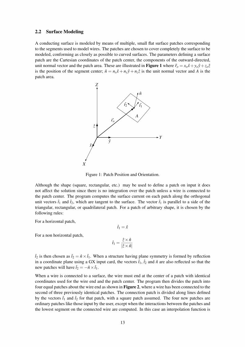
A conducting surface is modeled by means of multiple, small flat surface patches correspondingto the segments used to model wires. The patches are chosen to cover completely the surface to bemodeled, conforming as closely as possible to curved surfaces. The parameters defining a surfacepatch are the Cartesian coordinates of the patch center, the components of the outward-directed,unit normal vector and the patch area. These are illustrated in Figure 1 where~ro = xox+yoy+ zozis the position of the segment center; n = nxx+ nyy+ nzz is the unit normal vector and A is thepatch area.
X
Y
Z
~ro
xy
z
A
n
t1t2
Figure 1: Patch Position and Orientation.
Although the shape (square, rectangular, etc.) may be used to define a patch on input it doesnot affect the solution since there is no integration over the patch unless a wire is connected tothe patch center. The program computes the surface current on each patch along the orthogonalunit vectors t1 and t2, which are tangent to the surface. The vector t1 is parallel to a side of thetriangular, rectangular, or quadrilateral patch. For a patch of arbitrary shape, it is chosen by thefollowing rules:
For a horizontal patch,t1 = x
For a non horizontal patch,
t1 =z× n|z× n|
t2 is then chosen as t2 = n× t1. When a structure having plane symmetry is formed by reflectionin a coordinate plane using a GX input card, the vectors t1, t2 and n are also reflected so that thenew patches will have t2 =−n× t1.
When a wire is connected to a surface, the wire must end at the center of a patch with identicalcoordinates used for the wire end and the patch center. The program then divides the patch intofour equal patches about the wire end as shown in Figure 2, where a wire has been connected to thesecond of three previously identical patches. The connection patch is divided along lines definedby the vectors t1 and t2 for that patch, with a square patch assumed. The four new patches areordinary patches like those input by the user, except when the interactions between the patches andthe lowest segment on the connected wire are computed. In this case an interpolation function is
13

t1
t2
Figure 2: Connection of a Wire to a Surface Patch.
applied to the four patches to represent the current from the wire onto the surface, and the functionis numerically integrated over the patches. Thus, the shape of the patch is significant in this case.The user should try to choose patches so that those with wires connected are approximately squarewith sides parallel to t1 and t2. The connected wire is not required to be normal to the patch butcannot lie in the plane of the patch. Only a single wire may connect to a given patch and a wiresegment may have a patch connection on only one of its ends. Also, a wire may never connect toa patch formed by subdividing another patch for a previous connection.
As with wire modeling, patch size measured in wavelengths is very important for accuracy of theresults. A minimum of about 25 patches should be used per square wavelength of surface area,with the maximum size for an individual patch about 0.04 square wavelengths. Large patchesmay be used on large smooth surfaces while smaller patches are needed in areas of small radiusof curvature, both for geometrical modeling accuracy and for accuracy of the integral equationsolution. In the case of an edge, a precise local representation cannot be included; however, smallerpatches in the vicinity of the edge can lead to more accurate results since the current magnitudemay vary rapidly in this region. Since connection of a wire to a patch causes the patch to bedivided into four smaller patches, a larger patch may be input in anticipation of the subdivision.
While patch shape is not input to the program, very long narrow patches should be avoided whensubdividing the surface. This is illustrated by the two methods of modeling a sphere shown inFigure 3. The first uses uniform division in azimuth and equal cuts along the vertical axis. Thisresults in all patches having equal areas but with long narrow patches near the equator. In thesecond method, the number of divisions in azimuth is increased toward the equator so that thepatch length and width are kept more nearly equal. The areas are again kept approximately equal.
The results of the two segmentations are shown in Figure 4 and Figure 5 for scattering by asphere of ka (21 radius / wavelength) equal to 5.3. The uniform segmentation used 14 incrementsin azimuth and 14 equal bands along the vertical axis. The variable segmentation used 13 equalincrements in arc length along the vertical axis, with each band from top to bottom divided intothe following number of patches in azimuth : 4, 8, 12, 16, 20, 24, 24, 24, 20, 16, 12, 8, 4. Muchbetter agreement with experiment is obtained with the variable segmentation.
In general, the use of surface patches is restricted to modeling voluminous bodies. The surfacemodeled must be closed since the patches only model the side of the surface from which their
14

Figure 3: Patch Models for a Sphere.
Figure 4: Scattering from a Sphere with Uniform Segmentation.
Figure 5: Scattering from a Sphere with Variable Segmentation.
15

normals are directed outward. If a somewhat thin body, such as a box with one narrow dimension,is modeled with patches the narrow sites (edges) must be modeled as well as the broad surfaces.Furthermore, the parallel surface on opposite sides cannot be too close together or severe numericalerror will occur.
When modeling complex structures with features not previously encountered, accuracy may bechecked by comparison with reliable experimental data if available. Alternatively, it may be pos-sible to develop an idealized model for which the correct results can be estimated while retainingthe critical features of the desired model. The optimum model for a class of structures can beestimated by varying the segment and patch density and observing the effect on the results. Somedependence of results on segmentation will always be found. A large dependence, however, wouldindicate that the solution has not converged and more segments or patches should be used. A modelwill generally be usable over a band of frequencies. For frequencies beyond the upper limit of aparticular model, a new set of geometry cards must be input with a finer segmentation.
16
2.3 Modeling Structures Over Ground
Several options are available in NEC for modeling an antenna over a ground plane. For a perfectlyconducting ground, the code generates an image of the structure reflected in the ground surface.The image is exactly equivalent to a perfectly conducting ground and results in solution accuracycomparable to that for a free-space model. Structures may be close to the ground or contacting itin this case. However, for a horizontal wire with radius a, and height h to the wire axis,
√h2+a2
should be greater than about 10−6 wavelengths. Furthermore, the height should be at least severaltimes the radius for the thin-wire approximation to be valid. This method doubles the time to fillthe interaction matrix. A finitely conducting ground may be modeled by an image modified by theFresnel plane-wave reflection coefficients. This method is fast but of limited accuracy and shouldnot be used for structures close to the ground. The reflection coefficient approximation for the nearfields can yield reasonable accuracy if the structure is a least several tenths of a wavelength abovethe ground. It should not be used for structures having a large horizontal extent over the groundsuch as some traveling-wave antennas. An alternate method (Sommerfeld/Norton), available forwires only, uses the exact solution for the fields in the presence of ground and is accurate close tothe ground. For a horizontal wire the height restriction is the same as for a perfect ground. Whenthis method is used NEC requires an input file (TAPE21) containing field values for the specificground parameters and frequency. This interpolation table must be generated by running a separateprogram, SOMNEC, prior to the NEC run. The present NEC code uses the Sommerfeld / Nortonmethod only for wire-to-wire interactions. If Sommerfeld / Norton is requested for a structurethat includes surfaces, the reflection coefficient approximation will be used for surface-to-surfaceand surface-to-wire interactions. Computation of wire-to-wire interactions by the Sommerfeld /Norton method take about four times longer than for free space. In addition, computation of the in-terpolation table requires about 15sec on a CDC 7600 computer. However, the file of interpolationtables may be saved and reused for problems having the same ground parameters and frequency.
A wire ground screen may be modeled with the Sommerfeld / Norton method if it is raised slightlyabove the ground surface. A ground stake cannot be modeled in NEC since there is presently noprovision to compute interactions across the interface. Wires may end on a ground plane with acondition that the charge density (ie. derivative of current) be zero at the base of the wire, butthis is accurate only for a perfectly conducting ground. A wire may end on a finitely conductingground with the charge set to zero at the connection, but this will not accurately model a groundstake. If a wire is driven against a finitely conducting ground in this way, the input impedance willtypically be dependent on length of the source segment.
Also included are options for a radial-wire ground-screen approximation and two-medium groundapproximation (cliff) based on modified reflection coefficients. These methods are implementedonly for wires and not for patches, however. For the radial-wire ground-screen approximation,an approximate surface impedance - based on the wire density and the ground parameters - iscomputed at specular reflection points. Since the formula for surface impedance yields zero atthe center of the screen, the current on a vertical monopole will be the same as over a perfectground. The ground screen approximation is used in computing both near-field interactions andthe radiated field. It should be noted that diffraction from the edge of the screen is not included.When limited accuracy can be accepted, the ground screen approximation provides a large timesaving over explicit modeling with the Sommerfeld / Norton method since the ground screen doesnot increase the number of unknowns in the matrix equation.
The two-medium ground approximation permits the user to define a linear or circular cliff withdifferent ground parameters and ground height on opposite sides. This approximation is not usedfor the near-field interactions affecting the currents but is used in computing the radiated field. Thereflection coefficient is based on the ground parameters and height at the specular-reflection point
17

for each ray. This option may also be used to compute the current over a perfect ground and thencompute radiated fields for a finitely conducting ground.
18

3 Program Input
When NEC was first developed computer programs where loaded via a deck of punch cards.The NEC data cards where divided into blocks of columns each representing a field. A commonfeature of NEC data cards is that the first field (columns 1 and 2) contains a two-letter commandmneumonic. The following diagram illustrates the general card layout :
__________________________________________________________________________________________/2| 10| 20| 30| 40| 50| 60| 70| 80|
/ | | | | | | | | || | | | | | | | | || | | | | | | | | || | | | | | | | | || | | | | | | | | || | | | | | | | | || | | | | | | | | || The numbers along the top refer to the last column in each field. | | || | | | | | | | | |
This format has various drawbacks eg. it’s not very human readable and limits the precision ofnumeric fields. However, it’s a format which has been used for several decades so it’s essential thatit be supported. In future a new command format will also be implemented, probably a parameter/ value pair structure which will remove the limits of the original format.
3.1 Comment Cards
The data-card deck for a run must begin with one or more comment cards which can contain abrief description and structure parameters for the run. The cards are printed at the beginning ofthe output of the run for identification only and have no effect on the computation. Any alphabeticand numeric characters can be included in these cards. There are two forms for comment cardswhich are described below.
3.1.1 CM - Comment Card
Purpose : Create a comment string to be prepended to the program output.
Format : CM [Comment string]
Notes :
• When a CM card is read, the contents of columns 3 through 80 are printed in the output, andthe next card is read as a comment card.
3.1.2 CE - End Comment Card
Purpose : Create a final comment string to be prepended to the program output.
Format : CE [Comment string]
Notes :
• When a CE card is read, columns 3 through 80 are printed, and reading of comments isterminated.
• The card ammediately following a CE card must be a geometry card.
19

• A CE Card must always occur in a data deck and may be preceded by as many CM cards asare needed to describe the run.
20

3.2 Structure Geometry Cards
Structure geometry cards are used to define the physical structure of the object to be analysed. Thebasic building blocks are wire segments and patches.
Structure geometry cards are formated as shown in the following illustration :___________________________________________________________________________________________
/2| 5| 10| 20| 30| 40| 50| 60| 70| 80|/ | | | | | | | | | || | I1 | I2 | F1 | F2 | F3 | F4 | F5 | F6 | F7 || | | | | | | | | | || | | | | | | | | | || | | | | | | | | | || | | | | | | | | | || | | | | | | | | | || The numbers along the top refer to the last column in each field. | | || | | | | | | | | | |
Each card begins with a command mnemonic comprised of two characters (columns), this is fol-lowed by two integer fields (I1 and I2) each comprised of five characters (columns). The remainingcolumns are floating point fields (F1 to F7) each comprised of ten characters (columns). Numericfields which are not required for a particular command should be left blank.
3.2.1 GA - Wire Arc Specification
Purpose : Generate a circular arc of wire segments.
Format : GA ITG NS RADA ANG1 ANG2 RAD
Parameters :
• Integer Fields :
ITG (I1) - Tag number assigned to all segments of the wire arc.
NS (I2) - Number of segments into which the arc will be divided.
• Floating-Point Fields :
RADA (F1) - Arc radius (center is the origin and the axis is the y axis.
ANG1 (F2) - Angle of first end of the arc measured from the x-axis in a left-hand directionabout the y-axis (degrees).
ANG2 (F3) - Angle of the second end of the arc.
RAD (F4) - Wire radius.
Notes :
• The segments generated by GA form a section of polygon inscribed within the arc.
• If an arc in a different position or orientation is desired the segments may be moved with aGM card.
• Use of GA to form a circle will not result in symmetry being used in the calculation. It is agood way to form the beginning of the circle, to be completed by GR, however.
• See notes for GW.
21
3.2.2 GE - End Geometry Input
Purpose : Terminate reading geometry data cards and reset geometry data if a ground plane isused.
Format : GE FLAG
Parameters :
• Integer Fields :
FLAG (I1) - Geometry ground plain flag :
0 - No ground plane is present.1 - Indicates a ground plane is present. Structure symmetry is modified as required,
and the current expansion is modified so that the currents on segments touch-ing the ground (X, Y plane) are interpolated to their images below the ground(charge at base is zero).
-1 - Indicates a ground is present. Structure symmetry is modified as required. Cur-rent expansion, however, is not modified, Thus, currents on segments touchingthe ground will go to zero at the ground.
Notes :
• The basic function of the GE card is to terminate reading of geometry data cards. In doingthis, it causes the program to search through the segment data that have been generated bythe preceding cards to determine which wires are connected for current expansion.
• At the time that the GE card is read, the structure dimensions must be in units of meters.
• A positive or negative value of I1 does not cause a ground to be included in the calcula-tion. It only modifies the geometry data as required when a ground is present. The groundparameters must be specified on a program control card following the geometry cards.
• When I1 is nonzero, no segment my extend below the ground plane (X,Y plane) or lie inthis plane. Segments my end on the ground plane, however.
• If the height of a horizontal wire is less than 10-3 times the segment length, I1 equal to 1will connect the end of every segment in the wire to ground. I1 should be -1 to avoid thisdisaster.
• As an example of how the symmetry of a structure is affected by the presence of groundplane (X,Y plane), consider a structure generated with cylindrical symmetry about the Zaxis. The presence of a ground does not effect the cylindrical symmetry. If however thissame structure is rotated off the vertical, cylindrical symmetry is lost in the presence of theground. As a second example, consider a dipole parallel to the Z axis, which was generatedwith symmetry about its feed. The presence of a ground plane destroys this symmetry. Theprogram modifies structure symmetries as follows when I1 is nonzero. If the structure wasrotated about the X or Y axis by the GM card, all symmetry is lost (ie. the no-symmetrycondition is set). If the structure was not rotated about the X or Y axis, only symmetryabout a plane parallel to the X, Y plane is lost. Translation or a structure does not affectsymmetries.
22

3.2.3 GF - Read Numerical Green’s Function File
Purpose : Read a previously written Numerical Green’s Function (NGF) file.
Format : GF FLAG
Parameters :
• Integer Fields :
FLAG (I1) - Numerical Green’s Function flag :
6= 0 - Prints a table of the coordinates of the ends of all segments in the NumericalGreen’s Function.
= 0- Print normally.
Notes :
• GF must be the first card in the structure geometry section, immediately after CE. Theeffects of some other data cards are altered when a GF card is used.
• See Section III-5.
23

3.2.4 GH - Helix/Spiral Specification
Purpose : Generate a helix or spiral of wire segments
Format : GH ITG NS S HL A1 B1 A2 B2 RAD
Parameters :
• Integer Fields :
ITG (I1) - Tag number assigned to all segments of the helix or spiral.
NS (I2) - Number of segments into which the helix or spiral will be divided.
• Floating-Point Fields :
S (F1) - Spacing between turns.
HL (F2) - Total length of the helix.
A1 (F3) - Radius in x at z = 0.
B1 (F4) - Radius in y at z = 0.
A2 (F5) - Radius in x at z = HL.
B2 (F6) - Radius in y at z = HL.
RAD (F7) - Radius of wire.
Notes :
• Structure will be a helix if A2= A1 and HL> 0.
• Structure will be a spiral if A2= A1 and HL= 0.
• Unless it has been fixed in the codes in circulation, the use of HL = 0 for a flat spiral willresult in division by zero in NEC-2. GH was a non-official addition to NEC-2.
• HL negative gives a left-handed helix.
• HL positive gives a right-handed helix.
24
3.2.5 GM - Coordinate Transformation
Purpose : Translate or rotate a structure with respect to the coordinate system or to generate newstructures translated or rotated from the original. The translation is performed on thestructure defined in the preceding geometry card.
Format : GM ITGI NRPT ROX ROY ROZ XS XY XZ ITS
Parameters :
• Integer Fields :
ITGI (I1) - Tag number increment.
NRPT (I2) - The number of new structures to be generated
• Floating-Point Fields :
ROX (F1) - Angle in degrees through which the structure is rotated about the X-axis. Apositive angle causes a right-hand rotation.
ROY (F2) - Angle of rotation about Y-axis.
ROZ (F3) - Angle of rotation about Z-axis.
XS (F4) - X component of vector by which structure is translated with respect to thecoordinate system.
YS (F5) - Y component of translation vector.
ZS (F6) - Z component of translation vector.
ITS (F7) - This field is input as a decimal number but is rounded to an integer before use.Segment numbers are searched sequentially until one matching ITS is found.This segment and all segments through to the end of the sequence are movedby the card. If ITS is blank (usual case) or zero, the entire structure is moved.
Notes :
• If NRPT is zero, the structure is moved by the specified rotation and translation leaving noth-ing in the original location. If NRPT is greater than zero, the original structure remains fixedand NRPT new structures are formed, each shifted from the previous one by the requestedtransformation.
• The tag increment, ITGI, is used when new structures are generated (NRPT greater than zero)to avoid duplication of tag numbers. Tag numbers of the segments in each new copy of thestructure are incremented by ITGI from the tags on the previous copy or original. Tagsof segments which are generated from segments having no tags (tag equal to zero) are notincremented. Generally, ITGI will be greater than or equal to the largest tag number usedon the original structure to avoid duplication of tags. For example, if tag numbers 1 through100 have been used before a (GM) card is read having NRPT equal to 2, then ITGI equal to100 will cause the first copy of the structure to have tags from 101 to 200 and the secondcopy from 201 to 300. If NRPT is zero, the tags on the original structure will be incremented.
• The result of a transformation depends on the order in which the rotations and translationare applied. The order used is first rotation about X-axis, then rotation about the Y-axis, thenrotation about the Z-axis and, finally, translation by (XS, YS, ZS). All operations refer tothe fixed coordinate system axes. If a different order is desired, separate GM cards may beused.
25

3.2.6 GR - Generate Cylindrical Structure
Purpose : Reproduce a structure by rotating about the Z-axis to form a complete cylindrical array,and to set flags so that symmetry is utilized in the solution.
Format : GR ITGI I2
Parameters :
• Integer Fields :
ITGI (I1) - Tag number increment.
I2 (I2) - Total number of times that the structure is to occur in the cylindrical array.
Notes :
• The tag increment (ITGI) is used to avoid duplication of tag numbers in the reproducedstructures. In forming a new structure for the array, all valid tags on the previous copy ororiginal structure are incremented by (ITGI). Tags equal to zero are not incremented.
• The GR card should never be used when there are segments on the Z-axis or crossing theZ-axis since overlapping segments would result.
• The GR card sets flags so the program makes use of cylindrical symmetry in solving forthe currents. If a structure modeled by N segments has M sections in cylindrical symmetry(formed by a GR card with I2 equal to M), the number of complex numbers in matrixstorage and the proportionality factors for matrix fill time and matrix factor time are :
Matrix Fill FactorStorage Time Time——— ——– ———
No Symmetry N2 N2 N2
M Symmetric Sections N2/M N2/M N2/M
The matrix factor time represents the optimum for a large matrix factored in core. Generally,somewhat longer times will be observed.
• If the structure is added to or modified after the GR card in such a way that cylindricalsymmetry is destroyed, the program must be reset to a no-symmetry condition. In mostcases, the program is set by the geometry routines for the existing symmetry. Operationsthat automatically reset the symmetry conditions are :
– Addition of a wire by a GW card destroys all symmetry.– Generation of additional structures by a GM card, with NRPT greater than zero, de-
stroys all symmetry.– A GM card acting on only part of the structure (having ITS greater than zero) destroys
all symmetry.– A GX or GR card will destroy all previously established symmetry.– If a structure is rotated about either the X or Y axis by use of a GM card and a ground
plane is specified on the GE card, all symmetry will be destroyed. Rotation about theZ-axis or translation will not affect symmetry. If a ground is not specified, symmetrywill be unaffected by any rotation or translation by a GM card, unless NRPT or ITS onthe GM card is greater than zero.
• Symmetry will also be destroyed if lumped loads are placed on the structure in an unsym-metric manner. In this case, the program is not automatically set to a no-symmetry condition
26

but must be set by a data card following the GR card. A GW card with NS blank will setthe program to a no-symmetry condition without modifying the structure. The card mustspecify a nonzero radius, however, to avoid reading a GC card.
• Placement of nonradiating networks or sources does not affect symmetry.
• When symmetry is used in the solution, the number of symmetric sections (I2) is limitedby array dimensions. In the demonstration deck, the limit is 16 sections.
• The GR card produces the same effect on the structure as a GM card if I2 on the GR cardis equal to (NRPT+1) on the GM card and if ROZ on the GM card is equal to 360/(NRPT+1)degrees. If the GM card is used, however, the program will not be set to take advantage ofsymmetry.
27

3.2.7 GS - Scale Structure Dimensions
Purpose : Scale all dimensions of a structure by a constant.
Format : GS SCALE
Parameters :
• Floating-Point Fields :
SCALE (F1) - All structure dimensions, including wire radii, are multiplied by this value.
Notes :
• At the end of geometry input, structure dimensions must be in units of meters. Hence, if thedimensions have been input in other units, a GS card must be used to convert to meters.
28

3.2.8 GW - Wire Specification
Purpose : Generate a string of segments to represent a straight wire.
Format : GW ITG NS XW1 YW1 ZW1 XW2 YW2 ZW2 RADGC RDEL RAD1 RAD2
The first card defines a string of segments with radius RAD. If RAD is zero or blank, the secondcard is read to set parameters to taper the segment lengths and radius from one end of the wire tothe other.
Parameters :
• Integer Fields :
ITG (I1) - Tag number assigned to all segments of the wire.
NS (I2) - Number of segments into which the wire will be divided.
• Floating-Point Fields :
XW1 (F1) - X coordinate of wire end 1
YW1 (F2) - Y coordinate of wire end 1
ZW1 (F3) - Z coordinate of wire end 1
XW2 (F4) - X coordinate of wire end 2
YW2 (F5) - Y coordinate of wire end 2
ZW2 (F6) - Z coordinate of wire end 2
RAD (F7) - Wire radius, or zero for tapered segment option.
Optional GC card parameters :
RDEL (F1) - Ratio of the length of a segment to the length of the previous segment in thestring.
RAD1 (F2) - Radius of the first segment in the string.
RAD2 (F3) - Radius of the last segment in the string.
The ratio of the radii of adjacent segments is :
RRAD= (RAD2/RAD1)(1/(NS−1))
If the total wire length is L, the length of the first segment is :
S1 = L(1−RDEL)/(1−RDELNS)or
S1 = L/NS if RDEL= 1.
Notes :
• The tag number is for later use when a segment must be identified, such as when connectinga voltage source or lumped load to the segment. Any number except zero can be used as atag. When identifying a segment by its tag, the tag number and the number of the segmentin the set of segments having that tag are given. Thus, the tag of a segment does not need tobe unique. If no need is anticipated to refer back to any segments on a wire by tag, the tag
29

field may be left blank. This results in a tag of zero which cannot be referenced as a validtag.
• If two wires are electrically connected at their ends, the identical coordinates should beused for the connected ends to ensure that the wires are treated as connected for currentinterpolation. If wires intersect away from their ends, the point of intersection must occur atsegment ends within each wire for interpolation to occur. Generally, wires should intersectonly at their ends unless the location of segment ends is accurately known.
• The only significance of differentiating end one from end two of a wire is that the positivereference direction for current will be in the direction from end one to end two on eachsegment making up the wire.
• As a rule of thumb, segment lengths should be less than 0.1 wave- length at the desiredfrequency. Somewhat longer segments may be used on long wires with no abrupt changes,while shorter segments, 0.05 wavelength or less, may be required in modeling critical re-gions of an antenna.
• If input is in units other than meters, then the units must be scaled to meters through the useof a Scale Structure Dimensions (GS) card.
30
3.2.9 GX - Reflection in Coordinate Planes
Purpose : Form structures having planes of symmetry by reflecting part of the structure in thecoordinate planes, and to set flags so that symmetry is utilized in the solution.
Format : GX ITGI XYZ
Parameters :
• Integer Fields :
ITGI (I1) - Tag number increment.
XYZ (I2) - This integer is divided into three independent digits, in columns 8, 9 and10 of the card, which control reflection in the three orthogonal coordinateplanes. A one in column 8 causes reflection along the X-axis (reflection inY, Z plane); a one in column 9 causes reflection along the Y-axis; and a onein column 10 causes reflection along the Z axis. A zero or blank in any ofthese columns causes the corresponding reflection to be skipped.
Notes :
• Any combination of reflections along the X, Y and Z axes may be used. For example, 101for (I2) will cause reflection along axes X and Z, and 111 will cause reflection along axes X,Y and Z. When combinations of reflections are requested, the reflections are done in reversealphabetical order. That is, if a structure is generated in a single octant of space and a GXcard is then read with I2 equal to 111, the structure is first reflected along the Z-axis; thestructure and its image are then reflected along the Y-axis; and, finally, these four structuresare reflected along the X-axis to fill all octants. This order determines the position of asegment in the sequence and, hence, the absolute segment numbers.
• The tag increment I1 is used to avoid duplication of tag numbers in the image segments. Allvalid tags on the original structure are incremented by I1 on the image. When combinationsof reflections are employed, the tag increment is doubled after each reflection. Thus, a tagincrement greater than or equal to the largest tag an the original structure will ensure thatno duplicate tags are generated. For example, if tags from 1 to 100 are used on the originalstructure with I2 equal to 011 and a tag increment of 100, the first reflection, along the Z-axis, will produce tags from 101 to 200; and the second reflection, along the Y-axis, willproduce tags from 201 to 400, as a result of the increment being doubled to 200.
• The GX card should never be used when there are segments located in the plane about whichreflection would take place or crossing this plane. The image segments would then coincidewith or intersect the original segments, and such overlapping segments are not allowed.Segments may end on the image plane, however.
• When a structure having plane symmetry is formed by a GX card, the program will makeuse of the symmetry to simplify solution for the currents. The number of complex numbersin matrix storage and the proportionality factors for matrix fill time and matrix factor timefor a structure modeled by N segments are :
31

No. of Planes Matrix Fill Factorof Symmetry Storage Time Time
0 N2 N2 N31 N2/2 N2/2 N3/42 N2/4 N2/4 N3/163 N2/8 N2/8 N3/64
The matrix factor time represents the optimum for a large matrix factored in core. Generally,somewhat longer times will be observed.
• If the structure is added to or modified after the GX card in such a way that symmetry is de-stroyed, the program must be reset to a no-symmetry condition. In most cases, the programis set by the geometry routines for the existing symmetry. Operations that automaticallyreset the symmetry condition are :
– Addition of a wire by a GW card destroys all symmetry.
– Generation of additional structures by a GM card, with NRPT greater than zero, de-stroys all symmetry.
– A GM card acting on only part of the structure (having ITS greater than zero) destroysall symmetry.
– A GX card or GR card will destroy all previously established symmetry. For exam-ple, two GR cards with I2 equal to 011 and 100, respectively, will produce the samestructure as a single GX card with I2 equal to 111; however, the first case will set theprogram to use symmetry about the Y, Z plane only while the second case will makeuse of symmetry about all three coordinate planes.
– If a ground plane is specified on the GE card, symmetry about a plane parallel to theX, Y plane will be destroyed. Symmetry about other planes will be used, however.
– If a structure is rotated about either the X or Y axis by use of a GM card and a groundplane is specified on the GE card, all symmetry will be destroyed. Rotation about theZ-axis or translation will not affect symmetry. If a ground is not specified, no rotationor translation will affect symmetry conditions unless NRPT on the GM card is greaterthan zero.
– Symmetry will also be destroyed if lumped loads are placed on the structure in an un-symmetric manner. In this case, the program is not automatically set to a no-symmetrycondition but must be set by a data card following the GX card. A GW card with NSblank will set the program to a no-symmetry condition without modifying the struc-ture. The card must specify a nonzero radius, however, to avoid reading a GC card.
• Placement of sources or nonradiating networks does not affect symmetry.
32

3.2.10 SP - Surface Patch
Purpose : To input parameters of a single surface patch.
Format : SP NS X1 Y1 Z1 X2 Y2 Z2If NS is 1, 2, or 3, a second card is read in the following format :SC NS X3 Y3 Z3 X4 Y4 Z4
Parameters :
• Integer Fields :
NS (I1) - Selects patch shape :
0 - Arbitrary patch shape (default).1 - Rectangular patch.2 - Triangular patch.3 - Quadrilateral patch.
• Floating-Point Fields :
Arbitrary shape (NS = 0) :
X1 (F1) - X coordinate of patch center.
Y1 (F2) - Y coordinate of patch center.
Z1 (F3) - Z coordinate of patch center.
X2 (F4) - Elevation angle above the X-Y plane of outward normal vector (degrees).
Y2 (F5) - Azimuth angle from X-axis of outward normal vector (degrees).
Z2 (F6) - Patch area (square of units used).
Rectangular, triangular, or quadrilateral patch (NS = 1, 2, or 3) :
X1 (F1) - X coordinate of corner 1.
Y1 (F2) - Y coordinate of corner 1.
Z1 (F3) - Z coordinate of corner 1.
X2 (F4) - X coordinate of corner 2.
Y2 (F5) - Y coordinate of corner 2.
Z2 (F6) - Z coordinate of corner 2.
X3 (F1) - X coordinate of corner 3.
Y3 (F2) - Y coordinate of corner 3.
Z3 (F3) - Z coordinate of corner 3.
For the quadrilateral patch only (NS = 3) :
X4 (F4) - X coordinate of corner 4.
Y4 (F5) - Y coordinate of corner 4.
Z4 (F6) - Z coordinate of corner 4.
Notes :
33
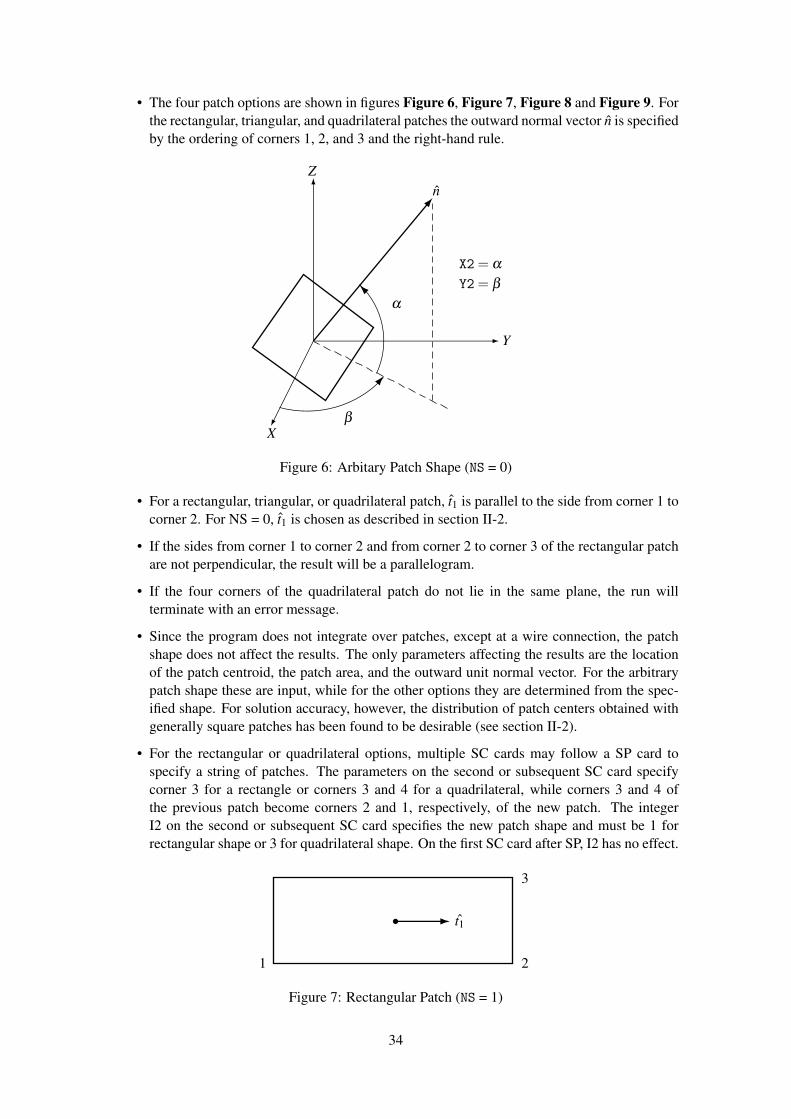
• The four patch options are shown in figures Figure 6, Figure 7, Figure 8 and Figure 9. Forthe rectangular, triangular, and quadrilateral patches the outward normal vector n is specifiedby the ordering of corners 1, 2, and 3 and the right-hand rule.
n
X
Y
Z
α
β
X2= α
Y2= β
Figure 6: Arbitary Patch Shape (NS = 0)
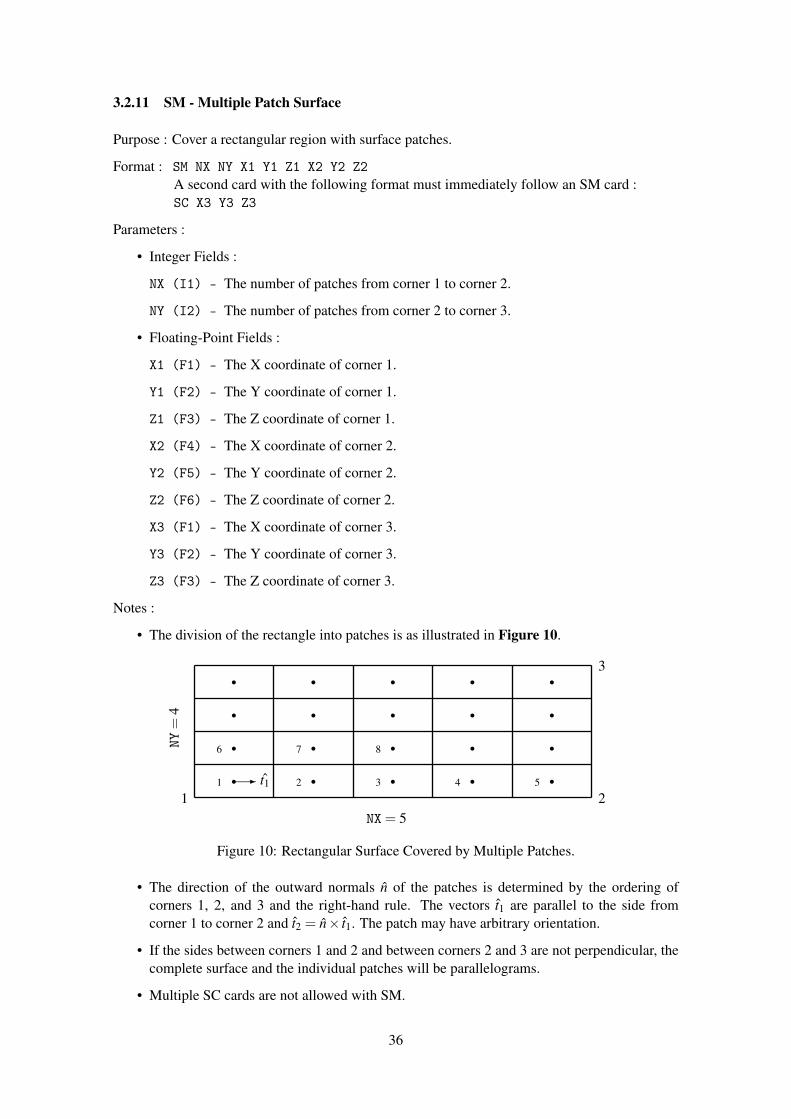
• For a rectangular, triangular, or quadrilateral patch, t1 is parallel to the side from corner 1 tocorner 2. For NS = 0, t1 is chosen as described in section II-2.
• If the sides from corner 1 to corner 2 and from corner 2 to corner 3 of the rectangular patchare not perpendicular, the result will be a parallelogram.
• If the four corners of the quadrilateral patch do not lie in the same plane, the run willterminate with an error message.
• Since the program does not integrate over patches, except at a wire connection, the patchshape does not affect the results. The only parameters affecting the results are the locationof the patch centroid, the patch area, and the outward unit normal vector. For the arbitrarypatch shape these are input, while for the other options they are determined from the spec-ified shape. For solution accuracy, however, the distribution of patch centers obtained withgenerally square patches has been found to be desirable (see section II-2).
• For the rectangular or quadrilateral options, multiple SC cards may follow a SP card tospecify a string of patches. The parameters on the second or subsequent SC card specifycorner 3 for a rectangle or corners 3 and 4 for a quadrilateral, while corners 3 and 4 ofthe previous patch become corners 2 and 1, respectively, of the new patch. The integerI2 on the second or subsequent SC card specifies the new patch shape and must be 1 forrectangular shape or 3 for quadrilateral shape. On the first SC card after SP, I2 has no effect.
t1
1 2
3
Figure 7: Rectangular Patch (NS = 1)
34

t1
1 2
3
Figure 8: Triangular Patch (NS = 2).
t1
12
3
4
Figure 9: Quadrilateral Patch (NS = 3).
Rectangular or quadrilateral patches may be intermixed, but triangular or arbitrary shapesare not allowed in a string of linked patches.
35
3.2.11 SM - Multiple Patch Surface
Purpose : Cover a rectangular region with surface patches.
Format : SM NX NY X1 Y1 Z1 X2 Y2 Z2A second card with the following format must immediately follow an SM card :SC X3 Y3 Z3
Parameters :
• Integer Fields :
NX (I1) - The number of patches from corner 1 to corner 2.
NY (I2) - The number of patches from corner 2 to corner 3.
• Floating-Point Fields :
X1 (F1) - The X coordinate of corner 1.
Y1 (F2) - The Y coordinate of corner 1.
Z1 (F3) - The Z coordinate of corner 1.
X2 (F4) - The X coordinate of corner 2.
Y2 (F5) - The Y coordinate of corner 2.
Z2 (F6) - The Z coordinate of corner 2.
X3 (F1) - The X coordinate of corner 3.
Y3 (F2) - The Y coordinate of corner 3.
Z3 (F3) - The Z coordinate of corner 3.
Notes :
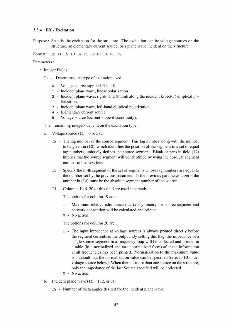
• The division of the rectangle into patches is as illustrated in Figure 10.
1 2 3 4 5
6 7 8
t11 2
3
NX= 5
NY=
4
Figure 10: Rectangular Surface Covered by Multiple Patches.
• The direction of the outward normals n of the patches is determined by the ordering ofcorners 1, 2, and 3 and the right-hand rule. The vectors t1 are parallel to the side fromcorner 1 to corner 2 and t2 = n× t1. The patch may have arbitrary orientation.
• If the sides between corners 1 and 2 and between corners 2 and 3 are not perpendicular, thecomplete surface and the individual patches will be parallelograms.
• Multiple SC cards are not allowed with SM.
36

3.3 Program Control Cards
The program control cards follow the structure geometry cards. They set electrical parameters forthe model, select options for the solution procedure and request data computation. The cards arelisted below by their mnemonic identifier with a brief description of their function :
Group I EK - Extended thin-wire kernel flagFR - Frequency specificationGN - Ground parameter specificationKH - Interaction approximation rangeLD - Structure impedance loading
Group II EX - Structure excitation cardNT - Two-port network specificationTL - Transmission line specification
Group III CP - Coupling calculationEN - End of data flagGD - Additional ground parameter specificationsNE - Near electric field requestNH - Near magnetic field requestNX - Next structure flagPL - Data Storage for PlottingPQ - Wire charge density print controlPT - Wire-current print controlRP - Radiation pattern requestWG - Write Numerical Green’s Function fileXQ - Execute card
There is no fixed order for the program control cards. However a logical arrangement would beto start with the desired parameters and options to set, followed by requests for calculation ofcurrents, near fields and radiated fields. Parameters that are not set in the input data are givendefault values. The one exception to this is the excitation (EX) which must be set.
Computation of currents may be requested using an XQ card. RP, NE, or NH cards cause calcu-lation of the currents and radiated or near fields on the first occurrence. Subsequent RP, NE, orNH cards cause computation of fields using the previously calculated currents. Any number ofnear-field and radiation-pattern requests may be grouped together in a data deck. An exception tothis occurs when multiple frequencies are requested by a single FR card. In this case, only a singleNE or NH card and a single RP card will remain in effect for all frequencies.
All parameters retain their values until changed by subsequent data cards. Hence, after parame-ters have been set and currents or fields computed, selected parameters may be changed and thecalculations repeated. For example, if a number of different excitations are required at a single fre-quency, the deck could have the form FR, EX, XQ, EX, XQ, etc. If a single excitation is requiredat a number of frequencies, the cards EX, FR, XQ, FR, XQ, etc. could be used.
When the antenna is modified and additional calculations are requested, the order of the cards may,in some cases, affect the solution time since the program will repeat only that part of the solutionaffected by the changed parameters. For this reason, the user should understand the relation of thedata cards to the solution procedure. The first step in the solution is to calculate the interactionmatrix, which determines the response of the antenna to an arbitrary excitation, and to factor thismatrix in preparation for solution of the matrix equation. This is the most time-consuming singlestep in the solution procedure. The second step is to solve the matrix equation for the currents
37

due to a specific excitation. Finally, the near fields or radiated fields may be computed from thecurrents.
The interaction matrix depends only on the structure geometry and the cards in Group I of theprogram control cards. Thus, computation and factorization of the matrix is not repeated if cardsbeyond Group I are changed. On the other hand, antenna currents depend on both the interactionmatrix and the cards in Group II, so that the currents must be recomputed whenever cards inGroup I or II are changed. The near fields depend only on the structure currents while the radiatedfields depend on the currents and on the GD card, which contains special ground parameters forthe radiated-field calculation. An example of the implications of these rules is presented by thefollowing two sets of data cards :
FR, EX, NT1, LD1, XQ, LD2, XQ, NT2, LD1, XQ, LD2, XQ
FR, EX, LD1, NT1, XQ, NT2, XQ, LD2, NT1, XQ, NT2, XQ
Calculation and factoring of the matrix would be required four times by the first set but only twiceby the second set while obtaining the same information.
The program control cards are explained on the following pages. The format of all programcontrol cards has four integers and six floating point numbers. The integers are contained incolumns 3 through 5, 6 through 10, 11 through 15, and 16 through 20 (each integer field stops atan integral multiple of 5 columns), and the floating point numbers are contained in fields of 10 forthe remainder of the card (ie. from 21 through 30, 31 through 40, etc.). Integers are right justifiedin their fields. The floating point numbers can be punched either as a string of digits containing adecimal point, punched anywhere in the field; or as a string of digits containing a decimal pointand followed by an exponent of ten in the form E+I or E-I which multiplies the number by 10+I
or 10−I respectively. The integer exponent must be right-justified in the field.
Program control cards are formated as shown in the following illustration :____________________________________________________________________________________________
/2| 5| 10| 15| 20| 30| 40| 50| 60| 70| 80|/ | | | | | | | | | | || | I1 | I2 | I3 | I4 | F1 | F2 | F3 | F4 | F5 | F6 || | | | | | | | | | | || | | | | | | | | | | || | | | | | | | | | | || | | | | | | | | | | || | | | | | | | | | | || The numbers along the top refer to the last column in each field. | | || | | | | | | | | | | |
Each card begins with a command mnemonic comprised of two characters (columns), this is fol-lowed by four integer fields (I1 to I4) each comprised of five characters (columns). The remainingcolumns are floating point fields (F1 to F6) each comprised of ten characters (columns). Numericfields which are not required for a particular command should be left blank.
38

3.3.1 CP - Maximum Coupling Calculation
Purpose : Request calculation of the maximum coupling between segments.
Format : CP TAG1 SEG1 TAG2 SEG2
Parameters :
• Integer Fields :
TAG1 (I1) - Specify segment number SEG1 in the set of segments having tag TAG1.
SEG1 (I2) - If TAG1 is blank or zero, then SEG1 is the segment number.
TAG2 (I3) - Specify segment number SEG2 in the set of segments having tag TAG2.
SEG2 (I4) - If TAG2 is blank or zero, then SEG2 is the segment number.
Notes :
• Up to five segments may be specified on 2-1/2 CP cards. Coupling is computed between allpairs of these segments. When more than two segments are specified, the CP cards must begrouped together. A new group of CP cards replaces the old group.
• CP does not cause the program to proceed with the calculation but only sets the segmentnumbers. The specified segments must then be excited (EX card) one at a time in the speci-fied order and the currents computed (XQ, RP, NE, or NH card). The excitation must use theapplied-field voltage-source model. When all of the specified segments have been excited inthe proper order, the couplings will be computed and printed. After the coupling calculationthe set of CP cards is canceled.
39

3.3.2 EK - Extended Thin-Wire Kernel
Purpose : Control use of the extended thin-wire kernel approximation.
Format : EK ITMP1
Parameters:
• Integer Fields :
ITMP1 (I1) - Control use of the thin-wire kernel :
0 - Initiate use of the extended thin-wire kernel.-1 - Use the standard thin-wire kernel (default).
Note :
• Without an EK card, the program will use the standard thin-wire kernel.• If the EK card is included with no argument then use the extended thin-wire kernel.
40

3.3.3 EN - End of Run
Purpose : Indicate to the program the end of all execution.
Format : EN
Parameters : None
41
3.3.4 EX - Excitation
Purpose : Specify the excitation for the structure. The excitation can be voltage sources on thestructure, an elementary current source, or a plane wave incident on the structure.
Format : EX I1 I2 I3 I4 F1 F2 F3 F4 F5 F6
Parameters :
• Integer Fields :
I1 - Determines the type of excitation used :
0 - Voltage source (applied-E-field).1 - Incident plane wave, linear polarization.2 - Incident plane wave, right-hand (thumb along the incident k-vector) elliptical po-
larization.3 - Incident plane wave, left-hand elliptical polarization.4 - Elementary current source.5 - Voltage source (current-slope-discontinuity).
The remaining integers depend on the excitation type :
a. Voltage source (I1 = 0 or 5) :
I2 - The tag number of the source segment. This tag number along with the numberto be given in (I3), which identifies the position of the segment in a set of equaltag numbers, uniquely defines the source segment. Blank or zero in field (I2)implies that the source segment will be identified by using the absolute segmentnumber in the next field.
I3 - Specify the m-th segment of the set of segments whose tag numbers are equal tothe number set by the previous parameter. If the previous parameter is zero, thenumber in (I3) must be the absolute segment number of the source.
I4 - Columns 19 & 20 of this field are used separately.
The options for column 19 are :
1 - Maximum relative admittance matrix asymmetry for source segment andnetwork connection will be calculated and printed.
0 - No action.
The options for column 20 are :
1 - The input impedance at voltage sources is always printed directly beforethe segment currents in the output. By setting this flag, the impedance of asingle source segment in a frequency loop will be collected and printed ina table (in a normalized and an unnormalized form) after the informationat all frequencies has been printed. Normalization to the maximum valueis a default, but the normalization value can be specified (refer to F3 undervoltage source below). When there is more than one source on the structure,only the impedance of the last Source specified will be collected.
0 - No action.
b. Incident plane wave (I1 = 1, 2, or 3) :
I2 - Number of theta angles desired for the incident plane wave.
42

I3 - Number of phi angles desired for the incident plane wave.
I4 - Only column 19 is used. The options are :
1 - Maximum relative admittance matrix asymmetry for network connectionswill be calculated and printed.
0 - No action.
c. Elementary current source (I1 = 4) :
I2 - Blank.
I3 - Blank.
I4 - Only column 19 is used and its function is identical to that listed under b.
• Floating-Point Fields :
The floats depend on the excitation type :
a. Voltage source (I1 = 0 or 5) :
F1 - Real part of the voltage in volts.
F2 - Imaginary part of the voltage in volts.
F3 - If a one is placed in column 20 (see above), this field can be used to specify anormalization constants for the impedance printed in the optional impedance table.Blank in this field produces normalization to the maximum value.
F4 - Blank.
F5 - Blank.
F6 - Blank.
b. Incident plane wave (I1 = 1, 2, or 3) :
The incident wave is characterized by the direction of its k vector, and by an angle ofpolarization in the plane normal to k.
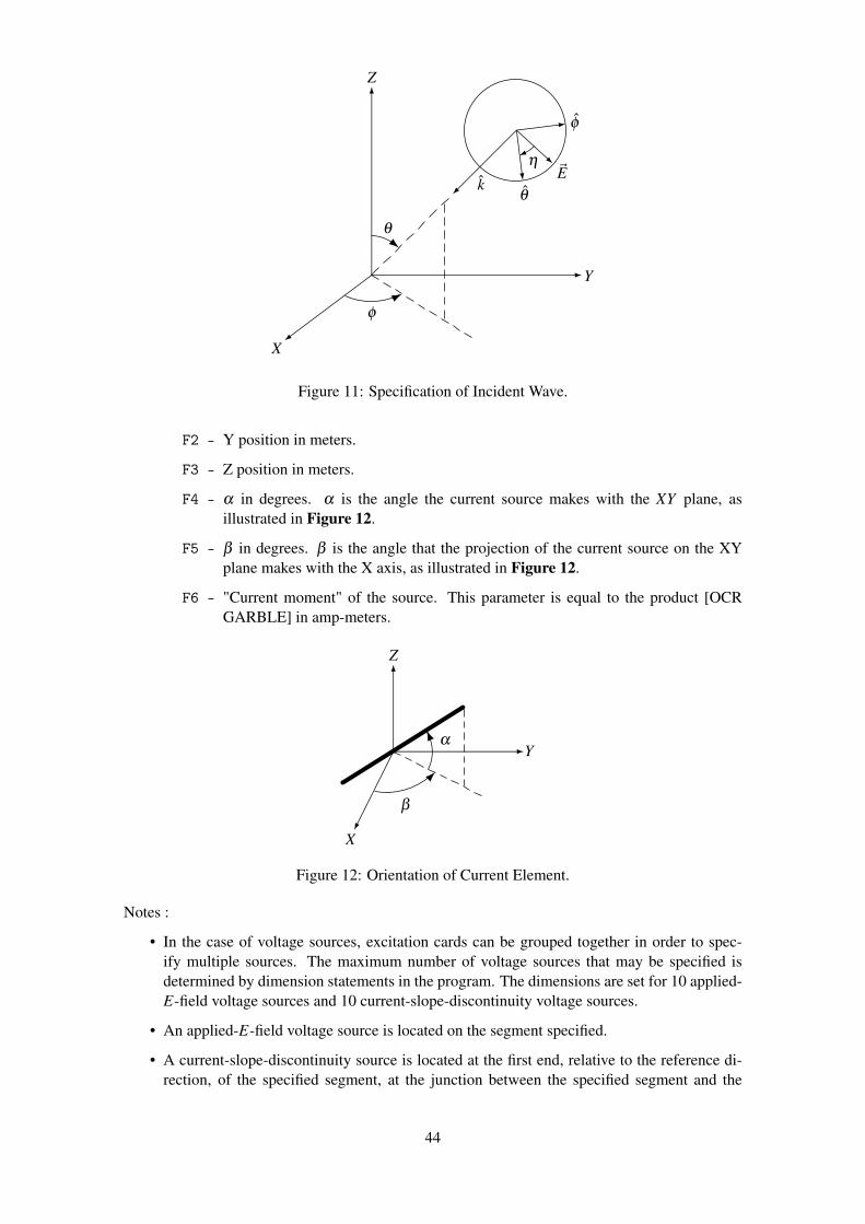
F1 - θ in degrees. θ is a standard spherical coordinate, measured from the Z-axis asillustrated in Figure 11.
F2 - φ in degrees. φ is the standard spherical angle defined in the XY plane, measuredaround the Z-axis.
F3 - η in degrees. η is a polarization angle, defined as the angle between the θ -directedunit vector and the electric-field (E) vector for linear polarization, or the majorellipse axis for elliptical polarization. Refer to Figure 11.
F4 - θ angle stepping increment in degrees.
F5 - φ angle stepping increment in degrees.
F6 - Ratio of minor axis to major axis for elliptical polarization.
c. Elementary current source (I1 = 4) :
The current source is characterized by its Cartesian coordinate position, orientation andits magnitude.
F1 - X position in meters.
43
X
Y
Z
~Eθ
φ
k
θ
φ
η
Figure 11: Specification of Incident Wave.
F2 - Y position in meters.
F3 - Z position in meters.
F4 - α in degrees. α is the angle the current source makes with the XY plane, asillustrated in Figure 12.
F5 - β in degrees. β is the angle that the projection of the current source on the XYplane makes with the X axis, as illustrated in Figure 12.
F6 - "Current moment" of the source. This parameter is equal to the product [OCRGARBLE] in amp-meters.
X
Y
Z
α
β
Figure 12: Orientation of Current Element.
Notes :
• In the case of voltage sources, excitation cards can be grouped together in order to spec-ify multiple sources. The maximum number of voltage sources that may be specified isdetermined by dimension statements in the program. The dimensions are set for 10 applied-E-field voltage sources and 10 current-slope-discontinuity voltage sources.
• An applied-E-field voltage source is located on the segment specified.
• A current-slope-discontinuity source is located at the first end, relative to the reference di-rection, of the specified segment, at the junction between the specified segment and the
44

previous segment. This junction must be a simple two-segment junction. and the two seg-ments must be parallel with equal lengths and radii.
• A current-slope-discontinuity voltage source may lie in a symmetry plane. An applied fieldvoltage source may not lie in a symmetry plane since a segment may not lie in a symmetryplane. An applied-field voltage source may be used on a wire crossing a symmetry plane byexciting the two segments on opposite sides of the symmetry plane each with half the totalvoltage, taking account of the reference directions of the two segments.
• An applied-field voltage source specified on a segment which has been impedance-loaded,through the use of an LD card, is connected in series with the loads. An applied-field voltagesource specified on the same segment as a network is connected in parallel with the networkport. For the specific case of a transmission line, the source is in parallel with both the lineand the shunt load. Applied-field voltage sources should be used in these cases since loadsand network connections are located on, rather than between, segments.
• Only one incident plane-wave or one elementary current source is allowed at a time. Also,plane-wave or current-source excitation is not allowed with voltage sources. If the excitationtypes are mixed, the program will use the last excitation type encountered.
• When a number of θ and φ angles are specified for an incident plane-wave excitation, the θ
angle changes more rapidly than φ .
• The current element source illuminates the structure with the field of an infinitesimal currentelement at the specified location. The current element source cannot be used over a groundplane.
45

3.3.5 FR - Frequency
Purpose : Specify the frequency (frequencies) in MHz.
Format : FR IFRQ NFRQ FMHZ DELFRQ
Parameters :
• Integer Fields :
IFRQ (I1) - Determines the type of frequency stepping :
0 - Linear stepping.1 - Multiplicative stepping.
NFRQ (I2) - Number of frequency steps. If this field is blank, one is assumed.
• Floating-Point Fields :
FMHZ (F1) - Frequency in MHz.
DELFRQ (F2) - Frequency stepping increment. If the frequency stepping is linear, thisquantity is added to the frequency each time. If the stepping is multiplica-tive, this is the multiplication factor.
Notes :
• If a frequency card does not appear in the data deck, a single frequency of 299.8 MHz isassumed. Since the wavelength at 299.8 MHz is one meter, the geometry is in units ofwavelengths for this case.
• Frequency cards may not be grouped together. If they are, only the information on the lastcard in the group will be used.
• After an FR card with NFRQ greater than 1, an NE or SH card will not initiate execution,while an RP or XQ card will. In this case, only one NE or WH card and one RP card willbe effective for the multiple frequencies.
• After a frequency loop for NFRQ > 1 has been completed, it will not be repeated for a secondexecution request. The FR card must be repeated in this case.
46

3.3.6 GD - Additional Ground Parameters
Purpose : Specify the ground parameters of a second medium which is not in the immediate vicin-ity of the antenna. This card may only be used if a GN card has also been used. It doesnot affect the fields of surface patches.
Format : GD EPSR2 SIG2 CLT CHT
Parameters :
• Floating-Point Fields :
EPSR2 (F1) - Relative dielectric constant of the second medium.
SIG2 (F2) - Conductivity in mhos/meter of the second medium.
CLT (F3) - Distance in meters from the origin of the coordinate system to the joinbetween medium 1 and 2. This distance is either the radius of the circlewhere the two media join or the distance out the +X axis to where the twomedia join in a line parallel to the Y axis. Specification of the circular orlinear option is on the RP card. See Figure 13.
CHT (F4) - Distance in meters (positive or zero) by which the surface of medium 2 isbelow medium 1.
Origin
Medium 1
Medium 2
CLT
CHT
Figure 13: Parameters for a Second Ground Medium.
Notes :
• The GD card can only be used in a data set where the GN card has been used, since the GNcard is the only way to specify the ground parameters in the vicinity of the antenna (see GNcard write-up). However, a number of GD cards may be used in the same data set with onlyone GN card.
• GD cards may not be grouped together. If they are, only the information on the last card ofthe group is retained.
• When a second medium is specified, a flag must also be set on the radiation pattern (RP)data card in order to calculate the patterns including the effect of the second medium. Referto the radiation- pattern card write-up for details.
• Use of the GD card does not require recalculation of the matrix or currents.
• The parameters for the second medium are used only in the calculation of the far fields. Itis possible then to set the radius of the boundary between the two media equal to zero andthus have the far fields calculated by using only the parameters of medium 2. The currentsfor this case will still have been calculated by using the parameters of medium 1.
47

• When a model includes surface patches, the fields due to the patches will be calculated byusing only the primary ground parameters. Hence, a second ground medium should not beused with patches.
48
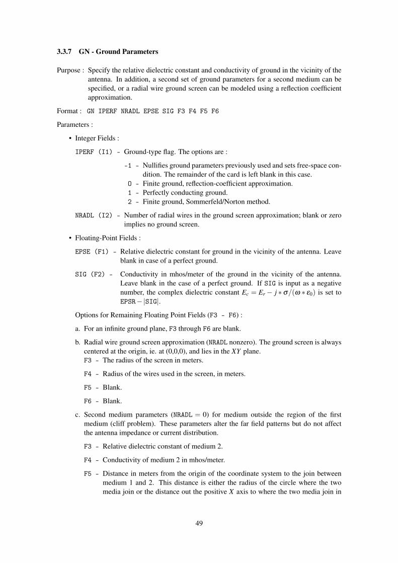
3.3.7 GN - Ground Parameters
Purpose : Specify the relative dielectric constant and conductivity of ground in the vicinity of theantenna. In addition, a second set of ground parameters for a second medium can bespecified, or a radial wire ground screen can be modeled using a reflection coefficientapproximation.
Format : GN IPERF NRADL EPSE SIG F3 F4 F5 F6
Parameters :
• Integer Fields :
IPERF (I1) - Ground-type flag. The options are :
-1 - Nullifies ground parameters previously used and sets free-space con-dition. The remainder of the card is left blank in this case.
O - Finite ground, reflection-coefficient approximation.1 - Perfectly conducting ground.2 - Finite ground, Sommerfeld/Norton method.
NRADL (I2) - Number of radial wires in the ground screen approximation; blank or zeroimplies no ground screen.
• Floating-Point Fields :
EPSE (F1) - Relative dielectric constant for ground in the vicinity of the antenna. Leaveblank in case of a perfect ground.
SIG (F2) - Conductivity in mhos/meter of the ground in the vicinity of the antenna.Leave blank in the case of a perfect ground. If SIG is input as a negativenumber, the complex dielectric constant Ec = Er− j ∗σ/(ω ∗ ε0) is set toEPSR−|SIG|.
Options for Remaining Floating Point Fields (F3 - F6) :
a. For an infinite ground plane, F3 through F6 are blank.
b. Radial wire ground screen approximation (NRADL nonzero). The ground screen is alwayscentered at the origin, ie. at (0,0,0), and lies in the XY plane.F3 - The radius of the screen in meters.
F4 - Radius of the wires used in the screen, in meters.
F5 - Blank.
F6 - Blank.
c. Second medium parameters (NRADL = 0) for medium outside the region of the firstmedium (cliff problem). These parameters alter the far field patterns but do not affectthe antenna impedance or current distribution.
F3 - Relative dielectric constant of medium 2.
F4 - Conductivity of medium 2 in mhos/meter.
F5 - Distance in meters from the origin of the coordinate system to the join betweenmedium 1 and 2. This distance is either the radius of the circle where the twomedia join or the distance out the positive X axis to where the two media join in
49

a line parallel to the Y axis. Specification of the circular or linear option is on theRP card. See Figure 13.
F6 - Distance in meters (positive or zero) by which the surface of medium 2 is belowmedium 1.
Notes :
• When the Sommerfeld/Norton method is used, NEC requires an input-data file (TAPE21)that is generated by the program SOMNEC for the specific ground parameters and frequency(see section III-4). The file generated by SOMNEC depends only on the complex dielectricconstant, Ec = Er− j ∗σ/(ω ∗ ε0). NEC compares Ec from the file with that determinedby the GN card parameters and frequency. If the relative difference exceeds 10−3, an errormessage is printed. Once TAPE21 has been read for the first use of the Sommerfeld/Nortonmethod, the data is retained until the end of the run. Subsequent data, including new datasets following XQ[?] cards, may use the TAPE21 data if the ground parameters and fre-quency (thus, Ec) remain unchanged. Other ground options may be intermixed with theSommerfeld/Norton option.
• The parameters of the second medium can also be specified on another data card whosemnemonic is GD. With the GD card, the parameters of the second medium can be variedand only the radiated fields need to be recalculated. Furthermore, if a radial wire groundscreen has been specified on the GN card, the GD card is the only way to include a secondmedium. See the write-up of the GD card for details.
• GN cards may not be grouped together. If they are, only the information on the last cardwill be retained.
• Use of a GN card after any form of execute dictates structure matrix regeneration.
• Only the parameters of the first medium are used when the antenna currents are calculated; the parameters associated with the second medium are not used until the calculation ofthe far fields. It is possible then to calculate the currents over one set of ground parameters(medium one), but to calculate the far fields over another set (medium two) by setting thedistance to the start of medium two to zero. Medium one can even be a perfectly conductingground specified by IPERF= 1.
• When a radial wire ground screen or a second medium is specified, it is necessary to indicatetheir presence by the first parameter on the RP card in order to generate the proper radiationpatterns.
• When a ground plane is specified, this fact should also be indicated on the GE card. Referto the GE card for details.
• When a model includes surface patches, the fields due to the patches will be calculated byusing only the primary ground parameters. Hence, a second ground medium should not beused with patches. The radial wire ground screen approximation also is not implementedfor patches.
50

3.3.8 KH - Interaction Approximation Range
Purpose : Set the minimum separation distance for use of a time-saving approximation in fillingthe interaction matrix.
Format : KH RKH
Parameters:
• Floating-Point Fields :
RKH (F1) - The approximation is used for interactions over distances greater than RKHwavelengths.
Notes :
• If two segments or a segment and a patch are separated by more than RKH wavelengths, theinteraction field is computed from an impulse approximation to the segment current. Thefield of a current element located at the segment center is used. No approximation is usedfor the field due to the surface current on a patch since the time for the standard calculationis very short.
• The KH card can be placed anywhere in the data cards following the geometry cards (withFR, EX, LD, etc.) and affects all calculations requested following its occurrence. The valueof RKH may be changed within a data set by use of a new KH card.
51
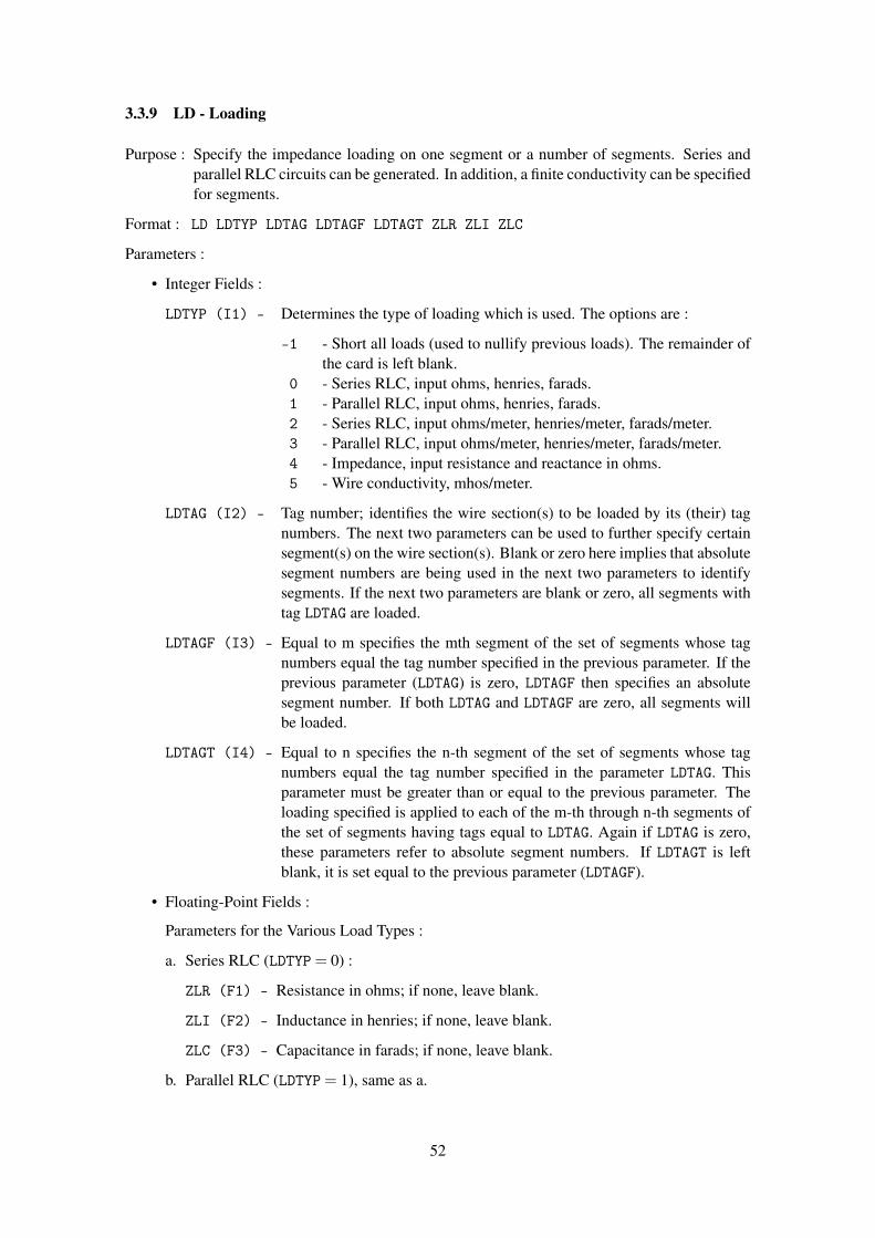
3.3.9 LD - Loading
Purpose : Specify the impedance loading on one segment or a number of segments. Series andparallel RLC circuits can be generated. In addition, a finite conductivity can be specifiedfor segments.
Format : LD LDTYP LDTAG LDTAGF LDTAGT ZLR ZLI ZLC
Parameters :
• Integer Fields :
LDTYP (I1) - Determines the type of loading which is used. The options are :
-1 - Short all loads (used to nullify previous loads). The remainder ofthe card is left blank.
0 - Series RLC, input ohms, henries, farads.1 - Parallel RLC, input ohms, henries, farads.2 - Series RLC, input ohms/meter, henries/meter, farads/meter.3 - Parallel RLC, input ohms/meter, henries/meter, farads/meter.4 - Impedance, input resistance and reactance in ohms.5 - Wire conductivity, mhos/meter.
LDTAG (I2) - Tag number; identifies the wire section(s) to be loaded by its (their) tagnumbers. The next two parameters can be used to further specify certainsegment(s) on the wire section(s). Blank or zero here implies that absolutesegment numbers are being used in the next two parameters to identifysegments. If the next two parameters are blank or zero, all segments withtag LDTAG are loaded.
LDTAGF (I3) - Equal to m specifies the mth segment of the set of segments whose tagnumbers equal the tag number specified in the previous parameter. If theprevious parameter (LDTAG) is zero, LDTAGF then specifies an absolutesegment number. If both LDTAG and LDTAGF are zero, all segments willbe loaded.
LDTAGT (I4) - Equal to n specifies the n-th segment of the set of segments whose tagnumbers equal the tag number specified in the parameter LDTAG. Thisparameter must be greater than or equal to the previous parameter. Theloading specified is applied to each of the m-th through n-th segments ofthe set of segments having tags equal to LDTAG. Again if LDTAG is zero,these parameters refer to absolute segment numbers. If LDTAGT is leftblank, it is set equal to the previous parameter (LDTAGF).
• Floating-Point Fields :
Parameters for the Various Load Types :
a. Series RLC (LDTYP= 0) :
ZLR (F1) - Resistance in ohms; if none, leave blank.
ZLI (F2) - Inductance in henries; if none, leave blank.
ZLC (F3) - Capacitance in farads; if none, leave blank.
b. Parallel RLC (LDTYP= 1), same as a.
52

c. Series RLC (LDTYP= 2) input parameters per unit length :
ZLR (F1) - Resistance in ohms/meter; if none, leave blank.
ZLI (F2) - Inductance in henries/meter; if none, leave blank.
ZLC (F3) - Capacitance in farads/meter; if none, leave blank.
d. Parallel RLC (LDTYP= 3), input parameters per unit length otherwise same as c.
e. Impedance (LDTYP= 4) :
ZLR (F1) - Resistance in ohms.
ZLI (F2) - Reactance in ohms.
f. Wire conductivity (LDTYP= 5) :
ZLR (F1) - Conductivity in mhos/meter.
Notes :
• Loading cards can be input in groups to achieve a desired structure loading. The maximumnumber of loading cards in a group is determined by dimensions in the program. The limitis presently 30.
• If a segment is loaded more than once by a group of loading cards, the loads are assumed tobe in series (impedances added), and a comment is printed in the output alerting the user tothis fact.
• When resistance and reactance are input (LDTYP = 4), the impedance does not automati-cally scale with frequency.
• Loading cards used after any form of execute, require regeneration of the structure matrix.
• Since loading modifies the interaction matrix, it will affect the conditions of plane or cylin-drical symmetry of a structure. If a structure is geometrically symmetric and each sym-metric section is to receive identical loading, then symmetry may be used in the solution.The program is set to utilize symmetry during geometry input by inputting the data for onesymmetric section and completing the structure with a GR or GX card. If symmetry is used,the loading on only the first symmetric section is input on LD cards. The same loading willbe assumed on the other sections. Loading should not be specified for segments beyond thefirst section when symmetry is used. If the sections are not identically loaded, then duringgeometry input the program must be set to a no-symmetry condition to permit independentloading of corresponding segments in different sections.
53

3.3.10 NE - Near Field (Electric)
Purpose : Request calculation of near electric fields in the vicinity of the antenna.
Format : NE NEAR NRX NRY NRZ XNR YNR ZNR DXNR DYNR DZNR
Parameters :
• Integer Fields :
NEAR (I1) - Coordinate system type :
0 - Rectangular coordinates.1 - Spherical coordinates.
a. Rectangular coordinates (NEAR= 0) :
NRX (I2) - The number of points desired in the x, y, and z directions respectively.
NRY (I3) - The value for x changes most rapidly, then y, and then z.
NRZ (I4) - A value of 1 is assumed for any field left blank.
b. Spherical coordinates (NEAR= 1) :
NRX (I2) - The number of points desired in the r, φ , and θ directions, respectively.
NRY (I3) - The value for r changes most rapidly, then φ , and then θ .
NRZ (I4) - A value of 1 is assumed for any field left blank.
• Floating-Point Fields :
The specification of floating-point fields depends on the coordinate system chosen.
a. Rectangular coordinates (NEAR= 0) :
XNR (F1) - The x, y and z coordinate positions respectively,
YNR (F2) - of the first field point
ZNR (F3) - (in meters).
DXNR (F4) - Coordinate stepping increment, in meters, for the x, y and z
DYNR (F5) - coordinates, respectively. In stepping, x changes most rapidly,
DZNR (F6) - then y, and then z.
b. Spherical coordinates (NEAR= 1) :
XNR (F1) - The r, φ and θ ) coordinate positions respectively,
YNR (F2) - of the first field point. r is in meters, and
ZNR (F3) - φ and θ are in degrees.
DXNR (F4) - Coordinate stepping increments for r, φ , and θ ,
DYNR (F5) - respectively. The stepping increment for r is in meters,
DZNR (F6) - and for φ and θ is in degrees.
Notes :
54

• When only one frequency is being used, near-field cards may be grouped together in orderto calculate fields at points with various coordinate increments. For this case, each cardencountered produces an immediate execution of the near-field routine and the results areprinted. When automatic frequency stepping is being used (ie. when the number of fre-quency steps (NFRQ) on the FR card is greater than one), only one NE or NH card can beused for program control inside the frequency loop. Furthermore, the NE or NH card doesnot cause an execution in this case. Execution will begin only after a subsequent radiation-pattern card (RP) or execution card (XQ) is encountered (see respective write-ups on bothof these cards).
• The time required to calculate the field at one point is equivalent to filling one row of thematrix. Thus, if there are N segments in the structure, the time required to calculate fields atN points is equivalent to the time required to fill an N x N interaction matrix.
• The near electric field is computed by whichever form of the field equations was selected forfilling the matrix, either the thin-wire approximation or extended thin-wire approximation.At large distances from the structure, the segment currents are treated as infinitesimal currentelements.
• If the field calculation point falls within a wire segment, the point is displaced by the radiusof that segment in a direction normal to the plane containing each source segment and thevector from that source segment to the observation segment. When the specified field-calculation point is at the center of a segment, this convention is the same as is used infilling the interaction matrix. If the field point is on a segment axis, that segment producesno contribution to the H-field or the radial component of the E-field. If these componentsare of interest, the field point should be on or outside of the segment surface.
55

3.3.11 NH - Near Field (Magnetic)
Purpose : Request calculation of near magnetic fields in the vicinity of the antenna.
Format : NH NEAR NRX NRY NRZ XNR YNR ZNR DXNR DYNR DZNR
Notes :
• Refer to sub-section NE - Near Field (Electric).
56
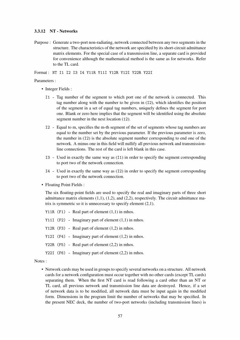
3.3.12 NT - Networks
Purpose : Generate a two-port non-radiating, network connected between any two segments in thestructure. The characteristics of the network are specified by its short-circuit admittancematrix elements. For the special case of a transmission line, a separate card is providedfor convenience although the mathematical method is the same as for networks. Referto the TL card.
Format : NT I1 I2 I3 I4 Y11R Y11I Y12R Y12I Y22R Y22I
Parameters :
• Integer Fields :
I1 - Tag number of the segment to which port one of the network is connected. Thistag number along with the number to be given in (I2), which identifies the positionof the segment in a set of equal tag numbers, uniquely defines the segment for portone. Blank or zero here implies that the segment will be identified using the absolutesegment number in the next location (12).
I2 - Equal to m, specifies the m-th segment of the set of segments whose tag numbers areequal to the number set by the previous parameter. If the previous parameter is zero,the number in (I2) is the absolute segment number corresponding to end one of thenetwork. A minus one in this field will nullify all previous network and transmission-line connections. The rest of the card is left blank in this case.
I3 - Used in exactly the same way as (I1) in order to specify the segment correspondingto port two of the network connection.
I4 - Used in exactly the same way as (I2) in order to specify the segment correspondingto port two of the network connection.
• Floating Point Fields :
The six floating-point fields are used to specify the real and imaginary parts of three shortadmittance matrix elements (1,1), (1,2), and (2,2), respectively. The circuit admittance ma-trix is symmetric so it is unnecessary to specify element (2,1).
Y11R (F1) - Real part of element (1,1) in mhos.
Y11I (F2) - Imaginary part of element (1,1) in mhos.
Y12R (F3) - Real part of element (1,2) in mhos.
Y12I (F4) - Imaginary part of element (1,2) in mhos.
Y22R (F5) - Real part of element (2,2) in mhos.
Y22I (F6) - Imaginary part of element (2,2) in mhos.
Notes :
• Network cards may be used in groups to specify several networks on a structure. All networkcards for a network configuration must occur together with no other cards (except TL cards)separating them. When the first NT card is read following a card other than an NT orTL card, all previous network and transmission line data are destroyed. Hence, if a setof network data is to be modified, all network data must be input again in the modifiedform. Dimensions in the program limit the number of networks that may be specified. Inthe present NEC deck, the number of two-port networks (including transmission lines) is
57

limited to thirty, and the number of different segments having network ports connected tothem is limited to thirty.
• One or more network ports can be connected to any given segment. Multiple network portsconnected to one segment are connected in parallel.
• If a network is connected to a segment which has been impedance loaded (ie. through theuse of the LD card), the load acts in series with the network port.
• A voltage source specified on the same segment as a network port is connected in parallelwith the network port.
• Segments can be impedance-loaded by using network cards. Consider a network connectedfrom the segment to be loaded to some other arbitrary segment as shown in Figure 14. The
Z1 ShortPort 1 Port 2
Figure 14: Segment Loaded by Means of a 2-Port Network.
admittance matrix elements are Y11 = 1/Z1, Y12 = 0, and Y22 = infinity (computationally,a very large number such as 1010). The advantage of using this technique for loading isthat the load can be changed without causing a recalculation of the structure matrix as isrequired when LD cards are used. Furthermore, in some cases a higher degree of structurematrix symmetry can be preserved because the matrix elements are not directly modified bynetworks as they are when using the LD cards. (Consider for instance a loop with one loadwhere the loop is rotationally symmetric until the load is placed on it.) The disadvantageof the NT card form of loading is that the user must calculate the load admittance, andthis value does not automatically scale with frequency. Obviously, in the above schematic,replacing the short with an impedance would load two segments. At a segment at which avoltage source is specified, the effect of loading by the LD and NT cards differs, however,since the network is in parallel with the voltage source while the load specified by an LDcard is in series with the source.
• Use of network cards (NT) after any form of execute requires recalculation of the currentonly.
• NT and TL cards do not affect structure symmetry.
58

3.3.13 NX - Next Structure
Purpose : Signal the end of data for one structure and the beginning of data for the next.
Format : NX
Parameters : None
Notes :
• The card that directly follows the NX card must be a comment card CM.
59

3.3.14 PL - Data Storage for Plotting
Purpose : Set flags for writing selected output data into a predesignated file for later plotting.
Format : PL IPLP1 IPLP2 IPLP3 IPLP4
Parameters :
• Integer Fields :
IPLP1 (I1) - Data type to be written into the auxilliary file. Available options are :
0 - No action1 - Currents2 - Near fields3 - Patterns4 - Impedance, SWR5 - Admittance, SWR
The remaining integers depend on data type (as defined by the value of IPLP1) :
a. Currents (IPLP1 = 1) :
IPLP2 (I2) - Wire current component format. Available options are :
0 - No action1 - Real and imaginary2 - Magnitude and phase
IPLP3 (I3) - Surface patch current components. Available options are :
0 - No action1 - Ix2 - Iy3 - Iz4 - Ix, Iy, Iz (all measured in magnitude and phase)
b. Near Fields (IPLP1 = 2) :
IPLP2 (I2) - Near field components format. Available options are :
0 - No action1 - Real and imaginary2 - Magnitude and phase
IPLP3 (I3) - Near field components. Available options are :
0 - No action1 - X component2 - Y component3 - Z component4 - X, Y, Z component5 - Total Field (magnitude only)
IPLP4 (I4) - Coordinate to be stored. Available options are :
1 - X coordinate2 - Y coordinate3 - Z coordinate
60

c. Far field patterns (IPLP1 = 3) :
IPLP2 (I2) - Angles to be written into auxilliary file. Available options are :
1 - Theta (or Z for RP1)2 - Phi3 - Rho (for RP1)
IPLP3 (I3) - Electric field component. Available options are :
0 - No action1 - Etheta2 - Ephi (field components in magnitude and phase)3 - Erho (for RP1)
IPLP4 (I4) - Power pattern component. Available options are :
0 - No action1 - Vertical gain (dB)2 - Horizontal gain (dB)3 - Total gain (dB)4 - Vertical, Horizontal & Total Gain (dB)
Notes :
• The PL card may be used anywhere between the GE and XQ commands.
• A PL card with IPLP = 0 will suspend any previous PL specs.
• All the data requested is written out to the a file named F0R008.DAT.
61
3.3.15 PQ - Print Control For Charge on Wires
Purpose : Control printing of charge on wires.
Format : PQ IPTFLQ IPTAQ IPTAQF IPTAQT
Parameters :
• Integer Fields :
IPTFLQ (I1) - Print control flag :
-1 - Suppress printing of charge densities. This is the default condition.0 - (or blank) print charge densities on segments specified by the fol-
lowing parameters. If the following parameters are blank, chargedensities are printed for all segments.
IPTAQ (I2) - Tag number of the segments for which charge densities will be printed.
IPTAQF (I3) - Equal to m specifies the m-th segment of the set of segments having tagnumbers of IPTAQ. If IPTAQ is zero or blank, then IPTAQF refers to anabsolute segment number. If IPTAQF is left blank, then charge density isprinted for all segments.
IPTAQT (I4) - Equal to n, specifies the n-th segment of the set of segments having tagnumbers of IPTAQ. Charge densities are printed for segments having tagnumber IPTAQ starting at the mth segment in the set and ending at then-th segment. If IPTAQ is zero or blank, then IPTAQF and IPTAQT refer toabsolute segment numbers. If IPTAQT refer to absolute segment numbers.If IPTAQT is left blank, it is set equal to IPTAQF.
62

3.3.16 PT - Page Title / Print Control for Current on Wires
Purpose : Control the printing of currents on wire segments. Current printing can be suppressed,limited to a few segments, or special formats for receiving patterns can be requested.
Format : PT IPTFLG IPTAG IPTAGF IPTAGT
Parameters :
• Integer Fields :
IPTFLG (I1) - Print control flag, specifies the type of format used in printing segmentcurrents. The options are :
-2 - All currents printed. This it a default value for the program if thecard is omitted.
-1 - Suppress printing of all wire segment currents.0 - Current printing will be limited to the segments specified by the
next three parameters.1 - Currents are printed by using a format designed for a receiving pat-
tern (refer to output section in this manual). Only currents for thesegments specified by thenext three parameters are printed.
2 - Same as for 1 above; in addition, however, the current and the nor-malized values along with the for one segment will be normalizedto its maximum, relative strength in dB will be printed in a table. Ifthe currents for more than one segment are being printed, only cur-rents from the last segment in the group appear in the normalizedtable.
3 - Only normalized currents from one segment are printed for the re-ceiving pattern case.
IPTAG (I2) - Tag number of the segments for which currents will be printed.
IPTAGF (I3) - Equal to m, specifies the mth segment of the set of segments having the tagnumbers of IPTAG, at which printing of currents starts. If IPTAG is zeroor blank, then IPTAGF refers to an absolute segment number. If IPTAGFis blank, the current is printed for all segments.
IPTAGT (I4) - Equal to n specifies the n-th segment of the set of segments having tagnumbers of IPTAG. Currents are printed for segments having tag numberIPTAG starting at the m-th segment in the set and ending at the n-th seg-ment. If IPTAG is zero or blank, then IPTAGF and IPTAGT refer to absolutesegment numbers. In IPTAGT is left blank, it is set to IPTAGF.
63
3.3.17 RP - Radiation Pattern
Purpose : To specify radiation pattern sampling parameters and to cause program execution. Op-tions for a field computation include a radial wire ground screen, a cliff, or surface-wavefields.
Format : RP I1 NTH NPH XNDA THETS PHIS DTH RFLD GNOR
Parameters :
• Integer Fields :
I1 - Select the mode of calculation for the radiated field. Some values of I1will affect the meaning of the remaining parameters on the card. Optionsavailable are :
O - Normal mode. Space-wave fields are computed. An infinite groundplane is included if it has been specified previously on a GN card; oth-erwise, the antenna is in free space.
1 - Surface wave propagating along ground is added to the normal spacewave. This option changes the meaning of some of the other parameterson the RP card as explained below, and the results appear in a specialoutput format. Ground parameters must have been input on a GN card.The following options cause calculation of only the space wave but withspecial ground conditions. Ground conditions include a two-mediumground (cliff where the media join in a circle or a line), and a radialwire ground screen. Ground parameters and dimensions must be inputon a GN or GD card before the RP card is read. The RP card onlyselects the option for inclusion in the field calculation. (Refer to theGN and GD cards for further explanation.)
2 - Linear cliff with antenna above upper level. Lower medium parametersare as specified for the second medium on the GN card or on the GDcard.
3 - Circular cliff centered at the origin of the coordinate system with theantenna above the upper level. The lower medium parameters are asspecified for the second medium on the GN card or on the GD card.
4 - Radial wire ground screen centered at origin.5 - Both radial wire ground screen and linear cliff.6 - Both radial wire ground screen ant circular cliff.
The field point is specified in spherical coordinates (r, θ , φ ) as illustratedin Figure 15, except when the surface wave is computed. For computingthe surface wave field (I1= 1), cylindrical coordinates (ρ , φ , z) are used toaccurately define points near the ground plane at large radial distances. TheRP card allows automatic stepping of the field point to compute the fieldover a region about the antenna at uniformly spaced points. The integersNTH and NPH and floating point fields THETS, PHIS, DTH and DPH control thefield-point stepping.
NTH (I2) - The number of values of θ at which the field is to be computed (or numberof values of z, for I1= 1).
NPH (I3) - The number of values of φ at which the field is to be computed. The totalnumber of field points requested by the card is NTH×NPH. If NTH or NPH is
64

(R, θ , φ )
X
Y
Z
Rθ
φ
Spherical Coordinates
(ρ , φ , z)
X
Y
Z
z
ρ
φ
Cylindrical Coordinates
Figure 15: Coordinates for Radiated Field.
left blank, a value of one will be assumed.
XNDA (I4) - This optional integer consists of four independent digits in columns 17, 18,19 and 20, each having a different function. The mnemonic XNDA is not avariable name in the program. Rather, each letter represents a mnemonicfor the corresponding digit in XNDA. If 11 = 1, then XNDA has no effect andshould be left blank. The possible values for each digit are :
X - (column 17) controls output format, possible values are :
0 - Major-axis, minor-axis, and total gain printed.1 - Vertical, horizontal and total gain printed.
N - (column 18) causes normalized gain for the specified field points to beprinted after the standard gain output. The number of field points forwhich the normalized gain can be printed is limited by an array dimen-sion in the program. In the demonstration program, the limit is 600points. If the number of field points exceeds this limit, the remainingpoints will be omitted from the normalized gain. The gain may be nor-malized to its maximum or to a value input in field GNOR. The type ofgain that is normalized is determined by the value of N as follows :
0 - No normalized gain.1 - Major axis gain normalized.2 - Minor axis gain normalized.3 - Vertical axis gain normalized.4 - Horizontal axis gain normalized.5 - Total gain normalized.
D - (column 19) selects either power gain or directive gain for both standardprinting and normalization. If the structure excitation is an incidentplane wave, the quantities printed under the heading gainwill actuallybe the scattering cross section (a/λ 2) and will not be affected by thevalue of D. The column heading for the output will still read "power" or"directive gain," however.
0 - Power gain.1 - Directive gain.
65
A - (column 20) requests calculation of average power gain over the regioncovered by field points :
0 - No averaging.1 - Average gain computed.2 - Average gain computed; printing of gain at the field points used
for averaging is suppressed. If NTH or NPH is equal to one, averagegain will not be computed for any value of A since the area of theregion covered by field points vanishes.
• Floating Point Fields :
THETS (F1) - Initial θ angle in degrees (initial z coordinate in meters if I1= 1).
PHIS (F2) - Initial φ angle in degrees.
DTH (F3) - Increment for θ in degrees (increment for z in meters if I1= 1).
DPH (F4) - Increment for φ in degrees.
RFLD (F5) - Radial distance (R) of the field point from the origin in meters. RFLDis optional. If it is blank, the radiated electric field will have the factorexp(− jkR)/R omitted. If a value of R is specified, it should represent apoint in the far-field region since near components of the field cannot beobtained with an RP card. (If I1= 1, then RFLD represents the cylindricalcoordinate φ in meters and is not optional. It must be greater than aboutone wavelength.)
GNOR (F6) - Determines the gain normalization factor if normalization has been re-quested in the XNDA field. If GNOR is blank or zero, the gain will be normal-ized to its maximum value. If GNOR is not zero, the gain will be normalizedto the value of GNOR.
Notes :
• The RP card will initiate program execution, causing the interaction matrix to be computedand factored and the structure currents to be computed if these operations have not alreadybeen performed. Hence, all required input parameters must be set before the RP card is read.
• At a single frequency, any number of RP cards may occur in sequence so that different field-point spacings may be used over different regions of space. If automatic frequency steppingis being used (ie. NFRQ on the FR card is greater than one), only one RP card will act as datainside the loop. Subsequent cards will calculate patterns at the final frequency.
• When both NTH and NPH are greater than one, the angle θ (or z) will be stepped faster thanφ .
• When a ground plane has been specified, field points should not be requested below theground (θ greater than 90 degrees or z less than zero.)
66
3.3.18 TL - Transmission Line
Purpose : To generate a transmission line between any two points on the structure. Characteristicimpedance, length, and shunt admittance are the defining parameters.
Format : TL I1 I2 I3 I4 F1 F2 F3 F4 F5 F6
Parameters :
• Integer Fields :
The fields I1, I2, I3 and I4 are identical to those on the network (NT) card.
I1 - Tag number of the segment to which port one of the network is connected. Thistag number along with the number to be given in (I2), which identifies the positionof the segment in a set of equal tag numbers, uniquely defines the segment for portone. Blank or zero here implies that the segment will be identified using the absolutesegment number in the next location (12).
I2 - Equal to m, specifies the m-th segment of the set of segments whose tag numbers areequal to the number set by the previous parameter. If the previous parameter is zero,the number in (I2) is the absolute segment number corresponding to end one of thenetwork. A minus one in this field will nullify all previous network and transmission-line connections. The rest of the card is left blank in this case.
I3 - Used in exactly the same way as (I1) in order to specify the segment correspondingto port two of the network connection.
I4 - Used in exactly the same way as (I2) in order to specify the segment correspondingto port two of the network connection.
• Floating Point Fields :
F1 - The characteristic impedance of the transmission line in ohms. A negative sign infront of the characteristic impedance will act as a flag for generating the transmissionline with a 180 degree phase reversal (crossed line) if this is desired.
F2 - The length of transmission line in meters. If this field is left blank, the program willuse the straight line distance between the specified connection points.
The remaining four floating-point fields are used to specify the real and imaginary parts ofthe shunt admittances at end one and two, respectively.
F3 - Real part of the shunt admittance in mhos at end one.
F4 - Imaginary part of the shunt admittance in mhos at end one.
F5 - Real part of the shunt admittance in mhos at end two
F6 - Imaginary part of the shunt admittance in mhos at end two.
Notes :
• Fields I1, I2, I3 and I4 are identical to those on the network (NT) card.
• The rules for transmission-line cards are the same as for network cards. All transmission linecards for a particular transmission line configuration must occur together with no other cards(except NT cards) separating them. When the first TL or NT card is read following a cardother than a TL or NT card, all previous network or transmission line data are destroyed.Hence, if a set of TL cards is to be modified, all transmission-line and network data must
67

be input again in the modified form. Dimensions in the program limit the number of cardsin a group that may be specified. In the NEC demonstration deck, the number of two-port networks (specified by NT cards and TL cards) is limited to thirty, and the number ofdifferent segments having network ports connected to them is limited to thirty.
• One or more networks (including transmission lines) may be connected to any given seg-ment. Multiple network ports connected to one segment are connected in parallel.
• If a transmission line is connected to a segment that has been impedance loaded (ie. throughthe use of an LD card), the load acts in series with the line.
• Use of a transmission-line (TL) card after any form of execute requires recalculation of thecurrent only, and does not require recalculation of the matrix.
• NT and TL cards do not affect symmetry.
68

3.3.19 WG - Write NGF File
Purpose : Write a NGF (Numerical Green’s Function) file for a structure on the file TAPE20.
Format : WG
Parameters : None
Notes :
• See Section III-5.
69

3.3.20 XQ - Execute
Purpose : Initiate program execution at points in the data stream where execution is not automatic.Options on the card also allow for automatic generation of radiation patterns in eitherof two vertical cuts.
Format : XQ I1
Parameters :
• Integer Fields :
I1 - Options controlled by this field are :
0 - No patterns requested (normal case).1 - Generates a pattern cut in the XZ plane, ie. φ = 0 degrees and θ varies from 0
degrees to 90 degrees in 1 degree steps.2 - Generates a pattern cut in the YZ plane, ie. φ = 90 degrees and θ varies from 0
degrees to 90 degrees in 1 degree steps.3 - Generates both of the cuts described for the values 1 and 2.
Notes :
• For the case of a single frequency step, four cards will automatically produce program exe-cution (i.e., the program stops reading data and proceeds with the calculations requested tothat point); the four cards are the execute card (XQ), the near-field cards (NE, NH), and theradiation-pattern card (RP). Thus, the only time the XQ card is mandatory, for the case ofone frequency, is when only currents and impedances for the structure are desired. On theother hand, for the case of automatic frequency stepping, only the XQ card and the RP cardcause execution. Thus, if only near-fields or currents are desired, the XQ card is mandatoryto cause execution. Furthermore, the XQ card can always be used as a divider in the dataafter a card which produces an execute. For instance, if the user wished to put a blank XQcard after an RP card to more easily divide the data into execution groups, the XQ card willact as a do-nothing card.
• The radiation-pattern generation option of the XQ card must not be used when a radial wireground screen or a second medium has been specified. For these cases, the RP card is usedwhere the presence of the additional ground parameters is indicated.
70

3.4 SOMNEC Input For Sommerfeld / Norton Ground Method
When the Sommerfeld / Norton ground option is requested on the GN card, NEC reads interpola-tion tables from the file TAPE21. This file must be created prior to the NEC run by running theseparate program SOMNEC. SOMNEC reads a single data card with the parameters :
EPR, SIG, FMHZ, IPT (format 3E10.3, I5)
The three decimal numbers end in columns 10, 20, and 30 and the integer IPT must end in column35. The parameters are :
EPR - Relative dielectric constant of ground (Er)
SIG - Conductivity of ground in mhos/m (S)
FMHZ - Frequency in MHz
IPT - Output control :
1 - Print the interpolation table.0 - No printed output.
The interpolation tables depend only on the complex dielectric constant :
Ec = Er− j ∗SIG/(ω ∗ ε0) Er = EPR
If SIG is input as a negative number, the program sets :
Ec = EPR− j|SIG|,
and frequency is not used. The tables are written on the file TAPE21.
71
3.5 The Numerical Green’s Function Option
With the Numerical Green’s Function (NGF) option, a fixed structure and its environment may bemodeled and the factored interaction matrix saved on a file. New parts may then be added to themodel in subsequent computer runs and the complete solution obtained without repeating calcula-tion for the data on the file. The main purpose of the NGF is to avoid the unnecessary repetitionof calculations when a part of a model, such as a single antenna in a complex environment, willbe modified one or more times while the environment remains fixed. For example, when mod-eling antennas on ships, several antenna designs or locations may be considered on an otherwiseunchanged ship. With the NGF, the self-interaction matrix for the fixed environment may be com-puted, factored for solution, and saved on a tape or disk file. Solution for a new antenna thenrequires only the evaluation of the self-interaction matrix for the antenna, the mutual antenna-to-environment interactions, and matrix manipulations for a partitioned-matrix solution. When thepreviously written NGF file is used, the free-space Green’s function in the NEC formulation is, ineffect, replaced by the Green’s function for the environment.
Another reason for using the NGF option is to exploit partial symmetry in a structure. In a singlerun, a structure must be perfectly symmetric for NEC to use symmetry in the solution. Anyunsymmetric segments or patches, or ones that lie in a symmetry plane or on the axis of rotation,will destroy the symmetry. Such partial symmetry may be exploited to reduce solution time byrunning the symmetric part of the model first and writing a NGF file. The unsymmetric parts maythen be added in a second run.
Use of the NGF option may also be warranted for large, time-consuming models to save an ex-pensive result for further use. Without adding new antennas, it may be used with a new excitationor to compute new radiation, near-field, or coupling data not computed in the original run.
To write a NGF file for the structure, the data deck is constructed as for a normal run. After the GEcard, the frequency, ground parameters, and loading may be set by FR, GN, and LD cards. EK orKH may also be used. Other cards, such as EX or NT that do not change the matrix, will not affectthe NGF and will not be saved on the file. After the model has been defined, a WG card is used tofill and factor the matrix and cause the NGF data to be written to the file TAPE20. TAPE20 shouldbe saved after the run terminates. Other cards may follow the WG card to define an excitation andrequest field calculations as in a normal run. WG should be the first card to request filling andfactoring of the matrix, however, since it reserves array space for the matrix in subsequent runswhen the NGF is used. Hence, the WG card should come before XQ, RP, NE, or NH cards. TheFR card must not specify multiple frequencies when a NGF is written.
To use a previously generated NGF file, the file is made available to the program as TAPE20. Thefirst structure-geometry data card, following the CE card, must be a GF card to cause the programto read TAPE20. Subsequent structure data cards define the new structure to be added to the NGFstructure. All types of structure geometry data cards may be used, although GM, GR, GX, and GScards will affect new structure but not that from the NGF file. GR and GX cards will have theirusual effect on the new structure but will not result in use of symmetry in the solution. Symmetrymay be used in writing the NGF file but not for new structures used with the NGF.
For connections between the new structure and NGF structure, the new segment ends or patchcenters are made to coincide with the NGF segment ends or patch centers as in a normal run. Therules still apply that only a single segment may connect to a given patch and a segment may havea patch connection on only one of its ends. Also, a wire may never connect to a patch formed bysubdividing another patch for a previous connection.
Following the GE card the program control cards may be used as usual, with the exception that
72

FR and GN cards may not be used. The parameters from these cards are taken from the NGF fileand cannot be changed. LD cards may be used to load new segments but not segments in the NGF.If integers I3 and I4 on a LD card are blank, the card will load all new segments (new segmentswith tag LDTAG if I2 is not zero) but not NGF segments. If I2, I3 and I4 select a specific NGFsegment, the run will terminate with an error message. The effect of loading on NGF segmentsmay be obtained with an NT card, since NT (and TL) cards may connect to either new or NGFsegments.
Computation time for a run using a NGF file may be estimated from the formulas in SectionV by evaluating the time to run the complete structure and subtracting time to fill and factorthe matrix for the NGF part of the structure alone (T1 and T2). If the new structure connectsto the NGF structure, new unknowns - in addition to those for the new segments and patches- are produced and should be included in the time estimate for the complete structure. If a newsegment or patch connects to a NGF segment, the current expansion function for the NGF segmentis modified. One new unknown is then added to the matrix equation to represent the modifiedexpansion function and suppress the old expansion function. If a new segment connects to a NGFpatch, 10 new unknowns are produced in addition to that for the new segment. Four new patchesare automatically generated at the connection point accounting for eight unknowns. The remainingtwo new unknowns are needed to suppress the current on the old patch that has been replaced.
Although connection to a NGF segment modifies the old basis function, the current on the segmentwill be printed in its normal location in the table of segment currents. When a new wire connectsto a NGF patch, the patch is divided into four new patches that will appear after the user-definedpatches in the patch data. The original patch will be listed in the tables but with nearly zero current.Also, the Z coordinates of the original patch will be set to 9999.
73
4 Program Output / Examples
Typical NEC output is illustrated in this section with examples that exercise most of the optionsavailable. In addition to demonstrating the use of the code and typical output, the results may beused to check the operation of the code when it is put in use on a new computer system. Mostof the output is self-explanatory. The general form is outlined below, the particular points arediscussed with the examples in which they occur.
The output follows the form of the input data, starting with the descriptive comments, followedby geometry data and then requested computations. Under the heading "STRUCTURE SPECIFI-CATION" is a list of the geometry data cards. The heading on the table is for a GW card, givingthe X, Y and Z coordinates of the wire ends, the radius, and the number of segments. Under theheading "WIRE NO." is a count of the number of GW cards. Data from other geometry cards areprinted in the table with a label identifying the card. For a patch, the patch number is printed under"WIRE NO." followed by a letter to indicate the shape option - P for arbitrary, R for rectangular,T for triangular, and Q for quadrilateral.
After a GE card is read, a summary of the number of segments and patches is printed. Thesymmetry flag is zero for no symmetry, positive for planar symmetry, and negative for rotationalsymmetry. A table of multiple-wire junctions lists all junctions at which three or more wires join.the number of each connection segment is printed preceded by a minus sign if the current referencedirection is out of the junction
Data for individual segments are printed under "SEGMENTATION DATA," including angles, al-pha and beta, which are defined the same as for the patch normal vector (see Figure 6). Theconnection data shows the connection condition at each segment. "I-" is the number of segmentconnected to the first end of segment I. If more than one segment connects to this junction, then I-will be the first connected segment following I in the sequence of segments. The numbers under"I+" give the same information for the second end of segment I. If the connection number is pos-itive, the reference directions of the connected segments are parallel. If the number is negative,they are opposed (first end to first end, or second end to second end.) A zero indicates a free wireend, while if it is equal to I, that end of segment I is connected to a ground plane. If it is greaterthan 10,000, the end is connected to a surface and (I±)-10,000 is the number of the first of the fourpatches around the connection point.
When patches are used, the next section is "SURFACE PATCH DATA." This includes the coordi-nates of the patch center, components of the unit normal vector, and patch area. Components ofthe unit tangent vectors, t1 and t2 (see section II) are also printed for use in reading the surfacecurrents printed later.
The data cards following the geometry cards are printed exactly as they are read by the program.When a card requesting computations is encountered, information on ground parameters and load-ing is printed, followed by currents. The line "APPROXIMATE INTEGRATION..." gives theseparation distance, set by a KH card, at which the Hertzian dipole approximation is used for theelectric field due to a segment. If the extended thin-wire kernel has been requested by an EK card,this is also noted at this point in the output. Under "MATRIX TIMING" is printed the time to filland factor the interaction matrix.
If one or more voltage sources have been specified, the voltage, current, impedance, admittanceand input power are printed for each driving point. If the voltage source is of the current-slope-discontinuity type, this is noted by a "*" character after the tag number in the input parameterstable (see Example 2). The antenna input parameters are followed by a table giving the currentat the center of each segment. This table includes the coordinates at the segment centers and
74

segment lengths in units of wavelength. If the model includes patches, a table of patch currents isprinted giving the surface current in components along the tangent vectors t1 and t2 and X, Y andZ components.
If there are voltage sources on a model, a power budget is printed following the current tables. Theinput power here is the total power supplied by all voltage sources. The structure loss is ohmicloss in wires, while the network loss is the total power into all network and transmission line ports,assuming no radiated from networks or transmission lines. Finally, the radiated power is computedas input power minus structure and network loss.
Radiated fields or near-fields requested in the input data are printed following the current tables.In the normal radiation-pattern format, transmitting antenna gains are printed in dB in the compo-nents requested on the RP card. If an incident-field excitation is used, rather than a voltage source,the gain columns will contain the bistatic scattering cross section (σ/λ 2). For very small gains,the number -999.99 is printed.
The radiation-pattern format also includes the radiated electric field in θ and φ components. Theseare labeled with the units "volts/m" for E(R,θ ,φ). Unless the range, Rm, is specified on the RPcard, however, the quantity printed is the limit of RE(R,θ ,φ) as R approaches infinity, havingunits of volts. the polarization is printed in a format for general elliptical polarization, includingaxial ratio (minor axis / major axis), tilt angle of the major axis (η in Figure 11), and sense ofrotation (right-hand, left-hand, or linear).
In addition to these basic formats, there are a number of special formats for optional calculations.Many of these occur in the examples that follow.
75
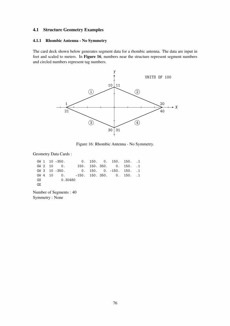
4.1 Structure Geometry Examples
4.1.1 Rhombic Antenna - No Symmetry
The card deck shown below generates segment data for a rhombic antenna. The data are input infeet and scaled to meters. In Figure 16, numbers near the structure represent segment numbersand circled numbers represent tag numbers.
X
Y
1
10 11
20
40
3130
21
1 2
43
UNITS OF 100
Figure 16: Rhombic Antenna - No Symmetry.
Geometry Data Cards :
GW 1 10 -350. 0. 150. 0. 150. 150. .1GW 2 10 0. 150. 150. 350. 0. 150. .1GW 3 10 -350. 0. 150. 0. -150. 150. .1GW 4 10 0. -150. 150. 350. 0. 150. .1GS 0.30480GE
Number of Segments : 40Symmetry : None
76
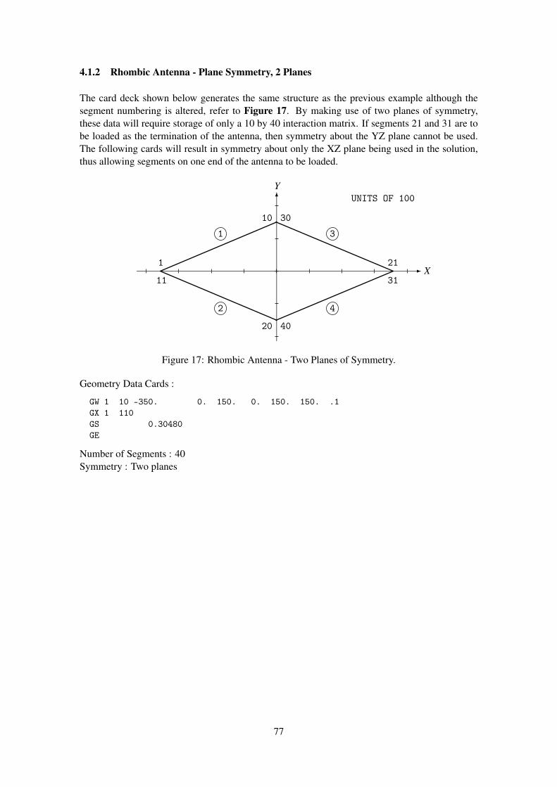
4.1.2 Rhombic Antenna - Plane Symmetry, 2 Planes
The card deck shown below generates the same structure as the previous example although thesegment numbering is altered, refer to Figure 17. By making use of two planes of symmetry,these data will require storage of only a 10 by 40 interaction matrix. If segments 21 and 31 are tobe loaded as the termination of the antenna, then symmetry about the YZ plane cannot be used.The following cards will result in symmetry about only the XZ plane being used in the solution,thus allowing segments on one end of the antenna to be loaded.
X
Y
1
10 30
21
31
4020
11
1 3
42
UNITS OF 100
Figure 17: Rhombic Antenna - Two Planes of Symmetry.
Geometry Data Cards :
GW 1 10 -350. 0. 150. 0. 150. 150. .1GX 1 110GS 0.30480GE
Number of Segments : 40Symmetry : Two planes
77

4.1.3 Rhombic Antenna - Plane Symmetry, 1 Plane
Refer to Figure 18. Segments 1 through 20 of this structure are in the first symmetric section.Hence, segments 11 and 31 can be loaded without loading segments 1 and 21 (Loading segmentsin symmetric structures is discussed in the sub-section covering the LD card). These data willcause storage of a 20 by 40 interaction matrix.
X
Y
1
10 20
11
31
4030
21
1 2
43
UNITS OF 100
Figure 18: Rhombic Antenna - One Plane of Symmetry.
Geometry Data Cards :
GW 1 10 -350. 0. 150. 0. 150. 150. .1GX 1 100GX 2 010GS 0.30480GE
Number of Segments : 40Symmetry : One plane
78

4.1.4 Two Coaxial Rings
The card deck shown below generates segment data for two coaxial rings, refer to Figure 19.The first 45 degree section of the two rings is generated by the first three GW cards. This sectionis then rotated about the X-axis to complete the structure. The rings are then rotated about theX-axis and elevated to produce the structure shown. Since no tag increment is specified on the GRcard, all segments on the first ring have tags of 1 and all segments on the second ring have tagsof 2. Because of symmetry, these data will require storage of only a 3 by 24 interaction matrix.If a 1 were punched in column 5 of the GE card, however, symmetry would be destroyed by theinteraction with the ground, requiring storage of a 24 by 24 matrix.
X
Z
12 12
34
5 6
Figure 19: Coaxial Rings.
Geometry Data Cards :
GW 1 1 1.0 0. 0. 0.70711 0.70711 0. .001GW 2 1 2.0 0. 0. 0.76536 1.84776 0. .001GW 2 1 0.76536 1.84776 0. 1.41421 1.41421 0. .001GR 8GM 90.0 0. 0. 0. 0. 2.0GE
Number of Segments : 24Symmetry : 8 section cylindrical symmetry
79

4.1.5 Linear Antenna over a Wire Grid Plate
The card deck shown below generates segment data for a linear antenna over a wire grid plate,refer to Figure 20. The first 6 cards generate data for the wire grid plate, with the lower left-handcorner at the coordinate origin, by using the GM card to reproduce sections of the structure. TheGM card is then used to move the center of the plate to the origin. Finally, a wire is generated 0.15meters above the plate with a tag of 1.
X
Y
1
1
23
4
56
7
8
9 36
37
38
39 40 41 42 43
Figure 20: Wire Grid Plate and Dipole.
Geometry Data Cards :
GW 1 0. 0. 0. 0.1 0. 0. .001GW 1 0. 0. 0. 0. 0.1 0. .001GM 2 0. 0. 0. 0. 0.1 0.GW 1 0. 0.3 0.0 0.1 0.3 0. .001GM 4 0. 0. 0. 0.1 0. 0.GW 3 0.5 0. 0. 0.5 0.3 0. .001GM 0. 0. 0. -0.25 -0.15 0.GW 1 5 -0.25 0. 0.15 0.25 0. 0.15 .001GE
Number of Segments : 43Symmetry : None
80
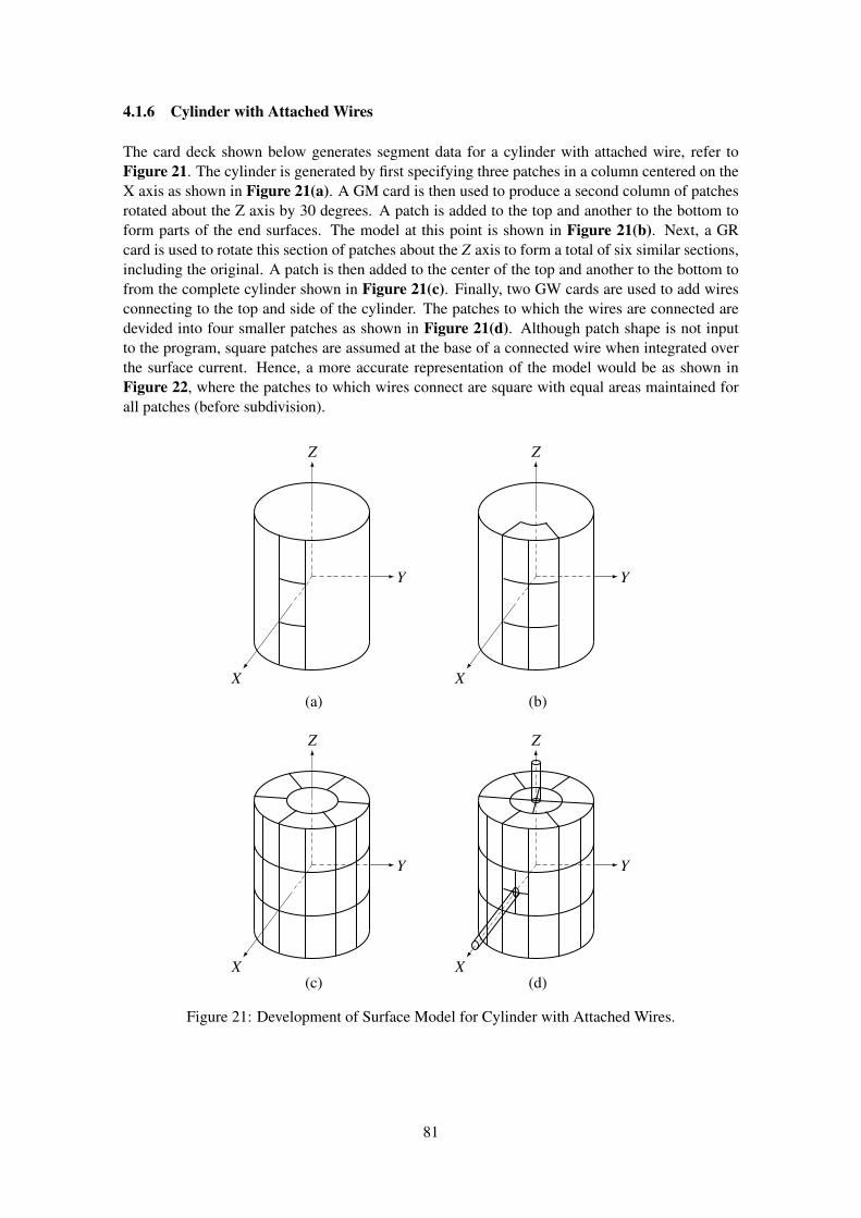
4.1.6 Cylinder with Attached Wires
The card deck shown below generates segment data for a cylinder with attached wire, refer toFigure 21. The cylinder is generated by first specifying three patches in a column centered on theX axis as shown in Figure 21(a). A GM card is then used to produce a second column of patchesrotated about the Z axis by 30 degrees. A patch is added to the top and another to the bottom toform parts of the end surfaces. The model at this point is shown in Figure 21(b). Next, a GRcard is used to rotate this section of patches about the Z axis to form a total of six similar sections,including the original. A patch is then added to the center of the top and another to the bottom tofrom the complete cylinder shown in Figure 21(c). Finally, two GW cards are used to add wiresconnecting to the top and side of the cylinder. The patches to which the wires are connected aredevided into four smaller patches as shown in Figure 21(d). Although patch shape is not inputto the program, square patches are assumed at the base of a connected wire when integrated overthe surface current. Hence, a more accurate representation of the model would be as shown inFigure 22, where the patches to which wires connect are square with equal areas maintained forall patches (before subdivision).
X
Y
Z
(a) (b)
(c) (d)
X
Y
Z
X
Y
Z
X
Y
Z
Figure 21: Development of Surface Model for Cylinder with Attached Wires.
81

Geometry Data Cards :
SP 10. 0. 7.3333 0. 0. 38.4SP 10. 0. 0. 0. 0. 38.4SP 10. 0. 7.3333 0. 0. 38.4GM 1 0. 0. 30.SP 6.89 0. 11. 90. 0. 44.89SP 6.89 0. 11. 90. 0. 44.89GR 6SP 0. 0. 11. 90. 0. 44.89SP 0. 0. 11. 90. 0. 44.89GW 4 0. 0. 11. 0. 0. 23. .1GW 5 10. 0. 0. 27.6 0. 0. .2GS .01GE
Number of Segments : 9Number of Patches : 56Symmetry : None
Figure 22: Segmentation of Cylinder for Wire Connected to End and Side.
82

4.2 Structure Analysis Examples
4.2.1 Center Fed Linear Antenna (Applied-E-Field).
This example includes the calculation of the near-electric-field along a wire. When the field iscomputed at the center of a segment without an applied field or loading, the Z-component ofelectric field is small since the solution procedure enforces the boundary condition at these points.This is a check that the program is operating correctly. The values would be still smaller if the fieldpoints were more precisely at the segment centers. The radial, or X, components of the near-fieldcan also be compared with the charge densities at the segment centers (ρ = 2π aε0 Ex). If the fieldswere computed along the wire axis, the radial field would be set to zero. For a nonplanar structure,however, computation along the axis is the only way to reproduce the conditions of the currentsolution and obtain small fields at the match points.
Input Card Deck :
CEEXAMPLE 1. CENTER FED LINEAR ANTENNAGW 0,7,0.,0.,-.25,0.,0.,.25,.001GEEX 0 0 4 0 1.XQLD 0 0 4 4 10. 3.000E-09 5.300E-11PQNE 0 1 1 15 .001 0 0 0. 0. .01786EN
Line-Printer Output :
83
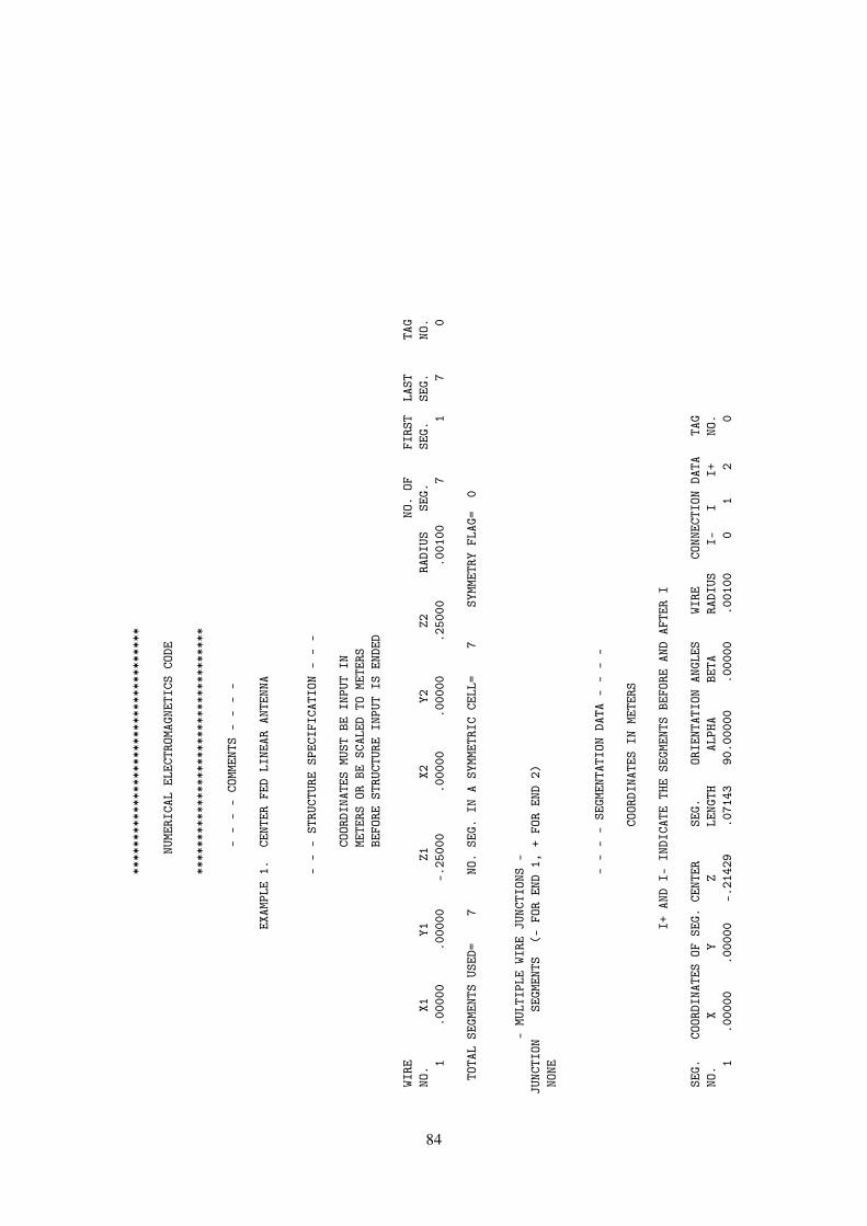
****
****
****
****
****
****
****
****
****
NUME
RICA
LEL
ECTR
OMAG
NETI
CSCO
DE
****
****
****
****
****
****
****
****
****
--
--
COMM
ENTS
--
--
EXAM
PLE
1.CE
NTER
FED
LINE
ARAN
TENN
A
--
-ST
RUCT
URE
SPEC
IFIC
ATIO
N-
--
COOR
DINA
TES
MUST
BEIN
PUT
INME
TERS
ORBE
SCAL
EDTO
METE
RSBE
FORE
STRU
CTUR
EIN
PUT
ISEN
DED
WIRE
NO.
OFFI
RST
LAST
TAG
NO.
X1Y1
Z1X2
Y2Z2
RADI
USSE
G.SE
G.SE
G.NO
.1
.000
00.0
0000
-.25
000
.000
00.0
0000
.250
00.0
0100
71
70
TOTA
LSE
GMEN
TSUS
ED=
7NO
.SE
G.IN
ASY
MMET
RIC
CELL
=7
SYMM
ETRY
FLAG
=0
-MU
LTIP
LEWI
REJU
NCTI
ONS
-JU
NCTI
ONSE
GMEN
TS(-
FOR
END
1,+
FOR
END
2)NO
NE
--
--
SEGM
ENTA
TION
DATA
--
--
COOR
DINA
TES
INME
TERS
I+AN
DI-
INDI
CATE
THE
SEGM
ENTS
BEFO
REAN
DAF
TER
I
SEG.
COOR
DINA
TES
OFSE
G.CE
NTER
SEG.
ORIE
NTAT
ION
ANGL
ESWI
RECO
NNEC
TION
DATA
TAG
NO.
XY
ZLE
NGTH
ALPH
ABE
TARA
DIUS
I-I
I+NO
.1
.000
00.0
0000
-.21
429
.071
4390
.000
00.0
0000
.001
000
12
0
84
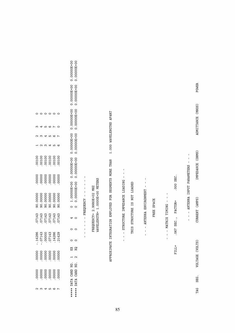
2.0
0000
.000
00-.
1428
6.0
7143
90.0
0000
.000
00.0
0100
12
30
3.0
0000
.000
00-.
0714
3.0
7143
90.0
0000
.000
00.0
0100
23
40
4.0
0000
.000
00.0
0000
.071
4390
.000
00.0
0000
.001
003
45
05
.000
00.0
0000
.071
43.0
7143
90.0
0000
.000
00.0
0100
45
60
6.0
0000
.000
00.1
4286
.071
4390
.000
00.0
0000
.001
005
67
07
.000
00.0
0000
.214
29.0
7143
90.0
0000
.000
00.0
0100
67
00
****
*DA
TACA
RDNO
.1
EX0
04
01.
0000
0E+0
00.
0000
0E+0
00.
0000
0E+0
00.
0000
0E+0
00.
0000
0E+0
00.
0000
0E+0
0**
***
DATA
CARD
NO.
2XQ
00
00
0.00
000E
+00
0.00
000E
+00
0.00
000E
+00
0.00
000E
+00
0.00
000E
+00
0.00
000E
+00
--
--
--
FREQ
UENC
Y-
--
--
-
FREQ
UENC
Y=2.
9980
E+02
MHZ
WAVE
LENG
TH=
1.00
00E+
00ME
TERS
APPR
OXIM
ATE
INTE
GRAT
ION
EMPL
OYED
FOR
SEGM
ENTS
MORE
THAN
1.00
0WA
VELE
NGTH
SAP
ART
--
-ST
RUCT
URE
IMPE
DANC
ELO
ADIN
G-
--
THIS
STRU
CTUR
EIS
NOT
LOAD
ED
--
-AN
TENN
AEN
VIRO
NMEN
T-
--
FREE
SPAC
E
--
-MA
TRIX
TIMI
NG-
--
FILL
=.0
67SE
C.,
FACT
OR=
.000
SEC.
--
-AN
TENN
AIN
PUT
PARA
METE
RS-
--
TAG
SEG.
VOLT
AGE
(VOL
TS)
CURR
ENT
(AMP
S)IM
PEDA
NCE
(OHM
S)AD
MITT
ANCE
(MHO
S)PO
WER
85
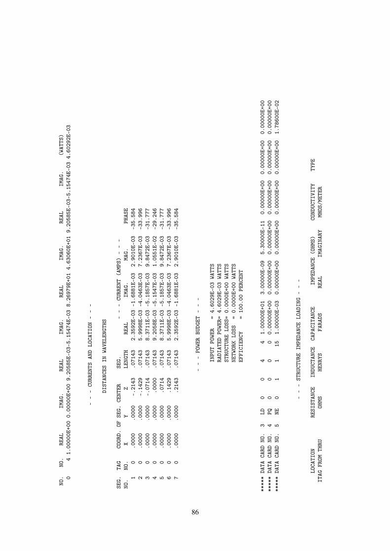
NO.
NO.
REAL
IMAG
.RE
ALIM
AG.
REAL
IMAG
.RE
ALIM
AG.
(WAT
TS)
04
1.00
000E
+00
0.00
000E
+00
9.20
585E
-03-
5.15
474E
-03
8.26
979E
+01
4.63
060E
+01
9.20
585E
-03-
5.15
474E
-03
4.60
292E
-03
--
-CU
RREN
TSAN
DLO
CATI
ON-
--
DIST
ANCE
SIN
WAVE
LENG
THS
SEG.
TAG
COOR
D.OF
SEG.
CENT
ERSE
G.-
--
CURR
ENT
(AMP
S)-
--
NO.
NO.
XY
ZLE
NGTH
REAL
IMAG
.MA
G.PH
ASE
10
.000
0.0
000
-.21
43.0
7143
2.35
92E-
03-1
.688
1E-0
32.
9010
E-03
-35.
584
20
.000
0.0
000
-.14
29.0
7143
5.99
98E-
03-4
.046
3E-0
37.
2367
E-03
-33.
996
30
.000
0.0
000
-.07
14.0
7143
8.37
11E-
03-5
.185
7E-0
39.
8472
E-03
-31.
777
40
.000
0.0
000
.000
0.0
7143
9.20
58E-
03-5
.154
7E-0
31.
0551
E-02
-29.
246
50
.000
0.0
000
.071
4.0
7143
8.37
11E-
03-5
.185
7E-0
39.
8472
E-03
-31.
777
60
.000
0.0
000
.142
9.0
7143
5.99
98E-
03-4
.046
3E-0
37.
2367
E-03
-33.
996
70
.000
0.0
000
.214
3.0
7143
2.35
92E-
03-1
.688
1E-0
32.
9010
E-03
-35.
584
--
-PO
WER
BUDG
ET-
--
INPU
TPO
WER
=4.
6029
E-03
WATT
SRA
DIAT
EDPO
WER=
4.60
29E-
03WA
TTS
STRU
CTUR
ELO
SS=
0.00
00E+
00WA
TTS
NETW
ORK
LOSS
=0.
0000
E+00
WATT
SEF
FICI
ENCY
=10
0.00
PERC
ENT
****
*DA
TACA
RDNO
.3
LD0
04
41.
0000
0E+0
13.
0000
0E-0
95.
3000
0E-1
10.
0000
0E+0
00.
0000
0E+0
00.
0000
0E+0
0**
***
DATA
CARD
NO.
4PQ
00
00
0.00
000E
+00
0.00
000E
+00
0.00
000E
+00
0.00
000E
+00
0.00
000E
+00
0.00
000E
+00
****
*DA
TACA
RDNO
.5
NE0
11
151.
0000
0E-0
30.
0000
0E+0
00.
0000
0E+0
00.
0000
0E+0
00.
0000
0E+0
01.
7860
0E-0
2
--
-ST
RUCT
URE
IMPE
DANC
ELO
ADIN
G-
--
LOCA
TION
RESI
STAN
CEIN
DUCT
ANCE
CAPA
CITA
NCE
IMPE
DANC
E(O
HMS)
COND
UCTI
VITY
TYPE
ITAG
FROM
THRU
OHMS
HENR
YSFA
RADS
REAL
IMAG
INAR
YMH
OS/M
ETER
86
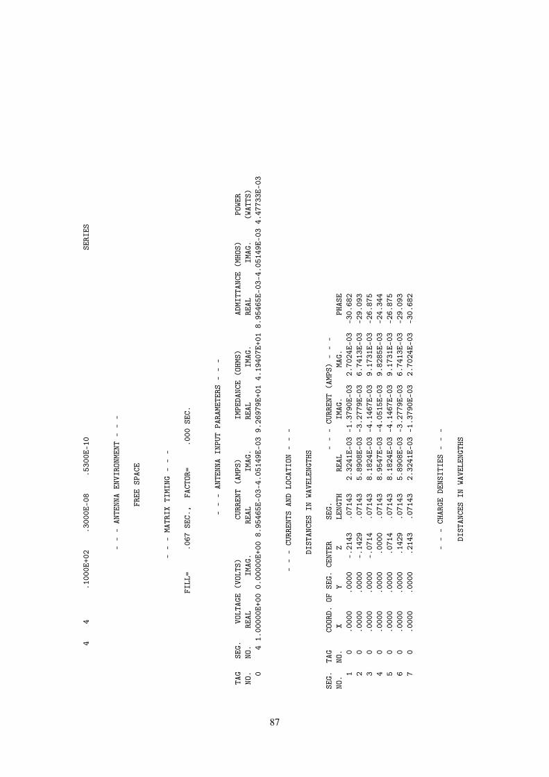
44
.100
0E+0
2.3
000E
-08
.530
0E-1
0SE
RIES
--
-AN
TENN
AEN
VIRO
NMEN
T-
--
FREE
SPAC
E
--
-MA
TRIX
TIMI
NG-
--
FILL
=.0
67SE
C.,
FACT
OR=
.000
SEC.
--
-AN
TENN
AIN
PUT
PARA
METE
RS-
--
TAG
SEG.
VOLT
AGE
(VOL
TS)
CURR
ENT
(AMP
S)IM
PEDA
NCE
(OHM
S)AD
MITT
ANCE
(MHO
S)PO
WER
NO.
NO.
REAL
IMAG
.RE
ALIM
AG.
REAL
IMAG
.RE
ALIM
AG.
(WAT
TS)
04
1.00
000E
+00
0.00
000E
+00
8.95
465E
-03-
4.05
149E
-03
9.26
979E
+01
4.19
407E
+01
8.95
465E
-03-
4.05
149E
-03
4.47
733E
-03
--
-CU
RREN
TSAN
DLO
CATI
ON-
--
DIST
ANCE
SIN
WAVE
LENG
THS
SEG.
TAG
COOR
D.OF
SEG.
CENT
ERSE
G.-
--
CURR
ENT
(AMP
S)-
--
NO.
NO.
XY
ZLE
NGTH
REAL
IMAG
.MA
G.PH
ASE
10
.000
0.0
000
-.21
43.0
7143
2.32
41E-
03-1
.379
0E-0
32.
7024
E-03
-30.
682
20
.000
0.0
000
-.14
29.0
7143
5.89
08E-
03-3
.277
9E-0
36.
7413
E-03
-29.
093
30
.000
0.0
000
-.07
14.0
7143
8.18
24E-
03-4
.146
7E-0
39.
1731
E-03
-26.
875
40
.000
0.0
000
.000
0.0
7143
8.95
47E-
03-4
.051
5E-0
39.
8285
E-03
-24.
344
50
.000
0.0
000
.071
4.0
7143
8.18
24E-
03-4
.146
7E-0
39.
1731
E-03
-26.
875
60
.000
0.0
000
.142
9.0
7143
5.89
08E-
03-3
.277
9E-0
36.
7413
E-03
-29.
093
70
.000
0.0
000
.214
3.0
7143
2.32
41E-
03-1
.379
0E-0
32.
7024
E-03
-30.
682
--
-CH
ARGE
DENS
ITIE
S-
--
DIST
ANCE
SIN
WAVE
LENG
THS
87

SEG.
TAG
COOR
D.OF
SEG.
CENT
ERSE
G.CH
ARGE
DENS
ITY
(COU
LOMB
S/ME
TER)
NO.
NO.
XY
ZLE
NGTH
REAL
IMAG
.MA
G.PH
ASE
10
.000
0.0
000
-.21
43.0
7143
1.82
92E-
113.
1761
E-11
3.66
52E-
1160
.061
20
.000
0.0
000
-.14
29.0
7143
1.04
29E-
112.
2040
E-11
2.43
83E-
1164
.676
30
.000
0.0
000
-.07
14.0
7143
2.11
40E-
121.
1638
E-11
1.18
29E-
1179
.705
40
.000
0.0
000
.000
0.0
7143
5.16
84E-
192.
3814
E-19
5.69
06E-
1924
.738
50
.000
0.0
000
.071
4.0
7143
-2.1
140E
-12
-1.1
638E
-11
1.18
29E-
11-1
00.2
956
0.0
000
.000
0.1
429
.071
43-1
.042
9E-1
1-2
.204
0E-1
12.
4383
E-11
-115
.324
70
.000
0.0
000
.214
3.0
7143
-1.8
292E
-11
-3.1
761E
-11
3.66
52E-
11-1
19.9
39
--
-PO
WER
BUDG
ET-
--
INPU
TPO
WER
=4.
4773
E-03
WATT
SRA
DIAT
EDPO
WER=
3.99
43E-
03WA
TTS
STRU
CTUR
ELO
SS=
4.83
00E-
04WA
TTS
NETW
ORK
LOSS
=0.
0000
E+00
WATT
SEF
FICI
ENCY
=89
.21
PERC
ENT
--
-NE
AREL
ECTR
ICFI
ELDS
--
-
-LO
CATI
ON-
-EX
--
EY-
-EZ
-X
YZ
MAGN
ITUD
EPH
ASE
MAGN
ITUD
EPH
ASE
MAGN
ITUD
EPH
ASE
METE
RSME
TERS
METE
RSVO
LTS/
MDE
GREE
SVO
LTS/
MDE
GREE
SVO
LTS/
MDE
GREE
S.0
010
.000
0.0
000
1.02
28E-
0524
.74
0.00
00E+
00.0
01.
3042
E+01
-175
.10
.001
0.0
000
.017
95.
5442
E+01
-66.
310.
0000
E+00
.00
1.25
37E+
01-1
75.0
8.0
010
.000
0.0
357
1.09
68E+
02-6
7.15
0.00
00E+
00.0
06.
7271
E+00
-175
.46
.001
0.0
000
.053
61.
5608
E+02
-88.
850.
0000
E+00
.00
8.43
39E-
01-1
79.7
5.0
010
.000
0.0
714
2.12
67E+
02-1
00.3
00.
0000
E+00
.00
4.21
35E-
04-6
.13
.001
0.0
000
.089
32.
7147
E+02
-106
.86
0.00
00E+
00.0
03.
4497
E-01
-8.8
7.0
010
.000
0.1
072
3.29
20E+
02-1
11.0
80.
0000
E+00
.00
2.80
00E-
0122
.83
.001
0.0
000
.125
03.
8592
E+02
-113
.51
0.00
00E+
00.0
02.
2076
E-01
74.4
1.0
010
.000
0.1
429
4.38
35E+
02-1
15.3
30.
0000
E+00
.00
3.09
05E-
04-9
4.14
.001
0.0
000
.160
74.
8563
E+02
-116
.77
0.00
00E+
00.0
02.
1937
E-01
-106
.41
.001
0.0
000
.178
65.
2800
E+02
-117
.97
0.00
00E+
00.0
01.
9750
E+00
57.5
7.0
010
.000
0.1
965
5.96
64E+
02-1
19.0
60.
0000
E+00
.00
3.31
13E+
0058
.63
88

.001
0.0
000
.214
36.
5880
E+02
-119
.94
0.00
00E+
00.0
09.
9556
E-03
-121
.24
.001
0.0
000
.232
27.
1246
E+02
-120
.67
0.00
00E+
00.0
01.
0680
E+01
-121
.66
.001
0.0
000
.250
05.
5195
E+02
-121
.29
0.00
00E+
00.0
03.
8032
E+02
-121
.43
****
*DA
TACA
RDNO
.6
EN0
00
00.
0000
0E+0
00.
0000
0E+0
00.
0000
0E+0
00.
0000
0E+0
00.
0000
0E+0
00.
0000
0E+0
0
RUN
TIME
=.6
50
89
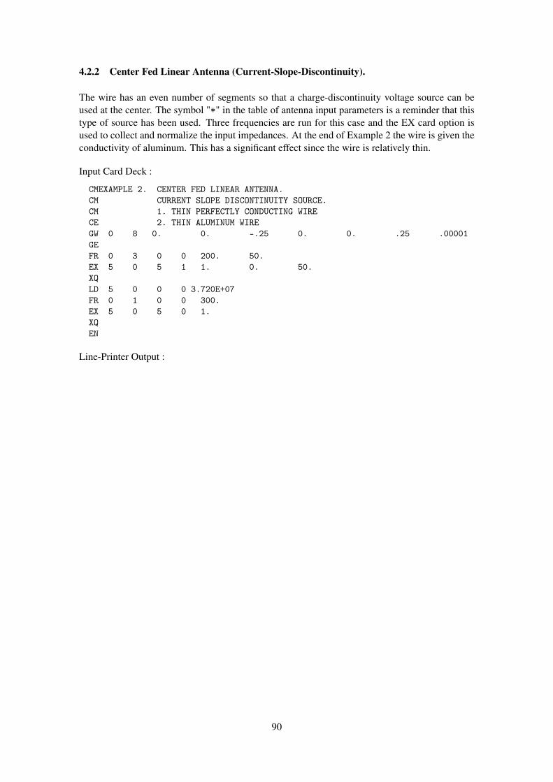
4.2.2 Center Fed Linear Antenna (Current-Slope-Discontinuity).
The wire has an even number of segments so that a charge-discontinuity voltage source can beused at the center. The symbol "*" in the table of antenna input parameters is a reminder that thistype of source has been used. Three frequencies are run for this case and the EX card option isused to collect and normalize the input impedances. At the end of Example 2 the wire is given theconductivity of aluminum. This has a significant effect since the wire is relatively thin.
Input Card Deck :
CMEXAMPLE 2. CENTER FED LINEAR ANTENNA.CM CURRENT SLOPE DISCONTINUITY SOURCE.CM 1. THIN PERFECTLY CONDUCTING WIRECE 2. THIN ALUMINUM WIREGW 0 8 0. 0. -.25 0. 0. .25 .00001GEFR 0 3 0 0 200. 50.EX 5 0 5 1 1. 0. 50.XQLD 5 0 0 0 3.720E+07FR 0 1 0 0 300.EX 5 0 5 0 1.XQEN
Line-Printer Output :
90

****
****
****
****
****
****
****
****
****
NUME
RICA
LEL
ECTR
OMAG
NETI
CSCO
DE
****
****
****
****
****
****
****
****
****
--
--
COMM
ENTS
--
--
EXAM
PLE
2.CE
NTER
FED
LINE
ARAN
TENN
A.CU
RREN
TSL
OPE
DISC
ONTI
NUIT
YSO
URCE
.1.
THIN
PERF
ECTL
YCO
NDUC
TING
WIRE
2.TH
INAL
UMIN
UMWI
RE
--
-ST
RUCT
URE
SPEC
IFIC
ATIO
N-
--
COOR
DINA
TES
MUST
BEIN
PUT
INME
TERS
ORBE
SCAL
EDTO
METE
RSBE
FORE
STRU
CTUR
EIN
PUT
ISEN
DED
WIRE
NO.
OFFI
RST
LAST
TAG
NO.
X1Y1
Z1X2
Y2Z2
RADI
USSE
G.SE
G.SE
G.NO
.1
.000
00.0
0000
-.25
000
.000
00.0
0000
.250
00.0
0001
81
80
TOTA
LSE
GMEN
TSUS
ED=
8NO
.SE
G.IN
ASY
MMET
RIC
CELL
=8
SYMM
ETRY
FLAG
=0
-MU
LTIP
LEWI
REJU
NCTI
ONS
-JU
NCTI
ONSE
GMEN
TS(-
FOR
END
1,+
FOR
END
2)NO
NE
--
--
SEGM
ENTA
TION
DATA
--
--
COOR
DINA
TES
INME
TERS
I+AN
DI-
INDI
CATE
THE
SEGM
ENTS
BEFO
REAN
DAF
TER
I
91

SEG.
COOR
DINA
TES
OFSE
G.CE
NTER
SEG.
ORIE
NTAT
ION
ANGL
ESWI
RECO
NNEC
TION
DATA
TAG
NO.
XY
ZLE
NGTH
ALPH
ABE
TARA
DIUS
I-I
I+NO
.1
.000
00.0
0000
-.21
875
.062
5090
.000
00.0
0000
.000
010
12
02
.000
00.0
0000
-.15
625
.062
5090
.000
00.0
0000
.000
011
23
03
.000
00.0
0000
-.09
375
.062
5090
.000
00.0
0000
.000
012
34
04
.000
00.0
0000
-.03
125
.062
5090
.000
00.0
0000
.000
013
45
05
.000
00.0
0000
.031
25.0
6250
90.0
0000
.000
00.0
0001
45
60
6.0
0000
.000
00.0
9375
.062
5090
.000
00.0
0000
.000
015
67
07
.000
00.0
0000
.156
25.0
6250
90.0
0000
.000
00.0
0001
67
80
8.0
0000
.000
00.2
1875
.062
5090
.000
00.0
0000
.000
017
80
0
****
*DA
TACA
RDNO
.1
FR0
30
02.
0000
0E+0
25.
0000
0E+0
10.
0000
0E+0
00.
0000
0E+0
00.
0000
0E+0
00.
0000
0E+0
0**
***
DATA
CARD
NO.
2EX
50
51
1.00
000E
+00
0.00
000E
+00
5.00
000E
+01
0.00
000E
+00
0.00
000E
+00
0.00
000E
+00
****
*DA
TACA
RDNO
.3
XQ0
00
00.
0000
0E+0
00.
0000
0E+0
00.
0000
0E+0
00.
0000
0E+0
00.
0000
0E+0
00.
0000
0E+0
0
--
--
--
FREQ
UENC
Y-
--
--
-
FREQ
UENC
Y=2.
0000
E+02
MHZ
WAVE
LENG
TH=
1.49
90E+
00ME
TERS
APPR
OXIM
ATE
INTE
GRAT
ION
EMPL
OYED
FOR
SEGM
ENTS
MORE
THAN
1.00
0WA
VELE
NGTH
SAP
ART
--
-ST
RUCT
URE
IMPE
DANC
ELO
ADIN
G-
--
THIS
STRU
CTUR
EIS
NOT
LOAD
ED
--
-AN
TENN
AEN
VIRO
NMEN
T-
--
FREE
SPAC
E
--
-MA
TRIX
TIMI
NG-
--
92
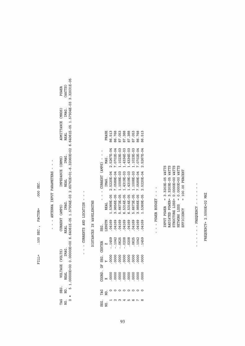
FILL
=.1
00SE
C.,
FACT
OR=
.000
SEC.
--
-AN
TENN
AIN
PUT
PARA
METE
RS-
--
TAG
SEG.
VOLT
AGE
(VOL
TS)
CURR
ENT
(AMP
S)IM
PEDA
NCE
(OHM
S)AD
MITT
ANCE
(MHO
S)PO
WER
NO.
NO.
REAL
IMAG
.RE
ALIM
AG.
REAL
IMAG
.RE
ALIM
AG.
(WAT
TS)
0*
51.
0000
0E+0
00.
0000
0E+0
06.
6406
1E-0
51.
5793
4E-0
32.
6576
2E+0
1-6.
3206
0E+0
26.
6406
1E-0
51.
5793
4E-0
33.
3203
1E-0
5
--
-CU
RREN
TSAN
DLO
CATI
ON-
--
DIST
ANCE
SIN
WAVE
LENG
THS
SEG.
TAG
COOR
D.OF
SEG.
CENT
ERSE
G.-
--
CURR
ENT
(AMP
S)-
--
NO.
NO.
XY
ZLE
NGTH
REAL
IMAG
.MA
G.PH
ASE
10
.000
0.0
000
-.14
59.0
4169
1.53
69E-
052.
5220
E-04
2.52
67E-
0486
.513
20
.000
0.0
000
-.10
42.0
4169
3.98
56E-
057.
0589
E-04
7.07
02E-
0486
.768
30
.000
0.0
000
-.06
25.0
4169
5.66
73E-
051.
1008
E-03
1.10
23E-
0387
.053
40
.000
0.0
000
-.02
08.0
4169
6.53
14E-
051.
4319
E-03
1.43
34E-
0387
.388
50
.000
0.0
000
.020
8.0
4169
6.53
14E-
051.
4319
E-03
1.43
34E-
0387
.388
60
.000
0.0
000
.062
5.0
4169
5.66
73E-
051.
1008
E-03
1.10
23E-
0387
.053
70
.000
0.0
000
.104
2.0
4169
3.98
56E-
057.
0589
E-04
7.07
02E-
0486
.768
80
.000
0.0
000
.145
9.0
4169
1.53
69E-
052.
5220
E-04
2.52
67E-
0486
.513
--
-PO
WER
BUDG
ET-
--
INPU
TPO
WER
=3.
3203
E-05
WATT
SRA
DIAT
EDPO
WER=
3.32
03E-
05WA
TTS
STRU
CTUR
ELO
SS=
0.00
00E+
00WA
TTS
NETW
ORK
LOSS
=0.
0000
E+00
WATT
SEF
FICI
ENCY
=10
0.00
PERC
ENT
--
--
--
FREQ
UENC
Y-
--
--
-
FREQ
UENC
Y=2.
5000
E+02
MHZ
93

WAVE
LENG
TH=
1.19
92E+
00ME
TERS
APPR
OXIM
ATE
INTE
GRAT
ION
EMPL
OYED
FOR
SEGM
ENTS
MORE
THAN
1.00
0WA
VELE
NGTH
SAP
ART
--
-ST
RUCT
URE
IMPE
DANC
ELO
ADIN
G-
--
THIS
STRU
CTUR
EIS
NOT
LOAD
ED
--
-AN
TENN
AEN
VIRO
NMEN
T-
--
FREE
SPAC
E
--
-MA
TRIX
TIMI
NG-
--
FILL
=.1
00SE
C.,
FACT
OR=
.000
SEC.
--
-AN
TENN
AIN
PUT
PARA
METE
RS-
--
TAG
SEG.
VOLT
AGE
(VOL
TS)
CURR
ENT
(AMP
S)IM
PEDA
NCE
(OHM
S)AD
MITT
ANCE
(MHO
S)PO
WER
NO.
NO.
REAL
IMAG
.RE
ALIM
AG.
REAL
IMAG
.RE
ALIM
AG.
(WAT
TS)
0*
51.
0000
0E+0
00.
0000
0E+0
06.
1698
4E-0
43.
5646
6E-0
34.
7143
1E+0
1-2.
7237
2E+0
26.
1698
4E-0
43.
5646
6E-0
33.
0849
2E-0
4
--
-CU
RREN
TSAN
DLO
CATI
ON-
--
DIST
ANCE
SIN
WAVE
LENG
THS
SEG.
TAG
COOR
D.OF
SEG.
CENT
ERSE
G.-
--
CURR
ENT
(AMP
S)-
--
NO.
NO.
XY
ZLE
NGTH
REAL
IMAG
.MA
G.PH
ASE
10
.000
0.0
000
-.18
24.0
5212
1.36
29E-
046.
4701
E-04
6.61
20E-
0478
.105
20
.000
0.0
000
-.13
03.0
5212
3.61
69E-
041.
7863
E-03
1.82
25E-
0378
.553
30
.000
0.0
000
-.07
82.0
5212
5.22
15E-
042.
7057
E-03
2.75
57E-
0379
.077
40
.000
0.0
000
-.02
61.0
5212
6.06
27E-
043.
3503
E-03
3.40
47E-
0379
.743
94

50
.000
0.0
000
.026
1.0
5212
6.06
27E-
043.
3503
E-03
3.40
47E-
0379
.743
60
.000
0.0
000
.078
2.0
5212
5.22
15E-
042.
7057
E-03
2.75
57E-
0379
.077
70
.000
0.0
000
.130
3.0
5212
3.61
69E-
041.
7863
E-03
1.82
25E-
0378
.553
80
.000
0.0
000
.182
4.0
5212
1.36
29E-
046.
4701
E-04
6.61
20E-
0478
.105
--
-PO
WER
BUDG
ET-
--
INPU
TPO
WER
=3.
0849
E-04
WATT
SRA
DIAT
EDPO
WER=
3.08
49E-
04WA
TTS
STRU
CTUR
ELO
SS=
0.00
00E+
00WA
TTS
NETW
ORK
LOSS
=0.
0000
E+00
WATT
SEF
FICI
ENCY
=10
0.00
PERC
ENT
--
--
--
FREQ
UENC
Y-
--
--
-
FREQ
UENC
Y=3.
0000
E+02
MHZ
WAVE
LENG
TH=
9.99
33E-
01ME
TERS
APPR
OXIM
ATE
INTE
GRAT
ION
EMPL
OYED
FOR
SEGM
ENTS
MORE
THAN
1.00
0WA
VELE
NGTH
SAP
ART
--
-ST
RUCT
URE
IMPE
DANC
ELO
ADIN
G-
--
THIS
STRU
CTUR
EIS
NOT
LOAD
ED
--
-AN
TENN
AEN
VIRO
NMEN
T-
--
FREE
SPAC
E
--
-MA
TRIX
TIMI
NG-
--
FILL
=.1
00SE
C.,
FACT
OR=
.000
SEC.
95

--
-AN
TENN
AIN
PUT
PARA
METE
RS-
--
TAG
SEG.
VOLT
AGE
(VOL
TS)
CURR
ENT
(AMP
S)IM
PEDA
NCE
(OHM
S)AD
MITT
ANCE
(MHO
S)PO
WER
NO.
NO.
REAL
IMAG
.RE
ALIM
AG.
REAL
IMAG
.RE
ALIM
AG.
(WAT
TS)
0*
51.
0000
0E+0
00.
0000
0E+0
09.
3901
2E-0
3-5.
3290
9E-0
38.
0551
1E+0
14.
5714
4E+0
19.
3901
2E-0
3-5.
3290
9E-0
34.
6950
6E-0
3
--
-CU
RREN
TSAN
DLO
CATI
ON-
--
DIST
ANCE
SIN
WAVE
LENG
THS
SEG.
TAG
COOR
D.OF
SEG.
CENT
ERSE
G.-
--
CURR
ENT
(AMP
S)-
--
NO.
NO.
XY
ZLE
NGTH
REAL
IMAG
.MA
G.PH
ASE
10
.000
0.0
000
-.21
89.0
6254
1.96
07E-
03-1
.279
9E-0
32.
3415
E-03
-33.
135
20
.000
0.0
000
-.15
64.0
6254
5.35
17E-
03-3
.403
3E-0
36.
3422
E-03
-32.
454
30
.000
0.0
000
-.09
38.0
6254
7.86
78E-
03-4
.842
1E-0
39.
2384
E-03
-31.
610
40
.000
0.0
000
-.03
13.0
6254
9.21
68E-
03-5
.414
7E-0
31.
0690
E-02
-30.
433
50
.000
0.0
000
.031
3.0
6254
9.21
68E-
03-5
.414
7E-0
31.
0690
E-02
-30.
433
60
.000
0.0
000
.093
8.0
6254
7.86
78E-
03-4
.842
1E-0
39.
2384
E-03
-31.
610
70
.000
0.0
000
.156
4.0
6254
5.35
17E-
03-3
.403
3E-0
36.
3422
E-03
-32.
454
80
.000
0.0
000
.218
9.0
6254
1.96
07E-
03-1
.279
9E-0
32.
3415
E-03
-33.
135
--
-PO
WER
BUDG
ET-
--
INPU
TPO
WER
=4.
6951
E-03
WATT
SRA
DIAT
EDPO
WER=
4.69
51E-
03WA
TTS
STRU
CTUR
ELO
SS=
0.00
00E+
00WA
TTS
NETW
ORK
LOSS
=0.
0000
E+00
WATT
SEF
FICI
ENCY
=10
0.00
PERC
ENT
--
-IN
PUT
IMPE
DANC
EDA
TA-
--
SOUR
CESE
GMEN
TNO
.5
NORM
ALIZ
ATIO
NFA
CTOR
=5.
0000
0E+0
1
FREQ
.-
-UN
NORM
ALIZ
EDIM
PEDA
NCE
--
--
NORM
ALIZ
EDIM
PEDA
NCE
--
96

RESI
STAN
CERE
ACTA
NCE
MAGN
ITUD
EPH
ASE
RESI
STAN
CERE
ACTA
NCE
MAGN
ITUD
EPH
ASE
MHZ
OHMS
OHMS
OHMS
DEGR
EES
DEGR
EES
200.
000
2.65
762E
+01
-6.3
2060
E+02
6.32
619E
+02
-87.
595.
3152
3E-0
1-1
.264
12E+
011.
2652
4E+0
1-8
7.59
250.
000
4.71
431E
+01
-2.7
2372
E+02
2.76
422E
+02
-80.
189.
4286
2E-0
1-5
.447
44E+
005.
5284
3E+0
0-8
0.18
300.
000
8.05
511E
+01
4.57
144E
+01
9.26
190E
+01
29.5
81.
6110
2E+0
09.
1428
9E-0
11.
8523
8E+0
029
.58
****
*DA
TACA
RDNO
.4
LD5
00
03.
7200
0E+0
70.
0000
0E+0
00.
0000
0E+0
00.
0000
0E+0
00.
0000
0E+0
00.
0000
0E+0
0**
***
DATA
CARD
NO.
5FR
01
00
3.00
000E
+02
0.00
000E
+00
0.00
000E
+00
0.00
000E
+00
0.00
000E
+00
0.00
000E
+00
****
*DA
TACA
RDNO
.6
EX5
05
01.
0000
0E+0
00.
0000
0E+0
00.
0000
0E+0
00.
0000
0E+0
00.
0000
0E+0
00.
0000
0E+0
0**
***
DATA
CARD
NO.
7XQ
00
00
0.00
000E
+00
0.00
000E
+00
0.00
000E
+00
0.00
000E
+00
0.00
000E
+00
0.00
000E
+00
--
--
--
FREQ
UENC
Y-
--
--
-
FREQ
UENC
Y=3.
0000
E+02
MHZ
WAVE
LENG
TH=
9.99
33E-
01ME
TERS
APPR
OXIM
ATE
INTE
GRAT
ION
EMPL
OYED
FOR
SEGM
ENTS
MORE
THAN
1.00
0WA
VELE
NGTH
SAP
ART
--
-ST
RUCT
URE
IMPE
DANC
ELO
ADIN
G-
--
LOCA
TION
RESI
STAN
CEIN
DUCT
ANCE
CAPA
CITA
NCE
IMPE
DANC
E(O
HMS)
COND
UCTI
VITY
TYPE
ITAG
FROM
THRU
OHMS
HENR
YSFA
RADS
REAL
IMAG
INAR
YMH
OS/M
ETER
ALL
.372
0E+0
8WI
RE
--
-AN
TENN
AEN
VIRO
NMEN
T-
--
FREE
SPAC
E
--
-MA
TRIX
TIMI
NG-
--
97

FILL
=.1
00SE
C.,
FACT
OR=
.000
SEC.
--
-AN
TENN
AIN
PUT
PARA
METE
RS-
--
TAG
SEG.
VOLT
AGE
(VOL
TS)
CURR
ENT
(AMP
S)IM
PEDA
NCE
(OHM
S)AD
MITT
ANCE
(MHO
S)PO
WER
NO.
NO.
REAL
IMAG
.RE
ALIM
AG.
REAL
IMAG
.RE
ALIM
AG.
(WAT
TS)
0*
51.
0000
0E+0
00.
0000
0E+0
06.
6443
1E-0
3-3.
8666
0E-0
31.
1243
0E+0
26.
5427
6E+0
16.
6443
1E-0
3-3.
8666
0E-0
33.
3221
5E-0
3
--
-CU
RREN
TSAN
DLO
CATI
ON-
--
DIST
ANCE
SIN
WAVE
LENG
THS
SEG.
TAG
COOR
D.OF
SEG.
CENT
ERSE
G.-
--
CURR
ENT
(AMP
S)-
--
NO.
NO.
XY
ZLE
NGTH
REAL
IMAG
.MA
G.PH
ASE
10
.000
0.0
000
-.21
89.0
6254
1.38
62E-
03-9
.630
5E-0
41.
6879
E-03
-34.
790
20
.000
0.0
000
-.15
64.0
6254
3.78
48E-
03-2
.554
6E-0
34.
5663
E-03
-34.
018
30
.000
0.0
000
-.09
38.0
6254
5.56
58E-
03-3
.609
1E-0
36.
6336
E-03
-32.
961
40
.000
0.0
000
-.03
13.0
6254
6.52
15E-
03-3
.978
2E-0
37.
6392
E-03
-31.
384
50
.000
0.0
000
.031
3.0
6254
6.52
15E-
03-3
.978
2E-0
37.
6392
E-03
-31.
384
60
.000
0.0
000
.093
8.0
6254
5.56
58E-
03-3
.609
1E-0
36.
6336
E-03
-32.
961
70
.000
0.0
000
.156
4.0
6254
3.78
48E-
03-2
.554
6E-0
34.
5663
E-03
-34.
018
80
.000
0.0
000
.218
9.0
6254
1.38
62E-
03-9
.630
5E-0
41.
6879
E-03
-34.
790
--
-PO
WER
BUDG
ET-
--
INPU
TPO
WER
=3.
3222
E-03
WATT
SRA
DIAT
EDPO
WER=
2.44
02E-
03WA
TTS
STRU
CTUR
ELO
SS=
8.81
99E-
04WA
TTS
NETW
ORK
LOSS
=0.
0000
E+00
WATT
SEF
FICI
ENCY
=73
.45
PERC
ENT
****
*DA
TACA
RDNO
.8
EN0
00
00.
0000
0E+0
00.
0000
0E+0
00.
0000
0E+0
00.
0000
0E+0
00.
0000
0E+0
00.
0000
0E+0
0
RUN
TIME
=.8
50
98

4.2.3 Vertical Half Wavelength Antenna Over Ground.
Is a vertical dipole over ground. Since the wire is thick the extended thin-wire approximation hasbeen used. Computation of the average power gain is requested on the RP cards. Over a perfectlyconductive ground the average power gain should be 2. The computed result differs by about 1.5%,probably due to the 10-degree steps used in integrating the radiated power. For a more complexstructure, the average gain can provide a check on the accuracy of the computed input impedanceover a perfect ground where it should equal 2 or in free space where it should equal 1. Example 3also includes a finitely conducting ground where the average gain of 0.72 indicates that only 36%of the power leaving the antenna is going into the space wave. The formats for normalized gainand the combined space-wave and ground-wave fields are illustrated. At the end of example 3, thewire is excited with an incident wave at 10-degree angles and the PT card option is used to printreceiving antenna patterns.
Input Card Deck :
CMEXAMPLE 3. VERTICAL HALF WAVELENGTH ANTENNA OVER GROUNDCM EXTENDED THIN WIRE KERNEL USEDCM 1. PERFECT GROUNDCM 2. IMPERFECT GROUND INCLUDING GROUND WAVE AND RECEIVINGCE PATTERN CALCULATIONSGW 0 9 0. 0. 2. 0. 0. 7. .3GE 1EKFR 0 1 0 0 30.EX 0 0 5 0 1.GN 1RP 0 10 2 1301 0. 0. 10. 90.GN 0 0 0 0 6. 1.000E-03RP 0 10 2 1301 0. 0. 10. 90.RP 1 10 1 0 1. 0. 2. 0. 1.000E+05EX 1 10 1 0 0. 0. 0. 10.PT 2 0 5 5XQEN
Line-Printer Output :
99
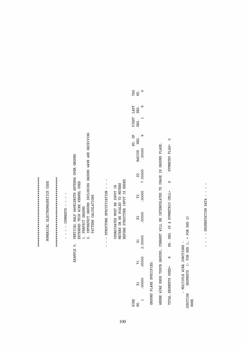
****
****
****
****
****
****
****
****
****
NUME
RICA
LEL
ECTR
OMAG
NETI
CSCO
DE
****
****
****
****
****
****
****
****
****
--
--
COMM
ENTS
--
--
EXAM
PLE
3.VE
RTIC
ALHA
LFWA
VELE
NGTH
ANTE
NNA
OVER
GROU
NDEX
TEND
EDTH
INWI
REKE
RNEL
USED
1.PE
RFEC
TGR
OUND
2.IM
PERF
ECT
GROU
NDIN
CLUD
ING
GROU
NDWA
VEAN
DRE
CEIV
ING
PATT
ERN
CALC
ULAT
IONS
--
-ST
RUCT
URE
SPEC
IFIC
ATIO
N-
--
COOR
DINA
TES
MUST
BEIN
PUT
INME
TERS
ORBE
SCAL
EDTO
METE
RSBE
FORE
STRU
CTUR
EIN
PUT
ISEN
DED
WIRE
NO.
OFFI
RST
LAST
TAG
NO.
X1Y1
Z1X2
Y2Z2
RADI
USSE
G.SE
G.SE
G.NO
.1
.000
00.0
0000
2.00
000
.000
00.0
0000
7.00
000
.300
009
19
0
GROU
NDPL
ANE
SPEC
IFIE
D.
WHER
EWI
REEN
DSTO
UCH
GROU
ND,
CURR
ENT
WILL
BEIN
TERP
OLAT
EDTO
IMAG
EIN
GROU
NDPL
ANE.
TOTA
LSE
GMEN
TSUS
ED=
9NO
.SE
G.IN
ASY
MMET
RIC
CELL
=9
SYMM
ETRY
FLAG
=0
-MU
LTIP
LEWI
REJU
NCTI
ONS
-JU
NCTI
ONSE
GMEN
TS(-
FOR
END
1,+
FOR
END
2)NO
NE
--
--
SEGM
ENTA
TION
DATA
--
--
100
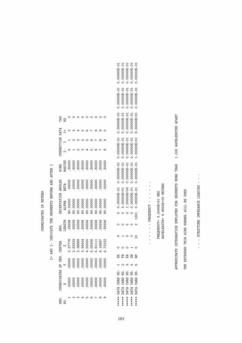
COOR
DINA
TES
INME
TERS
I+AN
DI-
INDI
CATE
THE
SEGM
ENTS
BEFO
REAN
DAF
TER
I
SEG.
COOR
DINA
TES
OFSE
G.CE
NTER
SEG.
ORIE
NTAT
ION
ANGL
ESWI
RECO
NNEC
TION
DATA
TAG
NO.
XY
ZLE
NGTH
ALPH
ABE
TARA
DIUS
I-I
I+NO
.1
.000
00.0
0000
2.27
778
.555
5690
.000
00.0
0000
.300
000
12
02
.000
00.0
0000
2.83
333
.555
5690
.000
00.0
0000
.300
001
23
03
.000
00.0
0000
3.38
889
.555
5690
.000
00.0
0000
.300
002
34
04
.000
00.0
0000
3.94
444
.555
5690
.000
00.0
0000
.300
003
45
05
.000
00.0
0000
4.50
000
.555
5690
.000
00.0
0000
.300
004
56
06
.000
00.0
0000
5.05
556
.555
5690
.000
00.0
0000
.300
005
67
07
.000
00.0
0000
5.61
111
.555
5690
.000
00.0
0000
.300
006
78
08
.000
00.0
0000
6.16
667
.555
5690
.000
00.0
0000
.300
007
89
09
.000
00.0
0000
6.72
222
.555
5690
.000
00.0
0000
.300
008
90
0
****
*DA
TACA
RDNO
.1
EK0
00
00.
0000
0E-0
10.
0000
0E-0
10.
0000
0E-0
10.
0000
0E-0
10.
0000
0E-0
10.
0000
0E-0
1**
***
DATA
CARD
NO.
2FR
01
00
3.00
000E
+01
0.00
000E
-01
0.00
000E
-01
0.00
000E
-01
0.00
000E
-01
0.00
000E
-01
****
*DA
TACA
RDNO
.3
EX0
05
01.
0000
0E+0
00.
0000
0E-0
10.
0000
0E-0
10.
0000
0E-0
10.
0000
0E-0
10.
0000
0E-0
1**
***
DATA
CARD
NO.
4GN
10
00
0.00
000E
-01
0.00
000E
-01
0.00
000E
-01
0.00
000E
-01
0.00
000E
-01
0.00
000E
-01
****
*DA
TACA
RDNO
.5
RP0
102
1301
0.00
000E
-01
0.00
000E
-01
1.00
000E
+01
9.00
000E
+01
0.00
000E
-01
0.00
000E
-01
--
--
--
FREQ
UENC
Y-
--
--
-
FREQ
UENC
Y=3.
0000
E+01
MHZ
WAVE
LENG
TH=
9.99
33E+
00ME
TERS
APPR
OXIM
ATE
INTE
GRAT
ION
EMPL
OYED
FOR
SEGM
ENTS
MORE
THAN
1.00
0WA
VELE
NGTH
SAP
ART
THE
EXTE
NDED
THIN
WIRE
KERN
ELWI
LLBE
USED
--
-ST
RUCT
URE
IMPE
DANC
ELO
ADIN
G-
--
101
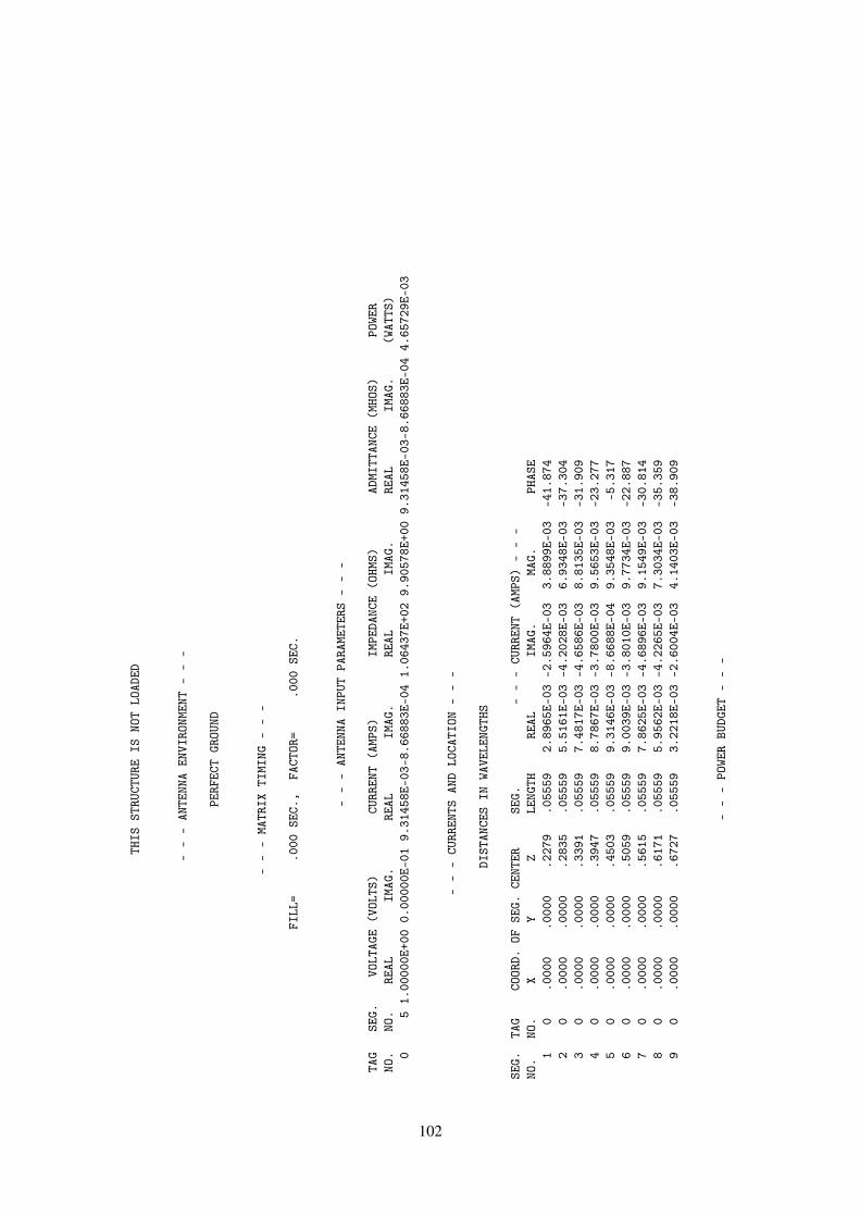
THIS
STRU
CTUR
EIS
NOT
LOAD
ED
--
-AN
TENN
AEN
VIRO
NMEN
T-
--
PERF
ECT
GROU
ND
--
-MA
TRIX
TIMI
NG-
--
FILL
=.0
00SE
C.,
FACT
OR=
.000
SEC.
--
-AN
TENN
AIN
PUT
PARA
METE
RS-
--
TAG
SEG.
VOLT
AGE
(VOL
TS)
CURR
ENT
(AMP
S)IM
PEDA
NCE
(OHM
S)AD
MITT
ANCE
(MHO
S)PO
WER
NO.
NO.
REAL
IMAG
.RE
ALIM
AG.
REAL
IMAG
.RE
ALIM
AG.
(WAT
TS)
05
1.00
000E
+00
0.00
000E
-01
9.31
458E
-03-
8.66
883E
-04
1.06
437E
+02
9.90
578E
+00
9.31
458E
-03-
8.66
883E
-04
4.65
729E
-03
--
-CU
RREN
TSAN
DLO
CATI
ON-
--
DIST
ANCE
SIN
WAVE
LENG
THS
SEG.
TAG
COOR
D.OF
SEG.
CENT
ERSE
G.-
--
CURR
ENT
(AMP
S)-
--
NO.
NO.
XY
ZLE
NGTH
REAL
IMAG
.MA
G.PH
ASE
10
.000
0.0
000
.227
9.0
5559
2.89
65E-
03-2
.596
4E-0
33.
8899
E-03
-41.
874
20
.000
0.0
000
.283
5.0
5559
5.51
61E-
03-4
.202
8E-0
36.
9348
E-03
-37.
304
30
.000
0.0
000
.339
1.0
5559
7.48
17E-
03-4
.658
6E-0
38.
8135
E-03
-31.
909
40
.000
0.0
000
.394
7.0
5559
8.78
67E-
03-3
.780
0E-0
39.
5653
E-03
-23.
277
50
.000
0.0
000
.450
3.0
5559
9.31
46E-
03-8
.668
8E-0
49.
3548
E-03
-5.3
176
0.0
000
.000
0.5
059
.055
599.
0039
E-03
-3.8
010E
-03
9.77
34E-
03-2
2.88
77
0.0
000
.000
0.5
615
.055
597.
8625
E-03
-4.6
896E
-03
9.15
49E-
03-3
0.81
48
0.0
000
.000
0.6
171
.055
595.
9562
E-03
-4.2
265E
-03
7.30
34E-
03-3
5.35
99
0.0
000
.000
0.6
727
.055
593.
2218
E-03
-2.6
004E
-03
4.14
03E-
03-3
8.90
9
--
-PO
WER
BUDG
ET-
--
102
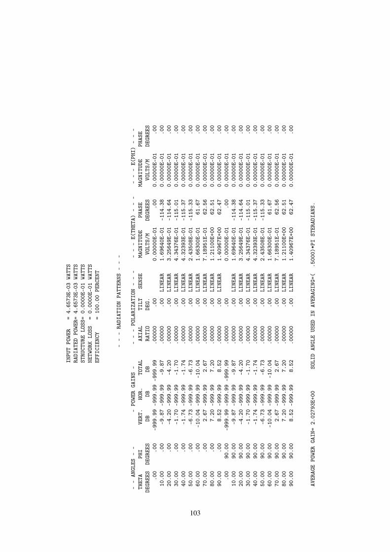
INPU
TPO
WER
=4.
6573
E-03
WATT
SRA
DIAT
EDPO
WER=
4.65
73E-
03WA
TTS
STRU
CTUR
ELO
SS=
0.00
00E-
01WA
TTS
NETW
ORK
LOSS
=0.
0000
E-01
WATT
SEF
FICI
ENCY
=10
0.00
PERC
ENT
--
-RA
DIAT
ION
PATT
ERNS
--
-
--
ANGL
ES-
--
POWE
RGA
INS
--
--
POLA
RIZA
TION
--
--
--
E(TH
ETA)
--
--
--
E(PH
I)-
--
THET
APH
IVE
RT.
HOR.
TOTA
LAX
IAL
TILT
SENS
EMA
GNIT
UDE
PHAS
EMA
GNIT
UDE
PHAS
EDE
GREE
SDE
GREE
SDB
DBDB
RATI
ODE
G.VO
LTS/
MDE
GREE
SVO
LTS/
MDE
GREE
S.0
0.0
0-9
99.9
9-9
99.9
9-9
99.9
9.0
0000
.00
0.00
000E
-01
.00
0.00
000E
-01
.00
10.0
0.0
0-9
.87
-999
.99
-9.8
7.0
0000
.00
LINE
AR1.
6964
0E-0
1-1
14.3
80.
0000
0E-0
1.0
020
.00
.00
-4.2
0-9
99.9
9-4
.20
.000
00.0
0LI
NEAR
3.25
649E
-01
-114
.64
0.00
000E
-01
.00
30.0
0.0
0-1
.70
-999
.99
-1.7
0.0
0000
.00
LINE
AR4.
3437
6E-0
1-1
15.0
10.
0000
0E-0
1.0
040
.00
.00
-1.7
4-9
99.9
9-1
.74
.000
00.0
0LI
NEAR
4.32
393E
-01
-115
.37
0.00
000E
-01
.00
50.0
0.0
0-6
.73
-999
.99
-6.7
3.0
0000
.00
LINE
AR2.
4350
8E-0
1-1
15.3
30.
0000
0E-0
1.0
060
.00
.00
-10.
04-9
99.9
9-1
0.04
.000
00.0
0LI
NEAR
1.66
300E
-01
61.6
70.
0000
0E-0
1.0
070
.00
.00
2.67
-999
.99
2.67
.000
00.0
0LI
NEAR
7.18
951E
-01
62.5
60.
0000
0E-0
1.0
080
.00
.00
7.20
-999
.99
7.20
.000
00.0
0LI
NEAR
1.21
100E
+00
62.5
10.
0000
0E-0
1.0
090
.00
.00
8.52
-999
.99
8.52
.000
00.0
0LI
NEAR
1.40
967E
+00
62.4
70.
0000
0E-0
1.0
0.0
090
.00
-999
.99
-999
.99
-999
.99
.000
00.0
00.
0000
0E-0
1.0
00.
0000
0E-0
1.0
010
.00
90.0
0-9
.87
-999
.99
-9.8
7.0
0000
.00
LINE
AR1.
6964
0E-0
1-1
14.3
80.
0000
0E-0
1.0
020
.00
90.0
0-4
.20
-999
.99
-4.2
0.0
0000
.00
LINE
AR3.
2564
9E-0
1-1
14.6
40.
0000
0E-0
1.0
030
.00
90.0
0-1
.70
-999
.99
-1.7
0.0
0000
.00
LINE
AR4.
3437
6E-0
1-1
15.0
10.
0000
0E-0
1.0
040
.00
90.0
0-1
.74
-999
.99
-1.7
4.0
0000
.00
LINE
AR4.
3239
3E-0
1-1
15.3
70.
0000
0E-0
1.0
050
.00
90.0
0-6
.73
-999
.99
-6.7
3.0
0000
.00
LINE
AR2.
4350
8E-0
1-1
15.3
30.
0000
0E-0
1.0
060
.00
90.0
0-1
0.04
-999
.99
-10.
04.0
0000
.00
LINE
AR1.
6630
0E-0
161
.67
0.00
000E
-01
.00
70.0
090
.00
2.67
-999
.99
2.67
.000
00.0
0LI
NEAR
7.18
951E
-01
62.5
60.
0000
0E-0
1.0
080
.00
90.0
07.
20-9
99.9
97.
20.0
0000
.00
LINE
AR1.
2110
0E+0
062
.51
0.00
000E
-01
.00
90.0
090
.00
8.52
-999
.99
8.52
.000
00.0
0LI
NEAR
1.40
967E
+00
62.4
70.
0000
0E-0
1.0
0
AVER
AGE
POWE
RGA
IN=
2.02
793E
+00
SOLI
DAN
GLE
USED
INAV
ERAG
ING=
(.5
000)
*PI
STER
ADIA
NS.
103
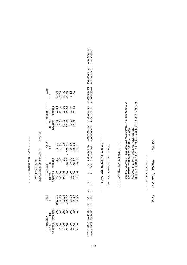
--
--
NORM
ALIZ
EDGA
IN-
--
-
VERT
ICAL
GAIN
NORM
ALIZ
ATIO
NFA
CTOR
=8.
52DB
--
ANGL
ES’
--
GAIN
--
ANGL
ES’
--
GAIN
--
ANGL
ES’
--
GAIN
THET
APH
IDB
THET
APH
IDB
THET
APH
IDB
DEGR
EES
DEGR
EES
DEGR
EES
DEGR
EES
DEGR
EES
DEGR
EES
.00
.00
-100
8.51
70.0
0.0
0-5
.85
40.0
090
.00
-10.
2610
.00
.00
-18.
3980
.00
.00
-1.3
250
.00
90.0
0-1
5.25
20.0
0.0
0-1
2.73
90.0
0.0
0.0
060
.00
90.0
0-1
8.56
30.0
0.0
0-1
0.23
.00
90.0
0-1
008.
5170
.00
90.0
0-5
.85
40.0
0.0
0-1
0.26
10.0
090
.00
-18.
3980
.00
90.0
0-1
.32
50.0
0.0
0-1
5.25
20.0
090
.00
-12.
7390
.00
90.0
0.0
060
.00
.00
-18.
5630
.00
90.0
0-1
0.23
****
*DA
TACA
RDNO
.6
GN0
00
06.
0000
0E+0
01.
0000
0E-0
30.
0000
0E-0
10.
0000
0E-0
10.
0000
0E-0
10.
0000
0E-0
1**
***
DATA
CARD
NO.
7RP
010
213
010.
0000
0E-0
10.
0000
0E-0
11.
0000
0E+0
19.
0000
0E+0
10.
0000
0E-0
10.
0000
0E-0
1
--
-ST
RUCT
URE
IMPE
DANC
ELO
ADIN
G-
--
THIS
STRU
CTUR
EIS
NOT
LOAD
ED
--
-AN
TENN
AEN
VIRO
NMEN
T-
--
FINI
TEGR
OUND
.RE
FLEC
TION
COEF
FICI
ENT
APPR
OXIM
ATIO
NRE
LATI
VEDI
ELEC
TRIC
CONS
T.=
6.00
0CO
NDUC
TIVI
TY=
1.00
0E-0
3MH
OS/M
ETER
COMP
LEX
DIEL
ECTR
ICCO
NSTA
NT=
6.00
000E
+00-
5.99
200E
-01
--
-MA
TRIX
TIMI
NG-
--
FILL
=.0
00SE
C.,
FACT
OR=
.000
SEC.
104

--
-AN
TENN
AIN
PUT
PARA
METE
RS-
--
TAG
SEG.
VOLT
AGE
(VOL
TS)
CURR
ENT
(AMP
S)IM
PEDA
NCE
(OHM
S)AD
MITT
ANCE
(MHO
S)PO
WER
NO.
NO.
REAL
IMAG
.RE
ALIM
AG.
REAL
IMAG
.RE
ALIM
AG.
(WAT
TS)
05
1.00
000E
+00
0.00
000E
-01
8.91
204E
-03-
8.82
840E
-04
1.11
117E
+02
1.10
075E
+01
8.91
204E
-03-
8.82
840E
-04
4.45
602E
-03
--
-CU
RREN
TSAN
DLO
CATI
ON-
--
DIST
ANCE
SIN
WAVE
LENG
THS
SEG.
TAG
COOR
D.OF
SEG.
CENT
ERSE
G.-
--
CURR
ENT
(AMP
S)-
--
NO.
NO.
XY
ZLE
NGTH
REAL
IMAG
.MA
G.PH
ASE
10
.000
0.0
000
.227
9.0
5559
2.87
69E-
03-2
.572
8E-0
33.
8595
E-03
-41.
807
20
.000
0.0
000
.283
5.0
5559
5.41
54E-
03-4
.189
3E-0
36.
8467
E-03
-37.
725
30
.000
0.0
000
.339
1.0
5559
7.27
28E-
03-4
.662
7E-0
38.
6391
E-03
-32.
665
40
.000
0.0
000
.394
7.0
5559
8.46
96E-
03-3
.795
2E-0
39.
2810
E-03
-24.
137
50
.000
0.0
000
.450
3.0
5559
8.91
20E-
03-8
.828
4E-0
48.
9557
E-03
-5.6
576
0.0
000
.000
0.5
059
.055
598.
5577
E-03
-3.8
085E
-03
9.36
69E-
03-2
3.99
17
0.0
000
.000
0.5
615
.055
597.
4274
E-03
-4.6
836E
-03
8.78
07E-
03-3
2.23
58
0.0
000
.000
0.6
171
.055
595.
5943
E-03
-4.2
085E
-03
7.00
05E-
03-3
6.95
49
0.0
000
.000
0.6
727
.055
593.
0094
E-03
-2.5
815E
-03
3.96
49E-
03-4
0.62
3
--
-PO
WER
BUDG
ET-
--
INPU
TPO
WER
=4.
4560
E-03
WATT
SRA
DIAT
EDPO
WER=
4.45
60E-
03WA
TTS
STRU
CTUR
ELO
SS=
0.00
00E-
01WA
TTS
NETW
ORK
LOSS
=0.
0000
E-01
WATT
SEF
FICI
ENCY
=10
0.00
PERC
ENT
--
-RA
DIAT
ION
PATT
ERNS
--
-
--
ANGL
ES-
--
POWE
RGA
INS
--
--
POLA
RIZA
TION
--
--
--
E(TH
ETA)
--
--
--
E(PH
I)-
--
THET
APH
IVE
RT.
HOR.
TOTA
LAX
IAL
TILT
SENS
EMA
GNIT
UDE
PHAS
EMA
GNIT
UDE
PHAS
E
105

DEGR
EES
DEGR
EES
DBDB
DBRA
TIO
DEG.
VOLT
S/M
DEGR
EES
VOLT
S/M
DEGR
EES
.00
.00
-999
.99
-999
.99
-999
.99
.000
00.0
00.
0000
0E-0
1.0
00.
0000
0E-0
1.0
010
.00
.00
-12.
87-9
99.9
9-1
2.87
.000
00.0
0LI
NEAR
1.17
471E
-01
-124
.70
0.00
000E
-01
.00
20.0
0.0
0-7
.18
-999
.99
-7.1
8.0
0000
.00
LINE
AR2.
2614
8E-0
1-1
28.9
10.
0000
0E-0
1.0
030
.00
.00
-4.4
7-9
99.9
9-4
.47
.000
00.0
0LI
NEAR
3.08
872E
-01
-137
.31
0.00
000E
-01
.00
40.0
0.0
0-3
.45
-999
.99
-3.4
5.0
0000
.00
LINE
AR3.
4727
1E-0
1-1
53.4
10.
0000
0E-0
1.0
050
.00
.00
-2.9
4-9
99.9
9-2
.94
.000
00.0
0LI
NEAR
3.68
436E
-01
177.
070.
0000
0E-0
1.0
060
.00
.00
-.79
-999
.99
-.79
.000
00.0
0LI
NEAR
4.71
934E
-01
142.
060.
0000
0E-0
1.0
070
.00
.00
1.54
-999
.99
1.54
.000
00.0
0LI
NEAR
6.16
990E
-01
120.
370.
0000
0E-0
1.0
080
.00
.00
.64
-999
.99
.64
.000
00.0
0LI
NEAR
5.56
472E
-01
110.
410.
0000
0E-0
1.0
090
.00
.00
-128
.37
-999
.99
-128
.37
.000
00.0
0LI
NEAR
1.97
295E
-07
-45.
000.
0000
0E-0
1.0
0.0
090
.00
-999
.99
-999
.99
-999
.99
.000
00.0
00.
0000
0E-0
1.0
00.
0000
0E-0
1.0
010
.00
90.0
0-1
2.87
-999
.99
-12.
87.0
0000
.00
LINE
AR1.
1747
1E-0
1-1
24.7
00.
0000
0E-0
1.0
020
.00
90.0
0-7
.18
-999
.99
-7.1
8.0
0000
.00
LINE
AR2.
2614
8E-0
1-1
28.9
10.
0000
0E-0
1.0
030
.00
90.0
0-4
.47
-999
.99
-4.4
7.0
0000
.00
LINE
AR3.
0887
2E-0
1-1
37.3
10.
0000
0E-0
1.0
040
.00
90.0
0-3
.45
-999
.99
-3.4
5.0
0000
.00
LINE
AR3.
4727
1E-0
1-1
53.4
10.
0000
0E-0
1.0
050
.00
90.0
0-2
.94
-999
.99
-2.9
4.0
0000
.00
LINE
AR3.
6843
6E-0
117
7.07
0.00
000E
-01
.00
60.0
090
.00
-.79
-999
.99
-.79
.000
00.0
0LI
NEAR
4.71
934E
-01
142.
060.
0000
0E-0
1.0
070
.00
90.0
01.
54-9
99.9
91.
54.0
0000
.00
LINE
AR6.
1699
0E-0
112
0.37
0.00
000E
-01
.00
80.0
090
.00
.64
-999
.99
.64
.000
00.0
0LI
NEAR
5.56
472E
-01
110.
410.
0000
0E-0
1.0
090
.00
90.0
0-1
28.3
7-9
99.9
9-1
28.3
7.0
0000
.00
LINE
AR1.
9729
5E-0
7-4
5.00
0.00
000E
-01
.00
AVER
AGE
POWE
RGA
IN=
7.20
699E
-01
SOLI
DAN
GLE
USED
INAV
ERAG
ING=
(.5
000)
*PI
STER
ADIA
NS.
--
--
NORM
ALIZ
EDGA
IN-
--
-
VERT
ICAL
GAIN
NORM
ALIZ
ATIO
NFA
CTOR
=1.
54DB
--
ANGL
ES’
--
GAIN
--
ANGL
ES’
--
GAIN
--
ANGL
ES’
--
GAIN
THET
APH
IDB
THET
APH
IDB
THET
APH
IDB
DEGR
EES
DEGR
EES
DEGR
EES
DEGR
EES
DEGR
EES
DEGR
EES
.00
.00
-100
1.53
70.0
0.0
0.0
040
.00
90.0
0-4
.99
10.0
0.0
0-1
4.41
80.0
0.0
0-.
9050
.00
90.0
0-4
.48
20.0
0.0
0-8
.72
90.0
0.0
0-1
29.9
060
.00
90.0
0-2
.33
30.0
0.0
0-6
.01
.00
90.0
0-1
001.
5370
.00
90.0
0.0
0
106
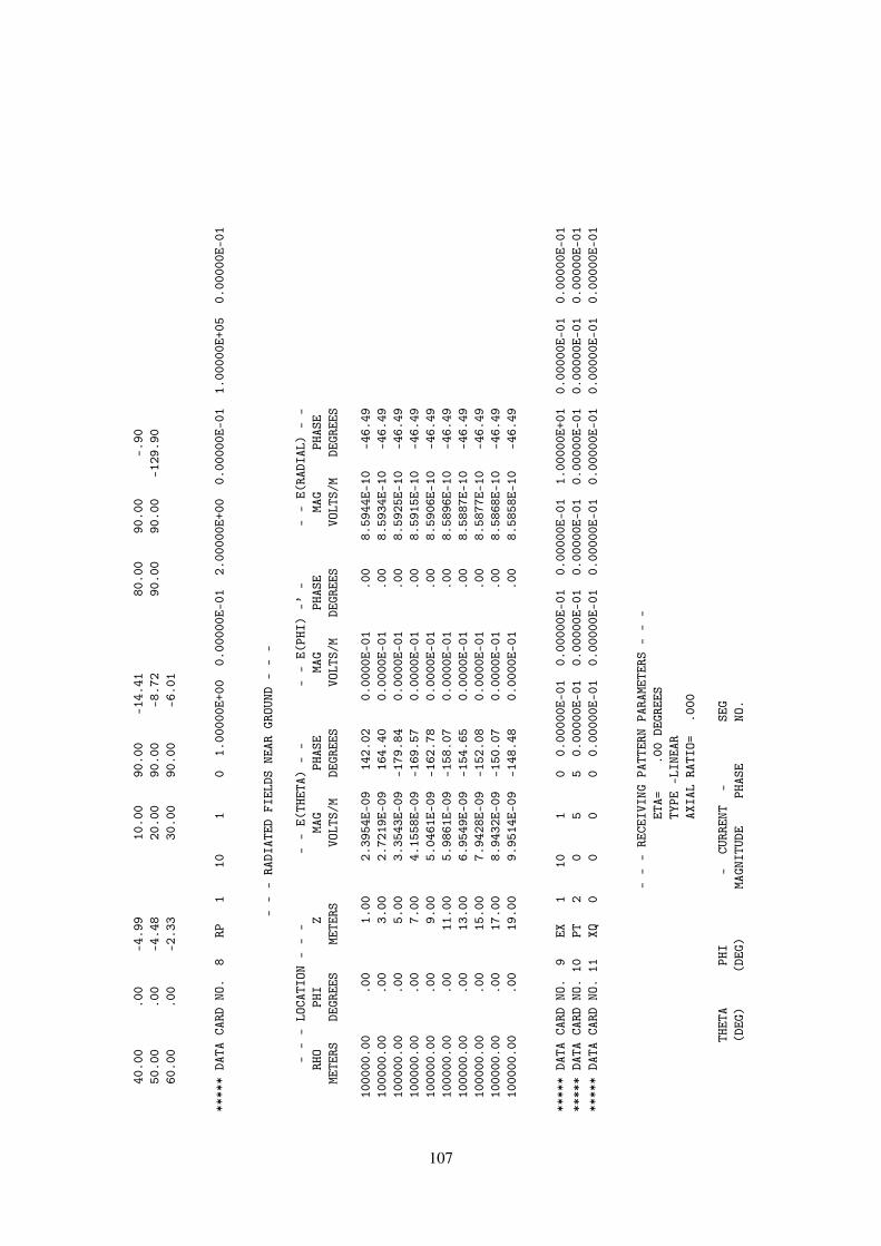
40.0
0.0
0-4
.99
10.0
090
.00
-14.
4180
.00
90.0
0-.
9050
.00
.00
-4.4
820
.00
90.0
0-8
.72
90.0
090
.00
-129
.90
60.0
0.0
0-2
.33
30.0
090
.00
-6.0
1
****
*DA
TACA
RDNO
.8
RP1
101
01.
0000
0E+0
00.
0000
0E-0
12.
0000
0E+0
00.
0000
0E-0
11.
0000
0E+0
50.
0000
0E-0
1
--
-RA
DIAT
EDFI
ELDS
NEAR
GROU
ND-
--
--
-LO
CATI
ON-
--
--
E(TH
ETA)
--
--
E(PH
I)-’
--
-E(
RADI
AL)
--
RHO
PHI
ZMA
GPH
ASE
MAG
PHAS
EMA
GPH
ASE
METE
RSDE
GREE
SME
TERS
VOLT
S/M
DEGR
EES
VOLT
S/M
DEGR
EES
VOLT
S/M
DEGR
EES
1000
00.0
0.0
01.
002.
3954
E-09
142.
020.
0000
E-01
.00
8.59
44E-
10-4
6.49
1000
00.0
0.0
03.
002.
7219
E-09
164.
400.
0000
E-01
.00
8.59
34E-
10-4
6.49
1000
00.0
0.0
05.
003.
3543
E-09
-179
.84
0.00
00E-
01.0
08.
5925
E-10
-46.
4910
0000
.00
.00
7.00
4.15
58E-
09-1
69.5
70.
0000
E-01
.00
8.59
15E-
10-4
6.49
1000
00.0
0.0
09.
005.
0461
E-09
-162
.78
0.00
00E-
01.0
08.
5906
E-10
-46.
4910
0000
.00
.00
11.0
05.
9861
E-09
-158
.07
0.00
00E-
01.0
08.
5896
E-10
-46.
4910
0000
.00
.00
13.0
06.
9549
E-09
-154
.65
0.00
00E-
01.0
08.
5887
E-10
-46.
4910
0000
.00
.00
15.0
07.
9428
E-09
-152
.08
0.00
00E-
01.0
08.
5877
E-10
-46.
4910
0000
.00
.00
17.0
08.
9432
E-09
-150
.07
0.00
00E-
01.0
08.
5868
E-10
-46.
4910
0000
.00
.00
19.0
09.
9514
E-09
-148
.48
0.00
00E-
01.0
08.
5858
E-10
-46.
49
****
*DA
TACA
RDNO
.9
EX1
101
00.
0000
0E-0
10.
0000
0E-0
10.
0000
0E-0
11.
0000
0E+0
10.
0000
0E-0
10.
0000
0E-0
1**
***
DATA
CARD
NO.
10PT
20
55
0.00
000E
-01
0.00
000E
-01
0.00
000E
-01
0.00
000E
-01
0.00
000E
-01
0.00
000E
-01
****
*DA
TACA
RDNO
.11
XQ0
00
00.
0000
0E-0
10.
0000
0E-0
10.
0000
0E-0
10.
0000
0E-0
10.
0000
0E-0
10.
0000
0E-0
1
--
-RE
CEIV
ING
PATT
ERN
PARA
METE
RS-
--
ETA=
.00
DEGR
EES
TYPE
-LIN
EAR
AXIA
LRA
TIO=
.000
THET
APH
I-
CURR
ENT
-SE
G(D
EG)
(DEG
)MA
GNIT
UDE
PHAS
ENO
.
107

.00
.00
0.00
00E-
01.0
05
10.0
0.0
06.
2308
E-03
-34.
695
20.0
0.0
01.
1997
E-02
-38.
905
30.0
0.0
01.
6389
E-02
-47.
305
40.0
0.0
01.
8430
E-02
-63.
415
50.0
0.0
01.
9558
E-02
-92.
935
60.0
0.0
02.
5058
E-02
-127
.94
570
.00
.00
3.27
66E-
02-1
49.6
35
80.0
0.0
02.
9555
E-02
-159
.59
590
.00
.00
9.79
19E-
0935
.39
5
--
-NO
RMAL
IZED
RECE
IVIN
GPA
TTER
N-
--
NORM
ALIZ
ATIO
NFA
CTOR
=3.
2766
E-02
ETA=
.00
DEGR
EES
TYPE
-LIN
EAR
AXIA
LRA
TIO=
.000
SEGM
ENT
NO.=
5
THET
APH
I-
PATT
ERN
-(D
EG)
(DEG
)DB
MAGN
ITUD
E
.00
.00
-999
.99
0.00
00E-
0110
.00
.00
-14.
421.
9016
E-01
20.0
0.0
0-8
.73
3.66
14E-
0130
.00
.00
-6.0
25.
0017
E-01
40.0
0.0
0-5
.00
5.62
48E-
0150
.00
.00
-4.4
85.
9691
E-01
60.0
0.0
0-2
.33
7.64
76E-
0170
.00
.00
.00
1.00
00E+
0080
.00
.00
-.90
9.02
01E-
0190
.00
.00
-130
.49
2.98
84E-
07
****
*DA
TACA
RDNO
.12
EN0
00
00.
0000
0E-0
10.
0000
0E-0
10.
0000
0E-0
10.
0000
0E-0
10.
0000
0E-0
10.
0000
0E-0
1
RUN
TIME
=.0
00
108

4.2.4 Antenna on a Box Over a Perfect Ground.
Includes both patches and wires. Although the structure is over a perfect ground, the averagepower gain is 1.8. This indicates that the input impedance is inaccurate, probably due to the crudepatch model used for the box. Since there is no ohmic loss, a more accurate input resistance canbe obtained as :
Radiated Power = (1/2)× (avg. gain)× (computed input power)= 1.016 (10−3)W
Radiation resistance = 2× (radiated power) / | Isource|2= 162.6 ohms
Since the input power used in computing the gains in the radiated pattern table is to large by 0.46dB, the gains can be corrected by adding this factor.
Input Card Deck :
CEEXAMPLE 4. T ANTENNA ON A BOX OVER A PERFECT GROUNDSP 0 0 .1 .05 .05 0. 0. .01SP 0 0 .05 .1 .05 0. 90. .01GX 0 110SP 0 0 0. 0. .1 90. 0. .04GW 1 4 0. 0. .1 0. 0. .3 .001GW 2 2 0. 0. .3 .15 0. .3 .001GW 3 2 0. 0. .3 -.15 0. .3 .001GE 1GN 1EX 0 1 1 0 1.RP 0 10 4 1001 0. 0. 10. 30.EN
Line-Printer Output :
109
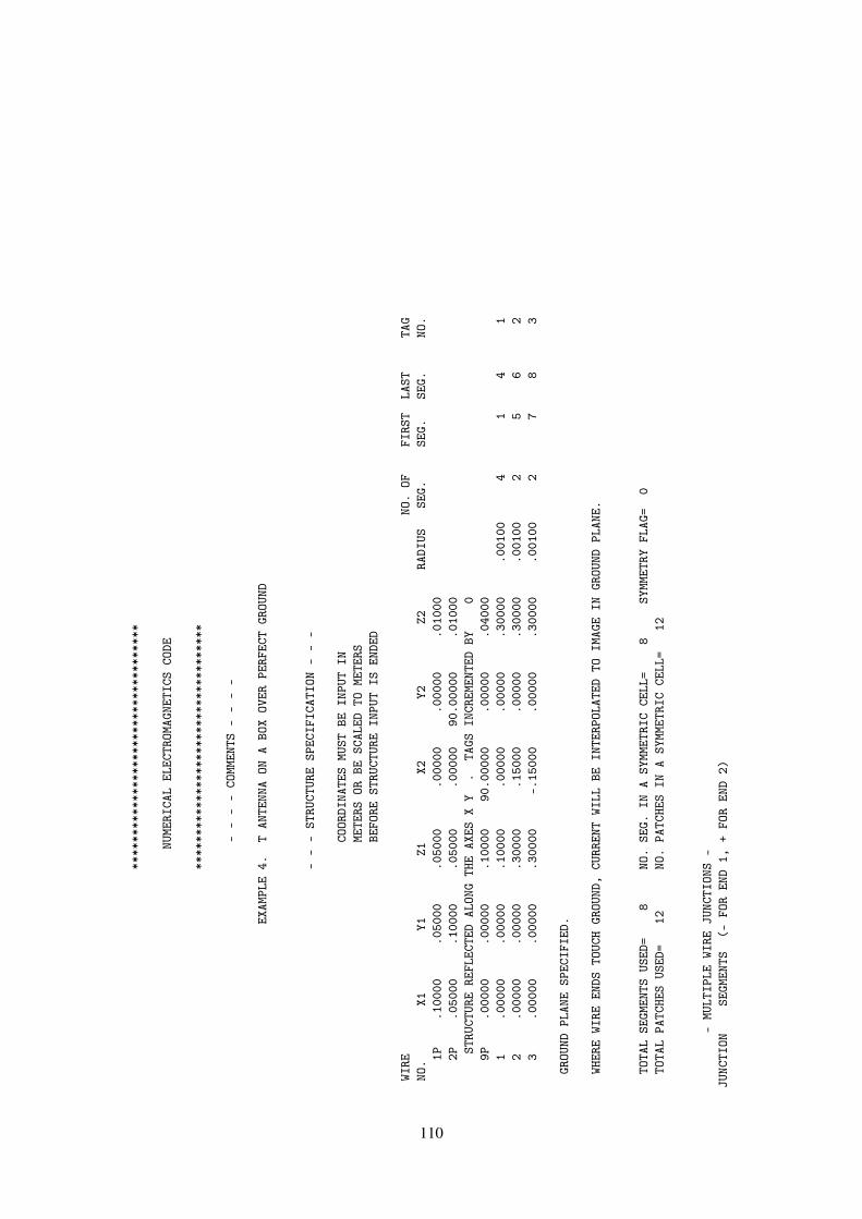
****
****
****
****
****
****
****
****
****
NUME
RICA
LEL
ECTR
OMAG
NETI
CSCO
DE
****
****
****
****
****
****
****
****
****
--
--
COMM
ENTS
--
--
EXAM
PLE
4.T
ANTE
NNA
ONA
BOX
OVER
PERF
ECT
GROU
ND
--
-ST
RUCT
URE
SPEC
IFIC
ATIO
N-
--
COOR
DINA
TES
MUST
BEIN
PUT
INME
TERS
ORBE
SCAL
EDTO
METE
RSBE
FORE
STRU
CTUR
EIN
PUT
ISEN
DED
WIRE
NO.
OFFI
RST
LAST
TAG
NO.
X1Y1
Z1X2
Y2Z2
RADI
USSE
G.SE
G.SE
G.NO
.1P
.100
00.0
5000
.050
00.0
0000
.000
00.0
1000
2P.0
5000
.100
00.0
5000
.000
0090
.000
00.0
1000
STRU
CTUR
ERE
FLEC
TED
ALON
GTH
EAX
ESX
Y.
TAGS
INCR
EMEN
TED
BY0
9P.0
0000
.000
00.1
0000
90.0
0000
.000
00.0
4000
1.0
0000
.000
00.1
0000
.000
00.0
0000
.300
00.0
0100
41
41
2.0
0000
.000
00.3
0000
.150
00.0
0000
.300
00.0
0100
25
62
3.0
0000
.000
00.3
0000
-.15
000
.000
00.3
0000
.001
002
78
3
GROU
NDPL
ANE
SPEC
IFIE
D.
WHER
EWI
REEN
DSTO
UCH
GROU
ND,
CURR
ENT
WILL
BEIN
TERP
OLAT
EDTO
IMAG
EIN
GROU
NDPL
ANE.
TOTA
LSE
GMEN
TSUS
ED=
8NO
.SE
G.IN
ASY
MMET
RIC
CELL
=8
SYMM
ETRY
FLAG
=0
TOTA
LPA
TCHE
SUS
ED=
12NO
.PA
TCHE
SIN
ASY
MMET
RIC
CELL
=12
-MU
LTIP
LEWI
REJU
NCTI
ONS
-JU
NCTI
ONSE
GMEN
TS(-
FOR
END
1,+
FOR
END
2)
110

14
-5-7
--
--
SEGM
ENTA
TION
DATA
--
--
COOR
DINA
TES
INME
TERS
I+AN
DI-
INDI
CATE
THE
SEGM
ENTS
BEFO
REAN
DAF
TER
I
SEG.
COOR
DINA
TES
OFSE
G.CE
NTER
SEG.
ORIE
NTAT
ION
ANGL
ESWI
RECO
NNEC
TION
DATA
TAG
NO.
XY
ZLE
NGTH
ALPH
ABE
TARA
DIUS
I-I
I+NO
.1
.000
00.0
0000
.125
00.0
5000
90.0
0000
.000
00.0
0100
1000
91
21
2.0
0000
.000
00.1
7500
.050
0090
.000
00.0
0000
.001
001
23
13
.000
00.0
0000
.225
00.0
5000
90.0
0000
.000
00.0
0100
23
41
4.0
0000
.000
00.2
7500
.050
0090
.000
00.0
0000
.001
003
45
15
.037
50.0
0000
.300
00.0
7500
.000
00.0
0000
.001
00-7
56
26
.112
50.0
0000
.300
00.0
7500
.000
00.0
0000
.001
005
60
27
-.03
750
.000
00.3
0000
.075
00.0
0000
180.
0000
0.0
0100
47
83
8-.
1125
0.0
0000
.300
00.0
7500
.000
0018
0.00
000
.001
007
80
3
--
-SU
RFAC
EPA
TCH
DATA
--
-
COOR
DINA
TES
INME
TERS
PATC
HCO
ORD.
OFPA
TCH
CENT
ERUN
ITNO
RMAL
VECT
ORPA
TCH
COMP
ONEN
TSOF
UNIT
TANG
ENT
V’EC
TORS
NO.
XY
ZX
YZ
AREA
X1Y1
Z1X2
Y2Z2
1.1
0000
.050
00.0
5000
1.00
00.0
000
-.00
00.0
1000
.000
01.
0000
.000
0.0
000
-.00
001.
0000
2.0
5000
.100
00.0
5000
0.00
001.
0000
.000
0.0
1000
-1.0
000
0.00
00.0
000
.000
0.0
000
1.00
003
.100
00-.
0500
0.0
5000
1.00
00-.
0000
-.00
00.0
1000
.000
0-1
.000
0.0
000
.000
0.0
000
1.00
004
.050
00-.
1000
0.0
5000
0.00
00-1
.000
0-.
0000
.010
00-1
.000
00.
0000
.000
0.0
000
-.00
001.
0000
5-.
1000
0.0
5000
.050
00-1
.000
0-.
0000
-.00
00.0
1000
-.00
001.
0000
.000
0-.
0000
-.00
001.
0000
6-.
0500
0.1
0000
.050
000.
0000
1.00
00-.
0000
.010
001.
0000
0.00
00.0
000
-.00
00.0
000
1.00
007
-.10
000
-.05
000
.050
00-1
.000
0.0
000
-.00
00.0
1000
-.00
00-1
.000
0.0
000
-.00
00.0
000
1.00
008
-.05
000
-.10
000
.050
000.
0000
-1.0
000
.000
0.0
1000
1.00
000.
0000
.000
0-.
0000
-.00
001.
0000
9.0
5000
.050
00.1
0000
-.00
00.0
000
1.00
00.0
1000
1.00
00.0
000
.000
0.0
000
1.00
00-.
0000
10-.
0500
0.0
5000
.100
00-.
0000
.000
01.
0000
.010
001.
0000
.000
0.0
000
.000
01.
0000
-.00
0011
-.05
000
-.05
000
.100
00-.
0000
.000
01.
0000
.010
001.
0000
.000
0.0
000
.000
01.
0000
-.00
00
111
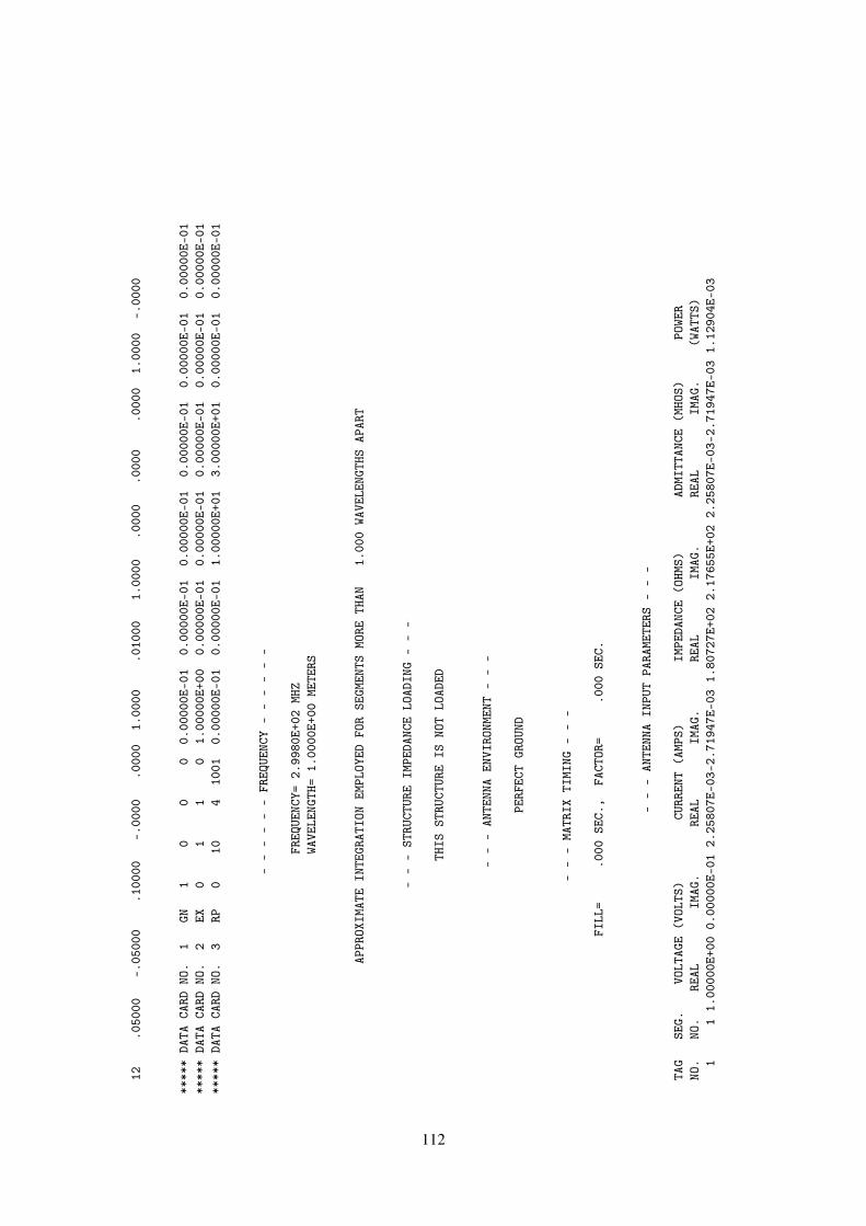
12.0
5000
-.05
000
.100
00-.
0000
.000
01.
0000
.010
001.
0000
.000
0.0
000
.000
01.
0000
-.00
00
****
*DA
TACA
RDNO
.1
GN1
00
00.
0000
0E-0
10.
0000
0E-0
10.
0000
0E-0
10.
0000
0E-0
10.
0000
0E-0
10.
0000
0E-0
1**
***
DATA
CARD
NO.
2EX
01
10
1.00
000E
+00
0.00
000E
-01
0.00
000E
-01
0.00
000E
-01
0.00
000E
-01
0.00
000E
-01
****
*DA
TACA
RDNO
.3
RP0
104
1001
0.00
000E
-01
0.00
000E
-01
1.00
000E
+01
3.00
000E
+01
0.00
000E
-01
0.00
000E
-01
--
--
--
FREQ
UENC
Y-
--
--
-
FREQ
UENC
Y=2.
9980
E+02
MHZ
WAVE
LENG
TH=
1.00
00E+
00ME
TERS
APPR
OXIM
ATE
INTE
GRAT
ION
EMPL
OYED
FOR
SEGM
ENTS
MORE
THAN
1.00
0WA
VELE
NGTH
SAP
ART
--
-ST
RUCT
URE
IMPE
DANC
ELO
ADIN
G-
--
THIS
STRU
CTUR
EIS
NOT
LOAD
ED
--
-AN
TENN
AEN
VIRO
NMEN
T-
--
PERF
ECT
GROU
ND
--
-MA
TRIX
TIMI
NG-
--
FILL
=.0
00SE
C.,
FACT
OR=
.000
SEC.
--
-AN
TENN
AIN
PUT
PARA
METE
RS-
--
TAG
SEG.
VOLT
AGE
(VOL
TS)
CURR
ENT
(AMP
S)IM
PEDA
NCE
(OHM
S)AD
MITT
ANCE
(MHO
S)PO
WER
NO.
NO.
REAL
IMAG
.RE
ALIM
AG.
REAL
IMAG
.RE
ALIM
AG.
(WAT
TS)
11
1.00
000E
+00
0.00
000E
-01
2.25
807E
-03-
2.71
947E
-03
1.80
727E
+02
2.17
655E
+02
2.25
807E
-03-
2.71
947E
-03
1.12
904E
-03
112
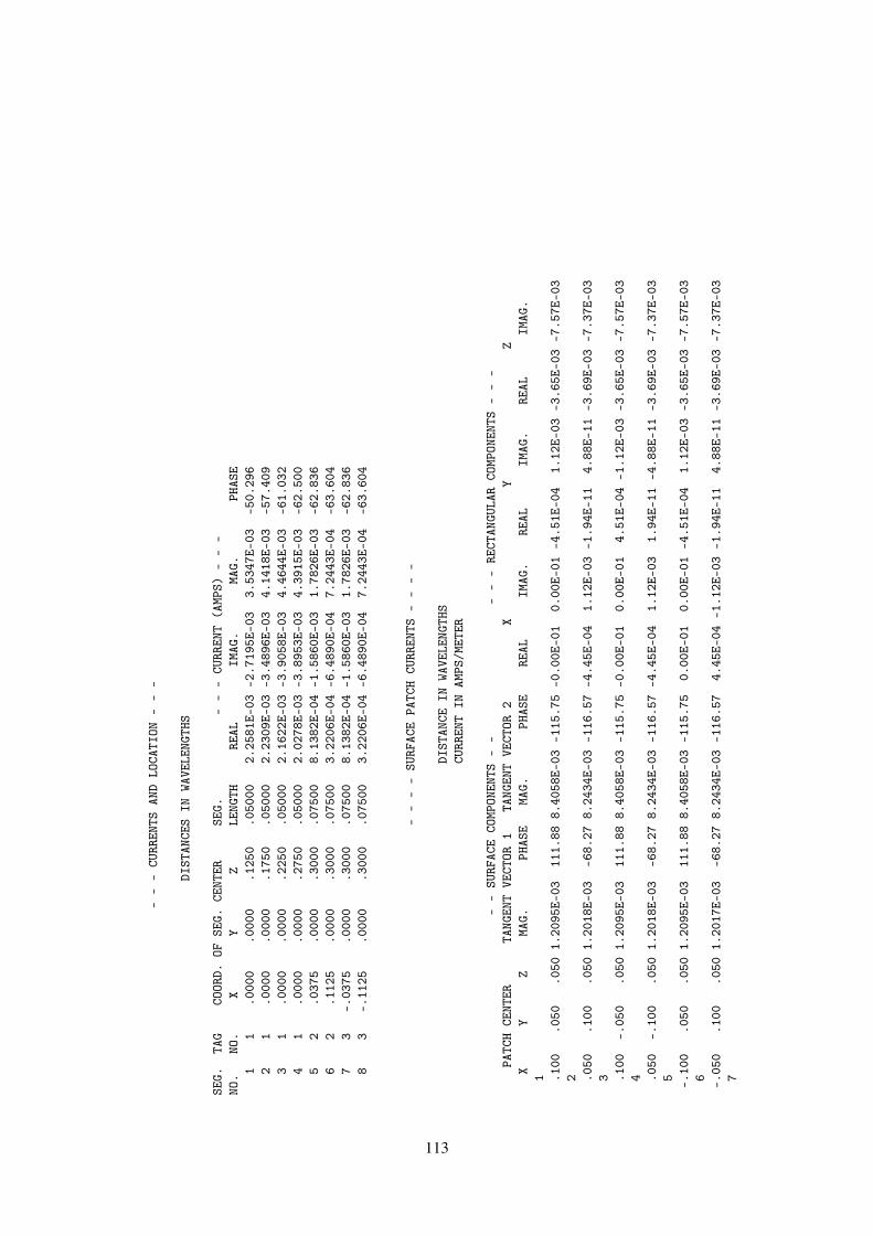
--
-CU
RREN
TSAN
DLO
CATI
ON-
--
DIST
ANCE
SIN
WAVE
LENG
THS
SEG.
TAG
COOR
D.OF
SEG.
CENT
ERSE
G.-
--
CURR
ENT
(AMP
S)-
--
NO.
NO.
XY
ZLE
NGTH
REAL
IMAG
.MA
G.PH
ASE
11
.000
0.0
000
.125
0.0
5000
2.25
81E-
03-2
.719
5E-0
33.
5347
E-03
-50.
296
21
.000
0.0
000
.175
0.0
5000
2.23
09E-
03-3
.489
6E-0
34.
1418
E-03
-57.
409
31
.000
0.0
000
.225
0.0
5000
2.16
22E-
03-3
.905
8E-0
34.
4644
E-03
-61.
032
41
.000
0.0
000
.275
0.0
5000
2.02
78E-
03-3
.895
3E-0
34.
3915
E-03
-62.
500
52
.037
5.0
000
.300
0.0
7500
8.13
82E-
04-1
.586
0E-0
31.
7826
E-03
-62.
836
62
.112
5.0
000
.300
0.0
7500
3.22
06E-
04-6
.489
0E-0
47.
2443
E-04
-63.
604
73
-.03
75.0
000
.300
0.0
7500
8.13
82E-
04-1
.586
0E-0
31.
7826
E-03
-62.
836
83
-.11
25.0
000
.300
0.0
7500
3.22
06E-
04-6
.489
0E-0
47.
2443
E-04
-63.
604
--
--
SURF
ACE
PATC
HCU
RREN
TS-
--
-
DIST
ANCE
INWA
VELE
NGTH
SCU
RREN
TIN
AMPS
/MET
ER
--
SURF
ACE
COMP
ONEN
TS-
--
--
RECT
ANGU
LAR
COMP
ONEN
TS-
--
PATC
HCE
NTER
TANG
ENT
VECT
OR1
TANG
ENT
VECT
OR2
XY
ZX
YZ
MAG.
PHAS
EMA
G.PH
ASE
REAL
IMAG
.RE
ALIM
AG.
REAL
IMAG
.1 .1
00.0
50.0
501.
2095
E-03
111.
888.
4058
E-03
-115
.75
-0.0
0E-0
10.
00E-
01-4
.51E
-04
1.12
E-03
-3.6
5E-0
3-7
.57E
-03
2 .050
.100
.050
1.20
18E-
03-6
8.27
8.24
34E-
03-1
16.5
7-4
.45E
-04
1.12
E-03
-1.9
4E-1
14.
88E-
11-3
.69E
-03
-7.3
7E-0
33 .1
00-.
050
.050
1.20
95E-
0311
1.88
8.40
58E-
03-1
15.7
5-0
.00E
-01
0.00
E-01
4.51
E-04
-1.1
2E-0
3-3
.65E
-03
-7.5
7E-0
34 .0
50-.
100
.050
1.20
18E-
03-6
8.27
8.24
34E-
03-1
16.5
7-4
.45E
-04
1.12
E-03
1.94
E-11
-4.8
8E-1
1-3
.69E
-03
-7.3
7E-0
35 -.10
0.0
50.0
501.
2095
E-03
111.
888.
4058
E-03
-115
.75
0.00
E-01
0.00
E-01
-4.5
1E-0
41.
12E-
03-3
.65E
-03
-7.5
7E-0
36 -.05
0.1
00.0
501.
2017
E-03
-68.
278.
2434
E-03
-116
.57
4.45
E-04
-1.1
2E-0
3-1
.94E
-11
4.88
E-11
-3.6
9E-0
3-7
.37E
-03
7
113
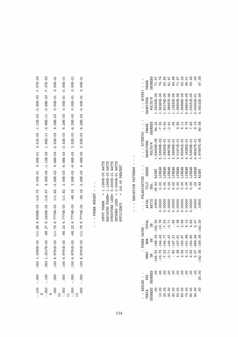
-.10
0-.
050
.050
1.20
95E-
0311
1.88
8.40
58E-
03-1
15.7
50.
00E-
010.
00E-
014.
51E-
04-1
.12E
-03
-3.6
5E-0
3-7
.57E
-03
8 -.05
0-.
100
.050
1.20
17E-
03-6
8.27
8.24
34E-
03-1
16.5
74.
45E-
04-1
.12E
-03
1.94
E-11
-4.8
8E-1
1-3
.69E
-03
-7.3
7E-0
39 .0
50.0
50.1
006.
9791
E-03
111.
786.
7774
E-03
111.
82-2
.59E
-03
6.48
E-03
-2.5
2E-0
36.
29E-
030.
00E-
010.
00E-
0110 -.
050
.050
.100
6.97
91E-
03-6
8.22
6.77
74E-
0311
1.82
2.59
E-03
-6.4
8E-0
3-2
.52E
-03
6.29
E-03
0.00
E-01
-0.0
0E-0
111 -.
050
-.05
0.1
006.
9791
E-03
-68.
226.
7774
E-03
-68.
182.
59E-
03-6
.48E
-03
2.52
E-03
-6.2
9E-0
30.
00E-
010.
00E-
0112 .0
50-.
050
.100
6.97
91E-
0311
1.78
6.77
74E-
03-6
8.18
-2.5
9E-0
36.
48E-
032.
52E-
03-6
.29E
-03
-0.0
0E-0
10.
00E-
01
--
-PO
WER
BUDG
ET-
--
INPU
TPO
WER
=1.
1290
E-03
WATT
SRA
DIAT
EDPO
WER=
1.12
90E-
03WA
TTS
STRU
CTUR
ELO
SS=
0.00
00E-
01WA
TTS
NETW
ORK
LOSS
=0.
0000
E-01
WATT
SEF
FICI
ENCY
=10
0.00
PERC
ENT
--
-RA
DIAT
ION
PATT
ERNS
--
-
--
ANGL
ES-
--
POWE
RGA
INS
--
--
POLA
RIZA
TION
--
--
--
E(TH
ETA)
--
--
--
E(PH
I)-
--
THET
APH
IVE
RT.
HOR.
TOTA
LAX
IAL
TILT
SENS
EMA
GNIT
UDE
PHAS
EMA
GNIT
UDE
PHAS
EDE
GREE
SDE
GREE
SDB
DBDB
RATI
ODE
G.VO
LTS/
MDE
GREE
SVO
LTS/
MDE
GREE
S.0
0.0
0-1
44.5
2-1
46.0
3-1
42.2
0.1
0900
39.9
3RI
GHT
1.54
659E
-08
84.2
01.
3002
0E-0
871
.57
10.0
0.0
0-1
3.76
-144
.43
-13.
760.
0000
00.
00LI
NEAR
5.33
569E
-02
-7.5
51.
5626
5E-0
874
.74
20.0
0.0
0-7
.53
-144
.77
-7.5
30.
0000
00.
00LI
NEAR
1.09
305E
-01
-5.6
21.
5017
4E-0
862
.85
30.0
0.0
0-3
.71
-145
.47
-3.7
10.
0000
00.
00LI
NEAR
1.69
676E
-01
-2.9
11.
3858
7E-0
881
.47
40.0
0.0
0-.
90-1
47.2
1-.
900.
0000
00.
00LI
NEAR
2.34
569E
-01
.05
1.13
432E
-08
64.9
850
.00
.00
1.28
-147
.61
1.28
0.00
000
0.00
LINE
AR3.
0147
1E-0
12.
821.
0835
0E-0
871
.57
60.0
0.0
02.
94-1
50.9
72.
940.
0000
00.
00LI
NEAR
3.65
091E
-01
5.11
7.35
666E
-09
62.2
470
.00
.00
4.12
-151
.99
4.12
0.00
000
0.00
LINE
AR4.
1828
5E-0
16.
796.
5460
1E-0
996
.01
80.0
0.0
04.
83-1
64.6
04.
830.
0000
00.
00LI
NEAR
4.53
809E
-01
7.80
1.53
231E
-09
63.4
390
.00
.00
5.07
-999
.99
5.07
.000
00.0
0LI
NEAR
4.66
307E
-01
8.13
0.00
000E
-01
.00
.00
30.0
0-1
42.3
8-1
56.0
9-1
42.2
0.1
0900
9.93
RIGH
T1.
9788
7E-0
880
.08
4.08
122E
-09
47.0
8
114

10.0
030
.00
-14.
02-3
7.84
-14.
00.0
3737
-3.0
0RI
GHT
5.18
064E
-02
-8.7
33.
3367
3E-0
3-1
53.1
520
.00
30.0
0-7
.78
-31.
80-7
.76
.034
66-3
.01
RIGH
T1.
0629
0E-0
1-6
.67
6.69
072E
-03
-153
.15
30.0
030
.00
-3.9
3-2
8.38
-3.9
2.0
3042
-2.9
5RI
GHT
1.65
480E
-01
-3.7
59.
9139
7E-0
3-1
53.1
540
.00
30.0
0-1
.08
-26.
30-1
.07
.025
17-2
.79
RIGH
T2.
2978
6E-0
1-.
561.
2592
6E-0
2-1
53.1
550
.00
30.0
01.
15-2
5.34
1.16
.019
57-2
.47
RIGH
T2.
9696
2E-0
12.
421.
4076
1E-0
2-1
53.1
560
.00
30.0
02.
86-2
5.59
2.87
.014
12-2
.01
RIGH
T3.
6172
2E-0
14.
891.
3672
6E-0
2-1
53.1
570
.00
30.0
04.
09-2
7.50
4.09
.009
07-1
.42
RIGH
T4.
1652
9E-0
16.
681.
0968
8E-0
2-1
53.1
580
.00
30.0
04.
83-3
2.55
4.83
.004
42-.
73RI
GHT
4.53
465E
-01
7.77
6.13
132E
-03
-153
.15
90.0
030
.00
5.07
-165
.86
5.07
0.00
000
0.00
LINE
AR4.
6652
3E-0
18.
131.
3247
8E-0
9-7
0.18
.00
60.0
0-1
42.7
8-1
51.1
7-1
42.2
0.1
0900
-20.
07RI
GHT
1.88
818E
-08
76.7
07.
1921
6E-0
9-8
4.40
10.0
060
.00
-14.
54-3
7.83
-14.
52.0
4222
-3.0
9RI
GHT
4.87
717E
-02
-11.
333.
3412
7E-0
3-1
53.1
520
.00
60.0
0-8
.28
-31.
75-8
.26
.039
09-3
.12
RIGH
T1.
0032
7E-0
1-8
.95
6.72
501E
-03
-153
.16
30.0
060
.00
-4.3
8-2
8.29
-4.3
7.0
3409
-3.0
9RI
GHT
1.57
060E
-01
-5.5
91.
0018
4E-0
2-1
53.1
840
.00
60.0
0-1
.46
-26.
16-1
.44
.027
87-2
.92
RIGH
T2.
2002
9E-0
1-1
.89
1.28
028E
-02
-153
.19
50.0
060
.00
.87
-25.
14.8
8.0
2130
-2.5
9RI
GHT
2.87
603E
-01
1.57
1.43
968E
-02
-153
.20
60.0
060
.00
2.69
-25.
352.
70.0
1508
-2.1
0RI
GHT
3.54
582E
-01
4.41
1.40
578E
-02
-153
.21
70.0
060
.00
4.01
-27.
234.
01.0
0952
-1.4
7RI
GHT
4.12
665E
-01
6.48
1.13
239E
-02
-153
.21
80.0
060
.00
4.81
-32.
264.
81.0
0458
-.76
RIGH
T4.
5251
6E-0
17.
726.
3461
6E-0
3-1
53.2
190
.00
60.0
05.
08-1
54.2
45.
080.
0000
00.
00LI
NEAR
4.66
738E
-01
8.13
5.04
750E
-09
-10.
39.0
090
.00
-146
.03
-144
.52
-142
.20
.109
00-5
0.07
RIGH
T1.
3002
0E-0
871
.57
1.54
659E
-08
-95.
8010
.00
90.0
0-1
4.81
-143
.13
-14.
810.
0000
00.
00LI
NEAR
4.72
923E
-02
-12.
751.
8142
1E-0
8-9
3.80
20.0
090
.00
-8.5
4-1
43.3
2-8
.54
0.00
000
0.00
LINE
AR9.
7386
9E-0
2-1
0.21
1.77
559E
-08
-94.
1830
.00
90.0
0-4
.62
-144
.80
-4.6
20.
0000
00.
00LI
NEAR
1.52
844E
-01
-6.6
01.
4972
6E-0
8-1
03.0
440
.00
90.0
0-1
.65
-143
.77
-1.6
50.
0000
00.
00LI
NEAR
2.15
060E
-01
-2.6
21.
6864
9E-0
8-1
04.7
450
.00
90.0
0.7
2-1
49.3
4.7
20.
0000
00.
00LI
NEAR
2.82
756E
-01
1.11
8.87
822E
-09
-102
.27
60.0
090
.00
2.60
-147
.14
2.60
0.00
000
0.00
LINE
AR3.
5081
1E-0
14.
171.
1436
8E-0
8-1
01.9
670
.00
90.0
03.
96-1
47.3
83.
960.
0000
00.
00LI
NEAR
4.10
555E
-01
6.38
1.11
278E
-08
-141
.91
80.0
090
.00
4.80
-156
.95
4.80
0.00
000
0.00
LINE
AR4.
5191
1E-0
17.
703.
6978
5E-0
9-1
50.4
590
.00
90.0
05.
08-1
59.5
85.
080.
0000
00.
00LI
NEAR
4.66
739E
-01
8.14
2.73
096E
-09
-163
.43
AVER
AGE
POWE
RGA
IN=
1.79
986E
+00
SOLI
DAN
GLE
USED
INAV
ERAG
ING=
(.5
000)
*PI
STER
ADIA
NS.
****
*DA
TACA
RDNO
.4
EN0
00
00.
0000
0E-0
10.
0000
0E-0
10.
0000
0E-0
10.
0000
0E-0
10.
0000
0E-0
10.
0000
0E-0
1
RUN
TIME
=.0
00
115
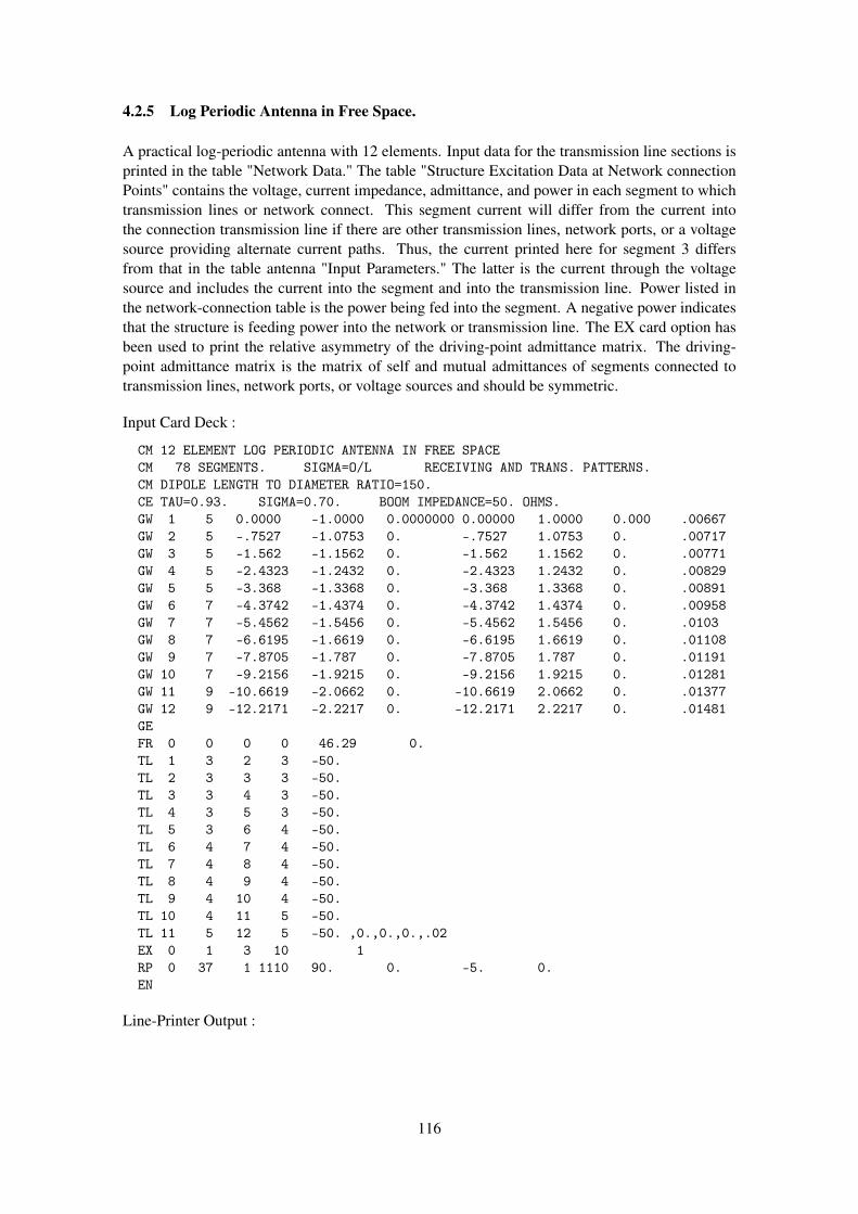
4.2.5 Log Periodic Antenna in Free Space.
A practical log-periodic antenna with 12 elements. Input data for the transmission line sections isprinted in the table "Network Data." The table "Structure Excitation Data at Network connectionPoints" contains the voltage, current impedance, admittance, and power in each segment to whichtransmission lines or network connect. This segment current will differ from the current intothe connection transmission line if there are other transmission lines, network ports, or a voltagesource providing alternate current paths. Thus, the current printed here for segment 3 differsfrom that in the table antenna "Input Parameters." The latter is the current through the voltagesource and includes the current into the segment and into the transmission line. Power listed inthe network-connection table is the power being fed into the segment. A negative power indicatesthat the structure is feeding power into the network or transmission line. The EX card option hasbeen used to print the relative asymmetry of the driving-point admittance matrix. The driving-point admittance matrix is the matrix of self and mutual admittances of segments connected totransmission lines, network ports, or voltage sources and should be symmetric.
Input Card Deck :
CM 12 ELEMENT LOG PERIODIC ANTENNA IN FREE SPACECM 78 SEGMENTS. SIGMA=O/L RECEIVING AND TRANS. PATTERNS.CM DIPOLE LENGTH TO DIAMETER RATIO=150.CE TAU=0.93. SIGMA=0.70. BOOM IMPEDANCE=50. OHMS.GW 1 5 0.0000 -1.0000 0.0000000 0.00000 1.0000 0.000 .00667GW 2 5 -.7527 -1.0753 0. -.7527 1.0753 0. .00717GW 3 5 -1.562 -1.1562 0. -1.562 1.1562 0. .00771GW 4 5 -2.4323 -1.2432 0. -2.4323 1.2432 0. .00829GW 5 5 -3.368 -1.3368 0. -3.368 1.3368 0. .00891GW 6 7 -4.3742 -1.4374 0. -4.3742 1.4374 0. .00958GW 7 7 -5.4562 -1.5456 0. -5.4562 1.5456 0. .0103GW 8 7 -6.6195 -1.6619 0. -6.6195 1.6619 0. .01108GW 9 7 -7.8705 -1.787 0. -7.8705 1.787 0. .01191GW 10 7 -9.2156 -1.9215 0. -9.2156 1.9215 0. .01281GW 11 9 -10.6619 -2.0662 0. -10.6619 2.0662 0. .01377GW 12 9 -12.2171 -2.2217 0. -12.2171 2.2217 0. .01481GEFR 0 0 0 0 46.29 0.TL 1 3 2 3 -50.TL 2 3 3 3 -50.TL 3 3 4 3 -50.TL 4 3 5 3 -50.TL 5 3 6 4 -50.TL 6 4 7 4 -50.TL 7 4 8 4 -50.TL 8 4 9 4 -50.TL 9 4 10 4 -50.TL 10 4 11 5 -50.TL 11 5 12 5 -50. ,0.,0.,0.,.02EX 0 1 3 10 1RP 0 37 1 1110 90. 0. -5. 0.EN
Line-Printer Output :
116

****
****
****
****
****
****
****
****
****
NUME
RICA
LEL
ECTR
OMAG
NETI
CSCO
DE
****
****
****
****
****
****
****
****
****
--
--
COMM
ENTS
--
--
12EL
EMEN
TLO
GPE
RIOD
ICAN
TENN
AIN
FREE
SPAC
E78
SEGM
ENTS
.SI
GMA=
O/L
RECE
IVIN
GAN
DTR
ANS.
PATT
ERNS
.DI
POLE
LENG
THTO
DIAM
ETER
RATI
O=15
0.TA
U=0.
93.
SIGM
A=0.
70.
BOOM
IMPE
DANC
E=50
.OH
MS.
--
-ST
RUCT
URE
SPEC
IFIC
ATIO
N-
--
COOR
DINA
TES
MUST
BEIN
PUT
INME
TERS
ORBE
SCAL
EDTO
METE
RSBE
FORE
STRU
CTUR
EIN
PUT
ISEN
DED
WIRE
NO.
OFFI
RST
LAST
TAG
NO.
X1Y1
Z1X2
Y2Z2
RADI
USSE
G.SE
G.SE
G.NO
.1
.000
00-1
.000
00.0
0000
.000
001.
0000
0.0
0000
.006
675
15
12
-.75
270
-1.0
7530
.000
00-.
7527
01.
0753
0.0
0000
.007
175
610
23
-1.5
6200
-1.1
5620
.000
00-1
.562
001.
1562
0.0
0000
.007
715
1115
34
-2.4
3230
-1.2
4320
.000
00-2
.432
301.
2432
0.0
0000
.008
295
1620
45
-3.3
6800
-1.3
3680
.000
00-3
.368
001.
3368
0.0
0000
.008
915
2125
56
-4.3
7420
-1.4
3740
.000
00-4
.374
201.
4374
0.0
0000
.009
587
2632
67
-5.4
5620
-1.5
4560
.000
00-5
.456
201.
5456
0.0
0000
.010
307
3339
78
-6.6
1950
-1.6
6190
.000
00-6
.619
501.
6619
0.0
0000
.011
087
4046
89
-7.8
7050
-1.7
8700
.000
00-7
.870
501.
7870
0.0
0000
.011
917
4753
910
-9.2
1560
-1.9
2150
.000
00-9
.215
601.
9215
0.0
0000
.012
817
5460
1011
-10.
6619
0-2
.066
20.0
0000
-10.
6619
02.
0662
0.0
0000
.013
779
6169
1112
-12.
2171
0-2
.221
70.0
0000
-12.
2171
02.
2217
0.0
0000
.014
819
7078
12
TOTA
LSE
GMEN
TSUS
ED=
78NO
.SE
G.IN
ASY
MMET
RIC
CELL
=78
SYMM
ETRY
FLAG
=0
117
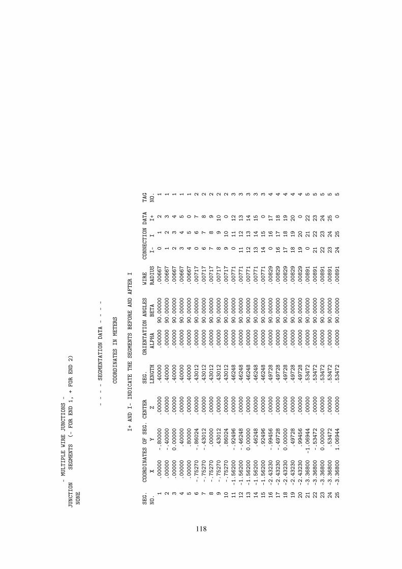
-MU
LTIP
LEWI
REJU
NCTI
ONS
-JU
NCTI
ONSE
GMEN
TS(-
FOR
END
1,+
FOR
END
2)NO
NE
--
--
SEGM
ENTA
TION
DATA
--
--
COOR
DINA
TES
INME
TERS
I+AN
DI-
INDI
CATE
THE
SEGM
ENTS
BEFO
REAN
DAF
TER
I
SEG.
COOR
DINA
TES
OFSE
G.CE
NTER
SEG.
ORIE
NTAT
ION
ANGL
ESWI
RECO
NNEC
TION
DATA
TAG
NO.
XY
ZLE
NGTH
ALPH
ABE
TARA
DIUS
I-I
I+NO
.1
.000
00-.
8000
0.0
0000
.400
00.0
0000
90.0
0000
.006
670
12
12
.000
00-.
4000
0.0
0000
.400
00.0
0000
90.0
0000
.006
671
23
13
.000
000.
0000
0.0
0000
.400
00.0
0000
90.0
0000
.006
672
34
14
.000
00.4
0000
.000
00.4
0000
.000
0090
.000
00.0
0667
34
51
5.0
0000
.800
00.0
0000
.400
00.0
0000
90.0
0000
.006
674
50
16
-.75
270
-.86
024
.000
00.4
3012
.000
0090
.000
00.0
0717
06
72
7-.
7527
0-.
4301
2.0
0000
.430
12.0
0000
90.0
0000
.007
176
78
28
-.75
270
.000
00.0
0000
.430
12.0
0000
90.0
0000
.007
177
89
29
-.75
270
.430
12.0
0000
.430
12.0
0000
90.0
0000
.007
178
910
210
-.75
270
.860
24.0
0000
.430
12.0
0000
90.0
0000
.007
179
100
211
-1.5
6200
-.92
496
.000
00.4
6248
.000
0090
.000
00.0
0771
011
123
12-1
.562
00-.
4624
8.0
0000
.462
48.0
0000
90.0
0000
.007
7111
1213
313
-1.5
6200
0.00
000
.000
00.4
6248
.000
0090
.000
00.0
0771
1213
143
14-1
.562
00.4
6248
.000
00.4
6248
.000
0090
.000
00.0
0771
1314
153
15-1
.562
00.9
2496
.000
00.4
6248
.000
0090
.000
00.0
0771
1415
03
16-2
.432
30-.
9945
6.0
0000
.497
28.0
0000
90.0
0000
.008
290
1617
417
-2.4
3230
-.49
728
.000
00.4
9728
.000
0090
.000
00.0
0829
1617
184
18-2
.432
300.
0000
0.0
0000
.497
28.0
0000
90.0
0000
.008
2917
1819
419
-2.4
3230
.497
28.0
0000
.497
28.0
0000
90.0
0000
.008
2918
1920
420
-2.4
3230
.994
56.0
0000
.497
28.0
0000
90.0
0000
.008
2919
200
421
-3.3
6800
-1.0
6944
.000
00.5
3472
.000
0090
.000
00.0
0891
021
225
22-3
.368
00-.
5347
2.0
0000
.534
72.0
0000
90.0
0000
.008
9121
2223
523
-3.3
6800
0.00
000
.000
00.5
3472
.000
0090
.000
00.0
0891
2223
245
24-3
.368
00.5
3472
.000
00.5
3472
.000
0090
.000
00.0
0891
2324
255
25-3
.368
001.
0694
4.0
0000
.534
72.0
0000
90.0
0000
.008
9124
250
5
118

26-4
.374
20-1
.232
06.0
0000
.410
69.0
0000
90.0
0000
.009
580
2627
627
-4.3
7420
-.82
137
.000
00.4
1069
.000
0090
.000
00.0
0958
2627
286
28-4
.374
20-.
4106
9.0
0000
.410
69.0
0000
90.0
0000
.009
5827
2829
629
-4.3
7420
0.00
000
.000
00.4
1069
.000
0090
.000
00.0
0958
2829
306
30-4
.374
20.4
1069
.000
00.4
1069
.000
0090
.000
00.0
0958
2930
316
31-4
.374
20.8
2137
.000
00.4
1069
.000
0090
.000
00.0
0958
3031
326
32-4
.374
201.
2320
6.0
0000
.410
69.0
0000
90.0
0000
.009
5831
320
633
-5.4
5620
-1.3
2480
.000
00.4
4160
.000
0090
.000
00.0
1030
033
347
34-5
.456
20-.
8832
0.0
0000
.441
60.0
0000
90.0
0000
.010
3033
3435
735
-5.4
5620
-.44
160
.000
00.4
4160
.000
0090
.000
00.0
1030
3435
367
36-5
.456
200.
0000
0.0
0000
.441
60.0
0000
90.0
0000
.010
3035
3637
737
-5.4
5620
.441
60.0
0000
.441
60.0
0000
90.0
0000
.010
3036
3738
738
-5.4
5620
.883
20.0
0000
.441
60.0
0000
90.0
0000
.010
3037
3839
739
-5.4
5620
1.32
480
.000
00.4
4160
.000
0090
.000
00.0
1030
3839
07
40-6
.619
50-1
.424
49.0
0000
.474
83.0
0000
90.0
0000
.011
080
4041
841
-6.6
1950
-.94
966
.000
00.4
7483
.000
0090
.000
00.0
1108
4041
428
42-6
.619
50-.
4748
3.0
0000
.474
83.0
0000
90.0
0000
.011
0841
4243
843
-6.6
1950
0.00
000
.000
00.4
7483
.000
0090
.000
00.0
1108
4243
448
44-6
.619
50.4
7483
.000
00.4
7483
.000
0090
.000
00.0
1108
4344
458
45-6
.619
50.9
4966
.000
00.4
7483
.000
0090
.000
00.0
1108
4445
468
46-6
.619
501.
4244
9.0
0000
.474
83.0
0000
90.0
0000
.011
0845
460
847
-7.8
7050
-1.5
3171
.000
00.5
1057
.000
0090
.000
00.0
1191
047
489
48-7
.870
50-1
.021
14.0
0000
.510
57.0
0000
90.0
0000
.011
9147
4849
949
-7.8
7050
-.51
057
.000
00.5
1057
.000
0090
.000
00.0
1191
4849
509
50-7
.870
500.
0000
0.0
0000
.510
57.0
0000
90.0
0000
.011
9149
5051
951
-7.8
7050
.510
57.0
0000
.510
57.0
0000
90.0
0000
.011
9150
5152
952
-7.8
7050
1.02
114
.000
00.5
1057
.000
0090
.000
00.0
1191
5152
539
53-7
.870
501.
5317
1.0
0000
.510
57.0
0000
90.0
0000
.011
9152
530
954
-9.2
1560
-1.6
4700
.000
00.5
4900
.000
0090
.000
00.0
1281
054
5510
55-9
.215
60-1
.098
00.0
0000
.549
00.0
0000
90.0
0000
.012
8154
5556
1056
-9.2
1560
-.54
900
.000
00.5
4900
.000
0090
.000
00.0
1281
5556
5710
57-9
.215
600.
0000
0.0
0000
.549
00.0
0000
90.0
0000
.012
8156
5758
1058
-9.2
1560
.549
00.0
0000
.549
00.0
0000
90.0
0000
.012
8157
5859
1059
-9.2
1560
1.09
800
.000
00.5
4900
.000
0090
.000
00.0
1281
5859
6010
60-9
.215
601.
6470
0.0
0000
.549
00.0
0000
90.0
0000
.012
8159
600
1061
-10.
6619
0-1
.836
62.0
0000
.459
16.0
0000
90.0
0000
.013
770
6162
1162
-10.
6619
0-1
.377
47.0
0000
.459
16.0
0000
90.0
0000
.013
7761
6263
1163
-10.
6619
0-.
9183
1.0
0000
.459
16.0
0000
90.0
0000
.013
7762
6364
11
119

64-1
0.66
190
-.45
916
.000
00.4
5916
.000
0090
.000
00.0
1377
6364
6511
65-1
0.66
190
.000
00.0
0000
.459
16.0
0000
90.0
0000
.013
7764
6566
1166
-10.
6619
0.4
5916
.000
00.4
5916
.000
0090
.000
00.0
1377
6566
6711
67-1
0.66
190
.918
31.0
0000
.459
16.0
0000
90.0
0000
.013
7766
6768
1168
-10.
6619
01.
3774
7.0
0000
.459
16.0
0000
90.0
0000
.013
7767
6869
1169
-10.
6619
01.
8366
2.0
0000
.459
16.0
0000
90.0
0000
.013
7768
690
1170
-12.
2171
0-1
.974
84.0
0000
.493
71.0
0000
90.0
0000
.014
810
7071
1271
-12.
2171
0-1
.481
13.0
0000
.493
71.0
0000
90.0
0000
.014
8170
7172
1272
-12.
2171
0-.
9874
2.0
0000
.493
71.0
0000
90.0
0000
.014
8171
7273
1273
-12.
2171
0-.
4937
1.0
0000
.493
71.0
0000
90.0
0000
.014
8172
7374
1274
-12.
2171
00.
0000
0.0
0000
.493
71.0
0000
90.0
0000
.014
8173
7475
1275
-12.
2171
0.4
9371
.000
00.4
9371
.000
0090
.000
00.0
1481
7475
7612
76-1
2.21
710
.987
42.0
0000
.493
71.0
0000
90.0
0000
.014
8175
7677
1277
-12.
2171
01.
4811
3.0
0000
.493
71.0
0000
90.0
0000
.014
8176
7778
1278
-12.
2171
01.
9748
4.0
0000
.493
71.0
0000
90.0
0000
.014
8177
780
12
****
*DA
TACA
RDNO
.1
FR0
00
04.
6290
0E+0
10.
0000
0E-0
10.
0000
0E-0
10.
0000
0E-0
10.
0000
0E-0
10.
0000
0E-0
1**
***
DATA
CARD
NO.
2TL
13
23
-5.0
0000
E+01
0.00
000E
-01
0.00
000E
-01
0.00
000E
-01
0.00
000E
-01
0.00
000E
-01
****
*DA
TACA
RDNO
.3
TL2
33
3-5
.000
00E+
010.
0000
0E-0
10.
0000
0E-0
10.
0000
0E-0
10.
0000
0E-0
10.
0000
0E-0
1**
***
DATA
CARD
NO.
4TL
33
43
-5.0
0000
E+01
0.00
000E
-01
0.00
000E
-01
0.00
000E
-01
0.00
000E
-01
0.00
000E
-01
****
*DA
TACA
RDNO
.5
TL4
35
3-5
.000
00E+
010.
0000
0E-0
10.
0000
0E-0
10.
0000
0E-0
10.
0000
0E-0
10.
0000
0E-0
1**
***
DATA
CARD
NO.
6TL
53
64
-5.0
0000
E+01
0.00
000E
-01
0.00
000E
-01
0.00
000E
-01
0.00
000E
-01
0.00
000E
-01
****
*DA
TACA
RDNO
.7
TL6
47
4-5
.000
00E+
010.
0000
0E-0
10.
0000
0E-0
10.
0000
0E-0
10.
0000
0E-0
10.
0000
0E-0
1**
***
DATA
CARD
NO.
8TL
74
84
-5.0
0000
E+01
0.00
000E
-01
0.00
000E
-01
0.00
000E
-01
0.00
000E
-01
0.00
000E
-01
****
*DA
TACA
RDNO
.9
TL8
49
4-5
.000
00E+
010.
0000
0E-0
10.
0000
0E-0
10.
0000
0E-0
10.
0000
0E-0
10.
0000
0E-0
1**
***
DATA
CARD
NO.
10TL
94
104
-5.0
0000
E+01
0.00
000E
-01
0.00
000E
-01
0.00
000E
-01
0.00
000E
-01
0.00
000E
-01
****
*DA
TACA
RDNO
.11
TL10
411
5-5
.000
00E+
010.
0000
0E-0
10.
0000
0E-0
10.
0000
0E-0
10.
0000
0E-0
10.
0000
0E-0
1**
***
DATA
CARD
NO.
12TL
115
125
-5.0
0000
E+01
0.00
000E
-01
0.00
000E
-01
0.00
000E
-01
2.00
000E
-02
0.00
000E
-01
****
*DA
TACA
RDNO
.13
EX0
13
101.
0000
0E+0
00.
0000
0E-0
10.
0000
0E-0
10.
0000
0E-0
10.
0000
0E-0
10.
0000
0E-0
1**
***
DATA
CARD
NO.
14RP
037
111
109.
0000
0E+0
10.
0000
0E-0
1-5
.000
00E+
000.
0000
0E-0
10.
0000
0E-0
10.
0000
0E-0
1
--
--
--
FREQ
UENC
Y-
--
--
-
FREQ
UENC
Y=4.
6290
E+01
MHZ
WAVE
LENG
TH=
6.47
66E+
00ME
TERS
120
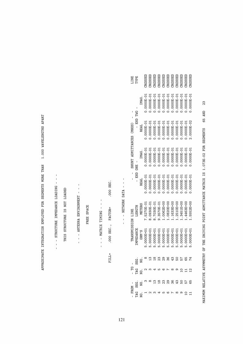
APPR
OXIM
ATE
INTE
GRAT
ION
EMPL
OYED
FOR
SEGM
ENTS
MORE
THAN
1.00
0WA
VELE
NGTH
SAP
ART
--
-ST
RUCT
URE
IMPE
DANC
ELO
ADIN
G-
--
THIS
STRU
CTUR
EIS
NOT
LOAD
ED
--
-AN
TENN
AEN
VIRO
NMEN
T-
--
FREE
SPAC
E
--
-MA
TRIX
TIMI
NG-
--
FILL
=.0
00SE
C.,
FACT
OR=
.000
SEC.
--
-NE
TWOR
KDA
TA-
--
-FR
OM-
-TO
-TR
ANSM
ISSI
ONLI
NE-
-SH
UNT
ADMI
TTAN
CES
(MHO
S)-
-LI
NETA
GSE
G.TA
GSE
G.IM
PEDA
NCE
LENG
TH-
END
ONE
--
END
TWO
-TY
PENO
.NO
.NO
.NO
.OH
M’S
METE
RSRE
ALIM
AG.
REAL
IMAG
.1
32
85.
0000
E+01
7.52
70E-
010.
0000
E-01
0.00
00E-
010.
0000
E-01
0.00
00E-
01CR
OSSE
D2
83
135.
0000
E+01
8.09
30E-
010.
0000
E-01
0.00
00E-
010.
0000
E-01
0.00
00E-
01CR
OSSE
D3
134
185.
0000
E+01
8.70
30E-
010.
0000
E-01
0.00
00E-
010.
0000
E-01
0.00
00E-
01CR
OSSE
D4
185
235.
0000
E+01
9.35
70E-
010.
0000
E-01
0.00
00E-
010.
0000
E-01
0.00
00E-
01CR
OSSE
D5
236
295.
0000
E+01
1.00
62E+
000.
0000
E-01
0.00
00E-
010.
0000
E-01
0.00
00E-
01CR
OSSE
D6
297
365.
0000
E+01
1.08
20E+
000.
0000
E-01
0.00
00E-
010.
0000
E-01
0.00
00E-
01CR
OSSE
D7
368
435.
0000
E+01
1.16
33E+
000.
0000
E-01
0.00
00E-
010.
0000
E-01
0.00
00E-
01CR
OSSE
D8
439
505.
0000
E+01
1.25
10E+
000.
0000
E-01
0.00
00E-
010.
0000
E-01
0.00
00E-
01CR
OSSE
D9
5010
575.
0000
E+01
1.34
51E+
000.
0000
E-01
0.00
00E-
010.
0000
E-01
0.00
00E-
01CR
OSSE
D10
5711
655.
0000
E+01
1.44
63E+
000.
0000
E-01
0.00
00E-
010.
0000
E-01
0.00
00E-
01CR
OSSE
D11
6512
745.
0000
E+01
1.55
52E+
000.
0000
E-01
0.00
00E-
012.
0000
E-02
0.00
00E-
01CR
OSSE
D
MAXI
MUM
RELA
TIVE
ASYM
METR
YOF
THE
DRIV
ING
POIN
TAD
MITT
ANCE
MATR
IXIS
1.07
3E-0
2FO
RSE
GMEN
TS65
AND
23
121
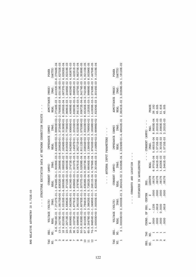
RMS
RELA
TIVE
ASYM
METR
YIS
5.72
2E-0
3
--
-ST
RUCT
URE
EXCI
TATI
ONDA
TAAT
NETW
ORK
CONN
ECTI
ONPO
INTS
--
-
TAG
SEG.
VOLT
AGE
(VOL
TS)
CURR
ENT
(AMP
S)IM
PEDA
NCE
(OHM
S)AD
MITT
ANCE
(MHO
S)PO
WER
NO.
NO.
REAL
IMAG
.RE
ALIM
AG.
REAL
IMAG
.RE
ALIM
AG.
(WAT
TS)
28-
6.76
616E
-01
7.27
107E
-01-
1.87
448E
-04-
1.90
086E
-03-
3.44
068E
+02-
3.89
883E
+02-
1.27
248E
-03
1.44
192E
-03-
6.27
648E
-04
313
-1.1
4179
E-01
-1.0
8175
E+00
6.83
832E
-03
2.28
689E
-03-
6.25
982E
+01-
1.37
256E
+02-
2.75
065E
-03
6.03
119E
-03-
1.62
732E
-03
418
9.62
183E
-01
5.03
150E
-01-
4.58
059E
-03
1.06
832E
-02
7.16
349E
+00-
9.31
369E
+01
8.20
955E
-04
1.06
737E
-02
4.83
935E
-04
523
-7.2
4713
E-01
6.58
962E
-01-
1.37
152E
-02-
3.48
003E
-03
3.81
905E
+01-
5.77
365E
+01
7.96
961E
-03
1.20
485E
-02
3.82
318E
-03
629
-2.8
0596
E-01
-7.5
6236
E-01
1.69
124E
-03-
1.27
472E
-02
5.54
295E
+01-
2.93
665E
+01
1.40
869E
-02
7.46
324E
-03
4.58
267E
-03
736
5.10
270E
-01
5.67
761E
-02
9.62
865E
-03-
1.20
107E
-03
5.14
587E
+01
1.23
155E
+01
1.83
803E
-02-
4.39
892E
-03
2.42
251E
-03
843
-2.4
4964
E-01
2.99
215E
-01
1.37
879E
-03
5.04
751E
-03
4.28
271E
+01
6.02
303E
+01
7.84
113E
-03-
1.10
275E
-02
5.86
270E
-04
950
-9.8
1928
E-02
-3.6
0792
E-01
-2.3
0707
E-03
5.52
838E
-04
4.81
112E
+00
1.57
539E
+02
1.93
672E
-04-
6.34
174E
-03
1.35
389E
-05
1057
3.40
100E
-01
2.78
461E
-02
3.63
826E
-04-
9.09
073E
-04
1.02
654E
+02
3.33
033E
+02
8.45
245E
-04-
2.74
216E
-03
4.92
115E
-05
1165
-9.2
5478
E-02
3.38
625E
-01
5.72
652E
-04
5.66
045E
-04
2.13
900E
+02
3.79
895E
+02
1.12
535E
-03-
1.99
868E
-03
6.93
396E
-05
1274
-2.9
4654
E-01
-1.3
4965
E-01
-7.2
4811
E-04
4.78
766E
-04
1.97
400E
+02
3.16
598E
+02
1.41
809E
-03-
2.27
439E
-03
7.44
759E
-05
13
1.00
000E
+00
0.00
000E
-01
1.82
304E
-03
2.30
145E
-03
2.11
486E
+02-
2.66
986E
+02
1.82
304E
-03
2.30
145E
-03
9.11
518E
-04
--
-AN
TENN
AIN
PUT
PARA
METE
RS-
--
TAG
SEG.
VOLT
AGE
(VOL
TS)
CURR
ENT
(AMP
S)IM
PEDA
NCE
(OHM
S)AD
MITT
ANCE
(MHO
S)PO
WER
NO.
NO.
REAL
IMAG
.RE
ALIM
AG.
REAL
IMAG
.RE
ALIM
AG.
(WAT
TS)
13
1.00
000E
+00
0.00
000E
-01
2.36
241E
-02
2.50
358E
-04
4.23
249E
+01-
4.48
542E
-01
2.36
241E
-02
2.50
358E
-04
1.18
120E
-02
--
-CU
RREN
TSAN
DLO
CATI
ON-
--
DIST
ANCE
SIN
WAVE
LENG
THS
SEG.
TAG
COOR
D.OF
SEG.
CENT
ERSE
G.-
--
CURR
ENT
(AMP
S)-
--
NO.
NO.
XY
ZLE
NGTH
REAL
IMAG
.MA
G.PH
ASE
11
.000
0-.
1235
.000
0.0
6176
6.97
01E-
045.
6831
E-04
8.99
33E-
0439
.192
21
.000
0-.
0618
.000
0.0
6176
1.54
41E-
031.
5715
E-03
2.20
31E-
0345
.505
31
.000
00.
0000
.000
0.0
6176
1.82
30E-
032.
3015
E-03
2.93
60E-
0351
.616
41
.000
0.0
618
.000
0.0
6176
1.54
41E-
031.
5715
E-03
2.20
31E-
0345
.505
122
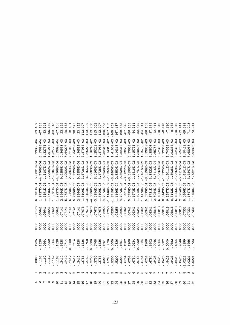
51
.000
0.1
235
.000
0.0
6176
6.97
01E-
045.
6831
E-04
8.99
33E-
0439
.192
62
-.11
62-.
1328
.000
0.0
6641
1.99
27E-
04-4
.736
9E-0
45.
1389
E-04
-67.
185
72
-.11
62-.
0664
.000
0.0
6641
1.53
91E-
04-1
.318
7E-0
31.
3277
E-03
-83.
343
82
-.11
62.0
000
.000
0.0
6641
-1.8
745E
-04
-1.9
009E
-03
1.91
01E-
03-9
5.63
29
2-.
1162
.066
4.0
000
.066
411.
5391
E-04
-1.3
187E
-03
1.32
77E-
03-8
3.34
310
2-.
1162
.132
8.0
000
.066
411.
9927
E-04
-4.7
369E
-04
5.13
89E-
04-6
7.18
511
3-.
2412
-.14
28.0
000
.071
412.
1564
E-03
9.22
55E-
042.
3455
E-03
23.1
6212
3-.
2412
-.07
14.0
000
.071
415.
2787
E-03
1.99
20E-
035.
6420
E-03
20.6
7513
3-.
2412
0.00
00.0
000
.071
416.
8383
E-03
2.28
69E-
037.
2106
E-03
18.4
9114
3-.
2412
.071
4.0
000
.071
415.
2786
E-03
1.99
20E-
035.
6420
E-03
20.6
7515
3-.
2412
.142
8.0
000
.071
412.
1564
E-03
9.22
55E-
042.
3455
E-03
23.1
6216
4-.
3756
-.15
36.0
000
.076
78-1
.510
0E-0
33.
5736
E-03
3.87
95E-
0311
2.90
717
4-.
3756
-.07
68.0
000
.076
78-3
.615
4E-0
38.
5166
E-03
9.25
22E-
0311
3.00
218
4-.
3756
0.00
00.0
000
.076
78-4
.580
6E-0
31.
0683
E-02
1.16
24E-
0211
3.20
819
4-.
3756
.076
8.0
000
.076
78-3
.615
4E-0
38.
5165
E-03
9.25
22E-
0311
3.00
220
4-.
3756
.153
6.0
000
.076
78-1
.510
0E-0
33.
5736
E-03
3.87
95E-
0311
2.90
721
5-.
5200
-.16
51.0
000
.082
56-4
.727
3E-0
3-9
.563
8E-0
44.
8231
E-03
-168
.563
225
-.52
00-.
0826
.000
0.0
8256
-1.1
146E
-02
-2.5
350E
-03
1.14
31E-
02-1
67.1
8723
5-.
5200
0.00
00.0
000
.082
56-1
.371
5E-0
2-3
.480
0E-0
31.
4150
E-02
-165
.762
245
-.52
00.0
826
.000
0.0
8256
-1.1
146E
-02
-2.5
350E
-03
1.14
31E-
02-1
67.1
8725
5-.
5200
.165
1.0
000
.082
56-4
.727
3E-0
3-9
.563
8E-0
44.
8231
E-03
-168
.563
266
-.67
54-.
1902
.000
0.0
6341
1.37
31E-
04-3
.382
2E-0
33.
3850
E-03
-87.
675
276
-.67
54-.
1268
.000
0.0
6341
5.57
99E-
04-8
.319
8E-0
38.
3385
E-03
-86.
163
286
-.67
54-.
0634
.000
0.0
6341
1.14
73E-
03-1
.151
6E-0
21.
1573
E-02
-84.
311
296
-.67
540.
0000
.000
0.0
6341
1.69
12E-
03-1
.274
7E-0
21.
2859
E-02
-82.
442
306
-.67
54.0
634
.000
0.0
6341
1.14
73E-
03-1
.151
6E-0
21.
1573
E-02
-84.
311
316
-.67
54.1
268
.000
0.0
6341
5.57
99E-
04-8
.319
9E-0
38.
3385
E-03
-86.
163
326
-.67
54.1
902
.000
0.0
6341
1.37
31E-
04-3
.382
2E-0
33.
3850
E-03
-87.
675
337
-.84
25-.
2046
.000
0.0
6818
2.59
54E-
03-5
.711
6E-0
42.
6575
E-03
-12.
411
347
-.84
25-.
1364
.000
0.0
6818
6.40
66E-
03-1
.226
8E-0
36.
5230
E-03
-10.
840
357
-.84
25-.
0682
.000
0.0
6818
8.81
42E-
03-1
.392
5E-0
38.
9235
E-03
-8.9
7836
7-.
8425
0.00
00.0
000
.068
189.
6287
E-03
-1.2
011E
-03
9.70
33E-
03-7
.110
377
-.84
25.0
682
.000
0.0
6818
8.81
42E-
03-1
.392
5E-0
38.
9235
E-03
-8.9
7838
7-.
8425
.136
4.0
000
.068
186.
4066
E-03
-1.2
268E
-03
6.52
30E-
03-1
0.84
039
7-.
8425
.204
6.0
000
.068
182.
5954
E-03
-5.7
116E
-04
2.65
75E-
03-1
2.41
140
8-1
.022
1-.
2199
.000
0.0
7331
5.24
66E-
041.
4101
E-03
1.50
45E-
0369
.591
418
-1.0
221
-.14
66.0
000
.073
311.
1847
E-03
3.48
47E-
033.
6806
E-03
71.2
2342
8-1
.022
1-.
0733
.000
0.0
7331
1.44
58E-
034.
7321
E-03
4.94
80E-
0373
.011
123

438
-1.0
221
0.00
00.0
000
.073
311.
3788
E-03
5.04
75E-
035.
2324
E-03
74.7
2244
8-1
.022
1.0
733
.000
0.0
7331
1.44
58E-
034.
7321
E-03
4.94
80E-
0373
.011
458
-1.0
221
.146
6.0
000
.073
311.
1847
E-03
3.48
47E-
033.
6806
E-03
71.2
2346
8-1
.022
1.2
199
.000
0.0
7331
5.24
66E-
041.
4101
E-03
1.50
45E-
0369
.591
479
-1.2
152
-.23
65.0
000
.078
83-7
.426
6E-0
42.
0200
E-04
7.69
64E-
0416
4.78
448
9-1
.215
2-.
1577
.000
0.0
7883
-1.7
935E
-03
4.61
91E-
041.
8521
E-03
165.
558
499
-1.2
152
-.07
88.0
000
.078
83-2
.319
2E-0
35.
7096
E-04
2.38
84E-
0316
6.16
950
9-1
.215
20.
0000
.000
0.0
7883
-2.3
071E
-03
5.52
84E-
042.
3724
E-03
166.
524
519
-1.2
152
.078
8.0
000
.078
83-2
.319
2E-0
35.
7096
E-04
2.38
84E-
0316
6.16
952
9-1
.215
2.1
577
.000
0.0
7883
-1.7
935E
-03
4.61
91E-
041.
8521
E-03
165.
558
539
-1.2
152
.236
5.0
000
.078
83-7
.426
6E-0
42.
0200
E-04
7.69
64E-
0416
4.78
454
10-1
.422
9-.
2543
.000
0.0
8477
9.57
43E-
05-3
.908
7E-0
44.
0242
E-04
-76.
236
5510
-1.4
229
-.16
95.0
000
.084
772.
4938
E-04
-8.9
773E
-04
9.31
73E-
04-7
4.47
556
10-1
.422
9-.
0848
.000
0.0
8477
3.45
15E-
04-1
.056
3E-0
31.
1113
E-03
-71.
906
5710
-1.4
229
0.00
00.0
000
.084
773.
6383
E-04
-9.0
907E
-04
9.79
17E-
04-6
8.18
858
10-1
.422
9.0
848
.000
0.0
8477
3.45
15E-
04-1
.056
3E-0
31.
1113
E-03
-71.
906
5910
-1.4
229
.169
5.0
000
.084
772.
4938
E-04
-8.9
773E
-04
9.31
73E-
04-7
4.47
560
10-1
.422
9.2
543
.000
0.0
8477
9.57
43E-
05-3
.908
7E-0
44.
0242
E-04
-76.
236
6111
-1.6
462
-.28
36.0
000
.070
892.
7079
E-04
1.50
10E-
043.
0961
E-04
28.9
9962
11-1
.646
2-.
2127
.000
0.0
7089
6.32
52E-
043.
7761
E-04
7.36
67E-
0430
.837
6311
-1.6
462
-.14
18.0
000
.070
898.
0839
E-04
5.32
76E-
049.
6816
E-04
33.3
8664
11-1
.646
2-.
0709
.000
0.0
7089
7.68
74E-
045.
9415
E-04
9.71
59E-
0437
.700
6511
-1.6
462
.000
0.0
000
.070
895.
7265
E-04
5.66
04E-
048.
0519
E-04
44.6
6866
11-1
.646
2.0
709
.000
0.0
7089
7.68
74E-
045.
9415
E-04
9.71
58E-
0437
.700
6711
-1.6
462
.141
8.0
000
.070
898.
0839
E-04
5.32
76E-
049.
6815
E-04
33.3
8668
11-1
.646
2.2
127
.000
0.0
7089
6.32
52E-
043.
7761
E-04
7.36
66E-
0430
.837
6911
-1.6
462
.283
6.0
000
.070
892.
7079
E-04
1.50
10E-
043.
0960
E-04
28.9
9970
12-1
.886
4-.
3049
.000
0.0
7623
-1.9
982E
-04
2.40
71E-
043.
1284
E-04
129.
697
7112
-1.8
864
-.22
87.0
000
.076
23-5
.050
0E-0
45.
6306
E-04
7.56
35E-
0413
1.88
872
12-1
.886
4-.
1525
.000
0.0
7623
-7.0
915E
-04
7.14
96E-
041.
0070
E-03
134.
767
7312
-1.8
864
-.07
62.0
000
.076
23-7
.787
9E-0
46.
6719
E-04
1.02
55E-
0313
9.41
374
12-1
.886
40.
0000
.000
0.0
7623
-7.2
481E
-04
4.78
77E-
048.
6866
E-04
146.
554
7512
-1.8
864
.076
2.0
000
.076
23-7
.787
9E-0
46.
6719
E-04
1.02
55E-
0313
9.41
376
12-1
.886
4.1
525
.000
0.0
7623
-7.0
915E
-04
7.14
96E-
041.
0070
E-03
134.
767
7712
-1.8
864
.228
7.0
000
.076
23-5
.050
0E-0
45.
6306
E-04
7.56
35E-
0413
1.88
878
12-1
.886
4.3
049
.000
0.0
7623
-1.9
982E
-04
2.40
71E-
043.
1284
E-04
129.
697
124

--
-PO
WER
BUDG
ET-
--
INPU
TPO
WER
=1.
1812
E-02
WATT
SRA
DIAT
EDPO
WER=
1.07
62E-
02WA
TTS
STRU
CTUR
ELO
SS=
0.00
00E-
01WA
TTS
NETW
ORK
LOSS
=1.
0504
E-03
WATT
SEF
FICI
ENCY
=91
.11
PERC
ENT
--
-RA
DIAT
ION
PATT
ERNS
--
-
--
ANGL
ES-
--
DIRE
CTIV
EGA
INS
--
--
POLA
RIZA
TION
--
--
--
E(TH
ETA)
--
--
--
E(PH
I)-
--
THET
APH
IVE
RT.
HOR.
TOTA
LAX
IAL
TILT
SENS
EMA
GNIT
UDE
PHAS
EMA
GNIT
UDE
PHAS
EDE
GREE
SDE
GREE
SDB
DBDB
RATI
ODE
G.VO
LTS/
MDE
GREE
SVO
LTS/
MDE
GREE
S90
.00
.00
-999
.99
9.75
9.75
.000
0090
.00
LINE
AR0.
0000
0E-0
1.0
02.
4692
2E+0
0-6
6.00
85.0
0.0
0-9
99.9
99.
709.
70.0
0000
90.0
0LI
NEAR
0.00
000E
-01
.00
2.45
353E
+00
-65.
2080
.00
.00
-999
.99
9.53
9.53
.000
0090
.00
LINE
AR0.
0000
0E-0
1.0
02.
4069
0E+0
0-6
2.83
75.0
0.0
0-9
99.9
99.
259.
25.0
0000
90.0
0LI
NEAR
0.00
000E
-01
.00
2.33
094E
+00
-58.
9670
.00
.00
-999
.99
8.86
8.86
.000
0090
.00
LINE
AR0.
0000
0E-0
1.0
02.
2288
9E+0
0-5
3.74
65.0
0.0
0-9
99.9
98.
378.
37.0
0000
90.0
0LI
NEAR
0.00
000E
-01
.00
2.10
617E
+00
-47.
3060
.00
.00
-999
.99
7.79
7.79
.000
0090
.00
LINE
AR0.
0000
0E-0
1.0
01.
9702
4E+0
0-3
9.77
55.0
0.0
0-9
99.9
97.
157.
15.0
0000
90.0
0LI
NEAR
0.00
000E
-01
.00
1.82
917E
+00
-31.
1750
.00
.00
-999
.99
6.45
6.45
.000
0090
.00
LINE
AR0.
0000
0E-0
1.0
01.
6884
9E+0
0-2
1.34
45.0
0.0
0-9
99.9
95.
705.
70.0
0000
90.0
0LI
NEAR
0.00
000E
-01
.00
1.54
747E
+00
-9.9
140
.00
.00
-999
.99
4.81
4.81
.000
0090
.00
LINE
AR0.
0000
0E-0
1.0
01.
3975
9E+0
03.
5735
.00
.00
-999
.99
3.67
3.67
.000
0090
.00
LINE
AR0.
0000
0E-0
1.0
01.
2260
1E+0
019
.48
30.0
0.0
0-9
99.9
92.
102.
10.0
0000
90.0
0LI
NEAR
0.00
000E
-01
.00
1.02
313E
+00
38.0
225
.00
.00
-999
.99
-.14
-.14
.000
0090
.00
LINE
AR0.
0000
0E-0
1.0
07.
9031
4E-0
159
.26
20.0
0.0
0-9
99.9
9-3
.40
-3.4
0.0
0000
90.0
0LI
NEAR
0.00
000E
-01
.00
5.43
333E
-01
83.4
215
.00
.00
-999
.99
-8.2
7-8
.27
.000
0090
.00
LINE
AR0.
0000
0E-0
1.0
03.
1002
3E-0
111
1.77
10.0
0.0
0-9
99.9
9-1
6.15
-16.
15.0
0000
90.0
0LI
NEAR
0.00
000E
-01
.00
1.25
194E
-01
152.
575.
00.0
0-9
99.9
9-2
3.15
-23.
15.0
0000
90.0
0LI
NEAR
0.00
000E
-01
.00
5.58
629E
-02
-103
.82
.00
.00
-999
.99
-19.
63-1
9.63
.000
0090
.00
LINE
AR0.
0000
0E-0
1.0
08.
3785
5E-0
2-4
1.89
-5.0
0.0
0-9
99.9
9-2
0.66
-20.
66.0
0000
90.0
0LI
NEAR
0.00
000E
-01
.00
7.44
409E
-02
-24.
87-1
0.00
.00
-999
.99
-22.
14-2
2.14
.000
0090
.00
LINE
AR0.
0000
0E-0
1.0
06.
2757
8E-0
2-4
7.83
-15.
00.0
0-9
99.9
9-1
7.70
-17.
70.0
0000
90.0
0LI
NEAR
0.00
000E
-01
.00
1.04
649E
-01
-62.
63-2
0.00
.00
-999
.99
-14.
43-1
4.43
.000
0090
.00
LINE
AR0.
0000
0E-0
1.0
01.
5250
8E-0
1-5
0.23
-25.
00.0
0-9
99.9
9-1
3.31
-13.
31.0
0000
90.0
0LI
NEAR
0.00
000E
-01
.00
1.73
568E
-01
-30.
90
125
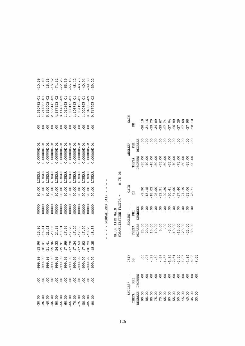
-30.
00.0
0-9
99.9
9-1
3.96
-13.
96.0
0000
90.0
0LI
NEAR
0.00
000E
-01
.00
1.61
079E
-01
-10.
69-3
5.00
.00
-999
.99
-16.
41-1
6.41
.000
0090
.00
LINE
AR0.
0000
0E-0
1.0
01.
2148
8E-0
17.
49-4
0.00
.00
-999
.99
-21.
41-2
1.41
.000
0090
.00
LINE
AR0.
0000
0E-0
1.0
06.
8324
0E-0
218
.31
-45.
00.0
0-9
99.9
9-2
9.95
-29.
95.0
0000
90.0
0LI
NEAR
0.00
000E
-01
.00
2.55
614E
-02
-16.
52-5
0.00
.00
-999
.99
-24.
33-2
4.33
.000
0090
.00
LINE
AR0.
0000
0E-0
1.0
04.
8779
2E-0
2-7
4.32
-55.
00.0
0-9
99.9
9-1
9.91
-19.
91.0
0000
90.0
0LI
NEAR
0.00
000E
-01
.00
8.11
455E
-02
-72.
25-6
0.00
.00
-999
.99
-17.
99-1
7.99
.000
0090
.00
LINE
AR0.
0000
0E-0
1.0
01.
0123
4E-0
1-6
3.59
-65.
00.0
0-9
99.9
9-1
7.28
-17.
28.0
0000
90.0
0LI
NEAR
0.00
000E
-01
.00
1.09
817E
-01
-55.
16-7
0.00
.00
-999
.99
-17.
24-1
7.24
.000
0090
.00
LINE
AR0.
0000
0E-0
1.0
01.
1037
1E-0
1-4
8.42
-75.
00.0
0-9
99.9
9-1
7.53
-17.
53.0
0000
90.0
0LI
NEAR
0.00
000E
-01
.00
1.06
719E
-01
-43.
73-8
0.00
.00
-999
.99
-17.
92-1
7.92
.000
0090
.00
LINE
AR0.
0000
0E-0
1.0
01.
0203
9E-0
1-4
0.94
-85.
00.0
0-9
99.9
9-1
8.23
-18.
23.0
0000
90.0
0LI
NEAR
0.00
000E
-01
.00
9.84
805E
-02
-39.
60-9
0.00
.00
-999
.99
-18.
35-1
8.35
.000
0090
.00
LINE
AR0.
0000
0E-0
1.0
09.
7179
9E-0
2-3
9.22
--
--
NORM
ALIZ
EDGA
IN-
--
-
MAJO
RAX
ISGA
INNO
RMAL
IZAT
ION
FACT
OR=
9.75
DB
--
ANGL
ES’
--
GAIN
--
ANGL
ES’
--
GAIN
--
ANGL
ES’
--
GAIN
THET
APH
IDB
THET
APH
IDB
THET
APH
IDB
DEGR
EES
DEGR
EES
DEGR
EES
DEGR
EES
DEGR
EES
DEGR
EES
90.0
0.0
0.0
025
.00
.00
-9.9
0-3
5.00
.00
-26.
1685
.00
.00
-.06
20.0
0.0
0-1
3.15
-40.
00.0
0-3
1.16
80.0
0.0
0-.
2215
.00
.00
-18.
02-4
5.00
.00
-39.
7075
.00
.00
-.50
10.0
0.0
0-2
5.90
-50.
00.0
0-3
4.09
70.0
0.0
0-.
895.
00.0
0-3
2.91
-55.
00.0
0-2
9.67
65.0
0.0
0-1
.38
.00
.00
-29.
39-6
0.00
.00
-27.
7460
.00
.00
-1.9
6-5
.00
.00
-30.
41-6
5.00
.00
-27.
0455
.00
.00
-2.6
1-1
0.00
.00
-31.
90-7
0.00
.00
-26.
9950
.00
.00
-3.3
0-1
5.00
.00
-27.
46-7
5.00
.00
-27.
2945
.00
.00
-4.0
6-2
0.00
.00
-24.
19-8
0.00
.00
-27.
6840
.00
.00
-4.9
4-2
5.00
.00
-23.
06-8
5.00
.00
-27.
9835
.00
.00
-6.0
8-3
0.00
.00
-23.
71-9
0.00
.00
-28.
1030
.00
.00
-7.6
5
126

****
*DA
TACA
RDNO
.15
EN0
00
00.
0000
0E-0
10.
0000
0E-0
10.
0000
0E-0
10.
0000
0E-0
10.
0000
0E-0
10.
0000
0E-0
1
RUN
TIME
=.0
00
127

4.2.6 Cylinder With Attached Wires.
The geometry data for the cylinder with attached wires was discussed in the examples at the endof Section 3.2. The wire on the end of the cylinder is excited first and a radiation pattern iscomputed. The CP card requests the coupling between the base segments of the two wires. Henceafter the second wire has been excited, the table "ISOLATION DATA" is printed. The couplingprinted is the maximum that would occur when the source and load are simultaneously matchedto there antennas. The table includes the matched load impedance for the second segment and thecorresponding input impedance at the firs segment. The source impedance would be the conjugateof this input impedance for maximum coupling.
(See Figure 21.)
Input Card Deck :
CECYLINDER WITH ATTACHED WIRESSP 0 0 10 0 7.3333 0. 0. 38.4SP 0 0 10 0 0. 0. 0. 38.4SP 0 0 10 0 -7.3333 0. 0. 38.4GM 0 1 0. 0. 30.SP 0 0 6.89 0. 11. 90. 0. 44.88SP 0 0 6.89 0. -11. -90. 0. 44.88GR 0 6SP 0 0 0. 0. 11. 90. 0. 44.89SP 0 0 0. 0. -11. -90. 0. 44.89GW 1 4 0. 0. 11. 0. 0. 23. .1GW 2 5 10. 0. 0. 27.6 0. 0. .2GS,0,0,.01GEFR,0,1,0,0,465.84CP 1 1 2 1EX 0 1 1 1.RP 0 73 1 1000 0. 0. 5. 0.EX 0 2 1 0 1.XQEN
Line-Printer Output :
128

****
****
****
****
****
****
****
****
****
NUME
RICA
LEL
ECTR
OMAG
NETI
CSCO
DE
****
****
****
****
****
****
****
****
****
--
--
COMM
ENTS
--
--
CYLI
NDER
WITH
ATTA
CHED
WIRE
S
--
-ST
RUCT
URE
SPEC
IFIC
ATIO
N-
--
COOR
DINA
TES
MUST
BEIN
PUT
INME
TERS
ORBE
SCAL
EDTO
METE
RSBE
FORE
STRU
CTUR
EIN
PUT
ISEN
DED
WIRE
NO.
OFFI
RST
LAST
TAG
NO.
X1Y1
Z1X2
Y2Z2
RADI
USSE
G.SE
G.SE
G.NO
.1P
10.0
0000
.000
007.
3333
0.0
0000
.000
0038
.400
002P
10.0
0000
.000
00.0
0000
.000
00.0
0000
38.4
0000
3P10
.000
00.0
0000
-7.3
3330
.000
00.0
0000
38.4
0000
THE
STRU
CTUR
EHA
SBE
ENMO
VED,
MOVE
DATA
CARD
IS-/
6X0
1.0
0000
.000
0030
.000
00.0
0000
.000
00.0
0000
.000
007P
6.89
000
.000
0011
.000
0090
.000
00.0
0000
44.8
8000
8P6.
8900
0.0
0000
-11.
0000
0-9
0.00
000
.000
0044
.880
00ST
RUCT
URE
ROTA
TED
ABOU
TZ-
AXIS
6TI
MES.
LABE
LSIN
CREM
ENTE
DBY
049
P.0
0000
.000
0011
.000
0090
.000
00.0
0000
44.8
9000
50P
.000
00.0
0000
-11.
0000
0-9
0.00
000
.000
0044
.890
001
.000
00.0
0000
11.0
0000
.000
00.0
0000
23.0
0000
.100
004
14
12
10.0
0000
.000
00.0
0000
27.6
0000
.000
00.0
0000
.200
005
59
2ST
RUCT
URE
SCAL
EDBY
FACT
OR.0
1000
TOTA
LSE
GMEN
TSUS
ED=
9NO
.SE
G.IN
ASY
MMET
RIC
CELL
=9
SYMM
ETRY
FLAG
=0
TOTA
LPA
TCHE
SUS
ED=
56NO
.PA
TCHE
SIN
ASY
MMET
RIC
CELL
=56
-MU
LTIP
LEWI
REJU
NCTI
ONS
-JU
NCTI
ONSE
GMEN
TS(-
FOR
END
1,+
FOR
END
2)
129

NONE
--
--
SEGM
ENTA
TION
DATA
--
--
COOR
DINA
TES
INME
TERS
I+AN
DI-
INDI
CATE
THE
SEGM
ENTS
BEFO
REAN
DAF
TER
I
SEG.
COOR
DINA
TES
OFSE
G.CE
NTER
SEG.
ORIE
NTAT
ION
ANGL
ESWI
RECO
NNEC
TION
DATA
TAG
NO.
XY
ZLE
NGTH
ALPH
ABE
TARA
DIUS
I-I
I+NO
.1
.000
00.0
0000
.125
00.0
3000
90.0
0000
.000
00.0
0100
1005
21
21
2.0
0000
.000
00.1
5500
.030
0090
.000
00.0
0000
.001
001
23
13
.000
00.0
0000
.185
00.0
3000
90.0
0000
.000
00.0
0100
23
41
4.0
0000
.000
00.2
1500
.030
0090
.000
00.0
0000
.001
003
40
15
.117
60.0
0000
.000
00.0
3520
.000
00.0
0000
.002
0010
002
56
26
.152
80.0
0000
.000
00.0
3520
.000
00.0
0000
.002
005
67
27
.188
00.0
0000
.000
00.0
3520
.000
00.0
0000
.002
006
78
28
.223
20.0
0000
.000
00.0
3520
.000
00.0
0000
.002
007
89
29
.258
40.0
0000
.000
00.0
3520
.000
00.0
0000
.002
008
90
2
--
-SU
RFAC
EPA
TCH
DATA
--
-
COOR
DINA
TES
INME
TERS
PATC
HCO
ORD.
OFPA
TCH
CENT
ERUN
ITNO
RMAL
VECT
ORPA
TCH
COMP
ONEN
TSOF
UNIT
TANG
ENT
V’EC
TORS
NO.
XY
ZX
YZ
AREA
X1Y1
Z1X2
Y2Z2
1.1
0000
.000
00.0
7333
1.00
00.0
000
-.00
00.0
0384
.000
01.
0000
.000
0.0
000
-.00
001.
0000
2.1
0000
.015
49.0
1549
1.00
00.0
000
-.00
00.0
0096
.000
01.
0000
.000
0.0
000
-.00
001.
0000
3.1
0000
-.01
549
.015
491.
0000
.000
0-.
0000
.000
96.0
000
1.00
00.0
000
.000
0-.
0000
1.00
004
.100
00-.
0154
9-.
0154
91.
0000
.000
0-.
0000
.000
96.0
000
1.00
00.0
000
.000
0-.
0000
1.00
005
.100
00.0
1549
-.01
549
1.00
00.0
000
-.00
00.0
0096
.000
01.
0000
.000
0.0
000
-.00
001.
0000
6.1
0000
.000
00-.
0733
31.
0000
.000
0-.
0000
.003
84.0
000
1.00
00.0
000
.000
0-.
0000
1.00
007
.086
60.0
5000
.073
33.8
660
.500
0-.
0000
.003
84-.
5000
.866
0.0
000
.000
0.0
000
1.00
008
.086
60.0
5000
.000
00.8
660
.500
0-.
0000
.003
84-.
5000
.866
0.0
000
.000
0.0
000
1.00
009
.086
60.0
5000
-.07
333
.866
0.5
000
-.00
00.0
0384
-.50
00.8
660
.000
0.0
000
.000
01.
0000
10.0
6890
.000
00.1
1000
-.00
00.0
000
1.00
00.0
0449
1.00
00.0
000
.000
0.0
000
1.00
00-.
0000
130

11.0
6890
.000
00-.
1100
0.0
000
.000
0-1
.000
0.0
0449
1.00
00.0
000
.000
0.0
000
-1.0
000
-.00
0012
.050
00.0
8660
.073
33.5
000
.866
0-.
0000
.003
84-.
8660
.500
0.0
000
.000
0.0
000
1.00
0013
.050
00.0
8660
.000
00.5
000
.866
0-.
0000
.003
84-.
8660
.500
0.0
000
.000
0.0
000
1.00
0014
.050
00.0
8660
-.07
333
.500
0.8
660
-.00
00.0
0384
-.86
60.5
000
.000
0.0
000
.000
01.
0000
150.
0000
0.1
0000
.073
330.
0000
1.00
00.0
000
.003
84-1
.000
00.
0000
.000
0.0
000
.000
01.
0000
160.
0000
0.1
0000
.000
000.
0000
1.00
00.0
000
.003
84-1
.000
00.
0000
.000
0.0
000
.000
01.
0000
170.
0000
0.1
0000
-.07
333
0.00
001.
0000
.000
0.0
0384
-1.0
000
0.00
00.0
000
.000
0.0
000
1.00
0018
.034
45.0
5967
.110
00-.
0000
.000
01.
0000
.004
49.5
000
.866
0.0
000
-.86
60.5
000
-.00
0019
.034
45.0
5967
-.11
000
.000
0.0
000
-1.0
000
.004
49.5
000
.866
0.0
000
.866
0-.
5000
-.00
0020
-.05
000
.086
60.0
7333
-.50
00.8
660
.000
0.0
0384
-.86
60-.
5000
.000
0.0
000
.000
01.
0000
21-.
0500
0.0
8660
.000
00-.
5000
.866
0.0
000
.003
84-.
8660
-.50
00.0
000
.000
0.0
000
1.00
0022
-.05
000
.086
60-.
0733
3-.
5000
.866
0.0
000
.003
84-.
8660
-.50
00.0
000
.000
0.0
000
1.00
0023
-.08
660
.050
00.0
7333
-.86
60.5
000
.000
0.0
0384
-.50
00-.
8660
.000
0.0
000
.000
01.
0000
24-.
0866
0.0
5000
.000
00-.
8660
.500
0.0
000
.003
84-.
5000
-.86
60.0
000
.000
0.0
000
1.00
0025
-.08
660
.050
00-.
0733
3-.
8660
.500
0.0
000
.003
84-.
5000
-.86
60.0
000
.000
0.0
000
1.00
0026
-.03
445
.059
67.1
1000
.000
0-.
0000
1.00
00.0
0449
-.50
00.8
660
.000
0-.
8660
-.50
00-.
0000
27-.
0344
5.0
5967
-.11
000
-.00
00.0
000
-1.0
000
.004
49-.
5000
.866
0.0
000
.866
0.5
000
-.00
0028
-.10
000
0.00
000
.073
33-1
.000
00.
0000
.000
0.0
0384
0.00
00-1
.000
0.0
000
.000
0.0
000
1.00
0029
-.10
000
0.00
000
.000
00-1
.000
00.
0000
.000
0.0
0384
0.00
00-1
.000
0.0
000
.000
0.0
000
1.00
0030
-.10
000
0.00
000
-.07
333
-1.0
000
0.00
00.0
000
.003
840.
0000
-1.0
000
.000
0.0
000
.000
01.
0000
31-.
0866
0-.
0500
0.0
7333
-.86
60-.
5000
.000
0.0
0384
.500
0-.
8660
.000
0.0
000
.000
01.
0000
32-.
0866
0-.
0500
0.0
0000
-.86
60-.
5000
.000
0.0
0384
.500
0-.
8660
.000
0.0
000
.000
01.
0000
33-.
0866
0-.
0500
0-.
0733
3-.
8660
-.50
00.0
000
.003
84.5
000
-.86
60.0
000
.000
0.0
000
1.00
0034
-.06
890
0.00
000
.110
00.0
000
.000
01.
0000
.004
49-1
.000
00.
0000
.000
00.
0000
-1.0
000
-.00
0035
-.06
890
0.00
000
-.11
000
.000
0-.
0000
-1.0
000
.004
49-1
.000
00.
0000
.000
00.
0000
1.00
00-.
0000
36-.
0500
0-.
0866
0.0
7333
-.50
00-.
8660
.000
0.0
0384
.866
0-.
5000
.000
0.0
000
.000
01.
0000
37-.
0500
0-.
0866
0.0
0000
-.50
00-.
8660
.000
0.0
0384
.866
0-.
5000
.000
0.0
000
.000
01.
0000
38-.
0500
0-.
0866
0-.
0733
3-.
5000
-.86
60.0
000
.003
84.8
660
-.50
00.0
000
.000
0.0
000
1.00
0039
0.00
000
-.10
000
.073
330.
0000
-1.0
000
.000
0.0
0384
1.00
000.
0000
.000
0.0
000
.000
01.
0000
400.
0000
0-.
1000
0.0
0000
0.00
00-1
.000
0.0
000
.003
841.
0000
0.00
00.0
000
.000
0.0
000
1.00
0041
0.00
000
-.10
000
-.07
333
0.00
00-1
.000
0.0
000
.003
841.
0000
0.00
00.0
000
.000
0.0
000
1.00
0042
-.03
445
-.05
967
.110
00.0
000
.000
01.
0000
.004
49-.
5000
-.86
60.0
000
.866
0-.
5000
-.00
0043
-.03
445
-.05
967
-.11
000
.000
0-.
0000
-1.0
000
.004
49-.
5000
-.86
60.0
000
-.86
60.5
000
-.00
0044
.050
00-.
0866
0.0
7333
.500
0-.
8660
.000
0.0
0384
.866
0.5
000
.000
0.0
000
.000
01.
0000
45.0
5000
-.08
660
.000
00.5
000
-.86
60.0
000
.003
84.8
660
.500
0.0
000
.000
0.0
000
1.00
0046
.050
00-.
0866
0-.
0733
3.5
000
-.86
60.0
000
.003
84.8
660
.500
0.0
000
.000
0.0
000
1.00
0047
.086
60-.
0500
0.0
7333
.866
0-.
5000
.000
0.0
0384
.500
0.8
660
.000
0.0
000
.000
01.
0000
48.0
8660
-.05
000
.000
00.8
660
-.50
00.0
000
.003
84.5
000
.866
0.0
000
.000
0.0
000
1.00
00
131

49.0
8660
-.05
000
-.07
333
.866
0-.
5000
.000
0.0
0384
.500
0.8
660
.000
0.0
000
.000
01.
0000
50.0
3445
-.05
967
.110
00.0
000
.000
01.
0000
.004
49.5
000
-.86
60.0
000
.866
0.5
000
-.00
0051
.034
45-.
0596
7-.
1100
0.0
000
.000
0-1
.000
0.0
0449
.500
0-.
8660
.000
0-.
8660
-.50
00-.
0000
52.0
1675
.016
75.1
1000
-.00
00.0
000
1.00
00.0
0112
1.00
00.0
000
.000
0.0
000
1.00
00-.
0000
53-.
0167
5.0
1675
.110
00-.
0000
.000
01.
0000
.001
121.
0000
.000
0.0
000
.000
01.
0000
-.00
0054
-.01
675
-.01
675
.110
00-.
0000
.000
01.
0000
.001
121.
0000
.000
0.0
000
.000
01.
0000
-.00
0055
.016
75-.
0167
5.1
1000
-.00
00.0
000
1.00
00.0
0112
1.00
00.0
000
.000
0.0
000
1.00
00-.
0000
56.0
0000
.000
00-.
1100
0.0
000
.000
0-1
.000
0.0
0449
1.00
00.0
000
.000
0.0
000
-1.0
000
-.00
00
****
*DA
TACA
RDNO
.1
FR0
10
04.
6584
0E+0
20.
0000
0E-0
10.
0000
0E-0
10.
0000
0E-0
10.
0000
0E-0
10.
0000
0E-0
1**
***
DATA
CARD
NO.
2CP
11
21
0.00
000E
-01
0.00
000E
-01
0.00
000E
-01
0.00
000E
-01
0.00
000E
-01
0.00
000E
-01
****
*DA
TACA
RDNO
.3
EX0
11
10.
0000
0E-0
10.
0000
0E-0
10.
0000
0E-0
10.
0000
0E-0
10.
0000
0E-0
10.
0000
0E-0
1**
***
DATA
CARD
NO.
4RP
073
110
000.
0000
0E-0
10.
0000
0E-0
15.
0000
0E+0
00.
0000
0E-0
10.
0000
0E-0
10.
0000
0E-0
1
--
--
--
FREQ
UENC
Y-
--
--
-
FREQ
UENC
Y=4.
6584
E+02
MHZ
WAVE
LENG
TH=
6.43
57E-
01ME
TERS
APPR
OXIM
ATE
INTE
GRAT
ION
EMPL
OYED
FOR
SEGM
ENTS
MORE
THAN
1.00
0WA
VELE
NGTH
SAP
ART
--
-ST
RUCT
URE
IMPE
DANC
ELO
ADIN
G-
--
THIS
STRU
CTUR
EIS
NOT
LOAD
ED
--
-AN
TENN
AEN
VIRO
NMEN
T-
--
FREE
SPAC
E
--
-MA
TRIX
TIMI
NG-
--
FILL
=.0
00SE
C.,
FACT
OR=
.000
SEC.
132
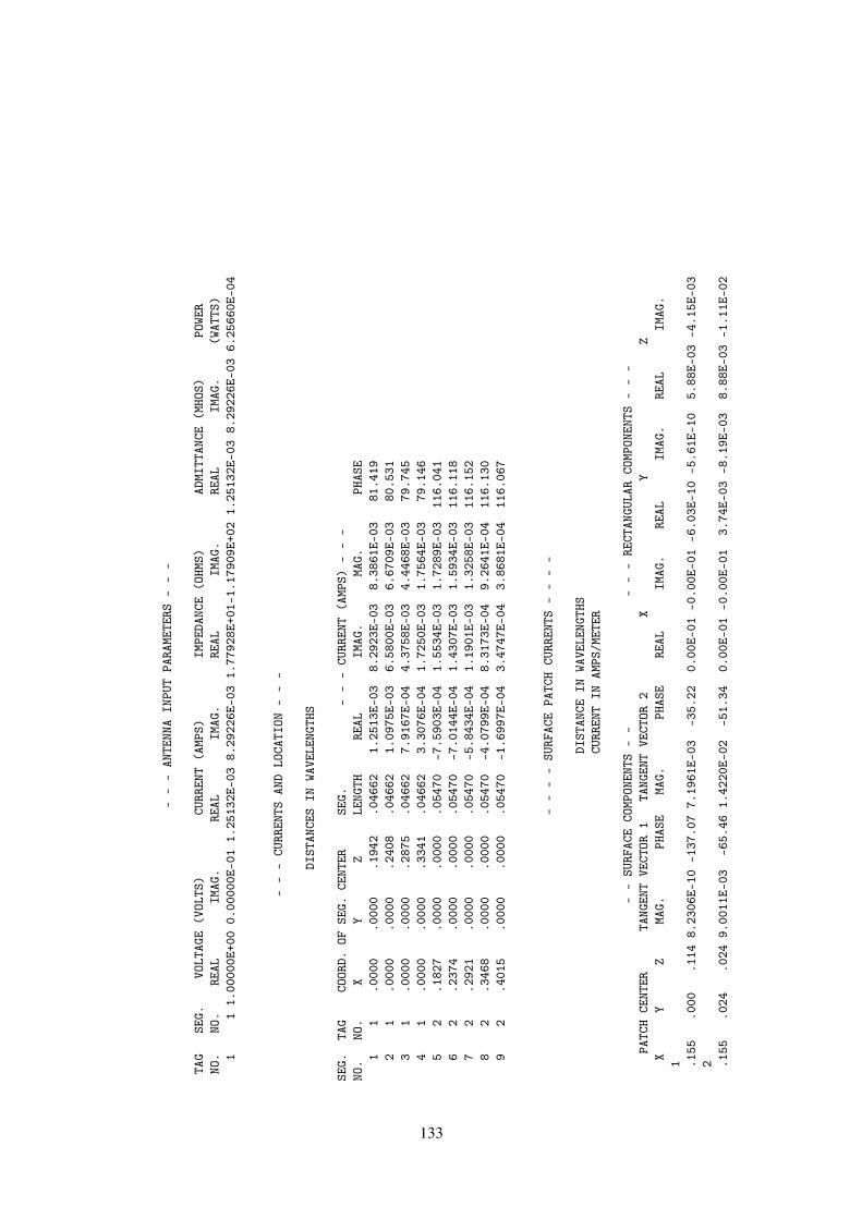
--
-AN
TENN
AIN
PUT
PARA
METE
RS-
--
TAG
SEG.
VOLT
AGE
(VOL
TS)
CURR
ENT
(AMP
S)IM
PEDA
NCE
(OHM
S)AD
MITT
ANCE
(MHO
S)PO
WER
NO.
NO.
REAL
IMAG
.RE
ALIM
AG.
REAL
IMAG
.RE
ALIM
AG.
(WAT
TS)
11
1.00
000E
+00
0.00
000E
-01
1.25
132E
-03
8.29
226E
-03
1.77
928E
+01-
1.17
909E
+02
1.25
132E
-03
8.29
226E
-03
6.25
660E
-04
--
-CU
RREN
TSAN
DLO
CATI
ON-
--
DIST
ANCE
SIN
WAVE
LENG
THS
SEG.
TAG
COOR
D.OF
SEG.
CENT
ERSE
G.-
--
CURR
ENT
(AMP
S)-
--
NO.
NO.
XY
ZLE
NGTH
REAL
IMAG
.MA
G.PH
ASE
11
.000
0.0
000
.194
2.0
4662
1.25
13E-
038.
2923
E-03
8.38
61E-
0381
.419
21
.000
0.0
000
.240
8.0
4662
1.09
75E-
036.
5800
E-03
6.67
09E-
0380
.531
31
.000
0.0
000
.287
5.0
4662
7.91
67E-
044.
3758
E-03
4.44
68E-
0379
.745
41
.000
0.0
000
.334
1.0
4662
3.30
76E-
041.
7250
E-03
1.75
64E-
0379
.146
52
.182
7.0
000
.000
0.0
5470
-7.5
903E
-04
1.55
34E-
031.
7289
E-03
116.
041
62
.237
4.0
000
.000
0.0
5470
-7.0
144E
-04
1.43
07E-
031.
5934
E-03
116.
118
72
.292
1.0
000
.000
0.0
5470
-5.8
434E
-04
1.19
01E-
031.
3258
E-03
116.
152
82
.346
8.0
000
.000
0.0
5470
-4.0
799E
-04
8.31
73E-
049.
2641
E-04
116.
130
92
.401
5.0
000
.000
0.0
5470
-1.6
997E
-04
3.47
47E-
043.
8681
E-04
116.
067
--
--
SURF
ACE
PATC
HCU
RREN
TS-
--
-
DIST
ANCE
INWA
VELE
NGTH
SCU
RREN
TIN
AMPS
/MET
ER
--
SURF
ACE
COMP
ONEN
TS-
--
--
RECT
ANGU
LAR
COMP
ONEN
TS-
--
PATC
HCE
NTER
TANG
ENT
VECT
OR1
TANG
ENT
VECT
OR2
XY
ZX
YZ
MAG.
PHAS
EMA
G.PH
ASE
REAL
IMAG
.RE
ALIM
AG.
REAL
IMAG
.1 .1
55.0
00.1
148.
2306
E-10
-137
.07
7.19
61E-
03-3
5.22
0.00
E-01
-0.0
0E-0
1-6
.03E
-10
-5.6
1E-1
05.
88E-
03-4
.15E
-03
2 .155
.024
.024
9.00
11E-
03-6
5.46
1.42
20E-
02-5
1.34
0.00
E-01
-0.0
0E-0
13.
74E-
03-8
.19E
-03
8.88
E-03
-1.1
1E-0
2
133

3 .155
-.02
4.0
249.
0011
E-03
114.
541.
4220
E-02
-51.
340.
00E-
010.
00E-
01-3
.74E
-03
8.19
E-03
8.88
E-03
-1.1
1E-0
24 .1
55-.
024
-.02
49.
0080
E-03
114.
495.
0962
E-03
84.3
10.
00E-
010.
00E-
01-3
.73E
-03
8.20
E-03
5.06
E-04
5.07
E-03
5 .155
.024
-.02
49.
0079
E-03
-65.
515.
0962
E-03
84.3
10.
00E-
010.
00E-
013.
73E-
03-8
.20E
-03
5.06
E-04
5.07
E-03
6 .155
.000
-.11
46.
8882
E-10
118.
131.
5973
E-03
12.5
30.
00E-
010.
00E-
01-3
.25E
-10
6.07
E-10
1.56
E-03
3.46
E-04
7 .135
.078
.114
1.87
92E-
03-9
4.87
5.54
28E-
03-1
1.30
7.97
E-05
9.36
E-04
-1.3
8E-0
4-1
.62E
-03
5.44
E-03
-1.0
9E-0
38 .1
35.0
78.0
003.
9148
E-03
-75.
495.
3139
E-03
-33.
00-4
.90E
-04
1.89
E-03
8.49
E-04
-3.2
8E-0
34.
46E-
03-2
.89E
-03
9 .135
.078
-.11
41.
8133
E-03
-94.
602.
9184
E-03
-33.
427.
28E-
059.
04E-
04-1
.26E
-04
-1.5
7E-0
32.
44E-
03-1
.61E
-03
10 .107
.000
.171
1.36
91E-
02-1
04.8
11.
1337
E-09
-154
.91
-3.5
0E-0
3-1
.32E
-02
-1.0
3E-0
9-4
.81E
-10
0.00
E-01
0.00
E-01
11 .107
.000
-.17
11.
5187
E-03
-10.
621.
0574
E-09
-70.
171.
49E-
03-2
.80E
-04
-3.5
9E-1
09.
95E-
100.
00E-
010.
00E-
0112 .0
78.1
35.1
141.
6705
E-03
-129
.81
4.74
14E-
03-8
.86
9.26
E-04
1.11
E-03
-5.3
5E-0
4-6
.42E
-04
4.68
E-03
-7.3
0E-0
413 .0
78.1
35.0
001.
6294
E-03
-112
.84
5.36
99E-
03-3
3.12
5.48
E-04
1.30
E-03
-3.1
6E-0
4-7
.51E
-04
4.50
E-03
-2.9
3E-0
314 .0
78.1
35-.
114
1.72
26E-
03-1
28.5
84.
1506
E-03
-48.
629.
30E-
041.
17E-
03-5
.37E
-04
-6.7
3E-0
42.
74E-
03-3
.11E
-03
15 0.00
0.1
55.1
141.
4450
E-03
-160
.34
5.32
32E-
0311
.87
1.36
E-03
4.86
E-04
4.06
E-11
1.45
E-11
5.21
E-03
1.09
E-03
16 0.00
0.1
55.0
001.
2074
E-03
-155
.49
5.36
90E-
03-3
2.95
1.10
E-03
5.01
E-04
3.27
E-11
1.49
E-11
4.51
E-03
-2.9
2E-0
317 0.
000
.155
-.11
41.
4416
E-03
-160
.26
4.60
31E-
03-5
4.61
1.36
E-03
4.87
E-04
4.04
E-11
1.45
E-11
2.67
E-03
-3.7
5E-0
318 .0
54.0
93.1
711.
4845
E-02
-105
.23
1.60
76E-
03-1
45.6
4-8
.01E
-04
-6.3
8E-0
3-4
.04E
-03
-1.2
9E-0
20.
00E-
010.
00E-
0119 .0
54.0
93-.
171
1.75
48E-
03-5
0.91
1.60
63E-
0335
.02
1.69
E-03
1.17
E-04
3.00
E-04
-1.6
4E-0
30.
00E-
01-0
.00E
-01
20 -.07
8.1
35.1
141.
3169
E-03
-178
.68
5.04
09E-
03-2
.54
1.14
E-03
2.63
E-05
6.58
E-04
1.52
E-05
5.04
E-03
-2.2
4E-0
421 -.
078
.135
.000
9.94
95E-
0417
8.63
5.37
44E-
03-3
3.13
8.61
E-04
-2.0
5E-0
54.
97E-
04-1
.19E
-05
4.50
E-03
-2.9
4E-0
3
134

22 -.07
8.1
35-.
114
1.30
19E-
0317
8.62
4.33
71E-
03-5
6.62
1.13
E-03
-2.7
2E-0
56.
51E-
04-1
.57E
-05
2.39
E-03
-3.6
2E-0
323 -.
135
.078
.114
7.05
36E-
0416
1.19
5.74
72E-
039.
563.
34E-
04-1
.14E
-04
5.78
E-04
-1.9
7E-0
45.
67E-
039.
54E-
0424 -.
135
.078
.000
5.80
00E-
0416
5.30
5.37
16E-
03-3
3.03
2.81
E-04
-7.3
6E-0
54.
86E-
04-1
.27E
-04
4.50
E-03
-2.9
3E-0
325 -.
135
.078
-.11
46.
9540
E-04
166.
604.
2602
E-03
-58.
973.
38E-
04-8
.06E
-05
5.86
E-04
-1.4
0E-0
42.
20E-
03-3
.65E
-03
26 -.05
4.0
93.1
711.
5570
E-02
-109
.02
1.41
43E-
03-1
76.6
93.
76E-
037.
43E-
03-3
.69E
-03
-1.2
7E-0
20.
00E-
010.
00E-
0127 -.
054
.093
-.17
11.
7609
E-03
-92.
001.
4055
E-03
2.99
1.25
E-03
9.43
E-04
6.48
E-04
-1.4
9E-0
3-0
.00E
-01
-0.0
0E-0
128 -.
155
0.00
0.1
141.
0996
E-09
43.3
45.
2708
E-03
-3.8
24.
77E-
174.
50E-
17-8
.00E
-10
-7.5
5E-1
05.
26E-
03-3
.51E
-04
29 -.15
50.
000
.000
6.96
14E-
10-7
6.06
5.37
01E-
03-3
3.05
1.00
E-17
-4.0
3E-1
7-1
.68E
-10
6.76
E-10
4.50
E-03
-2.9
3E-0
330 -.
155
0.00
0-.
114
1.01
66E-
09-5
7.35
4.07
53E-
03-5
7.88
3.27
E-17
-5.1
0E-1
7-5
.48E
-10
8.56
E-10
2.17
E-03
-3.4
5E-0
331 -.
135
-.07
8.1
147.
0536
E-04
-18.
815.
7472
E-03
9.56
3.34
E-04
-1.1
4E-0
4-5
.78E
-04
1.97
E-04
5.67
E-03
9.54
E-04
32 -.13
5-.
078
.000
5.80
00E-
04-1
4.70
5.37
16E-
03-3
3.03
2.81
E-04
-7.3
6E-0
5-4
.86E
-04
1.27
E-04
4.50
E-03
-2.9
3E-0
333 -.
135
-.07
8-.
114
6.95
41E-
04-1
3.40
4.26
02E-
03-5
8.97
3.38
E-04
-8.0
6E-0
5-5
.86E
-04
1.40
E-04
2.20
E-03
-3.6
5E-0
334 -.
107
0.00
0.1
711.
5557
E-02
-111
.31
1.75
09E-
0955
.73
5.65
E-03
1.45
E-02
-6.4
9E-1
0-5
.83E
-10
-0.0
0E-0
1-0
.00E
-01
35 -.10
70.
000
-.17
11.
6720
E-03
-112
.54
1.47
23E-
0913
8.28
6.41
E-04
1.54
E-03
-1.0
6E-0
91.
07E-
090.
00E-
01-0
.00E
-01
36 -.07
8-.
135
.114
1.31
69E-
031.
325.
0409
E-03
-2.5
41.
14E-
032.
63E-
05-6
.58E
-04
-1.5
2E-0
55.
04E-
03-2
.24E
-04
37 -.07
8-.
135
.000
9.94
95E-
04-1
.37
5.37
44E-
03-3
3.13
8.61
E-04
-2.0
5E-0
5-4
.97E
-04
1.19
E-05
4.50
E-03
-2.9
4E-0
338 -.
078
-.13
5-.
114
1.30
19E-
03-1
.38
4.33
71E-
03-5
6.62
1.13
E-03
-2.7
2E-0
5-6
.51E
-04
1.57
E-05
2.39
E-03
-3.6
2E-0
339 0.
000
-.15
5.1
141.
4450
E-03
19.6
65.
3232
E-03
11.8
71.
36E-
034.
86E-
041.
62E-
105.
79E-
115.
21E-
031.
09E-
0340 0.
000
-.15
5.0
001.
2074
E-03
24.5
15.
3690
E-03
-32.
951.
10E-
035.
01E-
041.
31E-
105.
97E-
114.
51E-
03-2
.92E
-03
135

41 0.00
0-.
155
-.11
41.
4416
E-03
19.7
44.
6031
E-03
-54.
611.
36E-
034.
87E-
041.
62E-
105.
80E-
112.
67E-
03-3
.75E
-03
42 -.05
4-.
093
.171
1.55
69E-
02-1
09.0
21.
4143
E-03
3.31
3.76
E-03
7.43
E-03
3.69
E-03
1.27
E-02
-0.0
0E-0
1-0
.00E
-01
43 -.05
4-.
093
-.17
11.
7609
E-03
-92.
001.
4055
E-03
-177
.01
1.25
E-03
9.43
E-04
-6.4
8E-0
41.
49E-
030.
00E-
010.
00E-
0144 .0
78-.
135
.114
1.67
05E-
0350
.19
4.74
14E-
03-8
.86
9.26
E-04
1.11
E-03
5.35
E-04
6.42
E-04
4.68
E-03
-7.3
0E-0
445 .0
78-.
135
.000
1.62
94E-
0367
.16
5.36
99E-
03-3
3.12
5.48
E-04
1.30
E-03
3.16
E-04
7.51
E-04
4.50
E-03
-2.9
3E-0
346 .0
78-.
135
-.11
41.
7226
E-03
51.4
24.
1506
E-03
-48.
629.
30E-
041.
17E-
035.
37E-
046.
73E-
042.
74E-
03-3
.11E
-03
47 .135
-.07
8.1
141.
8792
E-03
85.1
35.
5428
E-03
-11.
307.
97E-
059.
36E-
041.
38E-
041.
62E-
035.
44E-
03-1
.09E
-03
48 .135
-.07
8.0
003.
9148
E-03
104.
515.
3139
E-03
-33.
00-4
.90E
-04
1.89
E-03
-8.4
9E-0
43.
28E-
034.
46E-
03-2
.89E
-03
49 .135
-.07
8-.
114
1.81
33E-
0385
.40
2.91
84E-
03-3
3.42
7.28
E-05
9.04
E-04
1.26
E-04
1.57
E-03
2.44
E-03
-1.6
1E-0
350 .0
54-.
093
.171
1.48
45E-
02-1
05.2
31.
6076
E-03
34.3
6-8
.01E
-04
-6.3
8E-0
34.
04E-
031.
29E-
02-0
.00E
-01
-0.0
0E-0
151 .0
54-.
093
-.17
11.
7548
E-03
-50.
911.
6063
E-03
-144
.98
1.69
E-03
1.17
E-04
-3.0
0E-0
41.
64E-
030.
00E-
010.
00E-
0152 .0
26.0
26.1
713.
7707
E-02
-97.
613.
8523
E-02
-99.
40-4
.99E
-03
-3.7
4E-0
2-6
.29E
-03
-3.8
0E-0
20.
00E-
010.
00E-
0153 -.
026
.026
.171
3.89
71E-
0278
.78
3.84
96E-
02-9
9.34
7.58
E-03
3.82
E-02
-6.2
5E-0
3-3
.80E
-02
0.00
E-01
0.00
E-01
54 -.02
6-.
026
.171
3.89
71E-
0278
.78
3.84
96E-
0280
.66
7.58
E-03
3.82
E-02
6.25
E-03
3.80
E-02
0.00
E-01
0.00
E-01
55 .026
-.02
6.1
713.
7707
E-02
-97.
613.
8523
E-02
80.6
0-4
.99E
-03
-3.7
4E-0
26.
29E-
033.
80E-
02-0
.00E
-01
-0.0
0E-0
156 .0
00.0
00-.
171
1.35
23E-
0318
.00
1.29
76E-
09-5
8.81
1.29
E-03
4.18
E-04
-6.7
2E-1
01.
11E-
090.
00E-
010.
00E-
01
--
-PO
WER
BUDG
ET-
--
INPU
TPO
WER
=6.
2566
E-04
WATT
SRA
DIAT
EDPO
WER=
6.25
66E-
04WA
TTS
136
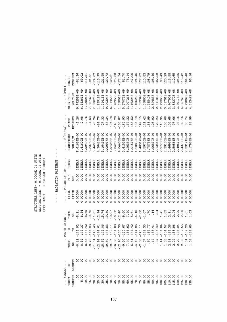
STRU
CTUR
ELO
SS=
0.00
00E-
01WA
TTS
NETW
ORK
LOSS
=0.
0000
E-01
WATT
SEF
FICI
ENCY
=10
0.00
PERC
ENT
--
-RA
DIAT
ION
PATT
ERNS
--
-
--
ANGL
ES-
--
POWE
RGA
INS
--
--
POLA
RIZA
TION
--
--
--
E(TH
ETA)
--
--
--
E(PH
I)-
--
THET
APH
IVE
RT.
HOR.
TOTA
LAX
IAL
TILT
SENS
EMA
GNIT
UDE
PHAS
EMA
GNIT
UDE
PHAS
EDE
GREE
SDE
GREE
SDB
DBDB
RATI
ODE
G.VO
LTS/
MDE
GREE
SVO
LTS/
MDE
GREE
S.0
0.0
0-8
.11
-145
.92
-8.1
10.
0000
00.
00LI
NEAR
7.61
669E
-02
-2.2
69.
7925
9E-0
9-8
1.36
5.00
.00
-8.3
4-1
49.3
7-8
.34
0.00
000
0.00
LINE
AR7.
4160
2E-0
2-2
.08
6.58
361E
-09
-69.
0210
.00
.00
-8.8
5-1
45.4
2-8
.85
0.00
000
0.00
LINE
AR6.
9949
9E-0
2-2
.76
1.03
806E
-08
-111
.51
15.0
0.0
0-9
.70
-147
.83
-9.7
00.
0000
00.
00LI
NEAR
6.33
760E
-02
-4.6
37.
8673
2E-0
9-9
1.91
20.0
0.0
0-1
1.01
-148
.43
-11.
010.
0000
00.
00LI
NEAR
5.44
956E
-02
-8.2
47.
3362
0E-0
9-1
74.0
225
.00
.00
-12.
94-1
44.6
1-1
2.94
0.00
000
0.00
LINE
AR4.
3641
6E-0
2-1
4.78
1.13
919E
-08
-113
.95
30.0
0.0
0-1
5.74
-144
.06
-15.
740.
0000
00.
00LI
NEAR
3.16
466E
-02
-27.
331.
2141
8E-0
8-1
21.5
835
.00
.00
-19.
30-1
45.8
3-1
9.30
0.00
000
0.00
LINE
AR2.
0997
7E-0
2-5
5.34
9.90
304E
-09
-129
.72
40.0
0.0
0-1
9.97
-150
.11
-19.
970.
0000
00.
00LI
NEAR
1.94
288E
-02
-107
.78
6.04
458E
-09
-138
.61
45.0
0.0
0-1
6.08
-161
.08
-16.
080.
0000
00.
00LI
NEAR
3.04
205E
-02
-145
.28
1.70
958E
-09
125.
0050
.00
.00
-12.
40-1
60.3
6-1
2.40
0.00
000
0.00
LINE
AR4.
6448
8E-0
2-1
63.8
71.
8580
1E-0
9-1
72.3
455
.00
.00
-9.6
0-1
50.6
7-9
.60
0.00
000
0.00
LINE
AR6.
4155
9E-0
2-1
75.9
35.
6707
5E-0
981
.70
60.0
0.0
0-7
.40
-155
.62
-7.4
00.
0000
00.
00LI
NEAR
8.26
330E
-02
174.
323.
2072
1E-0
975
.14
65.0
0.0
0-5
.61
-144
.42
-5.6
10.
0000
00.
00LI
NEAR
1.01
577E
-01
165.
521.
1639
4E-0
814
7.06
70.0
0.0
0-4
.10
-144
.86
-4.1
00.
0000
00.
00LI
NEAR
1.20
850E
-01
157.
181.
1062
5E-0
812
4.46
75.0
0.0
0-2
.80
-143
.11
-2.8
00.
0000
00.
00LI
NEAR
1.40
312E
-01
149.
151.
3533
4E-0
812
2.02
80.0
0.0
0-1
.67
-141
.35
-1.6
70.
0000
00.
00LI
NEAR
1.59
736E
-01
141.
421.
6586
0E-0
811
5.82
85.0
0.0
0-.
70-1
39.7
7-.
700.
0000
00.
00LI
NEAR
1.78
758E
-01
133.
991.
9884
0E-0
810
8.79
90.0
0.0
0.1
4-1
38.4
1.1
40.
0000
00.
00LI
NEAR
1.96
870E
-01
126.
922.
3248
3E-0
810
8.46
95.0
0.0
0.8
4-1
37.4
0.8
40.
0000
00.
00LI
NEAR
2.13
447E
-01
120.
232.
6118
5E-0
810
2.58
100.
00.0
01.
41-1
37.0
41.
410.
0000
00.
00LI
NEAR
2.27
788E
-01
113.
952.
7236
3E-0
898
.49
105.
00.0
01.
83-1
34.5
71.
830.
0000
00.
00LI
NEAR
2.39
180E
-01
108.
083.
6176
1E-0
812
0.29
110.
00.0
02.
11-1
34.3
62.
110.
0000
00.
00LI
NEAR
2.46
958E
-01
102.
653.
7079
0E-0
811
3.58
115.
00.0
02.
24-1
33.9
62.
240.
0000
00.
00LI
NEAR
2.50
561E
-01
97.6
63.
8827
2E-0
811
2.65
120.
00.0
02.
20-1
33.9
42.
200.
0000
00.
00LI
NEAR
2.49
579E
-01
93.1
53.
8917
8E-0
810
4.56
125.
00.0
02.
00-1
32.5
52.
000.
0000
00.
00LI
NEAR
2.43
788E
-01
89.1
64.
5676
9E-0
811
5.42
130.
00.0
01.
61-1
32.2
61.
610.
0000
00.
00LI
NEAR
2.33
171E
-01
85.7
44.
7206
2E-0
810
4.46
135.
00.0
01.
02-1
32.6
51.
020.
0000
00.
00LI
NEAR
2.17
933E
-01
82.9
94.
5124
7E-0
896
.16
137
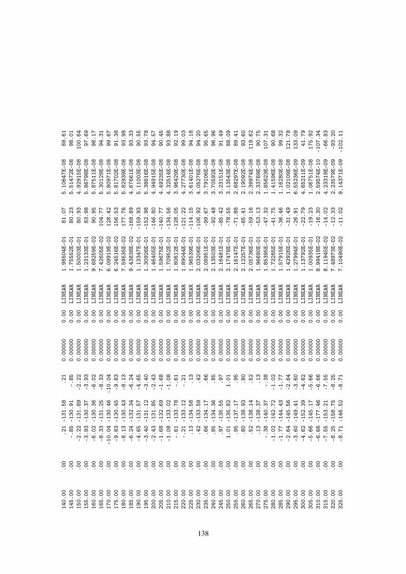
140.
00.0
0.2
1-1
31.5
8.2
10.
0000
00.
00LI
NEAR
1.98
504E
-01
81.0
75.
1064
7E-0
889
.61
145.
00.0
0-.
85-1
30.9
1-.
850.
0000
00.
00LI
NEAR
1.75
552E
-01
80.2
35.
5147
2E-0
898
.01
150.
00.0
0-2
.22
-131
.89
-2.2
20.
0000
00.
00LI
NEAR
1.50
003E
-01
80.9
34.
9291
5E-0
810
0.64
155.
00.0
0-3
.93
-130
.37
-3.9
30.
0000
00.
00LI
NEAR
1.23
133E
-01
83.9
85.
8679
8E-0
897
.69
160.
00.0
0-6
.02
-130
.36
-6.0
20.
0000
00.
00LI
NEAR
9.68
259E
-02
90.9
55.
8751
1E-0
898
.17
165.
00.0
0-8
.33
-131
.25
-8.3
30.
0000
00.
00LI
NEAR
7.42
605E
-02
104.
775.
3012
9E-0
894
.31
170.
00.0
0-1
0.04
-130
.46
-10.
040.
0000
00.
00LI
NEAR
6.09
919E
-02
128.
425.
8097
1E-0
899
.67
175.
00.0
0-9
.83
-130
.45
-9.8
30.
0000
00.
00LI
NEAR
6.24
516E
-02
156.
535.
8170
2E-0
891
.38
180.
00.0
0-8
.13
-130
.43
-8.1
30.
0000
00.
00LI
NEAR
7.59
535E
-02
177.
765.
8293
9E-0
893
.98
185.
00.0
0-6
.24
-132
.34
-6.2
40.
0000
00.
00LI
NEAR
9.43
838E
-02
-168
.89
4.67
661E
-08
93.3
319
0.00
.00
-4.6
5-1
31.5
7-4
.65
0.00
000
0.00
LINE
AR1.
1334
7E-0
1-1
59.9
35.
1100
3E-0
890
.55
195.
00.0
0-3
.40
-131
.12
-3.4
00.
0000
00.
00LI
NEAR
1.30
926E
-01
-152
.98
5.38
616E
-08
93.7
820
0.00
.00
-2.4
3-1
31.8
5-2
.43
0.00
000
0.00
LINE
AR1.
4640
5E-0
1-1
46.8
04.
9491
5E-0
894
.57
205.
00.0
0-1
.68
-132
.69
-1.6
80.
0000
00.
00LI
NEAR
1.59
675E
-01
-140
.77
4.49
235E
-08
90.4
521
0.00
.00
-1.0
8-1
33.0
2-1
.08
0.00
000
0.00
LINE
AR1.
7095
2E-0
1-1
34.5
64.
3251
4E-0
893
.88
215.
00.0
0-.
61-1
33.7
8-.
610.
0000
00.
00LI
NEAR
1.80
612E
-01
-128
.05
3.96
429E
-08
92.1
922
0.00
.00
-.21
-133
.12
-.21
0.00
000
0.00
LINE
AR1.
8904
4E-0
1-1
21.2
24.
2773
0E-0
899
.03
225.
00.0
0.1
3-1
34.5
8.1
30.
0000
00.
00LI
NEAR
1.96
539E
-01
-114
.15
3.61
401E
-08
94.1
823
0.00
.00
.42
-133
.59
.42
0.00
000
0.00
LINE
AR2.
0320
6E-0
1-1
06.9
24.
0527
6E-0
894
.20
235.
00.0
0.6
6-1
34.1
7.6
60.
0000
00.
00LI
NEAR
2.08
951E
-01
-99.
673.
7910
6E-0
895
.65
240.
00.0
0.8
5-1
34.3
6.8
50.
0000
00.
00LI
NEAR
2.13
503E
-01
-92.
483.
7059
2E-0
896
.96
245.
00.0
0.9
7-1
35.5
5.9
70.
0000
00.
00LI
NEAR
2.16
481E
-01
-85.
423.
2315
1E-0
891
.49
250.
00.0
01.
01-1
35.8
21.
010.
0000
00.
00LI
NEAR
2.17
478E
-01
-78.
553.
1354
3E-0
888
.09
255.
00.0
0.9
5-1
37.1
7.9
50.
0000
00.
00LI
NEAR
2.16
147E
-01
-71.
882.
6829
7E-0
889
.41
260.
00.0
0.8
0-1
38.9
3.8
00.
0000
00.
00LI
NEAR
2.12
257E
-01
-65.
412.
1909
2E-0
893
.60
265.
00.0
0.5
2-1
38.1
4.5
20.
0000
00.
00LI
NEAR
2.05
736E
-01
-59.
162.
3997
4E-0
811
9.62
270.
00.0
0.1
3-1
38.3
7.1
30.
0000
00.
00LI
NEAR
1.96
690E
-01
-53.
132.
3376
9E-0
890
.75
275.
00.0
0-.
38-1
40.3
7-.
380.
0000
00.
00LI
NEAR
1.85
395E
-01
-47.
321.
8562
3E-0
810
7.31
280.
00.0
0-1
.02
-142
.72
-1.0
20.
0000
00.
00LI
NEAR
1.72
285E
-01
-41.
751.
4159
6E-0
890
.68
285.
00.0
0-1
.77
-144
.43
-1.7
70.
0000
00.
00LI
NEAR
1.57
915E
-01
-36.
461.
1628
0E-0
899
.32
290.
00.0
0-2
.64
-145
.56
-2.6
40.
0000
00.
00LI
NEAR
1.42
926E
-01
-31.
491.
0210
9E-0
812
1.78
295.
00.0
0-3
.60
-149
.41
-3.6
00.
0000
00.
00LI
NEAR
1.27
994E
-01
-26.
916.
5523
6E-0
913
3.09
300.
00.0
0-4
.62
-152
.39
-4.6
20.
0000
00.
00LI
NEAR
1.13
792E
-01
-22.
794.
6521
1E-0
941
.79
305.
00.0
0-5
.66
-145
.17
-5.6
60.
0000
00.
00LI
NEAR
1.00
935E
-01
-19.
231.
0675
1E-0
817
5.92
310.
00.0
0-6
.66
-177
.46
-6.6
60.
0000
00.
00LI
NEAR
8.99
418E
-02
-16.
302.
5957
4E-1
0-1
07.3
431
5.00
.00
-7.5
5-1
53.2
1-7
.55
0.00
000
0.00
LINE
AR8.
1194
5E-0
2-1
4.02
4.23
319E
-09
-66.
8332
0.00
.00
-8.2
5-1
58.7
5-8
.25
0.00
000
0.00
LINE
AR7.
4897
3E-0
2-1
2.33
2.23
579E
-09
-93.
2032
5.00
.00
-8.7
1-1
46.5
2-8
.71
0.00
000
0.00
LINE
AR7.
1049
0E-0
2-1
1.02
9.14
371E
-09
-102
.11
138
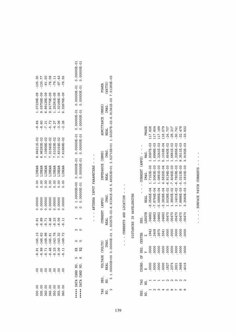
330.
00.0
0-8
.91
-145
.13
-8.9
10.
0000
00.
00LI
NEAR
6.94
311E
-02
-9.8
41.
0723
9E-0
8-1
05.3
033
5.00
.00
-8.8
9-1
46.6
2-8
.89
0.00
000
0.00
LINE
AR6.
9629
2E-0
2-8
.60
9.03
758E
-09
-120
.77
340.
00.0
0-8
.71
-148
.98
-8.7
10.
0000
00.
00LI
NEAR
7.10
808E
-02
-7.2
16.
8912
8E-0
9-6
1.50
345.
00.0
0-8
.46
-145
.81
-8.4
60.
0000
00.
00LI
NEAR
7.31
340E
-02
-5.7
29.
9177
9E-0
9-7
6.09
350.
00.0
0-8
.23
-143
.78
-8.2
30.
0000
00.
00LI
NEAR
7.51
023E
-02
-4.2
71.
2529
1E-0
8-7
9.11
355.
00.0
0-8
.09
-143
.32
-8.0
90.
0000
00.
00LI
NEAR
7.63
154E
-02
-3.0
61.
3216
8E-0
8-8
7.43
360.
00.0
0-8
.11
-149
.72
-8.1
10.
0000
00.
00LI
NEAR
7.61
669E
-02
-2.2
66.
3267
6E-0
9-7
6.55
****
*DA
TACA
RDNO
.5
EX0
21
01.
0000
0E+0
00.
0000
0E-0
10.
0000
0E-0
10.
0000
0E-0
10.
0000
0E-0
10.
0000
0E-0
1**
***
DATA
CARD
NO.
6XQ
00
00
0.00
000E
-01
0.00
000E
-01
0.00
000E
-01
0.00
000E
-01
0.00
000E
-01
0.00
000E
-01
--
-AN
TENN
AIN
PUT
PARA
METE
RS-
--
TAG
SEG.
VOLT
AGE
(VOL
TS)
CURR
ENT
(AMP
S)IM
PEDA
NCE
(OHM
S)AD
MITT
ANCE
(MHO
S)PO
WER
NO.
NO.
REAL
IMAG
.RE
ALIM
AG.
REAL
IMAG
.RE
ALIM
AG.
(WAT
TS)
25
1.00
000E
+00
0.00
000E
-01
1.50
257E
-02-
6.91
341E
-03
5.49
253E
+01
2.52
715E
+01
1.50
257E
-02-
6.91
341E
-03
7.51
283E
-03
--
-CU
RREN
TSAN
DLO
CATI
ON-
--
DIST
ANCE
SIN
WAVE
LENG
THS
SEG.
TAG
COOR
D.OF
SEG.
CENT
ERSE
G.-
--
CURR
ENT
(AMP
S)-
--
NO.
NO.
XY
ZLE
NGTH
REAL
IMAG
.MA
G.PH
ASE
11
.000
0.0
000
.194
2.0
4662
-9.0
545E
-04
1.71
53E-
031.
9397
E-03
117.
828
21
.000
0.0
000
.240
8.0
4662
-7.8
764E
-04
1.50
63E-
031.
6998
E-03
117.
604
31
.000
0.0
000
.287
5.0
4662
-5.5
895E
-04
1.08
91E-
031.
2241
E-03
117.
169
41
.000
0.0
000
.334
1.0
4662
-2.2
826E
-04
4.56
25E-
045.
1016
E-04
116.
579
52
.182
7.0
000
.000
0.0
5470
1.50
26E-
02-6
.913
4E-0
31.
6540
E-02
-24.
707
62
.237
4.0
000
.000
0.0
5470
1.38
00E-
02-7
.404
5E-0
31.
5661
E-02
-28.
217
72
.292
1.0
000
.000
0.0
5470
1.14
01E-
02-6
.780
3E-0
31.
3265
E-02
-30.
741
82
.346
8.0
000
.000
0.0
5470
7.88
86E-
03-5
.021
3E-0
39.
3511
E-03
-32.
478
92
.401
5.0
000
.000
0.0
5470
3.25
60E-
03-2
.181
5E-0
33.
9192
E-03
-33.
822
--
--
SURF
ACE
PATC
HCU
RREN
TS-
--
-
139

DIST
ANCE
INWA
VELE
NGTH
SCU
RREN
TIN
AMPS
/MET
ER
--
SURF
ACE
COMP
ONEN
TS-
--
--
RECT
ANGU
LAR
COMP
ONEN
TS-
--
PATC
HCE
NTER
TANG
ENT
VECT
OR1
TANG
ENT
VECT
OR2
XY
ZX
YZ
MAG.
PHAS
EMA
G.PH
ASE
REAL
IMAG
.RE
ALIM
AG.
REAL
IMAG
.1 .1
55.0
00.1
144.
9007
E-09
-74.
044.
0390
E-02
140.
220.
00E-
010.
00E-
011.
35E-
09-4
.71E
-09
-3.1
0E-0
22.
58E-
022 .1
55.0
24.0
248.
6314
E-02
153.
298.
8849
E-02
152.
99-0
.00E
-01
0.00
E-01
-7.7
1E-0
23.
88E-
02-7
.92E
-02
4.04
E-02
3 .155
-.02
4.0
248.
6314
E-02
-26.
718.
8849
E-02
152.
990.
00E-
010.
00E-
017.
71E-
02-3
.88E
-02
-7.9
2E-0
24.
04E-
024 .1
55-.
024
-.02
48.
6311
E-02
-26.
719.
1285
E-02
-26.
160.
00E-
01-0
.00E
-01
7.71
E-02
-3.8
8E-0
28.
19E-
02-4
.02E
-02
5 .155
.024
-.02
48.
6311
E-02
153.
299.
1285
E-02
-26.
160.
00E-
010.
00E-
01-7
.71E
-02
3.88
E-02
8.19
E-02
-4.0
2E-0
26 .1
55.0
00-.
114
3.90
29E-
09-8
2.46
4.18
13E-
02-3
7.70
0.00
E-01
-0.0
0E-0
15.
12E-
10-3
.87E
-09
3.31
E-02
-2.5
6E-0
27 .1
35.0
78.1
141.
7533
E-02
121.
832.
2201
E-02
129.
654.
62E-
03-7
.45E
-03
-8.0
1E-0
31.
29E-
02-1
.42E
-02
1.71
E-02
8 .135
.078
.000
3.76
40E-
0214
1.92
1.32
36E-
032.
351.
48E-
02-1
.16E
-02
-2.5
7E-0
22.
01E-
021.
32E-
035.
43E-
059 .1
35.0
78-.
114
1.75
16E-
0212
1.83
2.30
96E-
02-4
5.71
4.62
E-03
-7.4
4E-0
3-8
.00E
-03
1.29
E-02
1.61
E-02
-1.6
5E-0
210 .1
07.0
00.1
712.
0213
E-02
-85.
048.
2560
E-09
-33.
161.
75E-
03-2
.01E
-02
6.91
E-09
-4.5
2E-0
90.
00E-
010.
00E-
0111 .1
07.0
00-.
171
1.68
74E-
02-8
7.11
6.74
17E-
0912
5.50
8.52
E-04
-1.6
9E-0
23.
91E-
09-5
.49E
-09
0.00
E-01
-0.0
0E-0
112 .0
78.1
35.1
141.
6710
E-02
87.5
26.
2224
E-03
106.
04-6
.27E
-04
-1.4
5E-0
23.
62E-
048.
35E-
03-1
.72E
-03
5.98
E-03
13 .078
.135
.000
1.57
67E-
0210
3.50
1.33
27E-
032.
803.
19E-
03-1
.33E
-02
-1.8
4E-0
37.
67E-
031.
33E-
036.
52E-
0514 .0
78.1
35-.
114
1.66
53E-
0287
.44
6.81
17E-
03-5
6.50
-6.4
3E-0
4-1
.44E
-02
3.71
E-04
8.32
E-03
3.76
E-03
-5.6
8E-0
315 0.
000
.155
.114
1.39
65E-
0255
.64
1.79
90E-
0389
.81
-7.8
8E-0
3-1
.15E
-02
-2.3
5E-1
0-3
.44E
-10
5.87
E-06
1.80
E-03
16
140

0.00
0.1
55.0
001.
1670
E-02
60.4
81.
3310
E-03
3.41
-5.7
5E-0
3-1
.02E
-02
-1.7
1E-1
0-3
.03E
-10
1.33
E-03
7.92
E-05
17 0.00
0.1
55-.
114
1.39
51E-
0255
.62
2.28
07E-
03-3
1.00
-7.8
8E-0
3-1
.15E
-02
-2.3
5E-1
0-3
.43E
-10
1.95
E-03
-1.1
7E-0
318 .0
54.0
93.1
719.
5476
E-03
-98.
111.
5574
E-02
70.7
8-5
.11E
-03
-1.7
5E-0
21.
40E-
03-8
.33E
-04
-0.0
0E-0
1-0
.00E
-01
19 .054
.093
-.17
16.
5730
E-03
-109
.90
1.55
42E-
02-1
09.2
4-5
.56E
-03
-1.5
8E-0
26.
24E-
041.
98E-
030.
00E-
010.
00E-
0120 -.
078
.135
.114
1.26
23E-
0234
.28
1.56
98E-
0317
9.32
-9.0
3E-0
3-6
.16E
-03
-5.2
2E-0
3-3
.55E
-03
-1.5
7E-0
31.
86E-
0521 -.
078
.135
.000
9.61
62E-
0334
.25
1.33
72E-
033.
28-6
.88E
-03
-4.6
9E-0
3-3
.97E
-03
-2.7
1E-0
31.
33E-
037.
65E-
0522 -.
078
.135
-.11
41.
2602
E-02
34.4
23.
6441
E-03
5.05
-9.0
0E-0
3-6
.17E
-03
-5.2
0E-0
3-3
.56E
-03
3.63
E-03
3.21
E-04
23 -.13
5.0
78.1
146.
7432
E-03
22.4
24.
2065
E-03
-179
.29
-3.1
2E-0
3-1
.29E
-03
-5.4
0E-0
3-2
.23E
-03
-4.2
1E-0
3-5
.18E
-05
24 -.13
5.0
78.0
005.
6060
E-03
21.5
61.
3441
E-03
3.20
-2.6
1E-0
3-1
.03E
-03
-4.5
2E-0
3-1
.78E
-03
1.34
E-03
7.51
E-05
25 -.13
5.0
78-.
114
6.73
04E-
0322
.44
6.24
15E-
036.
27-3
.11E
-03
-1.2
8E-0
3-5
.39E
-03
-2.2
2E-0
36.
20E-
036.
81E-
0426 -.
054
.093
.171
5.59
22E-
033.
151.
3634
E-02
38.7
4-1
.20E
-02
-7.5
4E-0
3-4
.82E
-04
-4.0
0E-0
30.
00E-
010.
00E-
0127 -.
054
.093
-.17
15.
8821
E-03
37.2
71.
3609
E-02
-141
.24
-1.1
5E-0
2-9
.16E
-03
-1.2
5E-0
3-1
.18E
-03
0.00
E-01
0.00
E-01
28 -.15
50.
000
.114
3.36
02E-
09-1
55.8
04.
2242
E-03
178.
48-1
.83E
-16
-8.2
1E-1
73.
06E-
091.
38E-
09-4
.22E
-03
1.12
E-04
29 -.15
50.
000
.000
4.22
38E-
0986
.14
1.34
71E-
033.
051.
70E-
172.
51E-
16-2
.84E
-10
-4.2
1E-0
91.
35E-
037.
17E-
0530 -.
155
0.00
0-.
114
3.19
06E-
0916
2.32
6.30
63E-
032.
13-1
.81E
-16
5.78
E-17
3.04
E-09
-9.6
9E-1
06.
30E-
032.
34E-
0431 -.
135
-.07
8.1
146.
7433
E-03
-157
.58
4.20
65E-
03-1
79.2
9-3
.12E
-03
-1.2
9E-0
35.
40E-
032.
23E-
03-4
.21E
-03
-5.1
8E-0
532 -.
135
-.07
8.0
005.
6060
E-03
-158
.44
1.34
41E-
033.
20-2
.61E
-03
-1.0
3E-0
34.
52E-
031.
78E-
031.
34E-
037.
51E-
0533 -.
135
-.07
8-.
114
6.73
04E-
03-1
57.5
66.
2415
E-03
6.27
-3.1
1E-0
3-1
.28E
-03
5.39
E-03
2.22
E-03
6.20
E-03
6.81
E-04
34 -.10
70.
000
.171
1.15
20E-
029.
482.
5895
E-09
-158
.89
-1.1
4E-0
2-1
.90E
-03
1.74
E-09
8.20
E-10
0.00
E-01
0.00
E-01
35
141
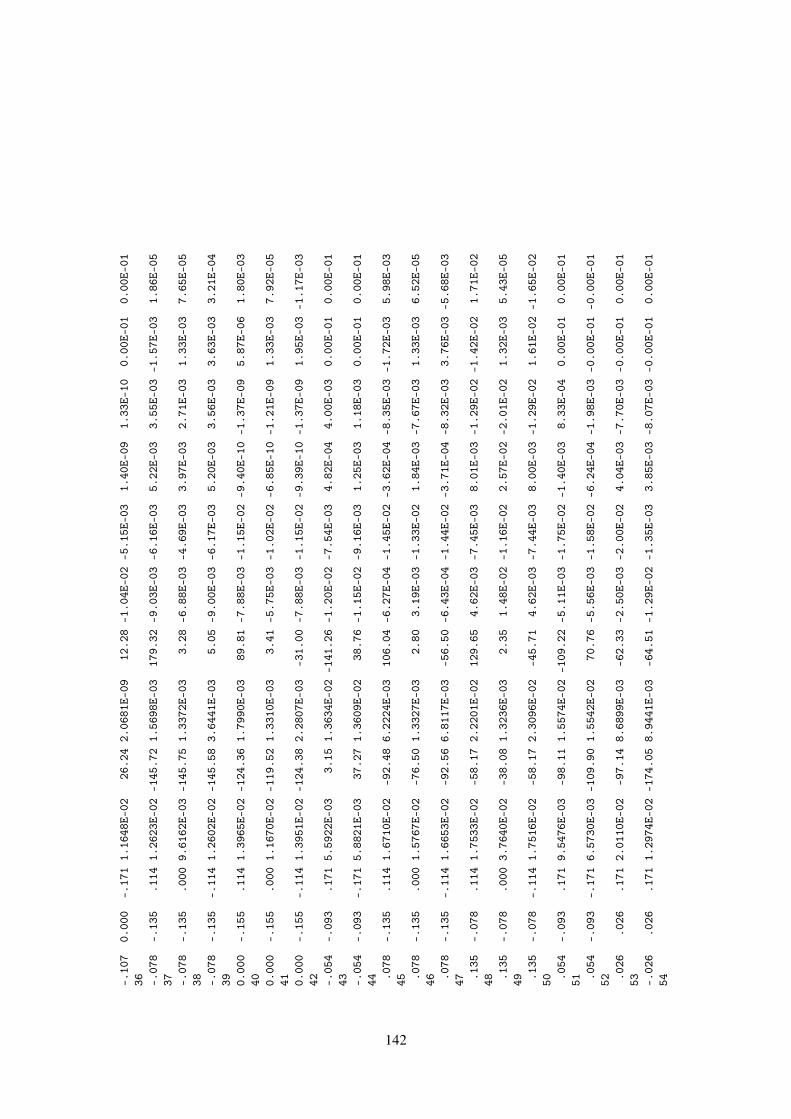
-.10
70.
000
-.17
11.
1648
E-02
26.2
42.
0681
E-09
12.2
8-1
.04E
-02
-5.1
5E-0
31.
40E-
091.
33E-
100.
00E-
010.
00E-
0136 -.
078
-.13
5.1
141.
2623
E-02
-145
.72
1.56
98E-
0317
9.32
-9.0
3E-0
3-6
.16E
-03
5.22
E-03
3.55
E-03
-1.5
7E-0
31.
86E-
0537 -.
078
-.13
5.0
009.
6162
E-03
-145
.75
1.33
72E-
033.
28-6
.88E
-03
-4.6
9E-0
33.
97E-
032.
71E-
031.
33E-
037.
65E-
0538 -.
078
-.13
5-.
114
1.26
02E-
02-1
45.5
83.
6441
E-03
5.05
-9.0
0E-0
3-6
.17E
-03
5.20
E-03
3.56
E-03
3.63
E-03
3.21
E-04
39 0.00
0-.
155
.114
1.39
65E-
02-1
24.3
61.
7990
E-03
89.8
1-7
.88E
-03
-1.1
5E-0
2-9
.40E
-10
-1.3
7E-0
95.
87E-
061.
80E-
0340 0.
000
-.15
5.0
001.
1670
E-02
-119
.52
1.33
10E-
033.
41-5
.75E
-03
-1.0
2E-0
2-6
.85E
-10
-1.2
1E-0
91.
33E-
037.
92E-
0541 0.
000
-.15
5-.
114
1.39
51E-
02-1
24.3
82.
2807
E-03
-31.
00-7
.88E
-03
-1.1
5E-0
2-9
.39E
-10
-1.3
7E-0
91.
95E-
03-1
.17E
-03
42 -.05
4-.
093
.171
5.59
22E-
033.
151.
3634
E-02
-141
.26
-1.2
0E-0
2-7
.54E
-03
4.82
E-04
4.00
E-03
0.00
E-01
0.00
E-01
43 -.05
4-.
093
-.17
15.
8821
E-03
37.2
71.
3609
E-02
38.7
6-1
.15E
-02
-9.1
6E-0
31.
25E-
031.
18E-
030.
00E-
010.
00E-
0144 .0
78-.
135
.114
1.67
10E-
02-9
2.48
6.22
24E-
0310
6.04
-6.2
7E-0
4-1
.45E
-02
-3.6
2E-0
4-8
.35E
-03
-1.7
2E-0
35.
98E-
0345 .0
78-.
135
.000
1.57
67E-
02-7
6.50
1.33
27E-
032.
803.
19E-
03-1
.33E
-02
1.84
E-03
-7.6
7E-0
31.
33E-
036.
52E-
0546 .0
78-.
135
-.11
41.
6653
E-02
-92.
566.
8117
E-03
-56.
50-6
.43E
-04
-1.4
4E-0
2-3
.71E
-04
-8.3
2E-0
33.
76E-
03-5
.68E
-03
47 .135
-.07
8.1
141.
7533
E-02
-58.
172.
2201
E-02
129.
654.
62E-
03-7
.45E
-03
8.01
E-03
-1.2
9E-0
2-1
.42E
-02
1.71
E-02
48 .135
-.07
8.0
003.
7640
E-02
-38.
081.
3236
E-03
2.35
1.48
E-02
-1.1
6E-0
22.
57E-
02-2
.01E
-02
1.32
E-03
5.43
E-05
49 .135
-.07
8-.
114
1.75
16E-
02-5
8.17
2.30
96E-
02-4
5.71
4.62
E-03
-7.4
4E-0
38.
00E-
03-1
.29E
-02
1.61
E-02
-1.6
5E-0
250 .0
54-.
093
.171
9.54
76E-
03-9
8.11
1.55
74E-
02-1
09.2
2-5
.11E
-03
-1.7
5E-0
2-1
.40E
-03
8.33
E-04
0.00
E-01
0.00
E-01
51 .054
-.09
3-.
171
6.57
30E-
03-1
09.9
01.
5542
E-02
70.7
6-5
.56E
-03
-1.5
8E-0
2-6
.24E
-04
-1.9
8E-0
3-0
.00E
-01
-0.0
0E-0
152 .0
26.0
26.1
712.
0110
E-02
-97.
148.
6899
E-03
-62.
33-2
.50E
-03
-2.0
0E-0
24.
04E-
03-7
.70E
-03
-0.0
0E-0
10.
00E-
0153 -.
026
.026
.171
1.29
74E-
02-1
74.0
58.
9441
E-03
-64.
51-1
.29E
-02
-1.3
5E-0
33.
85E-
03-8
.07E
-03
-0.0
0E-0
10.
00E-
0154
142
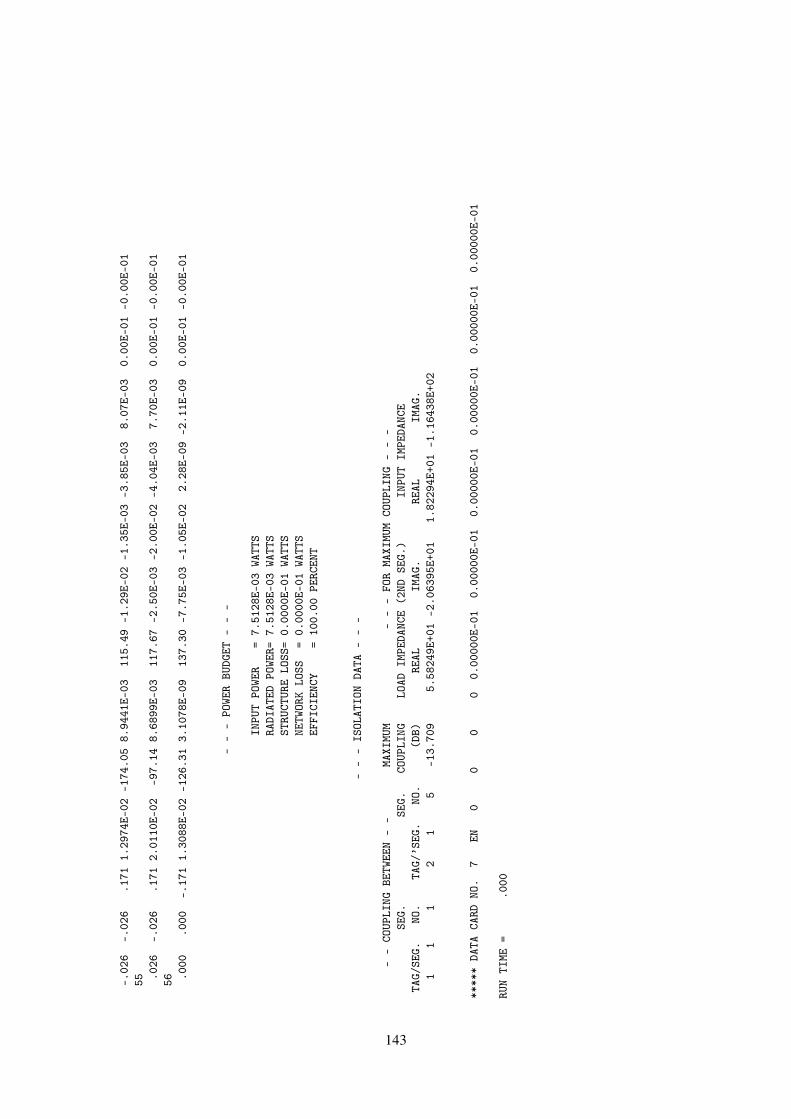
-.02
6-.
026
.171
1.29
74E-
02-1
74.0
58.
9441
E-03
115.
49-1
.29E
-02
-1.3
5E-0
3-3
.85E
-03
8.07
E-03
0.00
E-01
-0.0
0E-0
155 .0
26-.
026
.171
2.01
10E-
02-9
7.14
8.68
99E-
0311
7.67
-2.5
0E-0
3-2
.00E
-02
-4.0
4E-0
37.
70E-
030.
00E-
01-0
.00E
-01
56 .000
.000
-.17
11.
3088
E-02
-126
.31
3.10
78E-
0913
7.30
-7.7
5E-0
3-1
.05E
-02
2.28
E-09
-2.1
1E-0
90.
00E-
01-0
.00E
-01
--
-PO
WER
BUDG
ET-
--
INPU
TPO
WER
=7.
5128
E-03
WATT
SRA
DIAT
EDPO
WER=
7.51
28E-
03WA
TTS
STRU
CTUR
ELO
SS=
0.00
00E-
01WA
TTS
NETW
ORK
LOSS
=0.
0000
E-01
WATT
SEF
FICI
ENCY
=10
0.00
PERC
ENT
--
-IS
OLAT
ION
DATA
--
-
--
COUP
LING
BETW
EEN
--
MAXI
MUM
--
-FO
RMA
XIMU
MCO
UPLI
NG-
--
SEG.
SEG.
COUP
LING
LOAD
IMPE
DANC
E(2
NDSE
G.)
INPU
TIM
PEDA
NCE
TAG/
SEG.
NO.
TAG/
’SEG
.NO
.(D
B)RE
ALIM
AG.
REAL
IMAG
.1
11
21
5-1
3.70
95.
5824
9E+0
1-2
.063
95E+
011.
8229
4E+0
1-1
.164
38E+
02
****
*DA
TACA
RDNO
.7
EN0
00
00.
0000
0E-0
10.
0000
0E-0
10.
0000
0E-0
10.
0000
0E-0
10.
0000
0E-0
10.
0000
0E-0
1
RUN
TIME
=.0
00
143

4.2.7 Stick Model of an Aircraft in Free Space.
This examples demonstrates the use of NEC for scattering. The columns labeled "gain" are, in thiscase, scattering cross section in square wavelengths (σ /λ 2). Figure 23 illustrates a stick modelof an aircraft.
X
Y
Z
(0.0,0.0,0.0)(6.0,0.0,0.0)
(2.0,0.0,10.0) (2.0,11.3,0.0)
(2.0,−11.3,0.0)
(24.0,29.9,0.0)
(24.0,−29.9,0.0)
(44.0,0.0,0.0) (68.0,0.0,0.0)
φinc
~Einc
~k
Figure 23: Stick Model of Aircraft.
Input Card Deck :
CMSAMPLE PROBLEM FOR NECCESTICK MODEL OF AIRCRAFT - FREE SPACEGW 1, 1, 0., 0., 0., 6., 0., 0., 1.,GW 2 6 6. 0. 0. 44. 0. 0. 1.GW 3 4 44. 0. 0. 68. 0. 0. 1.GW 4 6 44. 0. 0. 24. 29.9 0. 1.GW 5 6 44. 0. 0. 24. -29.9 0. 1.GW 6 2 6. 0. 0. 2. 11.3 0. 1.GW 7 2 6. 0. 0. 2. -11.3 0. 1.GW 8 2 6. 0. 0. 2. 0. 10. 1.GEFR 0 1 0 0 3.EX 1 1 1 0 0.RP 0 1 1 1000 0. 0. 0.EX 1 1 1 0 90. 30. -90.RP 0 1 1 1000 90. 30.EN
Line-Printer Output :
144

****
****
****
****
****
****
****
****
****
NUME
RICA
LEL
ECTR
OMAG
NETI
CSCO
DE
****
****
****
****
****
****
****
****
****
--
--
COMM
ENTS
--
--
SAMP
LEPR
OBLE
MFO
RNE
CST
ICK
MODE
LOF
AIRC
RAFT
-FR
EESP
ACE
--
-ST
RUCT
URE
SPEC
IFIC
ATIO
N-
--
COOR
DINA
TES
MUST
BEIN
PUT
INME
TERS
ORBE
SCAL
EDTO
METE
RSBE
FORE
STRU
CTUR
EIN
PUT
ISEN
DED
WIRE
NO.
OFFI
RST
LAST
TAG
NO.
X1Y1
Z1X2
Y2Z2
RADI
USSE
G.SE
G.SE
G.NO
.1
.000
00.0
0000
.000
006.
0000
0.0
0000
.000
001.
0000
01
11
12
6.00
000
.000
00.0
0000
44.0
0000
.000
00.0
0000
1.00
000
62
72
344
.000
00.0
0000
.000
0068
.000
00.0
0000
.000
001.
0000
04
811
34
44.0
0000
.000
00.0
0000
24.0
0000
29.9
0000
.000
001.
0000
06
1217
45
44.0
0000
.000
00.0
0000
24.0
0000
-29.
9000
0.0
0000
1.00
000
618
235
66.
0000
0.0
0000
.000
002.
0000
011
.300
00.0
0000
1.00
000
224
256
76.
0000
0.0
0000
.000
002.
0000
0-1
1.30
000
.000
001.
0000
02
2627
78
6.00
000
.000
00.0
0000
2.00
000
.000
0010
.000
001.
0000
02
2829
8
TOTA
LSE
GMEN
TSUS
ED=
29NO
.SE
G.IN
ASY
MMET
RIC
CELL
=29
SYMM
ETRY
FLAG
=0
-MU
LTIP
LEWI
REJU
NCTI
ONS
-JU
NCTI
ONSE
GMEN
TS(-
FOR
END
1,+
FOR
END
2)1
1-2
-24
-26
-28
27
-8-1
2-1
8
145
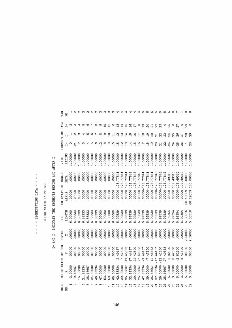
--
--
SEGM
ENTA
TION
DATA
--
--
COOR
DINA
TES
INME
TERS
I+AN
DI-
INDI
CATE
THE
SEGM
ENTS
BEFO
REAN
DAF
TER
I
SEG.
COOR
DINA
TES
OFSE
G.CE
NTER
SEG.
ORIE
NTAT
ION
ANGL
ESWI
RECO
NNEC
TION
DATA
TAG
NO.
XY
ZLE
NGTH
ALPH
ABE
TARA
DIUS
I-I
I+NO
.1
3.00
000
.000
00.0
0000
6.00
000
.000
00.0
0000
1.00
000
01
21
29.
1666
7.0
0000
.000
006.
3333
3.0
0000
.000
001.
0000
0-2
42
32
315
.500
00.0
0000
.000
006.
3333
3.0
0000
.000
001.
0000
02
34
24
21.8
3334
.000
00.0
0000
6.33
333
.000
00.0
0000
1.00
000
34
52
528
.166
67.0
0000
.000
006.
3333
3.0
0000
.000
001.
0000
04
56
26
34.5
0000
.000
00.0
0000
6.33
333
.000
00.0
0000
1.00
000
56
72
740
.833
34.0
0000
.000
006.
3333
3.0
0000
.000
001.
0000
06
78
28
47.0
0000
.000
00.0
0000
6.00
000
.000
00.0
0000
1.00
000
-12
89
39
53.0
0000
.000
00.0
0000
6.00
000
.000
00.0
0000
1.00
000
89
103
1059
.000
00.0
0000
.000
006.
0000
0.0
0000
.000
001.
0000
09
1011
311
65.0
0000
.000
00.0
0000
6.00
000
.000
00.0
0000
1.00
000
1011
03
1242
.333
342.
4916
7.0
0000
5.99
539
.000
0012
3.77
841
1.00
000
-18
1213
413
39.0
0000
7.47
500
.000
005.
9953
9.0
0000
123.
7784
11.
0000
012
1314
414
35.6
6667
12.4
5833
.000
005.
9953
9.0
0000
123.
7784
11.
0000
013
1415
415
32.3
3334
17.4
4167
.000
005.
9953
9.0
0000
123.
7784
31.
0000
014
1516
416
29.0
0000
22.4
2500
.000
005.
9953
9.0
0000
123.
7784
31.
0000
015
1617
417
25.6
6667
27.4
0833
.000
005.
9953
9.0
0000
123.
7784
31.
0000
016
170
418
42.3
3334
-2.4
9167
.000
005.
9953
9.0
0000
-123
.778
411.
0000
07
1819
519
39.0
0000
-7.4
7500
.000
005.
9953
9.0
0000
-123
.778
411.
0000
018
1920
520
35.6
6667
-12.
4583
3.0
0000
5.99
539
.000
00-1
23.7
7841
1.00
000
1920
215
2132
.333
34-1
7.44
167
.000
005.
9953
9.0
0000
-123
.778
431.
0000
020
2122
522
29.0
0000
-22.
4250
0.0
0000
5.99
539
.000
00-1
23.7
7843
1.00
000
2122
235
2325
.666
67-2
7.40
833
.000
005.
9953
9.0
0000
-123
.778
431.
0000
022
230
524
5.00
000
2.82
500
.000
005.
9935
4.0
0000
109.
4931
01.
0000
0-2
624
256
253.
0000
08.
4750
0.0
0000
5.99
354
.000
0010
9.49
310
1.00
000
2425
06
265.
0000
0-2
.825
00.0
0000
5.99
354
.000
00-1
09.4
9310
1.00
000
-28
2627
727
3.00
000
-8.4
7500
.000
005.
9935
4.0
0000
-109
.493
101.
0000
026
270
728
5.00
000
.000
002.
5000
05.
3851
668
.198
5918
0.00
000
1.00
000
128
298
293.
0000
0.0
0000
7.50
000
5.38
516
68.1
9859
180.
0000
01.
0000
028
290
8
146
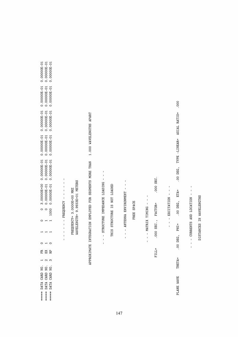
****
*DA
TACA
RDNO
.1
FR0
10
03.
0000
0E+0
00.
0000
0E-0
10.
0000
0E-0
10.
0000
0E-0
10.
0000
0E-0
10.
0000
0E-0
1**
***
DATA
CARD
NO.
2EX
11
10
0.00
000E
-01
0.00
000E
-01
0.00
000E
-01
0.00
000E
-01
0.00
000E
-01
0.00
000E
-01
****
*DA
TACA
RDNO
.3
RP0
11
1000
0.00
000E
-01
0.00
000E
-01
0.00
000E
-01
0.00
000E
-01
0.00
000E
-01
0.00
000E
-01
--
--
--
FREQ
UENC
Y-
--
--
-
FREQ
UENC
Y=3.
0000
E+00
MHZ
WAVE
LENG
TH=
9.99
33E+
01ME
TERS
APPR
OXIM
ATE
INTE
GRAT
ION
EMPL
OYED
FOR
SEGM
ENTS
MORE
THAN
1.00
0WA
VELE
NGTH
SAP
ART
--
-ST
RUCT
URE
IMPE
DANC
ELO
ADIN
G-
--
THIS
STRU
CTUR
EIS
NOT
LOAD
ED
--
-AN
TENN
AEN
VIRO
NMEN
T-
--
FREE
SPAC
E
--
-MA
TRIX
TIMI
NG-
--
FILL
=.0
00SE
C.,
FACT
OR=
.000
SEC.
--
-EX
CITA
TION
--
-
PLAN
EWA
VETH
ETA=
.00
DEG,
PHI=
.00
DEG,
ETA=
.00
DEG,
TYPE
-LIN
EAR=
AXIA
LRA
TIO=
.000
--
-CU
RREN
TSAN
DLO
CATI
ON-
--
DIST
ANCE
SIN
WAVE
LENG
THS
147

SEG.
TAG
COOR
D.OF
SEG.
CENT
ERSE
G.-
--
CURR
ENT
(AMP
S)-
--
NO.
NO.
XY
ZLE
NGTH
REAL
IMAG
.MA
G.PH
ASE
11
.030
0.0
000
.000
0.0
6004
1.49
98E-
034.
6949
E-03
4.92
86E-
0372
.284
22
.091
7.0
000
.000
0.0
6338
3.20
97E-
02-1
.702
3E-0
23.
6332
E-02
-27.
939
32
.155
1.0
000
.000
0.0
6338
3.79
67E-
02-3
.107
9E-0
24.
9065
E-02
-39.
303
42
.218
5.0
000
.000
0.0
6338
4.43
00E-
02-4
.946
1E-0
26.
6399
E-02
-48.
151
52
.281
9.0
000
.000
0.0
6338
4.93
42E-
02-6
.706
9E-0
28.
3264
E-02
-53.
658
62
.345
2.0
000
.000
0.0
6338
5.20
34E-
02-7
.982
9E-0
29.
5290
E-02
-56.
903
72
.408
6.0
000
.000
0.0
6338
5.16
37E-
02-8
.484
1E-0
29.
9319
E-02
-58.
674
83
.470
3.0
000
.000
0.0
6004
2.08
77E-
01-2
.089
5E-0
12.
9537
E-01
-45.
025
93
.530
4.0
000
.000
0.0
6004
1.78
43E-
01-1
.785
0E-0
12.
5239
E-01
-45.
010
103
.590
4.0
000
.000
0.0
6004
1.28
13E-
01-1
.275
2E-0
11.
8077
E-01
-44.
865
113
.650
4.0
000
.000
0.0
6004
5.92
05E-
02-5
.827
6E-0
28.
3074
E-02
-44.
547
124
.423
6.0
249
.000
0.0
5999
-8.3
232E
-02
6.61
92E-
021.
0634
E-01
141.
506
134
.390
3.0
748
.000
0.0
5999
-8.3
105E
-02
6.56
12E-
021.
0588
E-01
141.
709
144
.356
9.1
247
.000
0.0
5999
-7.6
168E
-02
5.87
25E-
029.
6178
E-02
142.
368
154
.323
5.1
745
.000
0.0
5999
-6.2
518E
-02
4.62
63E-
027.
7773
E-02
143.
499
164
.290
2.2
244
.000
0.0
5999
-4.3
490E
-02
3.02
12E-
025.
2954
E-02
145.
212
174
.256
8.2
743
.000
0.0
5999
-1.9
544E
-02
1.23
75E-
022.
3132
E-02
147.
657
185
.423
6-.
0249
.000
0.0
5999
-8.3
232E
-02
6.61
92E-
021.
0634
E-01
141.
506
195
.390
3-.
0748
.000
0.0
5999
-8.3
105E
-02
6.56
12E-
021.
0588
E-01
141.
709
205
.356
9-.
1247
.000
0.0
5999
-7.6
167E
-02
5.87
25E-
029.
6178
E-02
142.
368
215
.323
5-.
1745
.000
0.0
5999
-6.2
517E
-02
4.62
63E-
027.
7773
E-02
143.
499
225
.290
2-.
2244
.000
0.0
5999
-4.3
489E
-02
3.02
12E-
025.
2954
E-02
145.
212
235
.256
8-.
2743
.000
0.0
5999
-1.9
544E
-02
1.23
75E-
022.
3132
E-02
147.
657
246
.050
0.0
283
.000
0.0
5998
-1.0
118E
-02
5.23
57E-
031.
1393
E-02
152.
641
256
.030
0.0
848
.000
0.0
5998
-4.6
178E
-03
1.78
38E-
034.
9503
E-03
158.
879
267
.050
0-.
0283
.000
0.0
5998
-1.0
118E
-02
5.23
56E-
031.
1393
E-02
152.
641
277
.030
0-.
0848
.000
0.0
5998
-4.6
178E
-03
1.78
38E-
034.
9503
E-03
158.
879
288
.050
0.0
000
.025
0.0
5389
-5.2
942E
-03
5.34
53E-
037.
5234
E-03
134.
725
298
.030
0.0
000
.075
1.0
5389
-1.5
854E
-03
2.05
20E-
032.
5931
E-03
127.
691
--
-RA
DIAT
ION
PATT
ERNS
--
-
--
ANGL
ES-
--
POWE
RGA
INS
--
--
POLA
RIZA
TION
--
--
--
E(TH
ETA)
--
--
--
E(PH
I)-
--
THET
APH
IVE
RT.
HOR.
TOTA
LAX
IAL
TILT
SENS
EMA
GNIT
UDE
PHAS
EMA
GNIT
UDE
PHAS
E
148

DEGR
EES
DEGR
EES
DBDB
DBRA
TIO
DEG.
VOLT
S/M
DEGR
EES
VOLT
S/M
DEGR
EES
.00
.00
-2.9
8-1
34.6
4-2
.98
0.00
000
0.00
LINE
AR2.
0001
9E+0
1-1
33.9
75.
2279
7E-0
678
.18
****
*DA
TACA
RDNO
.4
EX1
11
09.
0000
0E+0
13.
0000
0E+0
1-9
.000
00E+
010.
0000
0E-0
10.
0000
0E-0
10.
0000
0E-0
1**
***
DATA
CARD
NO.
5RP
01
110
009.
0000
0E+0
13.
0000
0E+0
10.
0000
0E-0
10.
0000
0E-0
10.
0000
0E-0
10.
0000
0E-0
1
--
-EX
CITA
TION
--
-
PLAN
EWA
VETH
ETA=
90.0
0DE
G,PH
I=30
.00
DEG,
ETA=
-90.
00DE
G,TY
PE-L
INEA
R=AX
IAL
RATI
O=.0
00
--
-CU
RREN
TSAN
DLO
CATI
ON-
--
DIST
ANCE
SIN
WAVE
LENG
THS
SEG.
TAG
COOR
D.OF
SEG.
CENT
ERSE
G.-
--
CURR
ENT
(AMP
S)-
--
NO.
NO.
XY
ZLE
NGTH
REAL
IMAG
.MA
G.PH
ASE
11
.030
0.0
000
.000
0.0
6004
2.19
51E-
033.
6163
E-03
4.23
04E-
0358
.741
22
.091
7.0
000
.000
0.0
6338
6.54
48E-
033.
5229
E-03
7.43
27E-
0328
.292
32
.155
1.0
000
.000
0.0
6338
7.43
89E-
03-5
.772
3E-0
39.
4158
E-03
-37.
810
42
.218
5.0
000
.000
0.0
6338
9.88
56E-
03-1
.979
1E-0
22.
2123
E-02
-63.
458
52
.281
9.0
000
.000
0.0
6338
1.42
93E-
02-3
.527
1E-0
23.
8057
E-02
-67.
941
62
.345
2.0
000
.000
0.0
6338
2.00
95E-
02-4
.885
8E-0
25.
2829
E-02
-67.
643
72
.408
6.0
000
.000
0.0
6338
2.55
74E-
02-5
.769
9E-0
26.
3113
E-02
-66.
095
83
.470
3.0
000
.000
0.0
6004
-3.8
608E
-02
1.55
11E-
011.
5984
E-01
103.
977
93
.530
4.0
000
.000
0.0
6004
-2.7
542E
-02
1.31
76E-
011.
3460
E-01
101.
807
103
.590
4.0
000
.000
0.0
6004
-1.4
290E
-02
9.39
88E-
029.
5068
E-02
98.6
4511
3.6
504
.000
0.0
000
.060
04-3
.492
7E-0
34.
3257
E-02
4.33
98E-
0294
.616
124
.423
6.0
249
.000
0.0
5999
-2.3
663E
-02
-2.1
177E
-01
2.13
09E-
01-9
6.37
613
4.3
903
.074
8.0
000
.059
99-1
.640
3E-0
2-2
.048
8E-0
12.
0554
E-01
-94.
577
144
.356
9.1
247
.000
0.0
5999
-7.9
417E
-03
-1.8
318E
-01
1.83
35E-
01-9
2.48
315
4.3
235
.174
5.0
000
.059
99-3
.747
9E-0
4-1
.472
3E-0
11.
4723
E-01
-90.
146
164
.290
2.2
244
.000
0.0
5999
4.53
69E-
03-1
.003
2E-0
11.
0042
E-01
-87.
411
174
.256
8.2
743
.000
0.0
5999
4.53
11E-
03-4
.405
7E-0
24.
4289
E-02
-84.
128
185
.423
6-.
0249
.000
0.0
5999
9.46
28E-
02-8
.903
5E-0
39.
5046
E-02
-5.3
7519
5.3
903
-.07
48.0
000
.059
999.
3141
E-02
-9.9
663E
-03
9.36
73E-
02-6
.108
149
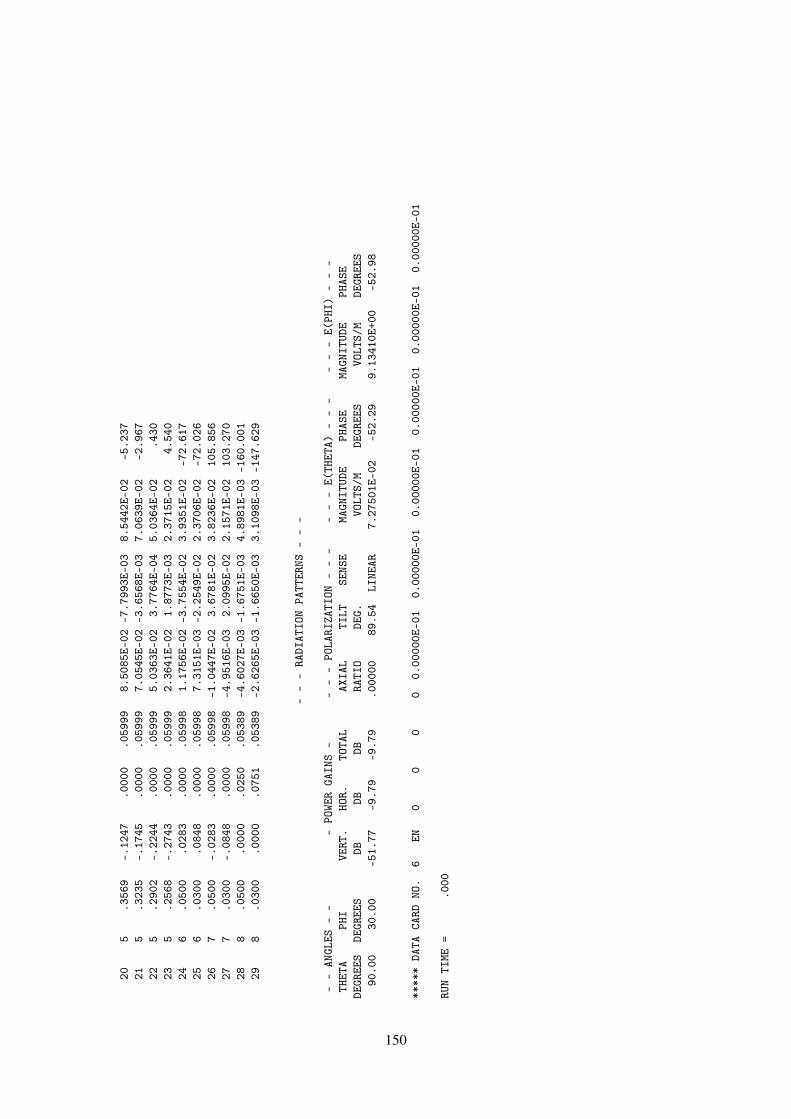
205
.356
9-.
1247
.000
0.0
5999
8.50
85E-
02-7
.799
3E-0
38.
5442
E-02
-5.2
3721
5.3
235
-.17
45.0
000
.059
997.
0545
E-02
-3.6
568E
-03
7.06
39E-
02-2
.967
225
.290
2-.
2244
.000
0.0
5999
5.03
63E-
023.
7764
E-04
5.03
64E-
02.4
3023
5.2
568
-.27
43.0
000
.059
992.
3641
E-02
1.87
73E-
032.
3715
E-02
4.54
024
6.0
500
.028
3.0
000
.059
981.
1756
E-02
-3.7
554E
-02
3.93
51E-
02-7
2.61
725
6.0
300
.084
8.0
000
.059
987.
3151
E-03
-2.2
549E
-02
2.37
06E-
02-7
2.02
626
7.0
500
-.02
83.0
000
.059
98-1
.044
7E-0
23.
6781
E-02
3.82
36E-
0210
5.85
627
7.0
300
-.08
48.0
000
.059
98-4
.951
6E-0
32.
0995
E-02
2.15
71E-
0210
3.27
028
8.0
500
.000
0.0
250
.053
89-4
.602
7E-0
3-1
.675
1E-0
34.
8981
E-03
-160
.001
298
.030
0.0
000
.075
1.0
5389
-2.6
265E
-03
-1.6
650E
-03
3.10
98E-
03-1
47.6
29
--
-RA
DIAT
ION
PATT
ERNS
--
-
--
ANGL
ES-
--
POWE
RGA
INS
--
--
POLA
RIZA
TION
--
--
--
E(TH
ETA)
--
--
--
E(PH
I)-
--
THET
APH
IVE
RT.
HOR.
TOTA
LAX
IAL
TILT
SENS
EMA
GNIT
UDE
PHAS
EMA
GNIT
UDE
PHAS
EDE
GREE
SDE
GREE
SDB
DBDB
RATI
ODE
G.VO
LTS/
MDE
GREE
SVO
LTS/
MDE
GREE
S90
.00
30.0
0-5
1.77
-9.7
9-9
.79
.000
0089
.54
LINE
AR7.
2750
1E-0
2-5
2.29
9.13
410E
+00
-52.
98
****
*DA
TACA
RDNO
.6
EN0
00
00.
0000
0E-0
10.
0000
0E-0
10.
0000
0E-0
10.
0000
0E-0
10.
0000
0E-0
10.
0000
0E-0
1
RUN
TIME
=.0
00
150

5 Error Messages
5.1 gNEC Errors
Not Yet Implemented.
5.2 NEC2 Errors
1. Message : CHECK DATA, PARAMETER SPECIFYING SEGMENT POSITION IN A GROUP OFEQUAL TAGS CANNOT BE ZERO
Routine : ISEGNOComment : This error results from an input data error and may occur at any point where a tag
number is used to identify a segment. Execution terminated. Data on the NT, TL,EX, and PT cards should be checked.
2. Message : CONNECT - SEGMENT CONNECTION ERROR FOR SEGMENT __Routine : CONNECTComment : Possible causes : number of segments at a junction exceeds limit; segment lengths
are zero; array overflow.
3. Message : DATA FAULT ON LOADING CARD NO. = __ ITAG STEP1 = __ ISGREATER THAN ITAG STEP2 = __
Routine : MAINComment : When several segments are loaded, the number of the second segment specified
must be greater than the number of the first segment. Execution terminated.
4. Message : EOF ON UNIT __ NBLKS = __ NEOF = __Routine : BLCKIN, entry point of BLCKOTComment : An end of file has been encountered while reading data from the unit. NBLKS
determines how many records are read from the unit. NEOF is a flag to indicatewhich call to BLCKIN initiated the read. If NEOF= 777, this diagnostic is normaland execution will continue. Otherwise, an error is indicated and execution willterminate.
5. Message : ERROR - ARC ANGLE EXCEEDS 360 DEGREESRoutine : ARCComment : Error on GA card.
6. Message : ERROR - B LESS THAN A IN ROM2Routine : ROM2Comment : Program malfunction.
7. Message : ERROR - FR/GN CARD IS NOT ALLOWED WITH N.G.F.Routine : MAINComment : See section III-5.
8. Message : ERROR - CORNERS OF QUADRILATERAL PATCH DO NOT LIE IN A PLANERoutine : PatchComment : The four corners of a quadrilateral patch (SP card) must lie in a plane.
9. Message : ERROR - COUPLING IS NOT BETWEEN 0 AND 1Routine : CoupleComment : Inaccuracy in solution or error in data.
151

10. Message : ERROR - GF MUST BE FIRST GEOMETRY DATA CARDRoutine : DATAGNComment : See section III-5.
11. Message : ERROR IN GROUND PARAMETERS - COMPLEX DIELECTRIC CONSTANTFROM FILE IS ____ REQUESTED ____
Routine : MAINComment : Complex dielectric constant from file TAPE21 does not agree with data from GN
and FR cards.
12. Message : ERROR - INSUFFICIENT STORAGE FOR INTERACTION MATRICES.IRESRV, IMAT. NEQ. NEQ2 = __
Routine : FBNGFComment : Array storage exceeded in NGF solution.
13. Message : ERROR - INSUFFICIENT STORAGE FOR MATRIXRoutine : FBLOCKComment : Array storage for matrix is not sufficient for out-of-core solution.
14. Message : ERROR - NETWORK ARRAY DIMENSIONS TOO SMALLRoutine : NETWKComment : The number of different segments to which transmission lines or network ports
are connected exceeds array dimensions. Execution terminated. Array size in theoriginal NEC deck is 30. Refer to array dimensio limitations in Part II for changingarray sizes.
15. Message : ERROR - LOADING MAY NOT BE ADDED TO SEGMENTS IN N.G.F.SECTION
Routine : LOADComment : See section III-5.
16. Message : ERROR - N.G.F. IN USE. CANNOT WRITE NEW N.G.F.Routine : MAIN
17. Message : ERROR - NO. NEW SEGMENTS CONNECTED TO N.G.F. SEGMENTS ORPATCHES EXCEEDS LIMIT
Routine : CONECTComment : Array dimension limit.
18. Message : FAULTY DATA CARD LABEL AFTER GEOMETRY SECTIONRoutine : MAINComment : A card with an unrecognizable mnemonic has been encountered in the program
control cards following the geometry cards. Execution terminated.
19. Message : GEOMETRY DATA CARD ERRORRoutine : DATAGNComment : A geometry data card was expected, but the card mnemonic is not that of a geom-
etry card. Execution terminated. After the GE card in a data deck, the possiblegeometry mnemonics are GE, GM, GR, GS, GW, GX, SP, and SS. The GE cardmust be used to terminate the geometry cards.
20. Message : GEOMETRY DATA ERROR - - PATCH __ LIES IN PLANE OF SYMMETRYRoutine : REFLC
21. Message : GEOMETRY DATA ERROR - - SEGMENT __ EXTENDS BELOW GROUNDRoutine : CONECT
152

Comment : When ground is specified on the GE card, no segment may extend below the XYplane. Execution terminated.
22. Message : GEOMETRY DATA ERROR - - SEGMENT __ LIES IN GROUND PLANERoutine : CONECTComment : When ground is specified on the GE card, no segment should lie in the XY plane.
Execution terminated.
23. Message : GEOMETRY DATA ERROR - - SEGMENT __ LIES IN PLANE OF SYMMETRYRoutine : REFLCComment : A segment may not lie in or cross a plane of symmetry about which the structure
is reflected since the segment and its image will coincide or cross. Executionterminated.
24. Message : IMPROPER LOAD TYPE CHOSEN, REQUESTED TYPE IS __Routine : LOADComment : Valid load types (LDTYP on the LD card) are from 0 through 5. Execution termi-
nated.
25. Message : INCORRECT LABEL FOR A COMMENT CARDRoutine : MAINComment : The program expected a comment card, with mnemonic CM or CE, but encoun-
tered a different mnemonic. Execution terminated. Comment cards must be thefirst cards in a data set, and the comments must be terminated by the CE mnemonic.
26. Message : LOADING DATA CARD ERROR, NO SEGMENT HAS AN ITAG = __Routine : LOADComment : ITAG specified on an LD card could not be found as a segment tag. Execution
terminated.
27. Message : NO SEGMENT HAS AN ITAG OF __Routine : ISEGNOComment : This error results from faulty input data and can occur at any point where a tag
number is used to identify a segment. Execution terminated. Tag numbers on theNT, TL, EX, CP, PQ, and PT cards should be checked.
28. Message : NOTE, SOME OF THE ABOVE SEGMENTS HAVE BEEN LOADED TWICE,IMPEDANCES ADDED
Routine : LOADComment : A segment or segments have been loaded by two or more LD cards. The
impedances of the loads have been added in series. This is only an informativemessage. Execution continues.
29. Message : NUMBER OF EXCITATION CARDS EXCEEDS STORAGE ALLOTTEDRoutine : MAINComment : The number of voltage source excitations exceeds array dimensions. Execution
terminated. The dimensions in the original NEC deck allow 10 voltage sources.Refer to Array Dimension Limitations in Part II to change the dimensions.
30. Message : NUMBER OF LOADING CARDS EXCEEDS STORAGE ALLOTTEDRoutine : MAINComment : The number of LD cards exceeds array dimension. Execution terminated. The
dimension in the original NEC deck allows 30 LD cards. Refer to Part II to changethe dimensions.
153
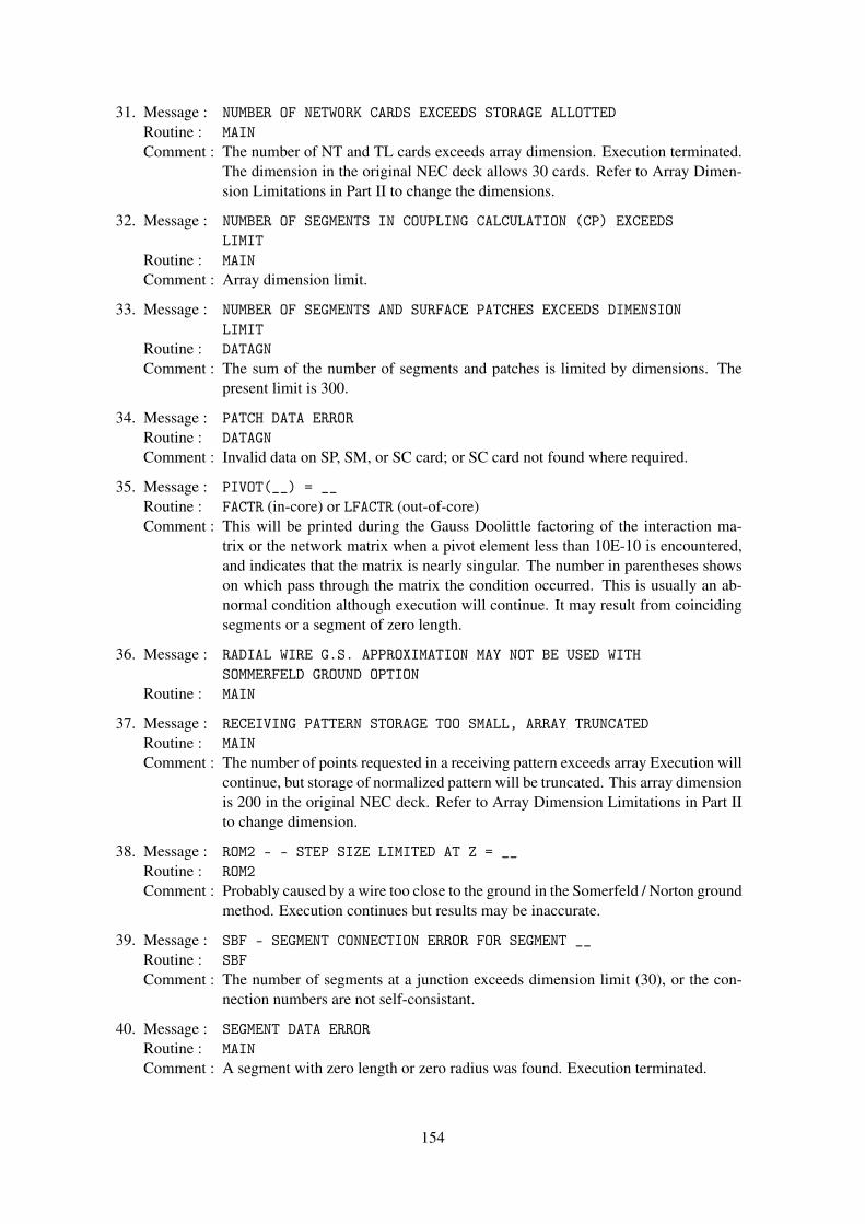
31. Message : NUMBER OF NETWORK CARDS EXCEEDS STORAGE ALLOTTEDRoutine : MAINComment : The number of NT and TL cards exceeds array dimension. Execution terminated.
The dimension in the original NEC deck allows 30 cards. Refer to Array Dimen-sion Limitations in Part II to change the dimensions.
32. Message : NUMBER OF SEGMENTS IN COUPLING CALCULATION (CP) EXCEEDSLIMIT
Routine : MAINComment : Array dimension limit.
33. Message : NUMBER OF SEGMENTS AND SURFACE PATCHES EXCEEDS DIMENSIONLIMIT
Routine : DATAGNComment : The sum of the number of segments and patches is limited by dimensions. The
present limit is 300.
34. Message : PATCH DATA ERRORRoutine : DATAGNComment : Invalid data on SP, SM, or SC card; or SC card not found where required.
35. Message : PIVOT(__) = __Routine : FACTR (in-core) or LFACTR (out-of-core)Comment : This will be printed during the Gauss Doolittle factoring of the interaction ma-
trix or the network matrix when a pivot element less than 10E-10 is encountered,and indicates that the matrix is nearly singular. The number in parentheses showson which pass through the matrix the condition occurred. This is usually an ab-normal condition although execution will continue. It may result from coincidingsegments or a segment of zero length.
36. Message : RADIAL WIRE G.S. APPROXIMATION MAY NOT BE USED WITHSOMMERFELD GROUND OPTION
Routine : MAIN
37. Message : RECEIVING PATTERN STORAGE TOO SMALL, ARRAY TRUNCATEDRoutine : MAINComment : The number of points requested in a receiving pattern exceeds array Execution will
continue, but storage of normalized pattern will be truncated. This array dimensionis 200 in the original NEC deck. Refer to Array Dimension Limitations in Part IIto change dimension.
38. Message : ROM2 - - STEP SIZE LIMITED AT Z = __Routine : ROM2Comment : Probably caused by a wire too close to the ground in the Somerfeld / Norton ground
method. Execution continues but results may be inaccurate.
39. Message : SBF - SEGMENT CONNECTION ERROR FOR SEGMENT __Routine : SBFComment : The number of segments at a junction exceeds dimension limit (30), or the con-
nection numbers are not self-consistant.
40. Message : SEGMENT DATA ERRORRoutine : MAINComment : A segment with zero length or zero radius was found. Execution terminated.
154

41. Message : STEP SIZE LIMTED AT Z = __Routine : INTX, HFXComment : The numerical integration to compute interaction matrix elements, using the
Romberg variable interval width method, was limited by the minimum allowedstep size. Execution will continue. An inaccuracy may occur but is usually notserious. May result from thin wire or wire close to the ground.
42. Message : STORAGE FOR IMPEDANCE NORMALIZATION TOO SMALL, ARRAYTRUNCATED
Routine : MAINComment : The number of frequencies on an FR card exceeds the array dimension for
impedance normalization. An impedance beyond the limit will not be normalized.Execution continues. The limit is 50 in the original NEC deck. Refer to ArrayDimension Limitations in Part II to change limit.
43. Message : SYMMETRY ERROR - NROW, NCOL = __Routine : FBLOCKComment : Array overflow or program malfunction.
44. Message : TBF - SEGMENT CONNECTION ERROR FOR SEGMENT __Routine : TBFComment : Same as error 39.
45. Message : TRIO - SEGMENT CONNECTION ERROR FOR SEGMENT __Routine : TRIOComment : Same as error 39.
46. Message : WHEN MULTIPLE FREQUENCIES ARE REQUESTED, ONLY ONE NEAR FIELDCARD CAN BE USED - LAST CARD READ IS USED
Routine : MAINComment : Execution continues.
155

References
[1] GJ Burke and AJ Pogio Numerical electromagnetics code (NEC-1), Part I: NEC ProgramDescription - Theory, to be publicised, Lawrence Livermore Laboratory, Livermore, CA.1977 (content same as NOSC TD 116, Part I)
[2] Numerical electromagnetics code (NEC-1), Part II: NEC Program Description - Code, tobe publicised, Lawrence Livermore Laboratory, Livermore, CA. 1977 (content same as NOSCTD 116, Part II)
[3] Poggio, A.J. and Adam, R. W., Approximations for Terms Related to the Kernel in Thin-Wire Integral Equations, Lawerence Livermore Laboratory, Livermore, CA. Rept. UCRL-51985, December 19, 1977
[4] Albertsen, N. C., Hansen, J.E., and Jensen, N. E., Computation of Space, Lyngby, Denmark,June 1972.
[5] Sengupta, D. L., Electromagnetic and Acoustic Scattering by Simple Shapes, Chapter 10,J. J. Bowman, T. B. Asenior and P. L. E. Uslenghi, Editors, North-Holland Publishing com-pany, Amsterdam, 1969.
156