go good gators! luck! - university of florida · (4%) c) precisely how long does it take to send...
TRANSCRIPT

University of Florida EEL 3744—Spring 2017 Dr. Eric M. Schwartz
Department of Electrical & Computer Engineering 22 March 2017 21-Apr-17 1:12 PM
Page 1/14 Exam 2
,
Last Name , First Name Instructions:
Good
luck!
Go
Gators!
Champion NaviGator AMS team in Hawaii.
Turn off all cell phones and other noise making devices
and put away all electronics. Show all work on the front of the test papers. If you need more room, make a
clearly indicated note on the front of the page, "MORE ON BACK", and use the
back. The back of the page will not be graded without an indication on the front.
You may use any of your XMEGA documents with limited added material;
highlighting and tagging is permissible. You may not use any notes (mine or yours),
examples, homework, labs, books, calculators, computer, electronic devices, etc.
CLEARLY write your name at the top of this test page (and, if you remove
the staple, all others). Be sure your exam consists of 14 distinct pages. Sign your name and add the date below.
(If we struggle to read your name, you will lose points.)
The space provided does not necessarily represent the amount of writing necessary.
You must pledge and sign this page in order for a grade to be assigned.
In programs, the use of comments results in more partial credit.
Read each question carefully and follow the instructions.
The point values for problems may be changed at prof’s discretion.
Part of your grade on tests, quizzes, labs, etc. is based not only on solving the problem you are presented with, but the
manner in which you solve it. For example, there is a difference between two programs that meet the given specifications,
but one is an elegant, extensible 20-line solution, while the other is an obfuscated 100-line program that also meets the
specifications but would be difficult to extend later. Just as your future employer would value the latter program less than
the first, so will I in grading your assignments.
This exam counts for 20.7-24.3% of your total grade.
Unless otherwise stated assume the following:
The oscillator frequency is precisely 2 MHz.
The code should run on an ATxmega128A1U as configured on the Out of the Box uPAD and uPAD Base Board without
any additional peripherals.
You can assume the standard bit equates that I have used in class examples (e.g., BIT0 = 0b0000 0001,
BIT76 = 0b1100 0000b, INV76 = 0b0011 1111) have already been done for you.
PLEDGE:
On my honor as a University of Florida student, I certify that I have neither given
nor received any aid on this examination, nor I have seen anyone else do so.
__________________________ _____________________________ ________________
PRINT YOUR NAME SIGN YOUR NAME DATE (22 Mar 17)
Regrade comments below. Give page # & problem # and reason for the petition.
Problem Available Points
1 37
2 20
3 7
4 10
5 15
6 11
TOTAL 100
May the Schwartz
be with you!
University of Florida EEL 3744—Spring 2017 Dr. Eric M. Schwartz
Department of Electrical & Computer Engineering 22 March 2017 21-Apr-17 1:12 PM
Page 2/14 Exam 2
,
Last Name , First Name
Device/Memory Blocks
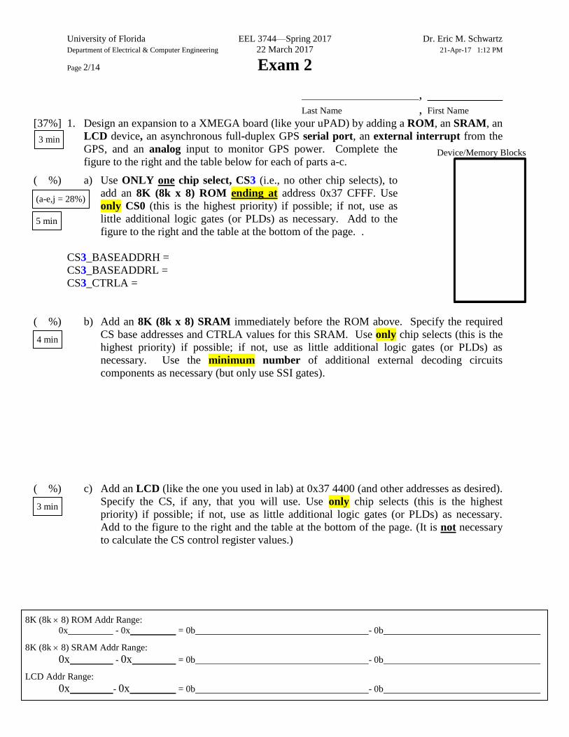
8K (8k 8) ROM Addr Range:
0x - 0x = 0b - 0b
8K (8k 8) SRAM Addr Range:
0x - 0x = 0b - 0b
LCD Addr Range:
0x - 0x = 0b - 0b
[37%] 1. Design an expansion to a XMEGA board (like your uPAD) by adding a ROM, an SRAM, an
LCD device, an asynchronous full-duplex GPS serial port, an external interrupt from the
GPS, and an analog input to monitor GPS power. Complete the
figure to the right and the table below for each of parts a-c.
( %) a) Use ONLY one chip select, CS3 (i.e., no other chip selects), to
add an 8K (8k x 8) ROM ending at address 0x37 CFFF. Use
only CS0 (this is the highest priority) if possible; if not, use as
little additional logic gates (or PLDs) as necessary. Add to the
figure to the right and the table at the bottom of the page. .
CS3_BASEADDRH =
CS3_BASEADDRL =
CS3_CTRLA =
( %) b) Add an 8K (8k x 8) SRAM immediately before the ROM above. Specify the required
CS base addresses and CTRLA values for this SRAM. Use only chip selects (this is the
highest priority) if possible; if not, use as little additional logic gates (or PLDs) as
necessary. Use the minimum number of additional external decoding circuits
components as necessary (but only use SSI gates).
( %) c) Add an LCD (like the one you used in lab) at 0x37 4400 (and other addresses as desired).
Specify the CS, if any, that you will use. Use only chip selects (this is the highest
priority) if possible; if not, use as little additional logic gates (or PLDs) as necessary.
Add to the figure to the right and the table at the bottom of the page. (It is not necessary
to calculate the CS control register values.)
3 min
(a-e,j = 28%)
5 min
4 min
3 min
University of Florida EEL 3744—Spring 2017 Dr. Eric M. Schwartz
Department of Electrical & Computer Engineering 22 March 2017 21-Apr-17 1:12 PM
Page 3/14 Exam 2
,
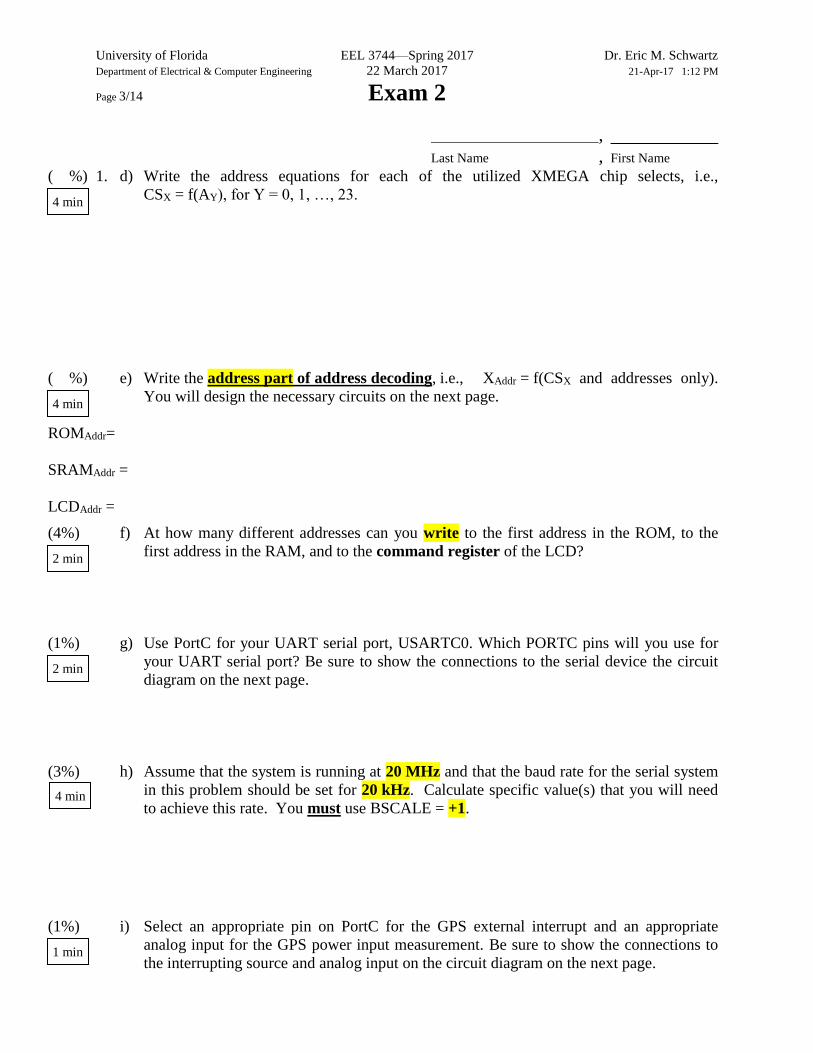
Last Name , First Name ( %) 1. d) Write the address equations for each of the utilized XMEGA chip selects, i.e.,
CSX = f(AY), for Y = 0, 1, …, 23.
( %) e) Write the address part of address decoding, i.e., XAddr = f(CSX and addresses only).
You will design the necessary circuits on the next page.
ROMAddr=
SRAMAddr =
LCDAddr =
(4%) f) At how many different addresses can you write to the first address in the ROM, to the
first address in the RAM, and to the command register of the LCD?
(1%) g) Use PortC for your UART serial port, USARTC0. Which PORTC pins will you use for
your UART serial port? Be sure to show the connections to the serial device the circuit
diagram on the next page.
(3%) h) Assume that the system is running at 20 MHz and that the baud rate for the serial system
in this problem should be set for 20 kHz. Calculate specific value(s) that you will need
to achieve this rate. You must use BSCALE = +1.
(1%) i) Select an appropriate pin on PortC for the GPS external interrupt and an appropriate
analog input for the GPS power input measurement. Be sure to show the connections to
the interrupting source and analog input on the circuit diagram on the next page.
4 min
4 min
1 min
2 min
4 min
2 min
University of Florida EEL 3744—Spring 2017 Dr. Eric M. Schwartz
Department of Electrical & Computer Engineering 22 March 2017 21-Apr-17 1:12 PM
Page 4/14 Exam 2
,
Last Name , First Name
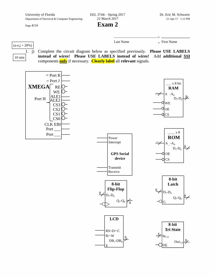
____ x 8
ROM
CS
OE
8
__A__-A0
D7-D0
___ x 8 bit
RAM
WE
CS
OE
8A -A0
D7-D0
__
LCD
R/~W
E
8
RS=D/~C
DB7-DB0
D7-D0
G
8-bit
Latch
8Q7-Q0
8
D7-D0
8-bit
Flip-Flop
8Q7-Q0
8
XMEGA
ALE1
= Port K
CLK EBI
WE
= Port J
Port ___
ALE2
RE
Port ___
Port H
CS3CS2CS1CS0
GPS Serial
device
Transmit
Receive
Power
Interrupt
1. j) Complete the circuit diagram below as specified previously. Please USE LABELS
instead of wires! Please USE LABELS instead of wires! Add additional SSI
components only if necessary. Clearly label all relevant signals. 10 min
(a-e,j = 28%)
University of Florida EEL 3744—Spring 2017 Dr. Eric M. Schwartz
Department of Electrical & Computer Engineering 22 March 2017 21-Apr-17 1:12 PM
Page 5/14 Exam 2
,
Last Name , First Name [20%] 2. Answer or solve each of the following short questions
(3%) a) Explain how you might use an interrupt with the keypad and why this would be a better
solution than what you did in lab. Be specific about any XMEGA systems that you might
want to use.
(1%) b) In C, when should you use floats instead of integers? When should you use double
instead of float?
(4%) c) Precisely how long does it take to send 1,000 blocks of 7-bit data when using the
following serial communication specifications: 5 kHz BAUD rate, 1 start bit, 2 stop bits,
and no parity bits.
(3%) d) What is double buffering in the XMEGA’s asynchronous serial communications
transmitter and how is it used?
4 min
4 min
2 min
2 min

University of Florida EEL 3744—Spring 2017 Dr. Eric M. Schwartz
Department of Electrical & Computer Engineering 22 March 2017 21-Apr-17 1:12 PM
Page 6/14 Exam 2
,
Last Name , First Name (2%) 2. e) Why should you use the busy flag when using the LCD? What is the alternative, if any?
(2%) f) When a branch instruction condition is true, how does the processor determine the correct
destination?
(2%) g) If EBI_CTRL = 0b0010 1011 = 0x2B, which address and/or data lines are time-
multiplexed?
(3%) h) Assume that you properly configured an SCI receiver interrupt and that with one actual
received value, you get a continuous stream of interrupts, one after another. What is the
likely error?
3 min
3 min
3 min
2 min
University of Florida EEL 3744—Spring 2017 Dr. Eric M. Schwartz
Department of Electrical & Computer Engineering 22 March 2017 21-Apr-17 1:12 PM
Page 7/14 Exam 2
,
Last Name , First Name (7%) 3. Write an assembly language subroutine (called EVEN_PAR) to determine if the byte at
X = 0x3744 (and RAMPX = 0) in data memory has even parity. Return a 0x1 on the stack if
the answer was yes and a 0 if the answer is no. Assume X already has the required value.
Labels Assembly Instructions Comments
7 min
University of Florida EEL 3744—Spring 2017 Dr. Eric M. Schwartz
Department of Electrical & Computer Engineering 22 March 2017 21-Apr-17 1:12 PM
Page 8/14 Exam 2
,
Last Name , First Name [10%] 4. In the XMEGA’s analog to digital converter (ADC), when using signed mode, the negative
reference voltage is just the negative of the high reference voltage. This is not the case in
some processors and some external ADC chips, where the two references are independent.
This problem will use a non-XMEGA ADC. This problem’s ADC system is signed, uses
5 bits, and has an analog input range from 2.0 V to +5.0 V (VRefL and VRefH,
respectively). Show all work in each of the problems below. This problem may require
basic arithmetic. You may leave your answer for parts a and b in the form of
y = f(x) = ax b, where a and b are floating point numbers or y = f(x) = (ax b)/c, where a,
b, and c are integers. Please provide numbers (not expressions) or “not valid” for parts c and
d.
(4%) a) Derive a formula to determine the analog voltage (v in decimal) from the 5-bit signed
digital ADC value (ADC in decimal), v = f( ADC ). Hint: A graph might help.
v =
(2%) b) Derive a form ADC = f( v ).
ADC =
(2%) c) If v = 3.7 V, what is the captured ADC value (in decimal and signed binary)? If the
value is not valid, write not valid?
ADC =
(2%) d) What is the voltage (in decimal) if the ADC returns a value of ADC = 0b11111? If the
value is not valid, write not valid?
v =
4 min
4 min
2 min
2 min
2 min

University of Florida EEL 3744—Spring 2017 Dr. Eric M. Schwartz
Department of Electrical & Computer Engineering 22 March 2017 21-Apr-17 1:12 PM
Page 9/14 Exam 2
,
Last Name , First Name [15%] 5. In this problem you read an ADC pin to take 32 samples, one sample every 37 ms, and store
the average of the 32 samples in a table, AVG_TAB. Store a total of 256 averages. When
done generating the 256 averages, repeat the process, overwriting the first 256 averages.
Assume that an RTC initialization function (RTC_INIT) has already been written to
generate an RTC interrupt every 1 ms, i.e., you should NOT write this function. You must
write an ADC system initialization function, ADC_INIT. Your RTC interrupt service routine
(RTC_ISR) and ADC sample (AD_Sample) function should sample and store a value at the
appropriate location in table RAW_TAB. When the 32nd sample is taken, calculate the
average and store it in AVG_TAB. After the 256th average is stored, the next average should
be stored at the beginning of the AVG_TAB. You will write a complete C program in the
next several parts (except the RTC initialization), including the main routine, the ADC
initialization function, RTC interrupt service routine, and the AD_Sample function. After
executing the required initializations, the main routine should toggle an output at PortC bit 3
as fast as possible (and do nothing else). Assume a raw XMEGA for this problem, i.e., NOT
a uPAD.
(6%) a) Write a complete C main program below, initializing the appropriate necessary systems.
You can assume that the RTC initialization program (RTC_INIT) was already written,
so you can use it. (Note: There is more room on the next page.)
C Code Comments (or More C Code)
6 min
4 min

University of Florida EEL 3744—Spring 2017 Dr. Eric M. Schwartz
Department of Electrical & Computer Engineering 22 March 2017 21-Apr-17 1:12 PM
Page 10/14 Exam 2
,
Last Name , First Name 5. a) (Continued.) Repeated problem: Write a complete C main program below, initializing
the appropriate necessary systems. You can assume that the RTC initialization program
(RTC_INIT) was already written, so you can use it.
C Code Comments (or More C Code)

University of Florida EEL 3744—Spring 2017 Dr. Eric M. Schwartz
Department of Electrical & Computer Engineering 22 March 2017 21-Apr-17 1:12 PM
Page 11/14 Exam 2
,
Last Name , First Name (4%) 5. b) Write the ADC_INIT function to initialize the ADC appropriately so that the ADC
system is ready to acquire the necessary samples as specified above. Assume that the
ADC values are between 0 and 0.9 V and that 6-bit resolution is good enough. Use
single-ended ADC, PortA bit 7, an internal ADC reference, and no gain. If you need
more space, continue on the back or on the previous page; indicate this with a large note
to the grader.
C Code Comments (or More C Code)
5 min
University of Florida EEL 3744—Spring 2017 Dr. Eric M. Schwartz
Department of Electrical & Computer Engineering 22 March 2017 21-Apr-17 1:12 PM
Page 12/14 Exam 2
,
Last Name , First Name (5%) 5. c) Write the RTC interrupt service routine (RTC_ISR) and ADC sample (AD_Sample)
function here, as specified previously, i.e., your RTC interrupt service routine
(RTC_ISR) and ADC sample (AD_Sample) function should sample and store a value at
the appropriate location in table RAW_TAB. When the 32nd sample is taken, calculate
the average and store it in AVG_TAB. After the 256th average is stored, the next average
should be stored at the beginning of the AVG_TAB.
C Code Comments (or More C Code)
6 min
University of Florida EEL 3744—Spring 2017 Dr. Eric M. Schwartz
Department of Electrical & Computer Engineering 22 March 2017 21-Apr-17 1:12 PM
Page 13/14 Exam 2
,
Last Name , First Name [11%] 6. In this problem you will write parts of an assembly language program for an asynchronous
serial (UART) application. Assume that an assembly language subroutine (INIT_SCI) has
already been written to appropriately initialize the serial system of part 1g-h (i.e., USARTC0)
and use the information in part 1g for setting the baud rate to 20 kHz. Reminder: System is
running at 20 MHz and BSCALE = +1. Use 7-bit data, no parity, 1 start bit, and 2 stop bit.
Also assume that INIT_SCI initializes the system for transmitter interrupts and receiver
polling.
(3%) a) Write the SCI_TX_ISR interrupt vector initialization program fragment that would go in
the main assembly language routine.
Labels Instructions Comments
(8%) b) Assume a 100-byte table at TX_TAB exists in data memory. A 16-bit pointer at data
memory location TX_PTR points to the next value in the table to be transmitted. Write
an assembly language interrupt service routine (SCI_TX_ISR) to transmit a single byte
of the data pointed to by TX_PTR and update the TX_PTR as required. (Note: There is
more room on the next page.)
Labels Instructions Comments
7 min
4 min
2 min

University of Florida EEL 3744—Spring 2017 Dr. Eric M. Schwartz
Department of Electrical & Computer Engineering 22 March 2017 21-Apr-17 1:12 PM
Page 14/14 Exam 2
,
Last Name , First Name 6. b) (Continued.) Repeated problem: Assume a 100-byte table at TX_TAB exists in data
memory. A 16-bit pointer at data memory location TX_PTR points to the next value in
the table to be transmitted. Write an assembly language interrupt service routine
(SCI_TX_ISR) to transmit a single byte of the data pointed to by TX_PTR and update
the TX_PTR as required.
Labels Instructions Comments