go power! manual - pvpower.com | solar panels, pv solar ... power/gpsw600-3000user.pdf · go power!...
TRANSCRIPT
Go Power! Manual GP-SW3000 Inverter GP-SW2000 Inverter GP-SW1000 Inverter GP-SW600 Inverter

Go Power! GP-SW3000, GP-SW2000, GP-SW1000and GP-SW600Owner’s Manual
3
Contents
1. Introduction..................................................................................................4
2. Specifications ..............................................................................................5 2.1 GP-SW3000 W Inverter ......................................................................................... 5 2.2 GP-SW2000 W Inverter ......................................................................................... 6 2.3 GP-SW1000 W Inverter ......................................................................................... 7 2.4 GP-SW600 W Inverter ........................................................................................... 8
3. Inverter drawings.........................................................................................9 3.1 GP-SW3000 and GP-SW2000............................................................................... 9 3.2 GP-SW1000 ......................................................................................................... 11 3.3 GP-SW600 ........................................................................................................... 13
4. Installation..................................................................................................15 4.1 Where to install..................................................................................................... 15 4.2 Hook-up and testing ............................................................................................. 15 4.3 Hard Wire (GP-SW3000 and GP-SW2000 .......................................................... 16 4.4 Cables .................................................................................................................. 16 4.5 Grounding............................................................................................................. 17
5. Operation....................................................................................................18 5.1 Operating On/Off Switch ...................................................................................... 18 5.2 Input Level (battery voltage) indicator.................................................................. 18 5.3 Load Level Indicator............................................................................................. 18 5.4 Fault Indicator (GP-SW600)................................................................................. 18 5.5 Status Indicator (GP-SW1000, GP-SW2000 and GP-SW3000).......................... 18 5.6 Over Voltage Indicator (OVP) .............................................................................. 18 5.7 Low / Under Voltage Indicator (UVP)................................................................... 18 5.8 Over Temp Indicator (OTP).................................................................................. 19 5.9 Maximum Load / Overload Indicator (OLP) ......................................................... 19 5.10 Power Saving Indicator (GP-SW1000 and GP-SW2000) ................................ 19 5.11 What is Power Saving? (GP-SW1000, GP-SW2000 and GP-SW3000).......... 19 5.12 Remote ............................................................................................................. 20
6. Operating limits..........................................................................................21 6.1 Input voltage:........................................................................................................ 21
7. Troubleshooting.........................................................................................22 7.1 Common problems............................................................................................... 22 7.2 Troubleshooting Guide......................................................................................... 22
8. Maintenance ...............................................................................................23
9. Warranty .....................................................................................................24 9.1 Go Power! 2 Year Limited Warranty .................................................................... 24 9.2 Warranty Return Procedure ................................................................................. 25 9.3 Additional Information .......................................................................................... 26 9.4 Out of Warranty Items .......................................................................................... 26
10. Configuring your GP-SW3000, GP-SW2000, GP-SW1000, and GP-SW600...................................................................................................27
10.1 Configuring the Dip Switches GP-SW3000, GP-SW2000, and GP-SW1000 . 27 10.2 Other Dip Switches (Professional Installer Only) ............................................. 27
Go Power! GP-SW3000, GP-SW2000, GP-SW1000and GP-SW600Owner’s Manual
4
1. Introduction The Go Power! Sine Wave series models are used in a wide range of applications including remote homes, RVs, sailboats, and powerboats. It will operate most televisions and VCRs, personal computers, small appliances, and tools such as drills, sanders, grinders, mixers and blenders. The inverter must have a greater power rating than the load it provides power to. To get the most out of the power inverter, it must be installed and used properly. Please read the instructions in this manual before installing and using this model.
Go Power! GP-SW3000, GP-SW2000, GP-SW1000and GP-SW600Owner’s Manual
5
2. Specifications
2.1 GP-SW3000 W Inverter GP-SW3000
Specification 12 V 24 V
Continuous output power 3000 W
Surge rating 6000 W
Output waveform Sine Wave <3% THD
Output Voltage ± 3% 115 VAC RMS
Output Frequency ± 0.05% 50 / 60 Hz adjustable
Input voltage 10.5 to 15 V DC 21 to 30 V DC
Efficiency 85 to 92%
No load current draw / Powersave 2.0 A / 0.55 A 1.6 A / 0.35 A
Protection Overload, over temperature, over voltage, low voltage, short circuit, reverse polarity (fuse)
Low battery alarm ± 2% 10.5 V 21.0 V
Low battery shut-down ± 2% ≤ 10.0 V ≤ 20.0 V
Cooling Thermostatically-controlled fan
AC receptacle Dual GFCI
Dimensions (L x W x H) 17.8 x 8.2 x 6.5 inches (452 x 208 x 166 mm)
Weight 22 lb (9.8 kg)
Warranty 2 years
Inverter Install Kit GP-DC Kit 5 GP-DC Kit 3

Go Power! GP-SW3000, GP-SW2000, GP-SW1000and GP-SW600Owner’s Manual
6
2.2 GP-SW2000 W Inverter GP-SW2000
Specification 12 V 24 V
Continuous output power 2000 W
Surge rating 4000 W
Output waveform Sine Wave <3% THD
Output Voltage ± 3% 115 VAC RMS
Output Frequency ± 0.05% 50 / 60 Hz adjustable
Input voltage 10.5 to15 V DC 21 to 30 V DC
Efficiency 85-92%
No load current draw / Powersave 2.8 A / 0.6 A 1.5 A / 0.3 A
Protection Overload, over temperature, over voltage, low voltage, short circuit, reverse polarity (fuse)
Low battery alarm ± 2% 10.5 V 21.0 V
Low battery shut-down ± 2% ≤ 10.0 V ≤ 20.0 V
Cooling Thermostatically-controlled fan
AC receptacle Dual GFCI
Dimensions (L x W x H) 17.8 x 8.2 x 6.5 inches (452 x 208 x 160 mm)
Weight 21 lb (9.5 kg)
Warranty 2 years
Inverter Install Kit GP-DC Kit 4 GP-DC Kit 3
Go Power! GP-SW3000, GP-SW2000, GP-SW1000and GP-SW600Owner’s Manual
7
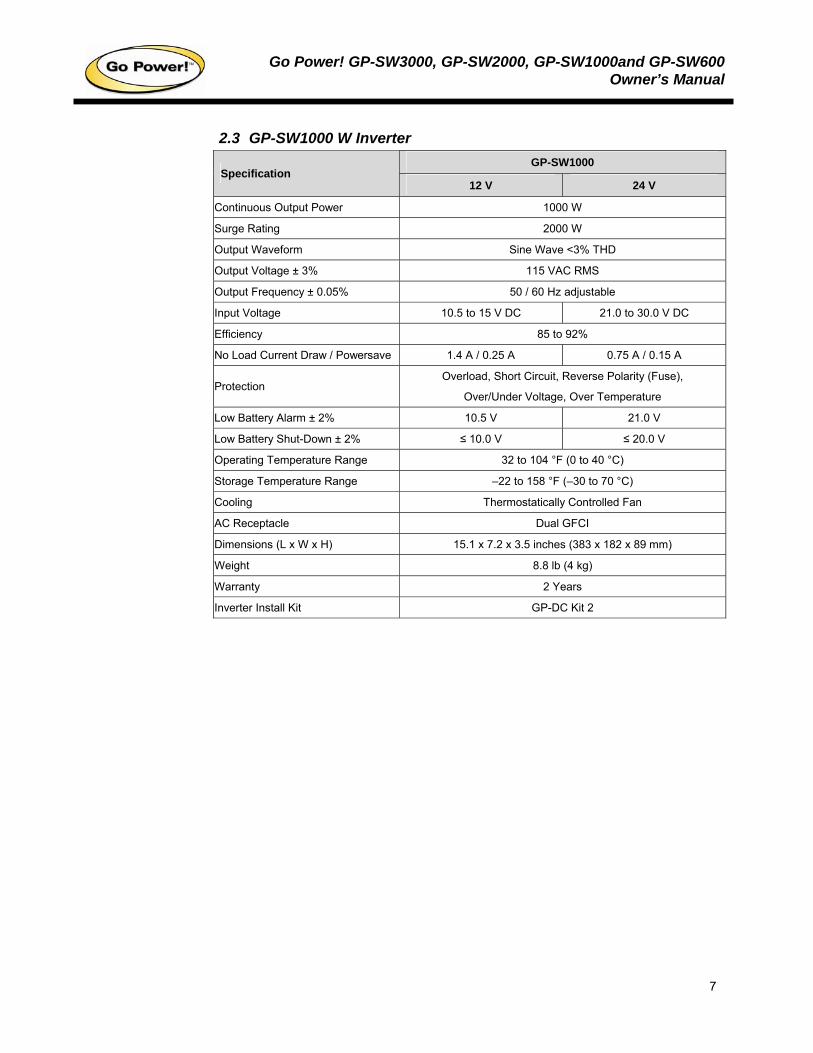
2.3 GP-SW1000 W Inverter GP-SW1000
Specification 12 V 24 V
Continuous Output Power 1000 W
Surge Rating 2000 W
Output Waveform Sine Wave <3% THD
Output Voltage ± 3% 115 VAC RMS
Output Frequency ± 0.05% 50 / 60 Hz adjustable
Input Voltage 10.5 to 15 V DC 21.0 to 30.0 V DC
Efficiency 85 to 92%
No Load Current Draw / Powersave 1.4 A / 0.25 A 0.75 A / 0.15 A
Protection Overload, Short Circuit, Reverse Polarity (Fuse),
Over/Under Voltage, Over Temperature
Low Battery Alarm ± 2% 10.5 V 21.0 V
Low Battery Shut-Down ± 2% ≤ 10.0 V ≤ 20.0 V
Operating Temperature Range 32 to 104 °F (0 to 40 °C)
Storage Temperature Range –22 to 158 °F (–30 to 70 °C)
Cooling Thermostatically Controlled Fan
AC Receptacle Dual GFCI
Dimensions (L x W x H) 15.1 x 7.2 x 3.5 inches (383 x 182 x 89 mm)
Weight 8.8 lb (4 kg)
Warranty 2 Years
Inverter Install Kit GP-DC Kit 2
Go Power! GP-SW3000, GP-SW2000, GP-SW1000and GP-SW600Owner’s Manual
8
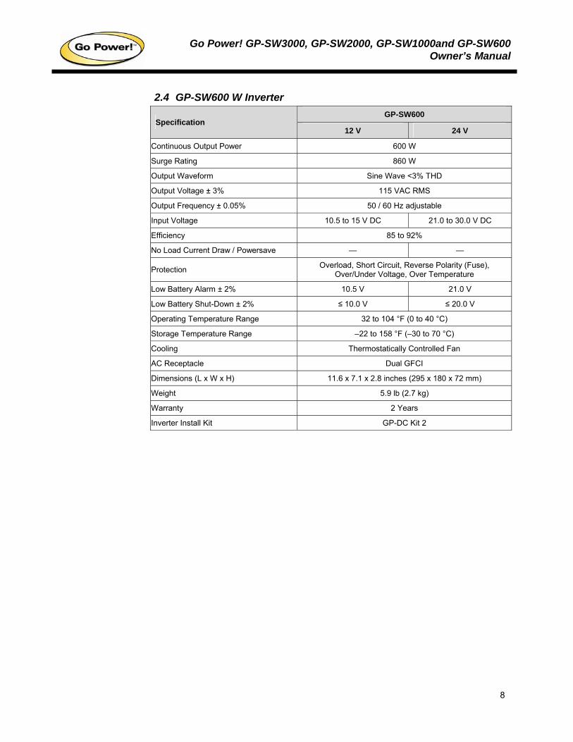
2.4 GP-SW600 W Inverter GP-SW600
Specification 12 V 24 V
Continuous Output Power 600 W
Surge Rating 860 W
Output Waveform Sine Wave <3% THD
Output Voltage ± 3% 115 VAC RMS
Output Frequency ± 0.05% 50 / 60 Hz adjustable
Input Voltage 10.5 to 15 V DC 21.0 to 30.0 V DC
Efficiency 85 to 92%
No Load Current Draw / Powersave — —
Protection Overload, Short Circuit, Reverse Polarity (Fuse), Over/Under Voltage, Over Temperature
Low Battery Alarm ± 2% 10.5 V 21.0 V
Low Battery Shut-Down ± 2% ≤ 10.0 V ≤ 20.0 V
Operating Temperature Range 32 to 104 °F (0 to 40 °C)
Storage Temperature Range –22 to 158 °F (–30 to 70 °C)
Cooling Thermostatically Controlled Fan
AC Receptacle Dual GFCI
Dimensions (L x W x H) 11.6 x 7.1 x 2.8 inches (295 x 180 x 72 mm)
Weight 5.9 lb (2.7 kg)
Warranty 2 Years
Inverter Install Kit GP-DC Kit 2
Go Power! GP-SW3000, GP-SW2000, GP-SW1000and GP-SW600Owner’s Manual
9
3. Inverter drawings
3.1 GP-SW3000 and GP-SW2000
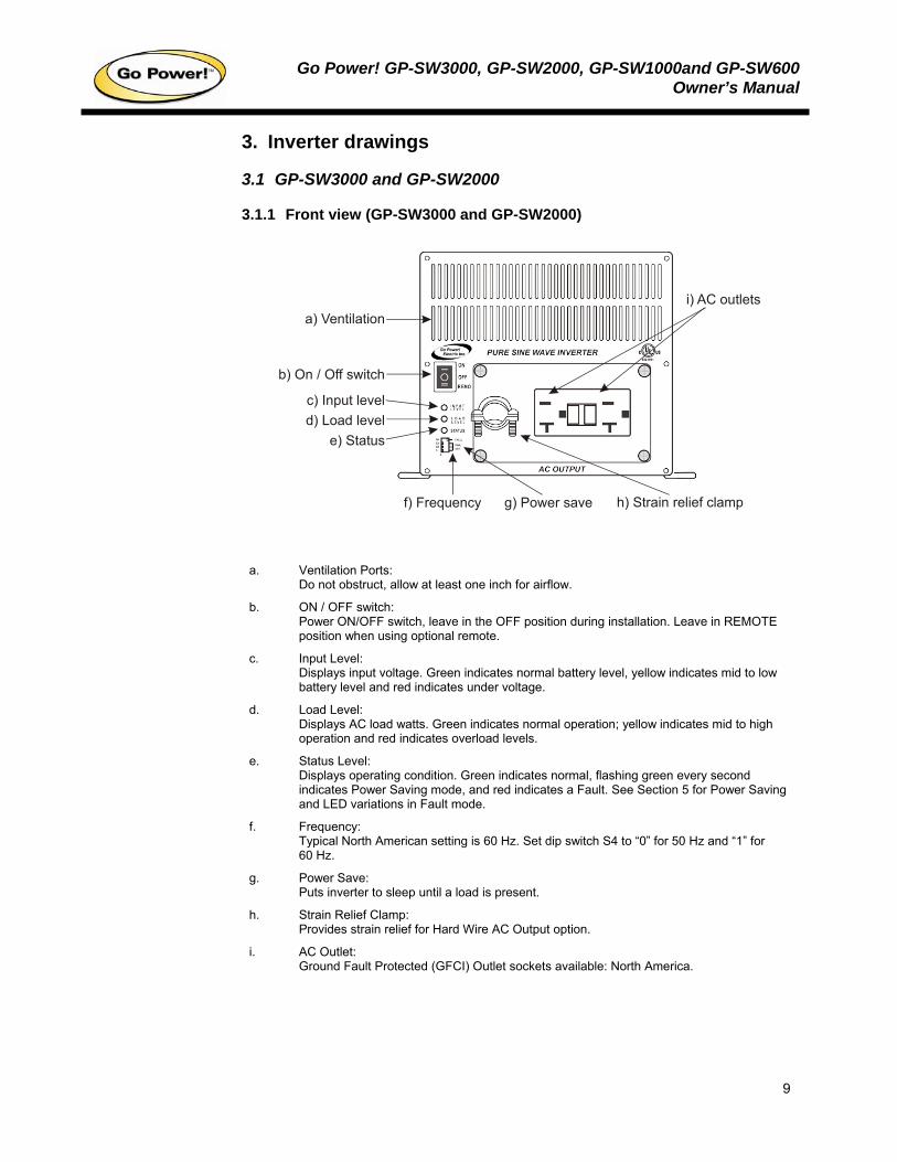
3.1.1 Front view (GP-SW3000 and GP-SW2000)
a) Ventilation
b) On / Off switch
c) Input leveld) Load level
e) Status
f) Frequency h) Strain relief clampg) Power save
i) AC outlets
a. Ventilation Ports:
Do not obstruct, allow at least one inch for airflow.
b. ON / OFF switch: Power ON/OFF switch, leave in the OFF position during installation. Leave in REMOTE position when using optional remote.
c. Input Level: Displays input voltage. Green indicates normal battery level, yellow indicates mid to low battery level and red indicates under voltage.
d. Load Level: Displays AC load watts. Green indicates normal operation; yellow indicates mid to high operation and red indicates overload levels.
e. Status Level: Displays operating condition. Green indicates normal, flashing green every second indicates Power Saving mode, and red indicates a Fault. See Section 5 for Power Saving and LED variations in Fault mode.
f. Frequency: Typical North American setting is 60 Hz. Set dip switch S4 to “0” for 50 Hz and “1” for 60 Hz.
g. Power Save: Puts inverter to sleep until a load is present.
h. Strain Relief Clamp: Provides strain relief for Hard Wire AC Output option.
i. AC Outlet: Ground Fault Protected (GFCI) Outlet sockets available: North America.
Go Power! GP-SW3000, GP-SW2000, GP-SW1000and GP-SW600Owner’s Manual
10
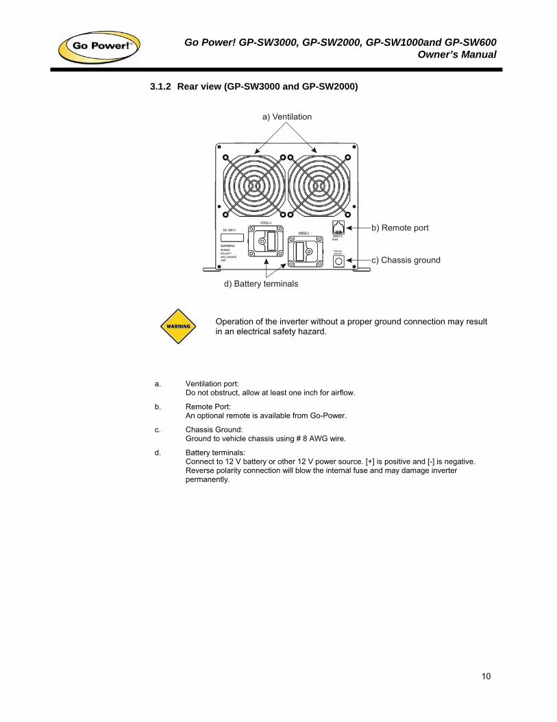
3.1.2 Rear view (GP-SW3000 and GP-SW2000)
a) Ventilation
d) Battery terminals
b) Remote port
c) Chassis ground
Operation of the inverter without a proper ground connection may result in an electrical safety hazard.
a. Ventilation port:
Do not obstruct, allow at least one inch for airflow.
b. Remote Port: An optional remote is available from Go-Power.
c. Chassis Ground: Ground to vehicle chassis using # 8 AWG wire.
d. Battery terminals: Connect to 12 V battery or other 12 V power source. [+] is positive and [-] is negative. Reverse polarity connection will blow the internal fuse and may damage inverter permanently.
Go Power! GP-SW3000, GP-SW2000, GP-SW1000and GP-SW600Owner’s Manual
11
3.2 GP-SW1000
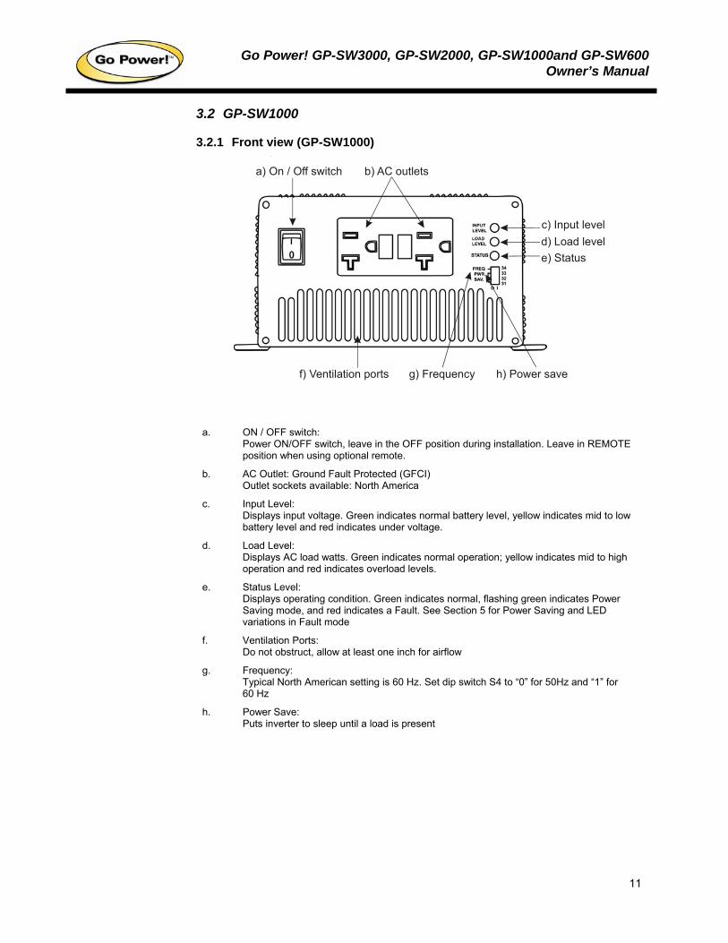
3.2.1 Front view (GP-SW1000)
a) On / Off switch
c) Input leveld) Load levele) Status
f) Ventilation ports h) Power saveg) Frequency
b) AC outlets
a. ON / OFF switch:
Power ON/OFF switch, leave in the OFF position during installation. Leave in REMOTE position when using optional remote.
b. AC Outlet: Ground Fault Protected (GFCI) Outlet sockets available: North America
c. Input Level: Displays input voltage. Green indicates normal battery level, yellow indicates mid to low battery level and red indicates under voltage.
d. Load Level: Displays AC load watts. Green indicates normal operation; yellow indicates mid to high operation and red indicates overload levels.
e. Status Level: Displays operating condition. Green indicates normal, flashing green indicates Power Saving mode, and red indicates a Fault. See Section 5 for Power Saving and LED variations in Fault mode
f. Ventilation Ports: Do not obstruct, allow at least one inch for airflow
g. Frequency: Typical North American setting is 60 Hz. Set dip switch S4 to “0” for 50Hz and “1” for 60 Hz
h. Power Save: Puts inverter to sleep until a load is present
Go Power! GP-SW3000, GP-SW2000, GP-SW1000and GP-SW600Owner’s Manual
12
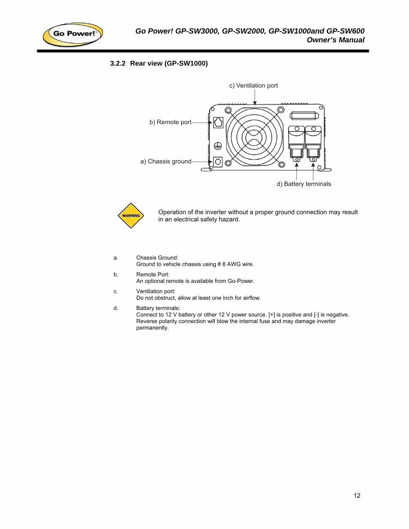
3.2.2 Rear view (GP-SW1000)
c) Ventilation port
b) Remote port
a) Chassis ground
d) Battery terminals
Operation of the inverter without a proper ground connection may result in an electrical safety hazard.
a. Chassis Ground:
Ground to vehicle chassis using # 8 AWG wire.
b. Remote Port: An optional remote is available from Go-Power.
c. Ventilation port: Do not obstruct, allow at least one inch for airflow.
d. Battery terminals: Connect to 12 V battery or other 12 V power source. [+] is positive and [-] is negative. Reverse polarity connection will blow the internal fuse and may damage inverter permanently.
Go Power! GP-SW3000, GP-SW2000, GP-SW1000and GP-SW600Owner’s Manual
13
3.3 GP-SW600
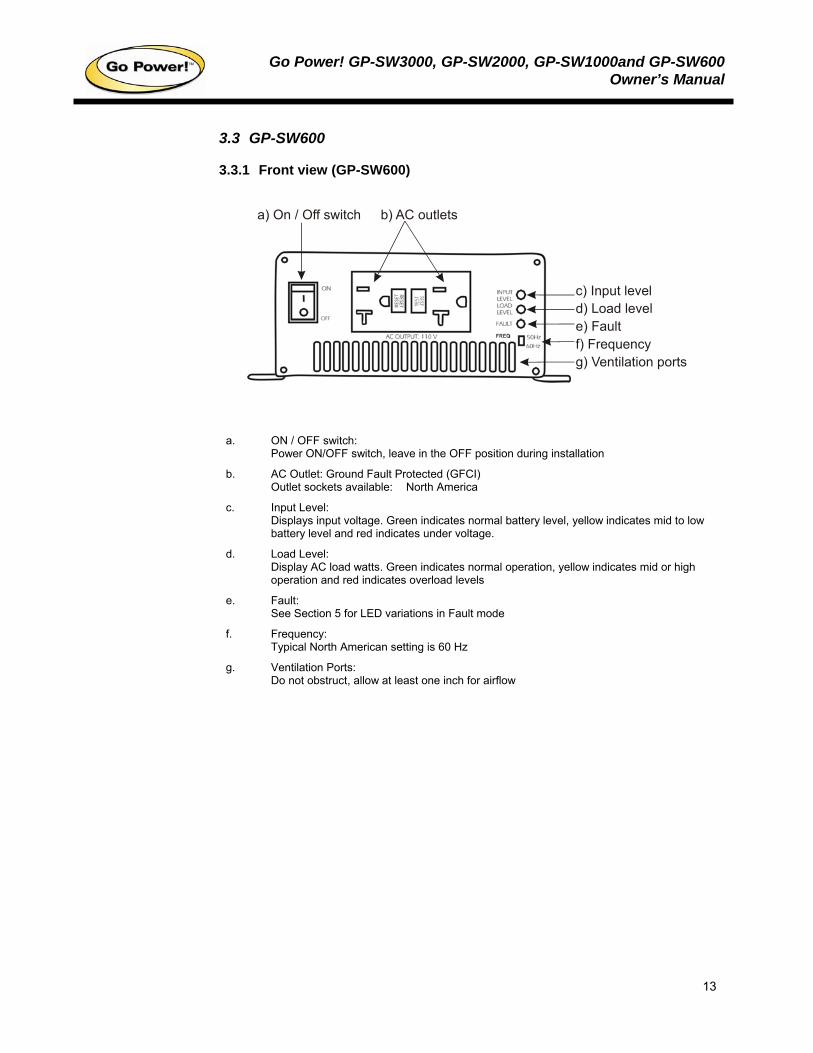
3.3.1 Front view (GP-SW600)
a) On / Off switch
c) Input leveld) Load levele) Fault
g) Ventilation portsf) Frequency
b) AC outlets
a. ON / OFF switch:
Power ON/OFF switch, leave in the OFF position during installation
b. AC Outlet: Ground Fault Protected (GFCI) Outlet sockets available: North America
c. Input Level: Displays input voltage. Green indicates normal battery level, yellow indicates mid to low battery level and red indicates under voltage.
d. Load Level: Display AC load watts. Green indicates normal operation, yellow indicates mid or high operation and red indicates overload levels
e. Fault: See Section 5 for LED variations in Fault mode
f. Frequency: Typical North American setting is 60 Hz
g. Ventilation Ports: Do not obstruct, allow at least one inch for airflow
Go Power! GP-SW3000, GP-SW2000, GP-SW1000and GP-SW600Owner’s Manual
14
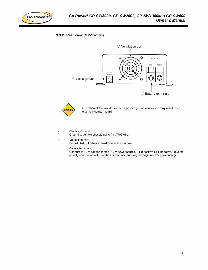
3.3.2 Rear view (GP-SW600)
b) Ventilation port
a) Chassis ground
c) Battery terminals
Operation of the inverter without a proper ground connection may result in an electrical safety hazard.
a. Chassis Ground:
Ground to vehicle chassis using # 8 AWG wire.
b. Ventilation port: Do not obstruct, allow at least one inch for airflow.
c. Battery terminals: Connect to 12 V battery or other 12 V power source. [+] is positive [-] is negative. Reverse polarity connection will blow the internal fuse and may damage inverter permanently.
Go Power! GP-SW3000, GP-SW2000, GP-SW1000and GP-SW600Owner’s Manual
15
4. Installation
4.1 Where to install The power inverter should be installed in a location that meets the following requirements:
Do not connect this inverter and another AC source (generator or utility power) to the AC wiring or AC loads at the same time. Doing so will destroy the inverter and void the warranty, regardless of the inverter’s on or off status. If you are using more than one AC source for the AC wiring or AC loads, it is highly recommended that you install an automatic transfer switch (GP-TS), available from Go-Power.
Dry – Do not allow water to drip or splash on the inverter.
Cool – Ambient air temperature should be between 32 and 104 °F (0 and 40 °C) (the cooler the better).
Ventilated – Allow at least two inches of clearance around the inverter for airflow. Ensure the ventilation openings on the rear and bottom of the unit are not obstructed.
Safe – Do not install the inverter in the same compartment as batteries, or in any compartment capable of igniting flammable liquids such as gasoline.
Inverter should be located within 10 feet (3 m) of the batteries.
4.2 Hook-up and testing
A reverse polarity connection will blow a fuse in the inverter and may permanently damage the inverter. Damage caused by reverse polarity connection is not covered by warranty.
For hook-up, please follow these guidelines:
1. Unpack and inspect your Go Power! Inverter, then check to see that the power switch is in the OFF position. Set up your power output according to Section 10, Configuring your Sine Wave.
2. Insert DC inverter cables (not included) to the power input terminals on the rear panel of the power inverter. The red terminal is positive (+) and black terminal is negative (-). Connect the cables into the terminals and tighten the terminal screw to clamp the wires securely.
3. Connect the cable from the negative terminal of the inverter to the negative terminal of the battery. Make a secure connection.
Loose connections result in excessive voltage drop and may cause overheated wires and melted insulation.
4. Before proceeding further, carefully check that the cable you have just connected connects from the negative terminal of inverter to the negative terminal of the power source (battery).
You may observe a spark when you make this connection since current may flow to charge capacitors in the power inverter. Do not make this connection in the presence of flammable fumes, as explosion or fire may result.
Go Power! GP-SW3000, GP-SW2000, GP-SW1000and GP-SW600Owner’s Manual
16
5. Install inverter fuse (not included) in positive lead. Fuse should be located within 12” of battery. Ensure all connections are tight and secure. (See Section 4.3)
6. Connect the cable from the positive terminal of inverter to the positive terminal of the battery. Make a secure connection.
7. Set the power switch to the ON position. Check the indicators on the front panel of the inverter. The Input Level LED should be green or yellow, depending on the voltage of the power source. If it is not, check your battery bank and the connections to the inverter.
8. Set the power inverter switch to the OFF position. The indicator lights may blink and the internal alarm may sound momentarily. This is normal. Plug the test load into the AC receptacle on the front panel of the inverter. Leave the test load switch OFF. (For the Hard Wire option, please see Section 4.3).
9. Set the power inverter switch to the ON position and turn the test load on; the inverter should supply power to the load. If you plan to measure the output voltage of the inverter, a true rms meter must be used for accurate readings.
The GFCI outlet and the Hard Wire terminal of the GP-SW3000 are rated for 20 amps or 2200 watts each. Do not exceed a combined load of 20 amps or 2200 watts for either the GFCI outlet or the Hard Wire terminal. Do Not jumper the GFCI outlet or the Hard Wire terminal together.
4.3 Hard Wire (GP-SW3000 and GP-SW2000
Ensure the inverter is turned off if connecting the Hard Wire option.
The GP-SW3000 and GP-SW2000 AC output may be hard wired into the inverter. Remove the four screws that surround the AC outlet and strain relief clamp to reveal a two-connection terminal strip. Feed a user-supplied power cable through the strain relief clamp, tighten the clamp, and make the connections.
The Black or HOT wire output is labeled “L” and the white or NEUTRAL wire output is labeled “N”. The Green or GROUND wire connection is labeled “FG” or with the standard ground symbol and is located to the right of the terminal strip. The National Electrical Code recommends no less than #12 gauge wire for this application. Seek professional assistance if you are unfamiliar with electrical wiring.
4.4 Cables
Install the inverter fuse into the positive lead. Fuse should be located within 12” of battery. Ensure all connections are tight and secure.
GP-SW600-12V: Please use 8 ft or less of #6 Cable with a 70 Amp fuse. GP-SW600-24V: Please use 8 ft or less of #8 Cable with a 70 Amp fuse.
A GP-DC Kit 2 suitable for both 12 and 24 V applications is available from Go Power Inc. (please use the included GP-SW600 crimp lugs for this application).
Go Power! GP-SW3000, GP-SW2000, GP-SW1000and GP-SW600Owner’s Manual
17
GP-SW1000-12V: Please use 10 ft or less of #4 Cable with a 110 Amp fuse. GP-SW1000-24V: Please use 10 ft or less of #6 Cable with a 70 Amp fuse.
A GP-DC Kit 2 suitable for both 12 and 24 V applications is available from Go Power Inc.
GP-SW2000-12V: Please use 10 ft or less of 2/0 Cable with a 300 Amp fuse. GP-SW2000-24V: Please use 10 ft or less of #2 Cable with a 200 Amp fuse.
A GP-DC Kit 4 suitable for 12 V and a GP-DC Kit 3 suitable for 24 V applications is available from Go Power Inc.
GP-SW3000-12V: Please use 10 ft or less of 4/0 Cable with a 400 Amp fuse. GP-SW3000-24V: Please use 10 ft or less of #2 Cable with a 200 Amp fuse.
A GP-DC Kit 5 suitable for 12 V and a GP-DC Kit 3 suitable for 24 V applications is available from Go Power Inc.
4.5 Grounding
The negative DC input of the power inverter is connected to the chassis. Do not install the power inverter in a positive ground DC system. A positive ground DC system has the positive terminal of the battery connected to the chassis of the vehicle or to the grounding point.
Do not operate the power inverter without connecting it to ground. Electrical shock hazard may result.
The power inverter has a lug on the rear panel [chassis ground]. This is to connect the chassis of the power inverter to ground. The ground terminals in the AC outlets on the front panel of the inverter are also connected to the ground lug.
The chassis ground lug must be connected to a grounding point, which will vary depending on where the power inverter is installed. In a vehicle, connect the chassis ground to the chassis of the vehicle. In a boat, connect to the boat's grounding systems. In a fixed location, connect the chassis ground lug to earth.
The neutral (common) conductor of the inverter AC output circuit is connected (bonded) to the chassis ground inside the inverter. Therefore, when the chassis is connected to ground, the neutral conductor will also be grounded. This conforms to national electrical code requirements that states that separately derived AC sources (such as inverters and generators) have their neutral tied to ground in the same way that the neutral conductor from the utility line is tied to ground at the AC breaker panel.
If the inverter is supplying power to equipment or a panel where the neutral and ground are connected (bonded), a ground loop will occur. If a ground loop occurs, the GFCI outlet will trip and output power from the inverter will be cut off. If your GFCI repeatedly needs to be reset, this would indicate a ground loop somewhere in your system. In this case, please have a qualified person inspect your electrical system or equipment.
Go Power! GP-SW3000, GP-SW2000, GP-SW1000and GP-SW600Owner’s Manual
18
5. Operation To operate the power inverter, turn it on using the ON/OFF switch on the front panel. The power inverter is now ready to deliver AC power to your loads. If you are operating several loads from the power inverter, turn them on separately after the inverter has been turned on. This will ensure that the power inverter does not have to deliver the starting currents for all the loads at once.
5.1 Operating On/Off Switch The ON/OFF switch turns the control circuit in the power inverter ON and OFF. It does not disconnect power from the power inverter. When the switch is in the OFF position, the power inverter draws no current from the battery. When the switch is in the ON position but with no load, the power inverter draws less than 2.5 W (GP-SW600), 14.4 W (GP-SW1000, GP-SW2000 and GP-SW3000) from the battery. When in Power Save mode the GP-SW1000, GP-SW2000 and GP-SW3000 will draw approximately 3.0 W from the battery.
5.2 Input Level (battery voltage) indicator The GP-SW600, GP-SW1000, GP-SW2000 and GP-SW3000 Input Level LED changes colour from green to yellow to red as battery voltage decreases from a resting voltage of 12.7 V - 10.5 V (12 V) or 25.4 V – 21V (24 V). The Input Level LED changes colour from green to yellow to red as battery voltage increases from a resting voltage of 12.7V – 15.0 V (12 V) or 25.4 V – 30.0 V (24 V).
5.3 Load Level Indicator The Load Level LED Indicator changes color from green to yellow to red as the load is increased. The Load Level LED Indicator will be red at peak wattage or peak load.
The Load Level LED Indicator should be green or yellow for long-term operation.
Short-term operation is possible with the load indicator in the red area. If the load rises to dangerous levels, the inverter will protect itself and shut down.
5.4 Fault Indicator (GP-SW600) Any of the inverter’s protection faults can be re-set by turning the inverter off for five seconds, correcting the fault, and then turning the inverter on again (see Section 5.6 – 5.9).
5.5 Status Indicator (GP-SW1000, GP-SW2000 and GP-SW3000) The status LED indicator will display the operating condition of the inverter. A solid green LED is normal. A flashing green LED indicates the inverter is in power save mode (see Power Saving). A red LED, flashing or otherwise, indicates a fault (see Section 5.6 – 5.9).
5.6 Over Voltage Indicator (OVP) During over voltage, Input Level LED will continually flash red four times per second, five double beeps will sound, the fault light (GP-SW600) or status light (GP-SW1000, GP-SW2000 and GP-SW3000) will come on and the AC output will disconnect.
5.7 Low / Under Voltage Indicator (UVP) During low voltage, the Input Level LED will continually flash red twice per second and five single beeps will sound every eight seconds. During under voltage the Input Level LED will continually flash red twice per second, five double beeps will sound, the fault light (GP-SW600) or status light (GP-SW1000, GP-SW2000 and GP-SW3000) will flash red twice per second and the AC output will disconnect.
Go Power! GP-SW3000, GP-SW2000, GP-SW1000and GP-SW600Owner’s Manual
19
5.8 Over Temp Indicator (OTP) During over temp, the fault light (GP-SW600) or status light (GP-SW1000, GP-SW2000 and GP-SW3000) will continually flash red twice every other second, five double beeps will sound and the AC output will disconnect.
5.9 Maximum Load / Overload Indicator (OLP) During maximum load, the GP-SW600, GP-SW1000 and GP-SW2000 Load Level LED will flash red twice per second and five single beeps will sound every eight seconds. During overload, the Load Level LED will flash red twice per second, five double beeps will sound and the AC output will disconnect if the inverter disconnect the AC output. The fault light (GP-SW600) or status light (GP-SW1000, GP-SW2000 and GP-SW3000) will appear solid red and the Load Level LED will turn off.
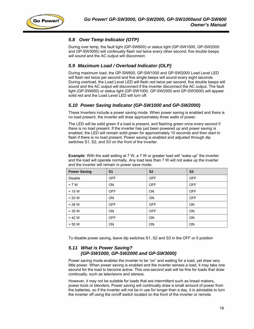
5.10 Power Saving Indicator (GP-SW1000 and GP-SW2000) These Inverters include a power saving mode. When power saving is enabled and there is no load present, the inverter will draw approximately three watts of power.
The LED will be solid green if a load is present, and flashing green once every second if there is no load present. If the inverter has just been powered up and power saving is enabled, the LED will remain solid green for approximately 10 seconds and then start to flash if there is no load present. Power saving is enabled and adjusted through dip switches S1, S2, and S3 on the front of the inverter.
Example: With the watt setting at 7 W, a 7 W or greater load will “wake up” the inverter and the load will operate normally. Any load less than 7 W will not wake up the inverter and the inverter will remain in power save mode.
Power Saving S1 S2 S3
Disable OFF OFF OFF
> 7 W ON OFF OFF
> 15 W OFF ON OFF
> 20 W ON ON OFF
> 28 W OFF OFF ON
> 35 W ON OFF ON
> 42 W OFF ON ON
> 50 W ON ON ON
To disable power saving, leave dip switches S1, S2 and S3 in the OFF or 0 position
5.11 What is Power Saving? (GP-SW1000, GP-SW2000 and GP-SW3000)
Power saving mode enables the inverter to be “on” and waiting for a load, yet draw very little power. When power saving is enabled and the inverter senses a load, it may take one second for the load to become active. This one-second wait will be fine for loads that draw continually, such as televisions and stereos.
However, it may not be suitable for loads that are intermittent such as bread makers, power tools or blenders. Power saving will continually draw a small amount of power from the batteries, so if the inverter will not be in use for longer than a day, it is advisable to turn the inverter off using the on/off switch located on the front of the inverter or remote.
Go Power! GP-SW3000, GP-SW2000, GP-SW1000and GP-SW600Owner’s Manual
20
5.12 Remote The GP-SW1000, GP-SW2000 and GP-SW3000 are available with an optional remote. The remote will turn the inverter on and off and indicate normal operation or any faults that have caused the inverter to shut down. The remote will show battery voltage and power consumption.
The remote will show if the battery voltage is too high and will sound an alarm if the battery voltage falls too low (Under Voltage). The remote will also sound an alarm if the output power is above the inverter specifications (Overload). The Under Voltage and Overload alarm consists of five single beeps every eight seconds.
Go Power! GP-SW3000, GP-SW2000, GP-SW1000and GP-SW600Owner’s Manual
21
6. Operating limits
6.1 Input voltage: The power inverter will operate from input voltage ranging 10.5 to 15 V (12 V) or 21 to 30 V (24 V). If the voltage drops below 11 V (12 V) or 22 V (24 V), the Input Level LED will flash red twice per second and five single beeps will sound every eight seconds. If the voltage drops below 10.5 V (12 V) or 21 V (24 V), the Input Level LED will flash red twice per second, five double beeps will sound, the fault light will come on and the AC output will disconnect. This protects your battery from being over discharged.
The power inverter will also shut down if the input voltage exceeds 15 V (12 V) or 30 V (24 V). This protects the inverter against excessive input voltage. If the voltage rises above 15 V (12 V) or 30 V (24 V), the Input Level LED will flash red four times per second, five double beeps will sound, the fault light will come on, and the AC output will disconnect.
Although the power inverter incorporates protection against over voltage, it may still be damaged if the input voltage is allowed to exceed 20 V (12 V) or 40 V (24 V).
Go Power! GP-SW3000, GP-SW2000, GP-SW1000and GP-SW600Owner’s Manual
22
7. Troubleshooting
7.1 Common problems Television interference: Operation of the power inverter can interfere with television reception on some channels. If this situation occurs, the following steps may help to alleviate the problem:
• Make sure that the chassis ground lug on the back of the power inverter is solidly connected to the ground system of your vehicle, boat or home.
• Do not operate high power loads with the power inverter while watching television.
• Make sure that the antenna feeding your television provides an adequate "snow free) signal and that you are using good quality cable between the antenna and the TV.
• Move the television as far away from the power inverter as possible.
• Keep the cables between the battery and the power inverter as short as possible and twist them together with about two to three twists per foot. This minimizes radiated interference from the cables.
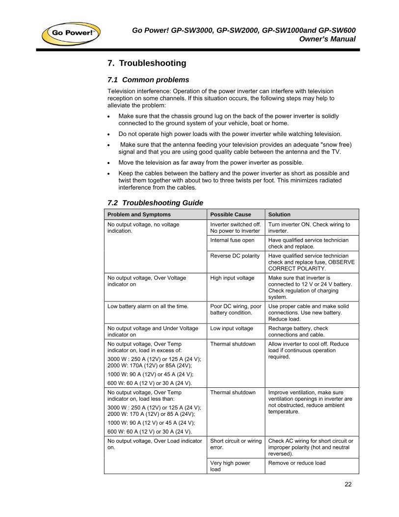
7.2 Troubleshooting Guide Problem and Symptoms Possible Cause Solution
Inverter switched off. No power to inverter
Turn inverter ON. Check wiring to inverter.
Internal fuse open Have qualified service technician check and replace.
No output voltage, no voltage indication.
Reverse DC polarity Have qualified service technician check and replace fuse, OBSERVE CORRECT POLARITY.
No output voltage, Over Voltage indicator on
High input voltage Make sure that inverter is connected to 12 V or 24 V battery. Check regulation of charging system.
Low battery alarm on all the time. Poor DC wiring, poor battery condition.
Use proper cable and make solid connections. Use new battery. Reduce load.
No output voltage and Under Voltage indicator on
Low input voltage Recharge battery, check connections and cable.
No output voltage, Over Temp indicator on, load in excess of: 3000 W : 250 A (12V) or 125 A (24 V); 2000 W: 170A (12V) or 85A (24V); 1000 W: 90 A (12V) or 45 A (24 V); 600 W: 60 A (12 V) or 30 A (24 V).
Thermal shutdown Allow inverter to cool off. Reduce load if continuous operation required.
No output voltage, Over Temp indicator on, load less than: 3000 W : 250 A (12V) or 125 A (24 V); 2000 W: 170 A (12V) or 85 A (24V); 1000 W: 90 A (12 V) or 45 A (24 V); 600 W: 60 A (12 V) or 30 A (24 V).
Thermal shutdown Improve ventilation, make sure ventilation openings in inverter are not obstructed, reduce ambient temperature.
Short circuit or wiring error.
Check AC wiring for short circuit or improper polarity (hot and neutral reversed).
No output voltage, Over Load indicator on.
Very high power load
Remove or reduce load
Go Power! GP-SW3000, GP-SW2000, GP-SW1000and GP-SW600Owner’s Manual
23
8. Maintenance Very little maintenance is required to keep your inverter operating properly. You should clean the exterior of the unit periodically with a damp cloth to prevent accumulation of dust and dirt. At the same time, tighten the screws on the DC input terminals.
Go Power! GP-SW3000, GP-SW2000, GP-SW1000and GP-SW600Owner’s Manual
24
9. Warranty
9.1 Go Power! 2 Year Limited Warranty Go Power! provides the following limited 2 year warranty (“Warranty”) coverage as applicable to the purchaser (“Purchaser”) of the Go Power! branded product (“Product”) directly from Go Power! The following constitutes the terms and conditions of that limited warranty.
9.1.1 What the Go Power! Warranty Covers and for How Long Subject to the exclusions and claim procedure set out below, Go Power! warrants for a period of 2 years from the date of purchase at the point-of-sale to the original end-user customer (“Sale Date”), that the Go Power! Product provides coverage as follows:
For the period ending 2 years from the Sale Date, Go Power! will, at Go Power!’s discretion, repair or replace the Product which fails to meet the Product Specifications due to a defect in materials or workmanship or apply credit towards the purchase of new Go Power! Product.
To exercise this right, the Purchaser shall ship, at its own expense, and return the Product to Go Power! according to the return instructions detailed below, and Go Power! will, repair or replace the Product and return it to the Purchaser free of charge, or offer credit towards the purchase of new Product.
Go Power! shall be entitled, at its discretion, to use new and/or reconditioned parts in performing warranty repair or providing a replacement Product. Go Power! also reserves the right to use parts or Product of original or improved design in any repair or replacement. All replaced Product and/or any parts removed from repaired Products become the property of Go Power!
If Go Power! chooses to repair or replace a Product, the above warranty will continue to apply and remain in effect for the balance of the warranty period calculated from the Sale Date (and not the repair or replacement date).
If Go Power! chooses to offer a credit towards the purchase of new Product, then the warranty in effect and applicable to the new Product shall apply to the new Product.
9.1.2 What the Go Power! Warranty Does Not Cover Go Power!’s Warranty does not provide coverage for the following which are expressly excluded from the above warranty:
• Failure due to normal wear and tear of the Product.
• Failure caused by separate computer software supplied with or associated with a Go Power! Product.
• Failure due to fire, water, neglect, improper installation, generalized corrosion, biological infestations, or input voltages that create operating conditions beyond the maximum or minimum listed in the Go Power! specifications including lightning strikes.
• Products which have been altered other than by Go Power! or authorized by Go Power!
• Products that have their original identification (trademark, serial number) markings defaced altered or removed.
• Products utilized as a component part of a product expressly warranted by another manufacturer.
• Operation or storage of the Product outside the specification ranges, and/or alteration or deployment of Go Power! Products other than in accordance with any published or provided user, storage or maintenance requirements.
Go Power! GP-SW3000, GP-SW2000, GP-SW1000and GP-SW600Owner’s Manual
25
• Failure that is in any way attributable to the improper use, storage, maintenance, installation or placement of the Go Power! Product.
• Failure caused by abuse, misuse, abnormal use, or use in violation of any applicable standard, code or instructions for use in installations, including, but not limited to, those contained in the National Electrical Code, the Standards for Safety of Underwriters Laboratory, Inc., Standards for the International Electrotechnical Commission, Standards for the American National Standards Institute, or the Canadian Standards Association.
• Failure due to acts of God.
9.1.3 Restrictions and Limitations to Go Power!’s Warranty • This Warranty is not transferable and only applies to the Purchaser.
• Go Power! does not warrant the results obtained from the implementation of recommendations made by Go Power! or its authorized distributors concerning the use, design or application of Go Power! Products
• The end-user who purchases the Product assumes all responsibility and liability for loss or damage resulting from the handling or use of Go Power! Products.
• Go Power!'s liability on any claim, whether in warranty, contract, negligence, or any other legal theory, for loss, damage or injury arising directly or indirectly from or in relation to the use of the Go Power! Product shall in no event exceed the purchase price of the Go Power! Product which gave rise to the claim. IN NO EVENT SHALL GO POWER! BE LIABLE FOR PUNITIVE, SPECIAL, INCIDENTAL OR CONSEQUENTIAL DAMAGES WHETHER FORSEEABLE OR NOT INCLUDING BUT NOT LIMITED TO LOSS OF PROFITS OR REVENUES, LOSS OF USE OF GOODS, OR LOSS OF BARGAIN.
• The Warranty set out above is the sole warranty granted by Go Power! with respect to the Product. No oral understanding, representations or warranties shall be of any effect and Go Power! makes no further warranties, express or implied concerning the Go Power! Products other than the Warranty set out above. The Buyer, where permitted by applicable law, hereby expressly waives any statutory or implied warranty that the Go Power! Product shall be merchantable or fit for a particular purpose.
9.2 Warranty Return Procedure This warranty procedure is based on the typical flow of sale: Go Power! → Supplier → Dealer → End User
9.2.1 End Users Contact your sales representative or Dealer and discuss the problem. Often the sales representative can troubleshoot common scenarios. If applicable, warranty will be handled between the End User and the Dealer. Go-Power! will only accept returned items from an End User as a last resort. If you are unable to contact the Dealer, or the Dealer refuses to provide service, please contact Go-Power! directly.
9.2.2 Dealers Dealers will handle warranty either through their supplier or Go-Power! if they qualify as a Purchaser.
9.2.3 Units bought directly from Go Power! The Purchaser will return the product, freight prepaid, to Go Power! You must obtain a Return Material Authorization (RMA) number from Go Power! before returning a product. The RMA number MUST be clearly indicated on the outside of the box.
Items received without an RMA number will be refused.
Go Power! GP-SW3000, GP-SW2000, GP-SW1000and GP-SW600Owner’s Manual
26
9.3 Additional Information Unless approved by Go Power! management, all product shipped collect to Go Power! will be refused.
Test items or items that are not under warranty, or units that are not defective, will be charged a minimum bench charge of ($50.00 US) plus taxes and shipping.
A 15% restocking charge will be applied on goods returned and accepted as “new” stock.
9.4 Out of Warranty Items Go-Power! electronic products are non-repairable, Go-Power! does not perform repairs on its products nor does it contract out those repairs to a third party. Go-Power! does not supply schematics or replacement parts for any of its electronic products.
Go Power! GP-SW3000, GP-SW2000, GP-SW1000and GP-SW600Owner’s Manual
27
10. Configuring your GP-SW3000, GP-SW2000, GP-SW1000, and GP-SW600
10.1 Configuring the Dip Switches GP-SW3000, GP-SW2000, and GP-SW1000
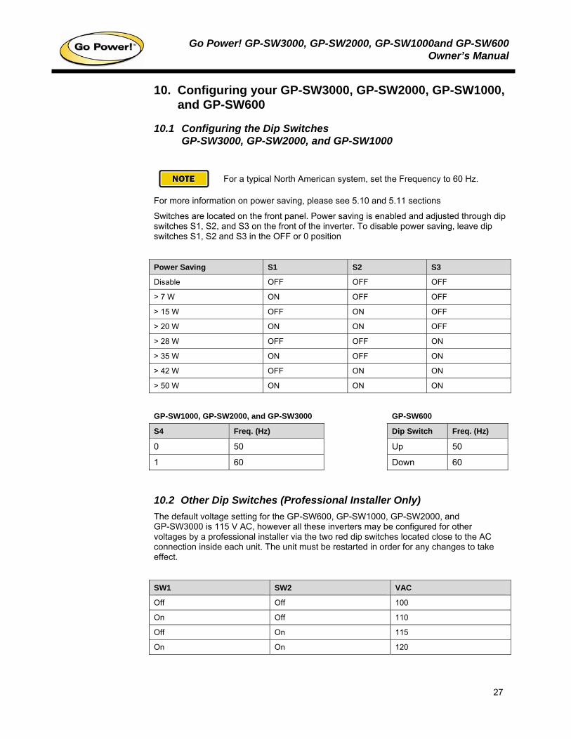
For a typical North American system, set the Frequency to 60 Hz.
For more information on power saving, please see 5.10 and 5.11 sections
Switches are located on the front panel. Power saving is enabled and adjusted through dip switches S1, S2, and S3 on the front of the inverter. To disable power saving, leave dip switches S1, S2 and S3 in the OFF or 0 position
Power Saving S1 S2 S3
Disable OFF OFF OFF
> 7 W ON OFF OFF
> 15 W OFF ON OFF
> 20 W ON ON OFF
> 28 W OFF OFF ON
> 35 W ON OFF ON
> 42 W OFF ON ON
> 50 W ON ON ON
GP-SW1000, GP-SW2000, and GP-SW3000 GP-SW600
S4 Freq. (Hz) Dip Switch Freq. (Hz)
0 50 Up 50
1 60 Down 60
10.2 Other Dip Switches (Professional Installer Only) The default voltage setting for the GP-SW600, GP-SW1000, GP-SW2000, and GP-SW3000 is 115 V AC, however all these inverters may be configured for other voltages by a professional installer via the two red dip switches located close to the AC connection inside each unit. The unit must be restarted in order for any changes to take effect.
SW1 SW2 VAC
Off Off 100
On Off 110
Off On 115
On On 120

© 2008 Carmanah Technologies Corporation www.carmanah.com
Go Power!
Building 4, 203 Harbour Road Victoria, British Columbia
Canada V9A 3S2 Toll Free: 1.877.722.8877 | Fax: +1.250.380.0062
Email: [email protected]
Number: GP-SW600_SW3000_57150_Manual_vB
57150